Embed Size (px)
Citation preview

FA-PC VPC Series
VPC-3000
User’s Manual
CONTEC CO., LTD.

User’s Manual i
Check Your Package
Thank you for purchasing the CONTEC product. The product consists of the items listed below. Check, with the following list, that your package is complete. If you discover damaged or missing items, contact your retailer or the general CONTEC information. We require the registration card to notify you of details such as new product information. Be sure to fill in and return this card.
◆◆◆◆Product Configuration List
VPC-3000 Series
Name Pcs
SETUP-PC 1
Wall Mount Stand 2
AC Cable (125V spec) 1
I/O Terminal Connector 2
Waranty Certificate 1
VPC-3000 Product guide/Precaution List 1
Serial Number Label 1
DVI Connector 1
Name Plate 1
Rubber Foot 4
Recovery Media / Driver Disc 1set *1
Truss head screw M3 x 5 *2
Truss head screw M4 x 6 *2
Flat head screw #6-34 x 4 *2
Flat head screw M3 x 4 *2
Clamp 1set *2
On-site Maintenance Serivce Pack *3
Mouse *3
Keyboard *3 *1 A recovery disk set is included with the OS installed model. A driver disk is included with the model
that does not have an OS. *2 The quantity varies depending on the product configuration. *3 This is included when it is selected as an option.

ii User’s Manual
◆◆◆◆Product Configuration Image
※For details on the presence and quantities of the items that make up this product, see the product configuration list.

User’s Manual iii
Table of Contents ◆Product Configuration List ......................................................................................................... i ◆Product Configuration Image .................................................................................................... ii
Table of Contents ................................................................................................................................iii
1.INTRODUCTION 1
Overview .............................................................................................................................................. 1 ◆Basic performance ..................................................................................................................... 1 ◆Commodity model ..................................................................................................................... 2 ◆Supported OS ............................................................................................................................ 2
Customer support ................................................................................................................................. 3 ◆Web Site .................................................................................................................................... 3 ◆Limited One-Year Warranty...................................................................................................... 3 ◆How to Obtain Service .............................................................................................................. 3 ◆Liability ..................................................................................................................................... 3
Safety precaution.................................................................................................................................. 4 ◆Safety infomation ...................................................................................................................... 4 ◆Handling precautions................................................................................................................. 5
2.ABOUT THE PRODUCT 7
Specification ........................................................................................................................................ 7
Physical dimensions ............................................................................................................................. 9
Mother board Block chart .................................................................................................................. 12
Keyboard specification ....................................................................................................................... 13
Mouse specification ........................................................................................................................... 13
3.HARDWARE SETUP 15
Before Using the VPC-3000 for the First Time .................................................................................. 15
Hardware setup .................................................................................................................................. 16 ◆Removing the top cover and drive bay .................................................................................... 16 ◆Locations and settings of internal connectors and jumpers ...................................................... 19 ◆Jumper setting ......................................................................................................................... 21 ◆Mother board internal connector ............................................................................................. 24 ◆Attaching the hard disk ........................................................................................................... 34 ◆Replacing the optical drive ...................................................................................................... 37 ◆Attaching the extension memory ............................................................................................. 39 ◆Attaching the extension board ................................................................................................. 40 ◆Removing the dustproof filter ................................................................................................. 41 ◆Attaching the wall mount stand ............................................................................................... 42 ◆Removing the wall mount stand .............................................................................................. 42 ◆FG connection ......................................................................................................................... 43

iv User’s Manual
◆Installation requirements ......................................................................................................... 44 ◆Removing the DIO cover......................................................................................................... 46 ◆Option: Attaching and removing the mirror card ..................................................................... 47
4.BIOS SETUP 49
Starting the setup screen ..................................................................................................................... 49
Key operation ..................................................................................................................................... 50
Main window ..................................................................................................................................... 51 ◆Setting of the date and time ..................................................................................................... 52
Setting of the start password............................................................................................................... 53
Release of set the password ................................................................................................................ 54
Changing to the device boot order ...................................................................................................... 55
Selecting to the IDE device ................................................................................................................ 55
Setting for the power on (AT power operation) by the AC power-supply turning on ......................... 56
Factory default setting ........................................................................................................................ 57 ◆MAIN ...................................................................................................................................... 58 ◆Configuration .......................................................................................................................... 59 ◆Boot ......................................................................................................................................... 69 ◆Security ................................................................................................................................... 70 ◆Save & Exit ............................................................................................................................. 70
5.EACH COMPONENT FUNCTION 71
Component name ............................................................................................................................... 71 ◆VPC-3000 front view .............................................................................................................. 71 ◆VPC-3000 rear view ................................................................................................................ 72
Component Function .......................................................................................................................... 73 ◆Keyboard interface .................................................................................................................. 73 ◆Mouse interface ....................................................................................................................... 73 ◆Sirial port interface .................................................................................................................. 74 ◆DVI-I interface ........................................................................................................................ 75 ◆Printer port inteface ................................................................................................................. 76 ◆Reset switch ............................................................................................................................ 77 ◆Power switch ........................................................................................................................... 77 ◆USB port ................................................................................................................................. 77 ◆Ethernet ................................................................................................................................... 78 ◆Digital I/O interface................................................................................................................. 79 ◆Audio interface ........................................................................................................................ 81 ◆Serial ATA interface ............................................................................................................... 82
6.SOFTWARE UTILITY 83
Driver DVD ....................................................................................................................................... 83
Various drivers ................................................................................................................................... 84

User’s Manual v
7.SOFTWARE RAID SETUP 85
Starting the setup screen ..................................................................................................................... 85
Main window ..................................................................................................................................... 86
Create RAID drive (Mirroring) ......................................................................................................... 87
Delete RAID drive (Mirroring) .......................................................................................................... 89
Software RAID monitoring tool (Rapid Storage Technology) ........................................................... 90 ◆Rapid storage Technology Install ............................................................................................ 90 ◆Starting the Rapid storage technology ..................................................................................... 90 ◆Exiting the Rapid storage technology ...................................................................................... 91 ◆Making of mirroring synchronize ............................................................................................ 92 ◆Create RAID drive (Mirroring) ............................................................................................... 93 ◆Delete RAID drive (Mirroring) ............................................................................................... 96 ◆For the error ............................................................................................................................ 97 ◆Confirming the error log.......................................................................................................... 98
RAID setup when replacing the HDD ................................................................................................ 99
8.APPENDIX 101
Battery specifications ....................................................................................................................... 101 ◆Removing the battery when disposing the product ................................................................ 101 ◆Disposing the battray ............................................................................................................. 101

vi User’s Manual

0 1.Introduction
User’s Manual 1
1111....Introduction
Overview This product is a BTO industrial computer that is equipped with a CPU Intel® Core i7 4770S processor (3.10GHz), Core i5 4570S (2.9GHz) processor, or Celeron G1820 processor (2.7GHz). The Intel® Q87 chipset with DDR3 memory (4GB, 8GB, or 16GB) provides advanced computing and graphical performance. This product features a variety of interfaces such as 8 USB ports (front: 2, rear: 6), 2 1000BASE-T ports, 1 RS-232 port, and 1 parallel port. This unit is ideal for a wide range of embedded applications such as control devices and information terminals based on general-purpose PC operating systems. This series provides carefree use under harsh working conditions such as FA, achieving superb environmental resistance and a long-term stable supply due to careful selection of parts such as an embedded CPU and chipset.
◆◆◆◆Basic performance
・ Equipped with an Intel® Core i7 CPU (*Core i7 model) Embedding a high-performance CPU in the VPC-3000 series enables its low price.
・ Uses the Intel® Q87 chipset Employing an embedded-style chipset with the VPC-3000 series enables its long-term stable supply.
・ Supports mirroring (RAID1) Mirroring enables the construction of redundant systems. [Hardware RAID] Selecting the optional mirror card enables the construction of hardware mirroring. Hot-swapping is
also supported. [Software RAID] Software mirroring can be constructed, but hot-swapping is not supported. ・ Uses a chassis suitable for embedded applications
Taking advantage of our rich experience, we have designed the VPC-3000 series with optimization for heat dissipation, dampening for operating vibrations, and consideration for scalability.
・ Supports high-speed, high-capacity memory The VPC-3000 series supports DDR3 SDRAM DIMM modules (4GB, 8GB, or 16GB) designed for high transfer speeds, flexibly addressing memory-consuming applications such as image processing.

0 1.Introduction
2 User’s Manual
◆◆◆◆Commodity model
◆◆◆◆Supported OS
・ Windows 7 Professional for Embedded System (JPN) 32bit
・ Windows 7 Professional for Embededd System (JPN) 64bit
・ Windows 8.1 Industry Pro (JPN) 64bit
・ Windows 7 Ultimate for Embededd System (ENU/JPN/CHS) 32bit

0 1.Introduction
User’s Manual 3
Customer support CONTEC provides the following support services for you to use CONTEC products more efficiently and comfortably.
◆◆◆◆Web Site
Japanese http://www.contec.co.jp/ English http://www.contec.com/ Chinese http://www.contec.com.cn/
■Latest product information
CONTEC provides up-to-date information on products. CONTEC also provides product manuals and various technical documents in the PDF.
■Note! For product information
Contact your retailer if you have any technical question about a CONTEC product or need its price, delivery time, or estimate information.
◆◆◆◆Limited One-Year Warranty
CONTEC products are warranted by CONTEC CO., LTD. to be free from defects in material and workmanship for up to one year from the date of purchase by the original purchaser. Repair will be free of charge only when this device is returned freight prepaid with a copy of the original invoice and a Return Merchandise Authorization to the distributor or the CONTEC group office, from which it was purchased. This warranty is not applicable for scratches or normal wear, but only for the electronic circuitry and original products. The warranty is not applicable if the device has been tampered with or damaged through abuse, mistreatment, neglect, or unreasonable use, or if the original invoice is not included, in which case repairs will be considered beyond the warranty policy.
◆◆◆◆How to Obtain Service
For replacement or repair, return the device freight prepaid, with a copy of the original invoice. Please obtain a Return Merchandise Authorization number (RMA) from the CONTEC group office where you purchased before returning any product. * No product will be accepted by CONTEC group without the RMA number.
◆◆◆◆Liability
The obligation of the warrantor is solely to repair or replace the product. In no event will the warrantor be liable for any incidental or consequential damages due to such defect or consequences that arise from inexperienced usage, misuse, or malfunction of this device.

0 1.Introduction
4 User’s Manual
Safety precaution Understand the following definitions and precautions to use the product safely.
◆◆◆◆Safety infomation
This document provides safety information using the following symbols to prevent accidents resulting in injury or death and the destruction of equipment and resources. Understand the meanings of these labels to operate the equipment safely.
DANGER indicates an imminently hazardous situation which, if not avoided, will result in death or serious injury.
WARNING indicates a potentially hazardous situation which, if not avoided, could result in death or serious injury.
CAUTION indicates a potentially hazardous situation which, if not avoided, may result in minor or moderate injury or in property damage.

0 1.Introduction
User’s Manual 5
◆◆◆◆Handling precautions
CAUTION indicates a potentially hazardous situation which, if not avoided, may result in minor or moderate injury or in property damage.
・ Do not use or store the product in a location exposed to extremely high or low temperature or susceptible to rapid temperature changes. Example ・Exposure to direct sun
・In the vicinity of a heat source ・ Do not use the product in extremely humid or dusty locations. It is extremely dangerous to use the
product with its interior penetrated by water or any other fluid or conductive dust. If the product must be used in such an environment, install it on a dust-proof control panel, for example.
・ Avoid using or storing the device in locations subject to shock or vibration. ・ Do not use the product in the vicinity of devices that generate strong magnetic force or noise.
Such devices will cause this device to malfunction. ・ Do not use or store the product in the presence of chemicals. ・ To clean, wipe it gently with a soft cloth dampened with either water or mild detergent.
Do not use chemicals or a volatile solvent, such as benzene or thinner, to prevent pealing, discoloration of the paint, or deterioration of resin.
・ As continuous operation of the equipment may shorten the life of the hard disk drive, use it in stand-by mode.
・ Be sure to unplug the power cable from a wall outlet before plugging or unplugging a extension board or any connector.
・ CONTEC reserves the right to refuse to service a product modified by the user. ・ In the event of failure or abnormality (foul smells or excessive heat generation), unplug the power
cord immediately and contact your retailer. ・ Use an AC cable suitable for your supply voltage and outlet/plug. (The supplied cable is for 125V
AC. ・ The hard disk must be replaced when the power of the main unit is off. It is not hot-swappable.
Removing the hard disk during operation may damage the system. (However, hardware raid is excluded.)
・ Component Life: (1)Power・・・・・・・・・During continuous operation at 40℃, the assumed life is about four years
(vertical installation). However, it may be shortened due to operating temperature (high temperatures).
(2)Battery・・・・・・・・The internal calendar clock and CMOS RAM are backed by a Lithium primary battery. The backup time at a temperature of 25°C with the power disconnected is 10 years or more.
(3)Chassis FAN・・・During operation at 40℃, the assumed life is about six years. However, it may be shortened due to operating temperature.
* Replacement of expendables is handled as a repair (there will be a charge).
・ To connect with peripherals, use a grounded, shielded cable.
・ Do not use a UPS (uninterruptible power supply) with square-wave output, as connecting it may damage the system.
・ Risk of explosion if battery is replaced by an incorrect type. Dispose of used batteries according to the instructions.
・ Abandon a used battery appropriately according to the instruction of the municipality.

0 1.Introduction
6 User’s Manual
FCC PART 15 Class A Notice
This equipment has been tested and found to comply with the limits for a Class A digital device,pursuant to part 15 of the FCC Rules. These limits are designed to provide reasonable protection
against harmful interference when the equipment is operated in commercial environment.
This equipment generates, uses, and can radiate radio frequency energy and, if not installed and
used in accordance with the instruction manual, may cause harmful interference to radio
communications. Operation of this equipment in a residential area is likely to cause harmful
interference at his own expense.
NNNNOOOOTTTTEEEE
Change or modifications not expressly approved the manufacturer can void the user's authority tooperate this equipment.
WWWWAAAARRRRNNNNIIIINNNNGGGG TTTTOOOO UUUUSSSSEEEERRRR
The object of the standard of this product becomes only a main body.
Copyright
・ No part of this document may be copied or reproduced in any form by any means without prior written consent of CONTEC CO., LTD.
・ CONTEC CO., LTD. makes no commitment to update or keep current the information contained in this document. The information in this document is subject to change without notice.
・ All relevant issues have been considered in the preparation of this document. Should you notice an omission or any questionable item in this document, please feel free to notify CONTEC CO., LTD.
・ Regardless of the foregoing statement, CONTEC assumes no responsibility for any errors that may appear in this document or for results obtained by the user as a result of using this product.
・ Intel, Core, Pentium are registered trademarks of Intel Corporation. MS, Microsoft and Windows are trademarks of Microsoft Corporation. Other brand and product names are trademarks of their respective holder. ™ and ® mark are omitted in this document.
The latest version manual downloads from CONTEC web site.

User’s Manual 7
2....About the product
Specification Functional specification System Specification
CPU※1 ・Intel Celeron G1820 --------------------------- 2.7GHz ・Intel Core i5 4570S --------------------------- 2.9GHz ・Intel Core i7 4770S -------------------------- 3.10GHz
Chipset Intel Q87 BIOS AMI BIOS
Memory※1 4096MB(4096MB×1), 8192MB(4096MB×2), 16384MB(4096MB×4)(DDR3 SDRAM DIMM)
Hard disk drive※1 ・SATAⅡ 3.5”HDD 250GB/2TB
(Software/Hardware)RAID1 ・SATAⅡ 3.5”HDD 250GB/2TB ×1 or ×2
Optical drive
DVD super multi drive Max. reading speed DVD-ROM x16, CD-ROM x48, DVD+/-R x24, Max. writing speed DVD+/-R x24, DVD+RW x8, DVD-RW x6,
DVD+/-R-DL x12, DVD-RAM x12, CD-R x48, CD-RW x32
Display Digital, Analog combined use DVI-I 29pin, DisplayPort 20pin USB port USB2.0 front 2port, Rear 2port, USB3.0 rear 4port PS/2 port 2port (Keyboard/Mouse combo type)
Audio Realtek ALC892 High Definition (Mic-in, Line-in, Line-out)
Serial COM1,2,3,4 (RS-232) ※2 D-SUB 9pin×4 Parallel D-SUB 25pin×1 LAN port 100BASE-TX/1000BASE-T RJ45×2
LAN controller Intel I218-LM GbE Ethernet Controller(LAN1) Intel I210-AT GbE Ethernet Controller (LAN2)
Digital I/O Front:LED output x2 Rear:output x2, Input x4 (Software API support, User application available)
RAS function WDT:1sec~255sec (Ressting operatio by time up) Remote reset / Remote power on External input signal Software RAS function (FAN rotation, temperature, Voltage data reading)
Extended slot PCI Express x16 (Max:176mm(L)×110mm(H)) : 1 slot PCI Express x4 (Max:176mm(L)×110mm(H)) : 1 slot PCI (Max:176mm(L)×110mm(H)) : 2 slot
OS※1
・Windows 7 Professional (32bit) JPN ・Windows 7 Professional (64bit) JPN ・Windows 7 Ultimate (32bit) [ENU/JPN/CHS] ・Windows 8.1 Industry (64bit) JPN
Stand Wall mount Physical dimensions(mm) /Weight 370(W) x 470(D) x 166(H) (No protrusions) / About 14Kg※3
Power 400W ATX Power (100-240VAC(50-60Hz) Automatic input switch) ※1 Implement and install the options you selected. ※2 The connector of the D-SUB 9 pin is output from the back of the chassis. ※3 Only the weight of the main unit. Appended goods and the packing box are excluded.

8 User’s Manual
Ambient specification
Operating temperature/humidity 5~40℃/20~80%RH(No condensation) Storage temperature/humidity -20℃~60℃/5~80%RH(No condensation) Floating dust particles/Corrosive gases Not to be excessive/None
Line-noise resistance
Static electricity resistance
Contact discharge / ± 4 K V ( E N 6 1 0 0 0 - 4 - 2 L e v e l 2 , I E C 1 0 0 0 - 4 - 2 L e v e l 2
Atmospheric discharge / ± 8 K V ( E N 6 1 0 0 0 - 4 - 2 L e v e l 3 , I E C 1 0 0 0 - 4 - 2 L e v e l 3
Line noise AC line/2KV,Signal line/1KV (EN61000-4-4Level3,IEC1000-4-4Level3)
Vibration resistance Sweep resistance
10~57Hz/semi-amplitude 0.015m 57~150Hz/0.2G 40 min each X,Y, and Z directions (JIS C0040 compliant、IEC68-2-6 compliant)
Impact resistance 10G, half-sine shock for 11 ms in X,Y, and Z directions (JIS C0041 compliant, IEC68-2-27 compliant)
Standard RoHS FCC part 15 class A
Note) Do not use under environmental conditions beyond normal specifications. The system may malfunction.
Option Mirror card specification
Item Specification Number of connected drives 2 RAID level 1 Storage capacity Max. 2TB Cache memory size 1MB Host interface S-ATA Max. data transfer rate:3Gbps Drive interface S-ATA Max. data transfer rate:3Gbps Range of power-supply voltage 4.75VDC~5.25VDC
Current consumption 1.1A ~ 1.5A Physical dimensions (L×W) 96mm × 98.2mm Weight 49g (max.)

User’s Manual 9
Physical dimensions VPC-3000
Figure 2.1 VPC-3000

10 User’s Manual
At installation the wall mount stand of VPC-3000 (horizontal installation)
Figure 2.2 At installation the wall mount stand of VPC-3000 (horizontal installation)

User’s Manual 11
At installation the wall mount stand of VPC-2000 (Vertical installation)
Figure 2.3 At installation the wall mount stand of VPC-3000 (Vertical installation)

12 User’s Manual
Mother board Block chart
Figure 2.4 Motherboard Block chart

User’s Manual 13
Keyboard specification Item Specification
Key array Japanese 109 key, English 104 key Key switch Membrane switch Length of cable(mm) 1500mm ~ 1700mm
It becomes optional of VPC-3000 in the keyboard.
Please inquire details like the specification etc. of the keyboard separately.
Moreover, the above-mentioned keyboard becomes a standard off the subject.
Mouse specification Item Specification
Electrical specification
Operation voltage DC +5V (±0.5V)
Physical specification
Interface (Connector) PS/2 (mini-DIN6pin male) Body color White Button 3 piece
(One piece on the inside wheel) Number of wheels 1 piece Length of cable 1830mm ~ 1850mm Physical dimensions (H x D x W) 39.5mm x 117mm x 62.1mm
Tracking Resolution 460dpi Environment specification Dustproof/Waterproof/Dripproof Non-correspondence
It becomes optional of VPC-3000 in the mouse.
Please inquire details like the specification etc. of the mouse separately.
Moreover, the above-mentioned mouse becomes a standard off the subject.

14 User’s Manual
User’s Manual 15
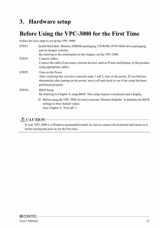
3....Hardware setup
Before Using the VPC-3000 for the First Time Follow the next steps to set up the VPC-3000.
STEP1 Install Hard disk, Memory (DIMM) packaging, CD-ROM, DVD Multi drive packaging, and set Jumper switches.
By referring to the information in this chapter, set the VPC-3000. STEP2 Connect cables.
Connect the cable of necessary external devices, such as Printer and display, to this product using appropriate cables.
STEP3 Tuen on the Power After venifying that you have correctly steps 1 and 2, turn on the power. If you find any abnormality after turning on the power, turn it off and check to see if the setup has been performed properly.
STEP4 BIOS Setup By referring to Chapter 4, setup BIOS. This setup requires a keyboard and a display.
※ Before using the VPC-3000, be sure to execute “Restore Defaults” to initialize the BIOS settings to their default values.
(See Chapter 4, “Exit tab”.)
If your VPC-3000 is a Windows preinstalled model, be sure to connect the keyboard and mouse to it
before turning the poer on for the first time.

16 User’s Manual
Hardware setup ・ Before you start, be sure that the power is turned off.
・ For internal hard disk models, ensure that physical jolts are avoided.
・ Remove only those screws that are explained. Do not move any other screw.
◆◆◆◆Removing the top cover and drive bay
(1) Remove the top cover.
Figure 3.1 Removing the top cover
Slide the case cover horizontally as far as it will go, and then pull it up vertically.
The three knurled screws

User’s Manual 17
(2) Open the front cover.
Figure 3.2 Opening the front cover
When you install/remove a front bezel, take sufficient care to avoid contact with the front LED.
Contact may damage the front LED.
Push on the latch and remove the front cover horizonally.

18 User’s Manual
(3) After remove four screws, the bracket for the extension board.
Figure3.3 Removing the extension board bracket
The four screws

User’s Manual 19
◆◆◆◆Locations and settings of internal connectors and jumpers
Once you have removed the case cover, the bracket for the extension board, and the drive bay unit, you will be able to see the connectors and jumpers as illustrated below.
Figure 3.4 Locations and setting of jumpers and connectors inside the top cover

20 User’s Manual
Table 3.1 Jumper setting
Name Function Factory Setting Reference Page Remarks
JP1 CMOS clear setting 1-2 Short P21 State usually
JP2 ATX/AT setting Open P22 State usually
JP3 COM2 RI setting 2-4 Short P22 State usually
JP4 COM1 RI setting 2-4 Short P23 State usually
Table 3.2 Connector setting
Name Function Reference Page
Name Function Reference Page
J1 Display port - J21 Internal USB2.0 connector -
J2 DVI-I connector - J22 DDR3 socket -
J3 USB2.0 connector - J23 DDR3 socket -
J4 Audio jack - J24 COM6 connector *1 -
J5 PS/2 connector - J25 COM5 connector *1 -
J6 Audio connector - J26 SATA1 -
J7 RJ45 + USB3.0 connector - J27 SATA4 -
J8 RJ45 + USB3.0 connector - J28 COM4 connector *1 -
J9 Battery connector - J29 COM3 connector *1 -
J10 ATX 12V power connector - J30 Digital I/O connector*1 -
J11 Frint panel connector - J31 SATA2 -
J12 PCIe x 8 slot - J32 SATA0 -
J13 ATX24pin power connector - J33 System fan connector -
J14 PCIe x 16 slot - J34 Case open connector -
J15 SMBUS connector - J35 80 port -
J16 Internal USB2.0 connector - J36 COM1 connector *1 -
J17 CPU fan connector - J37 COM2 connector *1 -
J18 DDR3 socket - J38 Parallel port connector *1 -
J19 DDR3 socket - J39 SATA3 -
J20 Internal USB2.0 connector -
*1 This connector is output through wires connected to the chassis. For details, see pages 71 and 72.

User’s Manual 21
◆◆◆◆Jumper setting
■CMOS clear setting : JP1 CMOS Clear will reset the contents of the CMOS to initial BIOS values. Clearing the CMOS will not reset the clock.
Table 3.3 CMOS clear setting
JP1 Function
State usually
(Factory default setting)
CMOS clear
(2-3 short)
Always set CMOS Clear with the AC cable unplugged, and before reconnecting the power, restore it to
its normal setting.
Clearing the CMOS while the power is connected may damage the board.
■ATX/AT mode setting : JP2 Use the factory default settings.
Table 3.4 ATX/AT mode setting
JP2 Function
ATX設定
(Factory default setting)
AT設定
(1-2 ショート)

22 User’s Manual
■COM2 RI function setting : JP3 This enables the setting of the RI function of the COM2 port. RI is set in the factory settings.
Table 3.5 COM2 RI setting : JP3
JP3 Function
+5V
(1-3 short)
RI Signal
(Factory default setting)
+12V
(3-5 shrot)

User’s Manual 23
■COM1 RI function setting : JP4 This enables the setting of the RI function of the COM1 port. RI is set in the factory settings.
Table 3.6 COM1 RI setting : JP4
JP4 Function
+5V
(1-3 short)
RI Signal
(Factory default setting)
+12V
(3-5 shrot)

24 User’s Manual
◆◆◆◆Mother board internal connector
■ATX power-supply connector : J10/J13 Connect the ATX power connector, observing the correct orientation.
Figure 3.5 ATX power supply connector
Table 3.7 J13
Pin Signal Pin Signal 1 +3V 13 +3V
2 +3V 14 -12V
3 GND 15 GND
4 +5V 16 PS_ON
5 GND 17 GND
6 +5V 18 GND
7 GND 19 GND
8 PW_OK 20 -5
9 5V_SB 21 +5V
10 +12V 22 +5V
11 +12V 23 +5V
12 +3V 24 GND
Table 3.8 J10
Pin Signal
1 GND
2 GND
3 +12V
4 +12V
Both J10 and J13 are absolutely necessary power supplies for operation.
Turning on the power for only one of these may damage the system.
J13: ATX 24 pin connector
J10: ATX 12V power-supply connector
4 3
2 1
24 12
13 1

User’s Manual 25
■Fan power supply connector : J17/J33 Connectors for connecting a cooling fan.
A fan with a speed sensor can be used.
Figure 3.6 Fan power supply connector
Table 3.9 J17
Pin Signal
1 GND
2 +12V
3 SENEOR
4 CONTROL
Table 3.10 J33
Pin Signal
1 GND
2 +12V
3 SENEOR
3 1
1
4 J17
J33

26 User’s Manual
■Digital I/O connector : J30 This connects to the digital I/O connector at the rear of the main unit.
For details, refer to Chapter 5 ”Functions of Each Unit” - “Digital I/O Interface”.
Figure 3.7 Digital I/O connector
Table 3.11 J30
Pin Signal Pin Signal
1 +5V 9 GPIO
2 +12V 10 GPIO
3 GPIO 11 GND
4 GPIO 12 GND
5 GPIO 13 RSTBTN
6 GPIO 14 GND
7 GPIO 15 PWRBTN
8 GPIO 16 NC
16
15
2
1

User’s Manual 27
■Internal USB connector : J16,J20,J21 Connectors for connecting the USB connector on the front panel of the case with an USB extension bracket. For the VPC-3000 series, J21 is already connected to the USB connector on the front panel by a special cable.
Both J16 and J20 connectors connect nothing in factory setting.
Figure 3.8 internal USB connector
Table 3.12 J16,J20,J21
Pin Signal Pin Signal
1 +5V 6 USB +
2 +5V 7 Ground
3 USB - 8 Ground
4 USB - 9 Key (No Pin)
5 USB + 10 N/C
1 2
9 10
1 2
9 10
J16
J20
1 2
9 10 J21

28 User’s Manual
■Front panel connector : J11 A connector for connecting the power switch, reset switch, power LED, HDD LED, etc. at the front of the case.
For the VPC-3000 series, they are already connected on the front panel by a special cable.
Figure 3.9 internal front panel connector
Table 3.13 J11
Pin Signal Pin Signal
1 PWR_LED(+) 9 LAN2_LINK
2 Speaker(+) 10 Power On(-)
3 PWR_LED(-) 11 LAN2_ACT
4 N/C 12 Power On(+)
5 LAN1_ACT 13 HDD_LED(+)
6 N/C 14 Reset(+)
7 LAN1_LINK 15 HDD_LED(-)
8 Speaker(-) 16 Reset(-)
RESET SW HDD LED
POWER SW
POWER LED
16 15
2 1

User’s Manual 29
■COM port connector : J24/J25/J28/J29/J36/J37 These are connected to the COM1, COM2, COM3 and COM4 connectors at the rear of the main unit.
Figure 3.10 COM port connector
Table 3.14 J24,J25,J28,J29,J36,J37
RS-232C Pin Signal Pin Signal
1 DCD 6 CTS
2 DSR 7 DTR
3 RXD 8 RI
4 RTS 9 Ground
5 TXD 10 NC
J24/COM6
J28/COM4
J36/COM1
J25/COM5
J29/COM3
J37/COM2 10
9
2
1
10
9
2
1
10
9
2
1
10
9
2
1 10
9
2
1
10
9
2
1

30 User’s Manual
■Audio connector : J6 This connector connects the front-face audio connector and the audio extension bracket.
Neither of these is connected on the VPC-3000 series.
Figure 3.11 Audio connector
Table 3.15 J6
Pin Signal Pin Signal
1 MIC2-L 6 MIC2 Sense resistor
2 GNDAU 7 SENSE-B
3 Mic2-R_Conn 8 NC
4 Pull-high resistor 9 Line2-L_Conn
5 Line2-R_Conn 10 Line2 Sense resistor
J6 10 9
2 1

User’s Manual 31
■System management bus connector : J15 This is a general-purpose communication bus connector between the devices used to manage the system and the power supply. It is not connected on the VPC-3000 series.
Figure 3.12 System management bus connector
Table 3.16 J15
Pin Function
1 SMB_CLK
2 N/C
3 Ground
4 SMB_DAT
5 +5V
J15
5
1

32 User’s Manual
■Parallel port connector : J38 This is connected to the printer port connector on the rear of the VPC-3000.
Figure 3.12 Parallel port connector
Table 3.17 J38
Pin Signal Pin Signal
1 Strobe# 14 Auto Form Feed#
2 Data0 15 Error#
3 Data1 16 Initialization#
4 Data2 17 Printer Select IN#
5 Data3 18 Ground
6 Data4 19 Ground
7 Data5 20 Ground
8 Data6 21 Ground
9 Data7 22 Ground
10 Acknowledge# 23 Ground
11 Busy 24 Ground
12 Paper Empty 25 Ground
13 Printer Select 26 NC
J38 26
25
2
1

User’s Manual 33
■Case open connector : J34 J34 connect nothing in factry setting.
Figure 3.13 Case open connector
Table 3.18 J34
Pin Signal
1 Ground
2 Signal
J34
2 1

34 User’s Manual
◆◆◆◆Attaching the hard disk
(1) Remove the removable case from the drive bay.
Figure 3.11 Extension and replacement of the hard disk (1)
Push the lock and the knob pulls forward.
Lock

User’s Manual 35
(2) Remove and replace the HDD in the removed 5-inch bay.
Figure 3.12 Attaching the hard disk in the drive bay (2)
The four screws
Tighten four screw from a base to fix the hard disk.

36 User’s Manual
(3) Reverse the removal procedure and re-insert it.
The replacement HDD must be an S-ATA drive. Note the specification.
Figure 3.13 Extension and replacement of hard disk (3)
Push it in firmly until it connects to the connector at the back.
※ If the Removable is upper and lower opposite, it cannot be connected.

User’s Manual 37
◆◆◆◆Replacing the optical drive
(1) Remove all cables of the optical drive.
Figure 3.14 Removing all cables of the optical drive (1)
Remove all cables.

38 User’s Manual
(2) Remove two screws from the bracket of the optical drive. It moves to horizontal direction, and it detaches it to the vertical direction.
Figure 3.15 Removing the bracket for the optical drive
(3) Remove four screws and remove the optical drive.
Figure 3.16 Removing the optical drive (4) Reverse the removal procedure and re-insert it.
The two screw
It moves to horizontal direction, and it detaches it to the vertical direction. 。
The four screws
Remove four screws of the bracket side.

User’s Manual 39
◆◆◆◆Attaching the extension memory
(1) Insert expansion memory into the memory slot. For DIMM A and DIMM B, use memory compliant with the specification.
Figure 3.17 Attaching the extension memory
(2) Lock the momory into the slot.
Figure 3.18 Lock the extension memory
J22
J23
J18
J19

40 User’s Manual
◆◆◆◆Attaching the extension board
(1) After unscrew the screw, remove the slot cover in the back of the chassis.
Figure 3.19 Removing the slot cover
(2) The extension board is installed, and it fixes with the screw.
Figure 3.20 Attaching the extension board
Please install it very carefully might interface with the bend of various cables in the case when you install it according to the size of the extension board that installs it.
■Maximum dimensions of boards that can be installed
176mm(L)×110mm(H) (All PCI Express x16,PCI Express x4,PCI bus)
(3) Reverse the attachment procedure and remove it.
Push in the extension board securely as far as it will go.
Screws

User’s Manual 41
◆◆◆◆Removing the dustproof filter
(1) Loosen the knurled screws, and then open the front fan cover.
Figure 3.22 Removing the dustproof filter (1)
(2) Reverse the removal procedure and re-insert it.
Grasp the handle of the fan filter, and then pull it out.

42 User’s Manual
◆◆◆◆Attaching the wall mount stand
(1) Secure the wall mount stand with the four supplied screws.
Figure 3.28 Attaching the wall mount stand
After attaching the stand, the wall mount stands are secured to the chassis.
During attaching the wall mount stands, ensure that the upper and lower it.
◆◆◆◆Removing the wall mount stand
(1) Remove the four screws anchoring the wall mount stands.
(2) Remove the wall mount stands from the chassis.
【Vertical installation】 【Horizontal installation】

User’s Manual 43
◆◆◆◆FG connection
(1) Use a screw to fix the FG cable in place in the position shown in the following figure.
Fix by screw
FG cable

44 User’s Manual
◆◆◆◆Installation requirements
In order to enjoy reliable use of the VPC-3000 series, maintain the following conditions.
■Installable directions
Please do not use by the following installations, and do not set it up in other directions.
Figure 3.29 Installable direction

User’s Manual 45
■Space between the main unit and its surroundings
The main unit of the VPC-3000 series is equipped with air vents and fans for regulating temperature. In order to ensure space for air vents and cables, keep distance described in the following between the front/rear and surrounding equipment, walls, etc.
Note that in the installation location, air must be able to circulate. Please adjust the flow of air so as not to exceed the specification temperature of the product.
Moreover, the unit cannot be used in an enclosed space.
Figure 3.30 Installation condition

46 User’s Manual
◆◆◆◆Removing the DIO cover
This cover is used for protecting the DIO pins.
(1) Removing the DIO cover screws
Remove the two screws anchoring the chassis to the DIO cover and remove the DIO cover.
Fui
Figure 3.31 Removing the DIO cover
(2) Attaching the DIO pin cover
Reverse the procedure of removing the DIO pin cover and attach it.
The two screws

User’s Manual 47
◆◆◆◆Option: Attaching and removing the mirror card
(1) Remove all cables and such connected to the mirror card.
Figure 3.32 Removing all cables
※Starting from the left, the Serial-ATA cables from the upper HDD, lower HDD, mother board, and power supply.
※During connection, ensure that the Serial-ATA cables of the upper and lower HDDs are not reversed.

48 User’s Manual
(2) Loosen the knurled screws, and then open the front fan cover.
Figure 3.33 Opening the front fan cover
(3) Remove the screws that are holding the mirror card in place, and then remove the mirror card.
Figure 3.34 Removing the mirror card
(4) Assembly is the reverse of removal.
※During attaching, ensure that the direction and the upper and lower the mirror card.
The four screws
The two knurled screws

User’s Manual 49
4....BIOS setup
BIOS setup sets various setting during startup. When using the system for the first time, besure to run BIOS setup. Once set up, the specified details will be backed up.
Do not change items not described in this document.
The system may become unstable and may not start up.
Starting the setup screen When you turn on the power to the system, if the system is functioning normally, the “Press DEL to enter SETUP” screen appears. Then press the <DEL> key. After a few seconds, a setup utility can be started.
Figure 4.1 Initial screen
Version 2.15.1236. Copyright (C) 2012 American Megatrends, INC.
SMB-MQ871-LLVA BIOS Ver. 1.10
Press <CTRL + P> to Enter MEBX setup menu
Press <DEL> or <ESC> to enter setup.

50 User’s Manual
Key operation This section provides a list of major key-bound functions during setup.
Table 4.1 Key operation list
Key Function
Up Arrow Move to the previous item
Down Arrow Move to the next item
Left Arrow Move to the item on the left (menu bar)
Right Arrow Move to the item on the right (menu bar)
ESC Main Menu : Quit without saving changes
Sub Menu : Exit Current page to the next higher level menu
Move Enter Move to the item you desired
PgUp key Increase the numeric value or make changes
PgDn key Decrease the numeric value or make changes
+ key Increase the numeric value or make changes
- key Decrease the numeric value or make changes
ESC key Main Menu : Quit and not save changes into CMOS Status Page Setup Menu and Option Page Setup Menu : Exit current page and return to Main Menu
F1 key General help on Setup navigation keys
F4 key Save all the CMOS changes and exit

User’s Manual 51
Main window When you start the setup utility, the main window appears.
Figure 4.2 Example of main window screen
1. The cursor keys <↑>, <↓>, <→>, <←> allow you to navigate through menu items and the <Enter> key allows you to choose among them.
2. After pressing the <F4> key, you can save the current settings by pressing the <Enter> key or the <Y> key.
Main Configuration Boot Security Exit
Project Name
BIOS Verion & Build Date
Processor Information Name
Brand String
Total Memory
Memory Frequency
PCH Information
Name PCH SKU
ME Firmware Mode
ME FW Version
ME Firmware SKU
System Date System Time
Access Level
SMB-MQ871-LLVA
BIOS Ver. 1.10 (04/15/2015 15:20:19)
Haswell
Intel(R) Core(TM) i7-4770S CPU @ 3.10GHz
4096 MB (DDR3)
1333Mhz
LynxPoint Q87
Normal Mode
9.0.30.1482
5MB
[Thu 04/16/2015]
[08:49:14]
Administrator

52 User’s Manual
◆◆◆◆Setting of the date and time
In order to set the date and time of the calendar clock on the VPC-3000 series, follow the following steps.
1. Select “System Time” or “System Date” item from “Main” tab.
2. Select time (Time:) or date (Date:) items by pressing the <Page Up> and <Page Down> keys. You can navigate through items by pressing the cursor keys <←>, <→>.
3. Save setup changes with “Save Changes and Reset” (pressing the <F4> key) and exit.

User’s Manual 53
Setting of the start password After setting a startup password, you must enter the password when you run the setup utility and boot the system.
The password can protect system information and files, limiting their use by other users.
Once you register a password, you will not able to clear password features without the password.
Pay careful enough attention in handling your password.
Password Description
If only the Administrator’s password is set,
then this only limits access to Setup and is only asked for when entering Setup.
If only the User’s password is set, then this is a power on password and must be entered to
boot or enter Setup. In Setup the User will
have Administrator rights. The password length must be
in the following range: Minimum length 3
Maximum length 20
Administrator Password User Password
HDD Security Configuration:
P0: WDC WD2503AB
Set Administrator Password

54 User’s Manual
Password setting The operation of the setup utility Administrator You can change all settings. User You can refer all settings, but you can not change setting of items.
■Administrator Password
1. Select "Administrator Password" from the "Security" tab.
2. "Create New Password" is displayed, so type a password between 3 and 20 characters in length, and then press the <Enter> key.
3. "Confirm New Password" is displayed, so type the same password that you did in step 2., and then press the <Enter> key.
■User Password
1. Select "User Password" from the "Security" tab.
2. "Create New Password" is displayed, so type a password between 3 and 20 characters in length, and then press the <Enter> key.
3. "Confirm New Password" is displayed, so type the same password that you did in step 2., and then press the <Enter> key.
※You cannot set a User Password if an Administrator Password has not been set.
Release of set the password Although the method for doing this is the same as setting a password, when you enter the password, press the <Enter> key without entering anything, and the password will be removed.
Removing the Administrator Password and the user password works the same way.

User’s Manual 55
Changing to the device boot order It is possible to change device boot order.
Boot Option #1
Boot Option #2
[CD/DVD: HL-DT-ST DVDRA ATAPI]
[Hard Disk: WDC WD2503ABYZ (251.0GB)]
1. Select “FIXED BOOT ORDER Priorities” menu from “Boot” tab. 2. Change the settings for “Boot Option #1”, “Boot Otpion #2”, and etc. 3. In order to assign top priority to booting from the CD-ROM, move the cursor to the “Boot Option #1”
item and change the setting to “CD/DVD:…”. (Confirm your choice and setting by pressing the <Enter> key.)
4. After setting the desired order, press the <Esc> key and return to the Main window. Then select the “Exit” tab by cursor and press the <Enter> key. 5. Save setup changes with “Save Changes and reset” and exit.
Selecting to the IDE device Main Configuration Boot Security Exit
SATA Configuration
SATA Controller(s)
SATA Mode Selection SATA Controller Speed
Serial ATA Port 0
Port 0
Hot Plug External SATA
SATA Device Type
[Enabled]
[AHCI] [Default]
WDC WD2503ABYZ (251.0GB)
[Enabled]
[Disabled] [Disabled]
[Hard Disk Drive]
1. Select “SATA Configuration” menu from “Configuration” tab. 2. Select “SATA Mode Selection” item from “SATA Configuration” window. 3. Change the setting for “SATA Mode Selection”. (Options are “IDE”, “RAID”, “AHCI”) 4. After setting the desired order, press the <Esc> key and move to “Exit” tab. 5. Save setup changes with “Save Changes and Reset” and exit.

56 User’s Manual
Setting for the power on (AT power operation) by
the AC power-supply turning on Power Control Configuration
Enable Hibernation ACPI Sleep State
Power Failure
Wake system with Fixed Time
Wkae up Day of Month Wake up hour
Wake up minute Wake up second
Wake on Ring
[Enabled] [S3 only(Suspend to ...]
[Always off]
[Disabled]
0 0
0 0
[Disabled]
1. Select “Powe Control Configuration” menu from “Configuration” tab.
2. Select “Power Failure” item from “Power Control Configuration” window.
3. Change from “Always off” to “Always on”.
4. After setting the above-mentioned 3, press the <Esc> key and move to “Exit”.
5. Save setup changes with “Save Changes and Reset” and exit.

User’s Manual 57
Factory default setting This section describes the CMOS Setup Utility’s factory default settings example of core i7 installation.
By selecting “Load Optimal Defaults” in the Exit tab of the CMOS Setup Utility, you can restore our
factory settings. For operational instructions, follow the following steps.
1. Select “Restore Defaults” menu from “Exit” tab.
2. You are prompted to confirm that you are restoring to initial conditions. Press the <Y> and <Enter> keys.
3. Save setup changes with “Save Changes and Reset” and exit.
The following section describes parameters for the factory default settings of each setting in the CMOS
Setup Utility.
Do not change settings other than the CMOS Setup Utility settings specifically described in this
document. The OS may not function normally otherwise.
We assume no responsibility for trouble caused by changing settings other than the CMOS Setup Utility settings specified.

58 User’s Manual
◆◆◆◆MAIN
Project Name
BIOS Verion & Build Date
Processor Information
Name Brand String
Total Memory
Memory Frequency
PCH Information
Name PCH SKU
ME Firmware Mode ME FW Version
ME Firmware SKU
System Date
System Time
Access Level
SMB-MQ871-LLVA
BIOS Ver. 1.10 (04/15/2015 15:20:19)
Haswell Intel(R) Core(TM) i7-4770S CPU @ 3.10GHz
4096 MB (DDR3)
1333Mhz
LynxPoint Q87
Normal Mode 9.0.30.1482
5MB
[Thu 04/16/2015]
[08:49:14]
Administrator
※As the Main tab differ according to date and PC configuration, the above figure is a sample.

User’s Manual 59
◆◆◆◆Configuration
� CPU Configuration
� Chipset Configuration
� LAN Configuration
� Graphics Configuration
� PCI/PCIE Configuration
� SATA Configuration
� USB Configuration
� Power Control Configuration
� Super IO Configuration
� H/W Monitor
� Serial Port Console Redirection
■CPU Configuration
CPU Configuration Intel(R) Core(TM) i7-4770S CPU @ 3.10GHz CPU Signature Max CPU Speed Min CPU Speed Processor Cores Intel HT Technology Intel VT-x Technology Intel SMX Technology 64-bit EIST Technology CPU C3 state CPU C6 state CPU C7 state Hyper-threading ※1 Active processor Cores Intel Virtualization Technology EIST Turbo Mode ※2 CPU C states
306c3 3100 MHz 800 MHz 4 Supported ※3 Supported Supported ※4 Supported Supported Supported Supported Supported ※4 [Enabled] [All] [Enabled] [Enabled] [Enabled] [Disabled]
※1 This is displayed when a Core i7 CPU is installed.
※2 This is not displayed when a Celeron CPU is installed.
※3 This is only supported when a Core i7 CPU is installed.
※4 This is not supported when a Celeron CPU is installed.

60 User’s Manual
■Chipset Configuration
Chipset Configuration High Precision Timer Azalia VT-d ※1 Port 80h Redirection
� AMT Configuration � Memory Configuration
[Enabled] [Enabled] [Enabled] [LPC Bus]
※1 This is not supported when a Celeron CPU is installed.
●AMT Configuration AMT Configuration
Intel AMT
Un-Configure ME
Disable ME
[Enabled]
[Disabled]
[Disabled]
●Memory Configuration Memory Information
Total Memory DIMM#0
DIMM#1 DIMM#2
DIMM#3
4096 MB (DDR3) 4096 MB (DDR3)
Not Present Not Present
Not Present

User’s Manual 61
■LAN Configuration
LAN Configuration
Launch PXE OpROM policy
Intel(R) Ethernet Connection I218-LM Intel LAN I-218LM Controller
Wake on LAN Intel(R) Ethernet Connection I210AT
Intel LAN I210-AT Controller
Wake on LAN I210-AT
[Disabled]
[Enabled]
[Disabled]
[Enabled]
[Disabled]
■Graphics Configuration
Graphics Configuration
Primary Display
Primary PEG Primary PCIE
Internal Graphics Aperture Size
DVMT Pre-Allocated
DVMT Total Gfx Mem
Primary IGFX Boot Display Secondary IGFX Boot Display
[AUTO]
[AUTO] [AUTO]
[AUTO] [256MB]
[32M]
[256M]
[CRT] [DVI]
※ The BIOS screen is only displayed on the port set to Primary IGFX Boot Display.

62 User’s Manual
■PCI/PCIE Configuration
PCI/PCIE Configuration
PCI Common Settings PCI Latency Timer
PCI Express Settings Maximum Payload
Maximum Read Request
� CPU PCI Express Configuration
� PCH PCI Express Configuration
[32 PCI Bus Clocks]
[AUTO]
[AUTO]
●CPU PCI Express Configuration CPU PCI Express Configuration
PEG0
PEG0 - Gen X PEG0 –ASPM
PEG1
PEG1 - Gen X
PEG1 –ASPM
PEG2 PEG2 - Gen X
PEG2 –ASPM
Enable PEG
Not Present
[Auto] [Disabled]
Not Present
[Auto]
[Disabled]
Not Present [Auto]
[Disabled]
[Auto]

User’s Manual 63
●PCH PCI Express Configuration PCH PCI Express Configuration
� PCI Express Root Port 1 PCIE Port 3 is assigned to I218LM
� PCI Express Root Port 4 for I210AT
� PCI Express Root Port 5
◎◎◎◎PCI Express Root Port 1
PCI Express Root Port 1 ASPM
PCIe Speed
[Enabled] [Disabled]
[Auto]
◎◎◎◎PCI Express Root Port 4 for I210AT
Intel LAN I210-AT Controller
ASPM PCIe Speed
[Enabled]
[Disabled] [Auto]
◎◎◎◎PCI Express Root Port 5
PCI Express Root Port 5 ASPM
PCIe Speed
[Enabled] [Disabled]
[Auto]

64 User’s Manual
■SATA Configuration
SATA Configuration
SATA Controller(s) SATA Mode Selection
SATA Controller Speed
Serial ATA Port 0
Port 0 Hot Plug
External SATA
SATA Device Type
Serial ATA Port 1 Port 1
Hot Plug
External SATA SATA Device Type
Serial ATA Port 2
Port 2
Hot Plug External SATA
SATA Device Type
Serial ATA Port 3
Port 3 Hot Plug
External SATA SATA Device Type
Serial ATA Port 4 Port 4
Hot Plug External SATA
SATA Device Type
[Enabled] [AHCI]
[Default]
ST500LT012-1DG (500.1GB)
[Enabled] [Disabled]
[Disabled]
[Hard Disk Drive]
ST500LT012-1DG (500.1GB) [Enabled]
[Disabled]
[Disabled] [Hard Disk Drive]
ATAPI iHAS12 ATAPI
[Enabled]
[Disabled] [Disabled]
[Hard Disk Drive]
Empty
[Enabled] [Disabled]
[Disabled] [Hard Disk Drive]
Empty [Enabled]
[Disabled] [Disabled]
[Hard Disk Drive]

User’s Manual 65
■USB Configuration
USB Configuration
USB Devices: 1 Keyboard, 2 Hubs
Legacy USB Support XHCI Mode
XHCI Hand-off EHCI Hand-off
USB Mass Storage Driver Support
� PCH USB Configuration
[Enabled] [Enabled]
[Enabled] [Enabled]
[Enabled]

66 User’s Manual
●PCH USB Configuration PCH USB Configuration
USB Port #0 USB Port #1
USB Port #2
USB Port #3 USB Port #4
USB Port #5 USB Port #6
USB Port #7
USB Port #8 USB Port #9
USB Port #10 USB Port #11
USB Port #12
USB Port #13
[Enabled] [Enabled]
[Enabled]
[Enabled] [Enabled]
[Enabled] [Enabled]
[Enabled]
[Enabled] [Enabled]
[Enabled] [Enabled]
[Enabled]
[Enabled]
■Power Control Configuration
Power Control Configuration
Enable Hibernation
ACPI Sleep State Power Failure
Wake system with Fixed Time
Wkae up Day of Month
Wake up hour Wake up minute
Wake up second
Wake on Ring
[Enabled]
[S3 only(Suspend to ...] [Always off]
[Disabled]
0
0 0
0
[Disabled]

User’s Manual 67
■Super IO Configuration
Super IO Configuration
Serial Port1
Device Settings
Serial Port2
RS-232/422/485 Control Option Device Settings
Serial Port3 Device Settings
Serial Port4
Device Settings
Serial Port5
Device Settings
Serial Port6
Device Settings
Parallel Port Device Settings
Watch Dog Timer
[Enabled]
IO=3F8h; IRQ=4;
[Enabled]
[RS-232] IO=2F8h; IRQ=3;
[Enabled] IO=260h; IRQ=10;
[Enabled]
IO=268h; IRQ=11;
[Enabled]
IO=270h; IRQ=10;
[Enabled]
IO=278h; IRQ=11;
[Enabled] IO=378h; IRQ=7;
[Disabled]

68 User’s Manual
■H/W Monitor
Smart CPU Fan Control Smart CPU Fan Start
CPU Fan Full Speed
Smart System Fan Control
Smart System Fan Start System Fan Full Speed
Case Open Warnig
CPU temperature System temperature
CPU Fan Speed SYS Fan Speed
Vcore
+1.5V +12V
+5V +3.3V
VBAT
[Enabled] 20
60
[Enabled]
20 60
[Disabled]
+31 C +31 C
2184 RPM 766 RPM
+1.704 V
+1.488 V +11.980 V
+5.061 V +3.297 V
+3.192 V
■Serial Port Console Redirection
Serial Port Console Redirection
COM0
Console Redirection
� Console Redirection Settings
[Disabled]

User’s Manual 69
◆◆◆◆Boot
Boot Configuration
Bootup NumLock State
GateA20 Active Option ROM Messages
INT19 Trap Response
Launch Storage OpROM
Full Screen Logo
Post Report
Summary Screen Fast Boot
Boot mode select
FIXED BOOT ORDER Priorities Boot Option #1
Boot Option #2 Boot Option #3
Boot Option #4
Boot Option #5 Boot Option #6
Boot Option #7
� Hard Disk Drive BBS Priorities
� CDROM/DVD Drive BBS Priorities
[On]
[Upon Request] [Force BIOS]
[Immediate]
[Enabled]
[Disabled]
[Disabled]
[Disabled] [Disable Link]
[LEGACY]
[CD/DVD: ATAPI iHA...]
[Hard Disk: ST500LTO...] [USB Hard Disk]
[USB CD/DVD]
[USB Key] [USB Floppy]
[Network]
●Hard Disk Drive BBS Priorities Boot Option #1
Boot Option #2
[P0: ST500LT012-1DG1...]
[P1: ST500LT012-1DG1...]
●CDROM/DVD Drive BBS Priorities
Boot Option #1 [P2: ATAPI iHAS124...]

70 User’s Manual
◆◆◆◆Security
Password Description
If only the Administrator’s password is set, then this only limits access to Setup and is
only asked for when entering Setup. If only the User’s password is set, then this
is a power on password and must be entered to
boot or enter Setup. In Setup the User will have Administrator rights.
The password length must be in the following range:
Minimum length 3
Maximum length 20
Administrator Password
User Password
HDD Security Configuration: P0:ST500LT012-1
P1:ST500LT012-1
◆◆◆◆Save & Exit
Save Changes and Reset Discard Changes and Reset
Restore Defaults
Boot Override
P0: ST500LT012-1DG142 P2: ATAPI iHAS124 D

User’s Manual 71
5....Each component function
Component name
◆◆◆◆VPC-3000 front view
Optical drive unit cover Power switch Reset switch
POWER LED HDD LED
User LED1
Hardware mirroring LED
USB 2.0 connector
Optical drive unit
Hard disk driver
Cooler fan (suction)
※After removing the front face
※Please refer to Chapter 8 for detail.
User LED2

72 User’s Manual
◆◆◆◆VPC-3000 rear view
Mouse connector
Keyboard connector
USB2.0 connector DisplayPort
DVI-I connector Ethernet connector
USB3.0 connector
LINE IN
LINE
MIC IN
COM1 COM2 COM4
Motherboard interface
Digital I/O connector Printer port connector
FG terminal COM3
LAN LAN

User’s Manual 73
Component Function
◆◆◆◆Keyboard interface
A connector for connecting a keyboard is provided. Connector name is KB(6Pin mini-DIN).
Table 5.1 Keyboard connector
Pin No Function
1 K.B DATA
2 N.C.
3 GND
4 +5V
5 K.B CLOCK
6 N.C.
◆◆◆◆Mouse interface
A connector for connecting a mouse is provided. Connector name is MOUSE(6Pin mini-DIN).
Table 5.2 Mouse connector
Pin No Function
1 MOUSE DATA
2 N.C.
3 GND
4 +5V
5 MOUSE CLOCK
6 N.C.

74 User’s Manual
◆◆◆◆Sirial port interface
<RS-232C port (COM1,COM2,COM3,COM4,COM5,COM6)>
Six RS-232C-compliant serial port connectors are provided. Resources can be either assigned or reserved for each port independently through BIOS setup (see Chapter 4).
Table 5.3 SERIAL 1~~~~6 I/O address, interrupt
COM Serial Port RS-232/422/485 Control Option I/O Address Interrupt
COM1 Enabled Disabled RS-232 3F8h IRQ4
COM2 Enabled Disabled
RS-232 RS-422 RS-485
Loopback
2F8h IRQ3
COM3 Enabled Disabled RS-232 260h IRQ10
COM4 Enabled Disabled RS-232 268h IRQ11
COM5 Enabled Disabled RS-232 270h IRQ10
COM6 Enabled Disabled RS-232 278h IRQ7
The factory default settings of the BIOS are as follows.
Serial Port:[Enabled]
RS-232/422/485 Control Option:[RS-232]
Table 5.4 Serial port connector
Connector D-SUB 9 Pin (MALE)
1 5
96
No.4-40UNCインチネジ
Pin No Signal Direction
1 DCD Input
2 SIN Input
3 SOUT Output
4 DTR Output
5 GND -
6 DSR Input
7 RTS Output
8 CTS Input
9 RI Input
No.4-40 UNC Inch screw

User’s Manual 75
◆◆◆◆DVI-I interface
A connector for connecting a DVI is provided. Connector name is DVI-I (29Pin).
Table 5.6 DVI connector
Connector DVI-I connector 29 Pin (FEMALE)
Pin No Function Pin No Function Pin No Function
1 TMDS 2- 11 TMDS 1/3 Shield 21 TMDS 5+
2 TMDS 2+ 12 TMDS 3- 22 TMDS CLK Sheild
3 TMDS 2/4 Shield 13 TMDS 3+ 23 TMDS CLK+
4 TMDS 4- 14 +5V 24 TMDS CLK-
5 TMDS 4+ 15 GND C1 Analog RED
6 DDC_CLK 16 HOTPLUG_DETECT C2 Analog Green
7 DDC_DATA 17 TMDS 0- C3 Analog Blue
8 Analog Vertical Sync 18 TMDS 0+ C4 Analog Horizontal Sync
9 TMDS 1- 19 TMDS 0/5 Shield C5 Analog GND
10 TMDS 1+ 20 TMDS 5- - -

76 User’s Manual
◆◆◆◆Printer port inteface
One parallel port interface is provided. You can use the BIOS setup (see Chapter 4) to set whether this interface is used.
Table 5.7 Parallel port and I/O address
LPT Parallel Port I/O Address Interrupt
1 Enabled
Disabled 378 IRQ 7
The factory default settings of the BIOS are as follows.
Parallel Port:[Enabled]
Table 5.8 Printer port connector
Connector D-SUB 25 Pin (FEMALE) 13 1
1425
Pin No Signal Direction Pin No Signal Direction
1 STB Output 14 AFD Output
2 D0 Output 15 ERR Intput
3 D1 Output 16 INIT Output
4 D2 Output 17 SLIN Output
5 D3 Output 18 GND -
6 D4 Output 19 GND -
7 D5 Output 20 GND -
8 D6 Output 21 GND -
9 D7 Output 22 GND -
10 -ACK Intput 23 GND -
11 BUSY Intput 24 GND -
12 PE Intput 25 GND -
13 SLCT Intput

User’s Manual 77
◆◆◆◆Reset switch
Push this button when resetting hardware.
◆◆◆◆Power switch
Push this button at power-on. In order to turn off the power forcibly, hold it down for four seconds or longer.
◆◆◆◆USB port
Eight USB interfaces are provided. (USB 2.0:4ch、USB 3.0:4ch)
Table 5.9 USB connector
USB 2.0
Pin No Signal Pin No Signal
A1 USB0 VCC B1 USB0 VCC
A2 USB0 -Data B2 USB0 –Data
A3 USB0 +Data B3 USB0 +Data
A4 USB0 GND B4 USB0 GND
USB 3.0
Pin No Signal Pin No Signal
A1 USB0 VCC B1 USB0 VCC
A2 USB0 -Data B2 USB0 -Data
A3 USB0 +Data B3 USB0 +Data
A4 USB0 GND B4 USB0 GND
A5 USB -SSRX B5 USB -SSRX
A6 USB +SSRX B6 USB +SSRX
A7 USB GND B7 USB GND
A8 USB -SSTX B8 USB -SSTX
A9 USB +SSTX B9 USB +SSTX

78 User’s Manual
◆◆◆◆Ethernet
The VPC-3000 is equipped with two channels for Ethernet.
・Network type : 100BASE-TX/1000BASE-T
・Transmission speed : 100M/1000Mbps
・Max.network path length : 100m/segment
・Controller : Intel(R) I218-LM GbE Ethernet Controller(LAN1) Intel(R) I210-AT GbE Ethernet Controller (LAN2)
* 1000Mbps operation requires a cable of category 5E or greater.
Table 5.10 Ethernet connector
Connector type RJ-45
Pin No Signal
1 TD+
2 TD-
3 RD+
4 GND
5 GND
6 RD-
7 GND
8 GND
LEDs for display of network statuses
LINK/ACT LED :(Yellow) Lighting at the normal connection.
(Yellow) Blinking at the data transmission and receive.
100/1000M LED :(Orange) Lighting at the 100M operation.
(Green) Lighting at the 1000M operation.
LINK/ACT 100/1000M
8 1

User’s Manual 79
◆◆◆◆Digital I/O interface
This interface controls digital I/O with two rows of six pins (JDIO1, JDIO2).
Among the eight DIO pins, two output pins (02, 03) are used for the user LED on the front.
The digital I/O interface is internally insulated.
Table 5.11 Digital I/O connector
JDIO1 JDIO2
Pin No Signal Pin No Signal
1 I0 7 O0
2 I1 8 O1
3 I2 9 O2 (Connected prohibition)
4 I3 10 O3 (Connected prohibition)
5 PWRON 11 COMPO
6 RST 12 COMPI
1) I0~I3 (JDIO1 Pin No. 1~4)
Input signal : You can input Input0, Input1, Input2, and Input3.
2) O0~O3 (JDIO2 Pin No. 7~10)
Output signal : You can output Onput0, Onput1, Onput2, and Onput3.
※You can not use Output2,3 because they are used for the user LED on the front.
3) PWRON,RST (JDIO1 Pin No.5,6)
Short-circuiting PWRON and GND or RST and GND triggers the same operation as pushing the Power button or Reset button on the front.
※However, the power-supply from the outside is necessary.
4) COMPO,COMPI (JDIO2 Pin No11,12)
These are used for the power-supply from the outside. COMPO is GND and COMPI is VCC.
12 1 7
JDIO2 JDIO1
6

80 User’s Manual
Internal equivalent circuit chart of the remote power and the remote reset
External I/O connection VPC-2000 internal equivalent circuit diagram
Example of customer construction circuit
VPC-3000 inetrnal VPC-3000 external
VPC-3000 internal VPC-3000 external
Prepare DC12V ~24V power-supply separately
Example of customer construction circuit
Prepare DC12V ~24V power-supply separately

User’s Manual 81
◆◆◆◆Audio interface
The audio interface is provided.
Table 5.12 Audio connector
Pin No Signal name
Blue Line-In
Green Line-Out
Pink Mic-In
Bule
Green
Pink

82 User’s Manual
◆◆◆◆Serial ATA interface
Six serial ATA port interfaces are provided.
Table 5.14 Serial ATA connector
Pin No Signal
1 GND
2 TX+
3 TX-
4 GND
5 RX-
6 RX+
7 GND
7 1

User’s Manual 83
6....Software Utility
This chapter describes the driver DVD included with the VPC-3000 series. This driver DVD includes drivers and software necessary for the VPC-3000 series.
This driver DVD does not provide Autorun functionality. Install drivers and software manually through Windows Explorer after inserting this driver DVD into the CD/DVD-ROM drive.
The contents of the driver DVD are subject to change without prior notice.
Pre-installed models are not accompanied by a driver DVD. A driver DVD is included with models that come without an OS.
Driver DVD The directory structure of the driver DVD is shown below.
In the recovery media, the following directory doesn't exist.
Please download each driver and utility from our homepage for the pre-install model.
OEM
└─Drivers ← Pre-installed models have these installed in the OS.
├─Step1 Chipset
├─Step2 Intel ME
├─Step3 USB3.0
├─Step4 Lan
├─Step5 Graphic
├─Step6 Audio
└─Step7 Raid
・Drivers : Versions of the installation files for above drivers are included separately for each operating systems.

84 User’s Manual
Various drivers Install drivers in the "Drivers" folder according to the different steps. Since the drivers to install depend on which OS is used, install the drivers appropriate for your OS.

User’s Manual 85
7....Software RAID setup
This chapter describes software mirroring (RAID1) setup. We only support mirroring. We do not support operation for other RAIDs (RAID0, RAID5, and RAID10). Be aware that functions not supported are outside the scope of the warranty.
Software RAIDs are not hot-swappable.
If RAID settings are changed, all data on the hard disks will be erased.
Back up necessary data in advance.
Starting the setup screen Before starting the RAID utility, set the IDE device to RAID in the BIOS setup described in Chapter 3. Press the <CTRL> and <I> keys on the following screen to start the RAID utility. After a few seconds, the RAID utility can be started.
Intel(R) Rapid Storage Technology –Option ROM - 12.5.0.1815
Copyright(C) 2003-09 Intel Corporation. All Right Reserved.
RAID Volumes:
ID Name Level Strip Size Status Bootable
Physical Devices:
Port Drive Model Serial # Size Type/Status(Vol ID)
* *********** ************* ***GB Non-RAID Disk
* *********** ************* ***GB Non-RAID Disk
Press <CTRL-I> to enter Configuration Utility..
If the IDE device is not set to RAID in the BIOS setup, the above screen will not appear.

86 User’s Manual
Main window When you start the RAID utility, the main window appears.
1. Create RAID Volume 4. Recovery Volume Options
2. Delete RAID Volume 5. Acceleration Option
3. Reset Disks to Non-RAID 6. Exit
RAID Volumes:
None defined.
Physical Devices:
ID Drive Model Serial # Size Type/Status(Vol ID)
* *********** ************* ***GB Non-RAID Disk
* *********** ************* ***GB Non-RAID Disk
[↑↓]-Select [ESC]-Exit [ENTER]-Select Menu
1. The cursor keys <↑>, <↓>, <→>, <←> allow you to navigate through menu items and the <Enter> key allows you to choose among them. (You can also select items by entering menu numbers 1 to 6 with the keyboard.) 2. You are prompted to confirm that you are saving the current settings. Press the <Y> key to save them and press the <N> or <ESC> key to exit the RAID utility without saving them.
• RAID Volume :Displays the type, volume, and status of the created RAID drive.
• Physical Devices:Displays hard disks which will be the target of the RAID drive.
� Create RAID Volume :A RAID drive can be created. The type and capacity of the created RAID drive can be set when it is created.
� Delete RAID Volume :An existing RAID drive can be deleted. If deleted, will be lost.
� Exit :Exit RAID utility.
[ MAIN MENU ]
[ DISK/VOLUME INFORMATION ]

User’s Manual 87
Create RAID drive (Mirroring)
Name: Volume1
RAID Level: RAID1(Mirror)
Disks: Select Disks
Strip Size: N/A
Capacity: ***GB
Sync: N/A
Create Volume
Choose the RAID level:
RAID 0: Stripes data (performance).
RAID 1: Mirror data (redundancy).
Recovery: Copies data between a master and a recovery disk.
[↑↓]Change [TAB]-Next [ESC]-Previous Menu [ENTER]-Select
1. Select “Create RAID Volume” by pressing the <Enter> key or the <1> key in the Main window.
2. The <TAB> key and the <Enter> key allow you to navigate through items.
3. Select “RAID1(Mirror)” by pressing the <↑> and <↓> keys for the “RAID Level” setting and press the <TAB> key or the <Enter> key to confirm the setting.
[ CREATE VOLUME MENU ]
[ HELP ]

88 User’s Manual
The number of HDDs necessary for setting “RAID1(Mirror)” for the “RAID Level” setting is two. If only two HDDs are connected, the “Disks” setting cannot be selected, so go to step 7. If more than two HDDs are connected, it will be necessary to set up the HDDs comprising a mirroring RAID drive on the following screen, so proceed to step 4.
Port Drive Model Serial # Size Type/Status(Vol ID)
* *********** ************* ***GB Non-RAID Disk
* *********** ************* ***GB Non-RAID Disk
* *********** ************* ***GB Non-RAID Disk
Select 2 disks to use in creating the volume.
4. Select the “Select Disk“ setting by pressing the <Enter> key, and select the HDDs comprising the RAID drive by pressing the <SPACE> key.
5. Press the <Enter> key to close the “SELECT DISKS” window.
6. You can optionally configure other settings. “Name” and “Capacity” can be set by keyboard entry.
7. Once setting up the RAID drive is complete, press the <Enter> key with “Create Volume” selected.
8. When you are prompted to confirm that you are creating a RAID drive, press the <Y> key.
9. A RAID drive will be created under “RAID Volume” in the Main window. The “Type/Status(Vol ID)” of the HDDs will read “Member Disk”.
10. Press the <↑> and <↓> keys to select “Exit” in the Main window, and confirm your choice by pressing the <Enter> key or the <6> key.
11. When you are prompted to confirm that you are saving the current settings, press the <Y> key to exit the RAID utility.
Mirroring requires the creation of a RAID drive before installing the OS. If a RAID drive is created after installing the OS, data will be lost and the OS will be unable to boot.
Our support is limited to mirroring. Creating a RAID drive other than a mirroring RAID is up to the customer. We assume no responsibility for damage caused by doing so.
[ SELECT DISK ]
[↑↓]-Prev/Next [SPASE]-SelectDisk [ENTER]-Done

User’s Manual 89
Delete RAID drive (Mirroring)
Name Level Drives Capacity Status Bootable
***** RAID1(Mirror) 2 ***GB ***** Yes
Deleting a volume will reset the disks to non-RAID.
WARNING: ALL DISK DATA WILL BE DELETE.
(This does not apply to Recovery volumes)
[↑↓]Select [ESC]-Previous Menu [DEL]-Delete Volume
1. Select “Delete RAID Volume” by pressing the <Enter> key or the <2> key in the Main window.
2. When all mirroring-configured RAID drives are displayed, press the <↑> and <↓> keys to move to the RAID drive to be deleted and press the <DEL> key.
3. When you are prompted to confirm that you are deleting the selected RAID drive, press the <Y> key.
4. The RAID drive will be deleted from “RAID Volume” in the Main window. Its “Type/Status” will indicate “Non-RAID Disk”.
5. Press the <↑> and <↓> keys to select “Exit” in the Main window, and confirm your choice by pressing the <Enter> key or the <5> key.
6. When you are prompted to confirm that you are saving the current settings, press the <Y> key to exit the RAID utility.
When an existing RAID drive is deleted, data may be lost. Back up the data on a RAID drive before
deleting it if the data is important.
[ DELETE VOLUME MENU ]
[ HELP ]

90 User’s Manual
Software RAID monitoring tool (Rapid Storage Technology)
Rapid storage technology allows you to monitor the information and status of an existing RAID drive or HDDs comprising a RAID drive. Furthermore, as necessary, it allows creating, deleting and reconfiguring of RAID drives.
◆◆◆◆Rapid storage Technology Install
When the system is recovered using the bundled recovery media, Rapid storage technology will be installed by default.
Uninstalling it is up to the customer.
◆◆◆◆Starting the Rapid storage technology
After installing Rapid storage technology, you can launch it from “Start Menu” - “Programs”.
When the contents of Rapid storage technology are updated or activities are in progress internally, an icon is display in the Task Manager. You can also launch it by clicking the icon. Be aware that the icon is not always displayed in the Task Bar.

User’s Manual 91
◆◆◆◆Exiting the Rapid storage technology
You can exit Rapid storage technology by clicking “×” on the upper right corner of the window.

92 User’s Manual
◆◆◆◆Making of mirroring synchronize
Data on mirrored drives is compared, and if a difference is found, data on the drives will be copied between HDDs and data on the mirrored drives will be automatically unified.
Synchronization by Rapid storage technology cannot be suspended while it is in progress. In addition, you should not turn off the power to the PC while synchronization is in progress. Doing so will cause data loss and data error. If a HDD to be mirroring-configured is not a “Member disk”, you have to set it to be a mirrored drive using the RAID utility or Rapid storage technology.

User’s Manual 93
◆◆◆◆Create RAID drive (Mirroring)
You can create a mirroring RAID drive from Rapid storage technology.
1. Select “Create Volume” on the Array drive.
When the RAID drive is made by the total content of HDD 2 piece connected, “Make” item is not displayed.
RAID drives which can created are up two drives in total.
2. Check “Real-time data protection (RAID1)” and select “Next”.

94 User’s Manual
3. Check “Yes:*****” and select “Next”.
Input Name and Advanced arbitrarity.

User’s Manual 95
4. Select “Create Volume”.
5. After the wizard displayed, selected “OK”.
6. When the wizard is finished, a new RAID drive create.

96 User’s Manual
◆◆◆◆Delete RAID drive (Mirroring)
You can delete a mirroring RAID drive from Rapid storage technology.
1. Select “Manage”, select the RAID drive that you want to delete.
2. Select “Delete volume”. 3. After the wizard window is displayed, select “Yes”.
4. The selected RAID drive is deleted.
If an existing RAID drive is a system drive, it cannot be deleted.

User’s Manual 97
◆◆◆◆For the error
If an error occurs in a RAID drive or a HDD, you can check the status of the Array, the mirroring-configured RAID drive, and the HDD using Rapid storage technology. Each status can be checked through the “Status” or “Management” of Rapid storage technology. ■Status
※One mirroring-configured HDD is not connected. ■Management
※One mirroring-configured HDD is not connected.

98 User’s Manual
Details on errors HDD and RAID drive errors are shown. Repair the RAID drive or replace the HDD optionally in accordance with the type of error.
RAID errors cannot be detected by the application.
Therefore, check for errors using the icon displayed in the status bar.
◆◆◆◆Confirming the error log
When an error occurs in a RAID drive, it is logged into the Windows-standard “Event Viewer”.
You can check errors using the Windows-standard “Event Viewer”.
Rapid storage technology does not provide a logging function.

User’s Manual 99
RAID setup when replacing the HDD The VPC-3000 series is installed with a RAID-1 Array created. However, if a HDD is replaced, you must reconfigure the mirroring RAID drive in the Array. Set up the RAID in accordance with the following procedure.
RAIDs in the VPC-3000 series are not hot-swappable. Always turn off the power before replacing a HDD.
1. Replace the HDD and boot the PC.
Intel(R) Rapid Storage Technology –Option ROM - 12.5.0.1815
Copyright(C) 2003-09 Intel Corporation. All Right Reserved.
RAID Volumes:
ID Name Level Strip Size Status Bootable
Physical Devices:
Port Drive Model Serial # Size Type/Status(Vol ID)
* *********** ************* ***GB Member Disk
* *********** ************* ***GB Member Disk
Press <CTRL-I> to enter Configuration Utility..
2. Press the <Ctrl> and <I> keys in the above screen to start the RAID utility.
When the RAID utility launches, the following screen will appear with the replaced HDD indicated.
“Degraded” volume and disk available for rebuilding detected. Selecting
a disk initiates a rebuild. Rebuild completes in the operating system.
Select the port of the destination disk for rebuilding (ESC to exit):
Port Drive Model Serial # Size
* ***** ********** ********** ***GB
[ DEGRADED VOLUME DETECTED ]
[↑↓]-Previous/Next [ENTER]-SelectDisk [ESC]-Exit

100 User’s Manual
3. Move to a mirroring-configured (replaced) HDD by pressing the <↑> and <↓> keys and confirm your choice by pressing the <Enter> key. In the Main window of the RAID utility, the “Status” item under “RAID Volume” item changes to “Rebuild”.
1. Create RAID Volume 4. Recovery Volume Options
2. Delete RAID Volume 5. Acceleration Option
3. Reset Disks to Non-RAID 6. Exit
RAID Volumes:
ID Name Level Strip Size Status Bootable
0 Volume1 RAID1(Mirror) N/A **GB Rebuild Yes
Physical Devices:
ID Drive Model Serial # Size Type/Status(Vol ID)
* *********** ************* ***GB Member Disk(*)
* *********** ************* ***GB Member Disk(*)
[↑↓]-Select [ESC]-Exit [ENTER]-Select Menu
4. Press the <ESC> or <6> key and the <Y> key in turn to save settings and exit the RAID utility.
5. Boot the OS.
6. When the OS boots, the RAID drive will be automatically synchronized by Rapid storage technology.
7. When synchronization is finished, reconfiguration of mirroring is complete.
In addition to the above procedure, mirroring can be also reconfigured from Rapid storage technology, but we recommend replacement through the above procedure.
For the recovery procedure using Rapid storage technology, refer to the help information for Rapid storage technology.
[ MAIN MENU ]
[ DISK/VOLUME INFORMATION ]
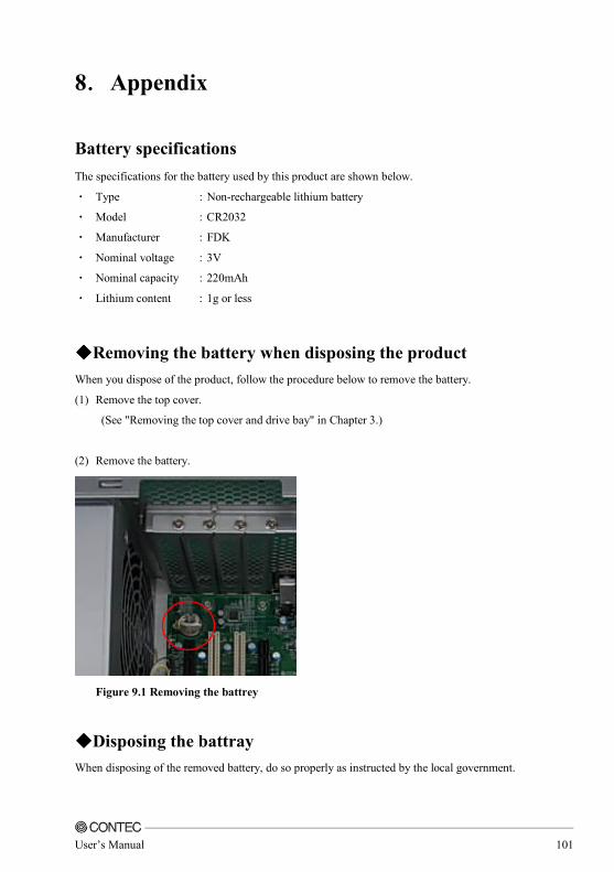
User’s Manual 101
8....Appendix
Battery specifications
The specifications for the battery used by this product are shown below.
・ Type :Non-rechargeable lithium battery
・ Model :CR2032
・ Manufacturer :FDK
・ Nominal voltage :3V
・ Nominal capacity :220mAh
・ Lithium content :1g or less
◆◆◆◆Removing the battery when disposing the product
When you dispose of the product, follow the procedure below to remove the battery.
(1) Remove the top cover.
(See "Removing the top cover and drive bay" in Chapter 3.)
(2) Remove the battery.
Figure 9.1 Removing the battrey
◆◆◆◆Disposing the battray
When disposing of the removed battery, do so properly as instructed by the local government.

102 User’s Manual
VPC-3000 Series User’s Manual
CONTEC CO.,LTD May 2015 Edition 3-9-31, Himesato, Nishiyodogawa-ku, Osaka 555-0025, Japan Japanese http://www.contec.co.jp/ English http://www.contec.com/ Chinese http://www.contec.com.cn/
All rights reserved. This product and this document are protected by copyright law. Unauthorized copying, duplication, reproduction, and tampering are prohibited.
[06172015] Management No NA04314 [06172015_Rev1.0] Parts No LYSY951


![Nexus vPC Print[1]](https://img.pdfslide.tips/doc/110x75/577d248d1a28ab4e1e9cba90/nexus-vpc-print1.jpg)