Embed Size (px)
Citation preview
� � � �� �
��������������������������������������������������������������������� � �
10/07 1
W9U-I Injectable Waterstop Trelleborg Ridderkerk BV
� � � �� �
��������������������������������������������������������������������� � �
10/07 2
Table of contents
Introduction 3
Installation/pouring procedure W9U-I waterstop 4
Injection procedure W9U-i waterstop 6
Rubberquality 9
Appendix 1 Product drawing W9UI-profile. 11
Appendix 2 Waterstop with injection pipe. 12
Appendix 3 Situation before pouring (injection system inside formwork). 13
Appendix 4 Situation before pouring (injection system through formwork). 14
Appendix 5 Situation during pouring. 15
Appendix 6 Injection 16
Appendix 7 Design application data 17 This brochure is composed by Trelleborg Ridderkerk, in case more information is needed please consult our sales or technical department at Ridderkerk (The Netherlands).
Trelleborg Ridderkerk B.V. P.O. Box 4007, 2980 GA Ridderkerk, The Netherlands.
Phone: +31 180 49 55 55 Telefax: +31 180 43 30 80 E-mail: [email protected] Internet: www.trelleborgbakker.com
� � � �� �
��������������������������������������������������������������������� � �
10/07 3
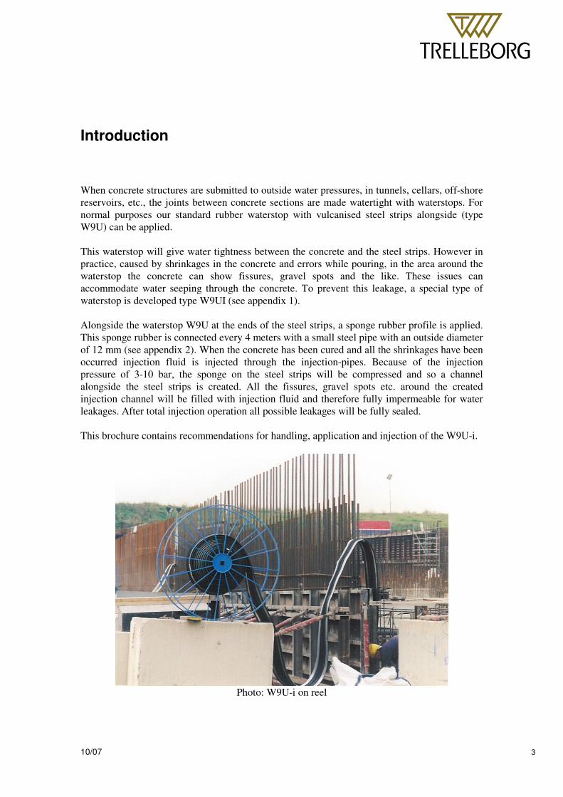
Introduction When concrete structures are submitted to outside water pressures, in tunnels, cellars, off-shore reservoirs, etc., the joints between concrete sections are made watertight with waterstops. For normal purposes our standard rubber waterstop with vulcanised steel strips alongside (type W9U) can be applied. This waterstop will give water tightness between the concrete and the steel strips. However in practice, caused by shrinkages in the concrete and errors while pouring, in the area around the waterstop the concrete can show fissures, gravel spots and the like. These issues can accommodate water seeping through the concrete. To prevent this leakage, a special type of waterstop is developed type W9UI (see appendix 1). Alongside the waterstop W9U at the ends of the steel strips, a sponge rubber profile is applied. This sponge rubber is connected every 4 meters with a small steel pipe with an outside diameter of 12 mm (see appendix 2). When the concrete has been cured and all the shrinkages have been occurred injection fluid is injected through the injection-pipes. Because of the injection pressure of 3-10 bar, the sponge on the steel strips will be compressed and so a channel alongside the steel strips is created. All the fissures, gravel spots etc. around the created injection channel will be filled with injection fluid and therefore fully impermeable for water leakages. After total injection operation all possible leakages will be fully sealed. This brochure contains recommendations for handling, application and injection of the W9U-i.
Photo: W9U-i on reel
� � � �� �
��������������������������������������������������������������������� � �
10/07 4
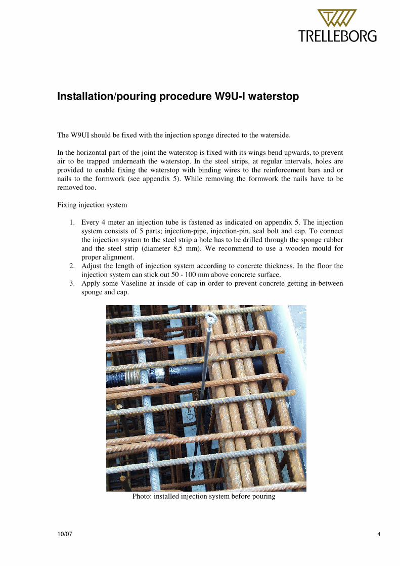
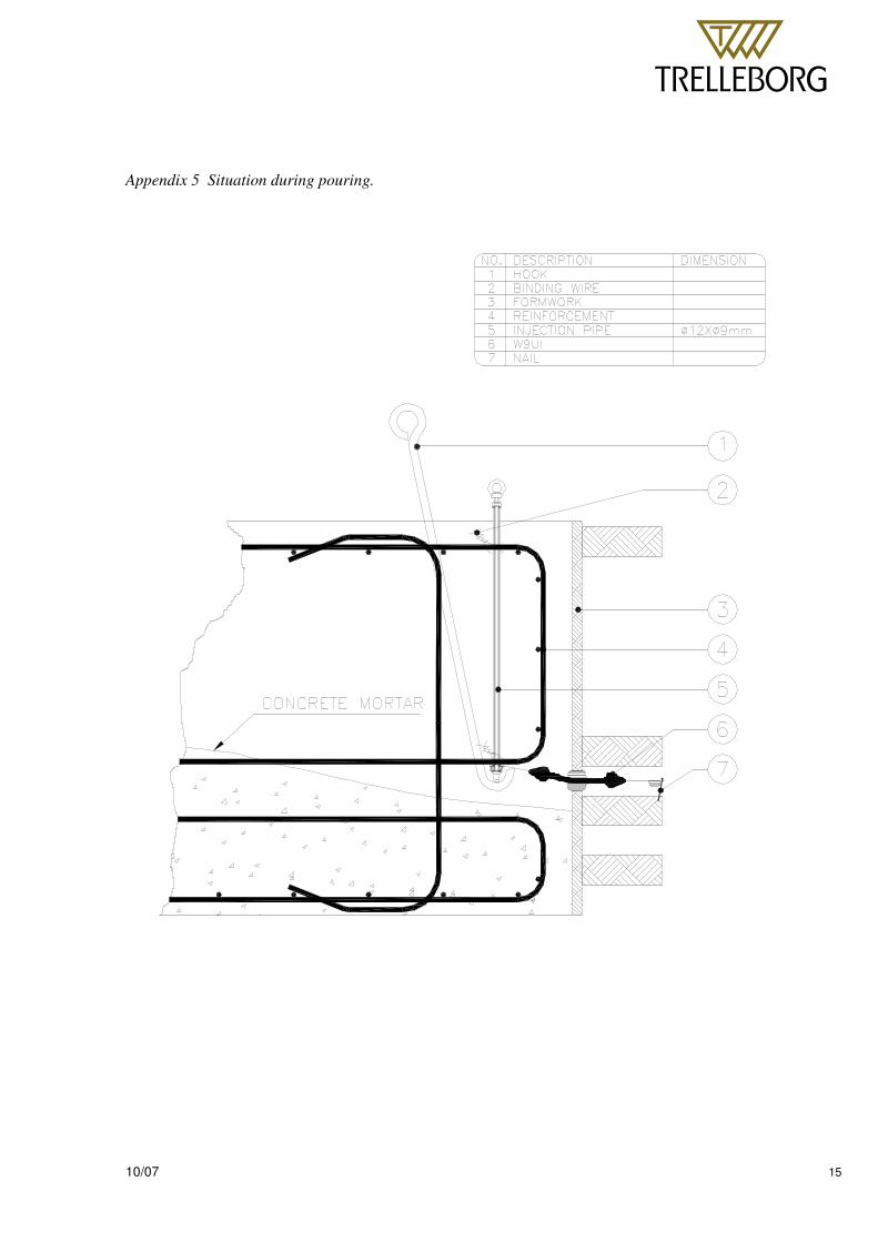
Installation/pouring procedure W9U-I waterstop The W9UI should be fixed with the injection sponge directed to the waterside. In the horizontal part of the joint the waterstop is fixed with its wings bend upwards, to prevent air to be trapped underneath the waterstop. In the steel strips, at regular intervals, holes are provided to enable fixing the waterstop with binding wires to the reinforcement bars and or nails to the formwork (see appendix 5). While removing the formwork the nails have to be removed too. Fixing injection system
1. Every 4 meter an injection tube is fastened as indicated on appendix 5. The injection system consists of 5 parts; injection-pipe, injection-pin, seal bolt and cap. To connect the injection system to the steel strip a hole has to be drilled through the sponge rubber and the steel strip (diameter 8,5 mm). We recommend to use a wooden mould for proper alignment.
2. Adjust the length of injection system according to concrete thickness. In the floor the injection system can stick out 50 - 100 mm above concrete surface.
3. Apply some Vaseline at inside of cap in order to prevent concrete getting in-between sponge and cap.
Photo: installed injection system before pouring
� � � �� �
��������������������������������������������������������������������� � �
10/07 5
4. Apply pin, pipe bolt and seal and connect cap to injection pin. 5. The bolt on the injection pin is tightened. By doing this the injection system is fixed on
the steel strip 6. The pin and pipe are fixed to the reinforcement bars at its proper height. At floor and
roof part it should be possible to move the injection system vertically in order to lift the sides of the water stop and so prevent trapped air.
7. Check the whole system before pouring 8. After pouring and hardening of the concrete the injection pins can be removed, and the
pipe can be shortened at concrete level. To prevent dirt getting into the pipe we recommend to close the pipe at the end.
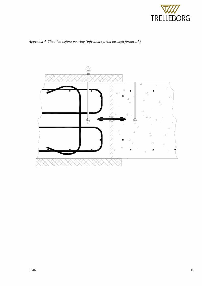
9. To apply the injection system in the walls and roof two procedures can be followed. The first option is to drill a hole through the casting (see appendix 4). The second option is to use a PVC cup. When using a cup the injection pin can be situated underneath the casting so the casting don’t have to be drilled (see appendix 3).
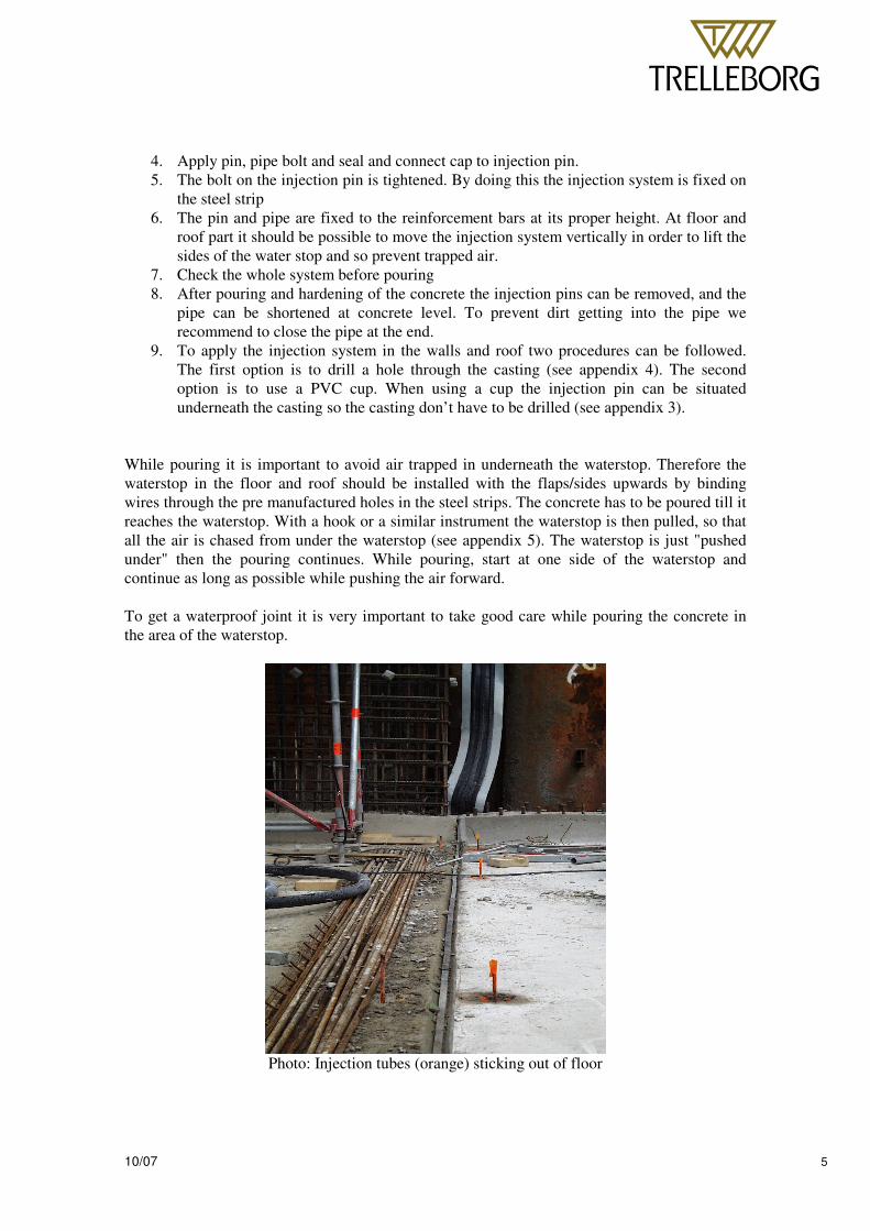
While pouring it is important to avoid air trapped in underneath the waterstop. Therefore the waterstop in the floor and roof should be installed with the flaps/sides upwards by binding wires through the pre manufactured holes in the steel strips. The concrete has to be poured till it reaches the waterstop. With a hook or a similar instrument the waterstop is then pulled, so that all the air is chased from under the waterstop (see appendix 5). The waterstop is just "pushed under" then the pouring continues. While pouring, start at one side of the waterstop and continue as long as possible while pushing the air forward. To get a waterproof joint it is very important to take good care while pouring the concrete in the area of the waterstop.
Photo: Injection tubes (orange) sticking out of floor
� � � �� �
��������������������������������������������������������������������� � �
10/07 6
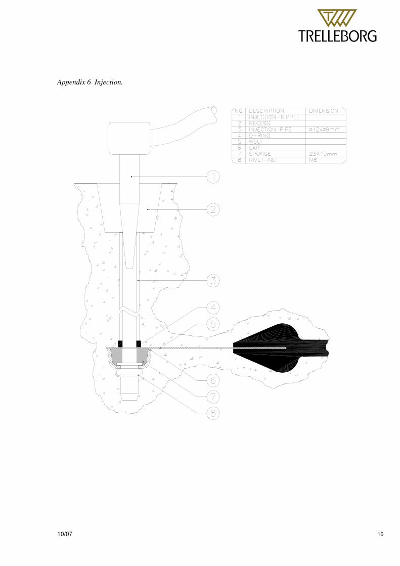
Injection procedure W9U-i waterstop Conditions If possible within one year after the pouring of the concrete the W9UI must be injected (see appendix 6). If the term will exceed one year, there is a possibility that the injection sponge will stick to the concrete. This will cause injection pressures to rise and injecting will be more difficult. The waterstops must be injected before the water pressure is activated on the concrete. If not the injection liquids mixes with water, changing the material quality and diminish the attachment and filling graduation with the concrete. For detailed information about the injection resin please contact our office. During injection there is a possibility injection fluid is getting into the joint and by doing this filling up the joint. To prevent this we advice to start the injection after (transport-) pre tension is applied on the tunnel elements. Injection can be done with a hand-pump (capacity up to 20 bar) during injection the pressure should not exceed 10 bar. The injection pressure varies, and depends on the attachment between sponge and concrete, the viscosity of the epoxy-resin and the injection distance between the injection pipes. Injection resins The Dutch public works prefer epoxy resin for preventive injection. In case of weak spots in the concrete for example caused by gravel spots, epoxy resin will recover and repair the concrete. Epoxy-polyurethane or polyurethane are regarded as less constructive, and are therefore not advised for preventive injection. Meanwhile these materials are less sensitive for use in a humid environment. For corrective purposes the use of these materials can be considered. Epoxy-resin
• Repairs the concrete • High compressive strength (select compressive strength > 85 N/mm2) • In general only to be applied in dry environment • Very solid after hardening
Specifications of Epoxy resin
• Epoxy resin free of solvents • Compressive strength > 85 N/mm2 • Viscosity < 150 GP at 25ºC
� � � �� �
��������������������������������������������������������������������� � �
10/07 7
Tools The injection tool has to be equipped with a clear manometer with a maximum range of 100 bar. Preferably the maximum pressure has to be adjustable. The fluids should be mixed mechanically according to regulations of supplier. Injection procedure The usage of injection resin depends on the number of gravel spots. Experience in practice result in a mean usage of 0,2 -0,4 litre/meter. 1. Check if the injection tubes are clean and dry. 2. Starting point of the injection should be in the middle of the floor of the tunnel. 3. Injection is done with two injection teams 4. Team A works to right side and team B works to left side, starting with the floor, then the
walls and finally the roof 5. One joint has to be injected in one phase, therefore make sure there are sufficient spare-
parts. 6. From the first injection point there has to be injected until the epoxy-resin is shown at the
next injection pipe (maximum pressure = 10 Bar). 7. As soon as the epoxy-resin leaves the next injection pipe, the first injection point should be
shut. Injection should go on from the second injection point. In case the epoxy-resin exceeds a pressure of 10 bar during 2 minutes one should also close this injection point and proceed from the next pipe.
8. When from the second injection point the epoxy-resin proceeds from the third injection point one should close the third injection pipe with a dome nut and go on with injection from the second point. All the following injection points from which the fluid is coming out should be shut. In case the proceeding epoxy-resin is coloured white one should wait with closing the injection pipe until the epoxy-resin has got its natural colour. The white colour shows that water is mixed with epoxy-resin.
9. As soon as the pressure will become higher as 10 Bar, close the injection point and proceed at the latest point where the fluid has been shown.
10. If leakages in the dilatation joint are suspected, injection should be stopped until the epoxy-resin is transformed into a gel. Thereafter the pressure can be increased slowly while checking if the leakage has stopped.
11. If not, extra holes should be drilled to the end of the waterstop and injection should be started from the extra holes with smaller distances.
12. If during injection-operation no leakages has appeared and the epoxy resin is not leaving the injection pipes one should drill at 1 meter from the last injection-pipe a hole to the sponge of the waterstop, and check if there’s epoxy-resin.
13. If not the injection should take place from the new drilled hole (after closing the injection pipe). If there is epoxy resin, drill a new hole at a distance of 1 meter and repeat the procedure.
14. After total operation the injection pipes can be shortened and the injection-space can be filled with mortar.
� � � �� �
��������������������������������������������������������������������� � �
10/07 8
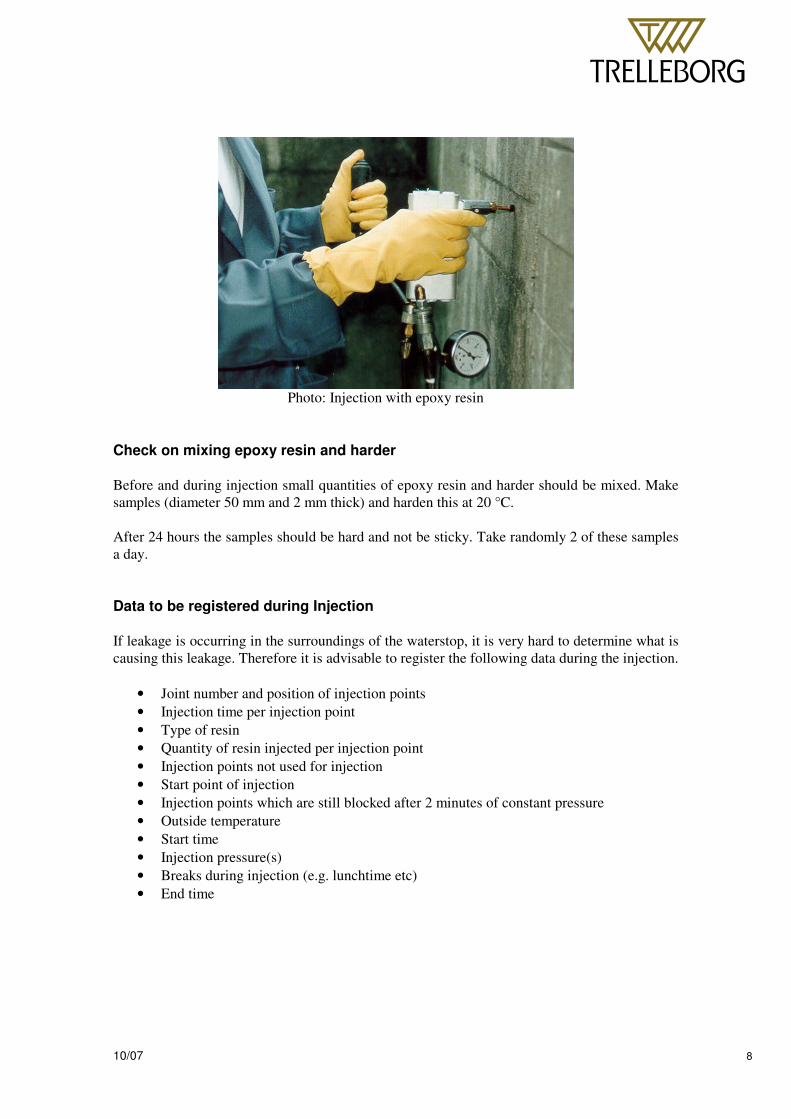
Photo: Injection with epoxy resin
Check on mixing epoxy resin and harder Before and during injection small quantities of epoxy resin and harder should be mixed. Make samples (diameter 50 mm and 2 mm thick) and harden this at 20 °C. After 24 hours the samples should be hard and not be sticky. Take randomly 2 of these samples a day. Data to be registered during Injection If leakage is occurring in the surroundings of the waterstop, it is very hard to determine what is causing this leakage. Therefore it is advisable to register the following data during the injection.
• Joint number and position of injection points • Injection time per injection point • Type of resin • Quantity of resin injected per injection point • Injection points not used for injection • Start point of injection • Injection points which are still blocked after 2 minutes of constant pressure • Outside temperature • Start time • Injection pressure(s) • Breaks during injection (e.g. lunchtime etc) • End time
� � � �� �
��������������������������������������������������������������������� � �
10/07 9
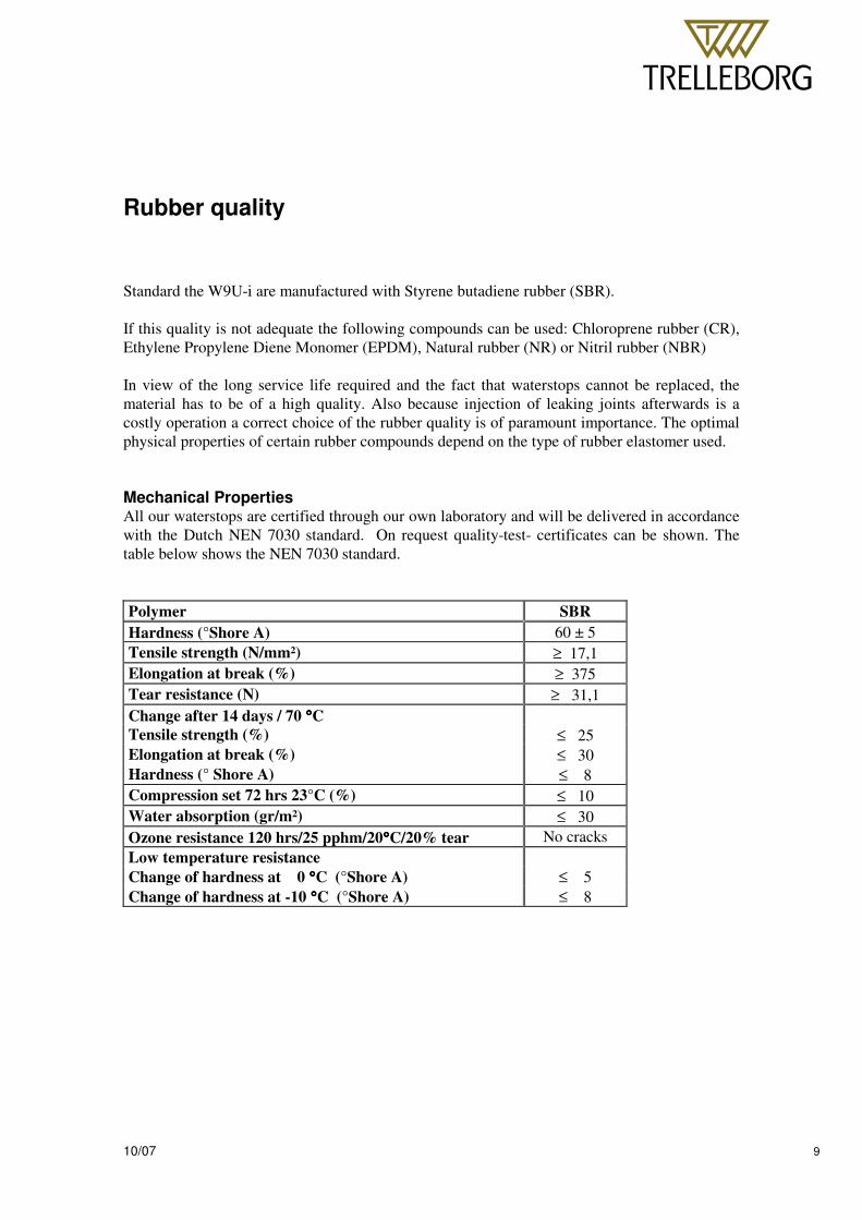
Rubber quality Standard the W9U-i are manufactured with Styrene butadiene rubber (SBR). If this quality is not adequate the following compounds can be used: Chloroprene rubber (CR), Ethylene Propylene Diene Monomer (EPDM), Natural rubber (NR) or Nitril rubber (NBR) In view of the long service life required and the fact that waterstops cannot be replaced, the material has to be of a high quality. Also because injection of leaking joints afterwards is a costly operation a correct choice of the rubber quality is of paramount importance. The optimal physical properties of certain rubber compounds depend on the type of rubber elastomer used. Mechanical Properties All our waterstops are certified through our own laboratory and will be delivered in accordance with the Dutch NEN 7030 standard. On request quality-test- certificates can be shown. The table below shows the NEN 7030 standard. Polymer SBR Hardness (°Shore A) 60 ± 5 Tensile strength (N/mm²) ≥ 17,1 Elongation at break (%) ≥ 375 Tear resistance (N) ≥ 31,1 Change after 14 days / 70 °°°°C Tensile strength (%) ≤ 25 Elongation at break (%) ≤ 30 Hardness (° Shore A) ≤ 8 Compression set 72 hrs 23°C (%) ≤ 10 Water absorption (gr/m²) ≤ 30 Ozone resistance 120 hrs/25 pphm/20°°°°C/20% tear No cracks Low temperature resistance Change of hardness at 0 °°°°C (°Shore A) ≤ 5 Change of hardness at -10 °°°°C (°Shore A) ≤ 8

� � � �� �
��������������������������������������������������������������������� � �
10/07 10
Chemical resistance In the table underneath the resistance against chemical influences is shown. This list is an indication to choose a rubber quality. The data is based on a temperature of 20 °C and concentrated solutions. In case of doubt don’t hesitate to contact us Quality SBR EPDM CR NR NBR Natural gas Moderate Moderate Excellent Moderate Excellent Petroleum Not Not Moderate Not Excellent Liquefied Ammonia Excellent Excellent Excellent Excellent Excellent ASTM Oil No. 1 Moderate Not Excellent Not Excellent ASTM Oil No. 2 Not Not Good Not Excellent ASTM Oil No. 3 Not Not Good Not Good Petrol Not Not Good Not Excellent
Brackish Water Excellent Excellent Excellent Excellent Excellent Diesel Not Not Good Not Excellent Kerosene Not Not Not Not Excellent Air from .. till .. ºCelsius -15 till 70 -20 till 110 -10 till 90 -40 till 70 -20 till 70 Mineral Oil Not Not Good Not Excellent Motor Oil Not Not Excellent Not Excellent Water till .. ºCelsius 70 110 70 70 70 Weather conditions/Ozone Moderate Excellent Excellent Moderate Moderate Seawater Moderate Excellent Excellent Moderate Excellent Sulphuretted hydrogen Not Good Moderate Not Good
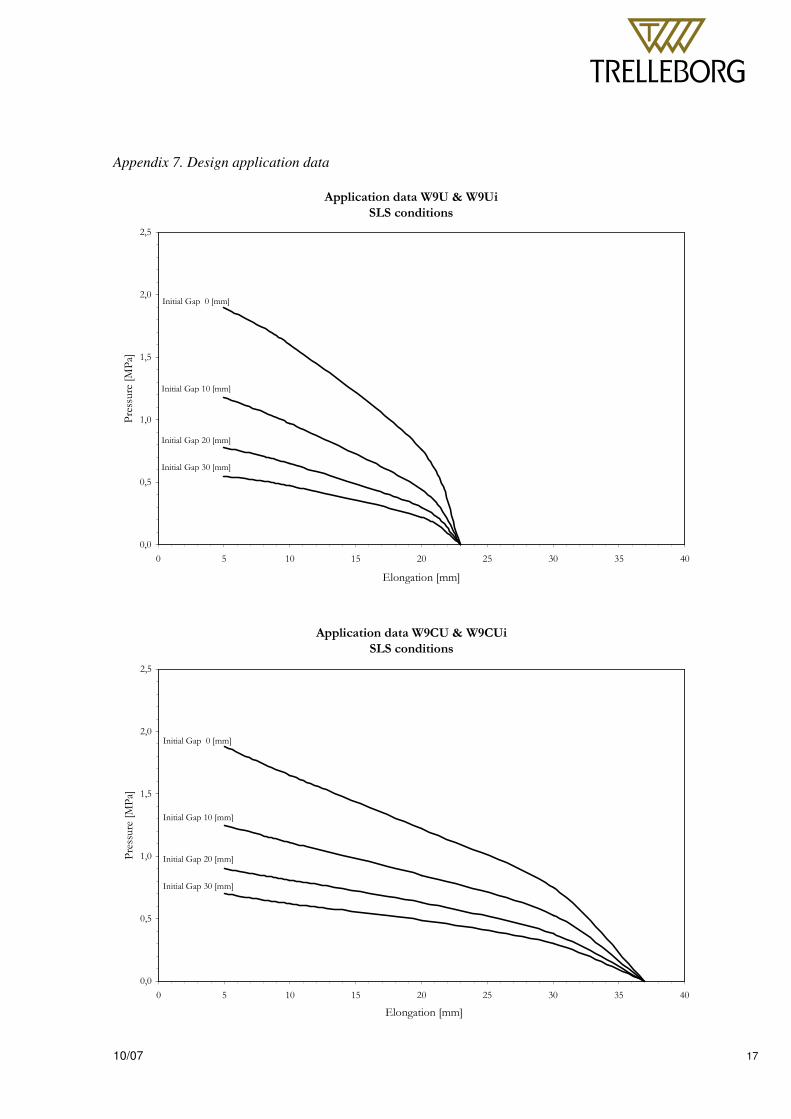
Area of application The final choice for a waterstop is made by desired movement and water pressure in head of water. Both cause a tension in the rubber. In appendix 7 you will find the design application data of the W9U-I. On the axis the maximum movements in X, Y, and Z direction are given at a certain pressure of the water (in meters water column).
Z
X
Y
� � � �� �
��������������������������������������������������������������������� � �
10/07 11
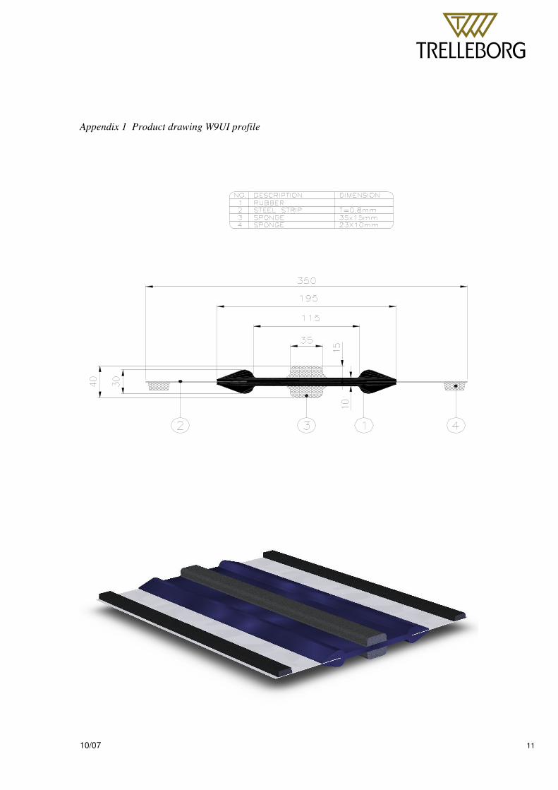
Appendix 1 Product drawing W9UI profile
� � � �� �
��������������������������������������������������������������������� � �
10/07 12
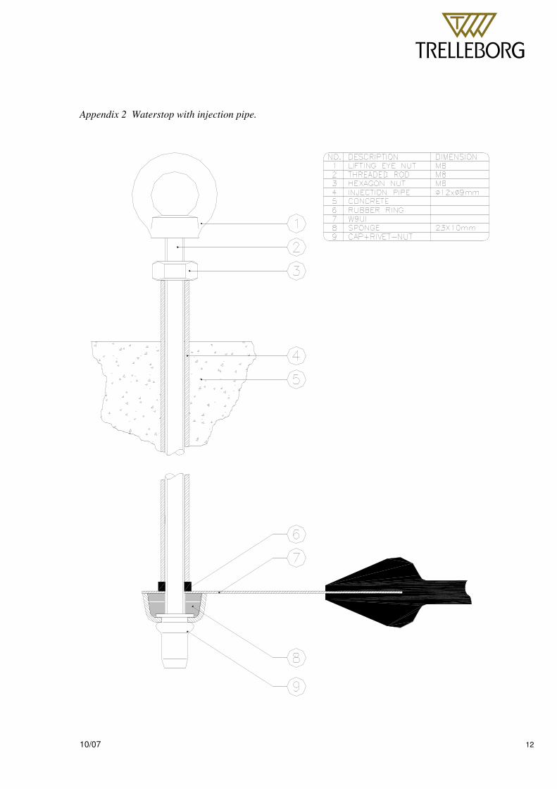
Appendix 2 Waterstop with injection pipe.
� � � �� �
��������������������������������������������������������������������� � �
10/07 13
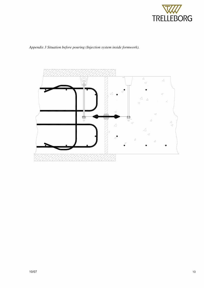
Appendix 3 Situation before pouring (Injection system inside formwork).
� � � �� �
��������������������������������������������������������������������� � �
10/07 14
Appendix 4 Situation before pouring (injection system through formwork)
� � � �� �
��������������������������������������������������������������������� � �
10/07 15
Appendix 5 Situation during pouring.
� � � �� �
��������������������������������������������������������������������� � �
10/07 16
Appendix 6 Injection.
� � � �� �
��������������������������������������������������������������������� � �
10/07 17
Appendix 7. Design application data
��������������� ��� ��
�����������
���
���
���
���
���
���
� � �� �� �� �� �� �� ��
��� ��������
������������ �
����� �� ���������
����� �� ���������
����� �� ���������
����� �� ���������
��������������� ���� ���
�����������
���
���
���
���
���
���
� � �� �� �� �� �� �� ��
��� ��������
������������ �
����� �� ���������
����� �� ���������
����� �� ���������
����� �� ���������