Embed Size (px)
Citation preview

ウォールコネクター (80A 単相) 設置マニュアル重要文書
日本国内向け仕様
CONECTOR DE PARED, 80A MONOFÁSICO MANUAL DE INSTALACIÓNESTE MANUAL ES DE ALTA IMPORTANCIAMercados Autorizados: Norteamérica, Japón
WALL CONNECTOR, 80A SINGLE PHASE INSTALLATION MANUAL
THIS MANUAL IS OF THE HIGHEST IMPORTANCE
Approved Markets: North America, Japan


About this Manual...........................2Communications Regulations.................................2Errors or Inaccuracies................................................2Copyrights and Trademarks....................................2
Safety Information..........................3Important Safety Instructions................................ 3Warnings.........................................................................3Cautions..........................................................................3Notes................................................................................4
Specifications...................................5
Features..............................................6Optional Circuit Ratings........................................... 6Self-Monitoring and Recovery................................6Power Outages.............................................................6Load Sharing.................................................................6
Planning Your Installation............ 7Minimum Requirements............................................ 7Service Wiring.............................................................. 7120V Above Ground................................................... 7Ground Connection.................................................... 7240V Single-Phase..................................................... 7208V 3-Phase Wye-Connected............................. 8240V Three-Phase Delta-Connected.................. 8277V Three-Phase Wye-Connected.....................9Determine the Circuit BreakerRequirements..............................................................10Choose the Best Location for the WallConnector.....................................................................10Installation Considerations...................................... 11
Check the Box Contents............. 13
Step-by-Step InstallationInstructions...................................... 15Tools and Materials Required................................ 15Overview of Installation Steps.............................. 15Install the Low Profile Bracket for Rearor Bottom Entry Wiring.......................................... 16
Install the Top Entry Bracket for TopEntry Wiring.................................................................17Prepare for Installation............................................ 18Connect the Wiring...................................................19Set the Operating Current......................................21Secure the Cover and Power Up.........................22
Troubleshooting............................23Reset..............................................................................26Questions?................................................................... 27
Appendix A: Testing forProper Operation..........................28
Appendix B: OptionalConnection for Load Sharing.. 29Daisy Chaining Multiple Wall Connectors....... 29Example of the Communication Wiring.......... 30
Charging EquipmentLimited Warranty...........................31General Terms............................................................. 31Limits of Liability.......................................................32Warranty Enforcement Laws andDispute Resolution................................................... 32
Contents

Communications Regulations
This device complies with Part 15 of the FCCrules and Industry Canada license-exempt RSSstandard(s). Operation is subject to thefollowing two conditions: (1) This device maynot cause harmful interference and (2) thisdevice must accept any interference received,including interference that may causeundesired operation.
Important: Changes or modifications tothis product not authorized by Teslacould void the FCC compliance.
Errors or Inaccuracies
To communicate any inaccuracies oromissions, or to provide general feedback orsuggestions regarding the quality of thismanual, send an email to:
Copyrights and Trademarks
All information in this document is subject tocopyright and other intellectual propertyrights of Tesla Motors, Inc. and its licensors.This material may not be modified,reproduced or copied, in whole or in part,without the prior written permission of TeslaMotors, Inc. and its licensors. Additionalinformation is available upon request. Thefollowing are trademarks or registeredtrademarks of Tesla Motors, Inc. in the UnitedStates and other countries:
All other trademarks contained in thisdocument are the property of their respectiveowners and their use herein does not implysponsorship or endorsement of their productsor services. The unauthorized use of anytrademark displayed in this document or onthe vehicle is strictly prohibited.
About this Manual
2

Important Safety Instructions
This document contains important instructionsand warnings that must be followed wheninstalling and maintaining the Wall Connector.
Warnings
Warning: Read all the instructions beforeusing this product.
Warning: This device should besupervised when used around children.
Warning: The Wall Connector must begrounded through a permanent wiringsystem or an equipment groundingconductor.
Warning: Do not install or use the WallConnector near flammable, explosive,harsh, or combustible materials,chemicals, or vapors.
Warning: Turn off input power at thecircuit breaker before installing orcleaning the Wall Connector.
Warning: Use the Wall Connector onlywithin the specified operatingparameters.
Warning: Never spray water or any otherliquid directly at the wall mounted controlbox. Never spray any liquid onto thecharge handle or submerge the chargehandle in liquid. Store the charge handlein the dock to prevent unnecessaryexposure to contamination or moisture.
Warning: Stop using and do not use theWall Connector if it is defective, appearscracked, frayed, broken, or otherwisedamaged, or fails to operate.
Warning: Do not attempt to disassemble,repair, tamper with, or modify the WallConnector. The Wall Connector is not userserviceable. Contact Tesla for any repairsor modification.
Warning: When transporting the WallConnector, handle with care. Do notsubject it to strong force or impact orpull, twist, tangle, drag, or step on theWall Connector, to prevent damage to itor any components.
Warning: Do not touch the WallConnector’s end terminals with fingers orsharp metallic objects, such as wire, tools,or needles.
Warning: Do not forcefully fold or applypressure to any part of the WallConnector or damage it with sharpobjects.
Warning: Do not insert foreign objectsinto any part of the Wall Connector.
Warning: Use of the Wall Connector mayaffect or impair the operation of anymedical or implantable electronic devices,such as an implantable cardiacpacemaker or an implantable cardioverterdefibrillator. Check with your electronicdevice manufacturer concerning theeffects that charging may have on suchelectronic devices before using the WallConnector.
Cautions
Caution: Do not use private powergenerators as a power source forcharging.
Caution: Incorrect installation and testingof the Wall Connector could potentiallydamage either the vehicle’s Batteryand/or the Wall Connector itself. Anyresulting damage is excluded from theNew Vehicle Limited Warranty and theCharging Equipment Limited Warranty.
Caution: Do not operate the WallConnector in temperatures outside itsoperating range of -22°F to 122°F (-30°Cto +50°C).
Safety Information
Safety Information 3

Notes
Note: Ensure that the Wall Connector’scharging cable is positioned so it will not bestepped on, driven over, tripped on, orsubjected to damage or stress.
Note: Do not use cleaning solvents to cleanany of the Wall Connector’s components. Theoutside of the Wall Connector, the chargingcable, and the connector end of the chargingcable should be periodically wiped with aclean, dry cloth to remove accumulation ofdirt and dust.
Note: Be careful not to damage the circuitboards or components during installation.
Safety Information
4

The maximum power rating for the Wall Connector is 20 kW or 80A at 250V AC single-phasepower. Your vehicle can charge from 200V to 277V single-phase power.
Description Specifications
Voltage and Wiring 277V AC single-phase: L1, neutral, and earth
208V or 240V AC single-phase: L1, L2, and earth
Current Maximum output: 80A, 72A, 64A, 56A, 48A, 40A, 36A,32A, 28A, 24A, 20A, 16A, 12A
Frequency 50 to 60 Hz
Cable Length 8.5' (2.6 m) and 24' (7.4 m)
Wall Connector Dimensions Height: 15.0" (380 mm)
Width: 6.3" (160 mm)
Depth: 5.5" (140 mm)
Top Entry Bracket Dimensions Height: 10.8" (275 mm)
Width: 15.1 " (130 mm)
Depth: 2.0" (50 mm)
Weight (including bracket) 20 lb (9 kg)
Operating Temperature -22°C to 122°C (-30°C to 50°C)
Storage Temperature -40°F to 185°F (-40°C to 85°C)
Enclosure Rating Type 3R
Agency Approvals cULus listed for United States and Canada under filenumber E354307, FCC Part 15.
Specifications
Specifications 5
Optional Circuit Ratings
Use a single-phase circuit breaker rated for100A per phase to obtain the fastest charging.In certain installation locations, this level ofpower isn’t readily available. Therefore, youcan adjust the circuit breaker rating on theWall Connector from 15A to 100A (refer to Setthe Operating Current on page 21).
Note: Tesla vehicles must be configured withoptional onboard charging equipment toaccept higher amperages. Contact Tesla if youhave questions about the onboard chargingcapabilities of your vehicle.
Self-Monitoring and Recovery
The Wall Connector has a ground monitoringcircuit that continuously checks for thepresence of a safe ground connection andautomatically recovers from faults. Manualtesting and resetting is not required.
Temporary problems such as ground faults orutility power surges are overcomeautomatically. If a residual current fault occursthat interrupts charging, the Wall Connectorautomatically tries to clear the fault and re-attempt charging.
If the problem is immediately sensed a secondtime, the Wall Connector waits 15 minutesbefore trying to charge. This process repeats 4times and if all attempts are unsuccessful,power is removed and no further attempts aremade. In this case, you will see a red error lighton the front panel (refer to Troubleshootingon page 23). It is recommended that whenyou see a red error light, you power off theWall Connector by switching off the upstreamcircuit breaker, and then power it back onagain.
The Wall Connector can alternatively be resetwhen a red error light is encountered usingthe RESET button (refer to Reset on page26).
Power Outages
If a power outage occurs, the Wall Connectorautomatically resumes charging when poweris restored. If the charging cable is pluggedinto the vehicle when power is restored, thelights blink and the unit does not energize thecharging cable for approximately 15 secondsto three minutes. This prevents the utility gridfrom experiencing a large surge when power isrestored and allows vehicles to begin drawingcurrent at random times, rather than all atonce.
Load Sharing
The Wall Connector provides the capability towire 4 Wall Connectors to a single circuit,giving vehicle owners reassurance that theycan charge multiple vehicles at home (refer to Appendix B: Optional Connection for LoadSharing on page 29).
Features
6

Minimum Requirements
Installation of the Wall Connector requires thatyou:
• Calculate the existing electrical load todetermine the maximum operatingcurrent.
• Calculate the distance to ensure minimalvoltage drop.
• Obtain any necessary permits from thelocal authority that has jurisdiction andconfirm that the follow-up inspection hasbeen scheduled by an electrician after theinstallation is complete.
• Use only copper conductors.• Use conductors that are sized in
accordance with local wiring regulations.The selected cable must be able to sustainperiods of constant load of up to 80A.
• Use protective devices. The circuitprotection device chosen mustincorporate a suitable residual-currentdevice (RCD) and overcurrent protectionin relation to the electrical load selected.
Note: Consult with an electrician to ensurethat the installation meets local regulations.
Service Wiring
120V Above Ground
Warning: The Wall Connector is a single-phase device. Do not connect all threephases of a three-phase feed.
Warning: Before installing the WallConnector, identify the type of utilityservice connection available on site. If youare unsure about the type of connectionavailable at the service panel, consult anelectrician, or contact Tesla for assistance.
Caution: The two phases used must eachmeasure 120V to neutral. Earth groundmust be connected to neutral at only onepoint, usually at the breaker panel.
Caution: If a 240V three-phase feed isfrom a Delta-connected secondary, theleg used must have a center tap. Thiscenter tap must be grounded. Only thetwo phases on either side of the center-tapped leg can be used.
Only three wires are connected, but care mustbe taken that the service transformersecondary connection is definitely known, andthat the three wires from the main circuitbreaker panel are correctly connected andlabeled. The illustrations shown are the mostcommonly used wiring formats.
Note: The L1, L2, and ground outputs labeledon the illustrations correspond to the inputson the Wall Connector.
Ground Connection
Always connect the Neutral at the service toEarth Ground. Ground fault protection is notpossible unless the Neutral (center tap on theservice transformer) is connected to an EarthGround. If ground is not provided by theelectrical service, you must install a groundingstake nearby. the grounding stake must beconnected to the ground bar in the mainbreaker panel, and Neutral connected toGround at that point.
240V Single-Phase
L2
L1
120V
120V
GND
240VNEUTRAL(NOT USED)
Note: Illustrations in this document are fordemonstration purposes only.
Planning Your Installation
Planning Your Installation 7

208V 3-Phase Wye-Connected
With a Wye-connected secondary, any two ofthe legs can be used to provide 208V to theWall Connector. For example, L1 and L2, or L1and L3, or L2 and L3. The two used phasesmust each measure 120V to neutral.
Note: A current-carrying neutral is notrequired.
120V 208V
120V
L1
NEUTRAL(NOT USED)
L3 (NOT USED)
L2 (NOT USED)
GND
Caution: The unused leg (L3 in theillustration) must remain open. Do notconnect to a neutral bar, or to earthground.
Caution: The center point of the threephases (normally used as neutral) mustbe grounded to earth at only one point.This is usually at the breaker panel.
240V Three-Phase Delta-Connected
With the delta connection, one leg must becenter tapped, and only the two phases oneither side of the center tap can be used. Thetwo used phases must each measure 120V toneutral.
Consult the transformer manufacturer’sliterature to verify that the single leg cansupply the required power.
Note: The Wall Connector’s contactor closesonly if it detects the presence of an earthground wire connected to a neutral point onthe transformer secondary.
L1
L2
GND
120V
120V
240V
L3 (NOT USED)
NEUTRAL(NOT USED)
Caution: The third line (L3 in theillustration) of the delta is 208V, withrespect to neutral, and is sometimesreferred to as a “stinger.” Do not use thisthird line.
Caution: Do not use a three-phase delta-connected transformer secondarywithout a center tap on one leg. Noneutral point is available for the requiredearth ground connection.
Planning Your Installation
8

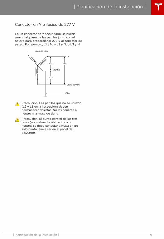
277V Three-Phase Wye-Connected
With a Wye-connected secondary, any legalong with neutral can be used to provide277V to the Wall Connector. For example, L1and N, or L2 and N, or L3 and N.
277V 480V
277V
L1
NEUTRAL
L3 (NOT USED)
L2 (NOT USED)
GND
Caution: The unused legs (L2 and L3 inthe illustration) must remain open. Do notconnect to neutral or to earth ground.
Caution: The center point of the threephases (normally used as neutral) mustbe grounded to earth at only one point.This is usually at the breaker panel.
Planning Your Installation
Planning Your Installation 9

Determine the Circuit BreakerRequirements
To determine the type of upstream circuitbreaker you need, examine the distributionpanel or circuit breaker box to identify theamperage available at the installation site.
The Wall Connector has an internal rotaryswitch that allows you to adjust its operatingcurrent (refer to Set the Operating Current onpage 21). The circuit breaker should be ratedfor the continuous current of: 12, 16, 20, 24, 28,32, 36, 40, 48, 56, 64, 72, and 80A.
Choose the Best Location for theWall Connector
Determine the parking location of the vehicleto ensure that the charge cable reaches thecharge port.
• In an enclosed garage, typically on thevehicle's charge port side.
• In a well-ventilated area. Avoid installationin an enclosed box, or adjacent to hotappliances.
Note: The Wall Connector is approved foroutdoor use. Protection from rain isrecommended but not required.
Planning Your Installation
10

Installation Considerations
Three methods are available to install the Wall Connector. The location of the conduit determineswhich installation method to follow. If the conduit runs along the floor or low on the wall, use thebottom entry configuration. If the conduit comes from inside the wall, use the rear entryconfiguration. If the available conduit comes from the ceiling, use the top entry installation.
Note: Throughout the manual, “conduit” is used as the standard term for the protective tubingthat houses the service wiring. In regions where conduit is not used (Europe for example), a cablecomprised of service wiring enclosed in a protective jacket may be substituted for conduit ifallowed by local regulations.
Here are some additional guidelines:
• Conduit openings are sized for 1" (25 mm) conduit.• Conduit needs to be metal and flame retardant.• Use an appropriate circuit breaker.• To keep the housing weatherproof, use cable glands.• Use a UL approved conduit hub, Eaton HUB3 or equivalent is recommended.
Bottom or Rear Entry
Planning Your Installation
Planning Your Installation 11

Top Entry
Planning Your Installation
12

The shipping box contains parts for all installation methods, as well as this manual. If any parts aredamaged or missing, contact Tesla (refer to Questions? on page 27).
Note: Not shown is the supplied cardboard template.
1 2 3 4
5 6 7 8 9
10 11 12 13 14
Item Description (Quantity)
1 Wall Connector
2 Top entry bracket*
3 Low profile bracket **
4 Low profile bracket screws (2) **
5 Bottom or rear entry power conduit plug
6 Bottom or rear entry signal conduit plug
7 Top entry signal conduit plug*
8 Top entry power conduit plug*
9 Bottom conduit sealing gasket*
10 Top bracket-to-housing screw covers (2)
11 Bottom bracket-to-housing screw covers (2)
Check the Box Contents
Check the Box Contents 13
Item Description (Quantity)
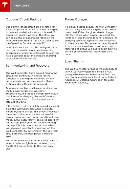
12 Bottom bracket-to-housing screws (2)
13 Top bracket-to-housing screws (2)
14 Top entry bracket mounting screws (2)*
* Items used in only top entry installations.
** Items used in only bottom or rear entry installations.
Check the Box Contents
14

Tools and Materials Required
Before installing the Wall Connector, gather the following tools and materials:
• Pencil or marker
• Hole punch (optional, to push through cardboard template)
• Wire stripper
• Voltmeter or digital multimeter (to measure AC voltage at the installation site)
• Phillips screwdriver
• Small flathead screwdriver
• Large flathead screwdriver (optional, to remove plastic knock-outs)
• T20 security pin Torx driver
• T10 Torx driver
• M20 and M32 cable glands (also known as sealing hubs)
• Ferrules (the diameter of the ferrule depends on the diameter of the power wiring and the
construction)
• Wiring (use twisted pair communication cable, for a maximum of 49 ft (15 m) between Wall
Connectors)
Note: Tesla recommends that you use a shielded cable to limit potential interference.
• Level
• Machine drill
Overview of Installation Steps
Warning: After you run service wiring to the installation site using metal flame retardantconduit, install the appropriate upstream circuit breaker, TURN OFF AND VERIFY POWER ISOFF BEFORE CONTINUING.
Then follow these steps to install the Wall Connector:
• Install the Low Profile Bracket for Rear or Bottom Entry Wiring on page 16• Install the Top Entry Bracket for Top Entry Wiring on page 17• Prepare for Installation on page 18• Connect the Wiring on page 19• Set the Operating Current on page 21• Secure the Cover and Power Up on page 22
Step-by-Step Installation Instructions
Step-by-Step Installation Instructions 15

Install the Low Profile Bracket forRear or Bottom Entry Wiring
Use the low profile bracket, shown below, towire the Wall Connector from the rear orbottom.
1. Use the low profile bracket as a guide tomark the location on the wall for themounting screws.
• Use a level to ensure that the marksare perfectly vertical.
• Space the holes 4.5" (114 mm) apart.
• For U.S.A. installations, position thebracket so that the Wall Connector islocated at a maximum of 60" (150cm)from floor level. The minimumheight is 18" (45 cm) if mountingindoors, and 24" (60 cm) if mountingoutdoors.
• If using rear entry conduit, use at leastone set of the edge mounting holes sothat the conduit does not interferewith the wall stud.
• If using bottom entry conduit, use thecenter two mounting holes.
Note: Ensure that the minimum andmaximum height of the bracket is carefullyselected. It should be installed out of theway of any reasonably foreseeableimpacts.
2. Attach the bracket using fasteners thatare appropriate for the type of wallmaterial, drilling pilot holes if necessary.Use the supplied screws only if mountingthe bracket directly to a wooden stud. Ifmounting to another type of wall (hollow,masonry, etc.), use fasteners that are longenough to securely anchor the WallConnector and can hold at least 80 lb (36kg).
Step-by-Step Installation Instructions
16

Install the Top Entry Bracket for TopEntry Wiring
The top entry bracket enables you to route theservice wiring into the Wall Connectorenclosure from the top of the enclosure, asshown below.
1. Use the cardboard template and a level asa guide to mark the location on the wallfor the mounting screws.
• Use a level to ensure that the marksare perfectly vertical.
• Space the holes 6.1" (155 mm) apart.• Position the bracket so that the Wall
Connector is located at a maximum of60" (150 cm) from floor level. Theminimum height is 18" (45 cm) ifmounting indoors, and 24" (60 cm) ifmounting outdoors.
Note: Ensure that the minimum andmaximum height of the bracket is carefullyselected. It should be installed out of theway of any reasonably foreseeableimpacts.
2. (Optional) There are two additionalmounting holes. To use these holes, use aflat-head screwdriver to knock-out theplastic that is closing the holes. Theseholes are spaced 2.75" (70 mm) apart.
3. Attach the bracket using fasteners thatare appropriate for the type of wallmaterial, drilling pilot holes if necessary.Use the supplied screws only if mountingthe bracket directly to a wooden stud. Ifmounting to another type of wall (hollow,masonry, etc.), use fasteners that are longenough to securely anchor the WallConnector and can hold at least 80 lb (36kg).
Step-by-Step Installation Instructions
Step-by-Step Installation Instructions 17

Prepare for Installation
Follow these instructions to remove the coverand route the service wiring into the WallConnector.
1. Use a T10 Torx driver to remove the screwat the bottom of the outer cover. Carefullydisengage the snaps on the sides and topusing a flathead screwdriver andcompletely remove the cover. Save thescrew and cover for reassembly.
2. Use a T20 security pin Torx driver toremove the six screws on the sealingcover. Carefully remove the sealing coverand disconnect the ribbon cable. Save thescrews and cover for reassembly.
Caution: Do not allow the sealingcover to hang from the ribbon cable.Doing so can damage the ribboncable or its connectors.
3. For top entry configuration, install thewiring to the terminal block in the topentry bracket as shown in Connect theWiring on page 19, then return to thissection and proceed to the next step. Forback or bottom entry configurations, skipto the next step.
4. Place and hold the Wall Connector on thebracket, ensuring that all four mountingtabs are properly aligned.
5. Use a T20 Torx driver to install the twotop housing mounting screws. Push thecosmetic screw covers into place.
6. Use a T20 Torx driver to install the twobottom housing mounting screws. Pushthe cosmetic screw covers into place.
Step-by-Step Installation Instructions
18

Connect the Wiring
Note: Consult with your local electrician orrefer to your local code for proper wire sizingappropriate for the currents in your WallConnector.
Note: It is the installer's responsibility toidentify whether additional grounding isrequired to ensure that local regulations aremet. Grounding must be installed at the powersource and not at the cable entry to the WallConnector.
Warning: Do not connect service wiringuntil you have read and fully understandthe concepts described in Service Wiringon page 7. If you are uncertain about thetype of power available at the servicepanel, consult an electrician, or contactTesla for assistance.
1. Turn off the power.
Warning: RISK OF ELECTRIC SHOCK!Before continuing, use a voltmeter toensure the power is off by confirmingthat NO VOLTAGE is present at theservice wiring or terminals.
2. For top entry installation, pull the servicewiring into the top entry bracket or theWall Connector. Use a 1" (25 mm) cablegland to seal the power conduit or cable.For 80A operation, use 2AWG 194°F(90°C) rated copper wire or follow localregulations.
Note: The meaning of wiring colors mightvary from country to country. Follow allapplicable national and local regulationsconcerning wiring color codes.
The following illustration shows anexample of the wiring for the top entrybracket.
The following illustration shows anexample of the wiring for the low profilebracket.
3. Strip the service wires going to theterminal block on the top entry bracket3/4" (18 mm). Ferrules are recommended.
Note: For top entry installation, theflexible pre-installed wires that go fromthe top entry bracket to the housing arealready terminated and do not need to bestripped.
Step-by-Step Installation Instructions
Step-by-Step Installation Instructions 19

4. Lead the preconnected service wires inthe main housing 3/8" (10 mm) andconnect the preconnected service wires tothe terminal block with L1 (or line), L2 (orneutral), and ground wires going to thelocations shown in the followingillustration.
Caution: Cut each of the wire strandsand insert them fully into each theterminal block.
Note: To ensure proper operation, verifythat neutral is connected to the neutralline inside the circuit breaker box or themain electrical panel.
5. Tighten the terminal block to therecommended torque:
• 35 in-lb (4.0 N-m) for the terminalblock on the top entry bracket.
• 33 in-lb (3.8 N-m) for the terminalblock in the main housing.
• 18 in-lb (2.0 N-m) for the groundterminal block in the main housing.
6. Check for miswiring using a multimeterand verify that there are no shorts beforeturning the upstream circuit breaker ON.
Step-by-Step Installation Instructions
20

Set the Operating Current
Follow these instructions to configure the DIPswitch. The following illustration shows anenlarged view of the DIP and rotary switches.
Warning: Power MUST remain OFF beforesetting or changing the DIP or rotaryswitches. Changing these switches withthe power ON will not be recognized bythe system and is dangerous due to therisk of electric shock.
1. Turn OFF power.2. Use a non-conductive object (such as a
plastic pen) to adjust the DIP switchsettings:
• Switch Position 1:
• For a Line to Line connection(240V) set the DIP switch DOWN.
• For an Line to Neutral connection(277V), set the DIP switch UP (theON position).
Warning: Before you set the DIPswitches, confirm which type ofinput service the utility provides.
• Switch Position 2:
• DIP Switch Position 2 shouldalways be in the UP position.
DIP Switch Up (ON) Down
Position 1 Line toNeutral(277V)
Line to Line(240V)
Position 2 Normal NotApplicable
3. Set the rotary switch for the appropriatecurrent setting supported by your circuitbreaker. Typical circuit breaker ratings are:15A, 20A, 25A, 30A, 35A, 40A, 45A, 50A,60A, 70A, 80A, 90A, and 100A.
Use a small flathead screwdriver to adjustthe rotary switch to the appropriate circuitbreaker capability setting. Thecorresponding rotary switch settings forthe typical circuit breakers are shown inthe following table:
RotarySwitchPosition
MaximumOutputCurrent
CircuitBreaker
0 Test mode N/A
1 12A 15A
2 16A 20A
3 20A 25A
4 24A 30A
5 28A 35A
6 32A 40A
7 36A 45A
8 40A 50A
9 48A 60A
A 56A 70A
B 64A 80A
C 72A 90A
D 80A 100A
E Not a validselection
N/A
F Slave mode N/A
4. Reattach the ribbon cable to the sealingcover.
5. Reinstall the sealing cover. Use a T20security pin Torx driver to lightly securethe sealing cover by installing only the topscrew.
6. Turn ON power.7. If the installation is successful, the LEDs
briefly sequentially illuminate green with apattern that ends with the top green LEDstaying solid ON. If there is a solid orflashing red LED, refer to Troubleshootingon page 23 and resolve the error beforeyou continue.
Step-by-Step Installation Instructions
Step-by-Step Installation Instructions 21

Note: To review the pattern of blinkinglights, press and hold the RESET buttonfor 5 seconds.
8. Turn OFF power.9. Write the contact information of the
installer on the label on the inside of theWall Connector.
Secure the Cover and Power Up
1. Use a T20 security pin Torx driver toinstall the remaining screws on the sealingcover. Ensure that the cover is properlyaligned before fully tightening the screws.
2. Attach the outer cover to the sealingcover starting with the latch at the top.Engage the snaps on the sides and alignthe mounting tab with the housing at thebottom.
3. Use a T10 Torx driver to install the screwthat secures the bottom of the outer coverto the housing.
4. Close any unused openings with powerand signal conduit plugs.
Note: There should not be any visibleopenings to the inside of the WallConnector, and the Wall Connector shouldbe completely sealed from theenvironment.
5. Turn ON the power. The installation iscorrect if the LEDs go through a sequenceof flashing, ending with the top GreenLEDs staying solidly ON. If there is a solidor flashing Red LED, resolve the errorbefore you continue (refer to Troubleshooting on page 23).
Note: To review the pattern of blinkinglights, press and hold the Reset button for5 seconds.
6. Attempt to charge the vehicle to ensurethe Wall Connector is operating correctlyand charging at the selected operatingcurrent. For instructions on how to charge,refer to the owner information providedwith the vehicle.
Step-by-Step Installation Instructions
22

GreenLights
YellowLight
Red Light Auto-Retry What it Means What to Do
Top lighton
Off Off Notapplicable
Power on. The WallConnector ispowered and instandby but notcharging thevehicle.
Not applicable.
Streaminglights
Off Off Notapplicable
The Wall Connectoris charging thevehicle.
Not applicable.
Streaminglights
1 flash Off Notapplicable
Charging current isreduced due to hightemperaturedetected in theVehicle Connector.
Make sure the VehicleConnector (chargehandle) is fullyinserted into thecharge inlet in the car,is not covered byanything, and no heatsource is nearby. If theproblem continueswith normal ambienttemperatures (under100°F or 38°C),contact Tesla.
Streaminglights
2 flashes Off Notapplicable
Charging current isreduced due to hightemperaturedetected in the wallplug or on the inputterminals to theWall Connector.
If a wall plug is used,make sure that it isfully inserted into thereceptacle, it is notcovered by anything,and no heat source isnearby. If the WallConnector is wireddirectly to the wallsource, make sure thatthe Wall Connector isnot covered byanything, and no heatsource is nearby. If theproblem continueswith normal ambienttemperatures (under100°F or 38°C),contact Tesla.
Streaminglights
3 flashes Off Notapplicable
Charging current isreduced due to hightemperaturedetected inside theWall Connector.
Make sure the WallConnector is notcovered by anythingand no heat source isnearby. If the problemcontinues with normalambient temperatures(under 100°F or38°C), contact Tesla.
Troubleshooting
Troubleshooting 23

GreenLights
YellowLight
Red Light Auto-Retry What it Means What to Do
Off Off 1 flash After 15minutes andup to 4times
Groundfault. Current isleaking through anunsafe path.Possible Line toground or Neutralto ground fault.
Disconnect the handlefrom the car.Reconnect and tryagain. If the problempersists, turn OFF thecircuit breakerservicing the WallConnector and wait 10seconds. Turn ON thecircuit breaker and tryagain. If the problempersists, contact Tesla.
Off Off 2 flashes After 1minute andup to 4times
No groundconnectiondetected in the WallConnector.
Make sure the WallConnector is properlygrounded. If uncertain,consult yourelectrician for propergrounding at yourcircuit breaker orpower distributionbox and for properconnection to the WallConnector.
Off Off 3 flashes No Input miswired:possibly Line andNeutral areswapped.
The input wiringbetween the wallpower and the WallConnector has beenimproperly installed.Consult yourelectrician.
Off Off 4 flashes After 1minute andup to 4times
Over or undervoltage protection.
Consult yourelectrician for propervoltage on the circuitbreaker that servicesthe Wall Connector.
Off Off 5 flashes After 1minute retry(no limit onretries)
Over currentprotection.
Turn down the chargecurrent setting in thevehicle. If the problempersists and theattached vehicle ismanufactured byTesla, contact Tesla.
If the problem persistsand the attachedvehicle is a non-Teslavehicle, contact theoriginal manufacturer.
Troubleshooting
24
GreenLights
YellowLight
Red Light Auto-Retry What it Means What to Do
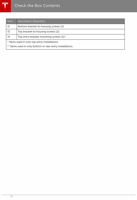
Off Off 6 flashes After 1minute retry(no limit onretries)
Pilot fault: The pilotlevel is incorrect
Plug the vehicle intoanother WallConnector if possibleor plug the vehicleinto a MobileConnector suppliedwith the vehicle; If theproblem persists,contact Tesla.
Top lighton
Off 1 flash No Over temperatureprotection (latch-off)
Make sure the WallConnector, vehicleconnectors, and wallplug (if used) are notcovered by anythingand there is no heatsource nearby. If theproblem continueswith normal ambienttemperatures (under100°F or 38°C),contact Tesla.
Top lighton
Off 2 flashes No Non-Tesla vehicleattemptingconnection to non-compatible inputdistribution.
Compatible inputdistributions are:single-phasedistribution or 400V,three-phasedistribution.
Top lighton
Off 3 flashes No Incorrect rotaryswitch setting.
Consult yourelectrician.
Top lighton
Off 4 flashes NotApplicable
Circuit BreakerSharing Network:More than one WallConnector is set toMaster.
Set one of the WallConnectors to Slave.
Top lighton
Off 5 flashes NotApplicable
Circuit BreakerSharing Network:More than threeWall Connectors areset to Slave.
Move one or moreWall Connectors to adifferent circuit anddisconnect it from thisCircuit BreakerSharing Network.
Top lighton
Off 6 flashes NotApplicable
Circuit BreakerSharing Network:The networked WallConnectors havedifferent maximumcurrent capabilities.
Contact Tesla.
Troubleshooting
Troubleshooting 25

GreenLights
YellowLight
Red Light Auto-Retry What it Means What to Do
Off Off Solid red No Wall Connectorhardware failure.Possible failuresinclude thefollowing:
• Contactor failed• Self test failed
in CCIDcircuitry
• Other possiblehardwarefailures mightbe MCU,3V3output, orthe thermalsensor.
Contact Tesla.
Reset
If a fault causes a RED error light to illuminate or flash and the fault condition is corrected, you canuse the RESET button to reset the Wall Connector to return to proper operation.
1. Press the RESET button for two to three seconds. When the top light changes from RED toGREEN, release the RESET button. In this reset method, the fault message is cleared but theWall Connector is not forced to reboot.
2. In a rare situation, you might need to force the Wall Connector to reboot without recycling theinput power. Press the RESET button for five seconds. When the top light changes from REDto GREEN, release the RESET button. The top light should continue to illuminate GREEN. If thelight returns to flashing RED, the fault state has not been corrected.
Troubleshooting
26

Questions?
• United States and Canada:
• [email protected]• +1-650-681-6133
• Mexico
• [email protected]• +1-877-798-3752
Troubleshooting
Troubleshooting 27

1. Turn OFF power.
Warning: RISK OF ELECTRIC SHOCK!Before continuing, use a voltmeter toensure the power is off by confirmingthat NO VOLTAGE is present at theservice wiring or terminals.
2. Use a non-conductive object (such as aplastic pen) to adjust the DIP switches tothe appropriate grid setting and circuitbreaker sharing setting (refer to Set theOperating Current on page 21).
3. Use a small flathead screwdriver to set therotary switch to position "0" to put theWall Connector into Test Mode.
Warning: Power MUST remain OFFbefore setting or changing the DIP orrotary switches. Changing theseswitches with the power ON will notbe recognized by the system and isdangerous due to the risk of electricshock.
4. Reattach the ribbon cable to the sealingcover.
5. Use a T20 security pin Torx driver tolightly secure the sealing cover byinstalling only the top screw.
6. Turn ON the circuit breaker.7. Watch for any Red LEDs to be ON after a
sequence of LED display; if so, there is afault in the installation.
8. Listen for the click of a contactor or relayclosing and opening.
9. Watch for Green streaming LEDs (for 5seconds).
LEDs will revert to top Green LED ON andRed LEDs flashing (3 times).
Note: To review the pattern of blinkinglights, press and hold the Reset button for5 seconds.
10. Turn OFF the circuit breaker.11. Remove the sealing cover screw, sealing
cover. Disconnect the ribbon cable.
Caution: Do not allow the sealingcover to hang from the ribbon cable.Doing so can damage the ribboncable or its connectors.
12. Reposition the rotary switch to theappropriate setting (refer to Set theOperating Current on page 21).
13. Reattach the ribbon cable to the sealingcover.
14. Replace all the screws and reinstall theouter cover (refer to Secure the Cover andPower Up on page 22).
Appendix A: Testing for Proper Operation
28

The Wall Connector includes a featurewhereby Wall Connector to Wall Connectorcommunication allows you to split themaximum available load over a maximum of 4Wall Connectors. The wire used for this localnetwork must share the main power cableconduit or be housed in a separate conduit.
You can connect the Wall Connectors in seriesin a daisy chain configuration.
Note: Take additional precautions intoconsideration to prevent water ingress at theWall Connectors when installing themoutdoors.
Note: Consult with an electrician to ensurethat the installation meets local regulations.
Daisy Chaining Multiple WallConnectors
Each Wall Connector has one terminal blockdedicated for the communication wiring asshown below. The left hand side of theterminal block is the input terminal and theright hand side the output terminal.
1. Form a daisy-chained network byconnecting the cables from OUT to IN and
always from positive to positive andnegative to negative between each of theparticipating Wall Connectors (refer to Example of the Communication Wiring onpage 30).
• The signal wires between each WallConnector should run in signalconduit. Use a 1/2" (13 mm) ULapproved conduit hub to seal thesignal conduit opening.
• If the signal wire is routed in thepower conduit with the power wires,the insulation rating of the signal wireshould be equal to or greater thanthat of the power wires.
• The maximum distance between WallConnectors is 49 ft (15 m).
• Use twisted pair cable for the signalwire.
Note: Tesla recommends that you use ashielded cable to limit potentialinterference.
2. Set one Wall Connector as the master bysetting the Rotary Switch Position from 1to 8 depending on the maximum availableoutput current. Set up to 3 WallConnectors as slaves by setting the RotarySwitch Positions to F. In the load sharingnetwork, only one unit can be designatedas the master (refer to Set the OperatingCurrent on page 21).
3. Confirm that the load sharing network isproperly installed by observing the LEDindicators in the Wall Connector. Whenstarting up the circuit breaker for the firsttime, Green lights turning ON for 5seconds indicate a proper installation asfollows:
GreenLights
YellowLight
RedLight
What itMeans...
On (topandbottom)
Off Off Masterunit
On(bottom)
Off Off Slave unit
Appendix B: Optional Connection for Load Sharing
Appendix B: Optional Connection for LoadSharing
29

Example of the Communication Wiring
Wall Connector 1MASTER
Wall Connector 2SLAVE
Wall Connector 3SLAVE
Wall Connector 4SLAVE
8
Rotary Switch
D+ D- D+ D-In Out
FRotary Switch
D+ D- D+ D-In Out
FRotary Switch
D+ D- D+ D-In Out
FRotary Switch
D+ D- D+ D-In Out
Appendix B: Optional Connection for Load Sharing
30

General Terms
Subject to the exclusions and limitationsdescribed below, the Charging EquipmentLimited Warranty covers the refund, repair orreplacement necessary to remedy anymanufacturing defects in Tesla manufacturedand supplied Wall Connector, MobileConnector or charging adapter that occurunder normal use for a period of 12 monthsfrom the date of invoice to the customer. AnyTesla connector or adapter included in theinitial purchase and delivery of a Tesla vehicleby Tesla is covered under the Basic VehicleLimited Warranty section of the New VehicleLimited Warranty for 4 years or 50,000 miles(80,000 km), whichever comes first, subjectto the terms and conditions of the NewVehicle Limited Warranty.
This Charging Equipment Limited Warrantydoes not cover any damage or malfunctiondirectly or indirectly caused by, due to, orresulting from, normal wear or deterioration,abuse, misuse, negligence, accident, lack of orimproper use, maintenance, storage ortransport, including, but not limited to, any ofthe following:
• Failure to follow the instructions,maintenance and warnings published inthe documentation supplied with yourTesla connector or adapter;
• External factors, including but not limitedto, objects striking the Tesla connector oradapter, faulty or damaged electricalwiring, junction boxes, circuit breakers,receptacles or power outlets, theenvironment or an act of God, including,but not limited to, fire, earthquake, water,lightning and other environmentalconditions;
• General appearance or damage to paint,including chips, scratches, dents andcracks;
• Failure to contact Tesla upon discovery ofa defect covered by this ChargingEquipment Limited Warranty;
• Any repair, alteration or modification tothe Tesla connector or adapter or anypart, or the installation or use of any partsor accessories, made by a person orfacility not authorized or certified to doso;
• Lack of or improper repair ormaintenance, including use of non-genuine Tesla accessories or parts; and
• Use for commercial purposes.
Although Tesla does not require you toperform all maintenance, service or repairs ata Tesla Service Center or Tesla authorizedrepair facility, this Charging EquipmentLimited Warranty may be voided, or coveragemay be excluded, due to lack of or impropermaintenance, service or repairs. Tesla ServiceCenters and Tesla authorized repair facilitieshave special training, expertise, tools andsupplies with respect to Tesla connectors andadapters and, in certain cases, may employthe only persons, or be the only facilitiesauthorized or certified to work on Teslaconnectors and adapters. Tesla stronglyrecommends that you have all maintenance,service and repairs done at a Tesla ServiceCenter or Tesla authorized repair facility inorder to avoid voiding, or having coverageexcluded under, this Charging EquipmentLimited Warranty.
Charging Equipment Limited Warranty
Charging Equipment Limited Warranty 31

Limits of Liability
This Charging Equipment Limited Warranty isthe only express warranty made in connectionwith your Tesla connector or adapter. Impliedand express warranties and conditions arisingunder applicable local laws, federal statute orotherwise, in law or in equity, if any, including,but not limited to, implied warranties andconditions of merchantability or merchantablequality, fitness for a particular purpose,durability, or those arising by a course ofdealing or usage of trade, are disclaimed tothe fullest extent allowable by your local law,or limited in duration to the term of thisCharging Equipment Limited Warranty. To thefullest extent allowable by your local law, theperformance of necessary repairs and/orreplacement of new, reconditioned, orremanufactured parts by Tesla for the covereddefects is the exclusive remedy under thisCharging Equipment Limited Warranty or anyimplied warranties. To the maximum extentpermissible under your local law, liability islimited to the reasonable price for repair orreplacement of the applicable Tesla connectoror adapter, not to exceed the manufacturer’ssuggested retail price. Replacement may bemade with parts of like kind and quality,including non-original manufacturer’s parts, orreconditioned or remanufactured parts, asnecessary.
Tesla shall not be liable for any defects underthis Charging Equipment Limited Warrantythat exceed the fair market value of theapplicable Tesla connector or adapter at thetime immediately preceding the discovery ofthe defect. In addition, the sum of all benefitspayable under this Charging EquipmentLimited Warranty shall not exceed the priceyou paid for the applicable Tesla connector oradapter.
Tesla does not authorize any person or entityto create for it any other obligations or liabilityin connection with this Charging EquipmentLimited Warranty. The decision of whether torepair or replace a part or to use a new,reconditioned or remanufactured part will bemade by Tesla, in its sole discretion.
To the maximum extent permissible underlocal law, Tesla hereby disclaims any and allindirect, incidental, special and consequentialdamages arising out of, or relating to, theTesla connector or adapter, including, but notlimited to, transportation to and from a TeslaAuthorized Service Center, loss of the Teslaconnector or adapter, loss of vehicle value,loss of time, loss of income, loss of use, loss ofpersonal or commercial property,inconvenience or aggravation, emotionaldistress or harm, commercial loss (includingbut not limited to lost profits or earnings),towing charges, bus fares, vehicle rental,service call charges, gasoline expenses,lodging expenses, damage to tow vehicle, andincidental charges such as telephone calls,facsimile transmissions, and mailing expenses.
The above limitations and exclusions shallapply whether your claim is in contract, tort(including negligence and gross negligence),breach of warranty or condition,misrepresentation (whether negligent orotherwise) or otherwise at law or in equity,even if Tesla is advised of the possibility ofsuch damages or such damages arereasonably foreseeable.
Nothing in this Charging Equipment LimitedWarranty shall exclude, or in any way limit,Tesla’s liability, for death or personal injurysolely and directly caused by Tesla’snegligence or that of its employees, agents orsub-contractors (as applicable), fraud orfraudulent misrepresentation, or any otherliability to the extent the same is proven in acourt of competent jurisdiction in a finalnonappealable judgment and may not beexcluded or limited as a matter of local law.
Warranty Enforcement Laws andDispute Resolution
To the fullest extent allowed by local law, Teslarequires that you first provide writtennotification of any manufacturing defectwithin a reasonable time, and within theapplicable coverage period specified in thisCharging Equipment Limited Warranty, andallow Tesla an opportunity to make anyneeded repairs before submitting a dispute toour dispute settlement program (describedbelow). Please send written notification ondispute resolution to the following address:
Charging Equipment Limited Warranty
32

United States:Tesla Motors, Inc.3500 Deer Creek RoadPalo Alto, California 94304Telephone: 1-877-798-3752
Canada:Tesla Motors Canada ULC1325 Lawrence Avenue EastToronto, ON M3A 1C6Telephone: 1-877-798-3752
Please include the following information:
• Tesla connector or adapter invoice date;• Your name and contact information;• Name and location of the Tesla Store
and/or Tesla Service Center nearest you;• Description of the defect; and• History of the attempts you have made
with Tesla to resolve the concern, or ofany repairs or services that were notperformed by Tesla.
In the event any disputes, differences orcontroversies arise between you and Teslarelated to this Charging Equipment LimitedWarranty, Tesla will explore all possibilities foran amicable settlement. In case an amicablesettlement is not reached, Tesla offers adispute settlement program through:
NATIONAL CENTER FOR DISPUTESETTLEMENT (“NCDS”)P.O. Box 526Mt. Clemens, MI 480461-866-629-3204
Tesla requires that you submit your dispute toour dispute settlement program and wait for adecision to be issued prior to pursuing anyremedy under federal or state laws (including15 U.S.C. Section 2310 or California Civil CodeSection 1793.22(b)), although you may beentitled to pursue a remedy withoutsubmitting under certain state laws or if youpursue any rights or remedies not created bythese laws. This dispute settlement programadministered by NCDS is free of charge to youand is conducted by local NCDS professionalswho are trained and experienced in mediationand arbitration.
NCDS resolves disputes involving thisCharging Equipment Limited Warranty whicharise during the applicable warranty periodspecified in this Charging Equipment LimitedWarranty. You must file a request forarbitration with NCDS within 60 days (or 6months in certain jurisdictions) of theexpiration of the applicable warranty period,provided you sent written notice to Tesla ofthe alleged defect was brought to theattention of Tesla during the applicablewarranty period.
To initiate arbitration, you must contact NCDSat 1-866-629-3204 or P.O. Box 526, Mt.Clemens, MI 48046, and complete an NCDScustomer claim form and mail it to NCDS.Please also provide a copy of your writtennotification sent to Tesla and/or allinformation required in such notificationspecified above, your desired resolution, andall receipts if requesting reimbursement. Uponreceipt of your request, NCDS will contact youregarding the status of your case and provideyou with additional details about the program.
When NCDS receives your request, it will beforwarded to Tesla for response. Afteranalyzing all information pertaining to yourcase, NCDS will schedule a technicalevaluation if applicable. If you request it, anoral hearing will be held prior to a decisionbeing rendered. At this hearing, all evidence isadmissible. After considering all testimony anddocuments, the arbitrator will review theapplicable legal standards and render adecision. A settlement satisfactory to allparties may be negotiated at any time,including prior to or after the arbitrator’sdecision.
NCDS’s decision is binding on Tesla but not onyou. If you accept NCDS’s decision, Tesla willcomply with the decision in a reasonable timenot to exceed 30 days after Tesla receivesnotice of your acceptance. Remedies includebut are not limited to repairs; reimbursementfor repairs and incidental expenses, such astransporting costs; and repurchase orreplacement of the applicable Tesla connectoror adapter. NCDS decisions do not includeattorney fees or punitive, multiple, orconsequential damages, except incidentaldamages as required by applicable law. NCDSfindings and decisions are admissible asevidence in any legal proceedings concerningthe applicable Tesla connector or adapter.
Charging Equipment Limited Warranty
Charging Equipment Limited Warranty 33

The description provided above is only a briefsummary of the dispute settlement programadministered by NCDS. The dispute settlementprogram may be changed at any time withoutprior notice. Contact NCDS at the above listedaddress or phone number for the most currentinformation concerning the dispute settlementprogram.
Charging Equipment Limited Warranty
34

Bbottom or rear entry
configurations, dimensions and spacing 11example of the service wiring 19installing the low profile bracket for 16
Ccardboard template, using the 16cautions 3check the box contents 13circuit breaker
corresponding rotary switch settings 21requirements 10
circuit ratings, optional 6communications regulations 2conduit, about 11connect the wiring 19copyrights 2cover
removing the outer 18removing the sealing 18securing the outer 22
Ddimensions 5DIP switches, configuring 21documentation errors, sending feedback 2
Ffeatures
circuit ratings, optional 6load sharing 6recovery from power outages 6self-monitoring and recovery 6
Iinstallation
for rear or bottom entry wiring 16for top entry wiring 17information, about 2planning your 7preparing for 18tools and materials required 15torque recommendations 19
installation overview 15installation, testing 28
Llights, diagnostic 6lights, LED 23load sharing
about 6configuring the DIP and rotary switches21example of the communication wiring 30
low profile bracketinstalling the 16
Mminimum requirements 7
Nnotes 4
Pplanning your installation
circuit breaker requirements 10location of the wall connectors 10minimum requirements 7service wiring 7types of installations 11
power outages, recovery from 6power ratings 5power up 22
Rremoving the outer cover 18reset button 6, 26, 28rotary switches, configuring 21
Ssafety instructions 3, 4securing the outer cover 22self-monitoring and recovery 6service wiring 7, 19set the operating current 21specifications
dimensions 5power ratings 5temperature limits 5
Index
Index 35

Ttemperature limits 5terminal blocks
connecting the service wiring to the 19torque recommendations 19
Tesla, contacting 27testing for proper operation 28top entry
bracket, installing the 17configurations, dimension and spacing 11example of the service wiring 19wiring, installing the top entry bracket for17
trademarks 2troubleshooting 23, 26, 27, 29
Wwall connectors
checking the box contents 13connecting the terminal blocks 29daisy chaining 29example of the communication wiring 30location of 10optional configuration 29power up 22reset 26, 28troubleshooting 29
warnings 3wiring for load sharing 29
Index
36

-t t
rF

-t t
rF

CONECTOR DE PARED, 80A MONOFÁSICO MANUAL DE INSTALACIÓNESTE MANUAL ES DE ALTA IMPORTANCIAMercados Autorizados: Norteamérica, Japón


Acerca de este manual................. 2Normativas de comunicaciones............................ 2Errores o imprecisiones............................................ 2Copyrights y marcas comerciales.........................2
Información de seguridad........... 3Instrucciones importantes de seguridad........... 3Advertencias................................................................. 3Precauciones.................................................................3Notas................................................................................4
Especificaciones..............................5
Características................................. 6Capacidades opcionales de circuitos..................6Recuperación y supervisión automática............6Corte en la red eléctrica........................................... 6Blalanceo de Carga.................................................... 6
Planificación de lainstalación..........................................7Requisitos mínimos.....................................................7Cableado de servicio................................................. 7120 V por encima de la masa..................................7Conexión a masa......................................................... 7240 V monofásica.......................................................7Conector en Y trifásico de 208 V......................... 8Conexión delta trifásica de 240 V........................ 8Conector en Y trifásico de 277 V..........................9Determinación de los requisitos deldisyuntor.......................................................................10Elección de la mejor ubicación delconector de pared.................................................... 10Consideraciones de la instalación........................ 11
Compruebe el contenido dela caja................................................. 13
Instrucciones de instalaciónpaso a paso......................................15Herramientas y materiales necesarios............... 15Resumen de los pasos de instalación................ 15
Instale el soporte del perfil inferior parael cableado a través de la entradatrasera o inferior.........................................................16Instalación del soporte de la entradasuperior para cableado superior..........................17Preparación de la instalación................................ 18Conexión del cableado............................................ 19Ajuste de la corriente de funcionamiento........21Fijación de la cubierta de sellado yencendido.................................................................... 22
Resolución de problemas..........23Restablecimiento...................................................... 27¿Tiene alguna pregunta?........................................29
Apéndice A: Comprobacióndel funcionamiento correcto... 30
Apéndice B: Conexiónopcional para compartircarga...................................................31Conexión en serie con secuencia dediferentes conectores de pared........................... 31Ejemplo del cableado de comunicación..........32
Garantía limitada deequipamiento de carga..............33Términos generales.................................................. 33Límites de responsabilidad...................................34Leyes de aplicación de la garantía yresolución de litigios................................................35
| Contents |

Normativas de comunicaciones
Este dispositivo cumple con la Parte 15 de lasreglas FCC y las normas RSS exentas delicencia de Industry Canada. El funcionamientoestá sujeto a las dos condiciones siguientes:(1) Este dispositivo no causará interferenciasperjudiciales y (2) este dispositivo debeaceptar cualquier interferencia recibida,incluidas las que puedan causar unfuncionamiento no deseado.
Importante: Cualquier cambio omodificación que se realice en esteproducto sin la autorización de Teslapodría invalidar la conformidad con FCC.
Errores o imprecisiones
Si desea comunicar cualquier imprecisión uomisión, o enviar sus comentarios osugerencias con respecto a la calidad de estemanual, envíe un correo electrónico a:
Copyrights y marcas comerciales
Toda la información contenida en estedocumento está sujeta a derechos de autor yotros derechos de propiedad intelectual deTesla Motors, Inc. y sus licenciantes. Estematerial no puede modificarse, reproducirse nicopiarse, total o parcialmente, sin elconsentimiento previo por escrito de TeslaMotors, Inc. y sus licenciantes. Dispone deinformación adicional previa petición. Lossiguiente símbolos son marcas comerciales omarcas comerciales registradas de TeslaMotors, Inc. en Estados Unidos y otros países:México.
El resto de marcas comerciales contenidas eneste documento son propiedad de susrespectivos propietarios y su uso descrito enel presente documento no implica patrocinioni aprobación de sus productos o servicios. Eluso no autorizado de cualquier marcacomercial mostrada en este documento o enel vehículo queda estrictamente prohibido.
| Acerca de este manual |
2

Instrucciones importantes deseguridad
Este documento contiene advertencias einstrucciones importantes que deben seguirsepara las operaciones de instalación ymantenimiento del conector de pared.
Advertencias
Aviso: Lea todas las instrucciones antesde utilizar este producto.
Aviso: Vigile el dispositivo en todomomento si hay niños cerca.
Aviso: El conector de pared se debeconectar a tierra mediante un sistema decableado permanente o mediante unconductor de masa.
Aviso: No instale ni utilice el conector depared cerca de materiales inflamables,sustancias químicas o vaporesinflamables, explosivos, abrasivos ocombustibles.
Aviso: Desconecte el disyuntor de laalimentación antes de instalar o limpiar elconector de pared.
Aviso: Utilice el conector de paredúnicamente dentro de los parámetros defuncionamiento especificados.
Aviso: Nunca rocíe agua ni cualquier otrolíquido directamente en la caja de controlmontada en la pared. Nunca rocíe ningúnlíquido en la manija de carga ni sumerja lamanija de carga en ningún líquido. Guardela manija de carga en la base para evitaruna exposición innecesaria acontaminación o humedad.
Aviso: No utilice el conector de pared sipresenta algún defecto o está agrietado,desgastado, roto o dañado de alguna otramanera, o si no funciona correctamente.
Aviso: No intente desensamblar, reparar,alterar o modificar el conector de pared.El conector de pared no es un dispositivoque el usuario pueda reparar. Póngase encontacto con Tesla si necesita algunareparación o modificación.
Aviso: Cuando transporte el conector depared, trátelo con cuidado. No lo sometaa un impacto o una presión fuerte nitampoco lo retuerza, enrede, arrastre,pise ni tire de él para proteger tanto elconector como los componentes de tododaño.
Aviso: No toque los terminales delconector de pared con los dedos ni conobjetos metálicos puntiagudos, comoalambres, herramientas o agujas.
Aviso: No doble a la fuerza ni apliquepresión en ninguna parte del conector depared ni lo dañe con objetos puntiagudos.
Aviso: No introduzca objetos extraños enninguna parte del conector de pared.
Aviso: El uso del conector de paredpuede afectar o perjudicar elfuncionamiento de los dispositivoselectrónicos médicos o implantados,como marcapasos cardíacos odesfibriladores cardioversores. Consulteal fabricante del dispositivo electrónicopara conocer los efectos que la cargapuede tener en dichos dispositivos antesde utilizar el conector de pared.
Precauciones
Precaución: No utilice generadoreseléctricos privados como fuente dealimentación para la carga.
Precaución: Una instalación ycomprobación incorrecta del conector depared puede dañar potencialmente tantola batería del vehículo como el propioconector de pared. Los daños resultantesestán excluidos de la Garantía limitada devehículo nuevo y de la Garantía limitadadel equipo de carga.
Precaución: No utilice el conector depared en temperaturas que estén fueradel rango de funcionamiento de -30 a+50 °C.
| Información de seguridad |
| Información de seguridad | 3

Notas
Nota: Asegúrese de que el cable de cargadel conector de pared está colocado deforma que no se pueda pisar, pasar porencima, ni provocar tropiezos; asegúresetambién de que no está sujeto a daños otensiones.
Nota: No utilice solventes de limpiezapara limpiar ningún componente delconector de pared. El exterior delconector de pared, el cable de carga y elextremo del conector del cable de cargase deben limpiar de forma periódica conun paño seco para eliminar laacumulación de polvo y suciedad.
Nota: Tenga cuidado de no dañar lasplacas de circuitos ni los componentesdurante la instalación.
| Información de seguridad |
4

La potencia máxima para el conector de pared es de 20 kW o 80A con una alimentaciónmonofásica de 250V CA. Su vehículo puede cargar de 200V a 277V con alimentación monofásica.
Descripción Especificaciones
Tensión y cableado Monofásica de 277 V CA: L1, neutro y masa
Monofásica de 208 V o 240 V CA: L1, L2 y masa
Corriente Salida máxima: 80 A, 72 A, 64 A, 56 A, 48 A, 40 A, 36A, 32 A, 28 A, 24 A, 20 A, 16 A, 12 A
Frecuencia De 50 a 60 Hz
Longitud del cable 2,6 m y 7,4 m
Dimensiones del conector de pared Altura: 380 mm
Anchura: 160 mm
Profundidad: 140 mm
Dimensiones del soporte de la entradasuperior
Altura: 275 mm
Anchura: 15,1" (130 mm)
Profundidad: 50 mm
Peso (soporte incluido) 9 kg
Temperatura de funcionamiento De -30 °C a 50 °C
Temperatura de almacenamiento De -40 °C a 85 °C
Capacidad de alojamiento Tipo 3R
Homologaciones Conformidad cULus para Estados Unidos y Canadábajo número de archivo E351001, FCC Parte 15.
| Especificaciones |
| Especificaciones | 5

Capacidades opcionales decircuitos
Use un disyuntor monofásico de 100 A porfase para obtener la carga más rápida. Enciertas ubicaciones de instalación, este nivelde potencia no estará fácilmente disponible.Por lo tanto, puede ajustar la capacidad deldisyuntor del conector de pared de 15 A a 100A (consulte Ajuste de la corriente defuncionamiento en la página 21).
Nota: Los vehículos Tesla debenconfigurarse con equipo de carga de abordo opcional para aceptar amperajesmayores. Póngase en contacto con Teslasi tiene preguntas acerca de lascapacidades de carga de a bordo de suvehículo.
Recuperación y supervisiónautomática
El conector de pared cuenta con un circuitode supervisión de tierra que compruebacontinuamente la presencia de una conexión atierra segura y se recupera automáticamenteen caso de fallos. No se requiere lacomprobación o el restablecimiento manual.
Los problemas temporales como los fallos deconexión a tierra o las subidas de tensión seresuelven automáticamente. Si ocurre un fallode corriente residual que interrumpe la carga,el conector de pared intenta resolver el falloautomáticamente y vuelve a intentar realizar lacarga.
Si el problema se detecta de nuevo de formainmediata, el conector de pared espera 15minutos antes de volver a intentar realizar lacarga. Este proceso se repite 4 veces y sitodos los intentos son infructuosos, sedesconecta la alimentación y no se realizanmás intentos. En este caso, verá una luz rojade error en el panel frontal (consulte Resolución de problemas en la página 23).Se recomienda que si ve una luz roja de error,desconecte la alimentación del conector depared desconectando el disyuntor aguasarriba y conectándolo de nuevo.
Alternativamente, el conector de pared sepuede restablecer cuando se enciende una luzroja mediante el botón RESET (consulte Restablecimiento en la página 27).
Corte en la red eléctrica
Si se produce un corte en la red eléctrica, elconector de pared reanuda la cargaautomáticamente cuando se restablece elsuministro. Si el cable de carga estáenchufado al vehículo cuando se restablecedicho suministro, las luces parpadean y launidad no activa el cable de carga hasta quetranscurre un plazo de aproximadamente 15segundos a 3 minutos. Así se evita que la redeléctrica sufra un pico de demanda cuando serestablece la alimentación y se permite que losvehículos comiencen a recibir alimentación enun plazo aleatorio, en lugar de todos al mismotiempo.
Blalanceo de Carga
El conector de pared tiene la capacidad decablear 4 conectores de pared a un solocircuito, lo que proporciona la seguridad a losusuarios de cargar varios vehículos en casa(consulte Apéndice B: Conexión opcional paracompartir carga en la página 31).
| Características |
6

Requisitos mínimos
Para instalar el conector de pared:
• Calcule la carga eléctrica existente paradeterminar la corriente de funcionamientomáxima.
• Calcule la distancia para asegurar unacaída mínima de tensión.
• Obtenga todos los permisos necesarios delas autoridades locales competentes yasegúrese de que un electricistacualificado revisa la instalación una vezcompletada.
• Utilice conductores de cobre únicamente.• Utilice conductores del tamaño adecuado
según las normativas locales. El cableelegido debe tener la capacidad pararesistir cargas constantes de hasta 80 A.
• Utilice dispositivos de protección. Eldispositivo de protección del circuitoelegido debe incluir un dispositivo paracorriente residual (RCD) adecuado y unaprotección contra sobrecorriente deacuerdo con la carga eléctricaseleccionada.
Nota: Consulte con un electricista paragarantizar que la instalación cumple lasnormativas locales.
Cableado de servicio
120 V por encima de la masa
Aviso: El conector de pared es undispositivo monofásico. No conecte las 3fases de una toma trifásica.
Aviso: Antes de instalar el conector depared, identifique el tipo de conexión deservicio público disponible en el sitio. Sino está seguro del tipo de conexióndisponible en el panel de servicio,consulte a un electricista o póngase encontacto con Tesla para obtener ayuda.
Precaución: Las dos fases utilizadasdeben medir 120 V cada una al neutro.Cada masa debe conectarse al neutro enun único punto, normalmente en el paneldel disyuntor.
Precaución: Si se recibe una alimentacióntrifásica de 240 V de un conector deltasecundario, la patilla empleada debetener una toma central. Esta toma centraldebe estar conectada a masa. Sólo sepueden utilizar las dos fases de cada ladode la toma central.
Sólo hay tres cables conectados, pero esabsolutamente necesario poder diferenciar laconexión del transformador de serviciosecundario y que los tres cables del panel deldisyuntor principal están correctamenteconectados y etiquetados. Las ilustracionesque se muestran incluyen los formatos decable más comunes.
Nota: Las salidas de L1, L2 y masamarcadas en las ilustracionescorresponden a las entradas del conectorde pared.
Conexión a masa
Conecte siempre el neutro a la masa deservicio. No es posible establecer unaprotección de fallo de masa a menos que seconecte el neutro (toma central deltransformador de servicio) a tierra. Si elservicio eléctrico no incluye masa, debeinstalar una estaca de masa de tierra cerca. Laestaca de masa de tierra debe conectarse a labarra de tierra del panel del disyuntorprincipal, y el neutro debe conectarse a tierraen ese punto.
240 V monofásica
L2
L1
120 V
120 V
MASA
240 VNEUTRO(NO SE USA)
| Planificación de la instalación |
| Planificación de la instalación | 7

Nota: Las ilustraciones en estedocumento son solamente para finesdemostrativos.
Conector en Y trifásico de 208 V
En un conector en Y secundario, se puedeusar cualquiera de las dos patillas paraproporcionar 208 V al conector de pared. Porejemplo, L1 y L2; L1 y L3; o L2 y L3. Las dosfases utilizadas deben tener una medición de120 V al neutro.
Nota: No se necesita un neutro concorriente.
120 V 208 V
120 V
L1
NEUTRO(NO SE USA)
L3 (NO SE USA)
L2 (NO SE USA)
MASA
Precaución: La patilla que no se utiliza (L3en la ilustración) debe permanecerabierta. No debe conectarse a una barrade neutro ni a masa de tierra.
Precaución: El punto central de las tresfases (normalmente utilizado comoneutro) se debe conectar a masa en unsólo punto. Suele ser en el panel deldisyuntor.
Conexión delta trifásica de 240 V
La conexión delta debe tener una patillaconectada a la toma central, y sólo se puedenutilizar las dos fases de cada lado de la tomacentral. Las dos fases utilizadas deben teneruna medición de 120 V al neutro.
Consulte la documentación del fabricante deltransformador para verificar que la patillapuede proporcionar la energía necesaria.
Nota: El contactor del conector de paredsolo se cierra si detecta la presencia deun cable de masa de tierra conectado aun punto neutro del transformadorsecundario.
L1
L2
MASA
120V
120V
240 V
L3 (NO SE USA)
NEUTRO(NO SE USA)
Precaución: La tercera línea (L3 en lailustración) del conector delta mide 208V, con respecto al neutro. Se le sueledenominar "prolongador". No utilice estatercera línea.
Precaución: No utilice un transformadorsecundario conectado a un conectordelta trifásico sin una toma central en unade las patillas. En la conexión a masa detierra necesaria no hay ningún puntoneutro disponible.
| Planificación de la instalación |
8
Conector en Y trifásico de 277 V
En un conector en Y secundario, se puedeusar cualquiera de las patillas junto con elneutro para proporcionar 277 V al conector depared. Por ejemplo, L1 y N; o L2 y N; o L3 y N.
277 V 480 V
277 V
L1
NEUTRO
L3 (NO SE USA)
L2 (NO SE USA)
MASA
Precaución: Las patillas que no se utilizan(L2 y L3 en la ilustración) debenpermanecer abiertas. No las conecte aneutro ni a masa de tierra.
Precaución: El punto central de las tresfases (normalmente utilizado comoneutro) se debe conectar a masa en unsólo punto. Suele ser en el panel deldisyuntor.
| Planificación de la instalación |
| Planificación de la instalación | 9

Determinación de los requisitos deldisyuntor
Para determinar el tipo de disyuntor ensentido aguas arriba que necesita, examine lacaja del panel de distribución o del disyuntorpara identificar el amperaje disponible en elsitio de la instalación.
El conector de pared tiene un interruptorgiratorio interno para ajustarlo a su corrientede funcionamiento (consulte Ajuste de lacorriente de funcionamiento en la página21). El disyuntor debe tener capacidadnominal para corriente continua de: 12, 16, 20,24, 28, 32, 36, 40, 48, 56, 64, 72 y 80 A.
Elección de la mejor ubicación delconector de pared
Determine la ubicación de aparcamiento delvehículo para asegurarse de que el cable decarga alcanza el puerto de carga.
• En un garaje cerrado, normalmente en ellado del puerto de carga del vehículo.
• En una zona bien ventilada. Evite instalarloen un entorno cerrado o cerca deelectrodomésticos calientes.
Nota: El conector de pared está aprobadopara su uso en exteriores. Esrecomendable protegerlo de la lluvia,aunque no es estrictamente necesario.
| Planificación de la instalación |
10

Consideraciones de la instalación
Existen tres métodos para instalar el conector de pared. La ubicación del conducto determina elmétodo de instalación que se debe emplear. Si el conducto va por el suelo o por la parte inferiorde la pared, utilice la configuración con entrada inferior. Si el conducto viene del interior de lapared, puede elegir la configuración con entrada trasera. Si el conducto viene del techo, espreferible usar la configuración con entrada superior.
Nota: En todo el manual, el término "conducto" se utiliza como término estándar para el tuboprotector que alberga el cable de servicio. En las regiones en las que no se utilizan conductos(Europa, por ejemplo), el conducto puede ser sustituido por un cable de servicio protegidopor una funda, según lo establezcan las normativas locales.
A continuación se indican algunas directrices:
• Las aperturas de los conductos suelen tener un tamaño de 25 mm32 mm.• El conducto debe ser metálico y resistente al fuego.• Utilice un disyuntor adecuado.• Utilice pasamuros para conservar la impermeabilización de la cubierta.• Utilice pasamuros con certificación UL. Se recomienda Eaton HUB3 o equivalente.
Entrada trasera o inferior
| Planificación de la instalación |
| Planificación de la instalación | 11

Entrada superior
| Planificación de la instalación |
12

La caja contiene las piezas necesarias para todos los tipos de instalación, además del presentemanual. Si encuentra piezas dañadas o no están todas las piezas, póngase en contacto con Tesla(consulte ¿Tiene alguna pregunta? en la página 29).
Nota: No se muestra la plantilla de cartón proporcionada.
1 2 3 4
5 6 7 8 9
10 11 12 13 14
Pieza Descripción (cantidad)
1 Conector de pared
2 Soporte para la entrada superior*
3 Soporte de perfil inferior **
4 Tornillos del soporte del perfil inferior (2) **
5 Tapón de conducto de alimentación de entrada inferior o trasero
6 Tapón de conducto de señal de entrada inferior o trasero
7 Tapón de conducto de señal de entrada superior*
8 Tapón de conducto de alimentación de entrada superior*
9 Junta de sellado del conducto inferior*
10 Tapones para los tornillos del soporte superior a la cubierta (2)
| Compruebe el contenido de la caja |
| Compruebe el contenido de la caja | 13
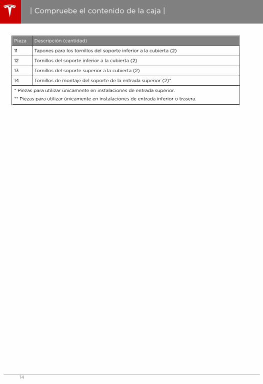
Pieza Descripción (cantidad)
11 Tapones para los tornillos del soporte inferior a la cubierta (2)
12 Tornillos del soporte inferior a la cubierta (2)
13 Tornillos del soporte superior a la cubierta (2)
14 Tornillos de montaje del soporte de la entrada superior (2)*
* Piezas para utilizar únicamente en instalaciones de entrada superior.
** Piezas para utilizar únicamente en instalaciones de entrada inferior o trasera.
| Compruebe el contenido de la caja |
14

Herramientas y materiales necesarios
Antes de instalar el conector de pared, reúna las siguientes herramientas y materiales:
• Lápiz o marcador
• Punzón (opcional, para perforar la plantilla de cartón)
• Pelacables
• Voltímetro o multímetro digital (para medir la tensión de CA en la ubicación de instalación)
• Destornillador Phillips
• Destornillador pequeño de cabeza plana
• Destornillador grande de cabeza plana (opcional, para desmontar los tapones de plástico)
• Destornillador Torx T20 de seguridad
• Destornillador Torx T10
• Pasamuros M20 y M32 (también conocidos como juntas estancas)
• Terminales (el diámetro de los terminales depende del diámetro del cableado de alimentación
y la construcción)
• Cableado (use un cable de red trenzado de dos hilos, para un máximo de 15 m entre
conectores de pared)
Nota: Tesla recomienda que use un cable blindado para limitar las posibles interferencias.
• Nivel
• Taladro
Resumen de los pasos de instalación
Aviso: Una vez que tienda los cables de servicio hasta la ubicación de instalación a través deun conducto resistente al fuego de metal, instale el disyuntor apropiado en sentido aguasarriba, DESCONECTE Y COMPRUEBE QUE NO HAY ALIMENTACIÓN ANTES DE CONTINUAR.
Después, realice estos pasos para instalar el conector de pared:
• Instale el soporte del perfil inferior para el cableado a través de la entrada trasera o inferior enla página 16
• Instalación del soporte de la entrada superior para cableado superior en la página 17• Preparación de la instalación en la página 18• Conexión del cableado en la página 19• Ajuste de la corriente de funcionamiento en la página 21• Fijación de la cubierta de sellado y encendido en la página 22
| Instrucciones de instalación paso a paso |
| Instrucciones de instalación paso a paso | 15
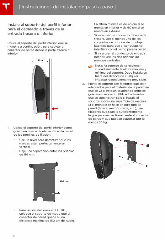
Instale el soporte del perfil inferiorpara el cableado a través de laentrada trasera o inferior
Utilice el soporte del perfil inferior, que semuestra a continuación, para cablear elconector de pared desde la parte trasera oinferior.
1. Utilice el soporte del perfil inferior comoguía para marcar la ubicación en la paredde los tornillos de fijación.
• Use un nivel para garantizar que lasmarcas están perfectamente envertical.
• Deje una separación entre los orificiosde 114 mm.
• Para las instalaciones en EE. UU.,coloque el soporte de modo que elconector de pared quede a unadistancia máxima de 150 cm del suelo.
La altura mínima es de 45 cm si semonta en interior y de 60 cm si semonta en exterior.
• Si va a usar un conducto de entradatrasero, use al menos uno de losconjuntos de orificios de montajelaterales para que el conducto nointerfiera con el perno para la pared.
• Si va a usar el conducto de entradainferior, use los dos orificios demontaje centrales.
Nota: Asegúrese de seleccionarcuidadosamente la altura máxima ymínima del soporte. Debe instalarsefuera del alcance de cualquierimpacto razonablemente previsible.
2. Monte el soporte con fijadores que seanadecuados para el material de la pared enque se va a instalar, taladrando orificiosguía si es necesario. Utilice los tornillosque se suministran sólo si instala elsoporte sobre una superficie de madera.Si el montaje se hace en otro tipo depared (hueca, mampostería, etc.), usefijadores que sean lo suficientementelargos para anclar firmemente el conectorde pared y que puedan soportar por lomenos 36 kg.
| Instrucciones de instalación paso a paso |
16

Instalación del soporte de laentrada superior para cableadosuperior
El soporte de la entrada superior permitepasar el cable de servicio al alojamiento delconector de pared desde la parte superior, taly como se muestra a continuación.
1. Utilice la plantilla de cartón y un nivelcomo guía para marcar la ubicación en lapared de los tornillos de fijación.
• Use un nivel para garantizar que lasmarcas están perfectamente envertical.
• Deje una separación entre los orificiosde 155 mm.
• Coloque el soporte de modo que elconector de pared quede a unadistancia máxima de 150 cm del suelo.La altura mínima es de 45 cm si semonta en interior y de 60 cm si semonta en exterior.
Nota: Asegúrese de seleccionarcuidadosamente la altura máxima ymínima del soporte. Debe instalarsefuera del alcance de cualquierimpacto razonablemente previsible.
2. (Opcional) Hay dos orificios de instalaciónadicionales. Para usar estos orificios,utilice un destornillador de cabeza planapara retirar el plástico que los cubre. Estosorificios están separados 70 mm.
3. Monte el soporte con fijadores que seanadecuados para el material de la pared enque se va a instalar, taladrando orificiosguía si es necesario. Utilice los tornillosque se suministran sólo si instala elsoporte sobre una superficie de madera.Si el montaje se hace en otro tipo depared (hueca, mampostería, etc.), usefijadores que sean lo suficientementelargos para anclar firmemente el conectorde pared y que puedan soportar por lomenos 36 kg.
| Instrucciones de instalación paso a paso |
| Instrucciones de instalación paso a paso | 17

Preparación de la instalación
Siga estas instrucciones para retirar la cubiertay pasar el cable de servicio por el conector depared.
1. Use un destornillador Torx T10 para retirarel tornillo de la parte inferior de lacubierta exterior. Retire con cuidado lasgrapas de los lados y de la parte superior.Utilice para ello un destornillador decabeza plana y retire la cubierta porcompleto. Guarde el tornillo y la cubiertapara el reensamblaje.
2. Use un destornillador Torx T20 deseguridad para retirar los seis tornillos dela cubierta de sellado. Retire con cuidadola cubierta de sellado y desconecte elcable plano. Guarde los tornillos y lacubierta para el reensamblaje.
Precaución: No deje la cubierta desellado colgando del cable plano. Silo hace, se puede dañar el cableplano o los conectores.
3. Para la configuración de entrada superior,instale el cable en el bloque de terminalesdel soporte de la entrada superior, tal ycomo se muestra en Conexión delcableado en la página 19. Acontinuación, vuelva a esta sección paracontinuar con el paso siguiente. Para laconfiguración de entrada trasera o inferior,proceda con el paso siguiente.
4. Coloque el conector de pared en elsoporte y asegúrese de que las cuatrolengüetas de montaje están alineadascorrectamente.
5. Utilice un destornillador Torx T20 parainstalar los dos tornillos de montajesuperiores de la cubierta. Coloque lostapones cosméticos de los tornillos.
6. Utilice un destornillador Torx T20 parainstalar los dos tornillos de montajeinferiores de la cubierta. Coloque lostapones cosméticos de los tornillos en susitio.
| Instrucciones de instalación paso a paso |
18

Conexión del cableado
Nota: Consulte con un electricista o lasnormativas locales para determinar eltamaño del cable adecuado para lascorrientes de su conector de pared.
Nota: Es responsabilidad del instaladoridentificar si se necesita una masaadicional para garantizar el cumplimientode la normativa local. La masa debe estarinstalada en la fuente de alimentación yno en la entrada del cable hacia elconector de pared.
Aviso: No conecte los cables de serviciohasta que haya leído y comprendidocompletamente los conceptos descritosen Cableado de servicio en la página 7. Sino está seguro del tipo de corrientedisponible en el panel de servicio,consulte a un electricista o póngase encontacto con Tesla para obtener ayuda.
1. Desconecte la alimentación.
Aviso: RIESGO DE DESCARGAELÉCTRICA! Antes de continuar, useun voltímetro para comprobar que laalimentación está desconectadaconfirmando que NO HAY TENSIÓNen los cables o terminales bajoservicio.
2. En una instalación con entrada superior,pase el cable de servicio a través delsoporte de la entrada superior o delconector de pared. Use un pasamuros M32para sellar la abertura del conducto ocable de alimentación. Para elfuncionamiento a 80 A, use un cable decobre de tipo 2AWG de 90 °C o siga lasnormativas locales.
Nota: El significado de los colorespuede variar en función del país. Sigatoda la normativa nacional y localaplicable respecto a los códigos decolores del cableado.
La siguiente ilustración muestra unejemplo del cableado para el soporte de laentrada superior.
La siguiente ilustración muestra unejemplo del cableado para el soporte delperfil inferior.
3. Pele los cables de servicio que van albloque de terminales en el soporte de laentrada superior una longitud de 18 mm.Se recomienda usar terminales.
Nota: En una instalación con entradasuperior, los cables flexiblespreinstalados que van del soporte dela entrada superior a la cubierta yatienen terminales y no es necesariopelarlos.
| Instrucciones de instalación paso a paso |
| Instrucciones de instalación paso a paso | 19
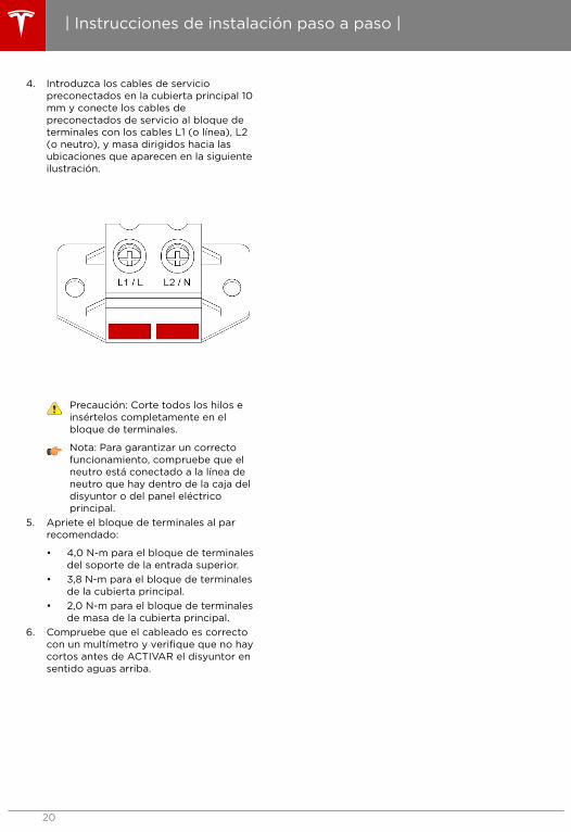
4. Introduzca los cables de serviciopreconectados en la cubierta principal 10mm y conecte los cables depreconectados de servicio al bloque determinales con los cables L1 (o línea), L2(o neutro), y masa dirigidos hacia lasubicaciones que aparecen en la siguienteilustración.
Precaución: Corte todos los hilos einsértelos completamente en elbloque de terminales.
Nota: Para garantizar un correctofuncionamiento, compruebe que elneutro está conectado a la línea deneutro que hay dentro de la caja deldisyuntor o del panel eléctricoprincipal.
5. Apriete el bloque de terminales al parrecomendado:
• 4,0 N-m para el bloque de terminalesdel soporte de la entrada superior.
• 3,8 N-m para el bloque de terminalesde la cubierta principal.
• 2,0 N-m para el bloque de terminalesde masa de la cubierta principal.
6. Compruebe que el cableado es correctocon un multímetro y verifique que no haycortos antes de ACTIVAR el disyuntor ensentido aguas arriba.
| Instrucciones de instalación paso a paso |
20

Ajuste de la corriente defuncionamiento
Siga estas instrucciones para configurar elinterruptor DIP. La siguiente ilustraciónmuestra una vista ampliada de losinterruptores DIP y giratorios.
Aviso: La alimentación DEBE estarDESCONECTADA antes de ajustar ocambiar los interruptores DIP o giratorios.El sistema no reconocerá el cambio deestos interruptores con la alimentaciónCONECTADA y será peligroso debido a laposibilidad de descargas eléctricas.
1. DESCONECTE la alimentación.2. Use un objeto no conductivo (como un
bolígrafo de plástico) para ajustar elinterruptor DIP:
• Posición 1 del interruptor:
• Para realizar una conexión delínea a línea (240 V), ajuste elinterruptor DIP hacia ABAJO.
• En una conexión de línea a neutro(277 V), ajuste el interruptor DIPhacia ARRIBA (posición ON).
Aviso: Antes de ajustar losinterruptores DIP, verifique el tipode servicio de entrada queproporciona la empresa desuministro.
• Posición 2 del interruptor:
• La posición 2 del interruptor DIPdebe estar siempre en la posiciónhacia ARRIBA.
InterruptorDIP
Hacia arriba(ON)
Hacia abajo
Posición 1 Línea aneutro (277V)
Línea alínea (240V)
Posición 2 Normal Noaplicable
3. Ajuste el interruptor giratorio según elajuste apropiado de corriente compatiblecon su disyuntor. Las capacidades de losdisyuntores típicos son: 15 A, 20 A, 25 A,30 A, 35 A, 40 A, 45 A, 50 A, 60 A, 70 A,80 A, 90 A y 100 A.
Use un destornillador pequeño de cabezaplana para ajustar el interruptor giratoriode acuerdo con el ajuste correcto deldisyuntor. Los ajustes correspondientesdel interruptor giratorio para losdisyuntores típicos aparecen en la tablasiguiente:
Posicióndelinterruptorgiratorio
Corrientemáxima desalida
Disyuntor
0 Modo deprueba
N/D
1 12 A 15 A
2 16 A 20 A
3 20 A 25 A
4 24 A 30 A
5 28 A 35 A
6 32 A 40 A
7 36 A 45 A
8 40 A 50 A
9 48 A 60 A
A 56 A 70 A
B 64 A 80 A
C 72 A 90 A
D 80 A 100 A
E No es unaselecciónválida
N/D
F Modoesclavo
N/D
4. Vuelva a conectar el cable plano a lacubierta de sellado.
5. Vuelva a instalar la cubierta de sellado.Use un destornillador Torx T20 deseguridad para fijar ligeramente la
| Instrucciones de instalación paso a paso |
| Instrucciones de instalación paso a paso | 21

cubierta de sellado instalando solo eltornillo superior.
6. CONECTE la alimentación.7. Si la instalación es correcta, los LED
parpadearán brevemente de formasecuencial en verde con un patrón quefinaliza con el LED verde superioriluminado permanentemente. Si hay unLED rojo parpadeando o iluminadopermanentemente, consulte Resolución deproblemas en la página 23 y solucione elerror antes de continuar.
Nota: Para revisar el patrón de lasluces parpadeantes, mantengapresionado el botón RESET durante 5segundos.
8. DESCONECTE la alimentación.9. Escriba la información de contacto del
instalador en la etiqueta del interior delconector de pared.
Fijación de la cubierta de sellado yencendido
1. Use un destornillador Torx T20 deseguridad para instalar los tornillosrestantes en la cubierta de sellado.Asegúrese de que la cubierta estácorrectamente alineada antes de apretarcompletamente los tornillos.
2. Coloque la cubierta exterior sobre lacubierta de sellado comenzando por lalengüeta de la parte superior. Acople lasfijaciones de los laterales y alinee lalengüeta de montaje con la cubierta en laparte inferior.
3. Use un destornillador Torx T10 parainstalar el tornillo que fija la parte inferiorde la cubierta exterior a la cubierta.
4. Cierre las aberturas sin usar con taponespara los conductos de señal yalimentación.
Nota: No deben quedar aberturasvisibles hacia el interior del conectorde pared, y el conector debe estarcompletamente sellado del exterior.
5. CONECTE la alimentación. La instalaciónes correcta si los LED pasan por unasecuencia de parpadeo que finaliza conlos LED verdes superiores ENCENDIDOScontinuamente. Si hay un LED rojoparpadeando o iluminadopermanentemente, solucione el errorantes de continuar (consulte Resoluciónde problemas en la página 23).
Nota: Para revisar el patrón de lucesparpadeantes, mantenga presionadoel botón Reset durante 5 segundos.
6. Intente cargar el vehículo para asegurarsede que el conector de pared funcionacorrectamente y de que carga a lacorriente de funcionamiento seleccionada.Para obtener instrucciones sobre cómorealizar la carga, consulte la informaciónde usuario suministrada junto con elvehículo.
| Instrucciones de instalación paso a paso |
22

Lucesverdes
Luzamarilla
Luz roja Volver aintentarautomáticamente
Significado Qué hacer
Luzsuperiorencendida
Apagado Apagado No aplicable Alimentaciónencendida. Elconector de paredestá encendido y enespera, pero no estácargando elvehículo.
No aplicable.
Lucessecuenciales
Apagado Apagado No aplicable El conector depared estácargando elvehículo.
No aplicable.
Lucessecuenciales
1parpadeo
Apagado No aplicable La corriente decarga es reducidadebido a la altatemperaturadetectada en elconector delvehículo.
Asegúrese de que elconector del vehículo(manija de carga) estáinsertadocompletamente en laentrada de carga delvehículo, que no estácubierto por nada yque no tiene cercaninguna fuente decalor. Si el problemacontinúa con unatemperatura ambientenormal (por debajo de38 °C), póngase encontacto con Tesla.
| Resolución de problemas |
| Resolución de problemas | 23

Lucesverdes
Luzamarilla
Luz roja Volver aintentarautomáticamente
Significado Qué hacer
Lucessecuenciales
2 parpadeos
Apagado No aplicable La corriente decarga es reducidadebido a la altatemperaturadetectada en elenchufe de pared oen los terminales deentrada delconector de pared.
Si se utiliza unenchufe de pared,asegúrese de que estácompletamenteinsertado en elreceptáculo, que noestá cubierto pornada y que no estácerca de ningunafuente de calor. Si elconector de paredestá conectadodirectamente alenchufe de pared,asegúrese de que elconector de pared noestá cubierto pornada y que no estácerca de ningunafuente de calor. Si elproblema continúacon una temperaturaambiente normal (pordebajo de 38 °C),póngase en contactocon Tesla.
Lucessecuenciales
3 parpadeos
Apagado No aplicable Corriente de cargareducida debido ala alta temperaturadetectada en elconector de pared.
Asegúrese de que elconector de pared noestá cubierto pornada y que no estácerca de ningunafuente de calor. Si elproblema continúacon una temperaturaambiente normal (pordebajo de 38 °C),póngase en contactocon Tesla.
| Resolución de problemas |
24

Lucesverdes
Luzamarilla
Luz roja Volver aintentarautomáticamente
Significado Qué hacer
Apagado Apagado 1parpadeo
Después de15 minutos yhasta 4veces
Fallo de masa. Hayuna fuga decorriente eléctricapor un lugarpeligroso. Posiblefallo de línea a masao de neutro a masa.
Desconecte la manijadel vehículo. Vuelva aconectar e intente denuevo. Si el problemacontinúa,DESCONECTE eldisyuntor quealimenta el conectorde pared y espere 10segundos. CONECTEel disyuntor y vuelva aintentarlo. Si elproblema persiste,póngase en contactocon Tesla.
Apagado Apagado 2 parpadeos
Después de1 minuto yhasta 4veces
No se ha detectadouna conexión demasa en el conectorde pared.
Asegúrese de que elconector de paredestá correctamenteconectado a tierra. Encaso de duda,consulte a unelectricista sobrecómo realizar unacorrecta conexión amasa en el disyuntor ocaja de distribuciónde energía paraconectarcorrectamente elconector de pared.
Apagado Apagado 3 parpadeos
No Error de cableadoen la entrada: esposible que se hayaintercambiado laconexión de línea yneutro.
El cableado deentrada entre elenchufe de pared y elconector de pared seha instaladoincorrectamente.Consulte a suelectricista.
Apagado Apagado 4 parpadeos
Después de1 minuto yhasta 4veces
Protección de sobreo bajatensión.
Consulte a suelectricista paraconocer la tensiónapropiada para eldisyuntor quealimenta el conectorde pared.
| Resolución de problemas |
| Resolución de problemas | 25

Lucesverdes
Luzamarilla
Luz roja Volver aintentarautomáticamente
Significado Qué hacer
Apagado Apagado 5 parpadeos
Nuevointento tras 1minuto (sinlímite denuevosintentos)
Protección desobretensión.
Desactive el ajuste decorriente de carga enel vehículo. Si elproblema persiste y elvehículo conectado esfabricado por Tesla,póngase en contactocon Tesla.
Si el problemapersiste y el vehículoconectado no esfabricado por Tesla,póngase en contactocon el fabricante delvehículo.
Apagado Apagado 6 parpadeos
Nuevointento tras 1minuto (sinlímite denuevosintentos)
Fallo del piloto: Elnivel del piloto esincorrecto
Enchufe el vehículo aotro conector depared si es posible oenchúfelo al conectormóvil suministradocon el vehículo; si elproblema persiste,póngase en contactocon Tesla.
Luzsuperiorencendida
Apagado 1parpadeo
No Protección deexceso detemperatura(desconexión)
Asegúrese de que elconector de pared, losconectores delvehículo y el enchufede pared (sicorresponde) no estáncubiertos por nada yque no tienen cercaninguna fuente decalor. Si el problemacontinúa con unatemperatura ambientenormal (por debajo de38 °C), póngase encontacto con Tesla.
Luzsuperiorencendida
Apagado 2 parpadeos
No Vehículo distinto aTesla intentandorealizar unaconexión a una redeléctrica nocompatible.
Las redes eléctricascompatibles son:monofásica o trifásicade 400 V.
Luzsuperiorencendida
Apagado 3 parpadeos
No Ajuste incorrectodel interruptorgiratorio.
Consulte a suelectricista.
| Resolución de problemas |
26

Lucesverdes
Luzamarilla
Luz roja Volver aintentarautomáticamente
Significado Qué hacer
Luzsuperiorencendida
Apagado 4 parpadeos
No aplicable El disyuntorcomparte la red:Hay más de unconector de pareddefinido comomaestro.
Defina uno de losconectores de paredcomo esclavo.
Luzsuperiorencendida
Apagado 5 parpadeos
No aplicable El disyuntorcomparte la red:Hay más de tresconectores depared definidoscomo maestro.
Pase uno o variosconectores de pared aun circuito diferente ydesconéctelo de estared de comparticiónde disyuntor.
Luzsuperiorencendida
Apagado 6 parpadeos
No aplicable El disyuntorcomparte la red:Los conectores depared en red tienendiferentescapacidadesmáximas decorriente.
Póngase en contactocon Tesla.
Apagado Apagado Rojopermanente
No Fallo de hardwaredel conector depared. Los fallosposibles incluyenlos siguientes:
• Error delcontactor
• Error decomprobaciónautomática enlos circuitosCCID
• Otros posiblesfallos dehardwarepuedenlocalizarse en elMCU, la salida3V3 o el sensortérmico.
Póngase en contactocon Tesla.
Restablecimiento
Si un fallo provoca que se ilumine o parpadee una luz ROJA de error y la condición de fallo secorrige, puede usar el botón RESET para restablecer el conector de pared y hacer que vuelva afuncionar correctamente.
| Resolución de problemas |
| Resolución de problemas | 27

1. Presione el botón RESET de dos a tres segundos. Si la luz superior cambia de ROJA a VERDE,suelte el botón RESET. En este método de restablecimiento, el mensaje de fallo se borra perono se fuerza el reinicio del conector de pared.
2. En una situación rara, es posible que necesite forzar el reinicio del conector de pared sin tenerque volver a hacer el ciclo de la alimentación. Presione el botón RESET durante cincosegundos. Si la luz superior cambia de ROJA a VERDE, suelte el botón RESET. La luz superiordebería permanecer iluminada en VERDE. Si la luz vuelve a parpadear en ROJO, no se hacorregido el estado de fallo.
| Resolución de problemas |
28

¿Tiene alguna pregunta?
• Estados Unidos y Canadá:
• [email protected]• +1-650-681-6133
• México
• [email protected]• +1-877-798-3752
| Resolución de problemas |
| Resolución de problemas | 29

1. DESCONECTE la alimentación.
Aviso: RIESGO DE DESCARGAELÉCTRICA! Antes de continuar, useun voltímetro para comprobar que laalimentación está desconectadaconfirmando que NO HAY TENSIÓNen los cables o terminales bajoservicio.
2. Use un objeto no conductivo (como unbolígrafo de plástico) para ajustar losinterruptores DIP de acuerdo con el ajustede la red eléctrica y el uso compartido deldisyuntor (consulte Ajuste de la corrientede funcionamiento en la página 21).
3. Use un destornillador pequeño de cabezaplana para ajustar el interruptor giratorioen la posición "0" y hacer que el conectorde pared entre en el modo de prueba.
Aviso: La alimentación DEBE estarDESCONECTADA antes de ajustar ocambiar los interruptores DIP ogiratorios. El sistema no reconocerá elcambio de estos interruptores con laalimentación CONECTADA y serápeligroso debido a la posibilidad dedescargas eléctricas.
4. Vuelva a conectar el cable plano a lacubierta de sellado.
5. Use un destornillador Torx T20 deseguridad para fijar ligeramente lacubierta de sellado instalando solo eltornillo superior.
6. CONECTE el disyuntor.7. Compruebe si se ENCIENDE algún LED
rojo después de una secuencia de LED; sies así, hay un fallo en la instalación.
8. Escuche si el contactor o relé emite un clicde apertura o cierre.
9. Compruebe si hay una secuencia de LEDverdes (durante 5 segundos).
Los LED volverán a iluminarse con el LEDsuperior verde ENCENDIDO y los LEDrojos parpadeando (3 veces).
Nota: Para revisar el patrón de lucesparpadeantes, mantenga presionadoel botón Reset durante 5 segundos.
10. DESCONECTE el disyuntor.11. Extraiga el tornillo de la cubierta de
sellado y la cubierta de sellado.Desconecte el cable plano.
Precaución: No deje la cubierta desellado colgando del cable plano. Silo hace, se puede dañar el cableplano o los conectores.
12. Vuelva a colocar el interruptor giratorio enel ajuste apropiado (consulte Ajuste de lacorriente de funcionamiento en la página21).
13. Vuelva a conectar el cable plano a lacubierta de sellado.
14. Vuelva a montar todos los tornillos einstale la cubierta exterior (consulte Fijación de la cubierta de sellado yencendido en la página 22).
| Apéndice A: Comprobación del funcionamiento correcto |
30

El conector de pared cuenta con unacaracterística que permite establecercomunicación entre distintos conectores depared para dividir la carga máxima disponibleentre un máximo de 4 conectores de pared. Elcable que se usa en esta red local debecompartir el conducto de alimentaciónprincipal o estar dentro de un conductoindependiente.
Puede conectar los conectores de pared enserie con secuencia, en una configuración decadena.
Nota: Considere tomar precaucionesadicionales para evitar que se introduzcaagua en los conectores de pared alinstalarlos en el exterior.
Nota: Consulte con un electricista paragarantizar que la instalación cumple lasnormativas locales.
Conexión en serie con secuencia dediferentes conectores de pared
Cada conector de pared tiene un bloque determinales dedicado al cableado decomunicación, como se muestra acontinuación. El terminal de la izquierda delbloque es el terminal de entrada y el de laderecha el de salida.
1. Forme una red conectada en margaritaconectando los cables de OUT a IN y
siempre de positivo a positivo y denegativo a negativo entre los diferentesconectores de pared del conjunto(consulte Ejemplo del cableado decomunicación en la página 32).
• Los cables de señal entre todos losconectores de pared deben pasar porun conducto de señal. Use unpasamuros con homologación UL M20para sellar la abertura del conducto deseñal.
• Si el cable de señal se conduce dentrodel conducto que contiene los cablesde alimentación, la clasificación deaislamiento del cable de señal debeser igual o mayor que la de los cablesde alimentación.
• La distancia máxima entre losconectores de pared es de 15 m.
• Use un cable trenzado de dos hilospara el cable de señal.
Nota: Tesla recomienda que use uncable apantallado para limitar lasposibles interferencias.
2. Defina un conector de pared comomaestro ajustando el interruptor giratorioen la posición 1 a 8, en función de lamáxima corriente de salida disponible.Defina hasta 3 conectores de pared comoesclavos situando el interruptor giratorioen la posición F. En la red de comparticiónde carga, solo se puede asignar unaunidad como maestro (consulte Ajuste dela corriente de funcionamiento en lapágina 21).
3. Confirme que la red con carga compartidaestá correctamente instalada mediante laobservación de los indicadores LED delconector de pared. Cuando accione eldisyuntor por primera vez, las luces verdesse ENCENDERÁN 5 segundos para indicarque la instalación es correcta, como sigue:
Lucesverdes
Luzamarilla
Luzroja
Significado
Encendida(superior einferior)
Apagado
Apagado
Unidadmaestra
Encendida(inferior)
Apagado
Apagado
Unidadesclava
| Apéndice B: Conexión opcional para compartir carga |
| Apéndice B: Conexión opcional paracompartir carga |
31
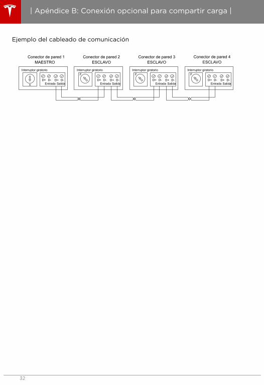
Ejemplo del cableado de comunicación
Conector de pared 1MAESTRO
Conector de pared 2ESCLAVO
Conector de pared 3ESCLAVO
Conector de pared 4ESCLAVO
8
Interruptor giratorio
D+ D- D+ D-Entrada Salida
FInterruptor giratorio
D+ D- D+ D-Entrada Salida
FInterruptor giratorio
D+ D- D+ D-Entrada Salida
FInterruptor giratorio
D+ D- D+ D-Entrada Salida
| Apéndice B: Conexión opcional para compartir carga |
32

Términos generales
Sujeta a las exclusiones y limitacionesdescritas a continuación, la Garantía limitadadel equipo de carga cubre el reembolso, lasreparaciones o sustituciones necesarias paracorregir cualquier defecto de fabricación en elconector de pared, el conector móvil o eladaptador de carga Tesla suministrado defábrica que se produzca por el uso normaldurante un período de 12 meses desde lafecha de facturación al cliente. Cualquierconector o adaptador Tesla incluido por Teslaen la compra y provisión inicial de un vehículoTesla está cubierto por la sección de Garantíabásica limitada del vehículo de la Nuevagarantía limitada del vehículo por cuatro (4)años o 80 000 km, , lo que se produzcaprimero, sujeto a los términos y condicionesde la Nueva garantía limitada.
Esta Garantía limitada del equipo de carga nocubre ningún daño o avería directo o indirectocausado por, debido a o como resultado deldesgaste o deterioro normal, abuso, usoindebido, negligencia, accidente, uso omantenimiento inapropiados, falta de uso omantenimiento, almacenamiento o transporte,incluyendo, sin carácter limitativo, cualquierade las siguientes situaciones:
• No seguir las instrucciones, lasadvertencias y el mantenimiento descritoen la documentación suministrada juntocon el conector o adaptador Tesla;
• Factores externos, incluyendo, sin carácterlimitativo, los objetos que impacten contracualquier conector o adaptador Tesla,cableado eléctrico, cajas de derivación,disyuntores, clavijas o tomas de corrientedefectuosos o dañados, el medioambiente o hechos de fuerza mayor,incluyendo, no taxativamente, losincendios, los terremotos, el agua, losrayos y otras condicionesmedioambientales.
• Aspecto general o daños a la pintura,incluidos arañazos, roturas, abolladuras ygrietas.
• No ponerse en contacto con Tesla trasdescubrir un defecto cubierto por estaGarantía limitada del equipamiento decarga.
• Cualquier reparación, alteración omodificación al conector o adaptadorTesla o una de sus piezas, o la instalacióno uso de piezas o accesorios realizadaspor una persona o centro no autorizadoso certificados para ello;
• Reparación o mantenimiento inadecuadoso falta de los mismos, incluido el uso depiezas o accesorios no originales de Tesla.
• Uso para fines comerciales.
| Garantía limitada de equipamiento de carga |
| Garantía limitada de equipamiento decarga |
33

Aunque Tesla no le obliga a realizar todas lastareas de reparación, servicio omantenimiento en un Centro de servicio deTesla o taller autorizado de Tesla, estaGarantía limitada del equipamiento de cargapodría quedar anulada o su cobertura podríaexcluirse a causa de una reparación, servicio omantenimiento inadecuados o una falta de losmismos. Los Centros de servicio de Tesla y lostalleres autorizados de Tesla disponen de laformación, la experiencia, las herramientas ylos suministros necesarios para los conectoresy adaptadores Tesla y, en ciertos casos,pueden emplear s las únicas personascapacitadas o ser los únicos establecimientosautorizados o certificados para trabajar conestos conectores y adaptadores Tesla. Teslarecomienda encarecidamente que haga todoslos trabajos de mantenimiento, servicio yreparación en un Centro de servicio Tesla otaller autorizado de Tesla para evitar laanulación, o excluir la cobertura de esteequipamiento de carga, de esta Garantíalimitada.
Límites de responsabilidad
Esta Garantía limitada del Equipo de carga esla única garantía explícita relacionada con suconector o adaptador Tesla. Las condiciones ygarantías implícitas o explícitas que surjanbajo las leyes locales aplicables, normativasfederales u otras legislaciones, en ley oequidad, si es aplicable, incluyendo, sincarácter limitativo, las condiciones y garantíasimplícitas de comercialización, calidadcomercial, idoneidad para un fin específico,durabilidad o aquello que pueda surgir poracuerdo o uso comercial, quedan excluidas enla medida en que lo permitan las leyes localeso limitadas en su duración al periodo devigencia de esta Garantía limitada del Equipode carga. En la máxima medida en que lopermitan las leyes locales, la ejecución de lasreparaciones y sustituciones necesarias de laspiezas nuevas o refabricadas de Tesla para losdefectos cubiertos es la solución exclusiva quecontempla esta Garantía limitada del Equipode carga o cualquier garantía implícita. En lamedida en que lo permitan las leyes locales, laresponsabilidad estará limitada al preciorazonable para la sustitución o reparación delconector o el adaptador Tesla aplicable, y nodebe superar el precio de venta sugerido porel fabricante. La sustitución puede efectuarsepor piezas del mismo tipo y calidad, incluidaspiezas refabricadas, reacondicionadas o nooriginales del fabricante, según sea necesario.
Tesla no tiene ninguna responsabilidad porcualquier defecto bajo esta Garantía limitadadel Equipo de carga excederá el valor demercado razonable del conector o eladaptador Tesla correspondiente en elmomento inmediatamente precedente aldescubrimiento del defecto. Asimismo, lasuma de todos los beneficios pagaderos bajoesta Garantía limitada del Equipo de carga nosuperará el precio que se ha pagado por elconector o adaptador Tesla respectivo.
Tesla no autoriza a ninguna persona o entidada crear cualquier otra obligación oresponsabilidad relacionada con esta Garantíalimitada del equipamiento de carga. Ladecisión de reparar o sustituir una pieza o deutilizar una pieza nueva, reacondicionada orefabricada será tomada por Tesla a su enteradiscreción.
| Garantía limitada de equipamiento de carga |
34

En la máxima medida en que lo permita lalegislación local, Tesla no se hace responsablepor la presente de ningún daño indirecto,fortuito, especial ni derivado que surja de oesté relacionado con el conector o adaptadorTesla, incluyendo, sin carácter limitativo, eltransporte hacia y desde un Centro de servicioautorizado de Tesla, la pérdida de valor delvehículo, del conector o del adaptador Tesla,la pérdida de tiempo, la pérdida de ingresos, lapérdida de uso, la pérdida de bienespersonales o materiales, las molestias oinconvenientes, los daños o sufrimientosemocionales, las pérdidas comerciales(incluyendo, sin carácter limitativo, laspérdidas de beneficios o ingresos), los costesde remolcado, los pasajes de autobús, elalquiler de vehículos, los importes de lasllamadas a revisión, los gastos de gasolina, loscostes de alojamiento, los daños al vehículo deremolque y los gastos adicionales, comollamadas de teléfono, envío de fax y tasas decorreo.
Las exclusiones y limitaciones anteriores seaplicarán tanto si su reclamación se presentaen virtud de contratos, responsabilidadesextracontractuales (incluyendo negligencia ynegligencia grave), incumplimiento decondición o garantía, o tergiversación (ya seanegligente o de otra clase) como si se hace dealguna otra manera con arreglo a la ley o porequidad, aunque Tesla haya recibidonotificación de la posibilidad de dichos dañoso que estos sean razonablemente previsibles.
Nada en esta Garantía limitada del Equipo decarga excluirá (o, en cualquier forma, limitará)la responsabilidad de Tesla por las lesionespersonales o mortales causadas única yexclusivamente por la negligencia de Tesla o lade sus empleados, agentes o subcontratistas(según proceda), el fraude o tergiversaciónfraudulenta o cualquier otra responsabilidaden la medida en que esta sea demostrada enuna sentencia firme por un juzgado con lajurisdicción competente, y no pueda excluirseo limitarse como una cuestión de derecholocal.
Leyes de aplicación de la garantía yresolución de litigios
En la mayor medida en que lo permitan lalegislación local, Tesla requiere que envíeprimero una notificación por escrito sobrecualquier fallo de fabricación en un margen detiempo razonable, y dentro del período degarantía aplicable especificado en estaGarantía limitada del Equipo de carga,indicando cualquier defecto de fabricación, ydeberá conceder un tiempo razonable paraque Tesla tenga la oportunidad de efectuar lasreparaciones necesarias antes de dirigirse anuestro programa de resolución de conflictos(que se describe a continuación). Envíe sunotificación por escrito sobre la resolución dela disputa a la siguiente dirección:
Estados Unidos:Tesla Motors, Inc.3500 Deer Creek RoadPalo Alto, California 94304Teléfono: 1-877-798-3752
Canadá:Tesla Motors Canada ULC1325 Lawrence Avenue EastToronto, ON M3A 1C6Teléfono: 1-877-798-3752
Incluya la siguiente información:
• Factura de conector o adaptador Teslafecha;
• Su nombre y datos de contacto.• Nombre y ubicación del proveedor de
Tesla y/o del Centro de servicio de Teslamás cercano;
• Descripción del defecto.• Número de veces que ha intentado
resolver el problema con Tesla, o dereparaciones o servicios no efectuadospor Tesla.
| Garantía limitada de equipamiento de carga |
| Garantía limitada de equipamiento decarga |
35

En caso de que surja algún litigio, diferencia ocontroversia entre usted y Tesla en relacióncon esta Garantía limitada del equipamientode carga, Tesla estudiará todas lasposibilidades para alcanzar un acuerdoamistoso. En caso de que no se alcance unacuerdo, Tesla ofrece un programa deresolución de conflictos mediante el:
NATIONAL CENTER FOR DISPUTESETTLEMENT (“NCDS”)P.O. Box 526Mt. Clemens, MI 480461-866-629-3204
Tesla requiere que usted presente su peticióna nuestro programa de resolución deconflictos mediante arbitraje y espere unaresolución antes de recurrir según las leyesfederales o del estado (que incluyen 15 U.S.C.Sección 2310 o del Código Civil de California1793,22(b)), aunque usted puede tenerderecho a recurso sin arbitraje según ciertasleyes del estado o si se aplican derechos orecursos no creados por estas leyes. Esteprograma de resolución de conflictosgestionado por NCDS es sin cargo para ustedy se realiza por los profesionales locales deNCDS que tienen formación y experiencia enmediación y arbitraje.
NCDS resuelve los conflictos relacionados conla Garantía limitada del Equipo de carga quesurjan durante el período de garantíaespecificado en esta Garantía limitada delEquipo de carga. Usted debe presentar unasolicitud de arbitraje a NCDS dentro de los 60días (o 6 meses en ciertas jurisdicciones)posteriores a la caducidad delcorrespondiente período de garantía, siempreque usted haya enviado notificación porescrito a Tesla del supuesto defecto durante elcorrespondiente período de garantía.
Para empezar el arbitraje, debe ponerse encontacto con NCDS en el número1-866-629-3204 o P.O. Box 526, Mt. Clemens,MI 48046, completar un formulario dereclamación de NCDS y enviarlo a NCDS.Suministre también una copia de sunotificación escrita enviada a Tesla y/o toda lainformación requerida en esa notificaciónindicada arriba, la resolución deseada, y todoslos recibos si solicita un reembolso. Al recibirsu solicitud, NCDS se pondrá en contacto conusted con respecto al caso y le proveerá másinformación sobre el programa.
Cuando NCDS reciba la solicitud, la enviará aTesla para su respuesta. Después de analizartoda la información relativa a su caso, NCDSplanificará una evaluación técnica sicorresponde. Si el cliente lo solicita, seefectuará una audiencia oral antes de llegarsea una resolución. En esta audiencia, seadmiten todos los medios de prueba. Despuésde considerar todos los testimonios ydocumentos, el árbitro analizará la legislacióncorrespondiente y emitirá una resolución. Esposible negociar un arreglo satisfactorio paratodas las partes en cualquier momento,también antes o después de la resolución delárbitro.
La decisión de NCDS es vinculante para Teslapero no para el cliente. Si el cliente acepta laresolución de NCDS, Tesla cumplirá con ella enun plazo razonable que no excederá los 30días después de que Tesla reciba notificaciónde su aceptación. La subsanación puedeincluir, no taxativamente, reparación;reembolso para reparaciones y gastosvinculados, como costes de transporte; yrecompra o reemplazo del conector o eladaptador Tesla. Las resoluciones de NCDS noincluyen gastos legales, ni indemnizacionespor daños y perjuicios punitivos, múltiples oemergentes, excepto daños incidentales oconcomitantes según lo requiera la legislaciónvigente. Las investigaciones y resoluciones deNCDS son admisibles como prueba encualquier procedimiento legal concerniente alconector móvil o el adaptador Tesla.
La descripción expuesta es solamente unbreve resumen del programa de resolución deconflictos gestionado por NCDS. El programade resolución de conflictos puede sermodificado en cualquier momento sinadvertencia previa. Póngase en contacto conNCDS en la dirección o teléfono citados másarriba para obtener información másactualizada concerniente al programa deresolución de conflictos.
| Garantía limitada de equipamiento de carga |
36

Aadvertencias 3ajuste de la corriente de funcionamiento 21
Bbalanceo de carga
acerca de 6balanceo de cargas
configuración de los interruptores DIP ygiratorios 21
bloques de terminalesconexión del cableado de servicio al 19recomendaciones de par 19
botón reset 6, 27, 30
Ccableado de servicio 7, 19cableado para carga compartida 31capacidades de circuitos, opcionales 6características
capacidades de circuitos, opcionales 6carga compartida 6recuperación de un corte en la redeléctrica 6recuperación y supervisión automática 6
carga compartidaejemplo del cableado de comunicación32
comprobación de funcionamiento correcto 30comprobación del contenido de la caja 13conducto, acerca de 11conectores de pared
comprobación del contenido de la caja 13conexión de los bloques de terminales 31conexión en margarita 31configuración opcional 31ejemplo del cableado de comunicación32encendido 22resolución de problemas 31restablecimiento 27, 30ubicación de 10
conexión del cableado 19copyrights 2corte en la red eléctrica, recuperación de un 6cubierta
exterior, retirada de la 18fijación de la 22retirada del sellado 18
Ddimensiones 5disyuntor del circuito
ajustes correspondientes de losinterruptores giratorios 21requisitos 10
Eencendido 22entrada superior
cableado, instalación del soporte deentrada superior para 17configuraciones, dimensión y distancia 11ejemplo del cableado de servicio 19soporte, instalación del 17
entrada trasera o inferiorconfiguraciones, dimensiones ydistancias 11ejemplo del cableado de servicio 19instalación del soporte de perfil bajo para16
errores de documentación, envío decomentarios 2especificaciones
dimensiones 5límites de temperatura 5valores de potencia 5
Ffijación de la cubierta exterior 22
Iinstalación
herramientas y materiales necesarios 15información, acerca de 2para cableado superior 17para el cableado a través de la entradatrasera o inferior 16planificación de la 7preparación de la 18recomendaciones de par 19
instalación, comprobación 30instrucciones de seguridad 3, 4interruptores DIP, configuración 21interruptores giratorios, configuración 21
| Índice |
| Índice | 37

Llímites de temperatura 5luces, diagnóstico 6luces, LED 23
Mmarcas comerciales 2
Nnormativas de comunicaciones 2notas 4
Pplanificación de la instalación
cableado de servicio 7requisitos del disyuntor 10requisitos mínimos 7tipos de instalaciones 11ubicación de los conectores de pared 10
plantilla de cartón, uso de la 16precauciones 3
Rrecuperación y supervisión automática 6requisitos mínimos 7resolución de problemas 23, 27, 29, 31resumen de la instalación 15retirada de la cubierta exterior 18
Ssoporte de perfil bajo
instalación de la 16
TTesla, información de contacto de 29
Vvalores de potencia 5
| Índice |
38 | |

-t t
rF

-t t
rF

ウォールコネクター (80A 単相) 設置マニュアル重要文書
日本国内向け仕様


このマニュアルについて.................. 2コミュニケーション規定...............................................2誤りまたは不正確な記述...............................................2著作権および商標........................................................... 2
安全ガイド...........................................3重要な安全指示............................................................... 3警告....................................................................................3注意事項........................................................................... 3注記................................................................................... 4
仕様....................................................... 5
機能.......................................................6遮断器規格オプション...................................................6自己監視と復旧...............................................................6停電................................................................................... 6ロードシェアリング.......................................................6
設置作業の計画...................................7最低必要条件................................................................... 7配線....................................................................................7アース接続....................................................................... 7200V 単相....................................................................... 7208V 3 相 Y 結線.......................................................... 7240V 3 相 デルタ結線.................................................. 8277V 3 相 Y 結線...........................................................8サーキットブレーカーの選定.......................................9ウォールコネクターの最適な設置場所...................... 9設置作業における考慮事項......................................... 10
内容物の確認..................................... 12
設置手順............................................. 14必要な工具と材料......................................................... 14設置手順の概要............................................................. 14リアエントリー/ボトムエントリー方式配線
のためのロープロファイルブラケットの取付け.....15トップエントリー方式のためのトップエントリーブラケットの取付け............................................. 16本体取付け前の準備......................................................17配線の接続......................................................................18
動作電流の設定............................................................ 20カバーの取付けと電源投入......................................... 21
トラブルシューティング................ 22リセット.........................................................................25お問い合わせ:.............................................................26
付録 A: 正常な動作の確認............. 27
付録 B: ロードシェアリングの
接続オプション................................ 28複数のウォールコネクターをデイジーチェーン接続する.....................................................................28通信ケーブルの配線例................................................ 29
充電機器限定保証............................30一般条件.........................................................................30責任の制限.................................................................... 30保証執行法および紛争の解決..................................... 31
目次

コミュニケーション規定
本装置は、FCC 規定のパート 15 ならびにカナダ政
府産業省のライセンス適用免除 RSS 標準に準拠し
ています。 以下の 2 つの必要操作条件が適用され
ます。 (1) 本装置は、有害な干渉を引き起こさない
こと、(2) 本装置が妨害を引き起こすものも含め、
全ての干渉を受信すること。
重要 : テスラの承認によらない本装置へのいか
なる変更および改造は FCC 準拠を無効にしま
す。
誤りまたは不正確な記述
不正確な記述や遺漏を指摘したり、この所有者情報の質に関する一般的なフィードバックや提案を行うには、までご連絡ください:
著作権および商標
本ガイドに記載されているすべての情報は、TeslaMotors, Inc. およびそのライセンス許諾者の著作権
およびその他の知的財産権の対象となります。 本ガイドは、Tesla Motors, Inc. およびそのライセン
ス許諾者の書面による事前の許可なくして、いかなる部分も改変、複製、複写することを禁じます。 本ガイドの追加情報はご要望に応じて提供いたします。 以下は、Tesla Motors, Inc. の米国またはその
他の国における商標または登録商標です。
本ガイドに含まれるほかのすべての商標はそれぞれの所有者の財産であり、係る商標の本ガイドにおける使用は、これら製品またはサービスを推奨または是認するものではありません。 本書または車両に
表示されている商標を不正に使用することを固く禁じます。
このマニュアルについて
2
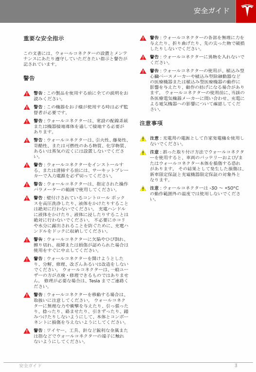
重要な安全指示
この文書には、ウォールコネクターの設置とメンテナンスにあたり遵守していただきたい指示と警告が記されています。
警告
警告 : この製品を使用する前に全ての説明をお
読みください。
警告 : この機器をお子様が使用する時は必ず監
督者が必要です。
警告 : ウォールコネクターは、常設の配線系統
または機器接地導体を通して接地する必要があります。
警告 : ウォールコネクターは、引火性、爆発性、
苛酷性、または可燃性のある物質、化学物質、あるいは蒸気の近くには設置しないでください。
警告 : ウォールコネクターをインストールす
る、または清掃する前には、サーキットブレーカーで入力電源を必ず切ってください。
警告 : ウォールコネクターは、指定された操作
パラメーターの範囲で使用してください。
警告 : 壁付けされているコントロール ボック
スを高圧洗浄したり、液体をかけたりすることは絶対に行わないでください。 充電ハンドル
に液体をかけたり、液体に浸したりすることは絶対に行わないでください。 不必要にホコリ
や水分に露出されることを防ぐために、充電ハンドルをドックに収納してください。
警告 : ウォールコネクターに欠陥やひび割れ、
擦り切れ、故障または損傷が認められた場合は使用をすぐに中止してください。
警告 : ウォールコネクターを開けようとした
り、分解、修理、改ざんあるいは改造をしないでください。 ウォールコネクターは、一般ユー
ザーの方が点検・修理できるものではありません。 修理が必要な場合は、Tesla までご連絡く
ださい。
警告 : ウォールコネクターを移動する場合は、
取扱いに注意してください。 ウォールコネク
ターに無理な力や衝撃を与えたり、引っ張ったり、捻ったり、絡ませたり、引きずったり、踏みつけたりしないようにして、本体とコンポーネントに損傷を与えないようにしてください。
警告 : ワイヤー、工具、針など鋭利な金属また
は指などでウォールコネクターの端子に触れないようにしてください。
警告 : ウォールコネクターの各部を無理に力を
与えたり、折り曲げたり、先の尖った物で破損したりしないでください。
警告 : ウォールコネクターに異物を入れないで
ください。
警告 : ウォールコネクターの使用が、植込み型
心臓ペースメーカーや植込み型除細動器などの医療機器または植込み型医療機器の動作に影響を与えたり、動作の妨げになる場合があります。 ウォールコネクターの使用前に、当該の
各医療電気機器メーカーに問い合わせ、充電による電気機器への影響について確認してください。
注意事項
注意 : 充電用の電源として自家発電機を使用し
ないでください。
注意 : 誤った取り付け方法でウォールコネクタ
ーを使用すると、車両のバッテリーおよび/またはウォールコネクター本体を損傷する恐れがあります。 その結果として発生した損傷は、
新車限定保証と充電機器限定保証の対象外となります。
注意 : ウォールコネクターは -30 ~ +50°Cの動作範囲外の温度では使用しないでください。
安全ガイド
安全ガイド 3

注記
注 : ウォールコネクターの充電ケーブルは、踏まれ
たり、足に引っかかったり、車で乗りあげたり、または損傷や無理な力をかけることがないようにしてください。
注 : ウォールコネクターのいかなるコンポーネント
も溶剤を使って洗浄しないでください。 ウォール
コネクターの外面、充電ケーブル、充電ケーブルのコネクター端子など、乾いた布を使用して定期的に拭いてホコリや汚れを落としてください。
注 : 取り付け作業中に誤って回路基板を損傷しない
よう注意してください。
安全ガイド
4

ウォールコネクターの最大定格は、200V AC 単相で 16kW または 80 アンペアです。 車両は、200V 単相で
充電可能です。
項目 仕様
電圧および配線 200V AC 単相: L1、 L2、 アース
電流 設置する電気工事士が設定を行う
最大出力: 80A、72A、64A、56A、48A、40A、36A、
32A、28A、24A、20A、16A、12A
周波数 50/60 Hz
ケーブル長 2.6 m と 7.4 m
ウォールコネクター寸法 高さ: 380 mm
幅: 160 mm
奥行: 140 mm
トップエントリーブラケット寸法 高さ: 275 mm
幅: 130 mm
奥行: 50 mm
重量(ブラケット含む) 9 kg
動作温度 -30°C ~ 50°C
保管温度 -40°C ~ 85°C
エンクロージャの保護等級 Type 3R
機関承認 アメリカ合衆国およびカナダに関して、ファイル番号E354307、FCC パート 15 として、cULus に記載。
仕様
仕様 5

遮断器規格オプション
最速の充電を行うには、各相ごとに 100A 規格の単
相サーキットブレーカーを使用してください。 設置場所によっては、この電力レベルが利用できないことがあります。 そのため、ウォールコネクターの
サーキットブレーカーを 15A から 100A 規格に変
更できます(動作電流の設定20 ページの を参
照)。
注 : 高いアンペアを受け入れるには、Tesla 車両をオ
プションの車載充電装置に合わせて設定する必要があります。 あなたの車両の車載充電能力について
質問がある場合は Tesla までご連絡ください。
自己監視と復旧
ウォールコネクターには接地監視回路が備わっており、安全な接地接続の有無を常時チェックし、障害から自動で復旧します。 手動でのテストやリセッ
トは必要ありません。
地絡や電力サージなどの一時的な障害からは、自動で復旧します。 残留電流障害が発生して充電が中
断した場合、ウォールコネクターは自動で障害の解決および充電の再開を試みます。
ただちに 2 度目の障害を感知した場合、ウォールコ
ネクターは充電を再試行する前に 15 分間待機しま
す。 このプロセスを 4 回繰り返し、すべてが失敗に
終わった場合は電力を切断し、それ以上の充電を試行しません。 この場合は、フロントパネルに赤色の
エラーランプが点灯します(トラブルシューティン
グ22 ページのを参照)。 赤色のエラーランプが
点灯した場合は、ウォールコネクターのサーキットブレーカーで電源を一度切り、再投入することをお薦めします。
赤色のエラーランプが点灯した時には、RESET ボタ
ンでウォールコネクターをリセットすることもできます(リセット25 ページのを参照)。
停電
停電が発生した場合、ウォールコネクターは電力の復帰にともなって自動的に充電を再開します。 電力の復帰時に充電ケーブルが車両に接続されている場合は、ランプが点滅しウォールコネクターは約 15秒から 3 分間、充電ケーブルに通電しません。 これ
により、異なるタイミングで複数の車両が充電を再開し、一度に大きなサージ電流が送電網に流れることを防ぎます。
ロードシェアリング
最大 4 台のウォールコネクターを 1 本の回路に接続
するできるので、自宅で複数の車両を一度に充電することができます(付録 B: ロードシェアリングの接
続オプション28 ページのを参照)。
機能
6

最低必要条件
ウォールコネクターの設置に必要な作業:
• 既存の電気的負荷を計算して最大動作電流を決定します。
• 距離を計算して電圧降下を最小限に保ちます。
• 銅製の導体のみを使用してください。
• 使用する導体サイズは、地域の配線規則に従ってください。 選択するケーブルは最大 80 Aの一定負荷に対応している必要があります。
• 保護装置を使用してください。 回路保護装置
には、選択した電気負荷に適した残留電流装置(RCD) および過電流保護が必要です。
注 : 設置作業が地域の規定に適合するよう電気工事
士に相談してください。
配線
警告 : ウォールコネクターは単相機器です。 3相すべてを 3 相入力フィードに接続しないで
ください。
警告 : ウォールコネクターを取り付ける前に、
設置現場で利用できる電源の種類を確認します。
注 : 使用する 2 相は、それぞれ 100V 必要です この
図は、最も一般的に使用される配線フォーマットです。
注 : 図に示している L1、L2 と接地出力は、ウォール
コネクターの入力に対応してます。
アース接続
中性線からアース接地までの接続は必ず配電盤で行ってください。 電気設備が接地されていない場合
は、接地棒を近くに設置しなければなりません。接地棒は必ず主ブレーカーパネルの接地バーに必ず接続し、その点で中性線を接地に接続します。
200V 単相
L2
L1
100V
100V
GND
200VNEUTRAL(NOT USED)
注 : この図は例示のために描かれています。
208V 3 相 Y 結線
Y 結線の 2 次側では、任意の足 2 本を使用して
208V をウォールコネクターに供給することができ
ます。 例えば、L1 と L2、または L1 と L3、または
L2 と L3 など。 使用する 2 相は、中性に対してそ
れぞれ 120V 必要です
注 : 通電している中性は必要ありません。
120V 208V
120V
L1
ニュートラル(未使用)
L3 (未使用)
L2 (未使用)
グラウンド
注意 : 未使用の足(図の L3)は、開放しておく
必要があります。 ニュートラルバーまたはア
ースに接続しないでください。
注意 : 3 相の中央極(通常中性線に使用される)
は一箇所でアース接続されます。 通常はブレ
ーカーパネルで接続されます。
設置作業の計画
設置作業の計画 7

240V 3 相 デルタ結線
デルタ結線では、1 つの足をセンタータップし、セン
タータップのいずれか片側の 2 相のみ使用します。
使用される 2 相は中性に対してそれぞれ 120V 必要
です。
1 本の足で必要な電力を供給可能かどうかは、トラン
ス メーカーの資料でご確認ください。
注 : ウォールコネクターの接触器が閉じるのは、ト
ランス 2 次側の中性点に接続した接地線をウォール
コネクターが検出した場合のみです。
L1
L2
グラウンド
120V
120V
240V
L3 (未使用)
ニュートラル
(未使用)
注意 : デルタ結線の第 3 線(図の L3)は中性
に対して 208V であり、「スティンガー」と呼
ばれることがあります この第 3 線を使用しな
いでください。
注意 : 1 つの足をセンタータップすることな
く、3 相デルタ結線のトランスの 2 次側を使用
しないでください。 必要な接地接続に使用で
きる中性点はありません
277V 3 相 Y 結線
Y 結線の 2 次側では、任意の足 2 本を使用して
277V をウォールコネクターに供給することができ
ます。 例えば、L1 と N、または L2 と N、または
L3 と N など。
277V 480V
277V
L1
ニュートラル
L3 (未使用)
L2 (未使用)
グラウンド
注意 : 未使用の足(図の L2 と L3)は、開放し
ておく必要があります。 中性またはアース接
地に接続しないでください。
注意 : 3 相の中央極(通常中性線に使用される)
は一箇所でアース接続されます。 通常はブレ
ーカーパネルで接続されます。
設置作業の計画
8

サーキットブレーカーの選定
ウォールコネクターを接続するサーキットブレーカーの定格容量を決定するには、設置場所で使用可能なアンペア数を調べてください。
ウォールコネクターには内部ロータリースイッチが搭載されているので、動作電流を調整することができます(動作電流の設定20 ページのを参照)。 サーキットブレーカーの定格連続電流は以下: 12、16、20、24、28、32、36、40、48、56、64、72、80A。
注 : ウォール コネクターを取り付ける際には、
Extension Regulation 3605-3-3 で指定されてい
るサーキット ブレーカーの定格電流を参照してく
ださい。
ウォールコネクターの最適な設置場所
充電ケーブルが充電ポートに届くように、車両の駐車位置からウォールコネクターの設置位置を決定します。
• 屋内ガレージで、車両の充電ポートがある側。
• 風通しの良い場所。 囲まれた箱の中や熱の出
る機器の近くに取り付けることは避けてください。
注 : ウォールコネクターは屋外で使用することがで
きます。 防雨対策することが推奨されますが、必須
ではありません。
設置作業の計画
設置作業の計画 9

設置作業における考慮事項
ウォールコネクターに配線を取り込む方法には 3 つの方式があります。 コンジットの経路によりどの方法が
最適か決まります。 コンジットを床または壁に這わす場合は、ボトムエントリー方式を使用します。 コンジ
ットを壁内に這わす場合は、リアエントリー方式を使用します。 コンジットを天井裏から下ろす場合は、トッ
プエントリー方式を使用します。
注 : このマニュアルを通して、「コンジット」とは配線管のことを示す名称として使用されています。 コンジ
ットを使用しない地域(例えば欧州など)では、地域の規定で可能であれば、被覆された配線で構成されるケーブルをコンジットの代用として使用することができます。
付随するガイドライン:
• コンジットの開口部のサイズは、32 mm コンジットです。
• 適切なサーキットブレーカーを使用します。
• 防水性を保つため、ケーブルグランドを使用します。
• UL 規格のコンジットハブを使用してください。
ボトムエントリーまたはリアエントリー
設置作業の計画
10

トップエントリー
設置作業の計画
設置作業の計画 11

商品梱包箱の中には全ての取り付け方法が行える部品と本マニュアルが含まれています。 いずれかの部品に
損傷があったり、見当たらない場合は Tesla にご連絡ください(お問い合わせ:26 ページのを参照)。
注 : ここで示すのは、提供される段ボール製テンプレートではありません。
1 2 3 4
5 6 7 8 9
10 11 12 13 14
番号 名称 (数量)
1 壁面コネクター
2 トップエントリーブラケット *
3 ロープロファイルブラケット**
4 ロープロファイルブラケットネジ (2) **
5 ボトムエントリー/リアエントリー電源コンジットプラグ
6 ボトムエントリー/リアエントリー信号コンジットプラグ
7 トップエントリー信号コンジットプラグ *
8 トップエントリー電源コンジットプラグ *
9 ボトムコンジットシールガスケット *
10 上部ハウジング取付ネジ化粧カバー (2)
内容物の確認
12

番号 名称 (数量)
11 下部ハウジング取付ネジ化粧カバー (2)
12 下部ハウジング取付ネジ (2)
13 上部ハウジング取付ネジ (2)
14 トップエントリーブラケット取付ネジ (2)*
* トップエントリー方式にのみ使用する部品です。
** ボトムエントリーまたはリアエントリー方式にのみ使用する部品です。
内容物の確認
内容物の確認 13

必要な工具と材料
ウォールコネクターを設置する前に、以下の工具と材料を用意してください。
• 鉛筆またはマーカー
• 穴パンチ(オプション。段ボール製テンプレートに穴を開けるため)
• ワイヤーストリッパー
• 電圧計またはデジタルマルチメーター(設置場所で AC 電圧を計測するため)
• プラスドライバー
• 小さいマイナスドライバー
• 大きなマイナスドライバー
• T20 トルクスドライバー(セキュリティネジ対応)
• T10 トルクスドライバー
• M20 および M32 ケーブルグランド(別名シーリングハブ)
• フェルール端子(フェルール径は使用する電線の太さと構成に合ったもの)
• 配線(ウォールコネクター間でツイストペア通信ケーブルは最大 15 m で使用してください)
注 : 干渉する可能性を少なくするためにシールドケーブルを使用することが推奨されます。
• レベル
• ドリル
設置手順の概要
警告 : 取り付け現場に適切な上流回路遮断器をインストールした後、作業を続行する前に必ず電気が切ら
れていることを確認してください。
確認できたら、以下の手順に従ってウォールコネクターを設置します。
• リアエントリー/ボトムエントリー方式配線のためのロープロファイルブラケットの取付け15 ページの
• トップエントリー方式のためのトップエントリーブラケットの取付け16 ページの
• 本体取付け前の準備17 ページの
• 配線の接続18 ページの
• 動作電流の設定20 ページの
• カバーの取付けと電源投入21 ページの
設置手順
14

リアエントリー/ボトムエントリー方式
配線のためのロープロファイルブラケットの取付け
以下に示すように、ウォールコネクターをリアまたはボトムから配線するには、ロープロファイルブラケットを使用してください。
1. ロープロファイルブラケットを壁にあて、取付けネジの位置に印をつけます。
• 水準器で水平を確かめます。
• 穴は 114 mm の間隔を空けます。
• 。 室内設置の場合は、床から 45 cm 以上
に、屋外設置の場合は、60 cm の高さにな
るよう取付けてください。
• リアエントリーコンジットを使用する場合は、左端または右端いずれかの 2 つの取付
穴を使うとコンジットが間柱に干渉しません。
• ボトムエントリー方式のコンジットを使用する場合は、中央の 2 つの取付穴を使用し
ます。
注 : ブラケットの取り付ける高さを決める際は
ご注意ください。 考えうる限りの影響を避け
るように設置を行ってください。
2. 壁の材質を使用してください。 中空壁や石製
の柱などに取り付ける場合は、安全に固定できる長さを備え、少なくとも 36 kg を支えられる
留め具を使用してください。
設置手順
設置手順 15
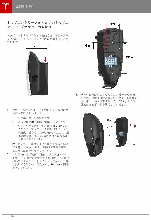
トップエントリー方式のためのトップエ
ントリーブラケットの取付け
トップエントリーブラケットを使うと、下図のように上部からウォールコネクター内に配線することができます。
1. 段ボール製テンプレートを壁にあて、取付けネジの位置に印をつけます。
• 水準器で水平を確かめます。
• 穴は 155 mm の間隔で開けてください。
• ウォールコネクターが床から 150 cm 以下
になるようブラケットを取付けます。 室内設置の場合は、床から 45 cm 以上に、屋
外設置の場合は、 60 cm の高さになるよ
う取付けてください。
注 : ブラケットの取り付ける高さを決める際は
ご注意ください。 考えうる限りの影響を避け
るように設置を行ってください。
2. (オプション)予備用に取付穴がもう 2 つあり
ます。 この取付穴を使用する場合は、穴を塞い
でいるプラスチックをマイナスドライバーで押し出してください。 取付穴は、70 mm の間隔
が空いています。
3. 壁の材質を使用してください。 中空壁や石製
の柱などに取り付ける場合は、ウォールコネクターをしっかり固定するために 36 kg までの
強度があるボルトを使用してください。
設置手順
16

本体取付け前の準備
これらの指示に従い、カバーを外して、配線をウォールコネクターに通します。
1. T10 トルクスドライバーを使用して、前面カバ
ー下部のネジを一つ取り外します。 マイナス
ドライバーを使用して両端と最上部にあるスナップを注意しながら外し、カバーを完全に外します。 再度取り付けるまでネジとカバーを大
切に保管してください。
2. T20 セキュリティピン付トルクスドライバー
を使用して、シールカバーにあるネジを 6 つ取
り外します。 シールカバーを注意して外し、リ
ボンケーブルを取り外します。 再度取り付け
るまでネジとカバーを大切に保管してください。
注意 : シールカバーがリボンケーブルから
ぶら下がらないようにしてください。 リボンケーブルまたは端子を損傷する恐れがあります。
3. トップエントリー方式では、配線の接続18 ペ
ージので示すようにトップエントリーブラケットの端子台に配線を接続してから、このページに戻り次のステップに進みます。 バックエン
トリーまたはボトムエントリー方式は、次のステップにスキップしてください。
4. マウントタブ 4 つの位置をしっかり合わせてウ
ォールコネクターをブラケットに押さえます。
5. T20 トルクスドライバーを使用して、2 つの上
部本体取付ネジを取り付けます。 ネジ化粧カ
バーを押し込んで取り付けます。
6. T20 トルクスドライバーを使用して、2 つの下
部本体取付ネジを取り付けます。 ネジ化粧カ
バーを押し込んで取り付けます。
設置手順
設置手順 17
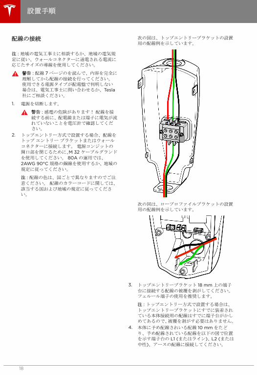
配線の接続
注 : 地域の電気工事士に相談するか、地域の電気規
定に従い、ウォールコネクターに通電される電流に応じたサイズの導線を使用してください。
警告 : 配線 7 ページのを読んで、内容を完全に
理解してから配線の接続を行ってください。使用できる電源タイプが配電盤で判明しない場合は、電気工事士に問い合わせるか、Tesla社にご相談ください。
1. 電源を切断します。
警告 : 感電の危険があります! 配線を接
続する前に、配電線または端子に電気が流れていないことを電圧計で確認してください。
2. トップエントリー方式で設置する場合、配線をトップ エントリー ブラケットまたはウォール
コネクターに接続します。 電源コンジットの
開口部を閉じるために、M 32 ケーブルグランド
を使用してください。 80A の運用では、
2AWG 90°C 規格の銅線を使用するか、地域の
規定に従ってください。
注 : 配線の色は、国ごとで異なりますのでご注
意ください。 配線のカラーコードに関しては、
該当する国および地域の規定に従ってください。
次の図は、トップエントリーブラケットの設置用の配線例を示しています。
次の図は、ロープロファイルブラケットの設置用の配線例を示しています。
3. トップエントリーブラケット 18 mm 上の端子
台に接続する配線の被覆を剥がしてください。フェルール端子の使用を推奨します。
注 : トップエントリー方式で設置する場合は、
トップエントリーブラケットにすでに装着されている本体接続用の配線はすでに端子台がかしめてあるので、被覆を剥がす必要はありません。
4. 本体に予め配線されいる配線 10 mm をたど
り、予め配線されている配線を以下の図で位置を示す端子台の L1 (またはライン)、L2 (または
中性)、アースの配線に接続してください。
設置手順
18

注意 : 各ワイヤストランドを切断し、それ
ぞれを各端子台に完全に差し込んでください。
5. 各端子台を以下の推奨トルクで締め付けます:
• トップエントリーブラケット上の端子台の締め付けトルクは、4.0 N-m です。
• 本体にある端子台の締め付けトルクは、3.8N-m (33 in-lb)です。
• 本体にあるアース用端子台の締め付けトルクは、2.0 N-m です。
6. マルチメーターを使用して配線ミスがないことの点検をし、ブレーカーを入れる前に短絡がないことを確認してください。
設置手順
設置手順 19

動作電流の設定
動作電流の設定は、以下の手順で行ってください。下の図は、動作電流とロータリースイッチの拡大図です。
警告 : ディップスイッチまたはロータリースイ
ッチを設定または変更する前に、必ず電源をOFF にしてください。 電源が ON の状態で
は、システムはこれらのスイッチの設定変更を認識しません。また、感電の危険性もあります。
1. 電源を OFF にします。
2. 絶縁性の物(プラスチックのペン等)を使用して、ディップスイッチを以下の通り設定してください:
• スイッチ位置 1:
• ラインからラインへの接続 (200V)は、ディップスイッチを下にします。
• ラインからニュートラルへの接続(277 V) は、ディップスイッチを上(ON の位置) にします。
警告 : ディップスイッチを設定する前に、電源タイプを確認してください。
• スイッチ位置 2:
• ディップスイッチ 2 の位置は必ず常に
上にしてください。
ディップスイッチ
上(オン) 下
1 の位置 ラインからニュートラル(277V)
ラインからライン (200V)
2 の位置 ノーマル 適用外
3. ご使用のサーキットブレーカーに適した電流設定をするためにロータリースイッチを設定します。
小型のマイナスドライバを使用して、適切なサーキットブレーカ定格設定にロータリスイッチを調整します。 以下の表は、標準的なサーキッ
トブレーカーに対応するロータリースイッチの設定です。
ロータリースイッチの位置
最大出力電流 サーキットブレーカー
0 テストモード N/A
1 12A 15A
2 16A 20A
3 20A 25A
4 24A 30A
5 28A 35A
6 32A 40A
7 36A 45A
8 40A 50A
9 48A 60A
A 56A 70A
B 64A 80A
C 72A 90A
D 80A 100A
無効 N/A
F スレーブモード
N/A
4. リボンケーブルをシールカバーに再度取り付けます。
5. シールカバーを取り付けます。 T20 セキュリ
ティピン付トルクスドライバーを使用して一番上のネジのみを取り付けてシールカバーを仮止めします。
6. 電源を ON にします。
7. 正しく設置できた場合には、LED があるパター
ンで短く連続的なパターンで緑色に点滅した後、最終的に最上部の LED が緑色に点灯しま
す。 LED が赤色に点灯または点滅する場合は、
トラブルシューティング22 ページのを参照
しすぐにエラーを解決してください。
注 : 点滅するランプのパターンを再確認する場
合は、リセットボタンを 5 秒間長押ししてくだ
さい。
8. 電源を OFF にします。
9. ウォールコネクター内側にある取付者ラベルに連絡先を記入してください。
設置手順
20
E

カバーの取付けと電源投入
1. T20 トルクスドライバー(セキュリティネジ対
応)を使用して、シールカバーに残りのネジを取り付けます。 ネジを締めきる前にカバーの
位置が正しく揃っているか確認します。
2. 前面カバーを上部のラッチ部分から順に取り付けます。 両側のスナップを嵌め、取付けタブを
本体の下部に合わせます。
3. T10 トルクスドライバーを使用して、外側カバ
ーの下部を本体にネジ止めします。
4. 使用されない開口部は電源/信号コンジットプ
ラグで塞いでください。
注 : ウォールコネクター内部が見える隙間がな
い状態にし、外部環境から完全に密閉する必要があります。
5. 電源を ON にします。 正しく設置できると、
LED が連続して点滅し、その後上部の LED が緑色に点灯します。 LED が点灯または点滅す
る場合は、続行する前にエラーを解決してください(トラブルシューティング22 ページのを
参照)。
注 : 点滅するライトのパターンを再確認する場
合は、リセットボタンを 5 秒間長押ししてくだ
さい。
6. ウォールコネクターが正しく作動し選択した動作電流で充電できるかを確認するために車両を充電します。 充電方法については、車両に装備
されているオーナーズマニュアルをご参照ください。
設置手順
設置手順 21

緑色ライト 黄色ライト 赤色ライト 自動再試行 説明 対応策
一番上のライトがオン
オフ オフ 該当なし 電源オン。 ウォール
コネクターの電源は入っていますが、車両を充電していません。
該当なし
ライトが流れるように点灯
オフ オフ 該当なし ウォール コネクター
が車両を充電しています。
該当なし
ライトが流れるように点灯
1 回点滅 オフ 該当なし 車両用コネクターで高温が検出されたので充電電流が減少されました。
車両用コネクター(充電ハンドル)が車両の充電ポートに完全に挿入されていて、何かで覆われていたり、他の熱源が近くにないことを確認してください。 通常の周囲温
度(38°C 以下)で問題が
解決されない場合は、Tesla までご連絡くださ
い。
ライトが流れるように点灯
2 回点滅 オフ 該当なし 壁コンセントまたはウォールコネクターの入力ターミナルで高温が検出されたので充電電流が減少されました。
壁 コンセントが使用さ
れている場合、レセプタクルに完全に挿入されていて、何かで覆われていたり、他の熱源が近くにないことを確認してください。 ウォールコネク
ターが壁側電源に直接接続されていて、何かで覆われていたり、他の熱源が近くにないことを確認してください。 通常の
周囲温度(38°C 以下)で
問題が解決されない場合は、Tesla までご連絡くだ
さい。
ライトが流れるように点灯
3 回点滅 オフ 該当なし ウォールコネクター内部で高温が検出されたので充電電流が減少されました。
ウォールコネクターが何かで覆われていたり、他の熱源が近くにないことを確認してください。通常の周囲温度(38°C 以下)で問題が解決されない場合は、Tesla までご連
絡ください。
トラブルシューティング
22

緑色ライト 黄色ライト 赤色ライト 自動再試行 説明 対応策
オフ オフ 1 回点滅 15 分後、4 回
まで
漏電。 安全でない経
路から漏電しています。 ラインからアー
スまたは中性からアースで不良の恐れがあります。
充電ハンドルを車両から外してください。 再度
接続して再試行してください。 問題が解消され
ない場合は、ウォールコネクターのサーキットブレーカーをオフにして、10 秒待ってください。
サーキットブレーカーをオンにして、再試行してください。 不具合が解
消しない場合は、Tesla に連絡してください。
オフ オフ 2 回点滅 1 分後、4 回ま
で
ウォールコネクターで接地接続が検出されません。
ウォールコネクターが正しく接地されていることを確認してください。不明な場合、サーキットブレーカーまたは分電盤ボックスが正しく接地され、ウォールコネクターが正しく接続されていることを確認するよう電気工事士に相談してください。
オフ オフ 3 回点滅 No 入力側配線ミス: ライ
ンと中性が反対に接続されている可能性があります。
壁側電源とウォールコネクター間の入力配線が誤って接続されています。電気工事士にご相談ください。
オフ オフ 4 回点滅 1 分後、4 回ま
で
過電圧または減電圧保護。
ウォールコネクターのサーキットブレーカーの正しい電圧について電気工事士にご相談ください。
オフ オフ 5 回点滅 1 分後再試行
(回数に制限無し)
過電流保護。 車両側で充電電流設定を下げてください。 問題
が解消されず、充電している車両が Tesla 製の場
合は、Tesla までご連絡く
ださい。
オフ オフ 6 回点滅 1 分後再試行
(回数に制限無し)
パイロット障害: パイ
ロットレベルが正しくありません
可能な場合、車両を他のウォールコネクターに繋げるか、アクセサリーのモバイルコネクターを繋げます。問題が解消されない場合は、Tesla までご
連絡ください。
トラブルシューティング
トラブルシューティング 23

緑色ライト 黄色ライト 赤色ライト 自動再試行 説明 対応策
一番上のライトがオン
オフ 1 回点滅 No 過熱保護(ラッチオフ) ウォールコネクター、車両コネクター、壁コンセント(使用されている場合)が、何かで覆われていたり、他の熱源が近くにないことを確認してください。 通常の周囲温
度(38°C 以下)で問題が
解決されない場合は、Tesla までご連絡くださ
い。
一番上のライトがオン
オフ 2 回点滅 No Tesla 製でない車両を
対応していない入力分配器に接続を試みる。
対応している入力分配器:単相分配器または400V、3 相分配器。
一番上のライトがオン
オフ 3 回点滅 No 誤ったロータリースイッチ設定。
電気工事士にご相談ください。
一番上のライトがオン
オフ 4 回点滅 適用外 サーキットブレーカー共有ネットワーク: 1台以上のウォールコネクターがマスターに設定されています。
いずれかのウォールコネクターをスレーブに設定してください。
一番上のライトがオン
オフ 5 回点滅 適用外 サーキットブレーカー共有ネットワーク: 3台以上のウォールコネクターがスレーブに設定されています。
1 台以上のウォールコネ
クターを異なるサーキットに移し、このサーキットブレーカー共有ネットワークから外してください。
一番上のライトがオン
オフ 6 回点滅 適用外 サーキットブレーカー共有ネットワーク: ネットワークに共有されているウォールコネクターの最大通電能力が異なります。
Tesla に連絡してくださ
い。
オフ オフ 赤色で点灯 No ウォールコネクターハードウェアの不良。以下を含む可能性のある不良:
• コネクターの障害
• CCID 電気回路構
成で自己診断に失敗
• その他可能性のある不良は、MCU、
3V3 出力、または
端子センサーがあります。
Tesla に連絡してくださ
い。
トラブルシューティング
24

リセット
エラーが原因で赤色エラーライトが点灯または点滅してからそのエラーを解決した場合、ウォールコネクターをリセットして正しく動作させるよう RESET ボタンを使用することができます。
1. 2~3 秒程度 RESET ボタンを押します。 最上部のライトの色が赤色から緑色に変わったら RESET ボタ
ンを離します。 このリセット方法では、エラーメッセージはクリアされますがウォールコネクターは強制
的に再起動されません。
2. まれにある状況では、入力電力を再利用せずにウォールコネクターを強制的に再起動する必要がある場合が稀にあります。 RESET ボタンを 5 秒間押してください。 最上部のライトの色が赤色から緑色に変わ
ったら RESET ボタンを離します。 最上部のライトは緑色で点灯します。 ライトが赤色の点滅に戻った
ら、問題は解決されていません。
トラブルシューティング
トラブルシューティング 25

1. 電源を OFF にします。
警告 : 感電の危険性に注意してください。
配線を接続する前に、配電線または端子に電気が流れていないことを電圧計で確認してください。
2. 絶縁性の物(プラスチックのペン等)を使用して、ディップスイッチ設定およびブレーカーのシェアリング設定を調整してください(動作電
流の設定 20 ページのを参照)。
3. 小型のマイナスドライバーを使用してロータリースイッチを "0" の位置に設定し、ウォールコ
ネクターをテストモードにします。
警告 : ディップスイッチまたはロータリー
スイッチを設定または変更する前に、必ず電源を OFF にしてください。 電源が
ON の状態では、システムはこれらのスイ
ッチの設定変更を認識しません。また、感電の危険性もあります。
4. リボンケーブルをシールカバーに再度取り付けてください。
5. T20 トルクスドライバー(セキュリティネジ対
応)を使用して一番上のネジのみを取り付けてシールカバーを仮止めします。
6. サーキットブレーカーをオンにします。
7. 赤色の LED が、LED ディスプレイのシーケン
スの後に点灯するかどうか確認します。点灯する場合は取り付け状態に問題があります。
8. コンタクターまたはリレーの開閉するクリック音を聞きます。
9. 緑色のストリーミング LED を確認します(5 秒
間)。
一番上の緑色の LED がオンに復帰し、赤色の
LED が点滅します(3 回)
注 : 点滅するライトのパターンを再確認する場
合は、リセットボタンを 5 秒間長押ししてくだ
さい。
10. 回路遮断器をオフにします。
11. シールカバーネジとシールカバーを取り外します。 リボンケーブルを外します。
注意 : シールカバーがリボンケーブルから
ぶら下がらないようにしてください。 リボンケーブルまたは端子を損傷する恐れがあります。
12. 適切な設定にロータリー スイッチの位置を変
えます(動作電流の設定 20 ページのを参照)。
13. リボンケーブルをシールカバーに再度取り付けてください。
14. 全てのネジを取り付け、前面カバーを再度取り付けます(カバーの取付けと電源投入 21 ページ
のを参照)。
付録 A: 正常な動作の確認
付録 A: 正常な動作の確認 27

ウォールコネクターにはウォールコネクター間で通信する機能があり、最大利用可能負荷を最大 4 台の
ウォールコネクターに分散することができます。このローカルネットワークに使用される配線は、主電源ケーブルのコンジットを共有しているか、専用のコンジットに収められています。
ウォールコネクターは、デイジーチェーン構成で直列に接続できます。
注 : 屋外に設置する時は、ウォールコネクターへの
水の浸入を防ぐために細心の注意を払ってください。
注 : 取り付け作業が地域の規定に適合しているかに
ついては、電気工事士にご相談ください。
複数のウォールコネクターをデイジーチ
ェーン接続する
以下に示すように、各ウォールコネクターには通信配線用の端子台が 1 個設けられています。 端子台の
左側が入力端子で、右側が出力端子です。
1. アウトからインにケーブルを接続してデイジーチェーンネットワークを構成します。接続される各ウォールコネクター間を接続する時は、必
ずプラスとプラスを接続して、マイナスとマイナスを接続してください(通信ケーブルの配線
例29 ページのを参照)。
• 各ウォールコネクター間の信号配線は信号コンジットを使用して配線しなければなりません。 M20UL 規格のコンジットハブを
使用して信号配線用コンジットの開部を密閉します。
• 信号配線は、電源用コンジット内に電源配線と共に配線されるので、信号配線の絶縁性能評価は、電源配線のものと同等もしくはそれ以上でなければなりません。
• ウォールコネクター間の距離は、最大 15 mです。
• 信号配線にはツイストペアケーブルを使用してください。
注 : 干渉する可能性を少なくするためにシール
ドケーブルを使用することが推奨されます。
2. 最大出力電流に応じてロータリースイッチの位置を 1 から 8 の間に設定して、ウォールコネク
ターの 1 台をマスターとして設定してくださ
い。 ロータリースイッチの位置を F に設定し
て、最大 3 台のウォールコネクターをスレーブ
として設定してください。ロードシェアリングネットワークでは、マスターとして割り当てられるユニットは 1 台のみです(動作電流の設定
20 ページのを参照)。
3. ロードシェアリングネットワークが正しくインストールされたことをウォールコネクター内にある LED インジケータで確認します。 サーキ
ットブレーカーを初めて起動する時、緑色のライトが 5 秒間点灯し正しくインストールされた
ことを以下のように示します:
緑色ライト 黄色ライト
赤色ライト
これが示すのは・・・
オン(上と下)
オフ オフ マスターユニット
オン(下) オフ オフ スレーブユニット
付録 B: ロードシェアリングの接続オプション
28

通信ケーブルの配線例
ウォールコネクター (1)マスター
ウォールコネクター (2)スレーブ
ウォールコネクター (3)スレーブ
ウォールコネクター (4)スレーブ
8
ロータリースイッチ
D+ D- D+ D-イン アウト
Fロータリースイッチ
D+ D- D+ D-イン アウト
Fロータリースイッチ
D+ D- D+ D-イン アウト
Fロータリースイッチ
D+ D- D+ D-イン アウト
付録 B: ロードシェアリングの接続オプション
付録 B: ロードシェアリングの接続オプション 29

一般条件
下記の除外条項および制限条項に従い、充電機器限定保証はテスラが製造し支給したウォール コネク
ター、モバイル コネクターまたは充電アダプター
の、お客様への請求書の日付から 12 ヶ月以内 に通
常の使用条件下で発生する製造時欠陥を是正するための返金、修理または交換を対象とします。 テスラ
によるテスラ車両の初期購入および納車に含まれるテスラ コネクターまたはアダプターは、新車限定保
証の条件に従い、4 年間または累計走行距離が
80,000 km に達するまでのいずれか先に充足され
る期間について、新車限定保証の基本車両限定保証の項の対象になります。
この充電機器限定保証は、以下を含むがこれらに限定されない、直接的または間接的に、通常の摩耗または劣化、乱用、誤用、放置、事故、不適切なあるいは適切な使用、メンテナンス、保管もしくは輸送の欠如によって発生したいかなる損害または故障を対象としません。
• テスラコネクターまたはアダプターに付随する文書に記載される指示、メンテナンス、警告に従わない場合。
• テスラ コネクターまたはアダプターに衝撃を
加える物体、不良のまたは損傷した電気配線、ジャンクションボックス、サーキットブレーカー、レセプタクル、もしくは電源コンセント、環境または火災、地震、水害、雷撃などの環境条件を含むがこれらに限定されない不可抗力を含む、これらに限定されることのない外的要因。
• 全体的外観または塗装の欠け、傷、へこみ、ひび割れなどの損傷。
• 本充電機器限定保証対象となる欠陥発見時におけるテスラへの連絡不履行。
• テスラコネクター、アダプターまたはいずれかの部品の修理、改変または改造、あるいは権限のない、もしくは承認されていない人物または施設により製造された部品またはアクセサリーの設置または使用。
• テスラ純正品以外のアクセサリーまたは部品の使用を含む、適切な修理もしくはメンテナンスの欠如または不履行、および
• 商業目的での使用。
テスラはすべてのメンテナンス、サービス、または修理をテスラサービスセンターまたはテスラ認定修理施設で実施することを要請していませんが、メンテナンス、サービス、または修理の不履行、あるいはそれらが適切に実施されないことにより、本充電機器限定保証が無効になる、もしくは保証範囲から除外される場合があります。 テスラサービスセン
ターおよびテスラ認定修理施設は、コネクターおよびアダプターに関する専門的訓練、専門知識、工具および備品を備えており、場合によっては、テスラコネクターおよびアダプターを修理するために認定された人員を雇用することができる、もしくはテスラコネクターおよびアダプターの修理を実施できる唯一の認定または有資格の施設となります。 テス
ラは、本充電機器限定保証にもとづき、保証が無効になること、または保証範囲から除外されることを防ぐため、メンテナンス、サービス、および修理はすべてテスラ サービスセンターまたはテスラ認定
修理施設で行うことを強く推奨します。
責任の制限
本充電機器限定保証は、お客様のテスラコネクターまたはアダプターに関する唯一の明示的保証です。商品適格性または適商品質、特定の目的への適合性、もしくは耐久性の黙示的保証および条件、または取引の過程もしくは商慣習によって生じる黙示的保証および条件を始め、これらに限定することなく、適用される当該地域の法律または連邦法規あるいはその他の法律もしくは衡平法上の権利のもとに生じる黙示的および明示的保証と条件は、法の許す範囲で排除されるか、本充電器限定保証が定める期間に限定されます。 お客様の地域の法律のもとで最大限
認められる範囲において、テスラによる必用な修理および/または対象欠陥の修理、新しい部品または再
生部品への交換が本充電機器限定保証またはあらゆる黙示的保証にもとづく唯一の救済措置となります。 お客様の地域の法律のもとで最大限認められ
る範囲において、免責額はテスラ コネクターまたは
アダプターの修理または交換の合理的な価格に限定され、製造者の希望小売価格を超えないものとします。 交換は、製造者の非正規部品または再生品な
ど、必要に応じて同等の種類および品質の部品を用いて行うものとします。
テスラは本充電機器限定保証にもとづいて、欠陥発見の直前の時点におけるテスラ コネクターまたは
アダプターの適正市場価格を超える欠陥に対する責任を負わないものとします。 さらに、本充電機器限
定保証にもとづいて支払われる保証支払額の総額は該当するコネクターまたはアダプターへのお客様の支払価格を超えないものとします。
充電機器限定保証
30

テスラは、いかなる人物または法人に対しても、本充電機器限定保証に関連して、テスラについて他の一切の義務または責任を発生させることを認めません。 部品の修理または交換の判断、あるいは新品、
再調整品、または再生品の使用の判断は、テスラ独自の裁量において行われます。
最大限認められる範囲において、テスラはテスラのコネクターまたはアダプター、あるいはモバイル コネクターまたはテスラのアダプターに関連して発生したいかなる間接的、付随的、特別および結果的な損害について一切の責任を負いません。これらの損害は、テスラ指定のサービス センターへの輸送、テ
スラ 指定のサービス センターからの輸送、テスラの
コネクターまたはアダプターあるいは車両価値の喪失、時間の喪失、収入の喪失、使用不可による損失、個人財産または商業用財産の損失、不都合または不満、精神的苦痛または損害、商業的損失(利益または
売り上げを含むがこれらに限定されない)、車両牽引
料金、バス代、車両レンタル料金、修理依頼の電話料金、ガソリン代、宿泊費、牽引車両の損害、および電話料金、ファクシミリ通信費、郵便料金などの付随的費用を含むが、これらに限定されません。
上記の制限および除外は、お客様の損害賠償請求が
契約の記述にもとづくものであるか、あるいは不法行為 (過失および重大な過失を含む)、保証違反また
は条件違反、不実告知 (過失によるか否かを問わな
い) によるものであるか、あるいはコモンローの衡
平法にもとづくものであるかを問わず適用されるものとし、テスラがかかる損害の可能性に関する通知を受けていたとしても、また、かかる損害が合理的に予見可能であったとしても適用されるものとします。
本充電機器限定保証は、テスラまたはその従業員、代理店もしくは下請業者 (該当する場合) の過失に
直接起因する死亡または人身事故、不正または悪意不実表示、もしくは管轄権を有する裁判所により上訴できない終局判決にあるその他のあらゆる責任について、また地域の法律上除外も制限もできない責任について、テスラの責任を除外および制限するものではありません。
保証執行法および紛争の解決
地域の法律によって最大限認められる範囲において、テスラはいかなる製造上の欠陥に関しても合理的な時間内に、また本充電機器限定保証で指定された適用保証期間内に、書面による製造上の欠陥の通知および必用な修理を実施する機会が与えられることを求めます。 紛争解決に関する書面通知は以下
の住所に送付してください。
Tesla Motors Japan 合同会社
東京都港区南青山 2-23-8電話: 03 6890 7700
以下の情報をお知らせください。
• テスラ コネクターまたはアダプター納品請求
書日付;• お客様のお名前と連絡先
• 最寄りのテスラ ストア および/またはテスラ
サービスセンターと所在地
• 欠陥の概要
• 問題解決のためにお客様がテスラと実行した試み、 またはテスラにより実行されなかった修理
およびサービスの履歴
本充電機器限定保証に関してお客様とテスラとの間で、いかなる紛争または意見の不一致、もしくは対立が発生した場合、テスラは友好的な和解のためにあらゆる可能性を模索します。 円満解決に至らな
い場合は、すべての紛争を東京地方裁判所に提起するものとします。
充電機器限定保証
充電機器限定保証 31

TTesla、連絡する 26
う
ウォールコネクターオプション設定 28デイジーチェーン 28トラブルシューティング 28リセット 25, 27端子台の接続 28通信用配線の例 29電源投入 21箱の中の内容物の確認 12部位 9
か
カバーシールの取り外し 17前面の取り外し 17外側の固定 21
こ
コミュニケーション規定 2コンジットについて 10
さ
サーキットブレーカー対応するロータリースイッチ設定 20必要条件 9
て
ディップスイッチ、設定 20
と
トップエントリーブラケット、取り付け 16構成、寸法、間隔 10配線、トップエントリー ブラケットの取り付
け 16配線例 18
トラブルシューティング 22, 25, 26, 28
ほ
ボトム エントリーまたはリア エントリー
ロープロファイル ブラケットの取り付け 15ボトムエントリーまたはリアエントリー
サービス配線の例 18構成、寸法、間隔 10
ら
ライト、LED 22
り
リセット ボタン 6, 25, 27
ろ
ロータリースイッチ、設定 20ロードシェアリング
ディップスイッチとロータリースイッチの設定 20対象 6通信用配線の例 29
ロードシェアリングの配線 28ロープロファイル ブラケット
取り付け 15
索引
32

-t t
rF

-t t
rF
P/N: 1069742-00-A