Embed Size (px)
Citation preview
วารสารวิชาการครุศาสตร์อุตสาหกรรม พระจอมเกล้าพระนครเหนือ
ปีที่ 1 ฉบับที่ 2 กรกฎาคม - ธันวาคม 2553 ��
Waveguide Filter Design (WFD) Tool in the Teaching of Microwave Engineering
Sarun Choocadee1* and Somsak Akatimagool2
Abstract This paper presents the Waveguide Filter Design (WFD) program using principle of electromagnetic wave theory and Wave Iterative Method (WIM) based on propagation of incident, reflected and transmitted waves in the waveguide for microwave engineering education. After the surveying by questionnaire about the nature in the microwave engineering course, the instructors found that the microwave engineering subject has the difficult and complicate calculation, thus the simulation program is important to use in the teaching of microwave engineering. The structure of developed WFD program menu consists of input, output, and processing part which operate by using GUI (Graphic User Interface) of MATLAB®. The simulated results were good agreement in the comparing with theory. The evaluation of ten experts for the quality of WFD program was very good that simulation program can be used in the microwave circuit design as easily and use in the teaching of microwave engineering with efficiency.
Keywords: Microwave Engineering, Waveguide Filter Design, Wave Iterative Method, Simulation Program
_______________________________________________1 Graduate Student, Department of Teacher Training in Electrical Engineering, Faculty of Technical Education, King Mongkut’s University of Technology North Bangkok 2 Associated Professor, Department of Teacher Training in Electrical Engineering, Faculty of Technical Education, King Mongkut’s University of Technology North Bangkok * Corresponding Author Tel. 0-2913-2500-24 ext. 3322, E-mail: [email protected]
_10-1402(001-040).indd 11 9/4/10 6:42:14 PM
Technical Education Journal King Mongkut’s University of Technology North Bangkok
Vol. 1, No. 2, July - December 2010
��
(WFD)
1* 2
(WFD)
GUI (Graphic User Interface) MATLAB®
10
: , , ,
_______________________________________________1
2
* 0-2913-2500-24 3322 Email: [email protected], [email protected]
_10-1402(001-040).indd 12 9/4/10 6:42:15 PM
วารสารวิชาการครุศาสตร์อุตสาหกรรม พระจอมเกล้าพระนครเหนือ
ปีที่ 1 ฉบับที่ 2 กรกฎาคม - ธันวาคม 2553 ��
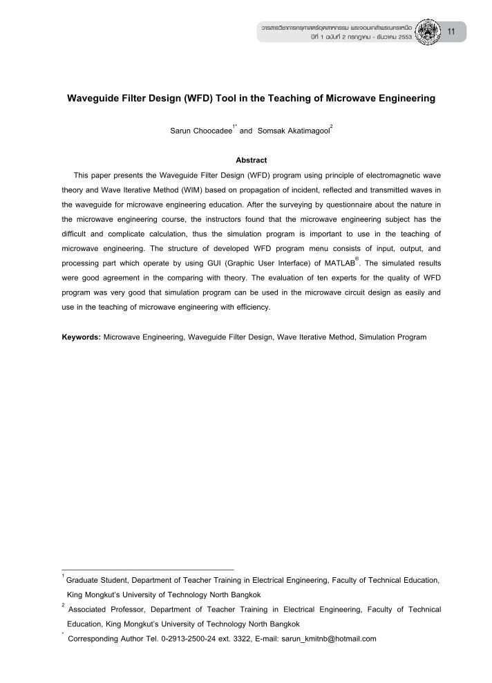
1. Introduction With the technology evolution of MIC’s and microwave applications have come to dominant the global industry. The education, research and development of modern microwave circuits are much stronger influences within the microwave engineering [1-4]. Software tools are indispensable in microwave engineering [1-2], so the researchers and educators rely on simulation program such as Advanced Design System (ADS) by Agilent Technologies (Hewlett Packard), IE3D by Zeland Software and Microwave Office (MWO) by Applied Wave Research. However, most of the microwave circuit simulations cannot be used to design several circuit structure complexity and the students cannot understand the program structure description to edit and develop. Generally, teaching and learning for content of microwave engineering focus to calculate, to analysis and to design the microwave circuits such as microstrip line, planar circuits, filters and waveguide circuits. Microwave engineering is often perceived as highly mathematical and difficult subject to comprehend [3]. After the surveying by using questionnaire and interview of teaching and learning conditions of microwave engineering for 10 instructors and 40 students shown in the figure 1, they found that microwave engineering is the most essential and important subject which can apply to be the radio-frequency ICs or microwave devices. Current teaching of microwave engineering will focus on the facilitating teacher-centered learning. The teaching and learning activities will depend on teachers. Most teaching will be use the teaching media that consists of the textbook, blackboard and Microsoft power point program or transparency sheets.
Figure 1 Learning of microwave engineering course
The microwave education curriculum needs to emphasize are: 1) facilitating student-centered learning model including the efficiency instruction package; 2) simulation program that needs to be used as a critical and efficient tool for microwave education; and 3) instruction media integration such as experiment set and demonstration set which describe the phenomenon of complex content.
In this paper we present the simulation program for waveguide filter design (WFD) that can be used for both research and microwave education. This program can also be used for illustration of the properties of an iris circuit in the waveguide by monitoring the 2.5D electromagnetic wave. All these environments are evaluated from educational viewpoint.2. Wave Iterative Method (WIM)
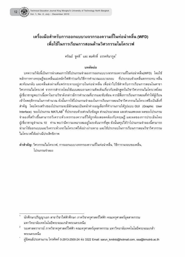
The calculating concept for the electromagnetic wave propagation in the waveguide is based on the Wave Iterative Method (WIM) [5-7]. The process, shown in figure 2, presents the amplitude and direction of the incident, reflected, and transmitted wave which propagate in the waveguide iris circuit. On the iris circuit, the wave is calculated in the real domain (or pixel domain) and the wave in the free space is calculated in the spectrum domain (or
_10-1402(001-040).indd 13 9/4/10 6:42:15 PM
Technical Education Journal King Mongkut’s University of Technology North Bangkok
Vol. 1, No. 2, July - December 2010
��
mode domain). The alternating between both domains, we use the Fast Fourier Transform (FFT) for the fast computation time.
Figure 2 Wave Iterative Method (WIM)
In the figure 2, the first step, the TE10 mode which is the dominant mode propagates into the iris circuit, then the higher order mode of waves caused by the scatter on the conductor surface will incident and reflect within the waveguide. Finally the calculation of waves will use the principle of mode matching at input and output port of waveguide. The initial value of dominant mode is,
02
ixA sin( )
ab a= (1)
The reflected wave ( )iB on the iris circuit is,1( n) (n )
i iB SA= (2) The incident wave ( )iA will though feedback into the waveguide, the equation is,
0(n) (n)i i iA B A+= (3)
Therefore, the relation of incident waves at niteration is,
( )1 10
n(n) (n )i i iA ( S ) A A= + (4)
When a and b are the dimensions of waveguide, n is the number of iteration, i is the number of waveguide port, is the reflection coefficient at input/output port and S is the scattering parameter of iris circuit.
The scattering parameter ( )S of wave in the pixel domain for two ports network can be written as follow,
M D
D M
H HS
H H= (5)
whenMH equal 1 for conductor area and
DH
equal 1 for free space. The reflection coefficient ( ) of wave in spectrum domain (mode) at input and output port of waveguide can be written as the following equation.
0
0
1
1
TETMTE
TMTETM
mnmn
mn
Z Y
Z Y=
+ (6)
when 0Z is the intrinsic Impedance of dominant mode, and mnY is the TE/TM mode admittance in mn order mode.
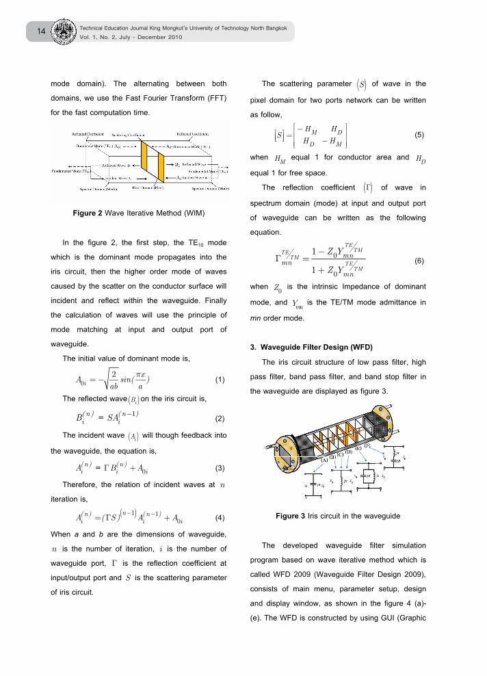
3. Waveguide Filter Design (WFD) The iris circuit structure of low pass filter, high
pass filter, band pass filter, and band stop filter in the waveguide are displayed as figure 3.
Figure 3 Iris circuit in the waveguide
The developed waveguide filter simulation program based on wave iterative method which is called WFD 2009 (Waveguide Filter Design 2009), consists of main menu, parameter setup, design and display window, as shown in the figure 4 (a)-(e). The WFD is constructed by using GUI (Graphic
_10-1402(001-040).indd 14 9/4/10 6:42:16 PM
วารสารวิชาการครุศาสตร์อุตสาหกรรม พระจอมเกล้าพระนครเหนือ
ปีที่ 1 ฉบับที่ 2 กรกฎาคม - ธันวาคม 2553 ��
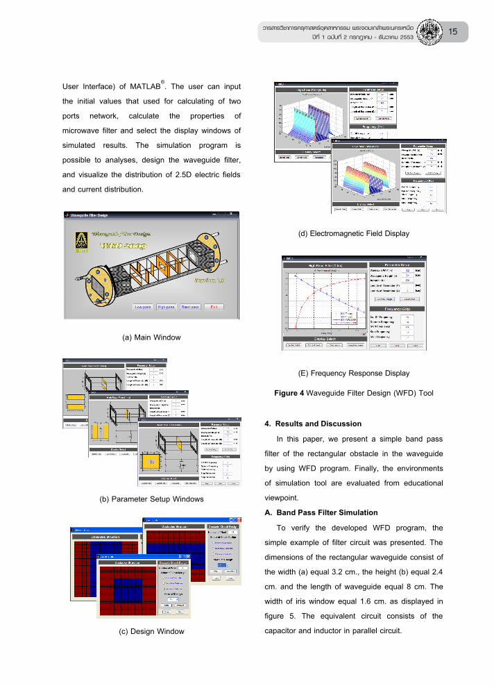
User Interface) of MATLAB®. The user can input the initial values that used for calculating of two ports network, calculate the properties of microwave filter and select the display windows of simulated results. The simulation program is possible to analyses, design the waveguide filter, and visualize the distribution of 2.5D electric fields and current distribution.
(a) Main Window
(b) Parameter Setup Windows
(c) Design Window
(d) Electromagnetic Field Display
(E) Frequency Response Display
Figure 4 Waveguide Filter Design (WFD) Tool
4. Results and Discussion In this paper, we present a simple band pass
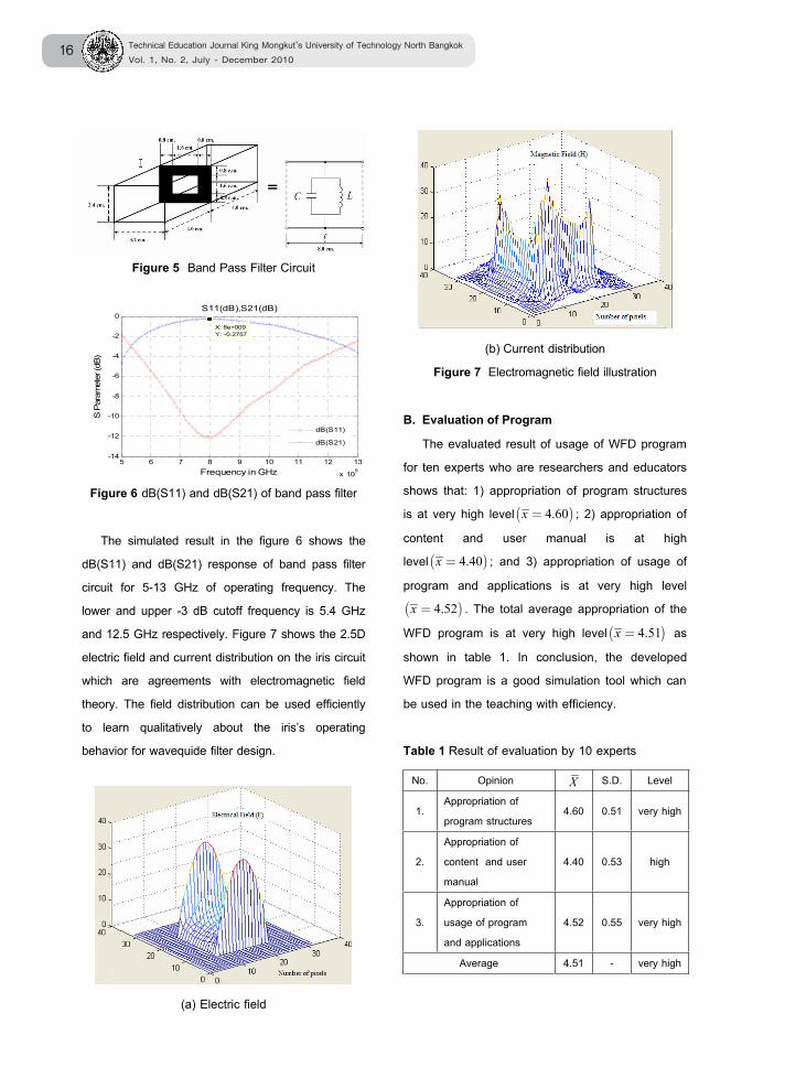
filter of the rectangular obstacle in the waveguide by using WFD program. Finally, the environments of simulation tool are evaluated from educational viewpoint.A. Band Pass Filter Simulation To verify the developed WFD program, the simple example of filter circuit was presented. The dimensions of the rectangular waveguide consist of the width (a) equal 3.2 cm., the height (b) equal 2.4 cm. and the length of waveguide equal 8 cm. The width of iris window equal 1.6 cm. as displayed in figure 5. The equivalent circuit consists of the capacitor and inductor in parallel circuit.
_10-1402(001-040).indd 15 9/4/10 6:42:17 PM
Technical Education Journal King Mongkut’s University of Technology North Bangkok
Vol. 1, No. 2, July - December 2010
��
Figure 5 Band Pass Filter Circuit
5 6 7 8 9 10 11 12 13
x 109
-14
-12
-10
-8
-6
-4
-2
0X: 8e+009Y: -0.2757
S11(dB),S21(dB)
Frequency in GHz
S P
aram
eter
(dB
)
dB(S11)
dB(S21)
Figure 6 dB(S11) and dB(S21) of band pass filter
The simulated result in the figure 6 shows the dB(S11) and dB(S21) response of band pass filter circuit for 5-13 GHz of operating frequency. The lower and upper -3 dB cutoff frequency is 5.4 GHz and 12.5 GHz respectively. Figure 7 shows the 2.5D electric field and current distribution on the iris circuit which are agreements with electromagnetic field theory. The field distribution can be used efficiently to learn qualitatively about the iris’s operating behavior for wavequide filter design.
(a) Electric field
(b) Current distributionFigure 7 Electromagnetic field illustration
B. Evaluation of Program The evaluated result of usage of WFD program for ten experts who are researchers and educators shows that: 1) appropriation of program structures is at very high level( )4.60=x ; 2) appropriation of content and user manual is at high level( )4.40=x ; and 3) appropriation of usage of program and applications is at very high level ( )4.52=x . The total average appropriation of the WFD program is at very high level ( )4.51=x as shown in table 1. In conclusion, the developed WFD program is a good simulation tool which can be used in the teaching with efficiency.
Table 1 Result of evaluation by 10 experts
No. Opinion X S.D. Level
1.Appropriation of program structures
4.60 0.51 very high
2.Appropriation ofcontent and user manual
4.40 0.53 high
3.Appropriation of usage of program and applications
4.52 0.55 very high
Average 4.51 - very high
_10-1402(001-040).indd 16 9/4/10 6:42:18 PM
วารสารวิชาการครุศาสตร์อุตสาหกรรม พระจอมเกล้าพระนครเหนือ
ปีที่ 1 ฉบับที่ 2 กรกฎาคม - ธันวาคม 2553 ��
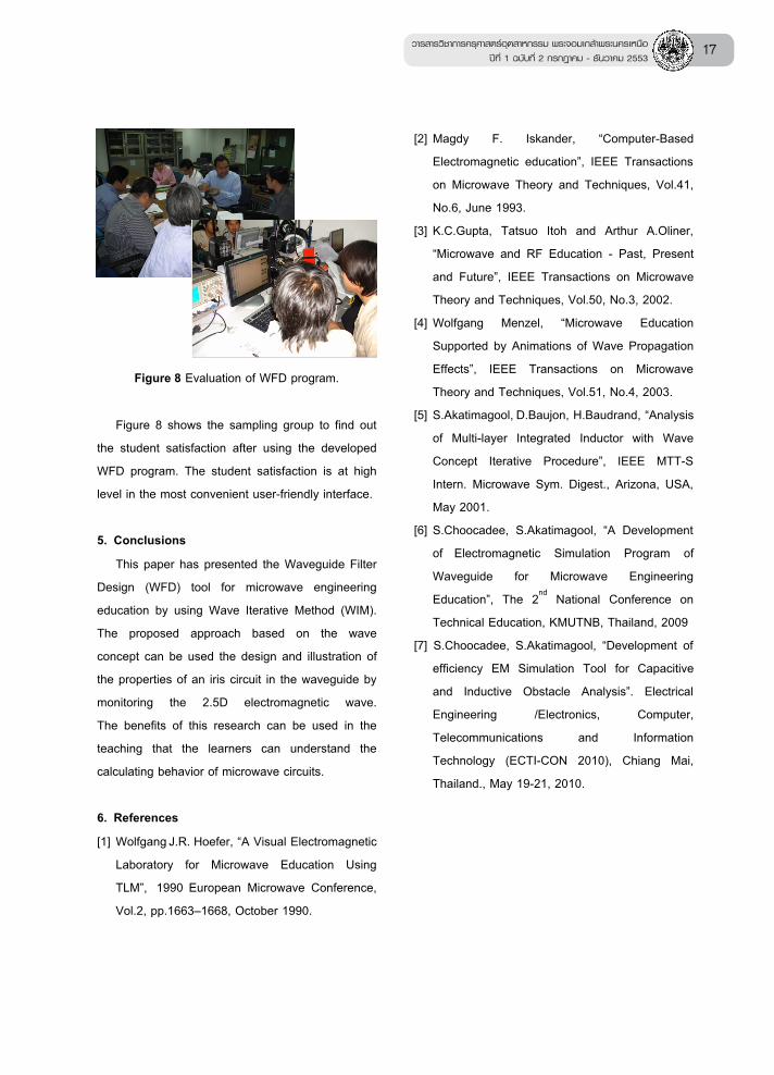
Figure 8 Evaluation of WFD program.
Figure 8 shows the sampling group to find out the student satisfaction after using the developed WFD program. The student satisfaction is at high level in the most convenient user-friendly interface.
5. Conclusions This paper has presented the Waveguide Filter
Design (WFD) tool for microwave engineering education by using Wave Iterative Method (WIM). The proposed approach based on the wave concept can be used the design and illustration of the properties of an iris circuit in the waveguide by monitoring the 2.5D electromagnetic wave. The benefits of this research can be used in the teaching that the learners can understand the calculating behavior of microwave circuits.
6. References [1] Wolfgang J.R. Hoefer, “A Visual Electromagnetic
Laboratory for Microwave Education Using TLM”, 1990 European Microwave Conference,Vol.2, pp.1663–1668, October 1990.
[2] Magdy F. Iskander, “Computer-Based Electromagnetic education”, IEEE Transactions on Microwave Theory and Techniques, Vol.41, No.6, June 1993.
[3] K.C.Gupta, Tatsuo Itoh and Arthur A.Oliner, “Microwave and RF Education - Past, Present and Future”, IEEE Transactions on Microwave Theory and Techniques, Vol.50, No.3, 2002.
[4] Wolfgang Menzel, “Microwave Education Supported by Animations of Wave Propagation Effects”, IEEE Transactions on Microwave Theory and Techniques, Vol.51, No.4, 2003.
[5] S.Akatimagool, D.Baujon, H.Baudrand, “Analysis of Multi-layer Integrated Inductor with Wave Concept Iterative Procedure”, IEEE MTT-S Intern. Microwave Sym. Digest., Arizona, USA, May 2001.
[6] S.Choocadee, S.Akatimagool, “A Development of Electromagnetic Simulation Program of Waveguide for Microwave Engineering Education”, The 2nd National Conference on Technical Education, KMUTNB, Thailand, 2009
[7] S.Choocadee, S.Akatimagool, “Development of efficiency EM Simulation Tool for Capacitive and Inductive Obstacle Analysis”. Electrical Engineering /Electronics, Computer, Telecommunications and Information Technology (ECTI-CON 2010), Chiang Mai, Thailand., May 19-21, 2010.
_10-1402(001-040).indd 17 9/4/10 6:42:18 PM