Embed Size (px)
Citation preview

1 ni.com
3 ni.com
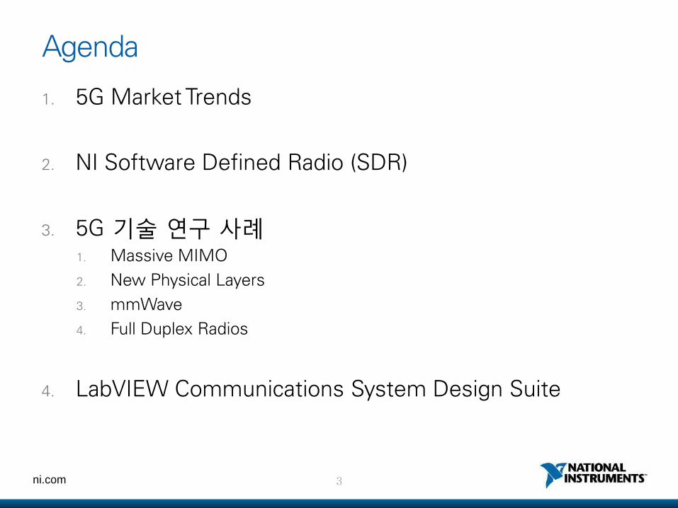
1. 5G Market Trends
2. NI Software Defined Radio (SDR)
3. 5G 기술 연구 사례 1. Massive MIMO
2. New Physical Layers
3. mmWave
4. Full Duplex Radios
4. LabVIEW Communications System Design Suite
Agenda
4 ni.com
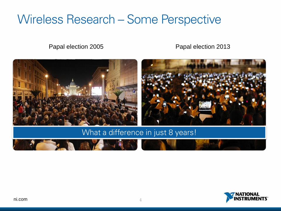
Papal election 2005
Wireless Research – Some Perspective
Papal election 2013
What a difference in just 8 years!
5 ni.com
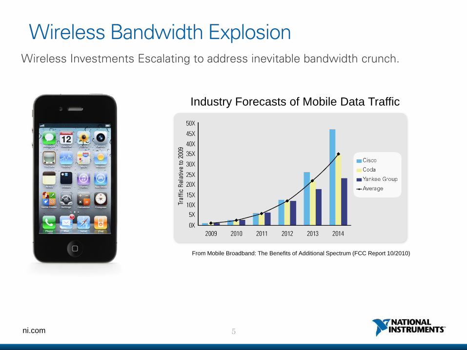
Wireless Bandwidth Explosion
Industry Forecasts of Mobile Data Traffic
From Mobile Broadband: The Benefits of Additional Spectrum (FCC Report 10/2010)
Wireless Investments Escalating to address inevitable bandwidth crunch.
6 ni.com
7 ni.com
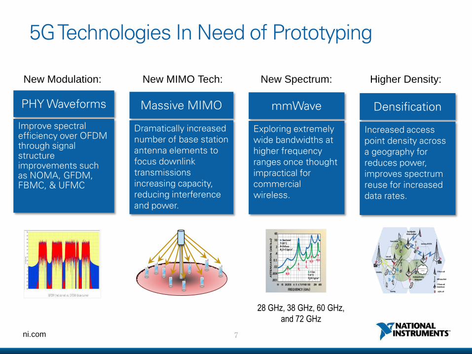
5G Technologies In Need of Prototyping
mmWave
Exploring extremely wide bandwidths at higher frequency ranges once thought impractical for commercial wireless.
New Spectrum:
Massive MIMO
Dramatically increased number of base station antenna elements to focus downlink transmissions increasing capacity, reducing interference and power.
New MIMO Tech:
PHY Waveforms
Improve spectral efficiency over OFDM through signal structure improvements such as NOMA, GFDM, FBMC, & UFMC
New Modulation:
28 GHz, 38 GHz, 60 GHz,
and 72 GHz
Densification
Increased access point density across a geography for reduces power, improves spectrum reuse for increased data rates.
Higher Density:
ni.com
NI Software Defined Radios
9 ni.com
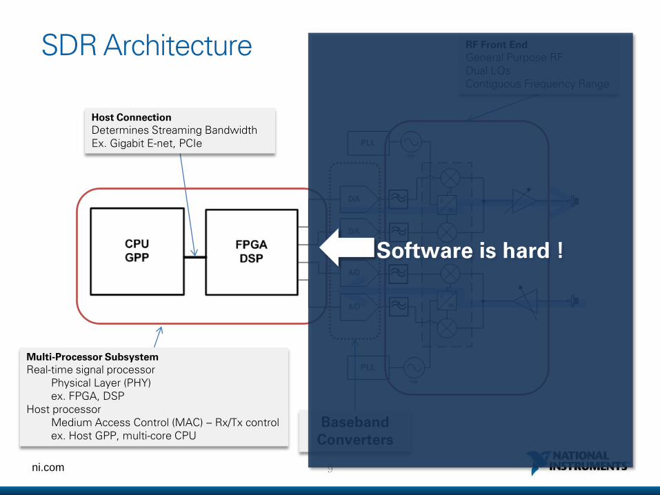
SDR Architecture
Baseband Converters
Host Connection
Determines Streaming Bandwidth Ex. Gigabit E-net, PCIe
Multi-Processor Subsystem
Real-time signal processor Physical Layer (PHY) ex. FPGA, DSP Host processor Medium Access Control (MAC) – Rx/Tx control ex. Host GPP, multi-core CPU
RF Front End
General Purpose RF Dual LOs Contiguous Frequency Range
Software is hard !
10 ni.com
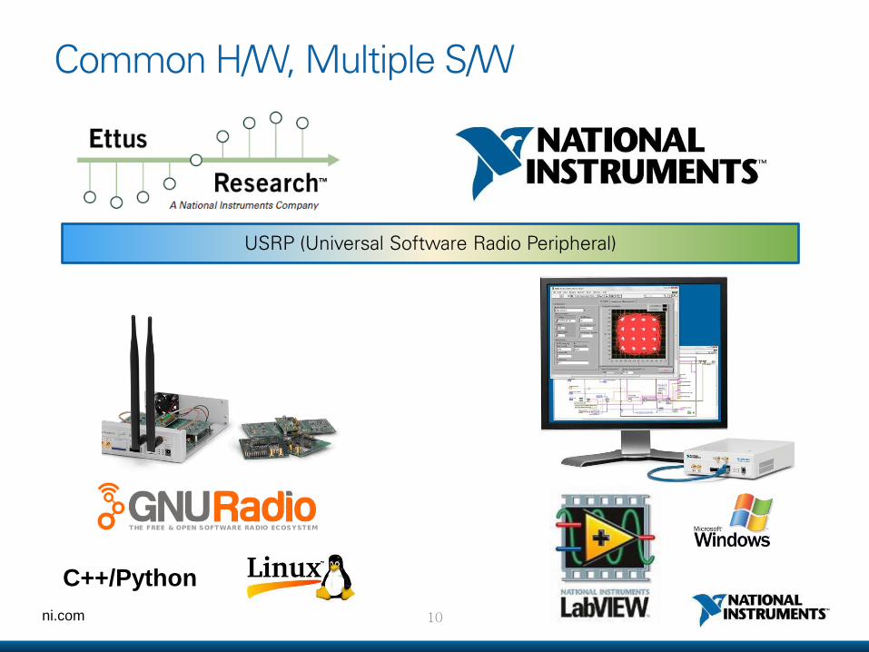
Common H/W, Multiple S/W
C++/Python
USRP (Universal Software Radio Peripheral)
11 ni.com
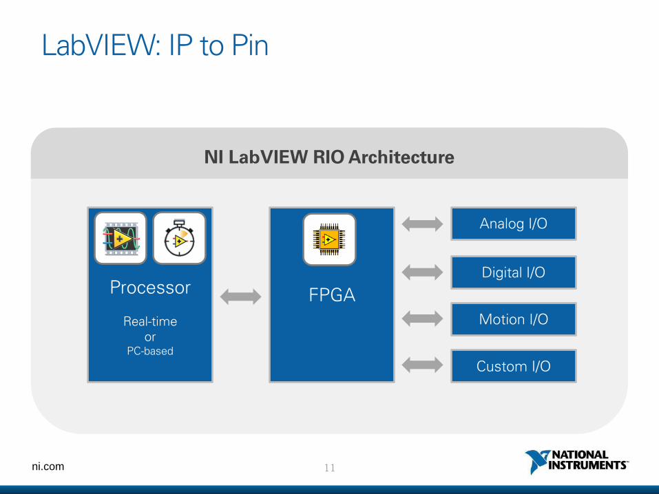
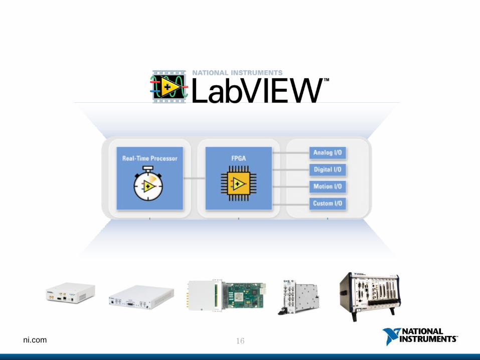
LabVIEW: IP to Pin
NI LabVIEW RIO Architecture
Processor
Real-time or
PC-based
FPGA
Analog I/O
Digital I/O
Motion I/O
Custom I/O
13 ni.com
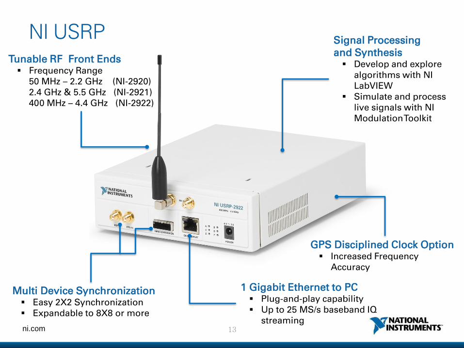
NI USRP
1 Gigabit Ethernet to PC Plug-and-play capability Up to 25 MS/s baseband IQ
streaming
Tunable RF Front Ends Frequency Range
50 MHz – 2.2 GHz (NI-2920) 2.4 GHz & 5.5 GHz (NI-2921) 400 MHz – 4.4 GHz (NI-2922)
Signal Processing and Synthesis Develop and explore
algorithms with NI LabVIEW
Simulate and process live signals with NI Modulation Toolkit
Multi Device Synchronization Easy 2X2 Synchronization Expandable to 8X8 or more
GPS Disciplined Clock Option Increased Frequency
Accuracy
14 ni.com
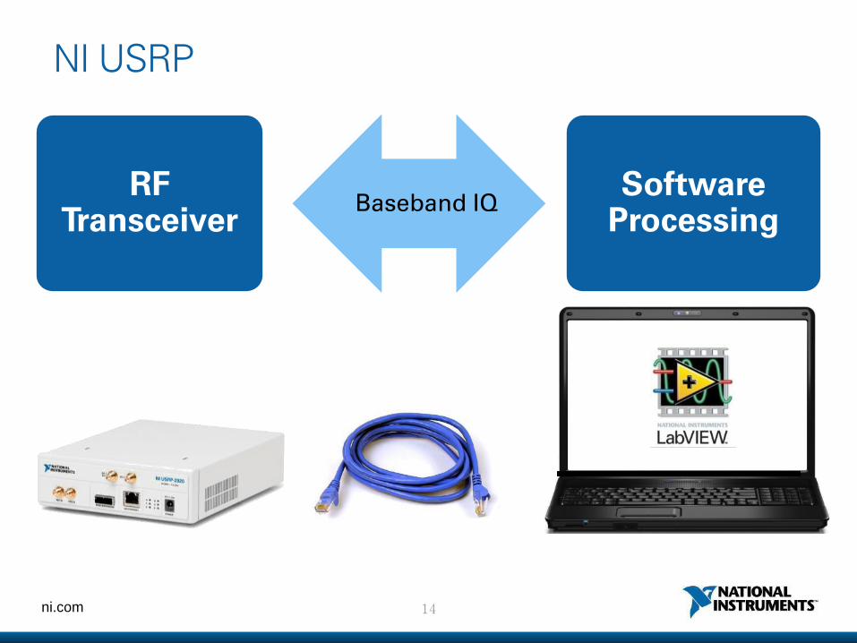
NI USRP
RF Transceiver
Software Processing
Baseband IQ
15 ni.com
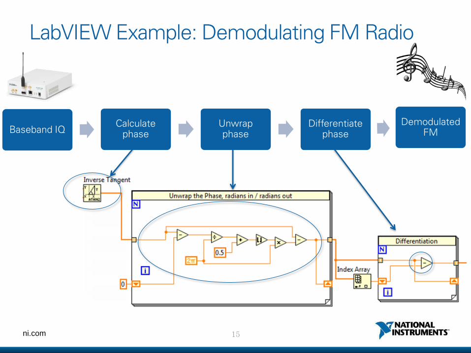
LabVIEW Example: Demodulating FM Radio
Baseband IQ Calculate
phase Unwrap phase
Differentiate phase
Demodulated FM
16 ni.com
17 ni.com
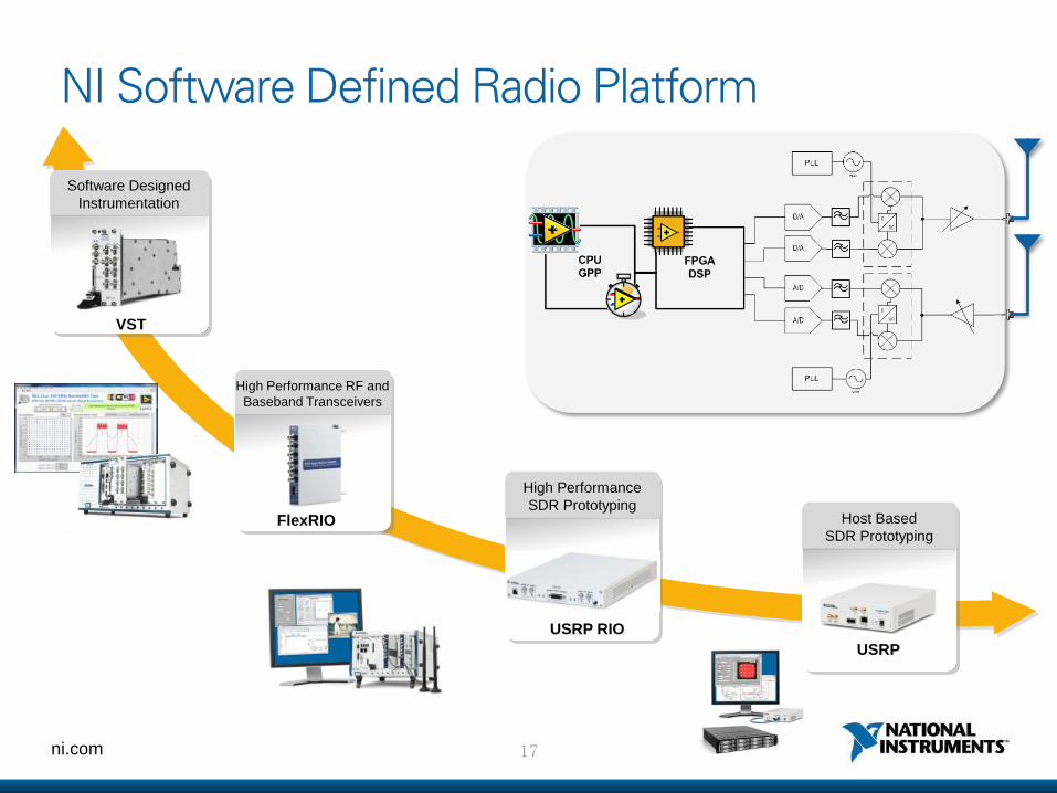
NI Software Defined Radio Platform
Software Designed
Instrumentation
VST
High Performance RF and
Baseband Transceivers
FlexRIO
High Performance
SDR Prototyping
USRP RIO
Host Based
SDR Prototyping
USRP
18 ni.com
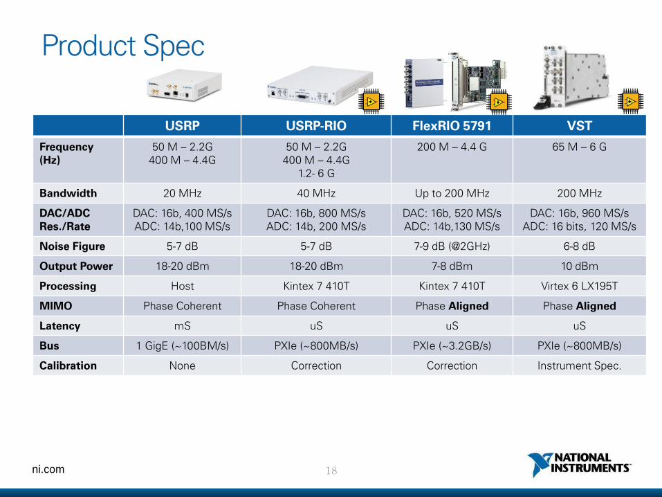
USRP USRP-RIO FlexRIO 5791 VST
Frequency (Hz)
50 M – 2.2G 400 M – 4.4G
50 M – 2.2G 400 M – 4.4G
1.2- 6 G
200 M – 4.4 G 65 M – 6 G
Bandwidth 20 MHz 40 MHz Up to 200 MHz 200 MHz
DAC/ADC Res./Rate
DAC: 16b, 400 MS/s ADC: 14b,100 MS/s
DAC: 16b, 800 MS/s ADC: 14b, 200 MS/s
DAC: 16b, 520 MS/s ADC: 14b,130 MS/s
DAC: 16b, 960 MS/s ADC: 16 bits, 120 MS/s
Noise Figure 5-7 dB 5-7 dB 7-9 dB (@2GHz) 6-8 dB
Output Power 18-20 dBm 18-20 dBm 7-8 dBm 10 dBm
Processing Host Kintex 7 410T Kintex 7 410T Virtex 6 LX195T
MIMO Phase Coherent Phase Coherent Phase Aligned Phase Aligned
Latency mS uS uS uS
Bus 1 GigE (~100BM/s) PXIe (~800MB/s) PXIe (~3.2GB/s) PXIe (~800MB/s)
Calibration None Correction Correction Instrument Spec.
Product Spec
ni.com
5G 기술 연구 사례 1. Massive MIMO
2. New Physical Layers
3. mmWave
4. Full Duplex Radios
ni.com
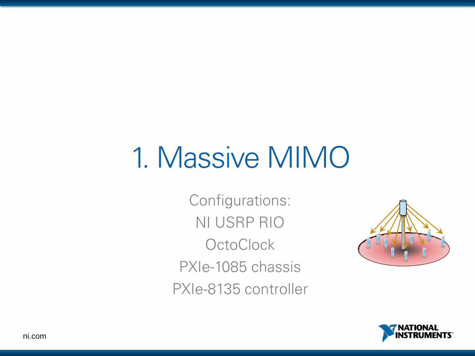
1. Massive MIMO Configurations:
NI USRP RIO
OctoClock
PXIe-1085 chassis
PXIe-8135 controller
21 ni.com
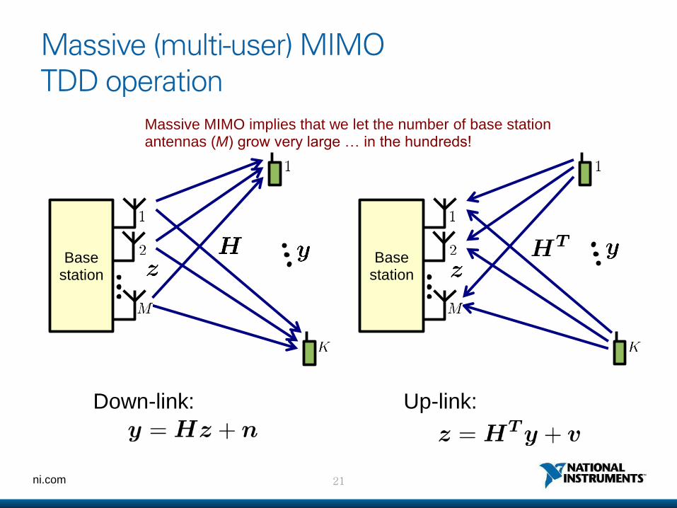
Massive (multi-user) MIMO TDD operation
Base station
Down-link:
Base station
Up-link:
Massive MIMO implies that we let the number of base station antennas (M) grow very large … in the hundreds!
22 ni.com
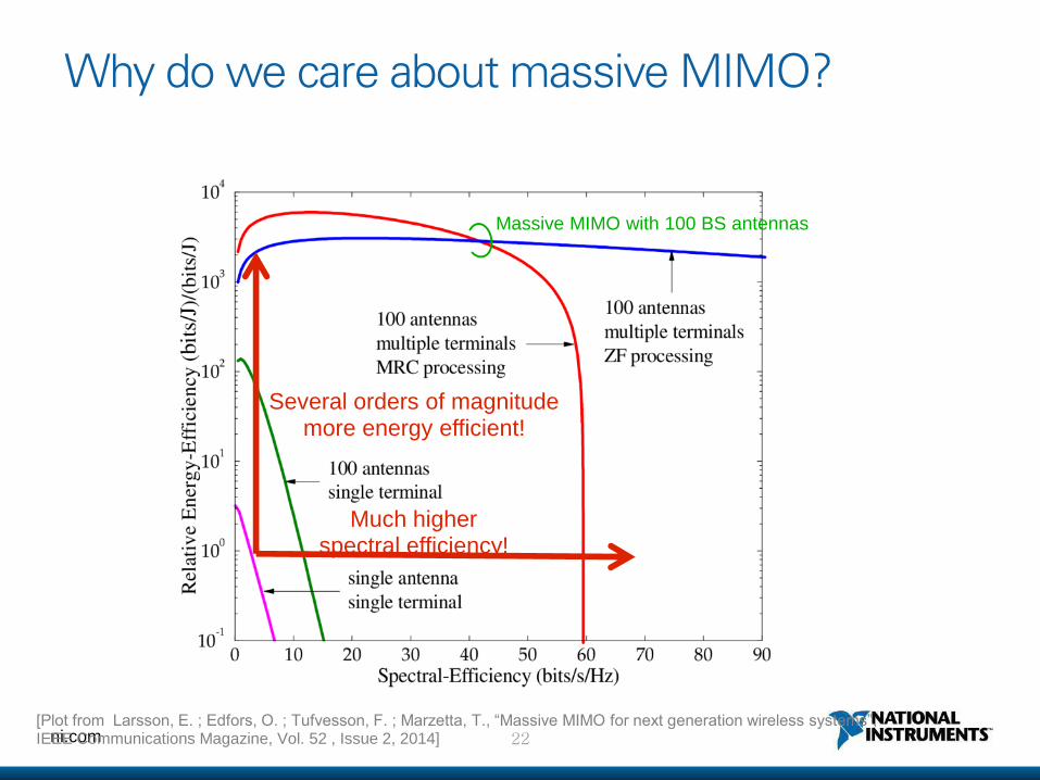
Why do we care about massive MIMO?
Several orders of magnitude more energy efficient!
Much higher spectral efficiency!
Massive MIMO with 100 BS antennas
[Plot from Larsson, E. ; Edfors, O. ; Tufvesson, F. ; Marzetta, T., “Massive MIMO for next generation wireless systems”, IEEE Communications Magazine, Vol. 52 , Issue 2, 2014]
23 ni.com
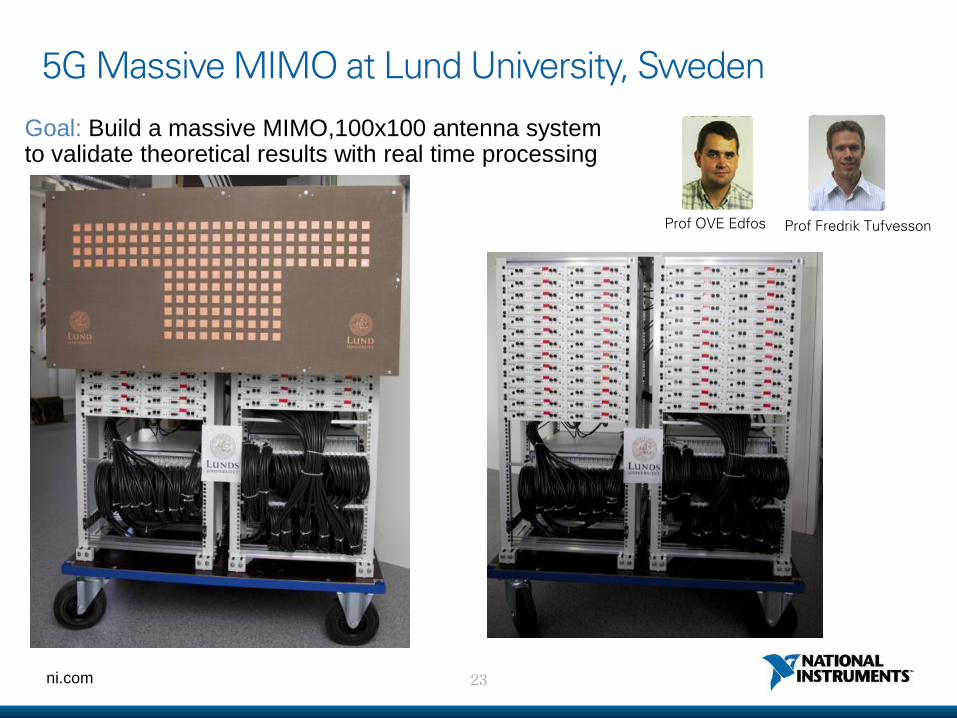
5G Massive MIMO at Lund University, Sweden
Prof OVE Edfos Prof Fredrik Tufvesson
Goal: Build a massive MIMO,100x100 antenna system to validate theoretical results with real time processing
24 ni.com
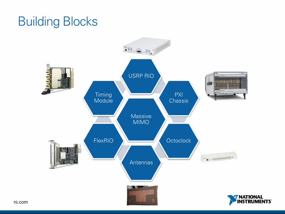
Building Blocks
Massive MIMO
USRP RIO
PXI Chassis
Octoclock
Antennas
FlexRIO
Timing Module
25 ni.com
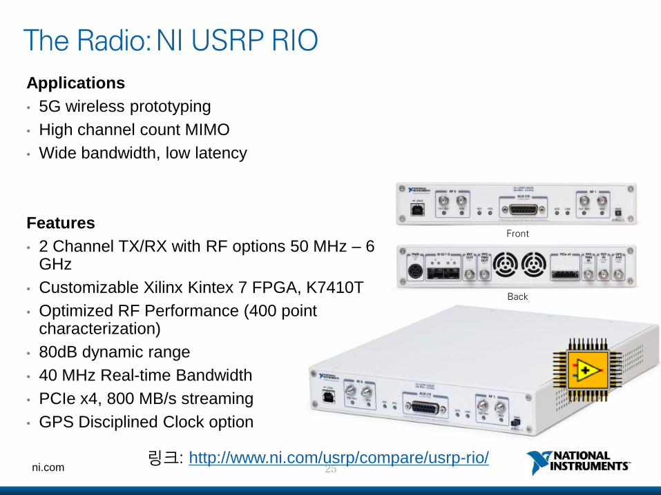
The Radio: NI USRP RIO
Applications
• 5G wireless prototyping
• High channel count MIMO
• Wide bandwidth, low latency
Features
• 2 Channel TX/RX with RF options 50 MHz – 6 GHz
• Customizable Xilinx Kintex 7 FPGA, K7410T
• Optimized RF Performance (400 point characterization)
• 80dB dynamic range
• 40 MHz Real-time Bandwidth
• PCIe x4, 800 MB/s streaming
• GPS Disciplined Clock option
Front
Back
링크: http://www.ni.com/usrp/compare/usrp-rio/
26 ni.com
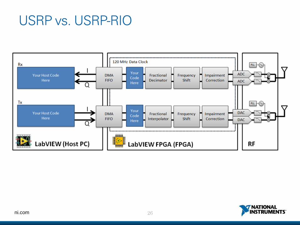
USRP vs. USRP-RIO
27 ni.com
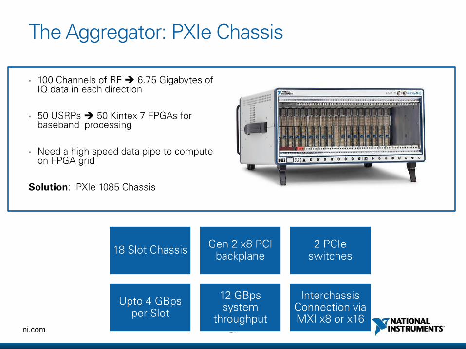
The Aggregator: PXIe Chassis
• 100 Channels of RF 6.75 Gigabytes of IQ data in each direction
• 50 USRPs 50 Kintex 7 FPGAs for baseband processing
• Need a high speed data pipe to compute on FPGA grid
Solution: PXIe 1085 Chassis
18 Slot Chassis Gen 2 x8 PCI
backplane 2 PCIe
switches
Upto 4 GBps per Slot
12 GBps system
throughput
Interchassis Connection via MXI x8 or x16
28 ni.com
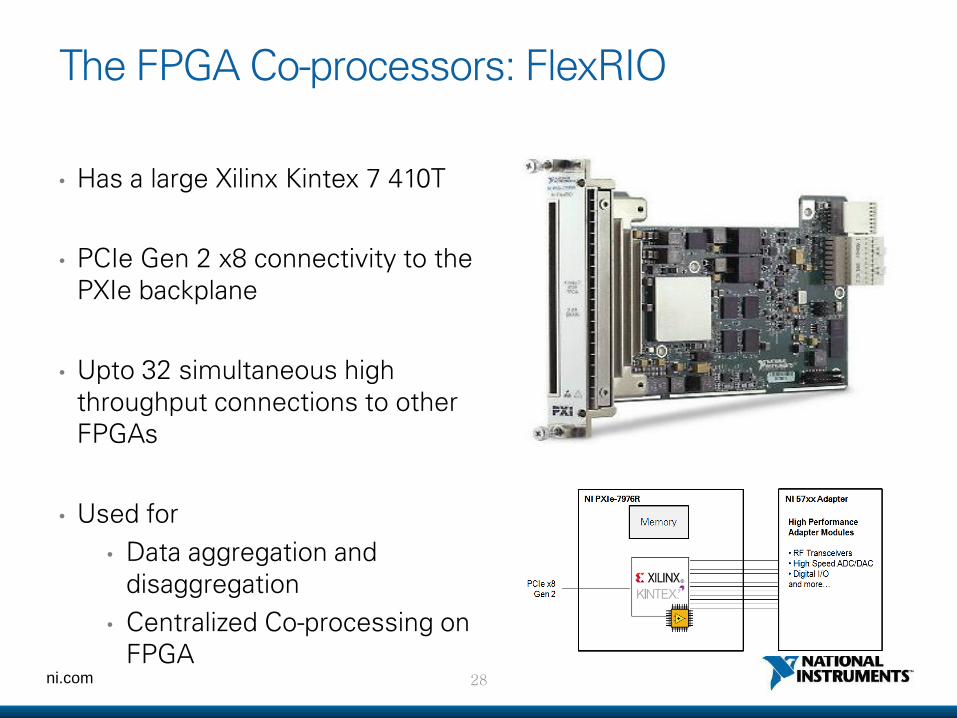
The FPGA Co-processors: FlexRIO
• Has a large Xilinx Kintex 7 410T
• PCIe Gen 2 x8 connectivity to the PXIe backplane
• Upto 32 simultaneous high throughput connections to other FPGAs
• Used for
• Data aggregation and disaggregation
• Centralized Co-processing on FPGA
29 ni.com
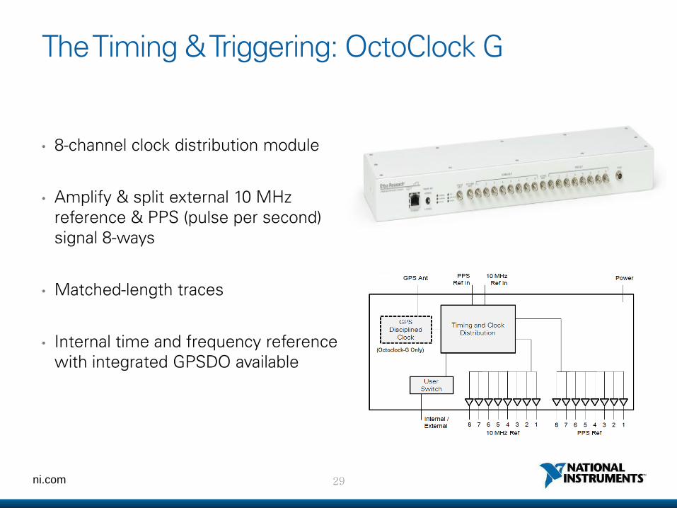
The Timing & Triggering: OctoClock G
• 8-channel clock distribution module
• Amplify & split external 10 MHz reference & PPS (pulse per second) signal 8-ways
• Matched-length traces
• Internal time and frequency reference with integrated GPSDO available
30 ni.com
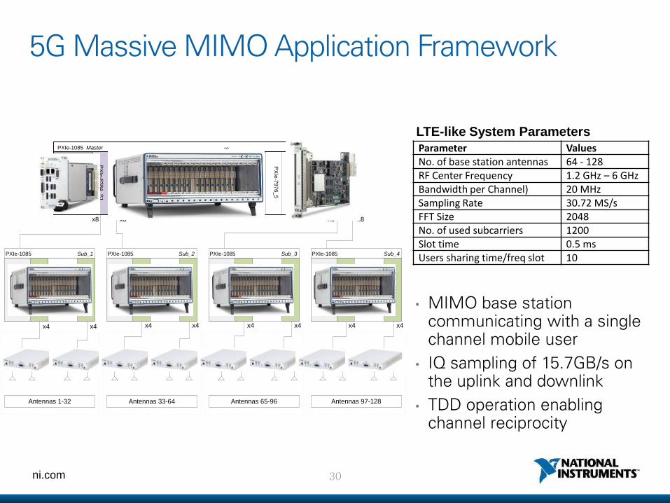
5G Massive MIMO Application Framework
• MIMO base station communicating with a single channel mobile user
• IQ sampling of 15.7GB/s on the uplink and downlink
• TDD operation enabling channel reciprocity
USRP RIO
2x2 (1)
USRP RIO
2x2 (16)
USRP RIO
2x2 (17)
USRP RIO
2x2 (32)
USRP RIO
2x2 (33)
USRP RIO
2x2 (48)
USRP RIO
2x2 (49)
USRP RIO
2x2 (64)
Antennas 1-32 Antennas 33-64 Antennas 65-96 Antennas 97-128
... ... ... ...
PX
Ie-8
38
1
...
PX
Ie-8
26
2_
17
PXIe-1085 Sub_2
PX
Ie-8
26
2_
32
PX
Ie-8
38
1
...
PX
Ie-8
26
2_
49
PXIe-1085 Sub_4
PX
Ie-8
26
2_
64
PX
Ie-8
38
1
...
PX
Ie-8
26
2_
1
PXIe-1085 Sub_1
PX
Ie-8
26
2_
16
PX
Ie-8
38
1
...
PX
Ie-8
26
2_
33
PXIe-1085 Sub_3
PX
Ie-8
26
2_
48
PX
Ie-8
38
4_
S3
PX
Ie-8
38
4_
S4
PX
Ie-7
97
6_
3
PX
Ie-7
97
6_
8
PX
Ie-7
97
6_
5
PX
Ie-7
97
6_
1
PX
Ie-8
38
4_
S1
PX
Ie-8
38
4_
S2
PX
Ie-6
67
4T
PX
Ie-8
13
5
10 18
PX
Ie-7
97
6_
2
PXIe-1085 Master
PX
Ie-7
97
6_
4
PX
eI-7
97
6_
6
PX
Ie-7
97
6_
7
x8 x8 x8 x8
x4 x4 x4 x4 x4 x4 x4 x4
Parameter Values No. of base station antennas 64 - 128 RF Center Frequency 1.2 GHz – 6 GHz Bandwidth per Channel) 20 MHz Sampling Rate 30.72 MS/s FFT Size 2048 No. of used subcarriers 1200 Slot time 0.5 ms Users sharing time/freq slot 10
LTE-like System Parameters
31 ni.com
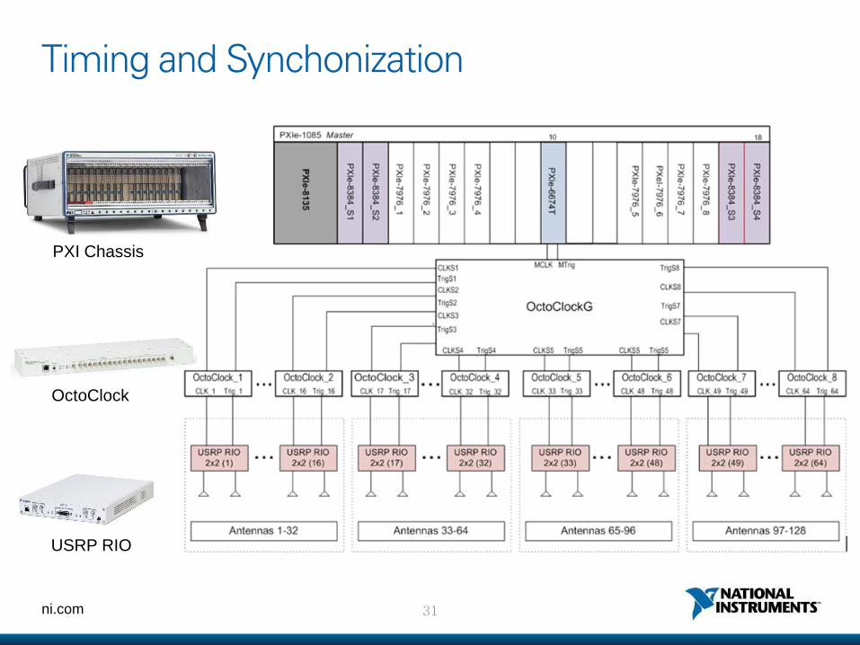
Timing and Synchonization
USRP RIO
OctoClock
PXI Chassis
32 ni.com
Demo 영상
https://www.youtube.com/watch?v=e3nVGIplXjk
ni.com
2. New Physical Layers Configurations:
FlexRIO FPGA module
FlexRIO 5791 module
PXIe-1085 chassis
PXIe-8135 controller
34 ni.com
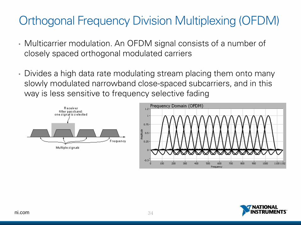
Orthogonal Frequency Division Multiplexing (OFDM)
• Multicarrier modulation. An OFDM signal consists of a number of closely spaced orthogonal modulated carriers
• Divides a high data rate modulating stream placing them onto many slowly modulated narrowband close-spaced subcarriers, and in this way is less sensitive to frequency selective fading
35 ni.com
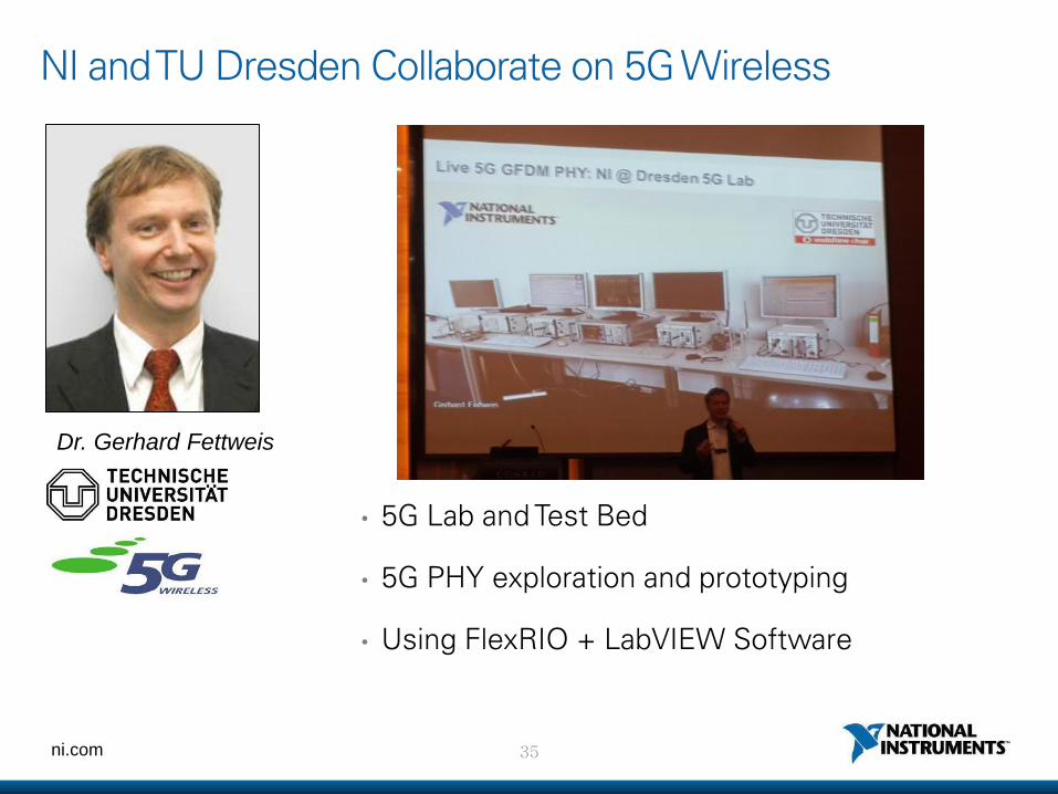
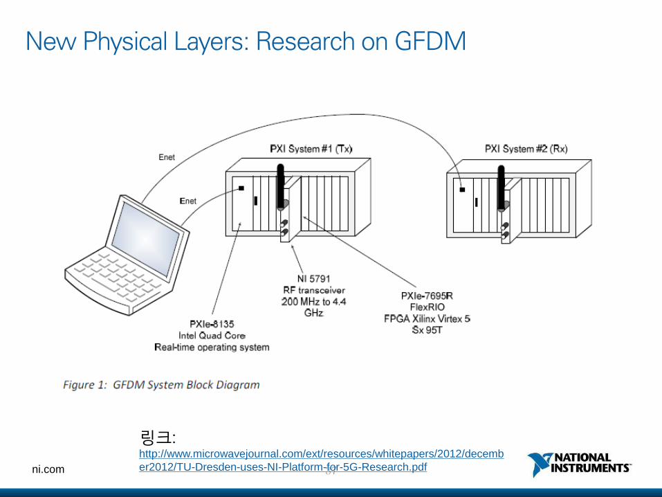
NI and TU Dresden Collaborate on 5G Wireless
• 5G Lab and Test Bed
• 5G PHY exploration and prototyping
• Using FlexRIO + LabVIEW Software
Dr. Gerhard Fettweis
36 ni.com
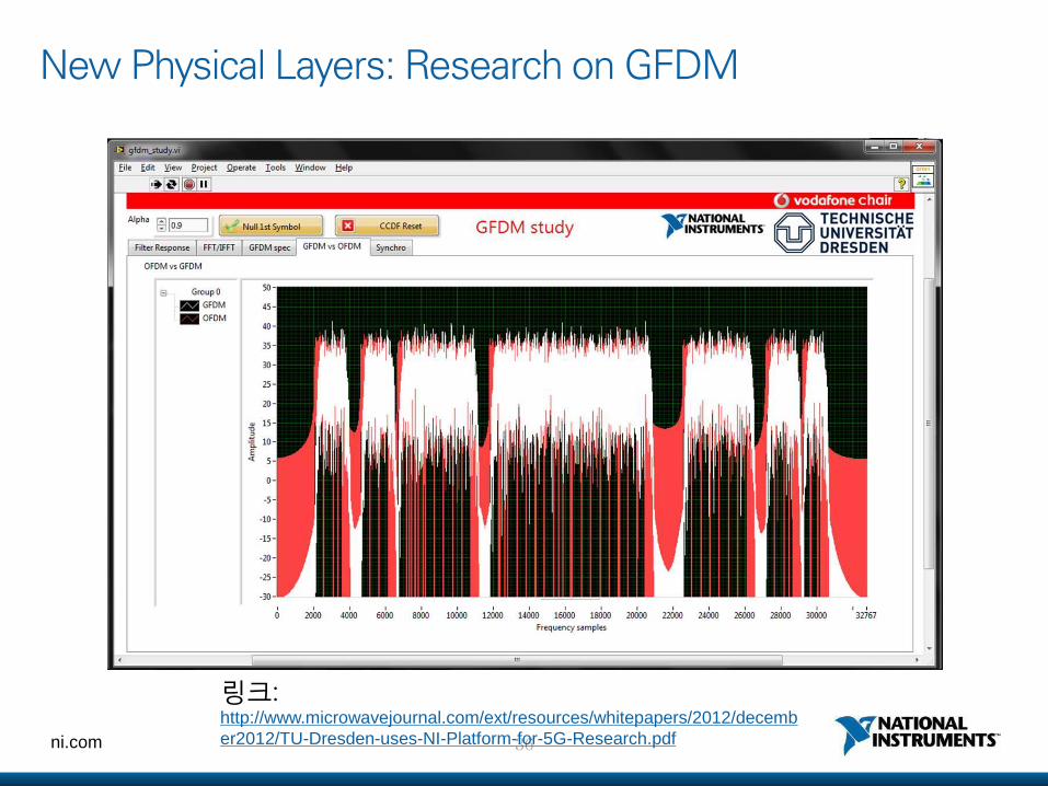
New Physical Layers: Research on GFDM
링크: http://www.microwavejournal.com/ext/resources/whitepapers/2012/decemb
er2012/TU-Dresden-uses-NI-Platform-for-5G-Research.pdf
37 ni.com
New Physical Layers: Research on GFDM
링크: http://www.microwavejournal.com/ext/resources/whitepapers/2012/decemb
er2012/TU-Dresden-uses-NI-Platform-for-5G-Research.pdf
38 ni.com
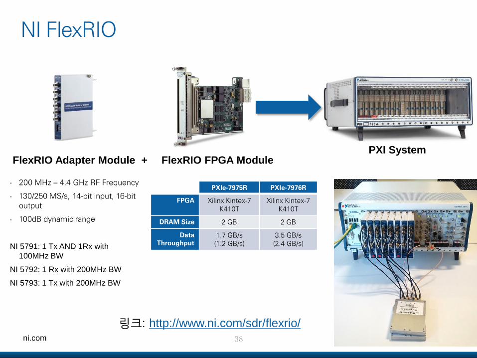
NI FlexRIO
PXI System
• 200 MHz – 4.4 GHz RF Frequency
• 130/250 MS/s, 14-bit input, 16-bit output
• 100dB dynamic range
NI 5791: 1 Tx AND 1Rx with
100MHz BW
NI 5792: 1 Rx with 200MHz BW
NI 5793: 1 Tx with 200MHz BW
FlexRIO Adapter Module + FlexRIO FPGA Module
PXIe-7975R PXIe-7976R
FPGA Xilinx Kintex-7 K410T
Xilinx Kintex-7 K410T
DRAM Size 2 GB 2 GB
Data Throughput
1.7 GB/s (1.2 GB/s)
3.5 GB/s (2.4 GB/s)
링크: http://www.ni.com/sdr/flexrio/
ni.com
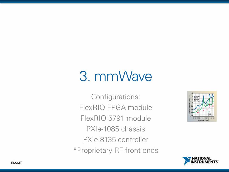
3. mmWave
Configurations:
FlexRIO FPGA module
FlexRIO 5791 module
PXIe-1085 chassis
PXIe-8135 controller
*Proprietary RF front ends
40 ni.com
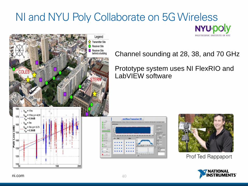
NI and NYU Poly Collaborate on 5G Wireless
Prof Ted Rappaport
Channel sounding at 28, 38, and 70 GHz
Prototype system uses NI FlexRIO and LabVIEW software
41 ni.com
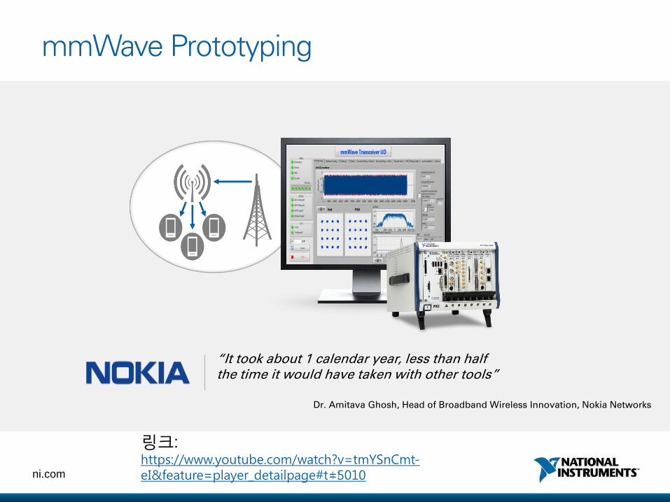
mmWave Prototyping
“It took about 1 calendar year, less than half the time it would have taken with other tools”
Dr. Amitava Ghosh, Head of Broadband Wireless Innovation, Nokia Networks
링크: https://www.youtube.com/watch?v=tmYSnCmt-eI&feature=player_detailpage#t=5010
42 ni.com
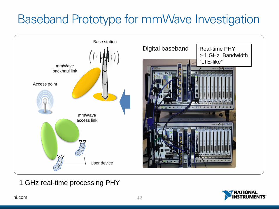
Baseband Prototype for mmWave Investigation
Real-time PHY
> 1 GHz Bandwidth
“LTE-like”
Digital baseband
mmWave
access link
mmWave
backhaul link
Base station
User device
Access point
1 GHz real-time processing PHY
43 ni.com
Demo
http://networks.nokia.com/videos/ntt-docomo-5g-collaboration
ni.com
4. Full Duplex Radios
Configurations:
FlexRIO FPGA module
FlexRIO 5791 module
PXIe-1085 chassis
PXIe-8135 controller
45 ni.com
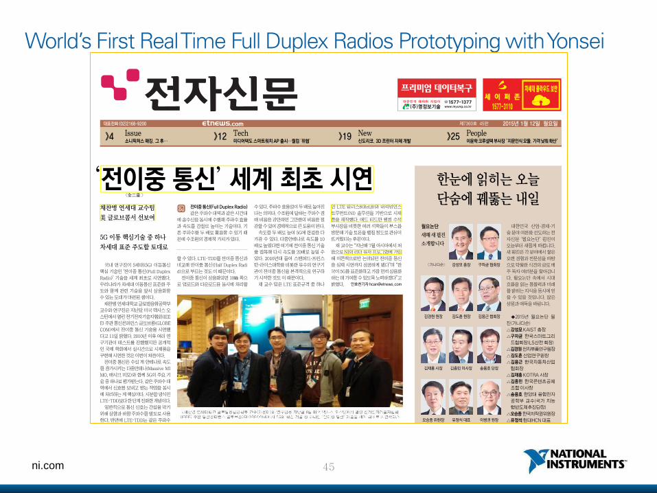
World’s First Real Time Full Duplex Radios Prototyping with Yonsei
46 ni.com
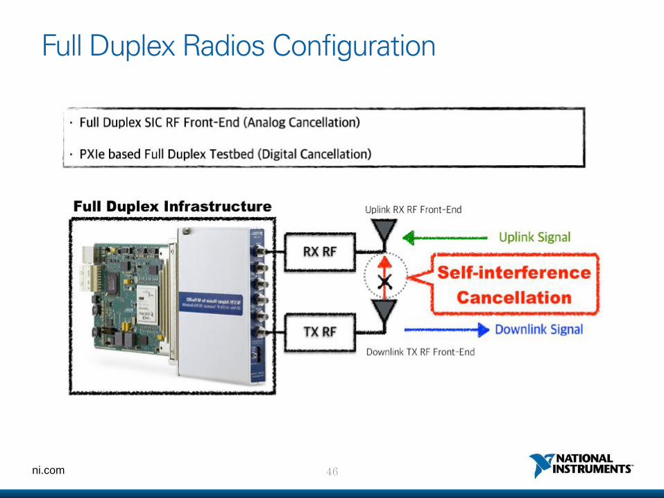
Full Duplex Radios Configuration
47 ni.com
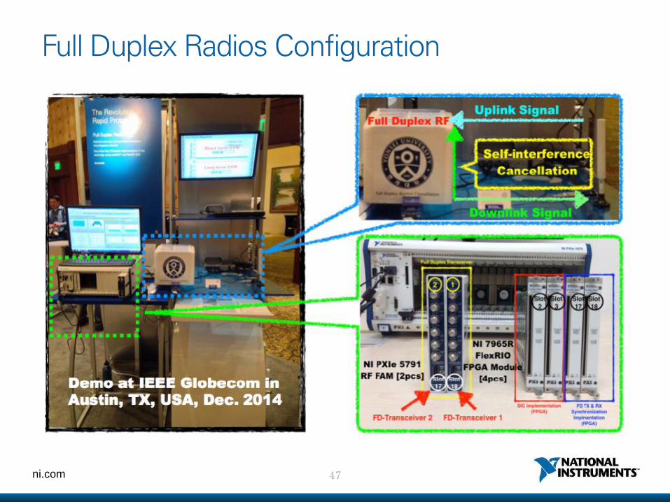
Full Duplex Radios Configuration
48 ni.com
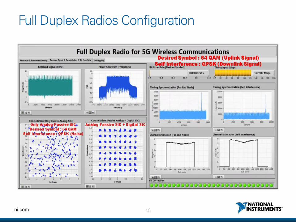
Full Duplex Radios Configuration
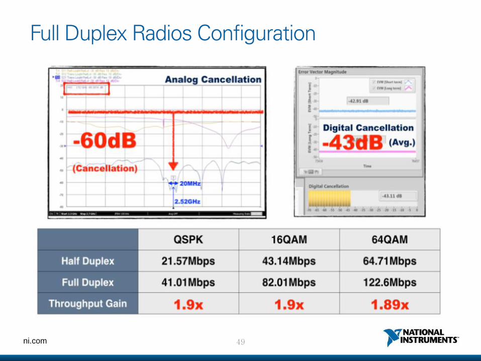
49 ni.com
Full Duplex Radios Configuration
50 ni.com
Demo 영상
https://www.youtube.com/watch?v=WzYwIfOSEy8&feature=player_detailpage
ni.com
LabVIEW Communications Design Suite
52 ni.com
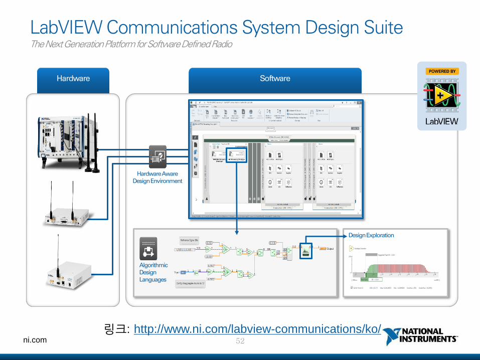
LabVIEW Communications System Design Suite The Next Generation Platform for Software Defined Radio
Hardware Software
Hardware Aware Design Environment
Algorithmic Design Languages
Design Exploration
링크: http://www.ni.com/labview-communications/ko/
53 ni.com
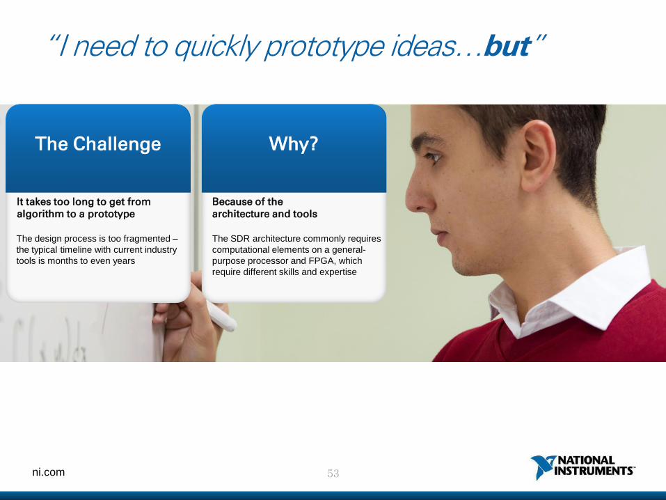
“I need to quickly prototype ideas…but”
The Challenge
The design process is too fragmented –
the typical timeline with current industry
tools is months to even years
Why?
The SDR architecture commonly requires
computational elements on a general-
purpose processor and FPGA, which
require different skills and expertise
It takes too long to get from algorithm to a prototype
Because of the architecture and tools
54 ni.com
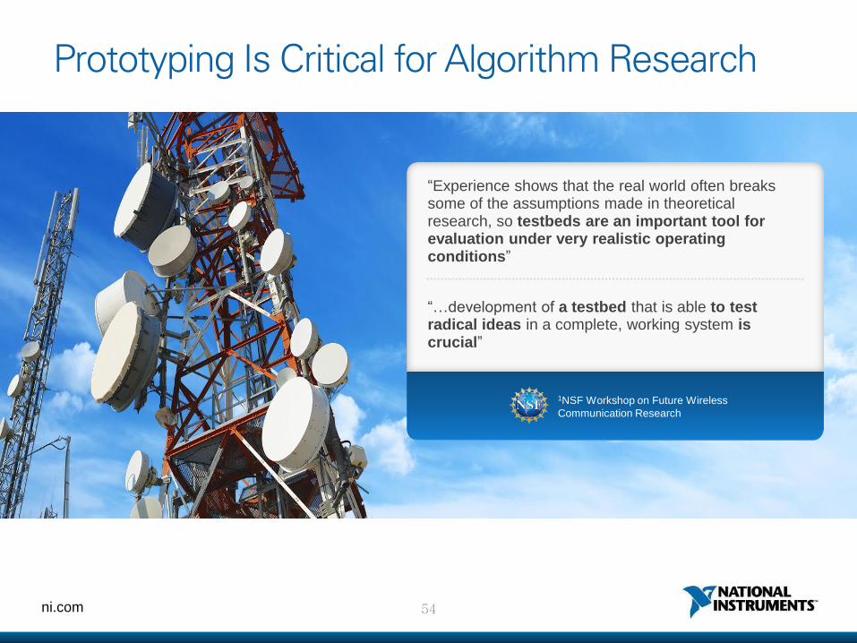
Prototyping Is Critical for Algorithm Research
“Experience shows that the real world often breaks some of the assumptions made in theoretical research, so testbeds are an important tool for evaluation under very realistic operating conditions”
“…development of a testbed that is able to test radical ideas in a complete, working system is crucial”
1NSF Workshop on Future Wireless
Communication Research
55 ni.com
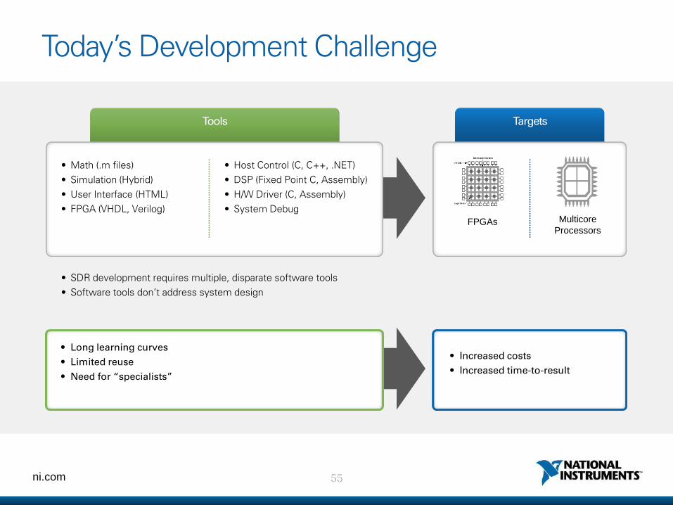
Today’s Development Challenge
• SDR development requires multiple, disparate software tools
• Software tools don’t address system design
Tools
• Math (.m files)
• Simulation (Hybrid)
• User Interface (HTML)
• FPGA (VHDL, Verilog)
• Host Control (C, C++, .NET)
• DSP (Fixed Point C, Assembly)
• H/W Driver (C, Assembly)
• System Debug
• Long learning curves
• Limited reuse
• Need for “specialists”
• Increased costs
• Increased time-to-result
Targets
FPGAs Multicore
Processors
56 ni.com
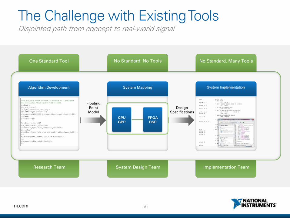
The Challenge with Existing Tools Disjointed path from concept to real-world signal
One Standard Tool
System Mapping System Implementation Algorithm Development
System Design Team
Floating Point Model
Design Specifications
No Standard. No Tools No Standard. Many Tools
Research Team Implementation Team
CPU
GPP
FPGA
DSP
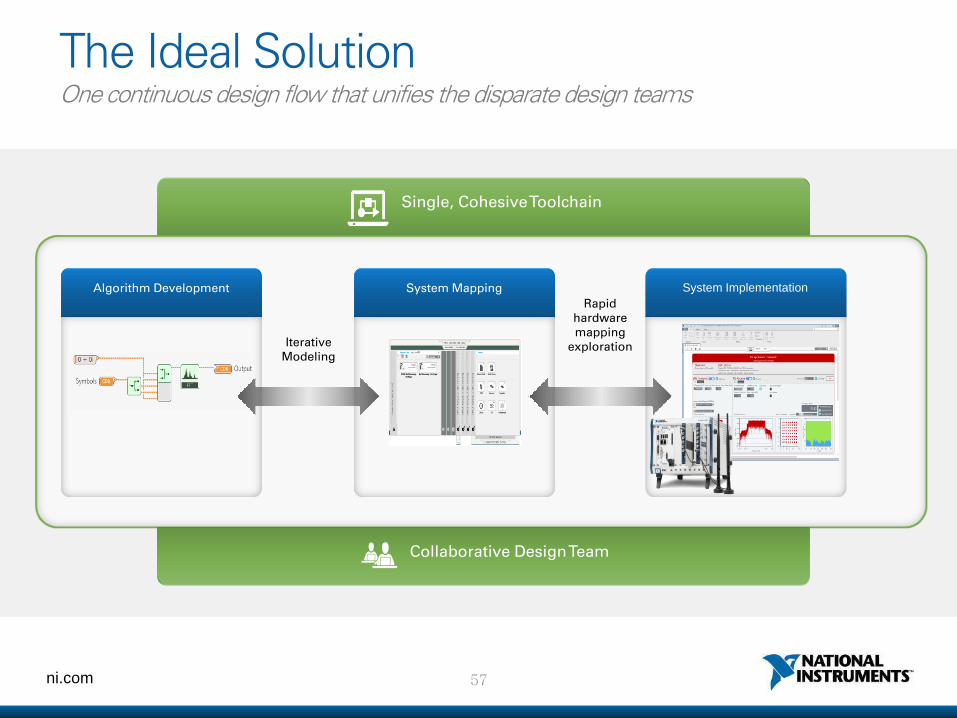
57 ni.com
The Ideal Solution One continuous design flow that unifies the disparate design teams
Single, Cohesive Toolchain
System Mapping System Implementation Algorithm Development
Collaborative Design Team
Iterative Modeling
Rapid hardware mapping
exploration
58 ni.com
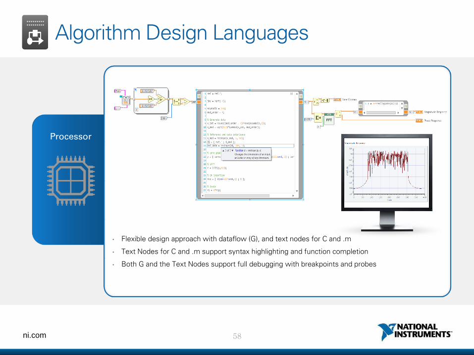
Processor
Algorithm Design Languages
• Flexible design approach with dataflow (G), and text nodes for C and .m
• Text Nodes for C and .m support syntax highlighting and function completion
• Both G and the Text Nodes support full debugging with breakpoints and probes
59 ni.com
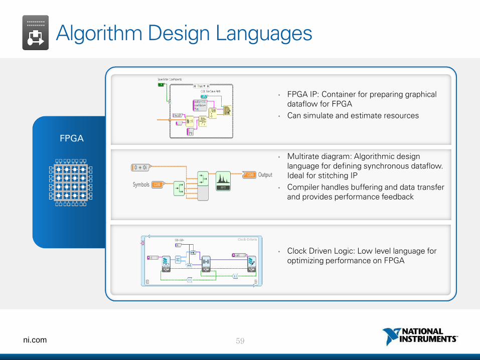
FPGA
Algorithm Design Languages
• Multirate diagram: Algorithmic design language for defining synchronous dataflow. Ideal for stitching IP
• Compiler handles buffering and data transfer and provides performance feedback
• FPGA IP: Container for preparing graphical dataflow for FPGA
• Can simulate and estimate resources
• Clock Driven Logic: Low level language for optimizing performance on FPGA
60 ni.com
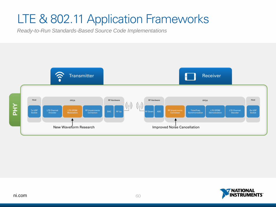
LTE & 802.11 Application Frameworks P
HY
Ready-to-Run Standards-Based Source Code Implementations
Transmitter Receiver
Host FPGA RF Hardware
RF Up DAC RF Impairments
Correction LTE OFDM Modulation
LTE Channel Encoder
Tx UDP Socket
RF Hardware
RF Down ADC
FPGA
RF Impairments Correction
Time/Freq. Synchronization
LTE OFDM Demodulation
LTE Channel Decoder
Host
Rx UDP Socket
Improved Noise Cancellation New Waveform Research
61 ni.com
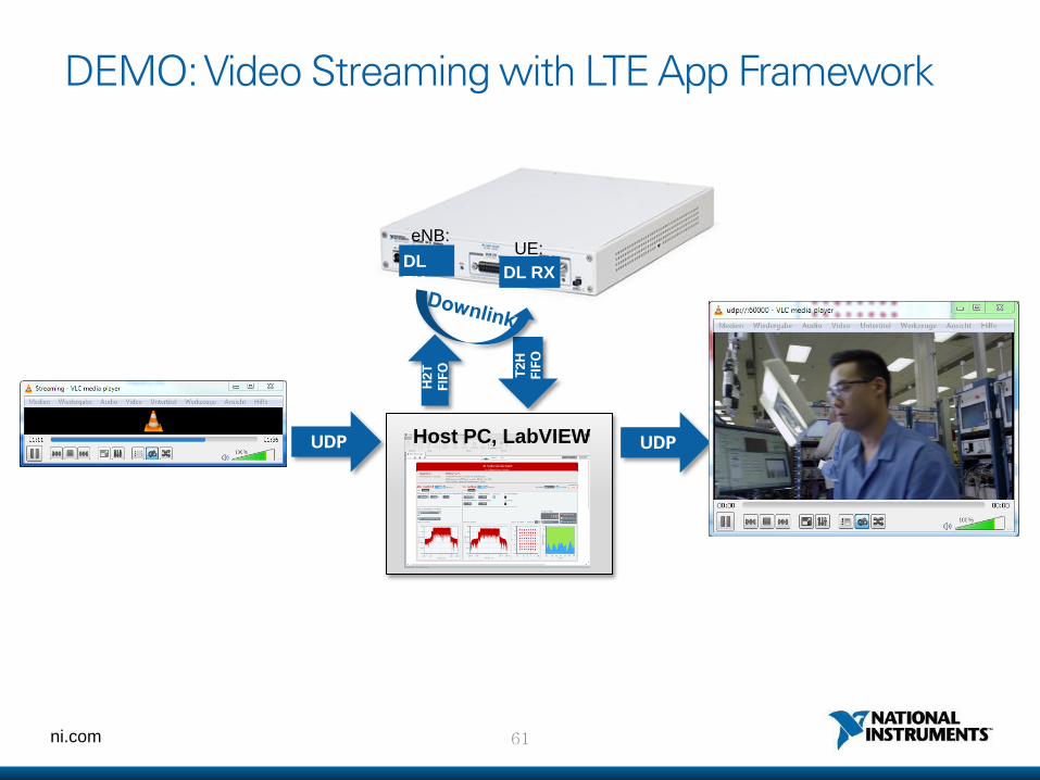
DEMO: Video Streaming with LTE App Framework
H2
T
FIF
O
T2
H
FIF
O
UDP UDP
Host PC
Host PC, LabVIEW
DL RX
UE: DL
TX
eNB:

62 ni.com
LabVIEW Communications System Design Suite The Next Generation Platform for Software Defined Radio
Hardware Software
Hardware Aware Design Environment
Algorithmic Design Languages
Design Exploration
링크: http://www.ni.com/labview-communications/ko/
63 ni.com
Try LabVIEW Communications
Download and evaluate at
ni.com/labviewcomms/try
64 ni.com
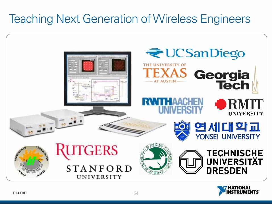
Teaching Next Generation of Wireless Engineers
65 ni.com
5G 이동통신 연구원분들을 응원합니다!
66 ni.com