Embed Size (px)
Citation preview
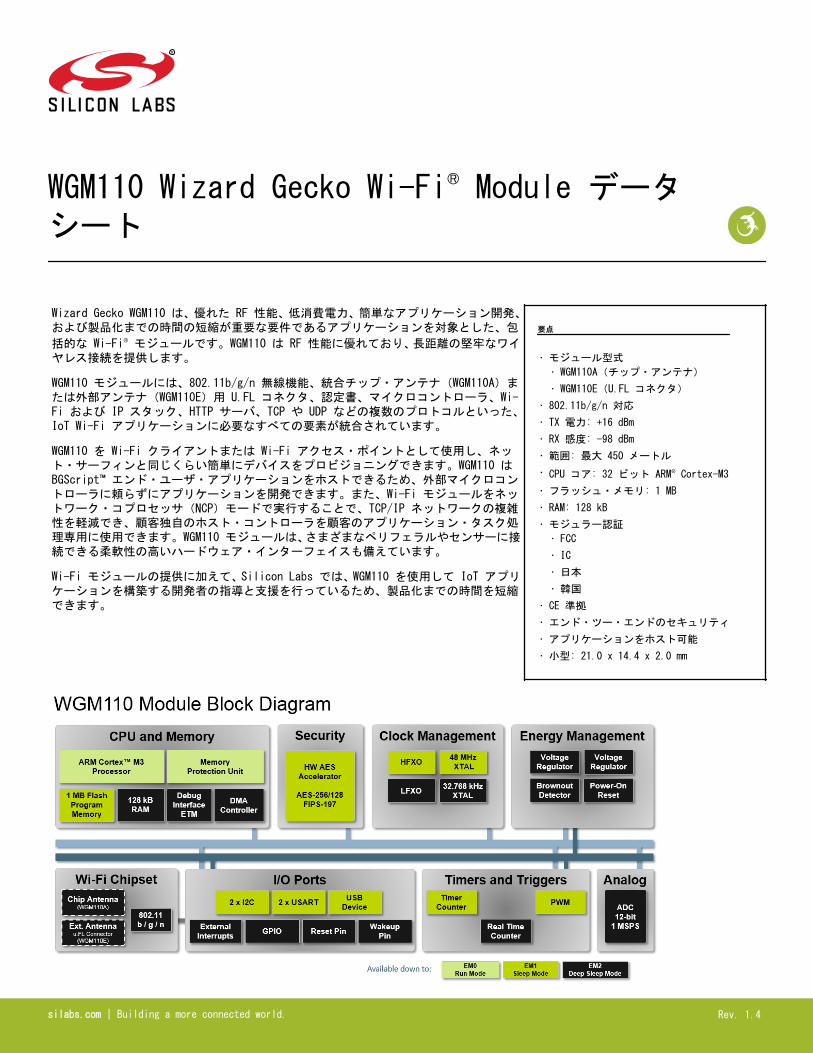
WGM110 Wizard Gecko Wi-Fi® Module データシート
Wizard Gecko WGM110 は、優れた RF 性能、低消費電力、簡単なアプリケーション開発、および製品化までの時間の短縮が重要な要件であるアプリケーションを対象とした、包
括的な Wi-Fi® モジュールです。WGM110 は RF 性能に優れており、長距離の堅牢なワイヤレス接続を提供します。
WGM110 モジュールには、802.11b/g/n 無線機能、統合チップ・アンテナ(WGM110A)または外部アンテナ(WGM110E)用 U.FL コネクタ、認定書、マイクロコントローラ、Wi-Fi および IP スタック、HTTP サーバ、TCP や UDP などの複数のプロトコルといった、IoT Wi-Fi アプリケーションに必要なすべての要素が統合されています。
WGM110 を Wi-Fi クライアントまたは Wi-Fi アクセス・ポイントとして使用し、ネット・サーフィンと同じくらい簡単にデバイスをプロビジョニングできます。WGM110 はBGScript™ エンド・ユーザ・アプリケーションをホストできるため、外部マイクロコントローラに頼らずにアプリケーションを開発できます。また、Wi-Fi モジュールをネットワーク・コプロセッサ(NCP)モードで実行することで、TCP/IP ネットワークの複雑性を軽減でき、顧客独自のホスト・コントローラを顧客のアプリケーション・タスク処理専用に使用できます。WGM110 モジュールは、さまざまなペリフェラルやセンサーに接続できる柔軟性の高いハードウェア・インターフェイスも備えています。
Wi-Fi モジュールの提供に加えて、Silicon Labs では、WGM110 を使用して IoT アプリケーションを構築する開発者の指導と支援を行っているため、製品化までの時間を短縮できます。
要点
• モジュール型式
• WGM110A(チップ・アンテナ)
• WGM110E(U.FL コネクタ)
• 802.11b/g/n 対応
• TX 電力: +16 dBm
• RX 感度: -98 dBm
• 範囲: 最大 450 メートル
• CPU コア: 32 ビット ARM® Cortex-M3
• フラッシュ・メモリ: 1 MB
• RAM: 128 kB
• モジュラー認証
• FCC
• IC
• 日本
• 韓国
• CE 準拠
• エンド・ツー・エンドのセキュリティ
• アプリケーションをホスト可能
• 小型: 21.0 x 14.4 x 2.0 mm
silabs.com | Building a more connected world. Rev. 1.4
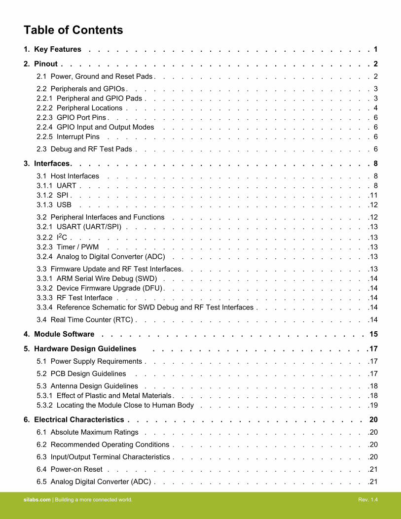
Table of Contents1. Key Features . . . . . . . . . . . . . . . . . . . . . . . . . . . . . . . 1
2. Pinout . . . . . . . . . . . . . . . . . . . . . . . . . . . . . . . . . . 22.1 Power, Ground and Reset Pads . . . . . . . . . . . . . . . . . . . . . . . . 2
2.2 Peripherals and GPIOs . . . . . . . . . . . . . . . . . . . . . . . . . . . 32.2.1 Peripheral and GPIO Pads . . . . . . . . . . . . . . . . . . . . . . . . . 32.2.2 Peripheral Locations . . . . . . . . . . . . . . . . . . . . . . . . . . . 42.2.3 GPIO Port Pins . . . . . . . . . . . . . . . . . . . . . . . . . . . . . 62.2.4 GPIO Input and Output Modes . . . . . . . . . . . . . . . . . . . . . . . 62.2.5 Interrupt Pins . . . . . . . . . . . . . . . . . . . . . . . . . . . . . 6
2.3 Debug and RF Test Pads . . . . . . . . . . . . . . . . . . . . . . . . . . 6
3. Interfaces. . . . . . . . . . . . . . . . . . . . . . . . . . . . . . . . . 83.1 Host Interfaces . . . . . . . . . . . . . . . . . . . . . . . . . . . . . 83.1.1 UART . . . . . . . . . . . . . . . . . . . . . . . . . . . . . . . . 83.1.2 SPI . . . . . . . . . . . . . . . . . . . . . . . . . . . . . . . . .113.1.3 USB . . . . . . . . . . . . . . . . . . . . . . . . . . . . . . . .12
3.2 Peripheral Interfaces and Functions . . . . . . . . . . . . . . . . . . . . . .123.2.1 USART (UART/SPI) . . . . . . . . . . . . . . . . . . . . . . . . . . .133.2.2 I2C . . . . . . . . . . . . . . . . . . . . . . . . . . . . . . . . .133.2.3 Timer / PWM . . . . . . . . . . . . . . . . . . . . . . . . . . . . .133.2.4 Analog to Digital Converter (ADC) . . . . . . . . . . . . . . . . . . . . . .13
3.3 Firmware Update and RF Test Interfaces. . . . . . . . . . . . . . . . . . . . .133.3.1 ARM Serial Wire Debug (SWD) . . . . . . . . . . . . . . . . . . . . . . .143.3.2 Device Firmware Upgrade (DFU) . . . . . . . . . . . . . . . . . . . . . . .143.3.3 RF Test Interface . . . . . . . . . . . . . . . . . . . . . . . . . . . .143.3.4 Reference Schematic for SWD Debug and RF Test Interfaces . . . . . . . . . . . . .14
3.4 Real Time Counter (RTC) . . . . . . . . . . . . . . . . . . . . . . . . . .14
4. Module Software . . . . . . . . . . . . . . . . . . . . . . . . . . . . . 15
5. Hardware Design Guidelines . . . . . . . . . . . . . . . . . . . . . . . .175.1 Power Supply Requirements . . . . . . . . . . . . . . . . . . . . . . . . .17
5.2 PCB Design Guidelines . . . . . . . . . . . . . . . . . . . . . . . . . .17
5.3 Antenna Design Guidelines . . . . . . . . . . . . . . . . . . . . . . . . .185.3.1 Effect of Plastic and Metal Materials . . . . . . . . . . . . . . . . . . . . . .185.3.2 Locating the Module Close to Human Body . . . . . . . . . . . . . . . . . . .19
6. Electrical Characteristics . . . . . . . . . . . . . . . . . . . . . . . . . . 206.1 Absolute Maximum Ratings . . . . . . . . . . . . . . . . . . . . . . . . .20
6.2 Recommended Operating Conditions . . . . . . . . . . . . . . . . . . . . . .20
6.3 Input/Output Terminal Characteristics . . . . . . . . . . . . . . . . . . . . . .20
6.4 Power-on Reset . . . . . . . . . . . . . . . . . . . . . . . . . . . . .21
6.5 Analog Digital Converter (ADC) . . . . . . . . . . . . . . . . . . . . . . . .21
silabs.com | Building a more connected world. Rev. 1.4
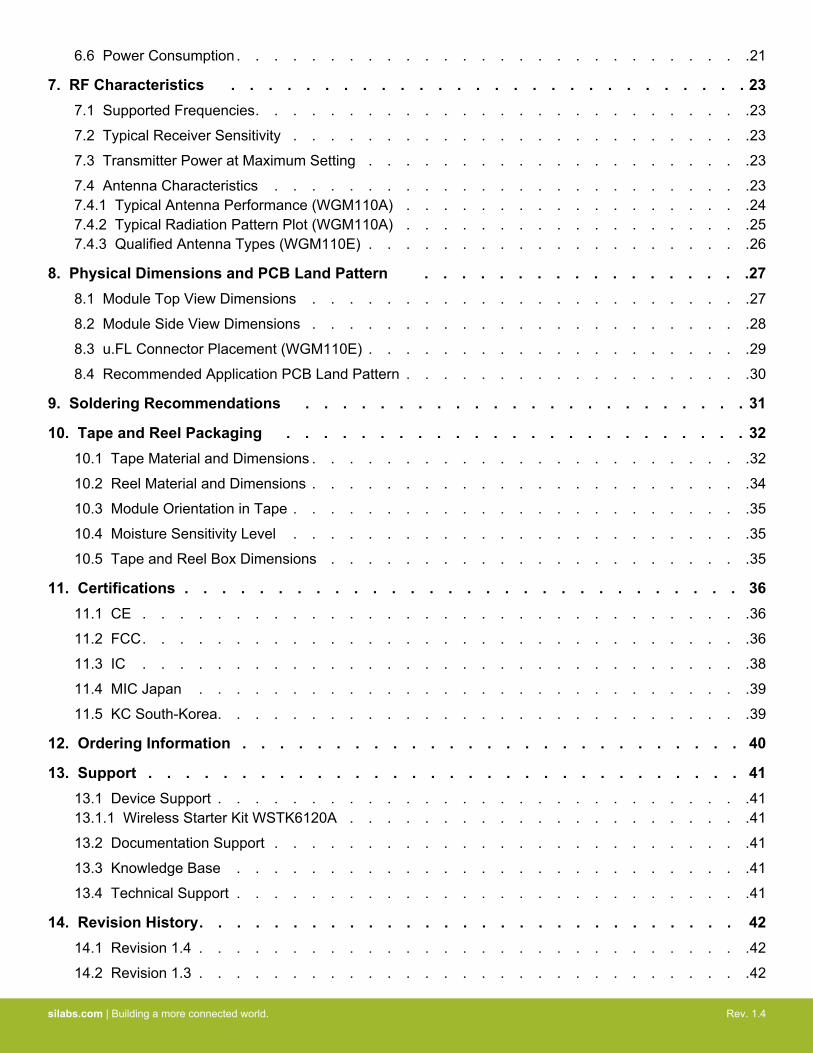
6.6 Power Consumption . . . . . . . . . . . . . . . . . . . . . . . . . . . .21
7. RF Characteristics . . . . . . . . . . . . . . . . . . . . . . . . . . . . 237.1 Supported Frequencies. . . . . . . . . . . . . . . . . . . . . . . . . . .23
7.2 Typical Receiver Sensitivity . . . . . . . . . . . . . . . . . . . . . . . . .23
7.3 Transmitter Power at Maximum Setting . . . . . . . . . . . . . . . . . . . . .23
7.4 Antenna Characteristics . . . . . . . . . . . . . . . . . . . . . . . . . .237.4.1 Typical Antenna Performance (WGM110A) . . . . . . . . . . . . . . . . . . .247.4.2 Typical Radiation Pattern Plot (WGM110A) . . . . . . . . . . . . . . . . . . .257.4.3 Qualified Antenna Types (WGM110E) . . . . . . . . . . . . . . . . . . . . .26
8. Physical Dimensions and PCB Land Pattern . . . . . . . . . . . . . . . . . .278.1 Module Top View Dimensions . . . . . . . . . . . . . . . . . . . . . . . .27
8.2 Module Side View Dimensions . . . . . . . . . . . . . . . . . . . . . . . .28
8.3 u.FL Connector Placement (WGM110E) . . . . . . . . . . . . . . . . . . . . .29
8.4 Recommended Application PCB Land Pattern . . . . . . . . . . . . . . . . . . .30
9. Soldering Recommendations . . . . . . . . . . . . . . . . . . . . . . . . 31
10. Tape and Reel Packaging . . . . . . . . . . . . . . . . . . . . . . . . . 3210.1 Tape Material and Dimensions . . . . . . . . . . . . . . . . . . . . . . . .32
10.2 Reel Material and Dimensions . . . . . . . . . . . . . . . . . . . . . . . .34
10.3 Module Orientation in Tape . . . . . . . . . . . . . . . . . . . . . . . . .35
10.4 Moisture Sensitivity Level . . . . . . . . . . . . . . . . . . . . . . . . .35
10.5 Tape and Reel Box Dimensions . . . . . . . . . . . . . . . . . . . . . . .35
11. Certifications . . . . . . . . . . . . . . . . . . . . . . . . . . . . . . 3611.1 CE . . . . . . . . . . . . . . . . . . . . . . . . . . . . . . . . .36
11.2 FCC. . . . . . . . . . . . . . . . . . . . . . . . . . . . . . . . .36
11.3 IC . . . . . . . . . . . . . . . . . . . . . . . . . . . . . . . . .38
11.4 MIC Japan . . . . . . . . . . . . . . . . . . . . . . . . . . . . . .39
11.5 KC South-Korea. . . . . . . . . . . . . . . . . . . . . . . . . . . . .39
12. Ordering Information . . . . . . . . . . . . . . . . . . . . . . . . . . . 40
13. Support . . . . . . . . . . . . . . . . . . . . . . . . . . . . . . . . 4113.1 Device Support . . . . . . . . . . . . . . . . . . . . . . . . . . . . .4113.1.1 Wireless Starter Kit WSTK6120A . . . . . . . . . . . . . . . . . . . . . .41
13.2 Documentation Support . . . . . . . . . . . . . . . . . . . . . . . . . .41
13.3 Knowledge Base . . . . . . . . . . . . . . . . . . . . . . . . . . . .41
13.4 Technical Support . . . . . . . . . . . . . . . . . . . . . . . . . . . .41
14. Revision History. . . . . . . . . . . . . . . . . . . . . . . . . . . . . 4214.1 Revision 1.4 . . . . . . . . . . . . . . . . . . . . . . . . . . . . . .42
14.2 Revision 1.3 . . . . . . . . . . . . . . . . . . . . . . . . . . . . . .42
silabs.com | Building a more connected world. Rev. 1.4
14.3 Revision 1.2 . . . . . . . . . . . . . . . . . . . . . . . . . . . . . .42
14.4 Revision 1.1 . . . . . . . . . . . . . . . . . . . . . . . . . . . . . .42
14.5 Revision 1.0 . . . . . . . . . . . . . . . . . . . . . . . . . . . . . .42
silabs.com | Building a more connected world. Rev. 1.4
第 1章 主な機能
WGM110 モジュールの主な特徴は以下のとおりです。
ラジオの特徴
• アンテナ
• チップ・アンテナ: WGM110A
• 外部アンテナ: WGM110E(U.FL コネクタ)
• TX 電力: +16 dBm
• RX 感度: -98 dBm
• 範囲: 最大 450 メートル
Wi-Fi 機能
• 802.11: b/g/n
• ビット・レート: 最大 72.2 Mbps
• 802.11 セキュリティ: WPA2/WPA Personal、WPA2/WPA Enter‐prise および WEP
• STA(ステーション・モード)
• SoftAP(ソフト・アクセス・ポイント・モード): 最大 5 つのクライアント
• Wi-Fi Direct
• WPS: 1.0(プッシュ・ボタン)
IP スタック
• IP バージョン: IPv4
• IP マルチキャスト
• TCP: クライアント/サーバ
• UDP: クライアント/サーバ
• TCP ソケット: 20+
• DHCP: クライアント/サーバ
• ARP
• DNS: クライアント/サーバ
• mDNS
• DNS-SD
• HTTP: サーバ
• TLS/SSL: クライアント
ソフトウェア API
• モデム使用向けの UART/SPI/USB を介した BGAPI™ シリアル・プロトコル API
• BGAPI シリアル・プロトコルを実装する BGLIB™ ホスト API
• スタンドアロン使用のための BGScript™ スクリプト言語
ソフトウェア開発ツール
• 無料の SDK
MCU スタック
• ARM® Cortex-M3
• 48 MHz
• 128 kB RAM
• 1 MB フラッシュ
ハードウェア・インターフェイス
• ホスト・インターフェイス: UART/SPI/USB
• ペリフェラル・インターフェイス
• 2 x USART (UART/SPI)
• 1 x USB(2.0 フルスピード)
• 2 x I2C ペリフェラル・インターフェイス
• 最大 32 x GPIO(割り込みあり)
• 8 チャンネル 12 ビット ADC
• 2 x タイマ(3 PWM の各タイマ)
• リアルタイム・カウンタ
電気的特性
• 供給電圧: 2.7 V ~ 4.8 V(無線ブロック)
• 供給電圧: 1.98 V ~ 3.8 V(プロセッサ・ブロック)
消費電力
• 261 mA の TX 電流(+16 dBm)
• 81 mA の RX 電流
• 2.4 mA の関連アイドル消費
• 18.8 μA のディープ・スリープ電流
環境仕様
• 温度範囲:-40°C ~ +85°C
モジュラー認証
• FCC
• IC
• 日本
• 韓国
CE 準拠
寸法
• 幅 x 長さ x 高さ:21.0 mm x 14.4 mm x 2.0 mm
WGM110 Wizard Gecko Wi-Fi® Module データシート
主な機能
silabs.com | Building a more connected world. Rev. 1.4 | 2
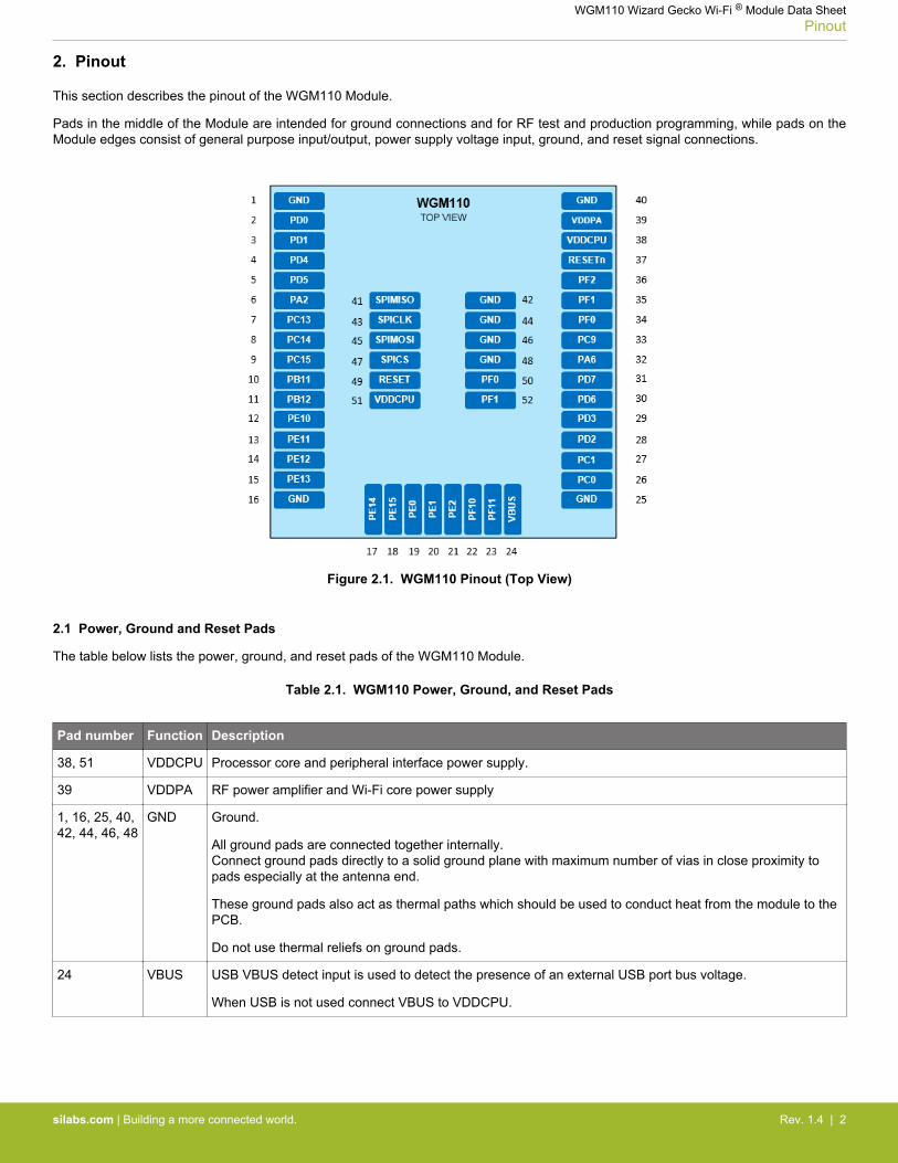
2. Pinout
This section describes the pinout of the WGM110 Module.
Pads in the middle of the Module are intended for ground connections and for RF test and production programming, while pads on theModule edges consist of general purpose input/output, power supply voltage input, ground, and reset signal connections.
Figure 2.1. WGM110 Pinout (Top View)
2.1 Power, Ground and Reset Pads
The table below lists the power, ground, and reset pads of the WGM110 Module.
Table 2.1. WGM110 Power, Ground, and Reset Pads
Pad number Function Description
38, 51 VDDCPU Processor core and peripheral interface power supply.
39 VDDPA RF power amplifier and Wi-Fi core power supply
1, 16, 25, 40,42, 44, 46, 48
GND Ground.
All ground pads are connected together internally.Connect ground pads directly to a solid ground plane with maximum number of vias in close proximity topads especially at the antenna end.
These ground pads also act as thermal paths which should be used to conduct heat from the module to thePCB.
Do not use thermal reliefs on ground pads.
24 VBUS USB VBUS detect input is used to detect the presence of an external USB port bus voltage.
When USB is not used connect VBUS to VDDCPU.
WGM110 Wizard Gecko Wi-Fi ® Module Data SheetPinout
silabs.com | Building a more connected world. Rev. 1.4 | 2
Pad number Function Description
37, 49 RESETn Reset signal input. To reset the Module pull this line low.
The reset signals resets both the MCU and the Wi-Fi radio.
Connected to an internal pull-up, can be left floating if not needed.
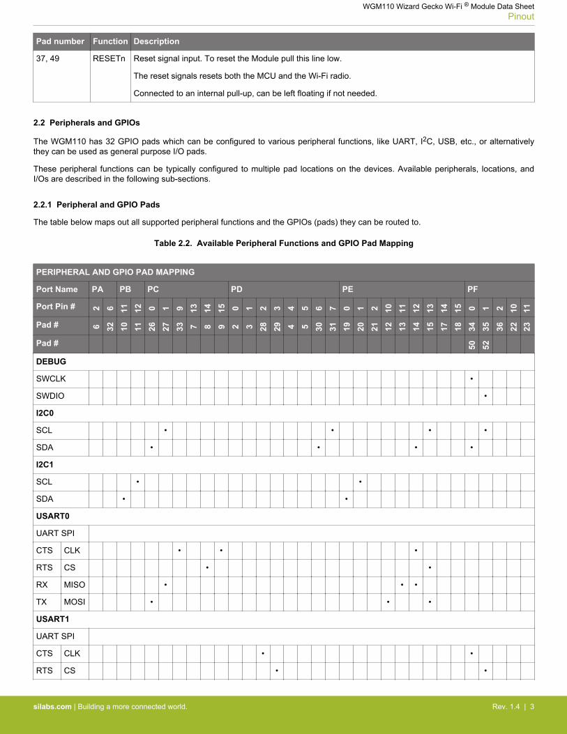
2.2 Peripherals and GPIOs
The WGM110 has 32 GPIO pads which can be configured to various peripheral functions, like UART, I2C, USB, etc., or alternativelythey can be used as general purpose I/O pads.
These peripheral functions can be typically configured to multiple pad locations on the devices. Available peripherals, locations, andI/Os are described in the following sub-sections.
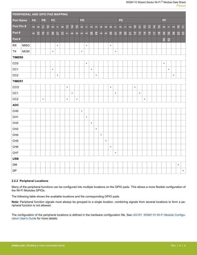
2.2.1 Peripheral and GPIO Pads
The table below maps out all supported peripheral functions and the GPIOs (pads) they can be routed to.
Table 2.2. Available Peripheral Functions and GPIO Pad Mapping
PERIPHERAL AND GPIO PAD MAPPING
Port Name PA PB PC PD PE PF
Port Pin # 2 6 11 12 0 1 9 13 14 15 0 1 2 3 4 5 6 7 0 1 2 10 11 12 13 14 15 0 1 2 10 11
Pad # 6 32 10 11 26 27 33 7 8 9 2 3 28 29 4 5 30 31 19 20 21 12 13 14 15 17 18 34 35 36 22 23
Pad # 50 52
DEBUG
SWCLK •
SWDIO •
I2C0
SCL • • • •
SDA • • • •
I2C1
SCL • •
SDA • •
USART0
UART SPI
CTS CLK • • •
RTS CS • •
RX MISO • • •
TX MOSI • • •
USART1
UART SPI
CTS CLK • •
RTS CS • •
WGM110 Wizard Gecko Wi-Fi ® Module Data SheetPinout
silabs.com | Building a more connected world. Rev. 1.4 | 3
PERIPHERAL AND GPIO PAD MAPPING
Port Name PA PB PC PD PE PF
Port Pin # 2 6 11 12 0 1 9 13 14 15 0 1 2 3 4 5 6 7 0 1 2 10 11 12 13 14 15 0 1 2 10 11
Pad # 6 32 10 11 26 27 33 7 8 9 2 3 28 29 4 5 30 31 19 20 21 12 13 14 15 17 18 34 35 36 22 23
Pad # 50 52
RX MISO • • •
TX MOSI • • •
TIMER0
CC0 • •
CC1 • • •
CC2 • • •
TIMER1
CCO • • •
CC1 • • •
CC2 • • • •
ADC
CH0 •
CH1 •
CH2 •
CH3 •
CH4 •
CH5 •
CH6 •
CH7 •
USB
DM •
DP •
2.2.2 Peripheral Locations
Many of the peripheral functions can be configured into multiple locations on the GPIO pads. This allows a more flexible configuration ofthe Wi-Fi Modules GPIOs.
The following table shows the available locations and the corresponding GPIO pads.
Note: Peripheral function signals must always be grouped to a single location, combining signals from several locations to form a pe-ripheral function is not allowed.
The configuration of the peripheral locations is defined in the hardware configuration file. See UG161: WGM110 Wi-Fi Module Configu-ration User's Guide for more details.
WGM110 Wizard Gecko Wi-Fi ® Module Data SheetPinout
silabs.com | Building a more connected world. Rev. 1.4 | 4
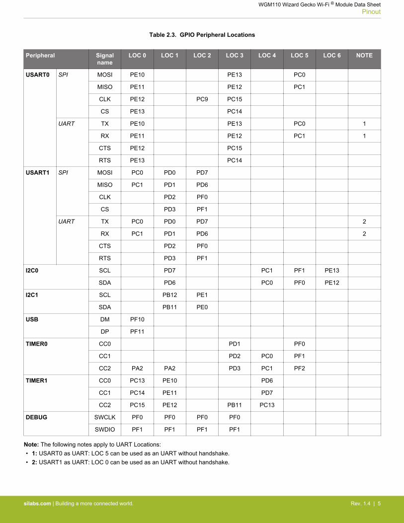
Table 2.3. GPIO Peripheral Locations
Peripheral Signalname
LOC 0 LOC 1 LOC 2 LOC 3 LOC 4 LOC 5 LOC 6 NOTE
USART0 SPI MOSI PE10 PE13 PC0
MISO PE11 PE12 PC1
CLK PE12 PC9 PC15
CS PE13 PC14
UART TX PE10 PE13 PC0 1
RX PE11 PE12 PC1 1
CTS PE12 PC15
RTS PE13 PC14
USART1 SPI MOSI PC0 PD0 PD7
MISO PC1 PD1 PD6
CLK PD2 PF0
CS PD3 PF1
UART TX PC0 PD0 PD7 2
RX PC1 PD1 PD6 2
CTS PD2 PF0
RTS PD3 PF1
I2C0 SCL PD7 PC1 PF1 PE13
SDA PD6 PC0 PF0 PE12
I2C1 SCL PB12 PE1
SDA PB11 PE0
USB DM PF10
DP PF11
TIMER0 CC0 PD1 PF0
CC1 PD2 PC0 PF1
CC2 PA2 PA2 PD3 PC1 PF2
TIMER1 CC0 PC13 PE10 PD6
CC1 PC14 PE11 PD7
CC2 PC15 PE12 PB11 PC13
DEBUG SWCLK PF0 PF0 PF0 PF0
SWDIO PF1 PF1 PF1 PF1
Note: The following notes apply to UART Locations:• 1: USART0 as UART: LOC 5 can be used as an UART without handshake.• 2: USART1 as UART: LOC 0 can be used as an UART without handshake.
WGM110 Wizard Gecko Wi-Fi ® Module Data SheetPinout
silabs.com | Building a more connected world. Rev. 1.4 | 5
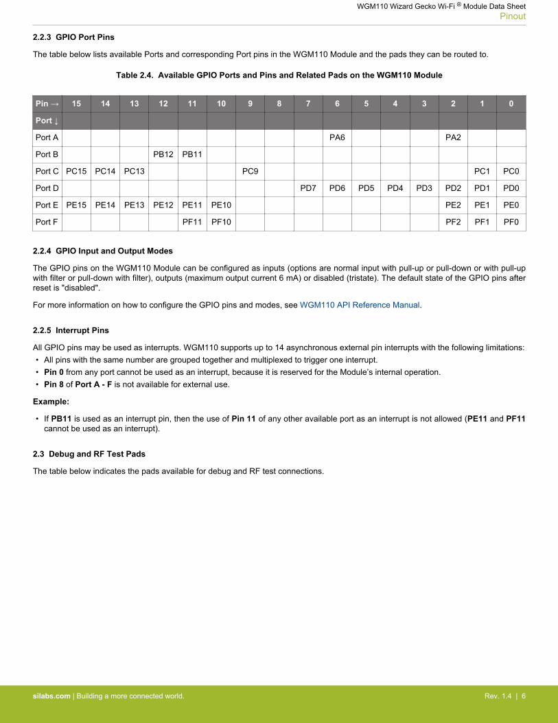
2.2.3 GPIO Port Pins
The table below lists available Ports and corresponding Port pins in the WGM110 Module and the pads they can be routed to.
Table 2.4. Available GPIO Ports and Pins and Related Pads on the WGM110 Module
Pin → 15 14 13 12 11 10 9 8 7 6 5 4 3 2 1 0
Port ↓
Port A PA6 PA2
Port B PB12 PB11
Port C PC15 PC14 PC13 PC9 PC1 PC0
Port D PD7 PD6 PD5 PD4 PD3 PD2 PD1 PD0
Port E PE15 PE14 PE13 PE12 PE11 PE10 PE2 PE1 PE0
Port F PF11 PF10 PF2 PF1 PF0
2.2.4 GPIO Input and Output Modes
The GPIO pins on the WGM110 Module can be configured as inputs (options are normal input with pull-up or pull-down or with pull-upwith filter or pull-down with filter), outputs (maximum output current 6 mA) or disabled (tristate). The default state of the GPIO pins afterreset is "disabled".
For more information on how to configure the GPIO pins and modes, see WGM110 API Reference Manual.
2.2.5 Interrupt Pins
All GPIO pins may be used as interrupts. WGM110 supports up to 14 asynchronous external pin interrupts with the following limitations:• All pins with the same number are grouped together and multiplexed to trigger one interrupt.• Pin 0 from any port cannot be used as an interrupt, because it is reserved for the Module’s internal operation.• Pin 8 of Port A - F is not available for external use.
Example:
• If PB11 is used as an interrupt pin, then the use of Pin 11 of any other available port as an interrupt is not allowed (PE11 and PF11cannot be used as an interrupt).
2.3 Debug and RF Test Pads
The table below indicates the pads available for debug and RF test connections.
WGM110 Wizard Gecko Wi-Fi ® Module Data SheetPinout
silabs.com | Building a more connected world. Rev. 1.4 | 6
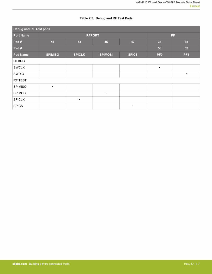
Table 2.5. Debug and RF Test Pads
Debug and RF Test pads
Port Name RFPORT PF
Pad # 41 43 45 47 34 35
Pad # 50 52
Pad Name SPIMISO SPICLK SPIMOSI SPICS PF0 PF1
DEBUG
SWCLK •
SWDIO •
RF TEST
SPIMISO •
SPIMOSI •
SPICLK •
SPICS •
WGM110 Wizard Gecko Wi-Fi ® Module Data SheetPinout
silabs.com | Building a more connected world. Rev. 1.4 | 7
3. Interfaces
This section describes the features and functionalities of the available host, peripheral, debug, and RF test interfaces.
3.1 Host Interfaces
There are three available host interfaces one of which can be used to connect an external host, typically an MCU, to the WGM110 Wi-Fi Module and use it as a Wi-Fi modem.
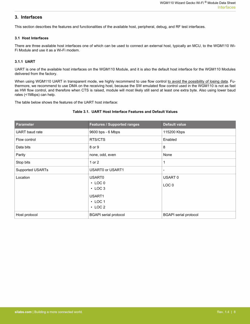
3.1.1 UART
UART is one of the available host interfaces on the WGM110 Module, and it is also the default host interface for the WGM110 Modulesdelivered from the factory.
When using WGM110 UART in transparent mode, we highly recommend to use flow control to avoid the possibility of losing data. Fu-thermore, we recommend to use DMA on the receiving host, because the SW emulated flow control used in the WGM110 is not as fastas HW flow control, and therefore when CTS is raised, module will most likely still send at least one extra byte. Also using lower baudrates (<1Mbps) can help.
The table below shows the features of the UART host interface:
Table 3.1. UART Host Interface Features and Default Values
Parameter Features / Supported ranges Default value
UART baud rate 9600 bps - 6 Mbps 115200 Kbps
Flow control RTS/CTS Enabled
Data bits 8 or 9 8
Parity none, odd, even None
Stop bits 1 or 2 1
Supported USARTs USART0 or USART1 -
Location USART0• LOC 0• LOC 3
USART1• LOC 1• LOC 2
USART 0
LOC 0
Host protocol BGAPI serial protocol BGAPI serial protocol
WGM110 Wizard Gecko Wi-Fi ® Module Data SheetInterfaces
silabs.com | Building a more connected world. Rev. 1.4 | 8
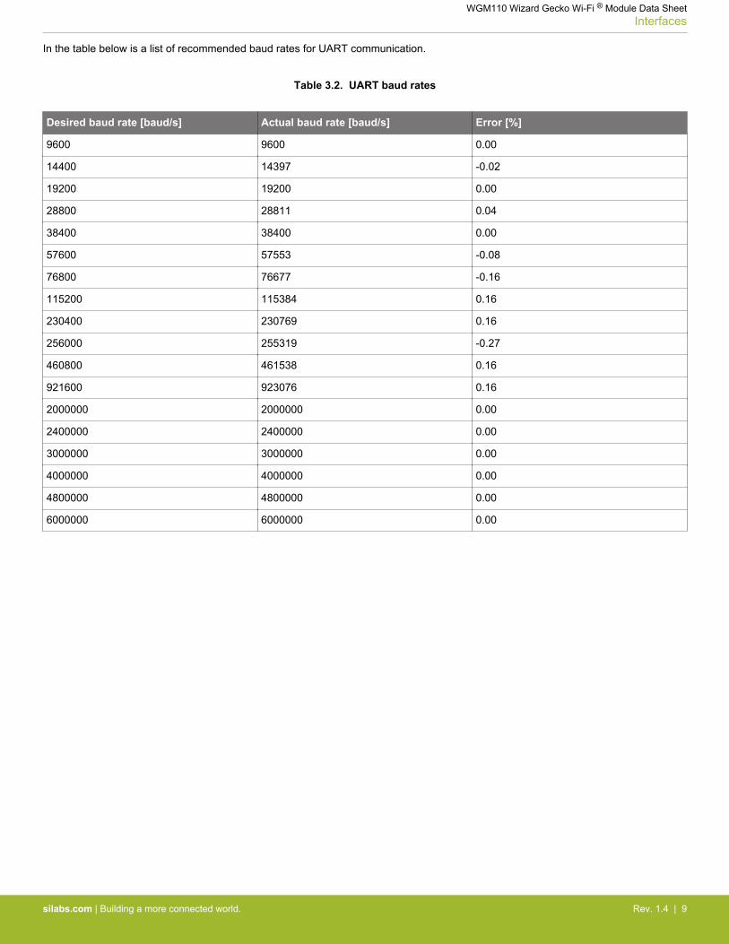
In the table below is a list of recommended baud rates for UART communication.
Table 3.2. UART baud rates
Desired baud rate [baud/s] Actual baud rate [baud/s] Error [%]
9600 9600 0.00
14400 14397 -0.02
19200 19200 0.00
28800 28811 0.04
38400 38400 0.00
57600 57553 -0.08
76800 76677 -0.16
115200 115384 0.16
230400 230769 0.16
256000 255319 -0.27
460800 461538 0.16
921600 923076 0.16
2000000 2000000 0.00
2400000 2400000 0.00
3000000 3000000 0.00
4000000 4000000 0.00
4800000 4800000 0.00
6000000 6000000 0.00
WGM110 Wizard Gecko Wi-Fi ® Module Data SheetInterfaces
silabs.com | Building a more connected world. Rev. 1.4 | 9
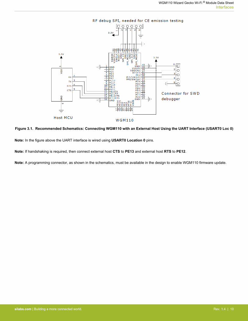
Figure 3.1. Recommended Schematics: Connecting WGM110 with an External Host Using the UART Interface (USART0 Loc 0)
Note: In the figure above the UART interface is wired using USART0 Location 0 pins.
Note: If handshaking is required, then connect external host CTS to PE13 and external host RTS to PE12.
Note: A programming connector, as shown in the schematics, must be available in the design to enable WGM110 firmware update.
WGM110 Wizard Gecko Wi-Fi ® Module Data SheetInterfaces
silabs.com | Building a more connected world. Rev. 1.4 | 10
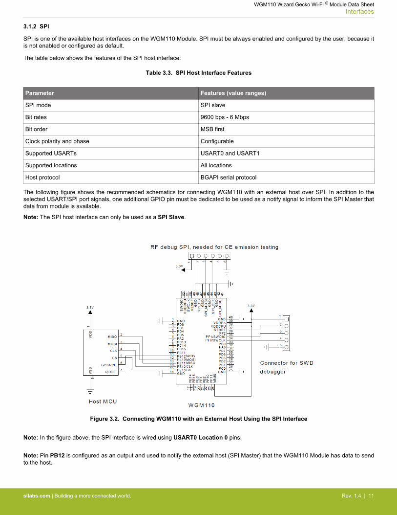
3.1.2 SPI
SPI is one of the available host interfaces on the WGM110 Module. SPI must be always enabled and configured by the user, because itis not enabled or configured as default.
The table below shows the features of the SPI host interface:
Table 3.3. SPI Host Interface Features
Parameter Features (value ranges)
SPI mode SPI slave
Bit rates 9600 bps - 6 Mbps
Bit order MSB first
Clock polarity and phase Configurable
Supported USARTs USART0 and USART1
Supported locations All locations
Host protocol BGAPI serial protocol
The following figure shows the recommended schematics for connecting WGM110 with an external host over SPI. In addition to theselected USART/SPI port signals, one additional GPIO pin must be dedicated to be used as a notify signal to inform the SPI Master thatdata from module is available.
Note: The SPI host interface can only be used as a SPI Slave.
Figure 3.2. Connecting WGM110 with an External Host Using the SPI Interface
Note: In the figure above, the SPI interface is wired using USART0 Location 0 pins.
Note: Pin PB12 is configured as an output and used to notify the external host (SPI Master) that the WGM110 Module has data to sendto the host.
WGM110 Wizard Gecko Wi-Fi ® Module Data SheetInterfaces
silabs.com | Building a more connected world. Rev. 1.4 | 11
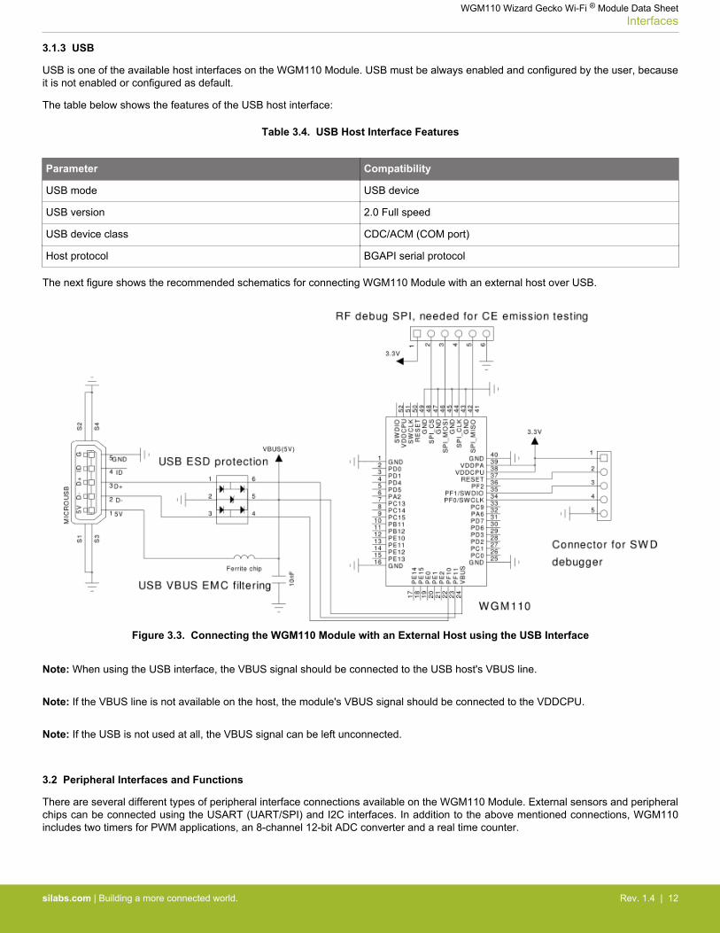
3.1.3 USB
USB is one of the available host interfaces on the WGM110 Module. USB must be always enabled and configured by the user, becauseit is not enabled or configured as default.
The table below shows the features of the USB host interface:
Table 3.4. USB Host Interface Features
Parameter Compatibility
USB mode USB device
USB version 2.0 Full speed
USB device class CDC/ACM (COM port)
Host protocol BGAPI serial protocol
The next figure shows the recommended schematics for connecting WGM110 Module with an external host over USB.
Figure 3.3. Connecting the WGM110 Module with an External Host using the USB Interface
Note: When using the USB interface, the VBUS signal should be connected to the USB host's VBUS line.
Note: If the VBUS line is not available on the host, the module's VBUS signal should be connected to the VDDCPU.
Note: If the USB is not used at all, the VBUS signal can be left unconnected.
3.2 Peripheral Interfaces and Functions
There are several different types of peripheral interface connections available on the WGM110 Module. External sensors and peripheralchips can be connected using the USART (UART/SPI) and I2C interfaces. In addition to the above mentioned connections, WGM110includes two timers for PWM applications, an 8-channel 12-bit ADC converter and a real time counter.
WGM110 Wizard Gecko Wi-Fi ® Module Data SheetInterfaces
silabs.com | Building a more connected world. Rev. 1.4 | 12
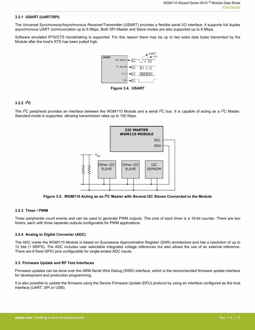
3.2.1 USART (UART/SPI)
The Universal Synchronous/Asynchronous Receiver/Transmitter (USART) provides a flexible serial I/O interface. It supports full duplexasynchronous UART communication up to 6 Mbps. Both SPI Master and Slave modes are also supported up to 6 Mbps.
Software emulated RTS/CTS handshaking is supported. For this reason there may be up to two extra data bytes transmited by theModule after the host's RTS has been pulled high.
Figure 3.4. USART
3.2.2 I2C
The I2C peripheral provides an interface between the WGM110 Module and a serial I2C bus. It is capable of acting as a I2C Master.Standard-mode is supported, allowing transmission rates up to 100 Kbps.
Figure 3.5. WGM110 Acting as an I2C Master with Several I2C Slaves Connected to the Module
3.2.3 Timer / PWM
Timer peripherals count events and can be used to generate PWM outputs. The core of each timer is a 16-bit counter. There are twotimers, each with three separate outputs configurable for PWM applications.
3.2.4 Analog to Digital Converter (ADC)
The ADC inside the WGM110 Module is based on Successive Approximation Register (SAR) architecture and has a resolution of up to12 bits (1 MSPS). The ADC includes user selectable integrated voltage references but also allows the use of an external reference.There are 8 fixed GPIO pins configurable for single-ended ADC inputs.
3.3 Firmware Update and RF Test Interfaces
Firmware updates can be done over the ARM Serial Wire Debug (SWD) interface, which is the recommended firmware update interfacefor development and production programming.
It is also possible to update the firmware using the Device Firmware Update (DFU) protocol by using an interface configured as the hostinterface (UART, SPI or USB).
WGM110 Wizard Gecko Wi-Fi ® Module Data SheetInterfaces
silabs.com | Building a more connected world. Rev. 1.4 | 13
3.3.1 ARM Serial Wire Debug (SWD)
The WGM110 Module contains a 2-wire ARM SWD interface for programming and debugging. It is recommended that the pads of thisinterface are exposed in the application design to allow firmware updates and debugging.
3.3.2 Device Firmware Upgrade (DFU)
The firmware can be updated over the configured host interface (UART, SPI, or USB) using the Device Firmware Upgrade (DFU) proto-col. This method is intended to be used for field updates of the firmware, for example, when updating the WGM110 Module firmwarefrom a connected host using the BGAPI serial protocol.
Note: You cannot update the bootloader using the DFU protocol. Bootloader update must be done using the SWD Debug interface.
Note: In case the DFU recovery mode is not useable for any reason, the SWD bus is always available at boot when the RESET pin ofthe WGM110 Module is being pulled down.
3.3.3 RF Test Interface
There are dedicated pads on the WGM110 Module that are used to enable the Wi-Fi radio test modes. These test modes would typical-ly be used if RF measurements relating to CE or any other certification requirements are needed. More specifically, RF Test pads areused to enable the TX and RX test modes of the WGM110 Module.
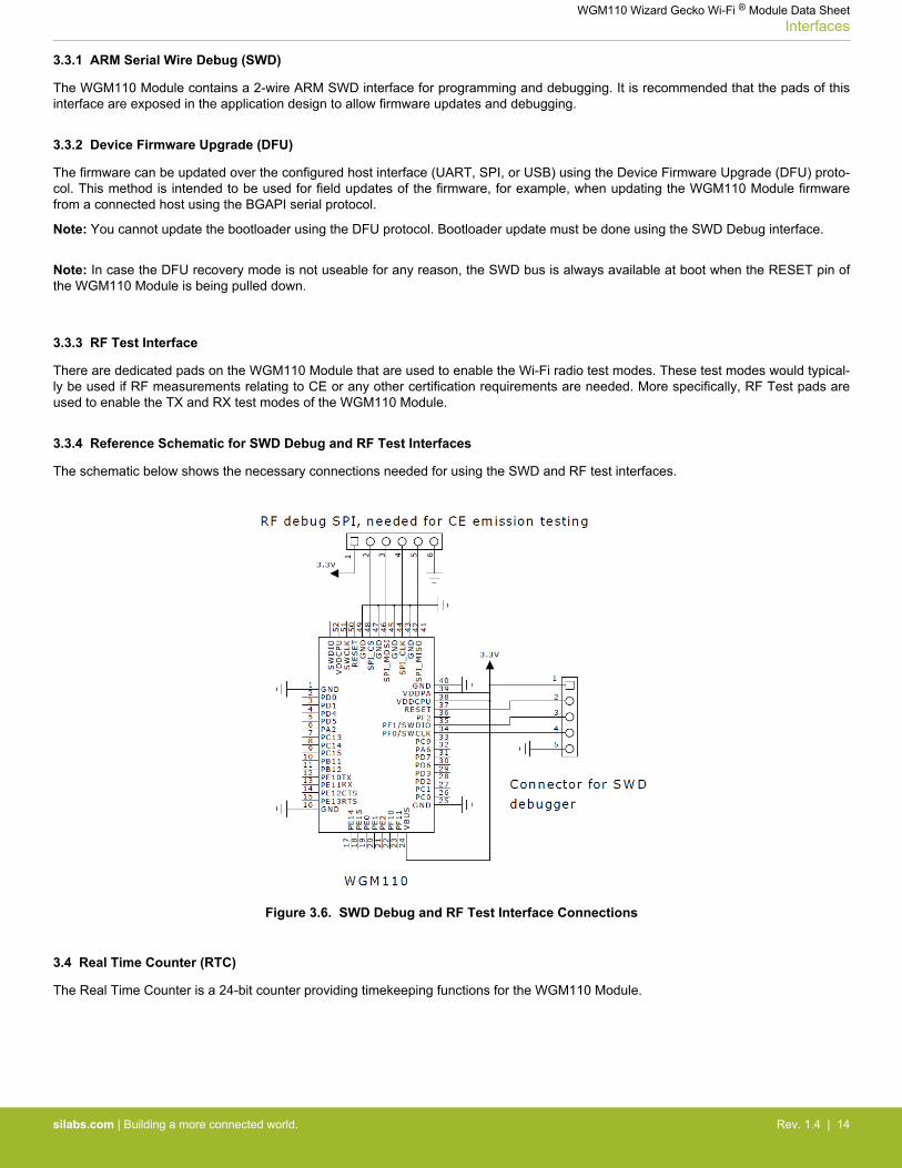
3.3.4 Reference Schematic for SWD Debug and RF Test Interfaces
The schematic below shows the necessary connections needed for using the SWD and RF test interfaces.
Figure 3.6. SWD Debug and RF Test Interface Connections
3.4 Real Time Counter (RTC)
The Real Time Counter is a 24-bit counter providing timekeeping functions for the WGM110 Module.
WGM110 Wizard Gecko Wi-Fi ® Module Data SheetInterfaces
silabs.com | Building a more connected world. Rev. 1.4 | 14
4. Module Software
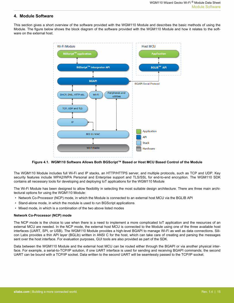
This section gives a short overview of the software provided with the WGM110 Module and describes the basic methods of using theModule. The figure below shows the block diagram of the software provided with the WGM110 Module and how it relates to the soft-ware on the external host.
Figure 4.1. WGM110 Software Allows Both BGScript™ Based or Host MCU Based Control of the Module
The WGM110 Module includes full Wi-Fi and IP stacks, an HTTP/HTTPS server, and multiple protocols, such as TCP and UDP. Keysecurity features include WPA2/WPA Personal and Enterprise support and TLS/SSL for end-to-end encryption. The WGM110 SDKcontains all necessary tools for developing and deploying IoT applications for the WGM110 Module
The Wi-Fi Module has been designed to allow flexibility in selecting the most suitable design architecture. There are three main archi-tectural options for using the WGM110 Module:• Network Co-Processor (NCP) mode, in which the Module is connected to an external host MCU via the BGLIB API• Stand-alone mode, in which the module is used to run BGScript applications• Mixed mode, in which is a combination of the two above listed modes
Network Co-Processor (NCP) mode
The NCP mode is the choice to use when there is a need to implement a more complicated IoT application and the resources of anexternal MCU are needed. In the NCP mode, the external host MCU is connected to the Module using one of the three available hostinterfaces (UART, SPI, or USB). The WGM110 Module provides a high-level BGAPI to manage Wi-Fi as well as data connections. Sili-con Labs provides a thin API layer (BGLib) written in ANSI C for the host, which can take care of creating and parsing the messagessent over the host interface. For evaluation purposes, GUI tools are also provided as part of the SDK.
Data between the WGM110 Module and the external host MCU can be routed either through the BGAPI or via another physical inter-face. For example, a serial-to-TCP/IP solution, if one UART interface is used for sending and receiving BGAPI commands; the secondUART can be bound with a TCP/IP socket. Data written to the second UART will be seamlessly passed to the TCP/IP socket.
WGM110 Wizard Gecko Wi-Fi ® Module Data SheetModule Software
silabs.com | Building a more connected world. Rev. 1.4 | 15

Stand-alone mode
The stand-alone mode is especially suitable for more lightweight IoT applications, and there is no need for hosting an external MCUcontroller. This will naturally result in HW BOM cost savings. The WGM110 Module is natively running and controlled by a BGScriptapplication.
Mixed mode
The WGM110 Module can also be used in a mixed mode, where both the NCP and Stand-alone approaches are used in parallel. In thiscase the BGScript application on the module can be run completely independent from any MCU action. Normally the approach is toautomate certain processes in BGScript (e.g. Wi-Fi network scanning and connection) to relieve the host from doing these.
Note: To learn more about the WGM110 Module software, the SDK and the APIs in general please read the QSG122: WGM110 Wi-FiModule Software Quick-Start Guide.
Note: For a complete reference of the API, please see the WGM110 API Reference Manual.
WGM110 Wizard Gecko Wi-Fi ® Module Data SheetModule Software
silabs.com | Building a more connected world. Rev. 1.4 | 16
5. Hardware Design Guidelines
WGM110 is an easy-to use Module with regard to hardware application design, but certain guidelines must be followed to guaranteeoptimal performance. These guidelines are listed in the next sub-sections.
5.1 Power Supply Requirements
WGM110 Module consists of two separate internal blocks, the microcontroller and the Wi-Fi radio block. Individual power supplies areneeded for both the MCU and the Wi-Fi radio blocks.
The WGM110 Module is designed to operate with a 3.3 V nominal input voltage supplied to the two supply inputs as follows:• The VDDCPU powers the MCU and can be fed with a voltage between 2.0 V and 3.8 V. The regulator supplying VDDCPU should be
able to supply at least 30 mA.• The VDDPA pad can be supplied with a voltage between 2.7 V and 4.8 V and supplies the RF power amplifier and the internal
switch-mode converter powering the Wi-Fi digital core. VDDPA may draw short peaks up to 350 mA.
In lithium battery powered applications, VDDPA can be connected directly to the battery, while a regulator is needed to supply theVDDCPU with a lower voltage, as needed by the design. Care should be taken that the supply source is capable of supplying enoughcurrent for the heavy load peaks of the power amplifier.
External high frequency bypass capacitors are not needed because the module contains the required supply filter capacitors. However,care should be taken to prevent strong switching noise from being superimposed on the supply lines. Such noise can be generated, forexample, by on-board charge pump converters used in RS232 level shifters. Note that there is a total of about 20 µF of low ESR ceram-ic capacitors on the VDDPA line and approximately 2 µF on the VDDCPU line inside the module. When using external regulators togenerate regulated supplies for the module, the stability of the regulator with the low ESR provided by these capacitors should bechecked. Many low-drop linear regulators and some switched mode regulators are not stable when using ceramic output capacitors.The datasheet of the regulator typically lists recommendations concerning suitable capacitors, including data on ESR range and/or sta-bility curves. A regulator with a statement “stable with ceramic capacitors” is recommended.
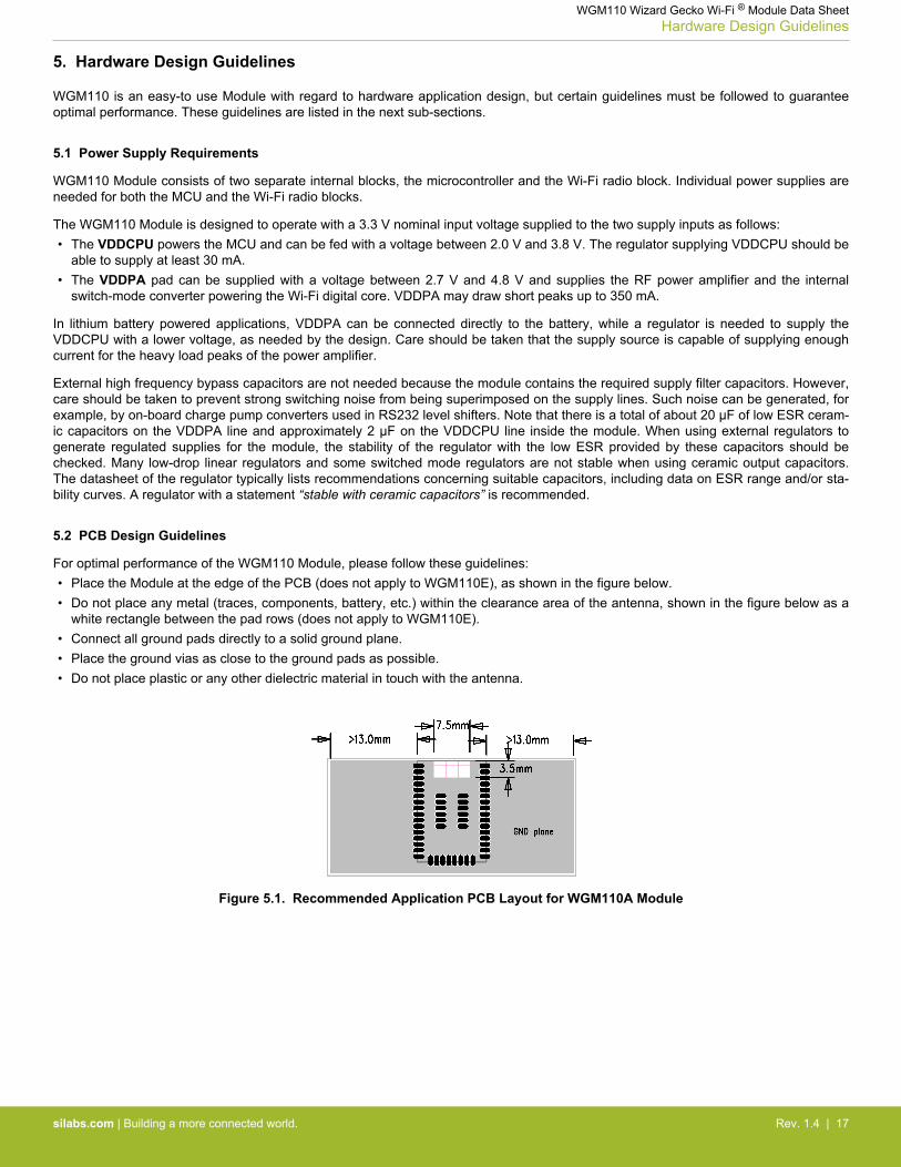
5.2 PCB Design Guidelines
For optimal performance of the WGM110 Module, please follow these guidelines:• Place the Module at the edge of the PCB (does not apply to WGM110E), as shown in the figure below.• Do not place any metal (traces, components, battery, etc.) within the clearance area of the antenna, shown in the figure below as a
white rectangle between the pad rows (does not apply to WGM110E).• Connect all ground pads directly to a solid ground plane.• Place the ground vias as close to the ground pads as possible.• Do not place plastic or any other dielectric material in touch with the antenna.
Figure 5.1. Recommended Application PCB Layout for WGM110A Module
WGM110 Wizard Gecko Wi-Fi ® Module Data SheetHardware Design Guidelines
silabs.com | Building a more connected world. Rev. 1.4 | 17
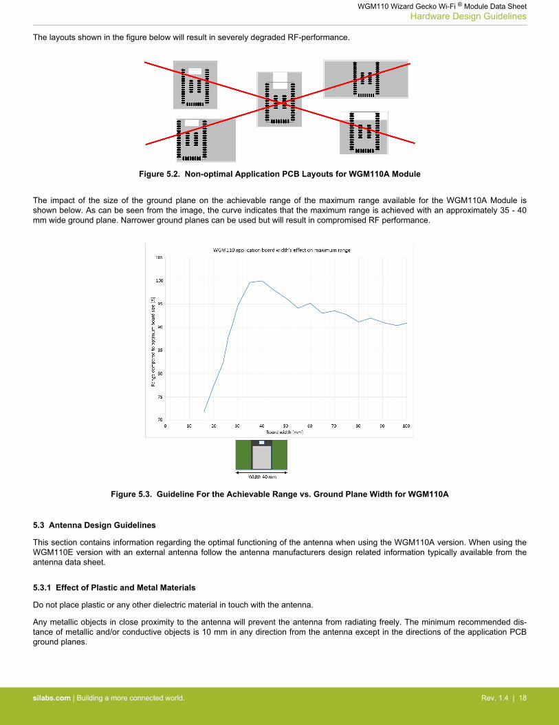
The layouts shown in the figure below will result in severely degraded RF-performance.
Figure 5.2. Non-optimal Application PCB Layouts for WGM110A Module
The impact of the size of the ground plane on the achievable range of the maximum range available for the WGM110A Module isshown below. As can be seen from the image, the curve indicates that the maximum range is achieved with an approximately 35 - 40mm wide ground plane. Narrower ground planes can be used but will result in compromised RF performance.
Figure 5.3. Guideline For the Achievable Range vs. Ground Plane Width for WGM110A
5.3 Antenna Design Guidelines
This section contains information regarding the optimal functioning of the antenna when using the WGM110A version. When using theWGM110E version with an external antenna follow the antenna manufacturers design related information typically available from theantenna data sheet.
5.3.1 Effect of Plastic and Metal Materials
Do not place plastic or any other dielectric material in touch with the antenna.
Any metallic objects in close proximity to the antenna will prevent the antenna from radiating freely. The minimum recommended dis-tance of metallic and/or conductive objects is 10 mm in any direction from the antenna except in the directions of the application PCBground planes.
WGM110 Wizard Gecko Wi-Fi ® Module Data SheetHardware Design Guidelines
silabs.com | Building a more connected world. Rev. 1.4 | 18
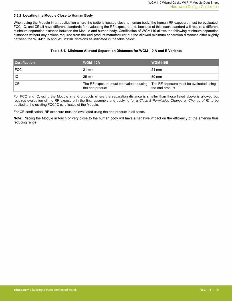
5.3.2 Locating the Module Close to Human Body
When using the Module in an application where the radio is located close to human body, the human RF exposure must be evaluated.FCC, IC, and CE all have different standards for evaluating the RF exposure and, because of this, each standard will require a differentminimum separation distance between the Module and human body. Certification of WGM110 allows the following minimum separationdistances without any actions required from the end product manufacturer but the allowed minimum separation distances differ slightlybetween the WGM110A and WGM110E versions as indicated in the table below.
Table 5.1. Minimum Allowed Separation Distances for WGM110 A and E Variants
Certification WGM110A WGM110E
FCC 21 mm 21 mm
IC 25 mm 30 mm
CE The RF exposure must be evaluated usingthe end product
The RF exposure must be evaluated usingthe end product
For FCC and IC, using the Module in end products where the separation distance is smaller than those listed above is allowed butrequires evaluation of the RF exposure in the final assembly and applying for a Class 2 Permissive Change or Change of ID to beapplied to the existing FCC/IC certificates of the Module.
For CE certification, RF exposure must be evaluated using the end product in all cases.
Note: Placing the Module in touch or very close to the human body will have a negative impact on the efficiency of the antenna thusreducing range.
WGM110 Wizard Gecko Wi-Fi ® Module Data SheetHardware Design Guidelines
silabs.com | Building a more connected world. Rev. 1.4 | 19
6. Electrical Characteristics
This section contains tables with electrical characteristics of WGM110 Module.
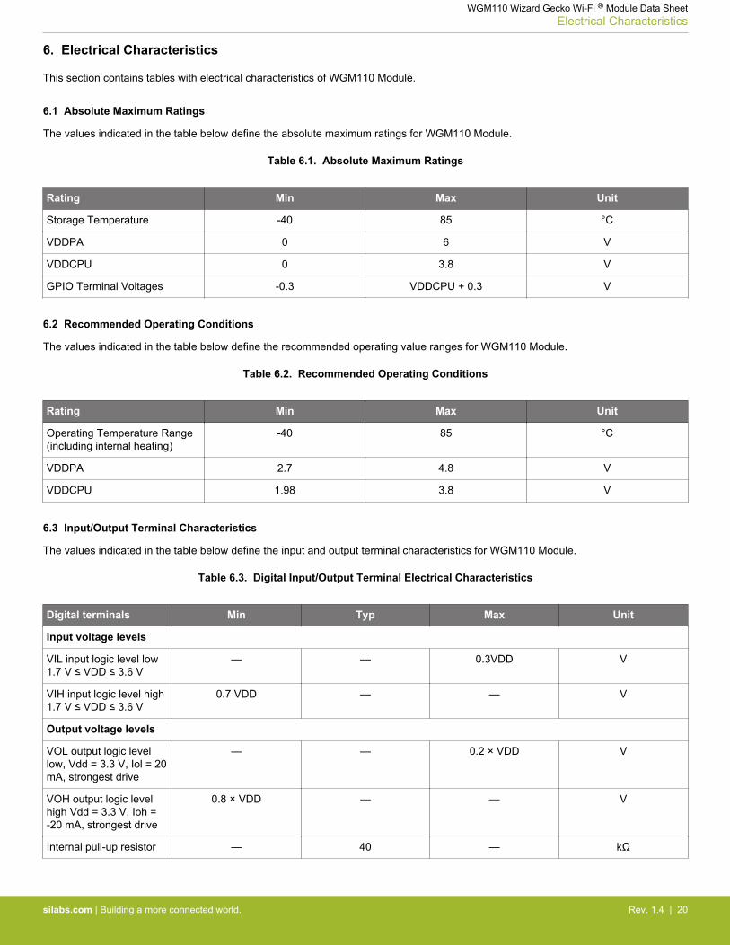
6.1 Absolute Maximum Ratings
The values indicated in the table below define the absolute maximum ratings for WGM110 Module.
Table 6.1. Absolute Maximum Ratings
Rating Min Max Unit
Storage Temperature -40 85 °C
VDDPA 0 6 V
VDDCPU 0 3.8 V
GPIO Terminal Voltages -0.3 VDDCPU + 0.3 V
6.2 Recommended Operating Conditions
The values indicated in the table below define the recommended operating value ranges for WGM110 Module.
Table 6.2. Recommended Operating Conditions
Rating Min Max Unit
Operating Temperature Range(including internal heating)
-40 85 °C
VDDPA 2.7 4.8 V
VDDCPU 1.98 3.8 V
6.3 Input/Output Terminal Characteristics
The values indicated in the table below define the input and output terminal characteristics for WGM110 Module.
Table 6.3. Digital Input/Output Terminal Electrical Characteristics
Digital terminals Min Typ Max Unit
Input voltage levels
VIL input logic level low1.7 V ≤ VDD ≤ 3.6 V
— — 0.3VDD V
VIH input logic level high1.7 V ≤ VDD ≤ 3.6 V
0.7 VDD — — V
Output voltage levels
VOL output logic levellow, Vdd = 3.3 V, Iol = 20mA, strongest drive
— — 0.2 × VDD V
VOH output logic levelhigh Vdd = 3.3 V, Ioh =-20 mA, strongest drive
0.8 × VDD — — V
Internal pull-up resistor — 40 — kΩ
WGM110 Wizard Gecko Wi-Fi ® Module Data SheetElectrical Characteristics
silabs.com | Building a more connected world. Rev. 1.4 | 20
Digital terminals Min Typ Max Unit
Internal pull-down resis-tor
— 40 — kΩ
Pulse width of pulses tobe removed by the glitchsuppression filter whenenabled
10 50 ns
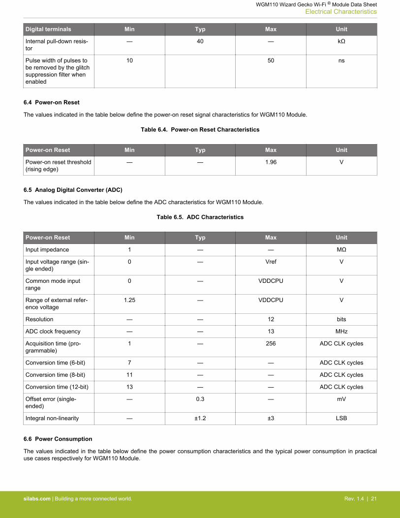
6.4 Power-on Reset
The values indicated in the table below define the power-on reset signal characteristics for WGM110 Module.
Table 6.4. Power-on Reset Characteristics
Power-on Reset Min Typ Max Unit
Power-on reset threshold(rising edge)
— — 1.96 V
6.5 Analog Digital Converter (ADC)
The values indicated in the table below define the ADC characteristics for WGM110 Module.
Table 6.5. ADC Characteristics
Power-on Reset Min Typ Max Unit
Input impedance 1 — — MΩ
Input voltage range (sin-gle ended)
0 — Vref V
Common mode inputrange
0 — VDDCPU V
Range of external refer-ence voltage
1.25 — VDDCPU V
Resolution — — 12 bits
ADC clock frequency — — 13 MHz
Acquisition time (pro-grammable)
1 — 256 ADC CLK cycles
Conversion time (6-bit) 7 — — ADC CLK cycles
Conversion time (8-bit) 11 — — ADC CLK cycles
Conversion time (12-bit) 13 — — ADC CLK cycles
Offset error (single-ended)
— 0.3 — mV
Integral non-linearity — ±1.2 ±3 LSB
6.6 Power Consumption
The values indicated in the table below define the power consumption characteristics and the typical power consumption in practicaluse cases respectively for WGM110 Module.
WGM110 Wizard Gecko Wi-Fi ® Module Data SheetElectrical Characteristics
silabs.com | Building a more connected world. Rev. 1.4 | 21
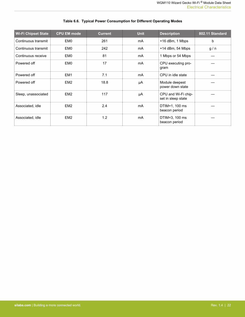
Table 6.6. Typical Power Consumption for Different Operating Modes
Wi-Fi Chipset State CPU EM mode Current Unit Description 802.11 Standard
Continuous transmit EM0 261 mA +16 dBm, 1 Mbps b
Continuous transmit EM0 242 mA +14 dBm, 54 Mbps g / n
Continuous receive EM0 81 mA 1 Mbps or 54 Mbps —
Powered off EM0 17 mA CPU executing pro-gram
—
Powered off EM1 7.1 mA CPU in idle state —
Powered off EM2 18.8 μA Module deepestpower down state
—
Sleep, unassociated EM2 117 μA CPU and Wi-Fi chip-set in sleep state
—
Associated, idle EM2 2.4 mA DTIM=1, 100 msbeacon period
—
Associated, idle EM2 1.2 mA DTIM=3, 100 msbeacon period
—
WGM110 Wizard Gecko Wi-Fi ® Module Data SheetElectrical Characteristics
silabs.com | Building a more connected world. Rev. 1.4 | 22
7. RF Characteristics
This section contains tables with RF characteristics of the WGM110 Module.
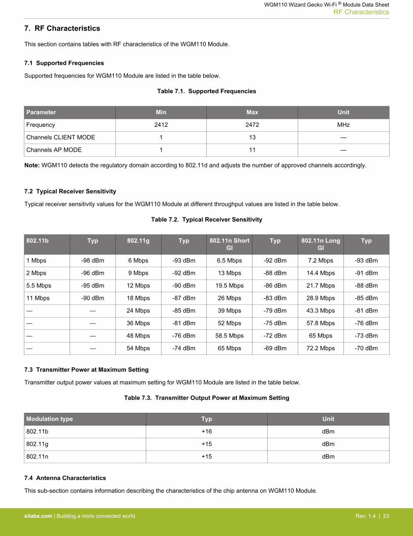
7.1 Supported Frequencies
Supported frequencies for WGM110 Module are listed in the table below.
Table 7.1. Supported Frequencies
Parameter Min Max Unit
Frequency 2412 2472 MHz
Channels CLIENT MODE 1 13 —
Channels AP MODE 1 11 —
Note: WGM110 detects the regulatory domain according to 802.11d and adjusts the number of approved channels accordingly.
7.2 Typical Receiver Sensitivity
Typical receiver sensitivity values for the WGM110 Module at different throughput values are listed in the table below.
Table 7.2. Typical Receiver Sensitivity
802.11b Typ 802.11g Typ 802.11n ShortGI
Typ 802.11n LongGI
Typ
1 Mbps -98 dBm 6 Mbps -93 dBm 6.5 Mbps -92 dBm 7.2 Mbps -93 dBm
2 Mbps -96 dBm 9 Mbps -92 dBm 13 Mbps -88 dBm 14.4 Mbps -91 dBm
5.5 Mbps -95 dBm 12 Mbps -90 dBm 19.5 Mbps -86 dBm 21.7 Mbps -88 dBm
11 Mbps -90 dBm 18 Mbps -87 dBm 26 Mbps -83 dBm 28.9 Mbps -85 dBm
— — 24 Mbps -85 dBm 39 Mbps -79 dBm 43.3 Mbps -81 dBm
— — 36 Mbps -81 dBm 52 Mbps -75 dBm 57.8 Mbps -76 dBm
— — 48 Mbps -76 dBm 58.5 Mbps -72 dBm 65 Mbps -73 dBm
— — 54 Mbps -74 dBm 65 Mbps -69 dBm 72.2 Mbps -70 dBm
7.3 Transmitter Power at Maximum Setting
Transmitter output power values at maximum setting for WGM110 Module are listed in the table below.
Table 7.3. Transmitter Output Power at Maximum Setting
Modulation type Typ Unit
802.11b +16 dBm
802.11g +15 dBm
802.11n +15 dBm
7.4 Antenna Characteristics
This sub-section contains information describing the characteristics of the chip antenna on WGM110 Module.
WGM110 Wizard Gecko Wi-Fi ® Module Data SheetRF Characteristics
silabs.com | Building a more connected world. Rev. 1.4 | 23

7.4.1 Typical Antenna Performance (WGM110A)
Typical antenna performance values for WGM110A Module are listed in the following table.
Table 7.4. Typical Antenna Performance for WGM110 Module
Parameter Typ Unit
Antenna efficiency - 2 ... -6 dB
Antenna peak gain +1 ... -2 dBi
WGM110 Wizard Gecko Wi-Fi ® Module Data SheetRF Characteristics
silabs.com | Building a more connected world. Rev. 1.4 | 24
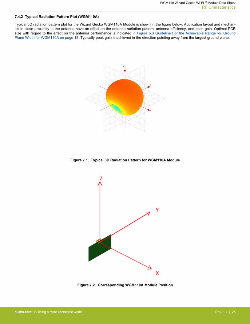
7.4.2 Typical Radiation Pattern Plot (WGM110A)
Typical 3D radiation pattern plot for the Wizard Gecko WGM110A Module is shown in the figure below. Application layout and mechan-ics in close proximity to the antenna have an effect on the antenna radiation pattern, antenna efficiency, and peak gain. Optimal PCBsize with regard to the effect on the antenna performance is indicated in Figure 5.3 Guideline For the Achievable Range vs. GroundPlane Width for WGM110A on page 18. Typically peak gain is achieved in the direction pointing away from the largest ground plane.
Figure 7.1. Typical 3D Radiation Pattern for WGM110A Module
Figure 7.2. Corresponding WGM110A Module Position
WGM110 Wizard Gecko Wi-Fi ® Module Data SheetRF Characteristics
silabs.com | Building a more connected world. Rev. 1.4 | 25

7.4.3 Qualified Antenna Types (WGM110E)
This device has been designed to operate with antennas having a maximum gain of 2.8 dB (see table below). Antenna types not listedin the table and/or antennas having a gain greater than 2.8 dB are strictly prohibited for use with this device. The required antennaimpedance is 50 Ω.
Table 7.5. Qualified Antenna Types for WGM110E
Qualified Antenna Types for WGM110E
Antenna type Maximum Gain
Dipole 2.8 dBi
Any antenna that is of the same type and of equal or less directional gain as listed in the above table can be used without a need forretesting. To reduce potential radio interference to other users, the antenna type and its gain should be selected so that the equivalentisotropically radiated power (e.i.r.p.) is not more than that permitted for successful communication. Using an antenna of a different typeor gain more than 2.8 dBi will require additional testing for FCC, CE and IC certification.
Note: Use of antennas not complying to the type and maximum gain requirements set in this section will require the user to performadditional testing for FCC, CE and IC certifications.
WGM110 Wizard Gecko Wi-Fi ® Module Data SheetRF Characteristics
silabs.com | Building a more connected world. Rev. 1.4 | 26
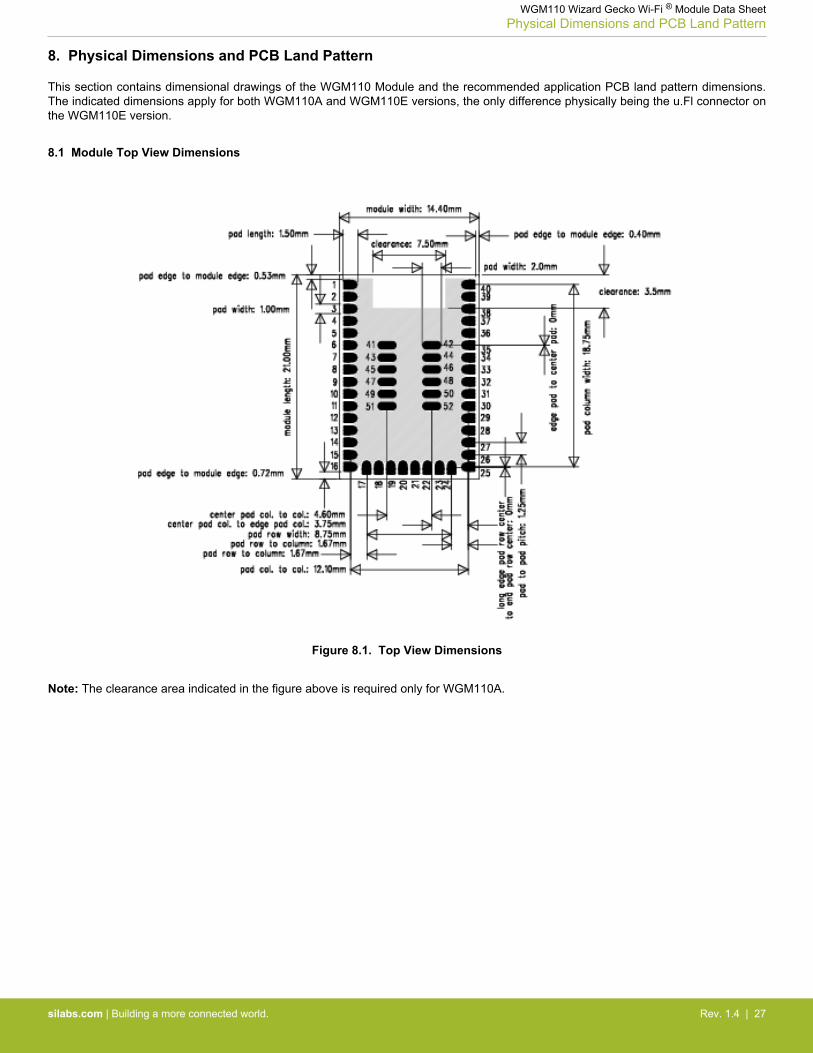
8. Physical Dimensions and PCB Land Pattern
This section contains dimensional drawings of the WGM110 Module and the recommended application PCB land pattern dimensions.The indicated dimensions apply for both WGM110A and WGM110E versions, the only difference physically being the u.Fl connector onthe WGM110E version.
8.1 Module Top View Dimensions
Figure 8.1. Top View Dimensions
Note: The clearance area indicated in the figure above is required only for WGM110A.
WGM110 Wizard Gecko Wi-Fi ® Module Data SheetPhysical Dimensions and PCB Land Pattern
silabs.com | Building a more connected world. Rev. 1.4 | 27
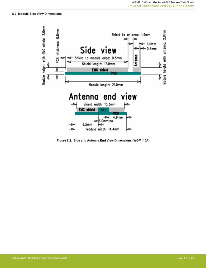
8.2 Module Side View Dimensions
Figure 8.2. Side and Antenna End View Dimensions (WGM110A)
WGM110 Wizard Gecko Wi-Fi ® Module Data SheetPhysical Dimensions and PCB Land Pattern
silabs.com | Building a more connected world. Rev. 1.4 | 28
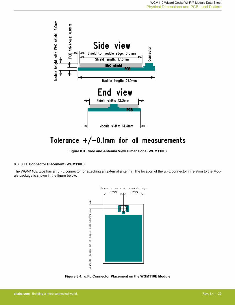
Figure 8.3. Side and Antenna View Dimensions (WGM110E)
8.3 u.FL Connector Placement (WGM110E)
The WGM110E type has an u.FL connector for attaching an external antenna. The location of the u.FL connector in relation to the Mod-ule package is shown in the figure below.
Figure 8.4. u.FL Connector Placement on the WGM110E Module
WGM110 Wizard Gecko Wi-Fi ® Module Data SheetPhysical Dimensions and PCB Land Pattern
silabs.com | Building a more connected world. Rev. 1.4 | 29
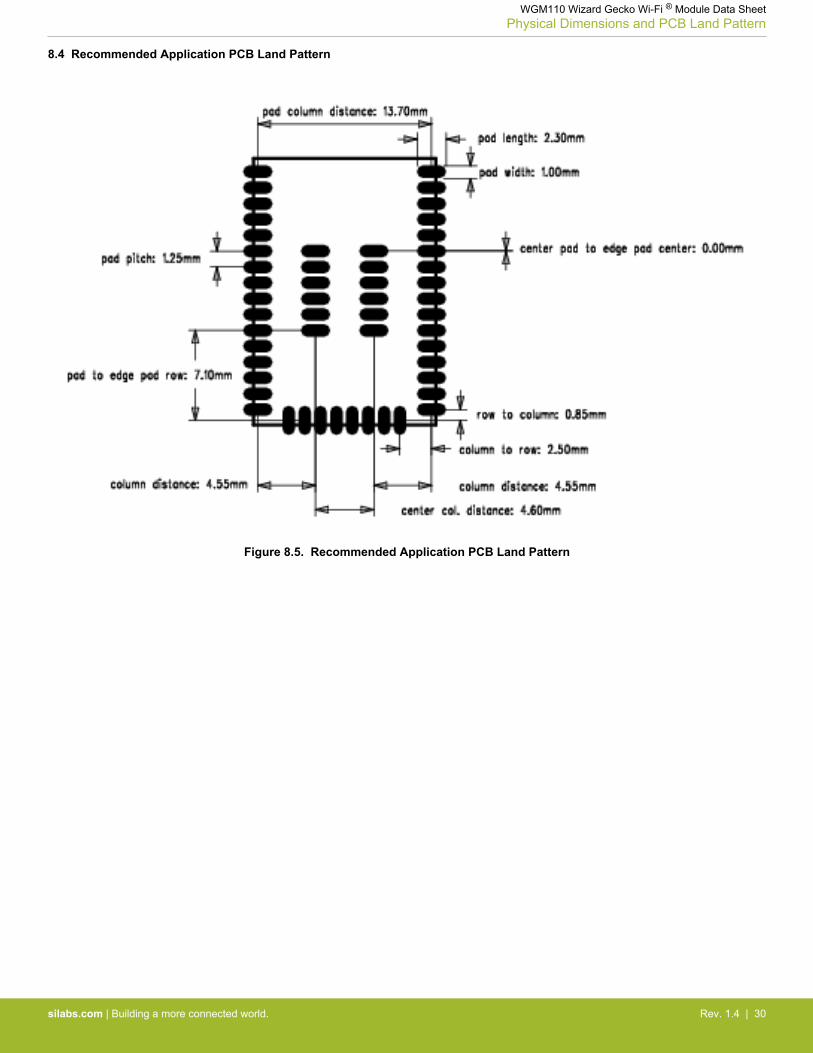
8.4 Recommended Application PCB Land Pattern
Figure 8.5. Recommended Application PCB Land Pattern
WGM110 Wizard Gecko Wi-Fi ® Module Data SheetPhysical Dimensions and PCB Land Pattern
silabs.com | Building a more connected world. Rev. 1.4 | 30

9. Soldering Recommendations
This section describes the soldering recommendations regarding WGM110 Module.
WGM110 is compatible with industrial standard reflow profile for Pb-free solders. The reflow profile used is dependent on the thermalmass of the entire populated PCB, heat transfer efficiency of the oven, and particular type of solder paste used
• Refer to technical documentations of particular solder paste for profile configurations.• Avoid using more than two reflow cycles.• Aperture size of the stencil should be 1:1 with the pad size.• A no-clean, type-3 solder paste is recommended.• For further recommendation, please refer to the JEDEC/IPC J-STD-020, IPC-SM-782 and IPC 7351 guidelines..
WGM110 Wizard Gecko Wi-Fi ® Module Data SheetSoldering Recommendations
silabs.com | Building a more connected world. Rev. 1.4 | 31
10. Tape and Reel Packaging
This section contains information regarding the tape and reel packaging for the Wizard Gecko WGM110 Wi-Fi Module including ship-ment packaging information.
10.1 Tape Material and Dimensions
• Tape material: Polystyrene (PS)• Tape length/reel: 53.4 m• Tape surface resistivity: 104 ... 109 Ω/sq.• Curvature of the tape / 100 mm of tape: Complies with EIA-481 standard• Maximum radius of unmarked round corners: 0.2 mm• Cumulative tolerance of any 10 consecutive sprocket holes: ± 0.2 mm• Cover tape peel strength: The peeling force required to tear the cover tape from the carrier tape will fall within tthe range of 0.1
Newton to 1.3 Newton (10 to 130 grams) at peeling speed to 300 mm per minute. This complies with the EIA standard.• Cover tape adhesion method: pressure sensitive
WGM110 Wizard Gecko Wi-Fi ® Module Data SheetTape and Reel Packaging
silabs.com | Building a more connected world. Rev. 1.4 | 32
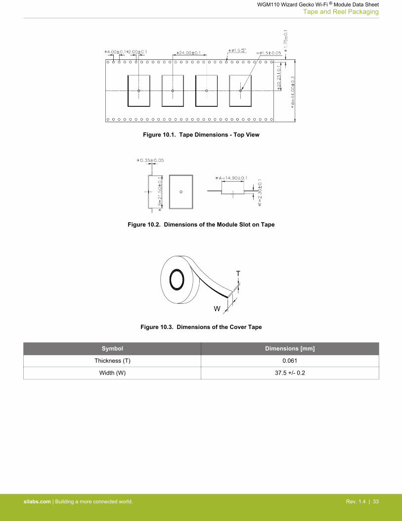
Figure 10.1. Tape Dimensions - Top View
Figure 10.2. Dimensions of the Module Slot on Tape
Figure 10.3. Dimensions of the Cover Tape
Symbol Dimensions [mm]
Thickness (T) 0.061
Width (W) 37.5 +/- 0.2
WGM110 Wizard Gecko Wi-Fi ® Module Data SheetTape and Reel Packaging
silabs.com | Building a more connected world. Rev. 1.4 | 33
10.2 Reel Material and Dimensions
• Reel material: Polystyrene (PS)• Reel diameter: 13 inches (330 mm)• Number of modules per reel: 500 pcs• Environmental standard of reel materials: Delta Management Standard for Environnment related substances• Disk deformation, folding whitening and mold imperfections: Not allowed• Disk set: consists of two 13 inch (330 mm) rotary round disks and one central axis (100 mm)• Antistatic treatment: Required• Surface resistivity: 108 - 1011 Ω/cm2
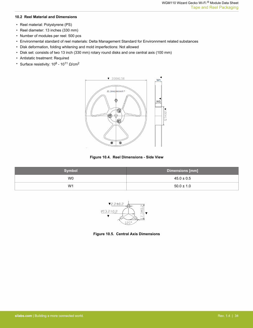
Figure 10.4. Reel Dimensions - Side View
Symbol Dimensions [mm]
W0 45.0 ± 0.5
W1 50.0 ± 1.0
Figure 10.5. Central Axis Dimensions
WGM110 Wizard Gecko Wi-Fi ® Module Data SheetTape and Reel Packaging
silabs.com | Building a more connected world. Rev. 1.4 | 34
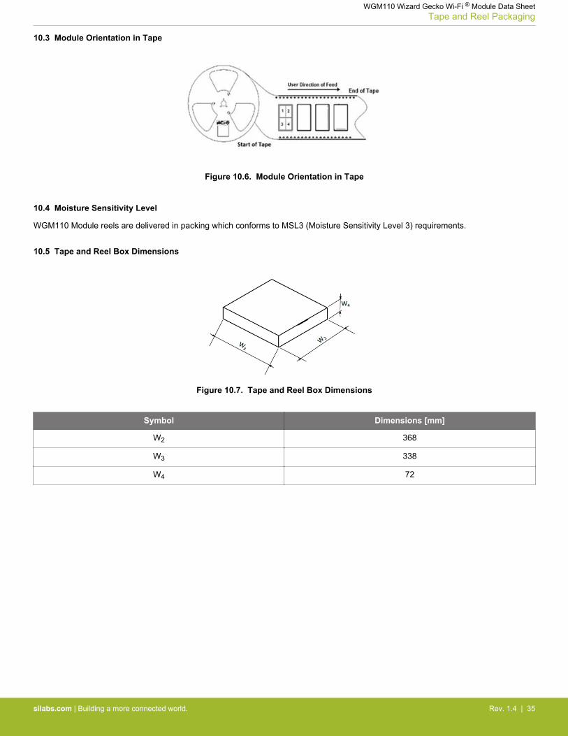
10.3 Module Orientation in Tape
Figure 10.6. Module Orientation in Tape
10.4 Moisture Sensitivity Level
WGM110 Module reels are delivered in packing which conforms to MSL3 (Moisture Sensitivity Level 3) requirements.
10.5 Tape and Reel Box Dimensions
Figure 10.7. Tape and Reel Box Dimensions
Symbol Dimensions [mm]
W2 368
W3 338
W4 72
WGM110 Wizard Gecko Wi-Fi ® Module Data SheetTape and Reel Packaging
silabs.com | Building a more connected world. Rev. 1.4 | 35

11. Certifications
The certifications for the WGM110 Wi-Fi Module are listed in this section.
11.1 CE
The WGM110 Module is in conformity with the essential requirements and other relevant requirements of the R&TTE Directive (1999/5/EC). This device is compliant with the following standards:• Safety: EN 60950• EMC: EN 301 489• Spectrum: EN 300 328
A formal DoC is available from www.silabs.com.
11.2 FCC
This device complies with Part 15 of the FCC Rules. Operation is subject to the following two conditions:1. This device may not cause harmful interference, and2. This device must accept any interference received, including interference that may cause undesirable operation.
Any changes or modifications not expressly approved by Silicon Labs could void the user’s authority to operate the equipment.
FCC RF Radiation Exposure Statement:
This equipment complies with FCC radiation exposure limits set forth for an uncontrolled environment. End users must follow the specif-ic operating instructions for satisfying RF exposure compliance. This transmittermeets both portable and mobile limits as demonstratedin the RF Exposure Analysis. This transmitter must not be co-located or operating in conjunction with any other antenna or transmitterexcept in accordance with FCC multi-transmitter product procedures. As long as the condition above is met, further transmitter testingwill not be required. However, the OEM integrator is still responsible for testing their end-product for any additional compliance require-ments required with this module installed (for example, digital device emissions, PC peripheral requirements, etc.).
OEM Responsibilities to comply with FCC Regulations
The WGM110 Module has been certified for integration into products only by OEM integrators under the following condition:• The antenna(s) must be installed such that a minimum separation distance of 21 mm (WGM110A and WGM110E) is maintained
between the radiator (antenna) and all persons at all times.• The transmitter module must not be co-located or operating in conjunction with any other antenna or transmitter except in accord-
ance with FCC multi-transmitter product procedures.
WGM110 Wizard Gecko Wi-Fi ® Module Data SheetCertifications
silabs.com | Building a more connected world. Rev. 1.4 | 36

As long as the conditions above are met, further transmitter testing will not be required. However, the OEM integrator is still responsiblefor testing their end-product for any additional compliance requirements required with this module installed (for example, digital deviceemissions, PC peripheral requirements, etc.).
Note: In the event that this condition cannot be met (for certain configurations or co-location with another transmitter), then the FCCauthorization is no longer considered valid and the FCC ID cannot be used on the final product. In these circumstances, the OEM inte-grator will be responsible for re-evaluating the end product (including the transmitter) and obtaining a separate FCC authorization.
End Product Labeling
The WGM110 Module is labeled with its own FCC ID. If the FCC ID is not visible when the module is installed inside another device,then the outside of the device into which the module is installed must also display a label referring to the enclosed module. In that case,the final end product must be labeled in a visible area with the following:
"Contains Transmitter Module FCC ID: QOQ-WGM110"
or
"Contains FCC ID: QOQ-WGM110"
The OEM integrator must not provide information to the end user regarding how to install or remove this RF module or change RFrelated parameters in the user manual of the end product.
To comply with FCC RF radiation exposure limits for general population, the antenna(s) used for this transmitter must be in-stalled such that a minimum separation distance of 21 mm (WGM110A and WGM110E) is maintained between the radiator(antenna) and all persons at all times and must not be co-located or operating in conjunction with any other antenna or trans-mitter.
WGM110 Wizard Gecko Wi-Fi ® Module Data SheetCertifications
silabs.com | Building a more connected world. Rev. 1.4 | 37

11.3 IC
IC (English)
This radio transmitter has been approved by Industry Canada to operate with the embedded chip antenna. Other antenna types arestrictly prohibited for use with this device.
This device complies with Industry Canada’s license-exempt RSS standards. Operation is subject to the following two conditions:1. This device may not cause interference; and2. This device must accept any interference, including interference that may cause undesired operation of the device.
RF Exposure Statement
Exception from routine SAR evaluation limits are given in RSS-102 Issue 5. WGM110A meets the given requirements when the mini-mum separation distance to human body 25 mm and WGM110E when the minimum separation distance to human body is 30 mm. RFexposure or SAR evaluation is not required when the separation distance is 25 mm (WGM110A) / 30 mm (WGM110E) or more. If theseparation distance is less than 25 mm (WGM110A) / 30 mm (WGM110E) the OEM integrator is responsible for evaluating the SAR.
OEM Responsibilities to comply with IC Regulations
The WGM110 Module has been certified for integration into products only by OEM integrators under the following conditions:• The antenna(s) must be installed such that a minimum separation distance of 25 mm (WGM110A) / 30 mm (WGM110E) is main-
tained between the radiator (antenna) and all persons at all times.• The transmitter module must not be co-located or operating in conjunction with any other antenna or transmitter.
As long as the two conditions above are met, further transmitter testing will not be required. However, the OEM integrator is still respon-sible for testing their end-product for any additional compliance requirements required with this module installed (for example, digitaldevice emissions, PC peripheral requirements, etc.).
Note: In the event that these conditions cannot be met (for certain configurations or co-location with another transmitter), then the ICauthorization is no longer considered valid and the IC ID cannot be used on the final product. In these circumstances, the OEM integra-tor will be responsible for re-evaluating the end product (including the transmitter) and obtaining a separate IC authorization.
End Product Labeling
The WGM110 Module is labeled with its own IC ID. If the IC ID is not visible when the module is installed inside another device, thenthe outside of the device into which the module is installed must also display a label referring to the enclosed module. In that case, thefinal end product must be labeled in a visible area with the following:
"Contains Transmitter Module IC: 5123A-WGM110"
or
"Contains IC: 5123A-WGM110"
The OEM integrator has to be aware not to provide information to the end user regarding how to install or remove this RF module orchange RF related parameters in the user manual of the end product.
IC (Francais)
Cet émetteur radio (IC : 5123A-WGM110) a reçu l'approbation d'Industrie Canada pour une exploitation avec l'antenne puce incorpo-rée. Il est strictement interdit d'utiliser d'autres types d'antenne avec cet appareil.
Le présent appareil est conforme aux CNR d’Industrie Canada applicables aux appareils radio exempts de licence. L’exploitation estautorisée aux deux conditions suivantes:
1. L’appareil ne doit pas produire de brouillage;2. L’utilisateur de l’appareil doit accepter tout brouillage radioélectrique subi, même si le brouillage est susceptible d’en compromettre
le fonctionnement.
Déclaration relative à l'exposition aux radiofréquences (RF)
Les limites applicables à l’exemption de l’évaluation courante du DAS sont énoncées dans le CNR 102, 5e édition. L'appareil WGM110répond aux exigences données quand la distance de séparation minimum par rapport au corps humain est inférieure ou égale à 25 mm(WGM110A) / 30 mm (WGM110E). L'évaluation de l'exposition aux RF ou du DAS n'est pas requise quand la distance de séparationest de 25 mm ou plus (WGM110A) / 30 mm ou plus (WGM110E). Si la distance de séparation est inférieure à 25 mm (WGM110A) / 30mm (WGM110E), il incombe à l'intégrateur FEO d'évaluer le DAS.
Responsabilités du FEO ayant trait à la conformité avec les règlements IC
WGM110 Wizard Gecko Wi-Fi ® Module Data SheetCertifications
silabs.com | Building a more connected world. Rev. 1.4 | 38
Le Module WGM110 a été certifié pour une intégration dans des produits uniquement par les intégrateurs FEO dans les conditionssuivantes:• La ou les antennes doivent être installées de telle façon qu'une distance de séparation minimum de 25 mm (WGM110A) / 30 mm
(WGM110E) (soit maintenue entre le radiateur (antenne) et toute personne à tout moment.• Le module émetteur ne doit pas être installé au même endroit ou fonctionner conjointement avec toute autre antenne ou émetteur.
Dès lors que les deux conditions ci-dessus sont respectées, d'autres tests de l'émetteur ne sont pas obligatoires. Cependant, il in-combe toujours à l'intégrateur FEO de tester la conformité de son produit final vis-à-vis de toute exigence supplémentaire avec ce mod-ule installé (par exemple, émissions de dispositifs numériques, exigences relatives aux matériels périphériques PC, etc).
Note: S'il s'avère que ces conditions ne peuvent être respectées (pour certaines configurations ou la colocation avec un autre émet-teur), alors l'autorisation IC n'est plus considérée comme valide et l'identifiant IC ne peut plus être employé sur le produit final. Dansces circonstances, l'intégrateur FEO aura la responsabilité de réévaluer le produit final (y compris l'émetteur) et d'obtenir une autorisa-tion IC distincte.
Étiquetage du produit final
L'étiquette du Module WGM110 porte son propre identifiant IC. Si l'identifiant IC n'est pas visible quand le module est installé à l'intér-ieur d'un autre appareil, l'extérieur de l'appareil dans lequel le module est installé doit aussi porter une étiquette faisant référence aumodule qu'il contient. Dans ce cas, une étiquette comportant les informations suivantes doit être collée sur une partie visible du produitfinal.
"Contient le module émetteur IC: 5123A-WGM110"
or
"Contient IC : 5123A-WGM110"
L'intégrateur FEO doit être conscient de ne pas fournir d'informations à l'utilisateur final permettant d'installer ou de retirer ce moduleRF ou de changer les paramètres liés aux RF dans le mode d'emploi du produit final.
11.4 MIC Japan
The WGM110 Module is certified for Japan.
Certification number: 209-J00197.
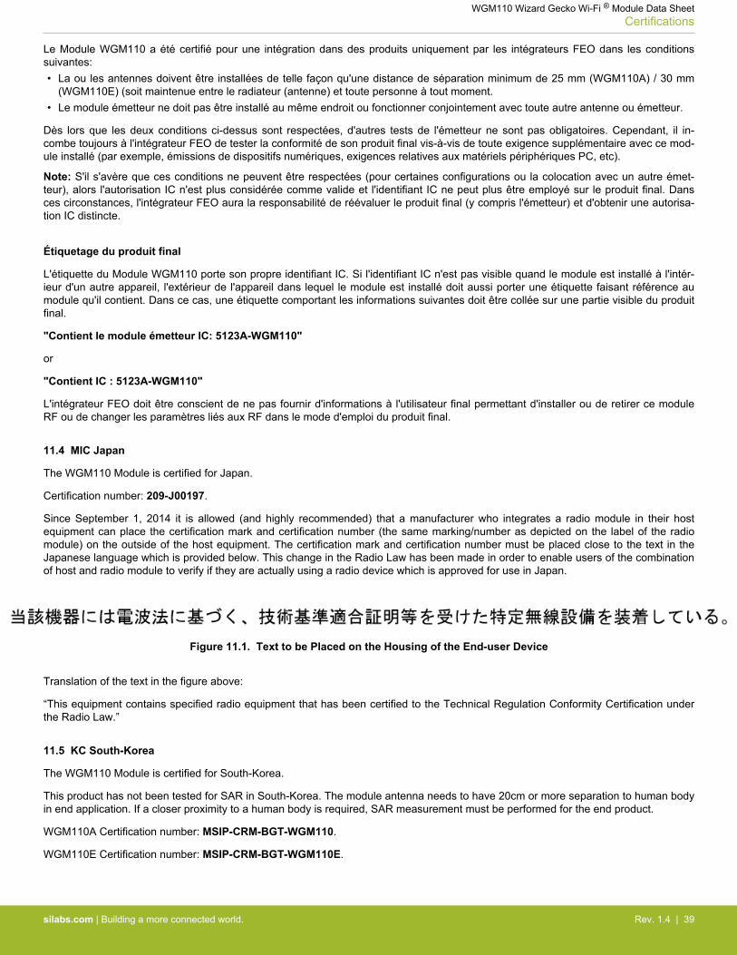
Since September 1, 2014 it is allowed (and highly recommended) that a manufacturer who integrates a radio module in their hostequipment can place the certification mark and certification number (the same marking/number as depicted on the label of the radiomodule) on the outside of the host equipment. The certification mark and certification number must be placed close to the text in theJapanese language which is provided below. This change in the Radio Law has been made in order to enable users of the combinationof host and radio module to verify if they are actually using a radio device which is approved for use in Japan.
Figure 11.1. Text to be Placed on the Housing of the End-user Device
Translation of the text in the figure above:
“This equipment contains specified radio equipment that has been certified to the Technical Regulation Conformity Certification underthe Radio Law.”
11.5 KC South-Korea
The WGM110 Module is certified for South-Korea.
This product has not been tested for SAR in South-Korea. The module antenna needs to have 20cm or more separation to human bodyin end application. If a closer proximity to a human body is required, SAR measurement must be performed for the end product.
WGM110A Certification number: MSIP-CRM-BGT-WGM110.
WGM110E Certification number: MSIP-CRM-BGT-WGM110E.
WGM110 Wizard Gecko Wi-Fi ® Module Data SheetCertifications
silabs.com | Building a more connected world. Rev. 1.4 | 39
12. Ordering Information
This section contains cut reel (100 pcs) and full reel (500 pcs) ordering information for WGM110 Module. WGM110 Module offer aWGM110A version with integrated antenna and WGM110E version with an U.FL external antenna connector.
WGM110A1MV2 (orderable part number / cut reel) and WGM110A1MV2R (orderable part number / full reel) are the product codes forthe full production (certified) version of the WGM110 Wizard Gecko Wi-Fi™ Module. The certification codes are printed on the metallicRF shield of the WGM110 Module.
WGM110A1MV1 (cut reel) and WGM110A1MV1 (full reel) are the product codes for the pre-production (non-certified) version of theModule. The only difference of the the V1 and V2 Module versions is the certification markings on the shield of the V2 version.
Note: The only visual difference between pre-production and production Module versions are the certification codes printed on the RFshield.
Silicon Labs reserves the right to deliver WGM110A1MV2 or WGM110A1MV2R (production version) for customers orderingWGM110A1MV1 (pre-production version) and WGM110E1MV2 or WGM110E1MV2R (production version) for customers orderingWGM110E1MV1 (pre-production version).
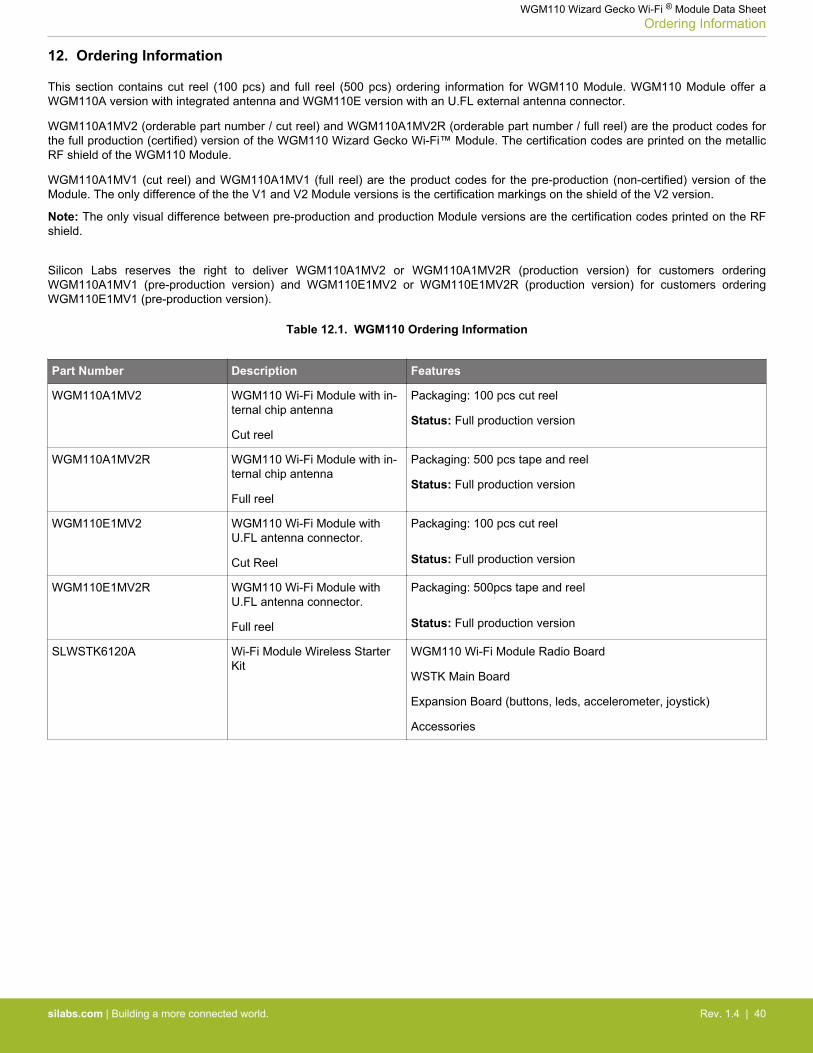
Table 12.1. WGM110 Ordering Information
Part Number Description Features
WGM110A1MV2 WGM110 Wi-Fi Module with in-ternal chip antenna
Cut reel
Packaging: 100 pcs cut reel
Status: Full production version
WGM110A1MV2R WGM110 Wi-Fi Module with in-ternal chip antenna
Full reel
Packaging: 500 pcs tape and reel
Status: Full production version
WGM110E1MV2 WGM110 Wi-Fi Module withU.FL antenna connector.
Cut Reel
Packaging: 100 pcs cut reel
Status: Full production version
WGM110E1MV2R WGM110 Wi-Fi Module withU.FL antenna connector.
Full reel
Packaging: 500pcs tape and reel
Status: Full production version
SLWSTK6120A Wi-Fi Module Wireless StarterKit
WGM110 Wi-Fi Module Radio Board
WSTK Main Board
Expansion Board (buttons, leds, accelerometer, joystick)
Accessories
WGM110 Wizard Gecko Wi-Fi ® Module Data SheetOrdering Information
silabs.com | Building a more connected world. Rev. 1.4 | 40

13. Support
This section lists the available support provided by Silicon Labs for the WGM110 Module.
13.1 Device Support
Silicon Labs provides support material to help test, evaluate, and program the WGM110 Module. The following sub-section describesthe Wireless Starter Kit WSTK6120A in more detail.
13.1.1 Wireless Starter Kit WSTK6120A
Silicon Labs Wireless Starter Kit WSTK6120A provides a platform which enables easy testing and programming of the WGM110 Mod-ule. The kit includes the WSTK Mainboard, the BRD4320A Radio Board with the WGM110 Module installed on it and an Add-On BoardBRD8006A, an external battery holder for 2x AA batteries, and USB cables.
The WGM110 Module on the Radio Board has firmware which includes a demo software. The WSTK kit provides the easiest and mostrecommendable way of getting started on application development using the WGM110 Module.
13.2 Documentation Support
Silicon Labs offers a set of documents which provide further information required for developing applications bases on the WGM110Module. These documents are available in the web from the Silicon Labs Document Library nd include the following:
• UG172: Wizard Gecko Wi-Fi® Module Wireless Starter Kit SLWSTK6120A User's Guide• Wizard Gecko WGM110 Wi-Fi® Module Radio Board BRD4320A Reference Manual• QSG119: Wizard Gecko WSTK Quick-Start Guide• AN967: Wizard Gecko WSTK Demo Walkthrough• UG160: Wizard Gecko BGTool™ User's Guide• UG170: Wizard Gecko BGScript™ User's Guide• UG161: WGM110 Wi-Fi® Module Configuration User's Guide• QSG122: WGM110 Wi-Fi® Module Software Quick-Start Guide• WGM110 API Reference Manual
13.3 Knowledge Base
Silicon Labs provides an online knowledge base on its web site offering an efficient way of exchanging user experience and enablingthe presentation of both questions and solutions to all registered users.
The link to the knowledge base is www.silabs.com/support/knowledgebase.
13.4 Technical Support
If you need further assistance and can not find the answer from the Silicon Labs' Knowledgebase you can contact Silicon Labs Techni-cal Support through a web page.
Technical Support web link: www.silabs.com/support/
WGM110 Wizard Gecko Wi-Fi ® Module Data SheetSupport
silabs.com | Building a more connected world. Rev. 1.4 | 41
14. Revision History
14.1 Revision 1.4
March 31st, 2017
Wi-Fi Direct included.
14.2 Revision 1.3
October 26th, 2016
Soldering recommendation, module tape cover and orientation picture graphics updated.
14.3 Revision 1.2
August 30th, 2016
Added WGM110E variant information.
14.4 Revision 1.1
May 12, 2016
This revision is published with the release of the full production version of the WGM110 Wizard Gecko Wi-Fi™ Module.
Changes: Added support for IP multicast, power consumption values updated, SPI support information updated, power supply require-ments clarified, Ground plane width guideline updated, Japan and Korea certification numbers added.
14.5 Revision 1.0
April 31, 2016
This revision is published with the release of the pre-production version of the WGM110 Wizard Gecko Wi-Fi™ Module.
First release.
WGM110 Wizard Gecko Wi-Fi ® Module Data SheetRevision History
silabs.com | Building a more connected world. Rev. 1.4 | 42

http://www.silabs.com
Silicon Laboratories Inc.400 West Cesar ChavezAustin, TX 78701USA
Smart. Connected. Energy-Friendly.
Productswww.silabs.com/products
Qualitywww.silabs.com/quality
Support and Communitycommunity.silabs.com
DisclaimerSilicon Labs intends to provide customers with the latest, accurate, and in-depth documentation of all peripherals and modules available for system and software implementers using or intending to use the Silicon Labs products. Characterization data, available modules and peripherals, memory sizes and memory addresses refer to each specific device, and "Typical" parameters provided can and do vary in different applications. Application examples described herein are for illustrative purposes only. Silicon Labs reserves the right to make changes without further notice and limitation to product information, specifications, and descriptions herein, and does not give warranties as to the accuracy or completeness of the included information. Silicon Labs shall have no liability for the consequences of use of the information supplied herein. This document does not imply or express copyright licenses granted hereunder to design or fabricate any integrated circuits. The products are not designed or authorized to be used within any Life Support System without the specific written consent of Silicon Labs. A "Life Support System" is any product or system intended to support or sustain life and/or health, which, if it fails, can be reasonably expected to result in significant personal injury or death. Silicon Labs products are not designed or authorized for military applications. Silicon Labs products shall under no circumstances be used in weapons of mass destruction including (but not limited to) nuclear, biological or chemical weapons, or missiles capable of delivering such weapons.
Trademark InformationSilicon Laboratories Inc.® , Silicon Laboratories®, Silicon Labs®, SiLabs® and the Silicon Labs logo®, Bluegiga®, Bluegiga Logo®, Clockbuilder®, CMEMS®, DSPLL®, EFM®, EFM32®, EFR, Ember®, Energy Micro, Energy Micro logo and combinations thereof, "the world’s most energy friendly microcontrollers", Ember®, EZLink®, EZRadio®, EZRadioPRO®, Gecko®, ISOmodem®, Precision32®, ProSLIC®, Simplicity Studio®, SiPHY®, Telegesis, the Telegesis Logo®, USBXpress® and others are trademarks or registered trademarks of Silicon Labs. ARM, CORTEX, Cortex-M3 and THUMB are trademarks or registered trademarks of ARM Holdings. Keil is a registered trademark of ARM Limited. All other products or brand names mentioned herein are trademarks of their respective holders.