Embed Size (px)
Citation preview
JOB AID Part No. 4317269
WHIRLPOOL & KITCHENAIDBUILT-IN ELECTRIC
COOKTOPS
- ii -
WHIRLPOOL CORPORATION assumes no responsibility for any repairmade on our products by anyone other than Authorized Factory ServiceTechnicians.
Copyright 1999, Whirlpool Corporation, Benton Harbor, MI 49022
FORWARDThis Job Aid, “Whirlpool & KitchenAid Built-In Electric Cooktops,” (Part No. 4317269), providesthe technician with information on the installation and service of Whirlpool & KitchenAid Built-InElectric Cooktops. It is to be used as a training Job Aid and Service Manual. For specific informa-tion on the model being serviced, refer to the “Use and Care Guide,” or “Tech Sheet” providedwith the cooktop.
The Wiring Diagrams used in this Job Aid are typical and should be used for training purposesonly. Always use the Wiring Diagram supplied with the product when servicing the unit.
GOALS AND OBJECTIVESThe goal of this Job Aid is to provide detailed information that will enable the service technician toproperly diagnose malfunctions and repair Built-In Electric Cooktops.
The objectives of this Job Aid are to:
• Understand and follow proper safety precautions.
• Successfully troubleshoot and diagnose malfunctions.
• Successfully perform necessary repairs.
• Successfully return the cooktop to proper operational status.
- iii -
Table of Contents
SPECIFICATIONS .................................................................................................................. 1-1
INSTALLATION HIGHLIGHTS................................................................................................ 2-1Electrical Requirements ..................................................................................................... 2-1Electrical Connections ....................................................................................................... 2-2Installation.......................................................................................................................... 2-4
COMPONENT ACCESS ......................................................................................................... 3-1Component Locations ........................................................................................................ 3-1Removing The Maintop...................................................................................................... 3-2Removing The Indicator Light, An Element Control, A Coil Receptacle, & The T.O.D. .................................................................................... 3-4Removing The Ceramic Glass Maintop ............................................................................. 3-6
COMPONENT TESTING ........................................................................................................ 4-1
WIRING DIAGRAMS............................................................................................................... 5-1
TECH TIPS ............................................................................................................................. 6-1
PAGE
- iv -
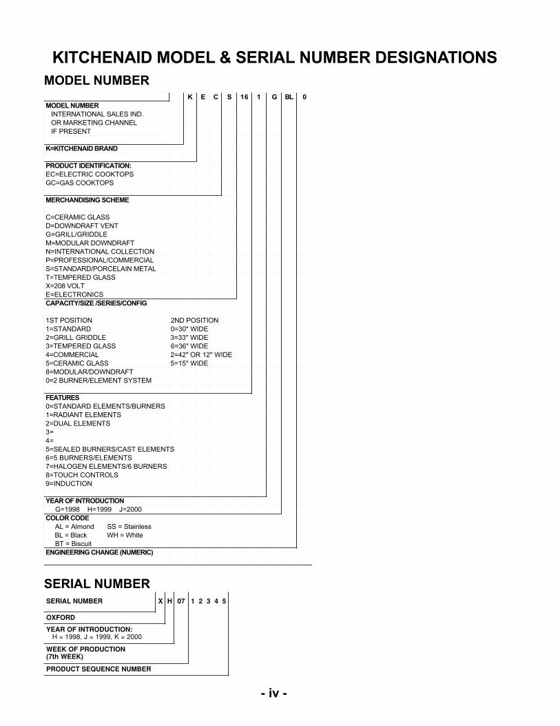
KITCHENAID MODEL & SERIAL NUMBER DESIGNATIONS
K E C S 16 1 G BL 0
MODEL NUMBER
INTERNATIONAL SALES IND.
OR MARKETING CHANNEL
IF PRESENT
K=KITCHENAID BRAND
PRODUCT IDENTIFICATION:
EC=ELECTRIC COOKTOPS
GC=GAS COOKTOPS
MERCHANDISING SCHEME
C=CERAMIC GLASS
D=DOWNDRAFT VENT
G=GRILL/GRIDDLE
M=MODULAR DOWNDRAFT
N=INTERNATIONAL COLLECTION
P=PROFESSIONAL/COMMERCIAL
S=STANDARD/PORCELAIN METAL
T=TEMPERED GLASS
X=208 VOLT
E=ELECTRONICS
CAPACITY/SIZE /SERIES/CONFIG
1ST POSITION 2ND POSITION
1=STANDARD 0=30" WIDE
2=GRILL GRIDDLE 3=33" WIDE
3=TEMPERED GLASS 6=36" WIDE
4=COMMERCIAL 2=42" OR 12" WIDE
5=CERAMIC GLASS 5=15" WIDE
8=MODULAR/DOWNDRAFT
0=2 BURNER/ELEMENT SYSTEM
FEATURES
0=STANDARD ELEMENTS/BURNERS
1=RADIANT ELEMENTS
2=DUAL ELEMENTS
3=
4=
5=SEALED BURNERS/CAST ELEMENTS
6=5 BURNERS/ELEMENTS
7=HALOGEN ELEMENTS/6 BURNERS
8=TOUCH CONTROLS
9=INDUCTION
YEAR OF INTRODUCTION
G=1998 H=1999 J=2000
COLOR CODE
AL = Almond SS = Stainless
BL = Black WH = White
BT = Biscuit
ENGINEERING CHANGE (NUMERIC)
MODEL NUMBER
SERIAL NUMBER
SERIAL NUMBER X H 07 1 2 3 4 5
OXFORD
YEAR OF INTRODUCTION: H = 1998, J = 1999, K = 2000
WEEK OF PRODUCTION(7th WEEK)
PRODUCT SEQUENCE NUMBER
- v -
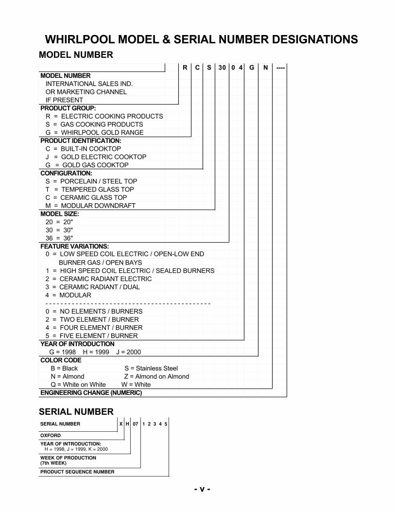
WHIRLPOOL MODEL & SERIAL NUMBER DESIGNATIONS
SERIAL NUMBER
SERIAL NUMBER X H 07 1 2 3 4 5
OXFORD
YEAR OF INTRODUCTION: H = 1998, J = 1999, K = 2000
WEEK OF PRODUCTION(7th WEEK)
PRODUCT SEQUENCE NUMBER
MODEL NUMBER
R C S 30 0 4 G N ----
MODEL NUMBER
INTERNATIONAL SALES IND.
OR MARKETING CHANNEL
IF PRESENT
PRODUCT GROUP:
R = ELECTRIC COOKING PRODUCTS
S = GAS COOKING PRODUCTS
G = WHIRLPOOL GOLD RANGE
PRODUCT IDENTIFICATION:
C = BUILT-IN COOKTOP
J = GOLD ELECTRIC COOKTOP
G = GOLD GAS COOKTOP
CONFIGURATION:
S = PORCELAIN / STEEL TOP
T = TEMPERED GLASS TOP
C = CERAMIC GLASS TOP
M = MODULAR DOWNDRAFT
MODEL SIZE:
20 = 20"
30 = 30"
36 = 36"
FEATURE VARIATIONS: 0 = LOW SPEED COIL ELECTRIC / OPEN-LOW END
BURNER GAS / OPEN BAYS
1 = HIGH SPEED COIL ELECTRIC / SEALED BURNERS
2 = CERAMIC RADIANT ELECTRIC
3 = CERAMIC RADIANT / DUAL
4 = MODULAR
- - - - - - - - - - - - - - - - - - - - - - - - - - - - - - - - - - - - - - - - - - - -
0 = NO ELEMENTS / BURNERS
2 = TWO ELEMENT / BURNER
4 = FOUR ELEMENT / BURNER
5 = FIVE ELEMENT / BURNER
YEAR OF INTRODUCTION
G = 1998 H = 1999 J = 2000
COLOR CODE
B = Black S = Stainless Steel
N = Almond Z = Almond on Almond
Q = White on White W = White
ENGINEERING CHANGE (NUMERIC)
- vi -
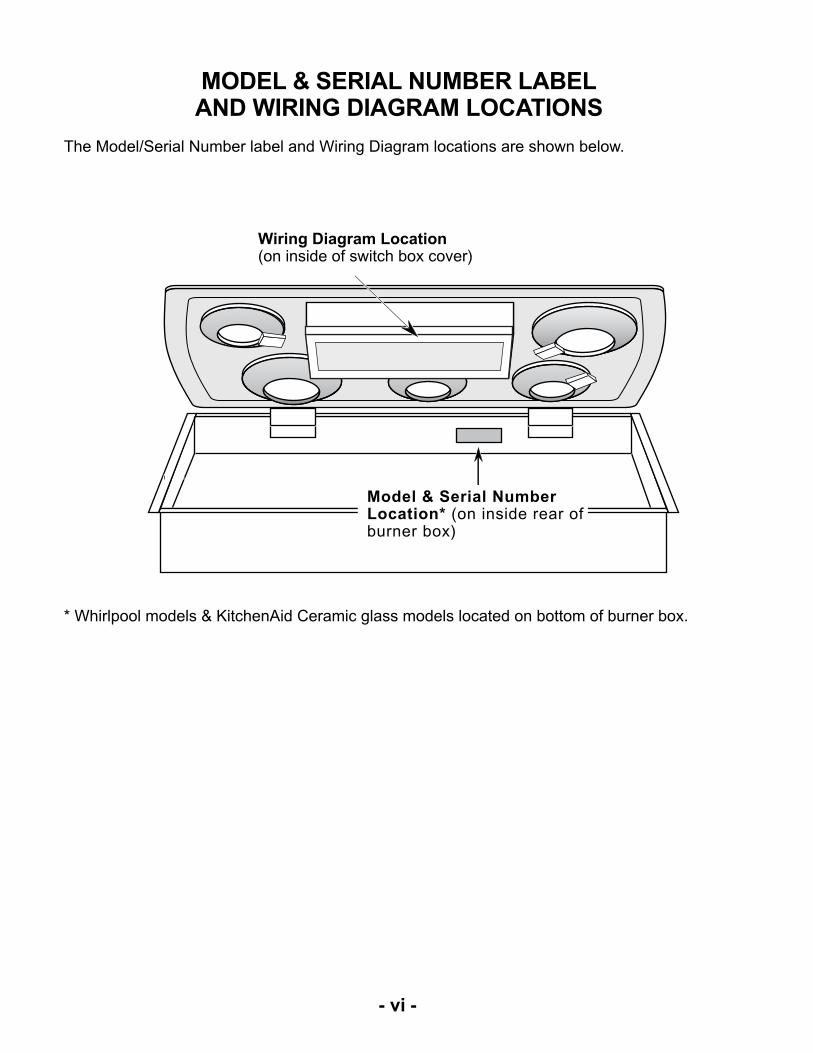
MODEL & SERIAL NUMBER LABELAND WIRING DIAGRAM LOCATIONS
The Model/Serial Number label and Wiring Diagram locations are shown below.
Wiring Diagram Location(on inside of switch box cover)
Model & Serial NumberLocation* (on inside rear ofburner box)
* Whirlpool models & KitchenAid Ceramic glass models located on bottom of burner box.
- vii -
IMPORTANT SAFETY INFORMATION
Your safety and the safety of others is very important.Important safety messages have been provided in this Job Aid. Always read and obey allsafety messages.
This is the safety alert symbol.
This symbol alerts you to hazards that can kill or hurt you and others.
All safety messages will be preceded by the safety alert symbol and the word “WARNING.”
All safety messages will identify the hazard, tell you how to reduce the chance of injury, and tellyou what can happen if the instructions are not followed.

- viii -
— NOTES —
1-1
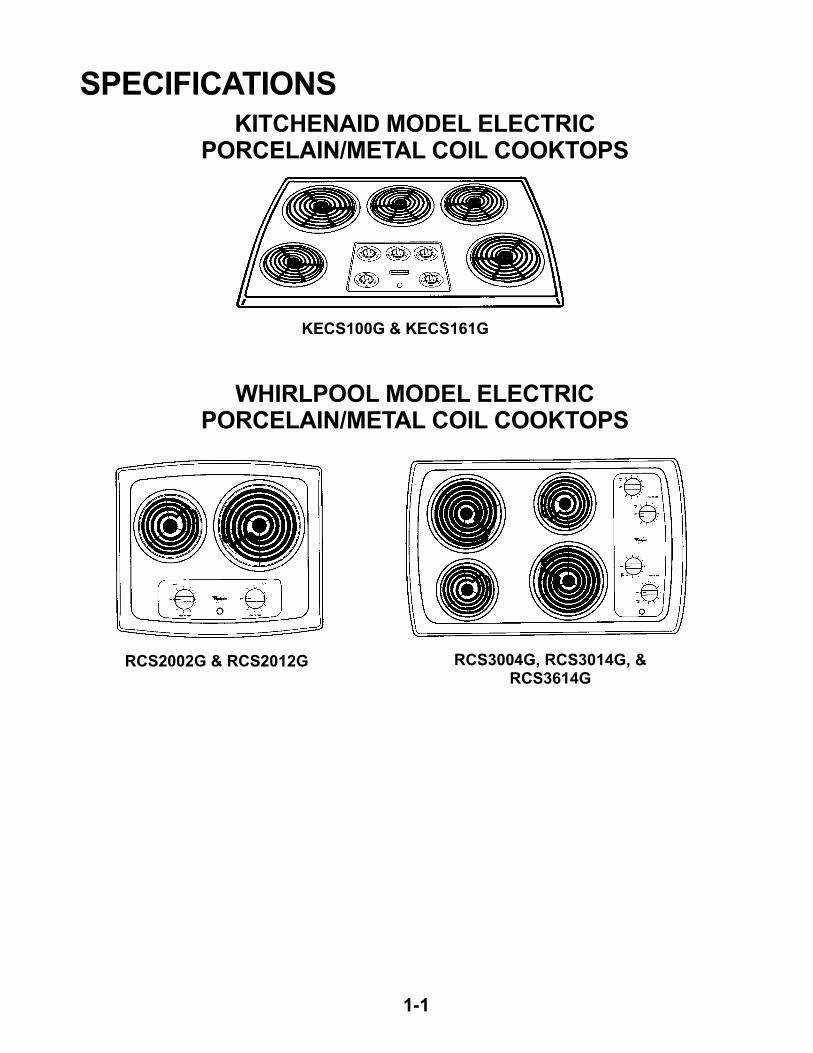
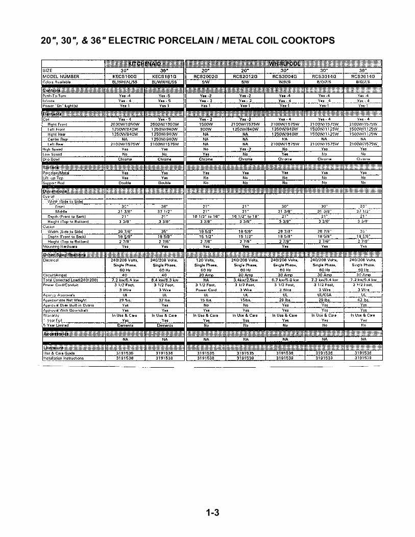
SPECIFICATIONSKITCHENAID MODEL ELECTRIC
PORCELAIN/METAL COIL COOKTOPS
WHIRLPOOL MODEL ELECTRICPORCELAIN/METAL COIL COOKTOPS
KECS100G & KECS161G
RCS2002G & RCS2012G RCS3004G, RCS3014G, &RCS3614G

1-2
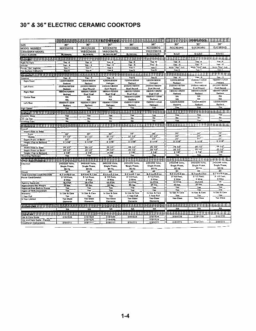
KITCHENAID MODEL ELECTRIC CERAMIC COOKTOPS
WHIRLPOOL MODEL ELECTRIC CERAMIC COOKTOPS
KECC501G, KECC502G,YKECC502G, KECC507G, &
YKECC507G
KECC562G, KECC567G &YKECC567G
RCC3024G, GJC3034G, &GJC3634G
1-3
20", 30", & 36" ELECTRIC PORCELAIN / METAL COIL COOKTOPS
1-4
30" & 36" ELECTRIC CERAMIC COOKTOPS
2-1
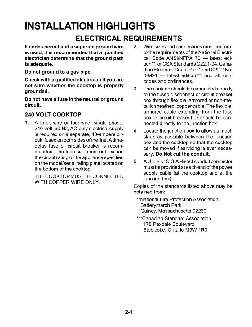
If codes permit and a separate ground wireis used, it is recommended that a qualifiedelectrician determine that the ground pathis adequate.
Do not ground to a gas pipe.
Check with a qualified electrician if you arenot sure whether the cooktop is properlygrounded.
Do not have a fuse in the neutral or groundcircuit.
240 VOLT COOKTOP
1. A three-wire or four-wire, single phase,240-volt, 60-Hz, AC-only electrical supplyis required on a separate, 40-ampere cir-cuit, fused on both sides of the line. A time-delay fuse or circuit breaker is recom-mended. The fuse size must not exceedthe circuit rating of the appliance specifiedon the model/serial rating plate located onthe bottom of the cooktop.
THE COOKTOP MUST BE CONNECTEDWITH COPPER WIRE ONLY.
INSTALLATION HIGHLIGHTSELECTRICAL REQUIREMENTS
2. Wire sizes and connections must conformto the requirements of the National Electri-cal Code ANSI/NFPA 70 — latest edi-tion**, or CSA Standards C22.1-94, Cana-dian Electrical Code, Part 1 and C22.2 No.0-M91 — latest edition*** and all localcodes and ordinances.
3. The cooktop should be connected directlyto the fused disconnect or circuit breakerbox through flexible, armored or non-me-tallic sheathed, copper cable. The flexible,armored cable extending from the fusebox or circuit breaker box should be con-nected directly to the junction box.
4. Locate the junction box to allow as muchslack as possible between the junctionbox and the cooktop so that the cooktopcan be moved if servicing is ever neces-sary. Do Not cut the conduit.
5. A U.L. - or C.S.A.-listed conduit connectormust be provided at each end of the powersupply cable (at the cooktop and at thejunction box).
Copies of the standards listed above may beobtained from:
**National Fire Protection Association Batterymarch Park Quincy, Massachusetts 02269
***Canadian Standard Association 178 Rexdale Boulevard Etobicoke, Ontario M9W 1R3
2-2
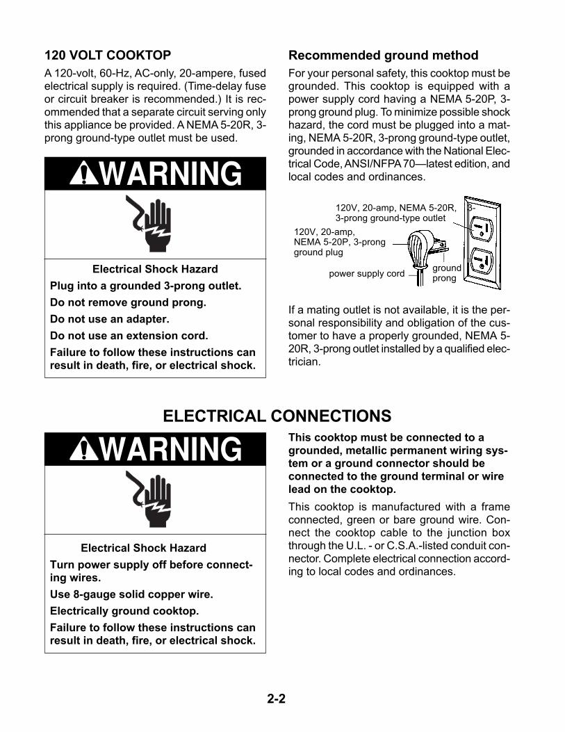
Electrical Shock Hazard
Plug into a grounded 3-prong outlet.
Do not remove ground prong.
Do not use an adapter.
Do not use an extension cord.
Failure to follow these instructions canresult in death, fire, or electrical shock.
120 VOLT COOKTOP
A 120-volt, 60-Hz, AC-only, 20-ampere, fusedelectrical supply is required. (Time-delay fuseor circuit breaker is recommended.) It is rec-ommended that a separate circuit serving onlythis appliance be provided. A NEMA 5-20R, 3-prong ground-type outlet must be used.
WARNING
Recommended ground method
For your personal safety, this cooktop must begrounded. This cooktop is equipped with apower supply cord having a NEMA 5-20P, 3-prong ground plug. To minimize possible shockhazard, the cord must be plugged into a mat-ing, NEMA 5-20R, 3-prong ground-type outlet,grounded in accordance with the National Elec-trical Code, ANSI/NFPA 70—latest edition, andlocal codes and ordinances.
This cooktop must be connected to agrounded, metallic permanent wiring sys-tem or a ground connector should beconnected to the ground terminal or wirelead on the cooktop.
This cooktop is manufactured with a frameconnected, green or bare ground wire. Con-nect the cooktop cable to the junction boxthrough the U.L. - or C.S.A.-listed conduit con-nector. Complete electrical connection accord-ing to local codes and ordinances.
WARNING
120V, 20-amp, NEMA 5-20R, 3-3-prong ground-type outlet
120V, 20-amp,NEMA 5-20P, 3-prongground plug
power supply cord
Electrical Shock Hazard
Turn power supply off before connect-ing wires.
Use 8-gauge solid copper wire.
Electrically ground cooktop.
Failure to follow these instructions canresult in death, fire, or electrical shock.
ELECTRICAL CONNECTIONS
If a mating outlet is not available, it is the per-sonal responsibility and obligation of the cus-tomer to have a properly grounded, NEMA 5-20R, 3-prong outlet installed by a qualified elec-trician.
groundprong
2-3
cable frompower supply junction
box
bare or greenwire
cable frompower supply
junctionbox
U.L. or CSA-listedconduit connector
white wire
black wires
red wirestwist-on
connector
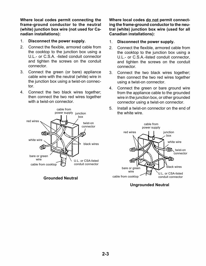
Where local codes do not permit connect-ing the frame-ground conductor to the neu-tral (white) junction box wire (used for allCanadian installations):
1. Disconnect the power supply.
2. Connect the flexible, armored cable fromthe cooktop to the junction box using aU.L.- or C.S.A.-listed conduit connector,and tighten the screws on the conduitconnector.
3. Connect the two black wires together;then connect the two red wires togetherusing a twist-on connector.
4. Connect the green or bare ground wirefrom the appliance cable to the groundedwire in the junction box, or other groundedconnector using a twist-on connector.
5. Install a twist-on connector on the end ofthe white wire.
1. Disconnect the power supply.
2. Connect the flexible, armored cable fromthe cooktop to the junction box using aU.L.- or C.S.A. -listed conduit connectorand tighten the screws on the conduitconnector.
3. Connect the green (or bare) appliancecable wire with the neutral (white) wire inthe junction box using a twist-on connec-tor.
4. Connect the two black wires together;then connect the two red wires togetherwith a twist-on connector.
Grounded Neutral
twist-onconnector
black wires
white wire
red wires
bare or greenwire
cable from cooktop
cable from cooktop
U.L. or CSA-listedconduit connector
Ungrounded Neutral
Where local codes permit connecting theframe-ground conductor to the neutral(white) junction box wire (not used for Ca-nadian installations):
2-4
6. Make the electrical connections as in-structed in the “Electrical Connections”beginning on page 2-2.
7. Turn on the power supply to the cooktop.
8. Depending on the model, push in and turneach control knob to the “Hl” position ortouch “ON” and turn each control knob tothe “Hl” position. Check the operation ofthe cooktop elements and indicator lights.
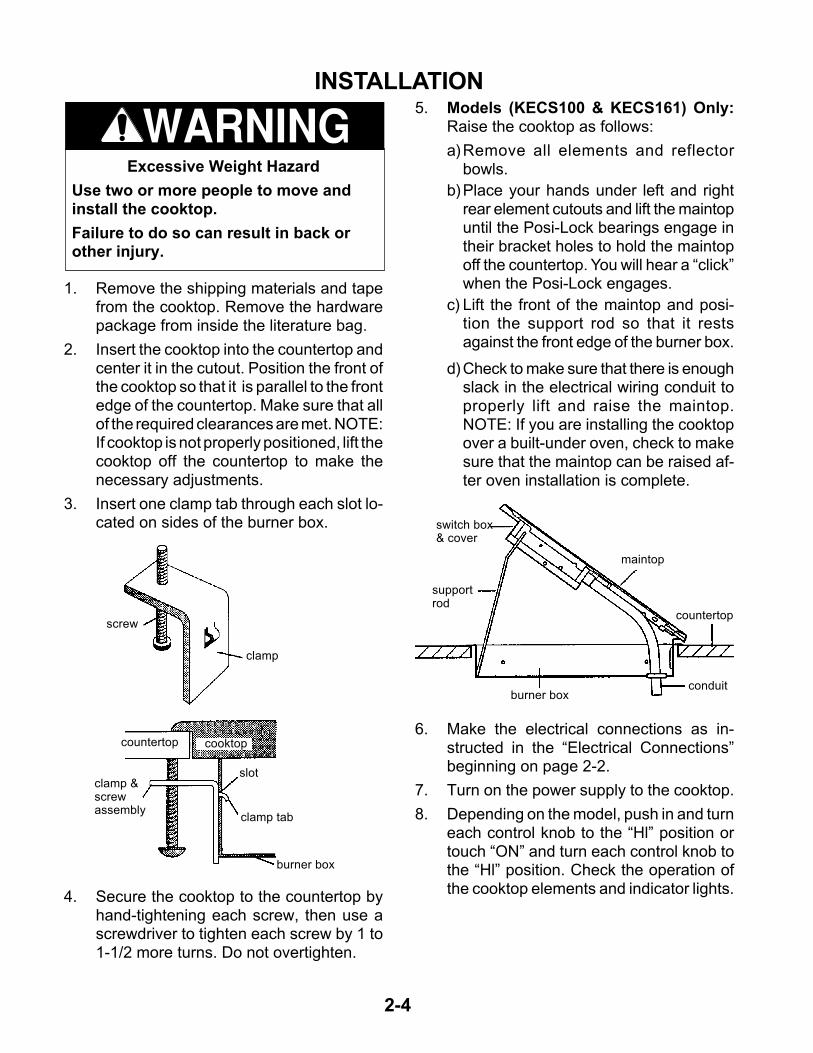
5. Models (KECS100 & KECS161) Only:Raise the cooktop as follows:
a)Remove all elements and reflectorbowls.
b)Place your hands under left and rightrear element cutouts and lift the maintopuntil the Posi-Lock bearings engage intheir bracket holes to hold the maintopoff the countertop. You will hear a “click”when the Posi-Lock engages.
c) Lift the front of the maintop and posi-tion the support rod so that it restsagainst the front edge of the burner box.
d)Check to make sure that there is enoughslack in the electrical wiring conduit toproperly lift and raise the maintop.NOTE: If you are installing the cooktopover a built-under oven, check to makesure that the maintop can be raised af-ter oven installation is complete.
INSTALLATION
1. Remove the shipping materials and tapefrom the cooktop. Remove the hardwarepackage from inside the literature bag.
2. Insert the cooktop into the countertop andcenter it in the cutout. Position the front ofthe cooktop so that it is parallel to the frontedge of the countertop. Make sure that allof the required clearances are met. NOTE:If cooktop is not properly positioned, lift thecooktop off the countertop to make thenecessary adjustments.
3. Insert one clamp tab through each slot lo-cated on sides of the burner box.
4. Secure the cooktop to the countertop byhand-tightening each screw, then use ascrewdriver to tighten each screw by 1 to1-1/2 more turns. Do not overtighten.
screw
clamp
countertop cooktop
slot
burner box
clamp &screwassembly
clamp tab
Excessive Weight Hazard
Use two or more people to move andinstall the cooktop.
Failure to do so can result in back orother injury.
WARNING
maintop
switch box& cover
supportrod
burner box
countertop
conduit
3-1
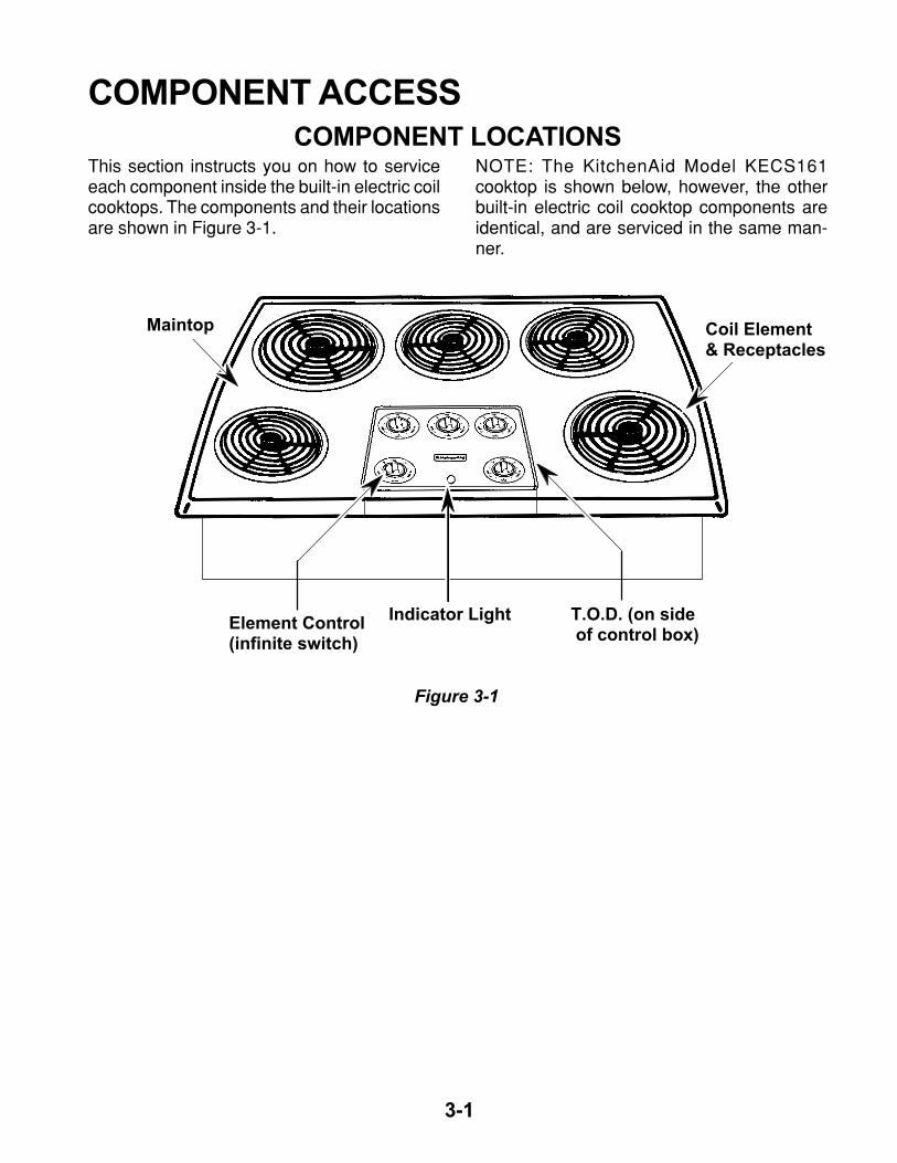
This section instructs you on how to serviceeach component inside the built-in electric coilcooktops. The components and their locationsare shown in Figure 3-1.
COMPONENT ACCESSCOMPONENT LOCATIONS
NOTE: The KitchenAid Model KECS161cooktop is shown below, however, the otherbuilt-in electric coil cooktop components areidentical, and are serviced in the same man-ner.
Coil Element & Receptacles
T.O.D. (on side of control box)
Indicator LightElement Control(infinite switch)
Maintop
Figure 3-1
3-2
WARNINGElectrical Shock Hazard
Disconnect from electrical supply before ser-vicing unit.
Failure to do so could result in death orelectrical shock.
CAUTION: When you work on the cooktop, becareful when handling the sheet metal parts.Sharp edges may be present, and you can cutyourself if you are not careful.
REMOVING THE MAINTOP (Coil Models)
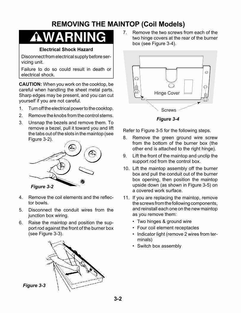
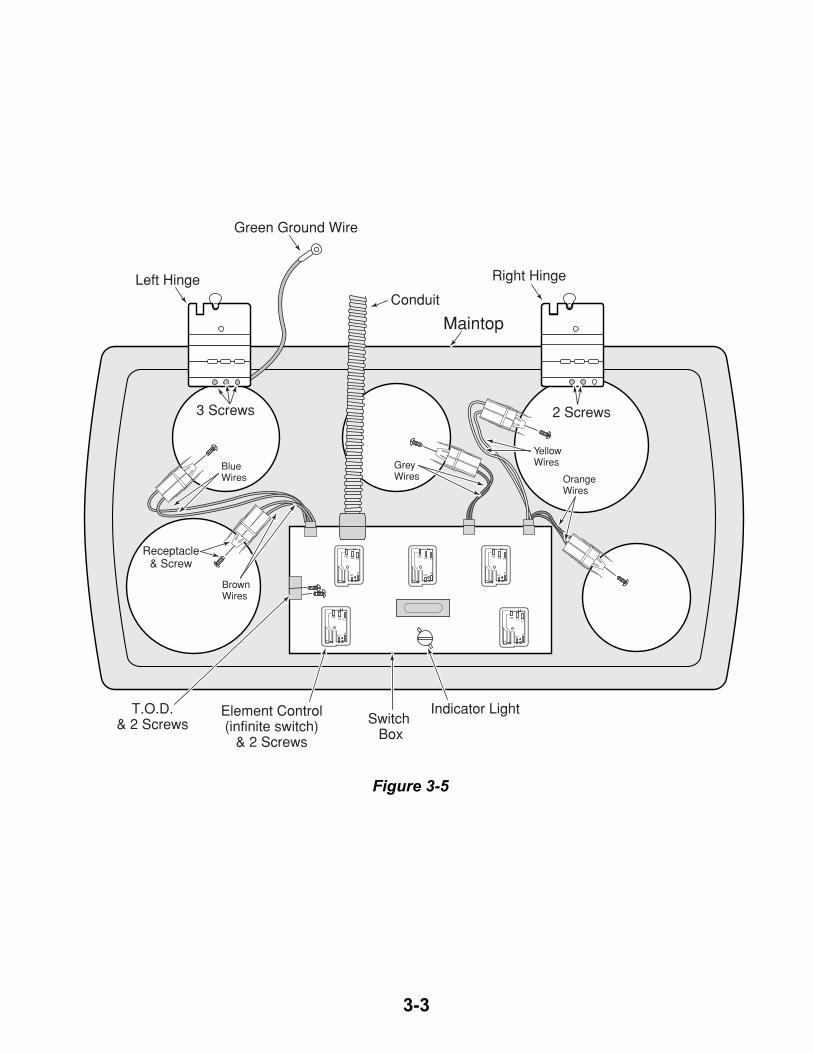
Refer to Figure 3-5 for the following steps.
8. Remove the green ground wire screwfrom the bottom of the burner box (theother end is attached to the right hinge).
9. Lift the front of the maintop and unclip thesupport rod from the control box.
10. Lift the maintop assembly off the burnerbox and pull the conduit out of the burnerbox opening, then position the maintopupside down (as shown in Figure 3-5) ona covered work surface.
11. If you are replacing the maintop, removethe screws from the following components,and reinstall each one on the new maintopas you remove them:
• Two hinges & ground wire
• Four coil element receptacles
• Indicator light (remove 2 wires from ter-minals)
• Switch box assembly
1. Turn off the electrical power to the cooktop.
2. Remove the knobs from the control stems.
3. Unsnap the bezels and remove them. Toremove a bezel, pull it toward you and liftthe tabs out of the slots in the maintop (seeFigure 3-2).
7. Remove the two screws from each of thetwo hinge covers at the rear of the burnerbox (see Figure 3-4).
4. Remove the coil elements and the reflec-tor bowls.
5. Disconnect the conduit wires from thejunction box wiring.
6. Raise the maintop and position the sup-port rod against the front of the burner box(see Figure 3-3).
Hinge Cover
Screws
Figure 3-2
Figure 3-3
Figure 3-4
3-3
L1L2
P
H2
H1
L1L2
P
H2
H1
L1L2
P
H2
H1
L1L2
P
H2
H1
L1L2
P
H2
H1
Green Ground Wire
Left HingeConduit
Right Hinge
3 Screws 2 Screws
Receptacle& Screw
Switch Box
Indicator LightElement Control(infinite switch)
& 2 Screws
T.O.D.& 2 Screws
Blue Wires
Brown Wires
Grey Wires
Yellow Wires
Orange Wires
Maintop
Figure 3-5
3-4
WARNINGElectrical Shock Hazard
Disconnect from electrical supply before ser-vicing unit.
Failure to do so could result in death orelectrical shock.
CAUTION: When you work on the cooktop, becareful when handling the sheet metal parts.Sharp edges may be present, and you can cutyourself if you are not careful.
REMOVING THE INDICATOR LIGHT, AN ELEMENTCONTROL, A COIL RECEPTACLE, & THE T.O.D.
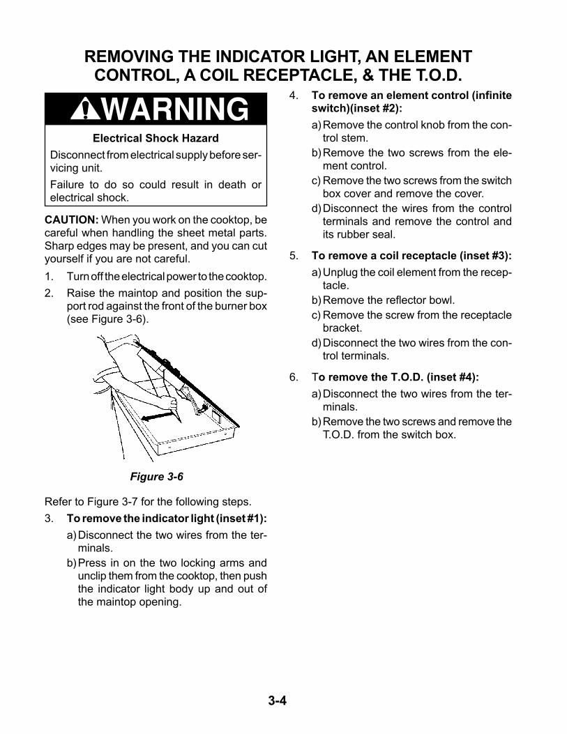
1. Turn off the electrical power to the cooktop.
2. Raise the maintop and position the sup-port rod against the front of the burner box(see Figure 3-6).
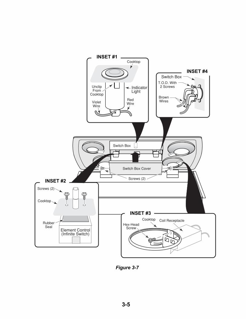
Refer to Figure 3-7 for the following steps.
3. To remove the indicator light (inset #1):
a)Disconnect the two wires from the ter-minals.
b)Press in on the two locking arms andunclip them from the cooktop, then pushthe indicator light body up and out ofthe maintop opening.
4. To remove an element control (infiniteswitch)(inset #2):
a)Remove the control knob from the con-trol stem.
b)Remove the two screws from the ele-ment control.
c) Remove the two screws from the switchbox cover and remove the cover.
d)Disconnect the wires from the controlterminals and remove the control andits rubber seal.
5. To remove a coil receptacle (inset #3):
a)Unplug the coil element from the recep-tacle.
b)Remove the reflector bowl.
c) Remove the screw from the receptaclebracket.
d)Disconnect the two wires from the con-trol terminals.
6. To remove the T.O.D. (inset #4):
a)Disconnect the two wires from the ter-minals.
b)Remove the two screws and remove theT.O.D. from the switch box.
Figure 3-6
3-5
T.O.D. With2 Screws
BrownWiresViolet
Wire
RedWire
UnclipFrom
Cooktop
IndicatorLight
Cooktop
Screws (2)
Screws (2)
Hex-HeadScrew
RubberSeal
Element Control(Infinite Switch)
Switch Box
Cooktop
Coil ReceptacleCooktop
Switch Box Cover
Switch Box
Figure 3-7
INSET #1
INSET #4
INSET #3
INSET #2
3-6
Maintop Screw(1 of 14)
CeramicMaintop
ControlKnob
WARNINGElectrical Shock Hazard
Disconnect from electrical supply before ser-vicing unit.
Failure to do so could result in death orelectrical shock.
CAUTION: When you work on the cooktop, becareful when handling the sheet metal parts.Sharp edges may be present, and you can cutyourself if you are not careful.
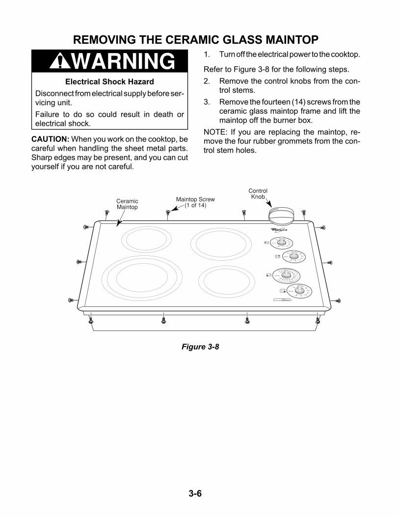
REMOVING THE CERAMIC GLASS MAINTOP1. Turn off the electrical power to the cooktop.
Refer to Figure 3-8 for the following steps.
2. Remove the control knobs from the con-trol stems.
3. Remove the fourteen (14) screws from theceramic glass maintop frame and lift themaintop off the burner box.
NOTE: If you are replacing the maintop, re-move the four rubber grommets from the con-trol stem holes.
Figure 3-8
4-1
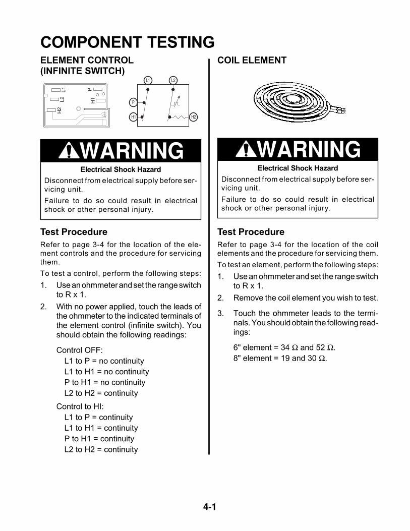
COMPONENT TESTINGELEMENT CONTROL(INFINITE SWITCH)
Electrical Shock Hazard
Disconnect from electrical supply before ser-
vicing unit.
Failure to do so could result in electrical
shock or other personal injury.
WARNING
L1L2
P
H2
H1
L1
P
H1 H2
L2
Test Procedure
Refer to page 3-4 for the location of the ele-
ment controls and the procedure for servicing
them.
To test a control, perform the following steps:
1. Use an ohmmeter and set the range switchto R x 1.
2. With no power applied, touch the leads ofthe ohmmeter to the indicated terminals ofthe element control (infinite switch). Youshould obtain the following readings:
Control OFF:
L1 to P = no continuity
L1 to H1 = no continuity
P to H1 = no continuity
L2 to H2 = continuity
Control to HI:
L1 to P = continuity
L1 to H1 = continuity
P to H1 = continuity
L2 to H2 = continuity
COIL ELEMENT
Electrical Shock Hazard
Disconnect from electrical supply before ser-
vicing unit.
Failure to do so could result in electrical
shock or other personal injury.
WARNING
Test Procedure
Refer to page 3-4 for the location of the coil
elements and the procedure for servicing them.
To test an element, perform the following steps:
1. Use an ohmmeter and set the range switchto R x 1.
2. Remove the coil element you wish to test.
3. Touch the ohmmeter leads to the termi-nals. You should obtain the following read-ings:
6" element = 34 Ω and 52 Ω.
8" element = 19 and 30 Ω.
4-2
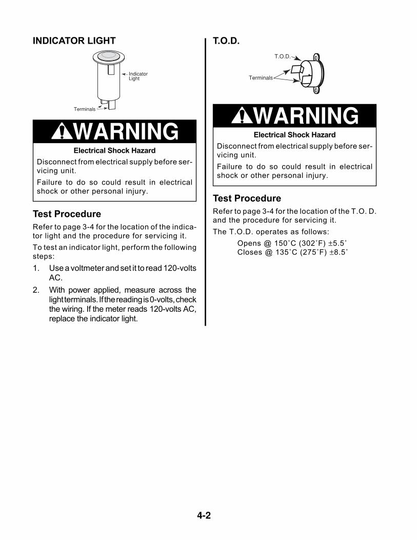
INDICATOR LIGHT
Electrical Shock Hazard
Disconnect from electrical supply before ser-
vicing unit.
Failure to do so could result in electrical
shock or other personal injury.
WARNING
Test Procedure
Refer to page 3-4 for the location of the indica-
tor light and the procedure for servicing it.
To test an indicator light, perform the following
steps:
1. Use a voltmeter and set it to read 120-voltsAC.
2. With power applied, measure across thelight terminals. If the reading is 0-volts, checkthe wiring. If the meter reads 120-volts AC,replace the indicator light.
IndicatorLight
Terminals
T.O.D.
Terminals
T.O.D.
Electrical Shock Hazard
Disconnect from electrical supply before ser-
vicing unit.
Failure to do so could result in electrical
shock or other personal injury.
WARNING
Test Procedure
Refer to page 3-4 for the location of the T.O. D.
and the procedure for servicing it.
The T.O.D. operates as follows:
Opens @ 150˚C (302˚F) ±5.5˚
Closes @ 135˚C (275˚F) ±8.5˚
4-3
2A 2B
1A 1B
2A 2B
1B1A
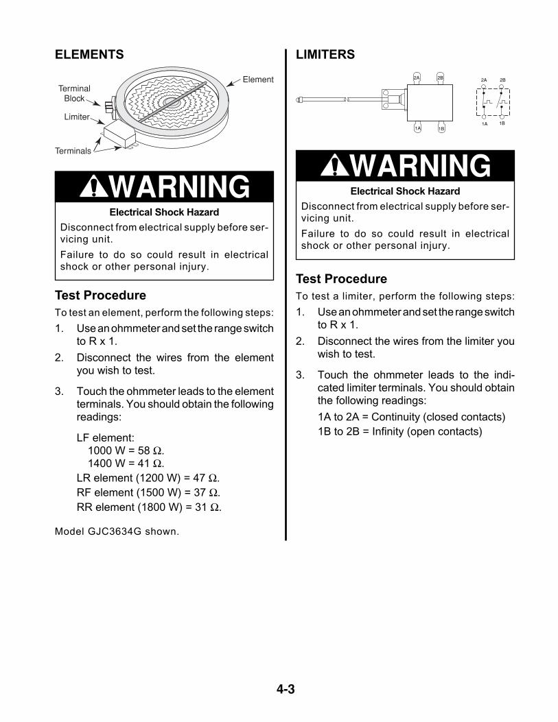
LIMITERS
Electrical Shock Hazard
Disconnect from electrical supply before ser-
vicing unit.
Failure to do so could result in electrical
shock or other personal injury.
WARNING
Test Procedure
To test a limiter, perform the following steps:
1. Use an ohmmeter and set the range switchto R x 1.
2. Disconnect the wires from the limiter youwish to test.
3. Touch the ohmmeter leads to the indi-cated limiter terminals. You should obtainthe following readings:
1A to 2A = Continuity (closed contacts)
1B to 2B = Infinity (open contacts)
ELEMENTS
Electrical Shock Hazard
Disconnect from electrical supply before ser-
vicing unit.
Failure to do so could result in electrical
shock or other personal injury.
WARNING
Test Procedure
To test an element, perform the following steps:
1. Use an ohmmeter and set the range switchto R x 1.
2. Disconnect the wires from the elementyou wish to test.
3. Touch the ohmmeter leads to the elementterminals. You should obtain the followingreadings:
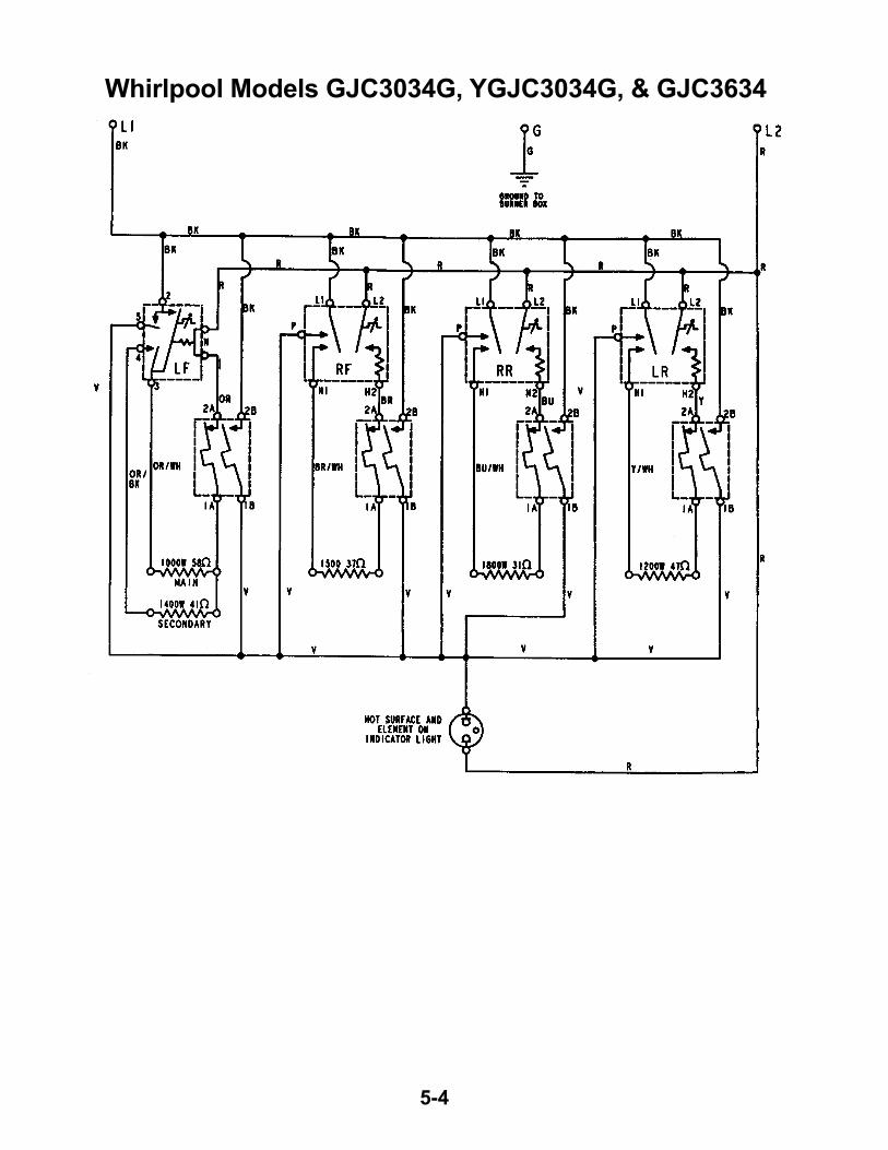
LF element:1000 W = 58 Ω.1400 W = 41 Ω.
LR element (1200 W) = 47 Ω.
RF element (1500 W) = 37 Ω.
RR element (1800 W) = 31 Ω.
Element
Limiter
TerminalBlock
Terminals
Model GJC3634G shown.

4-4
— NOTES —
5-1
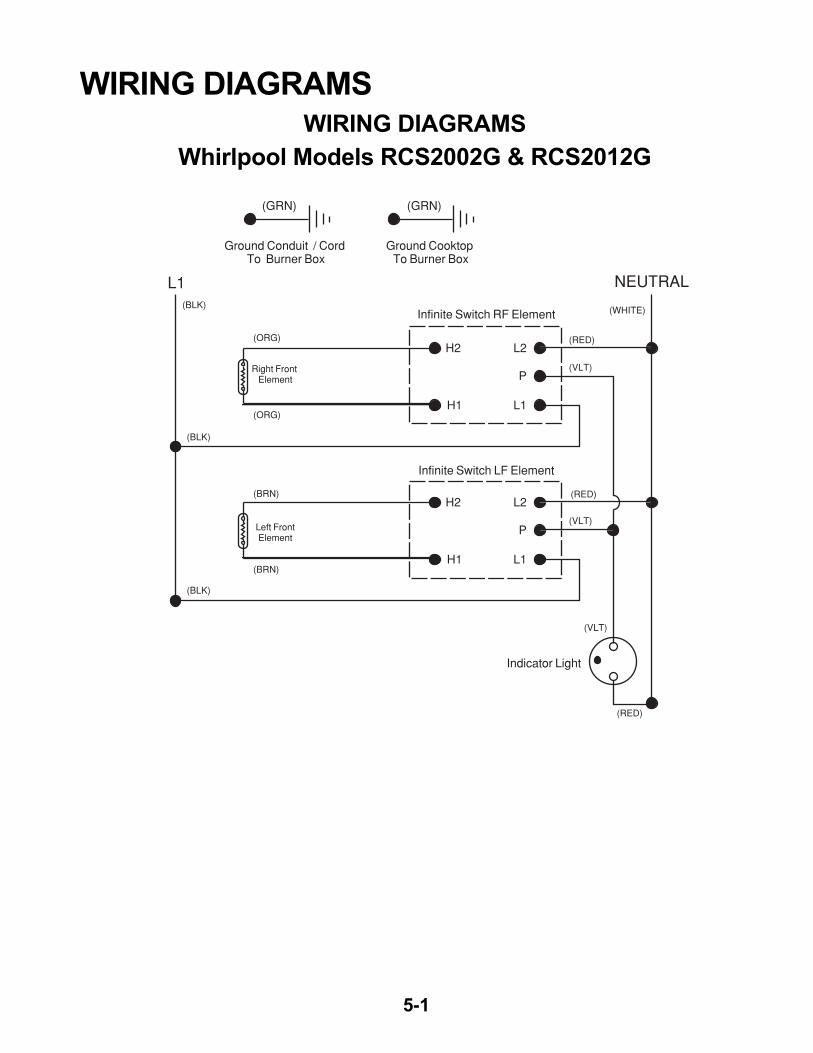
WIRING DIAGRAMSWIRING DIAGRAMS
Whirlpool Models RCS2002G & RCS2012G
L1 NEUTRAL
(ORG)
(ORG)
(RED)
(RED)
(RED)
(WHITE)(BLK)
(BLK)
(BLK)
(BRN)
(BRN)
(VLT)
(VLT)
(VLT)
H2 L2
P
L1H1
H2 L2
P
L1H1
(GRN) (GRN)
Ground Conduit / Cord To Burner Box
Ground Cooktop To Burner Box
Left FrontElement
Right Front Element
Infinite Switch RF Element
Infinite Switch LF Element
Indicator Light
5-2
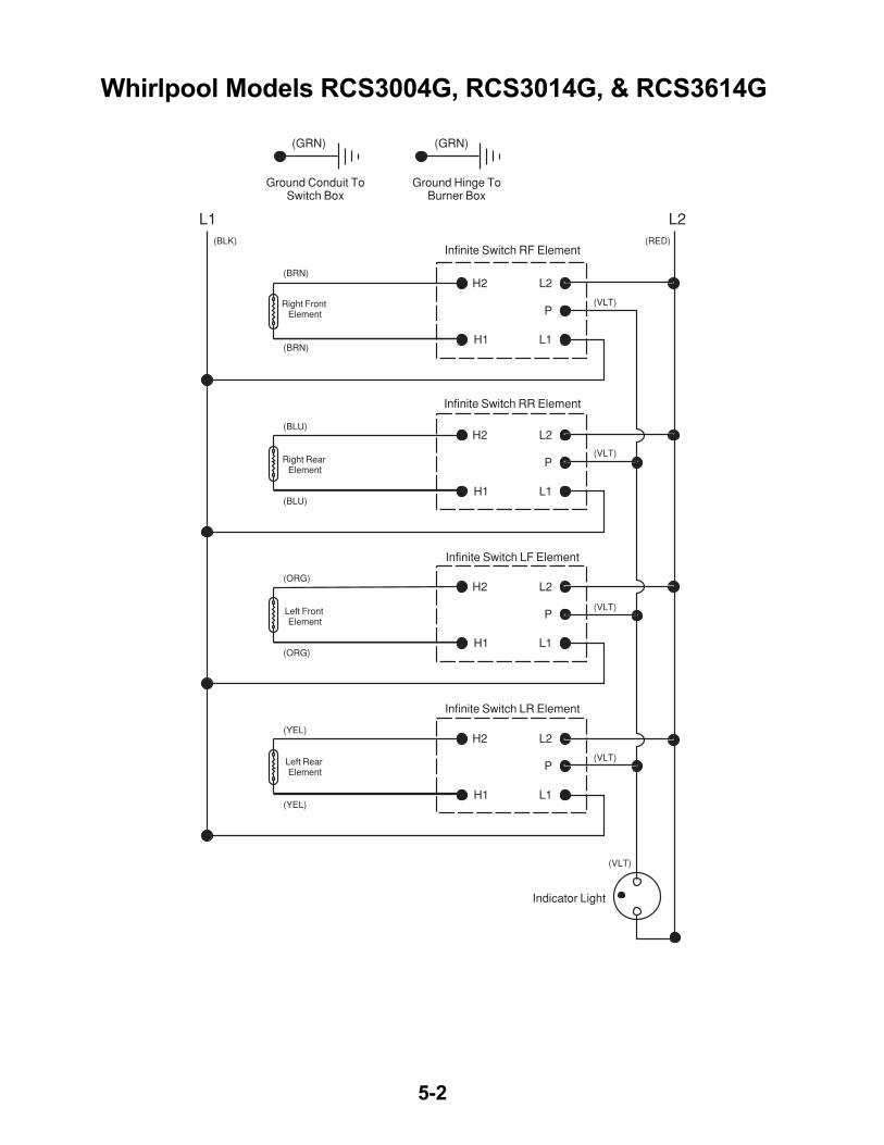
Whirlpool Models RCS3004G, RCS3014G, & RCS3614G
L1 L2
(BRN)
(RED)(BLK)
(BLU)
(ORG)
(YEL)
(BRN)
(VLT)
(VLT)
(VLT)
(VLT)
(VLT)
(BLU)
(ORG)
(YEL)
H2 L2
P
L1H1
H2 L2
P
L1H1
H2 L2
P
L1H1
H2 L2
P
L1H1
(GRN) (GRN)
Ground Conduit ToSwitch Box
Ground Hinge ToBurner Box
Left Rear Element
Left Front Element
Right Rear Element
Right Front Element
Infinite Switch RF Element
Infinite Switch RR Element
Infinite Switch LF Element
Infinite Switch LR Element
Indicator Light
5-3
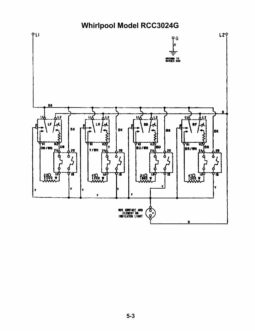
Whirlpool Model RCC3024G
5-4
Whirlpool Models GJC3034G, YGJC3034G, & GJC3634
5-5
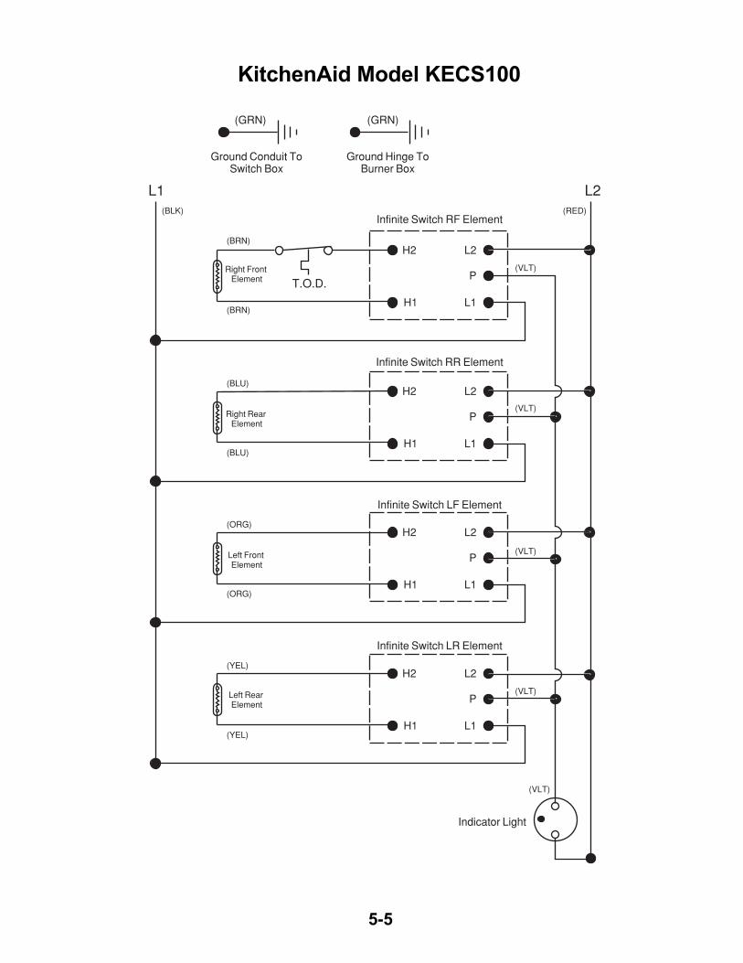
KitchenAid Model KECS100
L1 L2
(BRN)
(RED)(BLK)
(BLU)
(ORG)
(YEL)
(BRN)
(VLT)
(VLT)
(VLT)
(VLT)
(VLT)
(BLU)
(ORG)
(YEL)
H2 L2
P
L1H1
H2 L2
P
L1H1
H2 L2
P
L1H1
H2 L2
P
L1H1
(GRN) (GRN)
Ground Conduit ToSwitch Box
Ground Hinge ToBurner Box
Left Rear Element
Left Front Element
Right Rear Element
Right Front Element
Infinite Switch RF Element
Infinite Switch RR Element
Infinite Switch LF Element
Infinite Switch LR Element
Indicator Light
T.O.D.
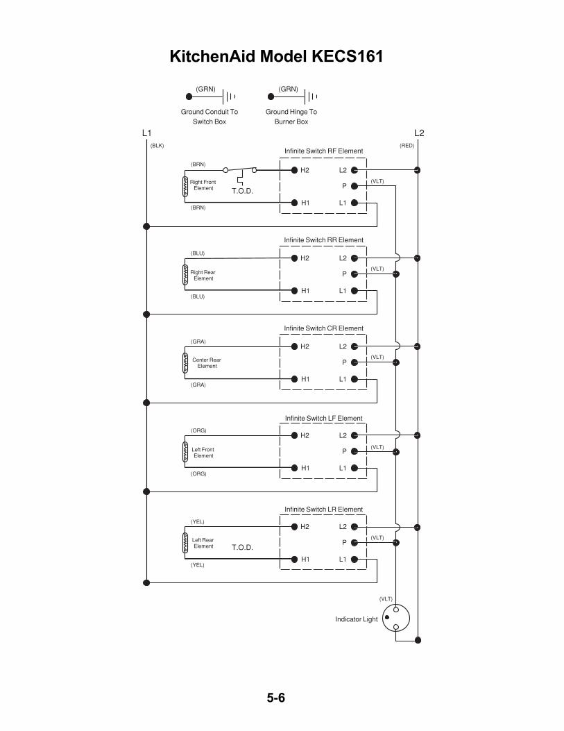
5-6
L1 L2
T.O.D.
(BRN)
(RED)(BLK)
(BLU)
(ORG)
(YEL)
(BRN)
(VLT)
(VLT)
(VLT)
(VLT)
(VLT)
(BLU)
(ORG)
(YEL)
H2 L2
P
L1H1
H2 L2
P
L1H1
H2 L2
P
L1H1
T.O.D.
H2 L2
P
L1H1
(GRN) (GRN)
Ground Conduit ToSwitch Box
Ground Hinge ToBurner Box
Left Rear Element
Left Front Element
Right Rear Element
Right Front Element
Infinite Switch RF Element
Infinite Switch RR Element
(GRA)
(GRA)
(VLT)
H2 L2
P
L1H1
Center Rear Element
Infinite Switch CR Element
Infinite Switch LF Element
Infinite Switch LR Element
Indicator Light
KitchenAid Model KECS161
5-7
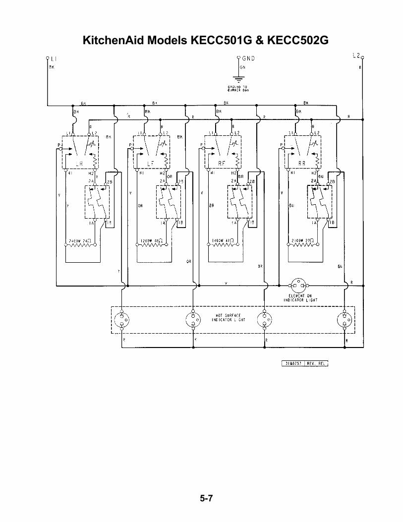
KitchenAid Models KECC501G & KECC502G
5-8
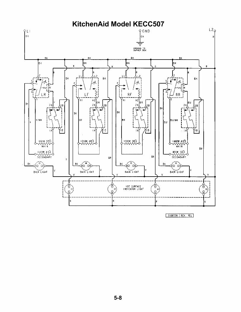
KitchenAid Model KECC507
5-9
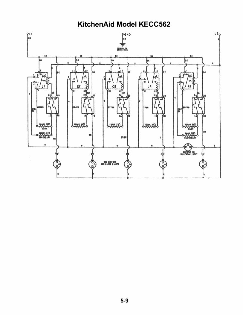
KitchenAid Model KECC562
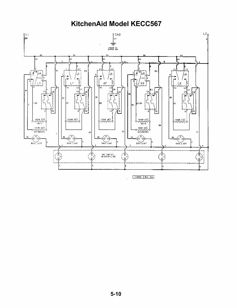
5-10
KitchenAid Model KECC567
6-1
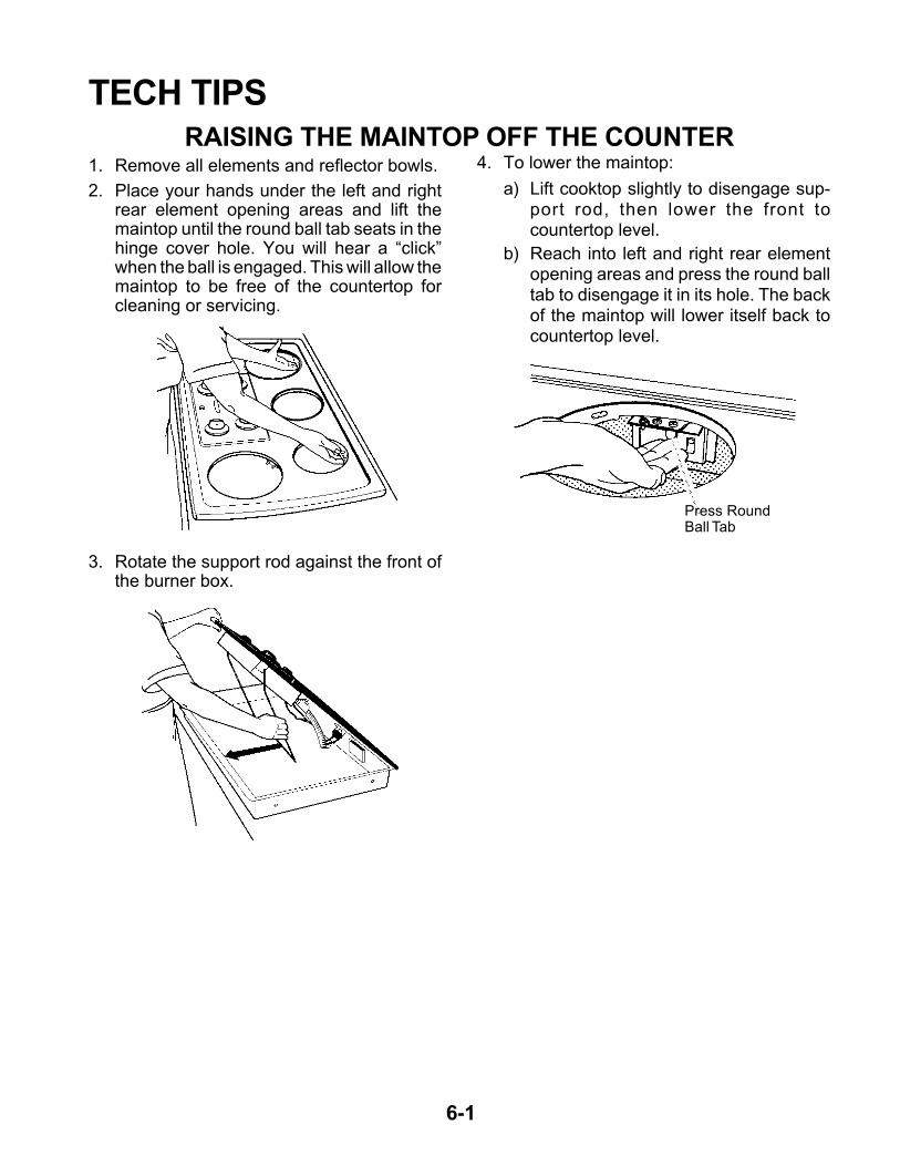
TECH TIPSRAISING THE MAINTOP OFF THE COUNTER
1. Remove all elements and reflector bowls.
2. Place your hands under the left and rightrear element opening areas and lift themaintop until the round ball tab seats in thehinge cover hole. You will hear a “click”when the ball is engaged. This will allow themaintop to be free of the countertop forcleaning or servicing.
3. Rotate the support rod against the front ofthe burner box.
4. To lower the maintop:
a) Lift cooktop slightly to disengage sup-port rod, then lower the front tocountertop level.
b) Reach into left and right rear elementopening areas and press the round balltab to disengage it in its hole. The backof the maintop will lower itself back tocountertop level.
Press RoundBall Tab

6-2
REQUESTING ASSISTANCE OR SERVICEIf you need assistance or service in theU.S. A.:
Call the KitchenAid Consumer Assistance Cen-ter toll free, at
1-800-422-1230, OR
Call the Whirlpool Consumer AssistanceCenter,toll free at:
1-800-253-1301.
If you need assistance or service in Canada:
Call the Inglis Limited Consumer AssistanceCenter telephone number toll-free, 8:30 a.m.to 6:00 p.m. (EST) at:
1-800-461-5681.
Our consultants are available to assist you.
When calling, please have the purchase date,and the complete model and serial number ofyour appliance handy. This information will helpwith your request.
Our consultants provide assistance with:
• Features and specifications on our fullline of appliances.
• Installation information.
• Use and maintenance procedures.
• Accessory and repair parts sales.
• Specialized customer assistance(Spanish & French (Canada) speaking,hearing impaired, limited vision, etc.).
• Referrals to local dealers, service com-panies, and repair parts distributors.
KitchenAid and Whirlpool service techniciansare trained to fulfill the product warranty andprovide after-warranty service, anywhere in theUnited States. To locate the authorizedKitchenAid or Whirlpool service company inyour area, you can also look in your telephonedirectory Yellow Pages.
If you need to order replacement parts, werecommend that you only use factory autho-rized parts. These parts will fit right and workright, because they are made with the sameprecision used to build every new KitchenAidand Whirlpool appliance.
To locate factory authorized replacement partsin your area, call our Consumer AssistanceCenter telephone number or your nearest au-thorized service center.
If you need further assistance, you can writeto KitchenAid, or Whirlpool, with any questionsor concerns at:
KitchenAid/Whirlpool Brand Home Appliances
Consumer Assistance Centerc/o Correspondence Dept.2000 North M-63Benton Harbor, Ml 49022-2692
In Canada, contact:
Consumer Relations DepartmentInglis Limited1901 Minnesota CourtMississauga, Ontario L5N 3A7
Please include a daytime phone number inyour correspondence.
6-3
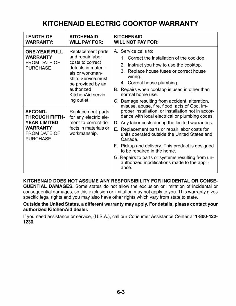
KITCHENAID ELECTRIC COOKTOP WARRANTY
SECOND-THROUGH FIFTH-YEAR LIMITEDWARRANTYFROM DATE OFPURCHASE.
ONE-YEAR FULLWARRANTYFROM DATE OFPURCHASE.
LENGTH OFWARRANTY:
KITCHENAIDWILL PAY FOR:
Replacement partsand repair laborcosts to correctdefects in materi-als or workman-ship. Service mustbe provided by anauthorizedKitchenAid servic-ing outlet.
Replacement partsfor any electric ele-ment to correct de-fects in materials orworkmanship.
KITCHENAIDWILL NOT PAY FOR:
A. Service calls to:
1. Correct the installation of the cooktop.
2. Instruct you how to use the cooktop.
3. Replace house fuses or correct housewiring.
4. Correct house plumbing.
B. Repairs when cooktop is used in other thannormal home use.
C. Damage resulting from accident, alteration,misuse, abuse, fire, flood, acts of God, im-proper installation, or installation not in accor-dance with local electrical or plumbing codes.
D. Any labor costs during the limited warranties.
E. Replacement parts or repair labor costs forunits operated outside the United States andCanada.
F. Pickup and delivery. This product is designedto be repaired in the home.
G. Repairs to parts or systems resulting from un-authorized modifications made to the appli-ance.
KITCHENAID DOES NOT ASSUME ANY RESPONSIBILITY FOR INCIDENTAL OR CONSE-QUENTIAL DAMAGES. Some states do not allow the exclusion or limitation of incidental orconsequential damages, so this exclusion or limitation may not apply to you. This warranty givesspecific legal rights and you may also have other rights which vary from state to state.
Outside the United States, a different warranty may apply. For details, please contact yourauthorized KitchenAid dealer.
If you need assistance or service, (U.S.A.), call our Consumer Assistance Center at 1-800-422-1230.
6-4
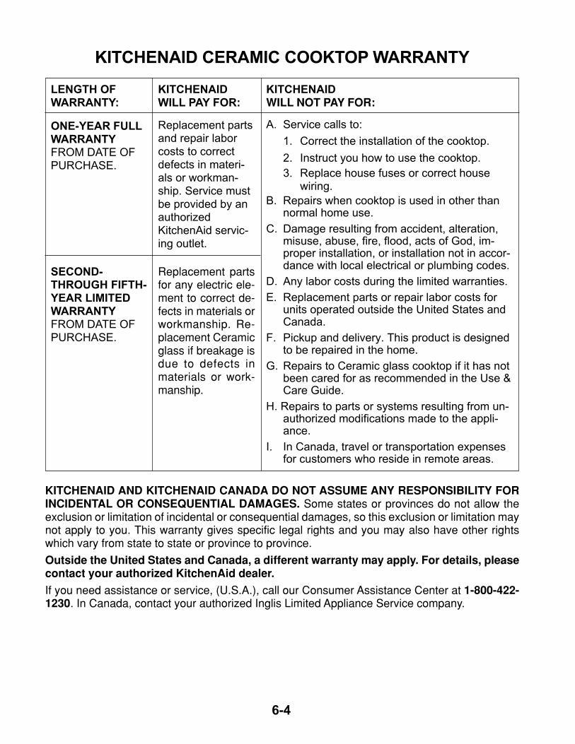
KITCHENAID CERAMIC COOKTOP WARRANTY
SECOND-THROUGH FIFTH-YEAR LIMITEDWARRANTYFROM DATE OFPURCHASE.
ONE-YEAR FULLWARRANTYFROM DATE OFPURCHASE.
LENGTH OFWARRANTY:
KITCHENAIDWILL PAY FOR:
Replacement partsand repair laborcosts to correctdefects in materi-als or workman-ship. Service mustbe provided by anauthorizedKitchenAid servic-ing outlet.
Replacement partsfor any electric ele-ment to correct de-fects in materials orworkmanship. Re-placement Ceramicglass if breakage isdue to defects inmaterials or work-manship.
KITCHENAIDWILL NOT PAY FOR:
A. Service calls to:
1. Correct the installation of the cooktop.
2. Instruct you how to use the cooktop.
3. Replace house fuses or correct housewiring.
B. Repairs when cooktop is used in other thannormal home use.
C. Damage resulting from accident, alteration,misuse, abuse, fire, flood, acts of God, im-proper installation, or installation not in accor-dance with local electrical or plumbing codes.
D. Any labor costs during the limited warranties.
E. Replacement parts or repair labor costs forunits operated outside the United States andCanada.
F. Pickup and delivery. This product is designedto be repaired in the home.
G. Repairs to Ceramic glass cooktop if it has notbeen cared for as recommended in the Use &Care Guide.
H. Repairs to parts or systems resulting from un-authorized modifications made to the appli-ance.
I. In Canada, travel or transportation expensesfor customers who reside in remote areas.
KITCHENAID AND KITCHENAID CANADA DO NOT ASSUME ANY RESPONSIBILITY FORINCIDENTAL OR CONSEQUENTIAL DAMAGES. Some states or provinces do not allow theexclusion or limitation of incidental or consequential damages, so this exclusion or limitation maynot apply to you. This warranty gives specific legal rights and you may also have other rightswhich vary from state to state or province to province.
Outside the United States and Canada, a different warranty may apply. For details, pleasecontact your authorized KitchenAid dealer.
If you need assistance or service, (U.S.A.), call our Consumer Assistance Center at 1-800-422-1230. In Canada, contact your authorized Inglis Limited Appliance Service company.
6-5
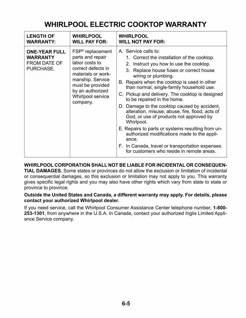
WHIRLPOOL ELECTRIC COOKTOP WARRANTY
ONE-YEAR FULLWARRANTYFROM DATE OFPURCHASE.
LENGTH OFWARRANTY:
WHIRLPOOLWILL PAY FOR:
FSP® replacementparts and repairlabor costs tocorrect defects inmaterials or work-manship. Servicemust be providedby an authorizedWhirlpool servicecompany.
WHIRLPOOLWILL NOT PAY FOR:
A. Service calls to:
1. Correct the installation of the cooktop.
2. Instruct you how to use the cooktop.
3. Replace house fuses or correct housewiring or plumbing.
B. Repairs when the cooktop is used in otherthan normal, single-family household use.
C. Pickup and delivery. The cooktop is designedto be repaired in the home.
D. Damage to the cooktop caused by accident,alteration, misuse, abuse, fire, flood, acts ofGod, or use of products not approved byWhirlpool.
E. Repairs to parts or systems resulting from un-authorized modifications made to the appli-ance.
F. In Canada, travel or transportation expensesfor customers who reside in remote areas.
WHIRLPOOL CORPORATION SHALL NOT BE LIABLE FOR INCIDENTAL OR CONSEQUEN-TIAL DAMAGES. Some states or provinces do not allow the exclusion or limitation of incidentalor consequential damages, so this exclusion or limitation may not apply to you. This warrantygives specific legal rights and you may also have other rights which vary from state to state orprovince to province.
Outside the United States and Canada, a different warranty may apply. For details, pleasecontact your authorized Whirlpool dealer.
If you need service, call the Whirlpool Consumer Assistance Center telephone number, 1-800-253-1301, from anywhere in the U.S.A. In Canada, contact your authorized Inglis Limited Appli-ance Service company.
6-6
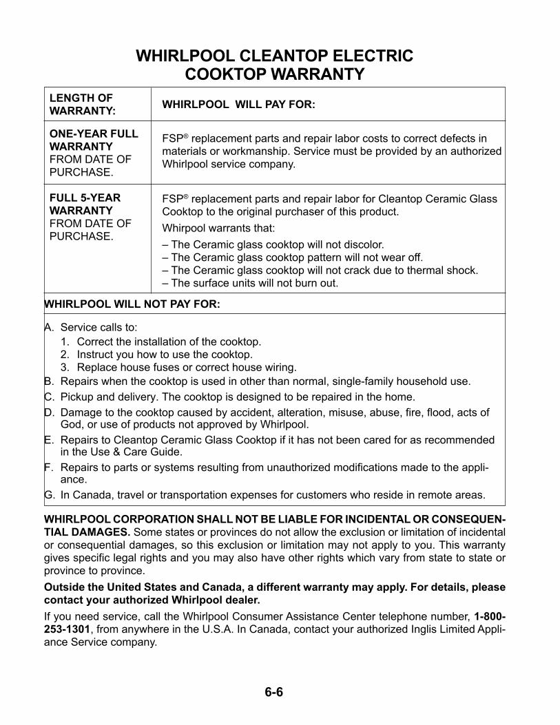
WHIRLPOOL CLEANTOP ELECTRICCOOKTOP WARRANTY
ONE-YEAR FULLWARRANTYFROM DATE OFPURCHASE.
LENGTH OFWARRANTY:
WHIRLPOOL CORPORATION SHALL NOT BE LIABLE FOR INCIDENTAL OR CONSEQUEN-TIAL DAMAGES. Some states or provinces do not allow the exclusion or limitation of incidentalor consequential damages, so this exclusion or limitation may not apply to you. This warrantygives specific legal rights and you may also have other rights which vary from state to state orprovince to province.
Outside the United States and Canada, a different warranty may apply. For details, pleasecontact your authorized Whirlpool dealer.
If you need service, call the Whirlpool Consumer Assistance Center telephone number, 1-800-253-1301, from anywhere in the U.S.A. In Canada, contact your authorized Inglis Limited Appli-ance Service company.
FULL 5-YEARWARRANTYFROM DATE OFPURCHASE.
WHIRLPOOL WILL PAY FOR:
FSP® replacement parts and repair labor costs to correct defects inmaterials or workmanship. Service must be provided by an authorizedWhirlpool service company.
FSP® replacement parts and repair labor for Cleantop Ceramic GlassCooktop to the original purchaser of this product.
Whirpool warrants that:
– The Ceramic glass cooktop will not discolor.– The Ceramic glass cooktop pattern will not wear off.– The Ceramic glass cooktop will not crack due to thermal shock.– The surface units will not burn out.
WHIRLPOOL WILL NOT PAY FOR:
A. Service calls to:
1. Correct the installation of the cooktop.2. Instruct you how to use the cooktop.3. Replace house fuses or correct house wiring.
B. Repairs when the cooktop is used in other than normal, single-family household use.
C. Pickup and delivery. The cooktop is designed to be repaired in the home.
D. Damage to the cooktop caused by accident, alteration, misuse, abuse, fire, flood, acts ofGod, or use of products not approved by Whirlpool.
E. Repairs to Cleantop Ceramic Glass Cooktop if it has not been cared for as recommendedin the Use & Care Guide.
F. Repairs to parts or systems resulting from unauthorized modifications made to the appli-ance.
G. In Canada, travel or transportation expenses for customers who reside in remote areas.


![ME-30 - SYNFO - The Synthesizer Databasesynfo.nl/servicemanuals/Boss/ME-30_SERVICE_NOTES.pdf · ME-30 Aug, 1997 4 EXPLODED VIEW PARTS LIST/分解図パーツリスト [PARTS] No](https://img.pdfslide.tips/doc/110x75/5b830ee07f8b9a940b8c3ff4/me-30-synfo-the-synthesizer-me-30-aug-1997-4-exploded-view-parts-list.jpg)