Embed Size (px)
Citation preview

Wideband operation of Mach-Zehnder interferomertic magneto-optical isolator using
phase adjustment Yuya Shoji and Tetsuya Mizumoto
Department of Electrical and Electronic Engineering, Tokyo Institute of Technology, 2-12-1-S3-11 Ookayama, Meguro-ku, Tokyo 152-8550, Japan
Abstract: A wideband operation of a magneto-optical isolator is demonstrated. The isolator is based on a Mach-Zehnder interferometer employing nonreciprocal phase shift. The wideband operation is achieved by adjusting a reciprocal phase difference in the interferometer. We designed and fabricated a wideband isolator with a magneto-optic garnet waveguide. The isolation ratio of 15-25dB was obtained in a wavelength range from 1530nm to 1640nm.
©2007 Optical Society of America
OCIS codes: (230.3120) Integrated optics devices; (230.3240) Isolators.
References and links
1. K. Ando, T. Okoshi, and N. Koshizuka, “Waveguide magneto-optical isolator fabricated by laser annealing,” Appl. Phys. Lett. 53, 4-6 (1988).
2. T. Shintaku, “Integrated optical isolator based on efficient nonreciprocal radiation mode conversion,” Appl. Phys. Lett. 73, 1946-1948 (1998).
3. F. Auracher and H. H. Witte, “A new design for an integrated optical isolator,” Opt. Commun. 13, 435-438 (1975).
4. T. Mizumoto, K. Oochi, T. Harada, and Y. Naito, “Measurement of optical nonreciprocal phase shift in a Bi-substituted Gd3Fe5O12 film and application to waveguide-type optical circulator,” J. Lightwave Technol. LT-4, 347-352 (1986).
5. J. Fujita, M. Levy, R. M. Osgood, Jr. L. Wilkens, and H. Dötsch, “Waveguide optical isolator based on Mach-Zehnder interferometer,” Appl. Phys. Lett. 76, 2158-2160 (2000).
6. H. Dötsch, N. Bahlmann, O. Zhuromskyy, M. Hammer, L. Wilkens, R. Gerhardt, and P. Hertel, “Application of magneto-optical waveguides in integrated optics: review,” J. Opt. Soc. Am. B 22, 240-253 (2005).
7. H. Yokoi, T. Mizumoto, N. Shinjo, N. Futakuchi, and Y. Nakano, “Demonstration of an optical isolator, with a semiconductor guiding layer that was obtained by use of a nonreciprocal phase shift,” Appl. Opt. 39, 6158-6164 (2000).
8. Y. Shoji and T. Mizumoto, “Wideband design of nonreciprocal phase shift magneto-optical isolators using phase adjustment in Mach-Zehnder interferometer,” Appl. Opt. 45, 7144-7150 (2006).
9. Y. Shoji and T. Mizumoto, “Ultra-wideband design of waveguide magneto-optical isolator operating in 1.31μm and 1.55μm band,” Opt. Express 15, 639-645 (2007).
1. Introduction
Optical nonreciprocal devices, such as isolators and circulators, are important components in high speed optical communication systems. At present, only bulk isolators are commercially available, which are not suitable for integration. In addition, the operation bandwidth is narrow due to a large wavelength dependence of Faraday rotation of magneto-optical materials. Ando et al. demonstrated a waveguide isolator using TE-TM mode conversion with the isolation ratio of 12.5dB [1]. Shintaku demonstrated a waveguide isolator using nonreciprocal radiation mode conversion with the isolation ratio of 27dB [2]. However they suffered small fabrication tolerance. Also, the operation bandwidth is narrow. A waveguide isolator with high isolation ratio in a wider wavelength range is desired.
A waveguide isolator employing nonreciprocal phase shift has been intensively investigated in Mach-Zehnder interferometer (MZI) configuration with nonreciprocal and
#86506 - $15.00 USD Received 15 Aug 2007; revised 26 Sep 2007; accepted 26 Sep 2007; published 28 Sep 2007
(C) 2007 OSA 1 October 2007 / Vol. 15, No. 20 / OPTICS EXPRESS 13446

reciprocal phase shifters [3-7]. It is less sensitive to a fabrication error because there is no need of phase matching between orthogonally polarized modes. Recently, we proposed a wideband design of the isolator using phase adjustment in MZI [8,9]. In this paper, we fabricated a wideband isolator with a magneto-optic garnet and demonstrated the wideband operation experimentally.
2. Wideband design
The MZI is composed of nonreciprocal phase shifter (NPS) and reciprocal phase sifter (RPS) as shown in Fig. 1. External magnetic fields are applied to the arms of NPS in anti-parallel directions to obtain a nonreciprocal phase difference (θN) in a push-pull manner. Reciprocal phase difference (θR) is provided by an optical path difference between two arms. In the conventional design, θR is set to be +π/2 to cancel the θN in forward direction, which results in constructive interference, or add to θN in backward direction, which results in destructive interference. Since the θN and θR decrease monotonically as the wavelength becomes longer, deviations of nonreciprocal and reciprocal phase difference from respective designed values are cancelled in the forward direction, while added in the backward direction as shown in Fig. 2(a) and 2(b). This behavior determines the wavelength dependence of the isolator operation and large backward loss is obtained only in a narrow wavelength range.
To obtain a large backward loss in a wide wavelength range, we change the installed phase difference as shown in the lower part of Fig. 1. θN is reversed its signs, which is done just by reversing the direction of applied magnetic field, and θR is set to be +3π/2 to satisfy the isolator operation. This makes the backward loss less sensitive to wavelength change. In addition, θR is provided by difference in not only the length but also the width between two waveguide arms. That is, θR is expressed as β2L2−β1L1 with the longitudinal propagation constants β1, β2 and their modified lengths L1, L2. We can adjust the wavelength dependence of θR with an arbitrary bias. When the deviation of θR cancels that of θN in a wide wavelength range as show in Fig. 2(d), the wideband operation of isolator is realized. Wavelength dependence of the forward loss is actually deteriorated compared with the conventional design. However the increase of the forward loss is acceptably small for a dramatic improvement of the backward loss [8].
C C
NPS
NPS
RPS
−π/2 +π/2 Forward
Backward +π/2 +π/2
input output
Conventional design
Wideband design
+π/2 +3π/2 Forward
Backward −π/2 +3π/2
θΝ θR
Fig. 1. Schematic diagram of MZI configuration of nonreciprocal phase shift isolator.
#86506 - $15.00 USD Received 15 Aug 2007; revised 26 Sep 2007; accepted 26 Sep 2007; published 28 Sep 2007
(C) 2007 OSA 1 October 2007 / Vol. 15, No. 20 / OPTICS EXPRESS 13447
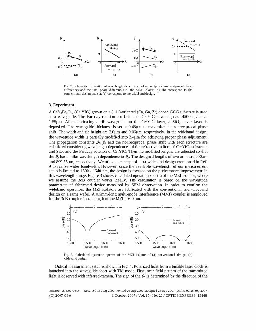
Fig. 2. Schematic illustration of wavelength dependence of nonreciprocal and reciprocal phase differences and the total phase differences of the MZI isolator. (a), (b) correspond to the conventional design and (c), (d) correspond to the wideband design.
3. Experiment
A CeY2Fe5O12 (Ce:YIG) grown on a (111)-oriented (Ca, Ga, Zr) doped GGG substrate is used as a waveguide. The Faraday rotation coefficient of Ce:YIG is as high as -4500deg/cm at 1.55μm. After fabricating a rib waveguide on the Ce:YIG layer, a SiO2 cover layer is deposited. The waveguide thickness is set at 0.48μm to maximize the nonreciprocal phase shift. The width and rib height are 2.0μm and 0.06μm, respectively. In the wideband design, the waveguide width is partially modified into 2.4μm for achieving proper phase adjustment. The propagation constants β1, β2 and the nonreciprocal phase shift with each structure are calculated considering wavelength dependences of the refractive indices of Ce:YIG, substrate, and SiO2 and the Faraday rotation of Ce:YIG. Then the modified lengths are adjusted so that the θR has similar wavelength dependence to θN. The designed lengths of two arms are 900μm and 899.55μm, respectively. We utilize a concept of ultra-wideband design mentioned in Ref. 9 to realize wider bandwidth. However, since the available wavelength of our measurement setup is limited to 1500 - 1640 nm, the design is focused on the performance improvement in this wavelength range. Figure 3 shows calculated operation spectra of the MZI isolator, where we assume the 3dB coupler works ideally. The calculation is based on the waveguide parameters of fabricated device measured by SEM observation. In order to confirm the wideband operation, the MZI isolators are fabricated with the conventional and wideband design on a same wafer. A 0.5mm-long multi-mode interference (MMI) coupler is employed for the 3dB coupler. Total length of the MZI is 6.0mm.
1500 1550 1600 1650
0
10
20
30
40
50
wavelength (nm)
loss
(dB
)
forward backward
1500 1550 1600 1650
0
10
20
30
40
50
wavelength (nm)
loss
(dB
)
forward backward
Fig. 3. Calculated operation spectra of the MZI isolator of (a) conventional design, (b) wideband design.
Optical measurement setup is shown in Fig. 4. Polarized light from a tunable laser diode is
launched into the waveguide facet with TM mode. First, near field pattern of the transmitted light is observed with infrared-camera. The sign of the θN is determined by the direction of the
λ −π/2
π/2
0
θ
θΝ
−θΝ
θR
λ
π
0
θ
=θΝ+θR
λ −π/2
π/2
3π/2
0
θ
θΝ
−θΝ
θR
λ
π
2π
0
θ
Forward
Backward
=−θΝ+θR
=θΝ+θR Forward
Backward =−θΝ+θR
(a) (b) (c) (d)
(a) (b)
#86506 - $15.00 USD Received 15 Aug 2007; revised 26 Sep 2007; accepted 26 Sep 2007; published 28 Sep 2007
(C) 2007 OSA 1 October 2007 / Vol. 15, No. 20 / OPTICS EXPRESS 13448

applied magnetic field. The MZI has three output waveguides, center one as a fiber coupled port and two side ones as radiation ports. A permanent magnet with three poles is set on the waveguide to apply an external magnetic field in anti-parallel directions to obtain a nonreciprocal phase shift. Inverse push-pull operations as shown in Fig. 5 are observed in each design. This agrees with the operation principle as shown in Fig. 1.
Next, fixing the permanent magnet, transmitted light from the center waveguide is coupled into another fiber. Figure 6 shows the transmission loss of the MZI isolators measured with an optical power monitor for the forward and backward propagation direction. The propagation direction is reversed by interchanging the input and output port. The vertical axis is normalized with the transmission loss of a reference waveguide fabricated beside the isolator. The insertion loss measured in the reference waveguide is about 35dB, which includes the propagation loss of 5dB mainly dominated by the optical absorption of Ce:YIG and coupling losses of 30dB at two facets between fiber and waveguide. The measured results agree with the calculated ones qualitatively, though the backward loss is not so much as the calculation results. Deteriorated backward loss measured in the fabricated devices is attributable to the following. The extinction of interferometer, i.e., the backward loss of fabricated devices, is limited by the power imbalance as well as the deviation of phase difference from π between two arms. Also, the maximum sensitivity of the measurement setup is ~70 dB. The scattered data of backward loss measured at a shorter wavelength region are due to this, because the insertion loss of the reference waveguide is larger at the shorter wavelength. The degradation of forward loss in Fig. 6(a) is not due to the design but the accuracy of fabrication. That is, the coupling loss between fiber and waveguide or the propagation loss of the sample in Fig. 6(a) is larger than those of the sample in (b) accidentally. The difference in the transmission loss between the forward and backward direction corresponds to the isolation ratio. Larger isolation ratio is obtained in a wider wavelength range in the wideband design. High isolation ratio of 15-25dB is observed in a wavelength range between 1530nm and 1640nm in the wideband isolator.
Fig. 4. Optical measurement setup for MZI isolator
Fig. 5. Near field patterns of transmitted light with an ASE light source having an optical gain around λ= 1.55μm. The MZI isolators are fabricated with (a), (b) conventional design and (c), (d) wideband design on a same wafer.
Tunable LD N
S
S
Optical Power Meter
PMF PMF
TM mode
IR camera
Polarizer
Monitor
Changing the optical direction
Sample
Permanent magnet
(a) magnet: S-N-S (b) magnet: N-S-N (c) magnet: S-N-S (d) magnet: N-S-N
#86506 - $15.00 USD Received 15 Aug 2007; revised 26 Sep 2007; accepted 26 Sep 2007; published 28 Sep 2007
(C) 2007 OSA 1 October 2007 / Vol. 15, No. 20 / OPTICS EXPRESS 13449

1500 1550 1600 1650
0
10
20
30
wavelength (nm)
loss
(dB
) forward backward
1500 1550 1600 1650
0
10
20
30
wavelength (nm)
loss
(dB
)
forward backward
Fig. 6. Measured transmission of the MZI isolator of (a) conventional design and (b) wideband design.
4. Conclusion
A wideband operation of Mach-Zehnder interferometric magneto-optical isolator is demonstrated. The operation is realized by tailoring the waveguide parameter, such as the width and length, to adjust the wavelength dependence of the phase difference. High isolation ratio of 15-25dB is observed in a wide wavelength range.
(a) (b)
#86506 - $15.00 USD Received 15 Aug 2007; revised 26 Sep 2007; accepted 26 Sep 2007; published 28 Sep 2007
(C) 2007 OSA 1 October 2007 / Vol. 15, No. 20 / OPTICS EXPRESS 13450