Embed Size (px)
Citation preview
Wind 25.2+
Manual Versión 1.5 – 07.17
Montaje
Installation
Operación Operation
Mantenimiento Maintenance
ENG
ESP
2
Índice
Índice 2
Bienvenidos al mundo del viento 3
Componentes del aerogenerador 5
Datos técnicos 6
Emplazamiento del aerogenerador 8
Montaje 8
La Torre 9
Cableado eléctrico 11
Montaje del aerogenerador 12
Mantenimiento 17
Preguntas frecuentes 19
Anexos 21
Declaración de conformidad 23
Garantía 24
Bornay Aerogeneradores SLU P.I. Riu, Camino del Riu, s/n Tel. +34/965560025 [email protected] 03420 Castalla (Alicante) España Fax +34/965560752 www.bornay.com
ESP
4
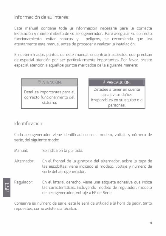
Información de su interés: Este manual contiene toda la información necesaria para la correcta instalación y mantenimiento de su aerogenerador. Para asegurar su correcto funcionamiento, evitar roturas y peligros, se recomienda que lea atentamente este manual antes de proceder a realizar la instalación. En determinados puntos de este manual encontrará aspectos que precisan de especial atención por ser particularmente importantes. Por favor, preste especial atención a aquellos puntos marcados de la siguiente manera:
ATENCIÓN: PRECAUCIÓN:
Detalles importantes para el correcto funcionamiento del
sistema.
Detalles a tener en cuenta para evitar daños
irreparables en su equipo o a personas.
Identificación: Cada aerogenerador viene identificado con el modelo, voltaje y número de serie, del siguiente modo: Manual: Se indica en la portada. Alternador: En el frontal de la giratoria del alternador, sobre la tapa de
las escobillas, viene indicado el modelo, voltaje y número de serie del aerogenerador.
Regulador: En el lateral derecho, viene una etiqueta adhesiva que indica
las características, incluyendo modelo de regulador, modelo de aerogenerador, voltaje y Nº de Serie.
Conserve su número de serie, este le será de utilidad a la hora de pedir, tanto repuestos, como asistencia técnica.
ESP
5
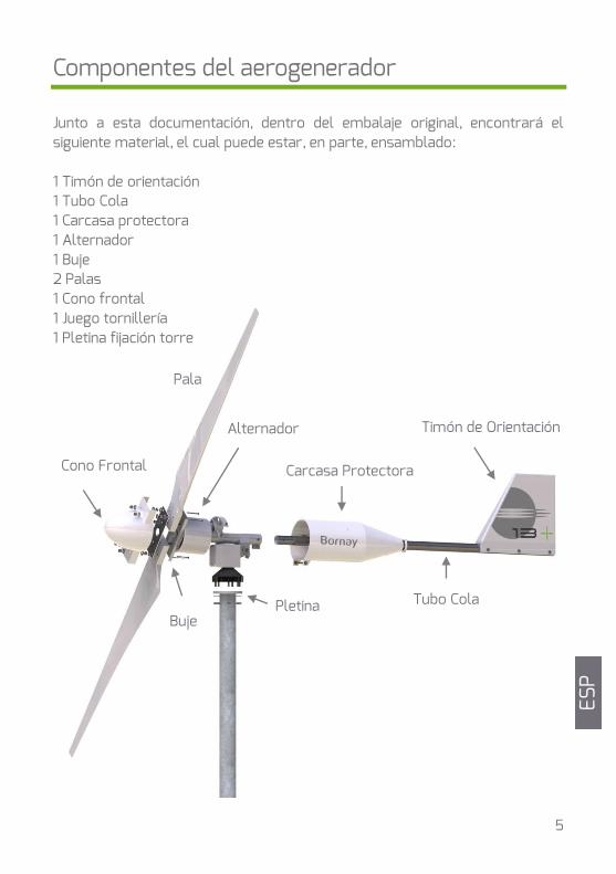
Componentes del aerogenerador Junto a esta documentación, dentro del embalaje original, encontrará el siguiente material, el cual puede estar, en parte, ensamblado: 1 Timón de orientación 1 Tubo Cola 1 Carcasa protectora 1 Alternador 1 Buje 2 Palas 1 Cono frontal 1 Juego tornillería 1 Pletina fijación torre
Timón de Orientación
Carcasa Protectora
Buje
Cono Frontal
Tubo Cola Pletina
Alternador
Pala
ESP
6
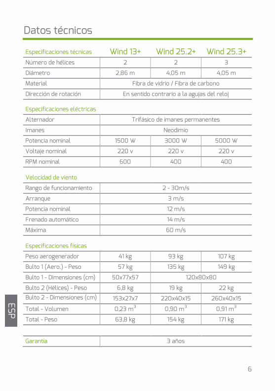
Datos técnicos
Wind 13+ Wind 25.2+ Wind 25.3+ Especificaciones técnicas
Número de hélices 2 2 3
Diámetro 2,86 m 4,05 m 4,05 m
Material Fibra de vidrio / Fibra de carbono
Dirección de rotación En sentido contrario a la agujas del reloj
Especificaciones eléctricas
Alternador Trifásico de imanes permanentes
Imanes Neodimio
Potencia nominal 1500 W 3000 W 5000 W
Voltaje nominal 220 v 220 v 220 v
RPM nominal 600 400 400
Velocidad de viento
Rango de funcionamiento 2 - 30m/s
Arranque 3 m/s
Potencia nominal 12 m/s
Frenado automático 14 m/s
Máxima 60 m/s
Especificaciones físicas
Peso aerogenerador 41 kg 93 kg 107 kg
Bulto 1 (Aero.) - Peso 57 kg 135 kg 149 kg
Bulto 1 - Dimensiones (cm) 50x77x57 120x80x80
Bulto 2 (Hélices) - Peso 6,8 kg 19 kg 22 kg Bulto 2 - Dimensiones (cm) 153x27x7 220x40x15 260x40x15
Total - Volumen 0,23 m3 0,90 m3 0,91 m3
Total - Peso 63,8 kg 154 kg 171 kg
Garantía 3 años
ESP
7
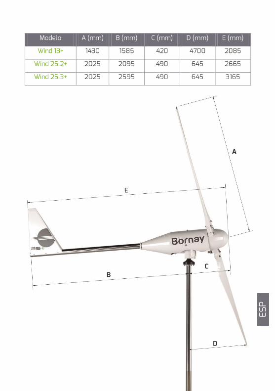
Modelo A (mm) B (mm) C (mm) D (mm) E (mm)
Wind 13+ 1430 1585 420 4700 2085
Wind 25.2+ 2025 2095 490 645 2665
Wind 25.3+ 2025 2595 490 645 3165
ESP
8
Montaje de la torre
Cableado eléctrico
controlador
Montaje del aero-
generador
Pruebas de funciona-
miento
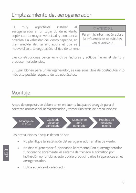
Emplazamiento del aerogenerador Es muy importante instalar el aerogenerador en un lugar donde el viento sople con la mayor velocidad y constancia posibles. La velocidad del viento depende, en gran medida, del terreno sobre el que se mueve el aire, la vegetación, el tipo de terreno, Las construcciones cercanas y otros factores y sólidos frenan el viento y producen turbulencias. El lugar idóneo para un aerogenerador, es una zona libre de obstáculos y lo más alto posible respecto de los obstáculos.
Montaje Antes de empezar, se deben tener en cuenta los pasos a seguir para el correcto montaje del aerogenerador y tomar una serie de precauciones: Las precauciones a seguir deben de ser:
No planifique la instalación del aerogenerador en días de viento.
No deje el generador funcionando libremente. Con el aerogenerador funcionando libremente, el sistema de frenado automático por inclinación no funciona, esto podría producir daños irreparables en el aerogenerador.
Utilice el cableado adecuado.
ATENCIÓN:
Para más información sobre la influencia de obstáculos
vea el Anexo 2.
ESP
9
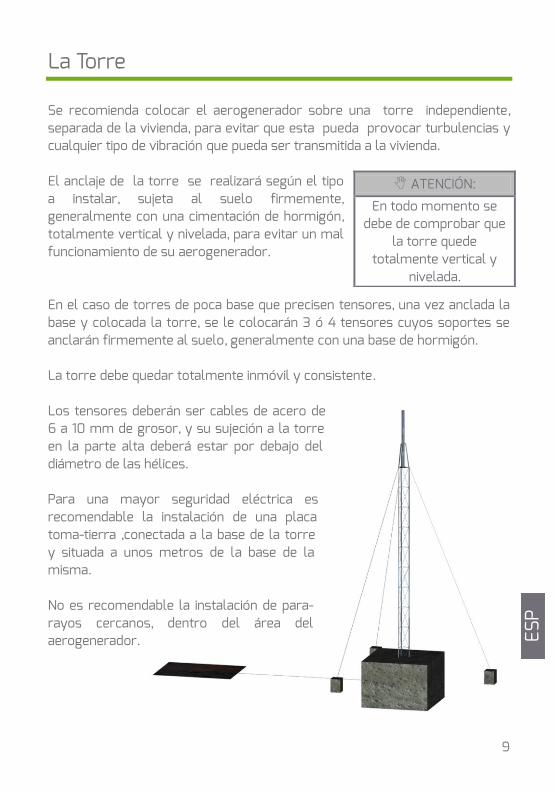
La Torre Se recomienda colocar el aerogenerador sobre una torre independiente, separada de la vivienda, para evitar que esta pueda provocar turbulencias y cualquier tipo de vibración que pueda ser transmitida a la vivienda. El anclaje de la torre se realizará según el tipo a instalar, sujeta al suelo firmemente, generalmente con una cimentación de hormigón, totalmente vertical y nivelada, para evitar un mal funcionamiento de su aerogenerador. En el caso de torres de poca base que precisen tensores, una vez anclada la base y colocada la torre, se le colocarán 3 ó 4 tensores cuyos soportes se anclarán firmemente al suelo, generalmente con una base de hormigón. La torre debe quedar totalmente inmóvil y consistente. Los tensores deberán ser cables de acero de 6 a 10 mm de grosor, y su sujeción a la torre en la parte alta deberá estar por debajo del diámetro de las hélices. Para una mayor seguridad eléctrica es recomendable la instalación de una placa toma-tierra ,conectada a la base de la torre y situada a unos metros de la base de la misma. No es recomendable la instalación de para-rayos cercanos, dentro del área del aerogenerador.
ATENCIÓN:
En todo momento se debe de comprobar que
la torre quede totalmente vertical y
nivelada.
ESP
10
ATENCIÓN: PRECAUCIÓN:
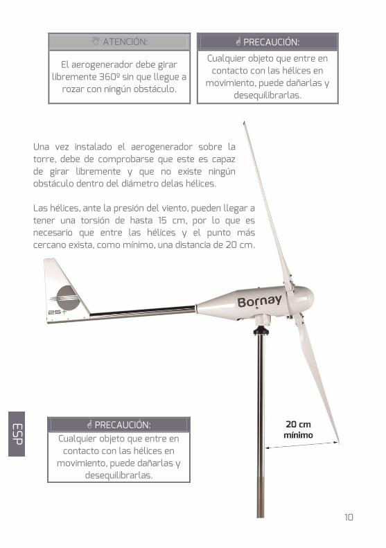
El aerogenerador debe girar libremente 360º sin que llegue a
rozar con ningún obstáculo.
Cualquier objeto que entre en contacto con las hélices en
movimiento, puede dañarlas y desequilibrarlas.
Una vez instalado el aerogenerador sobre la torre, debe de comprobarse que este es capaz de girar libremente y que no existe ningún obstáculo dentro del diámetro delas hélices. Las hélices, ante la presión del viento, pueden llegar a tener una torsión de hasta 15 cm, por lo que es necesario que entre las hélices y el punto más cercano exista, como mínimo, una distancia de 20 cm.
PRECAUCIÓN: Cualquier objeto que entre en
contacto con las hélices en movimiento, puede dañarlas y
desequilibrarlas.
ESP
11
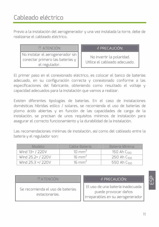
Cableado eléctrico Previo a la instalación del aerogenerador y una vez instalada la torre, debe de realizarse el cableado eléctrico.
ATENCIÓN: PRECAUCIÓN: No instalar el aerogenerador sin conectar primero las baterías y
el regulador.
No invertir la polaridad. Utilice el cableado adecuado.
El primer paso en el conexionado eléctrico, es colocar el banco de baterías adecuado, en su configuración correcta y conexionado conforme a las especificaciones del fabricante, obteniendo como resultado el voltaje y capacidad adecuados para la instalación que vamos a realizar. Existen diferentes tipologías de baterías. En el caso de instalaciones domésticas hibridas eólico / solares, se recomienda el uso de baterías de plomo ácido abiertas y en función de las capacidades de carga de la instalación, se precisan de unos requisitos mínimos de instalación para asegurar el correcto funcionamiento y la durabilidad de la instalación. Las recomendaciones mínimas de instalación, así como del cableado entre la batería y el regulador son:
Modelo Cable Batería Batería Mínima Wind 13+ / 220V 10 mm2 150 Ah C100 Wind 25.2+ / 220V 16 mm2 250 Ah C100 Wind 25.3 +/ 220V 16 mm2 550 Ah C100
ATENCIÓN: PRECAUCIÓN:
Se recomienda el uso de baterías estacionarías.
El uso de una batería inadecuada puede provocar daños
irreparables en su aerogenerador
GB
ESP
GB
GB
12
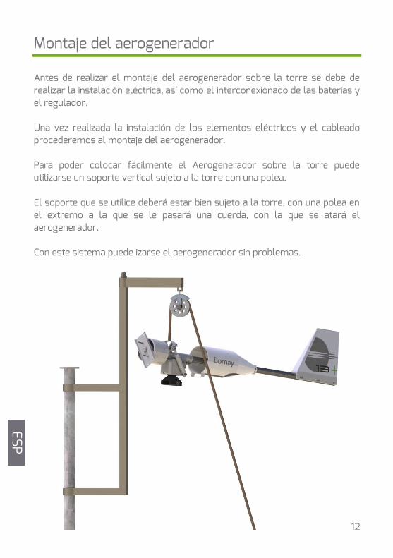
Montaje del aerogenerador
Antes de realizar el montaje del aerogenerador sobre la torre se debe de realizar la instalación eléctrica, así como el interconexionado de las baterías y el regulador. Una vez realizada la instalación de los elementos eléctricos y el cableado procederemos al montaje del aerogenerador. Para poder colocar fácilmente el Aerogenerador sobre la torre puede utilizarse un soporte vertical sujeto a la torre con una polea. El soporte que se utilice deberá estar bien sujeto a la torre, con una polea en el extremo a la que se le pasará una cuerda, con la que se atará el aerogenerador. Con este sistema puede izarse el aerogenerador sin problemas.
ESP
13
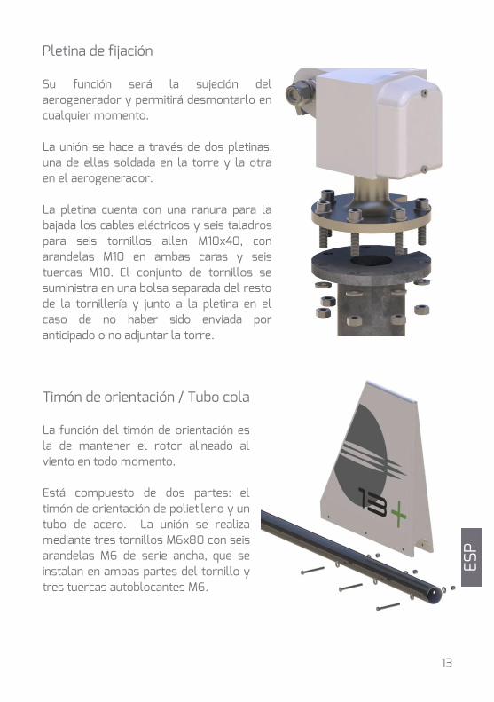
Pletina de fijación Su función será la sujeción del aerogenerador y permitirá desmontarlo en cualquier momento. La unión se hace a través de dos pletinas, una de ellas soldada en la torre y la otra en el aerogenerador. La pletina cuenta con una ranura para la bajada los cables eléctricos y seis taladros para seis tornillos allen M10x40, con arandelas M10 en ambas caras y seis tuercas M10. El conjunto de tornillos se suministra en una bolsa separada del resto de la tornillería y junto a la pletina en el caso de no haber sido enviada por anticipado o no adjuntar la torre.
Timón de orientación / Tubo cola La función del timón de orientación es la de mantener el rotor alineado al viento en todo momento. Está compuesto de dos partes: el timón de orientación de polietileno y un tubo de acero. La unión se realiza mediante tres tornillos M6x80 con seis arandelas M6 de serie ancha, que se instalan en ambas partes del tornillo y tres tuercas autoblocantes M6.
ESP
14
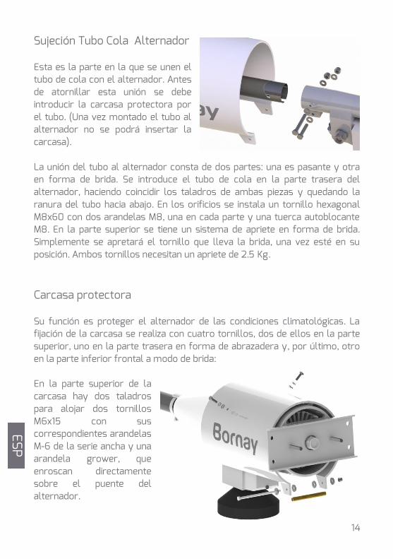
Sujeción Tubo Cola Alternador Esta es la parte en la que se unen el tubo de cola con el alternador. Antes de atornillar esta unión se debe introducir la carcasa protectora por el tubo. (Una vez montado el tubo al alternador no se podrá insertar la carcasa). La unión del tubo al alternador consta de dos partes: una es pasante y otra en forma de brida. Se introduce el tubo de cola en la parte trasera del alternador, haciendo coincidir los taladros de ambas piezas y quedando la ranura del tubo hacia abajo. En los orificios se instala un tornillo hexagonal M8x60 con dos arandelas M8, una en cada parte y una tuerca autoblocante M8. En la parte superior se tiene un sistema de apriete en forma de brida. Simplemente se apretará el tornillo que lleva la brida, una vez esté en su posición. Ambos tornillos necesitan un apriete de 2.5 Kg.
Carcasa protectora Su función es proteger el alternador de las condiciones climatológicas. La fijación de la carcasa se realiza con cuatro tornillos, dos de ellos en la parte superior, uno en la parte trasera en forma de abrazadera y, por último, otro en la parte inferior frontal a modo de brida: En la parte superior de la carcasa hay dos taladros para alojar dos tornillos M6x15 con sus correspondientes arandelas M-6 de la serie ancha y una arandela grower, que enroscan directamente sobre el puente del alternador.
ESP
15
El orden de instalación es: tornillo, arandela grower, arandela de serie ancha. A continuación se ha de apretar el tornillo de la abrazadera de la parte posterior de la carcasa. Por último, en la parte frontal inferior, en las dos pestañas conformadas a modo de brida, se instala el tubo de latón, de 102 mm de longitud y un diámetro exterior de 10 mm, un tornillo M6 x 120 y con una arandela M6 serie ancha por cada parte. El conjunto se alojará en la zona interior de la carcasa, entre las dos pestañas. Para finalizar, instale una nueva arandela y la tuerca de seguridad autoblocante.
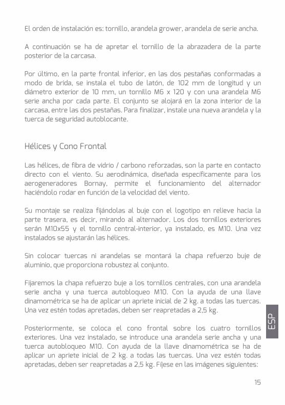
Hélices y Cono Frontal Las hélices, de fibra de vidrio / carbono reforzadas, son la parte en contacto directo con el viento. Su aerodinámica, diseñada específicamente para los aerogeneradores Bornay, permite el funcionamiento del alternador haciéndolo rodar en función de la velocidad del viento. Su montaje se realiza fijándolas al buje con el logotipo en relieve hacia la parte trasera, es decir, mirando al alternador. Los dos tornillos exteriores serán M10x55 y el tornillo central-interior, ya instalado, es M10. Una vez instalados se ajustarán las hélices. Sin colocar tuercas ni arandelas se montará la chapa refuerzo buje de aluminio, que proporciona robustez al conjunto. Fijaremos la chapa refuerzo buje a los tornillos centrales, con una arandela serie ancha y una tuerca autobloqueo M10. Con la ayuda de una llave dinamométrica se ha de aplicar un apriete inicial de 2 kg. a todas las tuercas. Una vez estén todas apretadas, deben ser reapretadas a 2,5 kg. Posteriormente, se coloca el cono frontal sobre los cuatro tornillos exteriores. Una vez instalado, se introduce una arandela serie ancha y una tuerca autobloqueo M10. Con ayuda de la llave dinamométrica se ha de aplicar un apriete inicial de 2 kg. a todas las tuercas. Una vez estén todas apretadas, deben ser reapretadas a 2,5 kg. Fíjese en las imágenes siguientes:
ESP
16
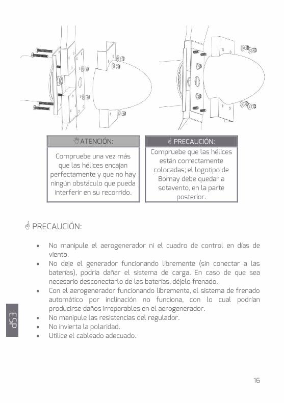
ATENCIÓN: PRECAUCIÓN:
Compruebe una vez más que las hélices encajan
perfectamente y que no hay ningún obstáculo que pueda
interferir en su recorrido.
Compruebe que las hélices están correctamente
colocadas; el logotipo de Bornay debe quedar a sotavento, en la parte
posterior.
PRECAUCIÓN:
No manipule el aerogenerador ni el cuadro de control en días de viento.
No deje el generador funcionando libremente (sin conectar a las baterías), podría dañar el sistema de carga. En caso de que sea necesario desconectarlo de las baterías, déjelo frenado.
Con el aerogenerador funcionando libremente, el sistema de frenado automático por inclinación no funciona, con lo cual podrían producirse daños irreparables en el aerogenerador.
No manipule las resistencias del regulador. No invierta la polaridad. Utilice el cableado adecuado.
ES
P
ESP
17
Mantenimiento
Tras su instalación Transcurrido 1 mes desde la instalación del aerogenerador, se recomienda reapretar toda la tornillería del aerogenerador. Permanente Para asegurar la vida de su aerogenerador, se aconseja que siga los siguientes consejos de mantenimiento: Cada 6 meses A ser posible en los cambios de estación, se recomienda realizar una inspección de mantenimiento en la que se deben de revisar los siguientes puntos:
Revisar y reapretar todos los tornillos. Comprobar el estado de los cables. Inspección visual de las hélices. Revisión del sistema de frenado automático, accionando este
manualmente. Las partes principales del aerogenerador a la hora de realizar las inspecciones de mantenimiento son:
Rodamientos El aerogenerador está equipado con rodamientos blindados de gran calidad que no necesitan mantenimiento. Puede comprobar si giran libremente o si, por el contrario, se observa algún tipo de roce o vibración.
Tornillería Toda la tornillería es de acero inoxidable. Ante la falta de cualquier tornillo en una revisión de mantenimiento, debe reemplazarse inmediatamente, antes de que pueda producir daños mayores.
ESP
18
Cableado Comprobar el estado de las uniones y empalmes, así como las regletas de las conexiones que haya, para evitar que pueda desconectarse y dejar el aerogenerador funcionando libremente.
Hélices Las hélices de fibra de vidrio / carbono, llevan en el borde de ataque una cinta protectora de Poliuretano abrasivo. Esta cinta con el paso del tiempo puede verse afectada por las condiciones climatológicas. En caso de falta total ó parcial de la cinta, acuda a su instalador y reemplace la cinta. En caso contrario, la erosión y cambios climáticos incidirán directamente sobre la hélice, reduciendo su vida útil.
Amortiguador El aerogenerador lleva instalado un amortiguador hidráulico que permite la desorientación respecto al viento rápidamente, y su vuelta a la posición normal lenta, evitando golpes bruscos. El amortiguador tiene una pequeña holgura al principio de su retroceso que es normal. Si su holgura fuera mayor de la mitad del recorrido y se observan pérdidas de aceite, habría que sustituir los amortiguadores por unos nuevos.
Engrase El aerogenerador Wind + consta de 3 partes móviles: El eje delantero (Hélice-alternador), provisto de rodamientos blindados y recubiertos totalmente con una grasa de por vida. No precisan engrase. El eje de orientación (aerogenerador-torre), provisto con rodamientos blindados. No precisan engrase. El eje de inclinación (alternador-giratoria), es un casquillo de acero inoxidable / bronce engrasado de por vida.
ESP
19
Preguntas frecuentes 1.- ¿ Importa la polaridad de los cables del aerogenerador? No, la bajada del aerogenerador es trifásica alterna, por lo tanto estos pueden conectarse sin ningún tipo de orden. 2.- ¿Cómo se puede saber la potencia que está entregando el aerogenerador? La potencia se puede saber mediante la pantalla o con el software específico de Bornay. 3.- ¿Pueden estar mal los orificios de las hélices? Negativo. Cada aerogenerador se ensambla completamente en producción. Si no coinciden los taladros pruebe a dar la vuelta a las hélices. El modelo Wind 13+ tienen 3 taladros y los Wind 25.2+ y Wind 25.3+ tienen ambos 5, de los cuales hay uno desplazado respecto al centro para definir la correcta instalación de las hélices. 4.- ¿Se puede alimentar una casa con estos aerogeneradores? Este tipo de aerogenerador se usa, normalmente, junto con otros componentes para formar una instalación completa. Estos componentes suelen ser:
Paneles solares: producción de energía. Reguladores solares: para controlar la carga de las baterías desde
los paneles solares. Baterías (Acumulación de dicha energía): normalmente se diseñan las
instalaciones para que tengan 3 días de autonomía, es decir, que puedan dar suministro a la instalación durante 3 días sin viento ni sol. Son de corriente continua.
Regulador eólico: va incluido con el aerogenerador y es el que se encarga de vigilar la vida de la batería. Se encarga de que el voltaje de la betería no sobrepase unos valores peligrosos. Al mismo tiempo, se encarga de frenar la máquina cuando esto ocurre.
ESP
20
Inversor/Cargador: es el equipo que se encarga de transformar la corriente continua de las baterías en corriente alterna apta para el consumo (230V~).
Generador de apoyo.: en una instalación aislada completa se instala para garantizar el completo funcionamiento autónomo de la instalación. Normalmente, el inversor se encargará de maniobrar el arranque y paro del motor en función de las necesidades de la instalación. Por ejemplo, si el nivel de batería baja, el inversor ordena al motor que arranque.
5.- ¿Se pueden poner varios aerogeneradores en paralelo? Sí, se pueden poner varios aerogeneradores en paralelo. 6.- ¿Cómo es la tensión que genera el alternador? El aerogenerador saca una señal trifásica alterna con voltaje nominal de aproximadamente 230V. 7.- ¿Se debe de instalar algún tipo de protección entre el aerogenerador y el regulador-interface o entre estos y la batería? Nunca. El regulador o interface ya realizan estas funciones de protección. En caso de instalar una protección intermedia y que esta desconecte la conexión eléctrica, el aerogenerador quedaría libre, sin carga, y esto puede producir daños irreparables en su aerogenerador o regulador/interface. 8.- ¿Se debe instalar un interruptor de freno auxiliar?
No es necesario, pero puede ser recomendable en las instalaciones donde se quiera detener el aerogenerador por completo, con el fin de hacer alguna intervención en el/los equipos.
ESP
21
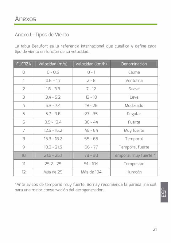
Anexos Anexo I.- Tipos de Viento La tabla Beaufort es la referencia internacional que clasifica y define cada tipo de viento en función de su velocidad.
FUERZA Velocidad (m/s) Velocidad (km/h) Denominación
0 0 - 0.5 0 - 1 Calma
1 0.6 – 1.7 2 - 6 Ventolina
2 1.8 - 3.3 7 - 12 Suave
3 3.4 - 5.2 13 - 18 Leve
4 5.3 - 7.4 19 - 26 Moderado
5 5.7 - 9.8 27 - 35 Regular
6 9.9 - 10.4 36 - 44 Fuerte
7 12.5 - 15.2 45 - 54 Muy fuerte
8 15.3 - 18.2 55 - 65 Temporal
9 18.3 - 21.5 66 - 77 Temporal fuerte
10 21.6 - 25.1 78 - 90 Temporal muy fuerte *
11 25.2 - 29 91 - 104 Tempestad
12 Más de 29 Más de 104 Huracán
*Ante avisos de temporal muy fuerte, Bornay recomienda la parada manual para una mejor conservación del aerogenerador. ES
P
22
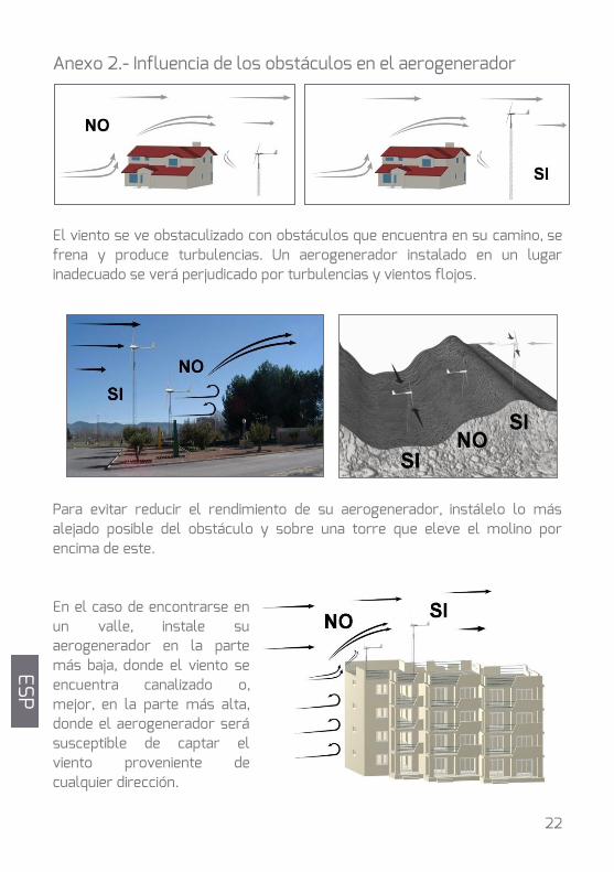
Anexo 2.- Influencia de los obstáculos en el aerogenerador
El viento se ve obstaculizado con obstáculos que encuentra en su camino, se frena y produce turbulencias. Un aerogenerador instalado en un lugar inadecuado se verá perjudicado por turbulencias y vientos flojos.
Para evitar reducir el rendimiento de su aerogenerador, instálelo lo más alejado posible del obstáculo y sobre una torre que eleve el molino por encima de este. En el caso de encontrarse en un valle, instale su aerogenerador en la parte más baja, donde el viento se encuentra canalizado o, mejor, en la parte más alta, donde el aerogenerador será susceptible de captar el viento proveniente de cualquier dirección.
ESP
24
Garantía
GARANTÍA LIMITADA Su nuevo Aerogenerador de la serie Wind + están garantizados contra todo defecto en materiales y mano de obra. Esta garantía no cubre daños a otros equipos y / o accesorios que pudieran verse involucrados en la reparación del aerogenerador. La garantía tampoco incluye daños causados por una realización indebida de la instalación o un uso indebido del producto. PERÍODO DE GARANTÍA – AEROGENERADORES WIND + El período de garantía de los Aerogeneradores Wind + y sus componentes es de 36 meses desde la fecha de instalación o de 40 meses desde la fecha de fabricación. ACCESORIOS AEROGENERADORES WIND + El período de garantía de los Accesorios Bornay es de 36 meses desde la fecha de instalación o de 40 meses desde la fecha de fabricación. CONDICIONES DE LA GARANTÍA La garantía incluye piezas y mano de obra, siempre en nuestros talleres, debiendo enviarnos el aerogenerador debidamente embalado y siempre a portes pagados.
La garantía excluye roturas por malos tratos, equipos con muestras de manipulación y portes.
Bornay se reserva el derecho de poder sustituir o modificar cualquier pieza en caso oportuno.
Todo Aerogenerador que no cumpla estas condiciones, será reparado y enviado, cargando el valor de la reparación, previa autorización del cliente. Bornay Aerogeneradores, S.L.U
ESP
25
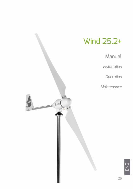
Wind 25.2+
Manual
Installation
Operation
Maintenance
ENG
ENG
26
Index
Index 26
Welcome to the world of the wind 27
Wind Turbine Components 29
Datasheet 30
Placing your wind turbine 32
Installation 32
The Tower 33
Electrical wiring 35
Installing the Wind Turbine 36
Maintenance 41
Frequently ask questions 43
Annex 45
Declaration of conformity 47
Warranty 47
ENG
28
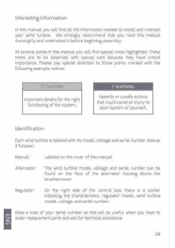
Interesting information In this manual you will find all the information needed to install and maintain your wind turbine. We strongly recommend that you read this manual thoroughly and understand it before beginning assembly. At several points in this manual you will find special notes highlighted. These notes are to be observed with special care because they have critical importance. Please pay special attention to those points marked with the following example notices:
CAUTION: WARNING:
Important details for the right functioning of the system.
Hazards or unsafe actions that could cause an injury to
your system or yourself.
Identification Each wind turbine is labeled with its model, voltage and serial number data as it follows: Manual: Labeled on the cover of this manual. Alternator: The wind turbine model, voltage and serial number can be
found on the face of the alternator housing above the brushes cover.
Regulator: On the right side of the control box, there is a sticker
indicating the characteristics, regulator model, wind turbine model, voltage, and serial number.
Keep a note of your serial number as this will be useful when you have to order replacement parts and ask for technical assistance.
ENG
29
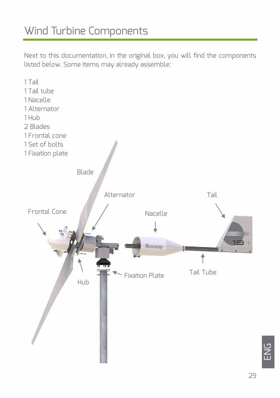
Wind Turbine Components Next to this documentation, in the original box, you will find the components listed below. Some items may already assemble: 1 Tail 1 Tail tube 1 Nacelle 1 Alternator 1 Hub 2 Blades 1 Frontal cone 1 Set of bolts 1 Fixation plate
Tail
Nacelle
Hub
Frontal Cone
Tail Tube Fixation Plate
Alternator
Blade
ENG
30
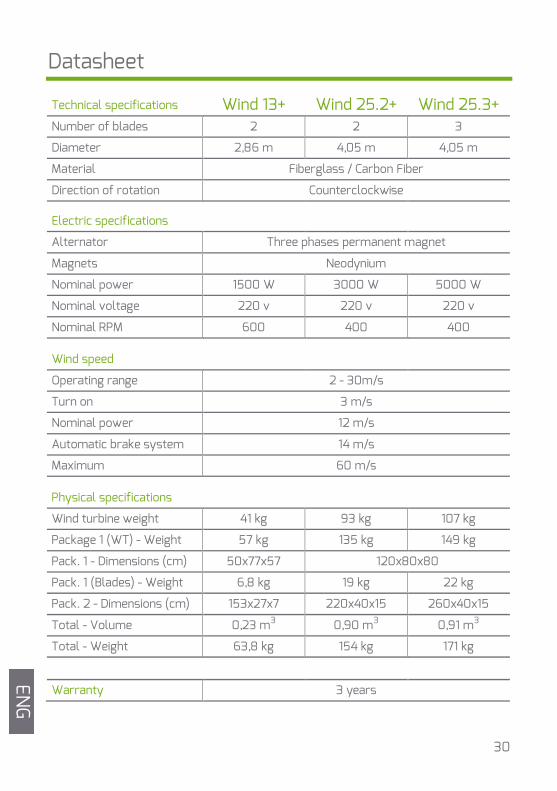
Datasheet
Wind 13+ Wind 25.2+ Wind 25.3+ Technical specifications
Number of blades 2 2 3
Diameter 2,86 m 4,05 m 4,05 m
Material Fiberglass / Carbon Fiber
Direction of rotation Counterclockwise
Electric specifications
Alternator Three phases permanent magnet
Magnets Neodynium
Nominal power 1500 W 3000 W 5000 W
Nominal voltage 220 v 220 v 220 v
Nominal RPM 600 400 400
Wind speed
Operating range 2 - 30m/s
Turn on 3 m/s
Nominal power 12 m/s
Automatic brake system 14 m/s
Maximum 60 m/s
Physical specifications
Wind turbine weight 41 kg 93 kg 107 kg
Package 1 (WT) - Weight 57 kg 135 kg 149 kg
Pack. 1 - Dimensions (cm) 50x77x57 120x80x80
Pack. 1 (Blades) - Weight 6,8 kg 19 kg 22 kg
Pack. 2 - Dimensions (cm) 153x27x7 220x40x15 260x40x15
Total - Volume 0,23 m3 0,90 m3 0,91 m3
Total - Weight 63,8 kg 154 kg 171 kg
Warranty 3 years
ENG
31
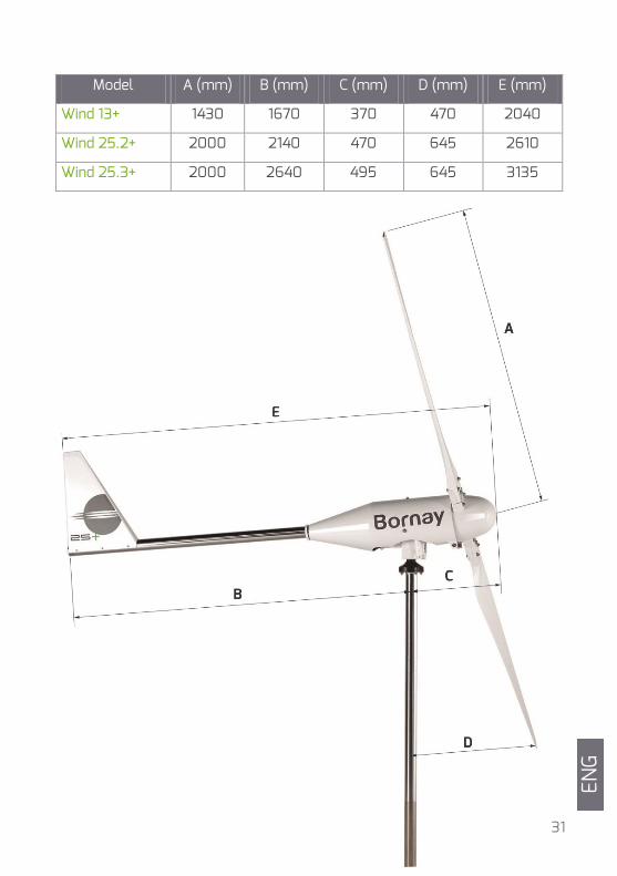
Model A (mm) B (mm) C (mm) D (mm) E (mm)
Wind 13+ 1430 1670 370 470 2040
Wind 25.2+ 2000 2140 470 645 2610
Wind 25.3+ 2000 2640 495 645 3135
ENG
32
Tower installation
Electrical wiring
controler
Windturbine installation
Functionality test
Placing your wind turbine The best site to install a wind turbine will be a place where it is exposed to the most constant and highest wind speed possible. Wind speed depends enormously on the landscape the air moves over. In almost all locations the wind speed increases, as you get higher off the ground; vegetation, landscape, nearby buildings, etc. stop the wind and produce turbulences. The best place for a wind machine, is an obstruction-free area, and at the maximum height available.
Installation Before you begin, run through the steps to follow in order to correctly assemble your wind turbine and take a series of important precautions. . The precautions to follow should be:
Don't plan to carry out installation on windy days.
Do not leave the generator running freely. With the generator running freely, the automatic leaning brake system does not work; this could cause irreparable damage to the wind turbine.
Use the correct wiring.
CAUTION: For more information on obstacles affecting wind
turbines, see Annex 2.
ENG
33
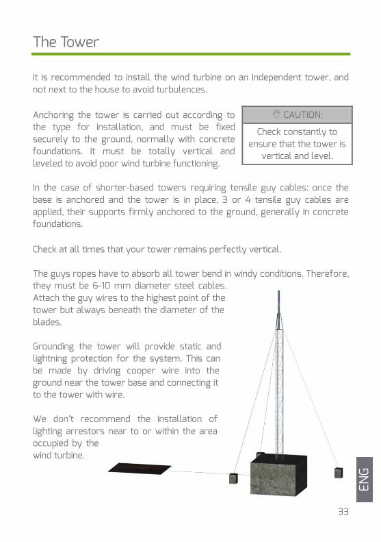
The Tower It is recommended to install the wind turbine on an Independent tower, and not next to the house to avoid turbulences. Anchoring the tower is carried out according to the type for installation, and must be fixed securely to the ground, normally with concrete foundations. It must be totally vertical and leveled to avoid poor wind turbine functioning. In the case of shorter-based towers requiring tensile guy cables: once the base is anchored and the tower is in place, 3 or 4 tensile guy cables are applied, their supports firmly anchored to the ground, generally in concrete foundations. Check at all times that your tower remains perfectly vertical. The guys ropes have to absorb all tower bend in windy conditions. Therefore, they must be 6-10 mm diameter steel cables. Attach the guy wires to the highest point of the tower but always beneath the diameter of the blades. Grounding the tower will provide static and lightning protection for the system. This can be made by driving cooper wire into the ground near the tower base and connecting it to the tower with wire. We don’t recommend the installation of lighting arrestors near to or within the area occupied by the wind turbine.
CAUTION:
Check constantly to ensure that the tower is
vertical and level.
ENG
34
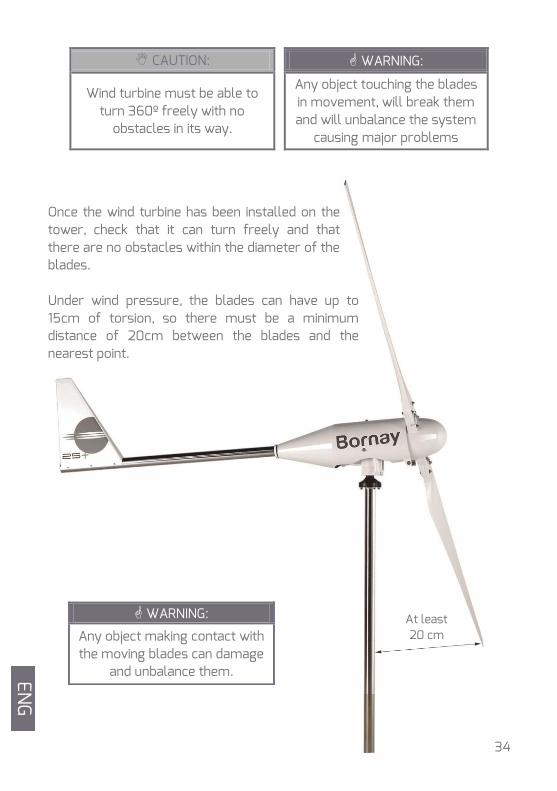
CAUTION: WARNING:
Wind turbine must be able to turn 360º freely with no
obstacles in its way.
Any object touching the blades in movement, will break them and will unbalance the system
causing major problems Once the wind turbine has been installed on the tower, check that it can turn freely and that there are no obstacles within the diameter of the blades. Under wind pressure, the blades can have up to 15cm of torsion, so there must be a minimum distance of 20cm between the blades and the nearest point.
WARNING:
Any object making contact with the moving blades can damage
and unbalance them.
At least 20 cm
ENG
35
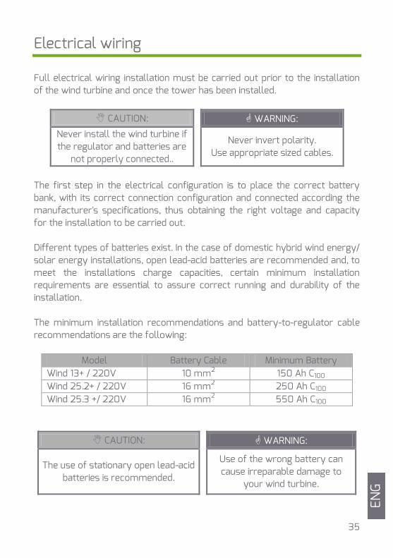
Electrical wiring Full electrical wiring installation must be carried out prior to the installation of the wind turbine and once the tower has been installed.
CAUTION: WARNING: Never install the wind turbine if the regulator and batteries are
not properly connected..
Never invert polarity. Use appropriate sized cables.
The first step in the electrical configuration is to place the correct battery bank, with its correct connection configuration and connected according the manufacturer's specifications, thus obtaining the right voltage and capacity for the installation to be carried out. Different types of batteries exist. In the case of domestic hybrid wind energy/ solar energy installations, open lead-acid batteries are recommended and, to meet the installations charge capacities, certain minimum installation requirements are essential to assure correct running and durability of the installation. The minimum installation recommendations and battery-to-regulator cable recommendations are the following:
Model Battery Cable Minimum Battery Wind 13+ / 220V 10 mm2 150 Ah C100 Wind 25.2+ / 220V 16 mm2 250 Ah C100 Wind 25.3 +/ 220V 16 mm2 550 Ah C100
CAUTION: WARNING:
The use of stationary open lead-acid batteries is recommended.
Use of the wrong battery can cause irreparable damage to
your wind turbine.
GB
GB
ENG
36
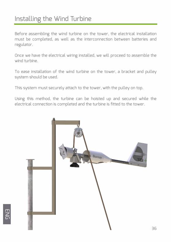
Installing the Wind Turbine Before assembling the wind turbine on the tower, the electrical installation must be completed, as well as the interconnection between batteries and regulator. Once we have the electrical wiring installed, we will proceed to assemble the wind turbine. To ease installation of the wind turbine on the tower, a bracket and pulley system should be used. This system must securely attach to the tower, with the pulley on top. Using this method, the turbine can be hoisted up and secured while the electrical connection is completed and the turbine is fitted to the tower.
EN
G
37
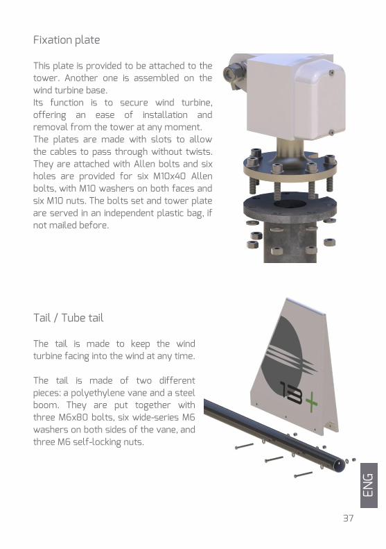
Fixation plate This plate is provided to be attached to the tower. Another one is assembled on the wind turbine base. Its function is to secure wind turbine, offering an ease of installation and removal from the tower at any moment. The plates are made with slots to allow the cables to pass through without twists. They are attached with Allen bolts and six holes are provided for six M10x40 Allen bolts, with M10 washers on both faces and six M10 nuts. The bolts set and tower plate are served in an independent plastic bag, if not mailed before.
Tail / Tube tail The tail is made to keep the wind turbine facing into the wind at any time. The tail is made of two different pieces: a polyethylene vane and a steel boom. They are put together with three M6x80 bolts, six wide-series M6 washers on both sides of the vane, and three M6 self-locking nuts.
ENG
38
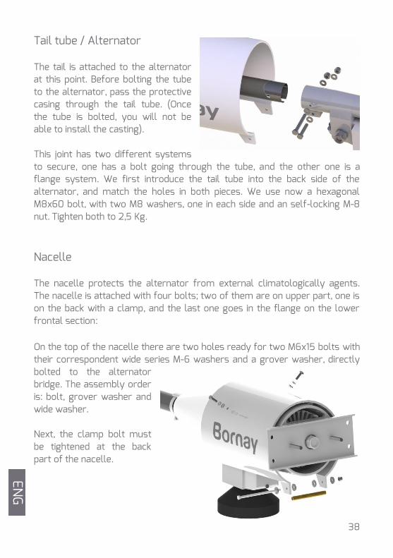
Tail tube / Alternator The tail is attached to the alternator at this point. Before bolting the tube to the alternator, pass the protective casing through the tail tube. (Once the tube is bolted, you will not be able to install the casting). This joint has two different systems to secure, one has a bolt going through the tube, and the other one is a flange system. We first introduce the tail tube into the back side of the alternator, and match the holes in both pieces. We use now a hexagonal M8x60 bolt, with two M8 washers, one in each side and an self-locking M-8 nut. Tighten both to 2,5 Kg.
Nacelle The nacelle protects the alternator from external climatologically agents. The nacelle is attached with four bolts; two of them are on upper part, one is on the back with a clamp, and the last one goes in the flange on the lower frontal section: On the top of the nacelle there are two holes ready for two M6x15 bolts with their correspondent wide series M-6 washers and a grover washer, directly bolted to the alternator bridge. The assembly order is: bolt, grover washer and wide washer. Next, the clamp bolt must be tightened at the back part of the nacelle.
ENG
39
Finally, on the lower front side, using the two flanges to anchor, we insert the brass tube (102 mm long x 10 mm exterior diameter), one M6x120 bolt, with an M6 wide series washer on each side, on the inner side of the nacelle between the two flange-forming flaps. Finally, secure using a washer and auto-blocking nut.
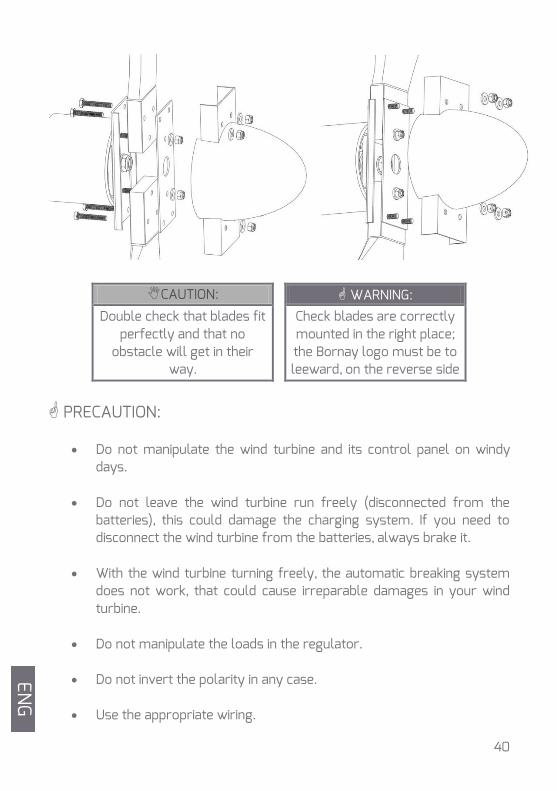
Blades and Frontal cone The blades, made reinforced carbon fiber/glass make direct contact with the wind. They are highly stressed. Their aerodynamics, specifically designed for Bornay wind turbines, makes the alternator turn faster or slower depending on wind speed. Blade assembly is carried out by securing them to the hub, with the relief logo towards the rear part, i.e. facing the alternator. The two external bolts will be M10x55, while the central internal bolt - now installed - is M10. Once installed, the blades must be adjusted. Without using any nuts or washers, the aluminum hub reinforcement layer is assembled, and this will give the assembled parts more solidity. To secure this reinforcement we use wide-series washers and normal M10 nuts into the two internal bolts. With the help of a dynamometric Allen key, these two nuts must be initially tightened to 2 kg. Once tightened, both nuts must then be retightened to 2.5 kg. The next step, having retightened both all nuts, is to insert the frontal nose cone into the four external bolts. Once installed, another wide-washer and M-10 self-blocking nut are applied. With the help of a dynamometric Allen key, these two nuts must be initially tightened to 2 kg. Once tightened, both nuts must then be retightened to 2.5 kg. Observe the next illustrations carefully. EN
G
40
CAUTION: WARNING: Double check that blades fit
perfectly and that no obstacle will get in their
way.
Check blades are correctly mounted in the right place; the Bornay logo must be to leeward, on the reverse side
PRECAUTION:
Do not manipulate the wind turbine and its control panel on windy days.
Do not leave the wind turbine run freely (disconnected from the batteries), this could damage the charging system. If you need to disconnect the wind turbine from the batteries, always brake it.
With the wind turbine turning freely, the automatic breaking system does not work, that could cause irreparable damages in your wind turbine.
Do not manipulate the loads in the regulator.
Do not invert the polarity in any case.
Use the appropriate wiring.
ES
P
ENG
41
Maintenance
After the installation One month after the installation of the wind turbine, we recommend checking that the bolts have the right torque and tightening, if necessary. Periodic maintenance To ensure long life for your wind turbine, we recommend the following maintenance schedule: Each 6 months If possible in the station changes, it is recommended to carry out a maintenance inspection in which the following points should be checked:
Checking and readjusting the torque required for every bolt. Checking state of wiring. Visual inspection of blades. Checking that the automatic breaking system works properly by
tilting it manually. The main wind turbine parts for maintenance inspections are:
Bearings Bornay wind turbines are equipped with great quality sealed bearings which require no maintenance. You can check to see if they turn freely or if the opposite occurs and some kind of friction or vibration is observed.
Bolts The bolts used in Bornay wind turbines are stainless steel. If a bolt is missing or in poor condition, it must be replaced right away in order to avoid any breaking or further damage. EN
G
42
Wiring All cable connections and switches must be properly checked in order to prevent any disconnection and to allow the wind turbine to run freely.
Blades The reinforced carbon fiber/glass blades are covered by a protective tape made of abrasive polyurethane on the leading edges of the blades.
After years of use, this tape may be affected by weather conditions. If the tape is missing or partially missing, contact your local installation office to have the tape replaced. By failing to replace the tape, the life of the blade will be seriously reduced due to the strong erosion the blade is exposed to.
Shock absorber The wind turbine has one hydraulic shock absorber installed that prevents abrupt shocks by promoting fast braking and slow return to its original position.
The shock absorber has a little slack at the beginning of its return movement, and this is normal. However, if this slack is observed to continue for over half the return movement, and if oil is leaking, the shock absorber must be replaced.
Lubrication Wind + wind turbines have three moving parts:
The front shaft (blades-alternator) is equipped with sealed bearings and covered with lubricant. It does not need any special attention; its lubricant will last during its lifetime.
The yawing shaft (wind turbine-tower) is equipped with sealed bearings and covered with lubricant. It does not need any special attention; Its lubricant will last during its lifetime.
The alternator shaft (alternator-yawing system) is a stainless steel tube covered with lubricant. It does not need any special attention. Its lubricant will last during its lifetime.
ENG
43
Frequently ask questions 1.- Can battery polarities be changed? No, this would cause the regulator to break down. 2.- ¿How can I find out what energy the wind turbine is providing? The energy can be known through the screen or with the specific software of Bornay. 3.- Could the drilled holes in the blades be bad? No, each wind turbine is assembled completely in production. If the drilled holes do not match up, try turning the blades round the other way. Some models have 3 and some have 5 holes drilled, and one of these is slightly off centre in order to define correct blade installation. 4.- Will one of these wind turbines provide enough power for a home? This kind of wind turbine is normally used together with other components to form a complete installation. These components are usually:
Solar panels: energy production. Solar regulators: to control battery charge from the solar panels. Batteries (accumulation of this energy): These installations are
normally designed to give three full days of independence, in other words they can supply the installation for three days without sun or wind. They use direct current.
Wind regulator: This is included with the wind turbine and this is what controls battery life. It ensures that battery voltage does not surpass dangerous levels. At the same time, it will brake the machinery when this does occur.
Inverter/Charger: This is the equipment that transforms direct current from batteries into alternating current for consumption (230V).
Back-up generator: In remote installations, this is installed to guarantee complete independent functioning of the installation. ENG
44
Normally, the inverter handles the start-up and stopping on the motor according to installation needs. For example, if the battery runs the inverter will order the motor to start.
5.- Can several wind turbines be set up in parallel? Yes, several wind turbines can be run in parallel. 6.- What kind of power is generated by the alternator? The wind turbine generates an alternating three-phase signal with a nominal voltage of approximately 230V. 7.- Should some protection be installed between the wind turbine and the regulator or between the regulator/interface and the battery? No, never. The regulator/interface is already carrying out these protective functions. If you were to install intermediate protection and this disconnected the electrical connection, the wind turbine would lose its charge and this could cause irreparable damage to the wind turbine or the regulator/interface. 8.- Should an auxiliary brake switch be installed? It is not necessary, but it may be advisable in the installations where you want to stop the wind turbine completely, in order to make some intervention in the equipment.
ENG
45
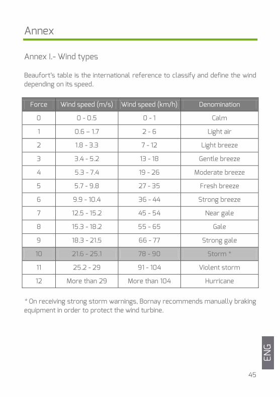
Annex Annex I.- Wind types Beaufort’s table is the international reference to classify and define the wind depending on its speed.
Force Wind speed (m/s) Wind speed (km/h) Denomination
0 0 - 0.5 0 - 1 Calm
1 0.6 – 1.7 2 - 6 Light air
2 1.8 - 3.3 7 - 12 Light breeze
3 3.4 - 5.2 13 - 18 Gentle breeze
4 5.3 - 7.4 19 - 26 Moderate breeze
5 5.7 - 9.8 27 - 35 Fresh breeze
6 9.9 - 10.4 36 - 44 Strong breeze
7 12.5 - 15.2 45 - 54 Near gale
8 15.3 - 18.2 55 - 65 Gale
9 18.3 - 21.5 66 - 77 Strong gale
10 21.6 - 25.1 78 - 90 Storm *
11 25.2 - 29 91 - 104 Violent storm
12 More than 29 More than 104 Hurricane
* On receiving strong storm warnings, Bornay recommends manually braking equipment in order to protect the wind turbine.
ENG
46
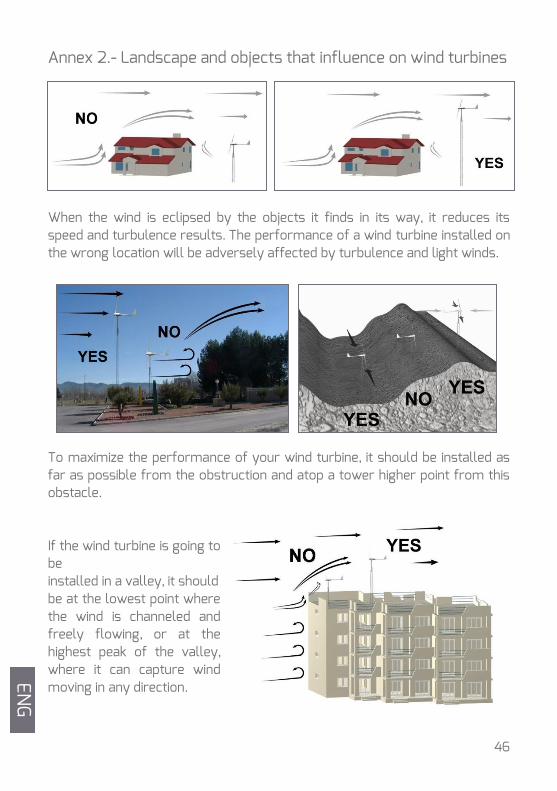
Annex 2.- Landscape and objects that influence on wind turbines
When the wind is eclipsed by the objects it finds in its way, it reduces its speed and turbulence results. The performance of a wind turbine installed on the wrong location will be adversely affected by turbulence and light winds.
To maximize the performance of your wind turbine, it should be installed as far as possible from the obstruction and atop a tower higher point from this obstacle. If the wind turbine is going to be installed in a valley, it should be at the lowest point where the wind is channeled and freely flowing, or at the highest peak of the valley, where it can capture wind moving in any direction.
ENG
48
Warranty
LIMITED WARRANTY Your new Wind + wind turbine is guaranteed against any material defect. This warranty does not include other equipment or accessories that could be involved in repairing the wind turbine. The warranty does not cover defects or damages produced by improper use or installation of the product. WARRANTY PERIOD – WIND + WIND TURBINES The warranty period for the Wind + wind turbines and their components is 36 months from date of original installation or 40 months from fabrication date. WIND + WIND TURBINES ACCESORIES The warranty period for the Bornay accessories is 36 months from date of original installation or 40 months from fabrication date. WARRANTY CONDITIONS The Warranty covers parts and labour in our workshops only. The wind turbine must be returned suitably packaged and at the buyer's expense. The Warranty does not cover breakage due to incorrect usage or equipment with signs of manipulation. Shipping is not covered by the Warranty. Bornay reserves the right to substitute or modify any part should the case call for such. Any wind turbine not meeting these conditions will be repaired and shipped at cost to buyer, with prior authorization from the customer.
ENG