Embed Size (px)
Citation preview
Wireless Environment
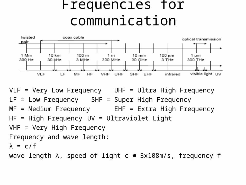
Frequencies for communication
VLF = Very Low Frequency UHF = Ultra High Frequency
LF = Low Frequency SHF = Super High Frequency
MF = Medium Frequency EHF = Extra High Frequency
HF = High Frequency UV = Ultraviolet Light
VHF = Very High Frequency
Frequency and wave length:
λ = c/f
wave length λ, speed of light c 3x10⁸m/s, frequency f≅
Frequencies for mobile communication
• VHF-/UHF-ranges for mobile radio simple, small antenna for cars deterministic propagation characteristics, reliable connections
• SHF and higher for directed radio links, satellite communication small antenna, focusing large bandwidth available
• Wireless LANs use frequencies in UHF to SHF spectrum some systems planned up to EHF limitations due to absorption by water and oxygen molecules (resonance frequencies)
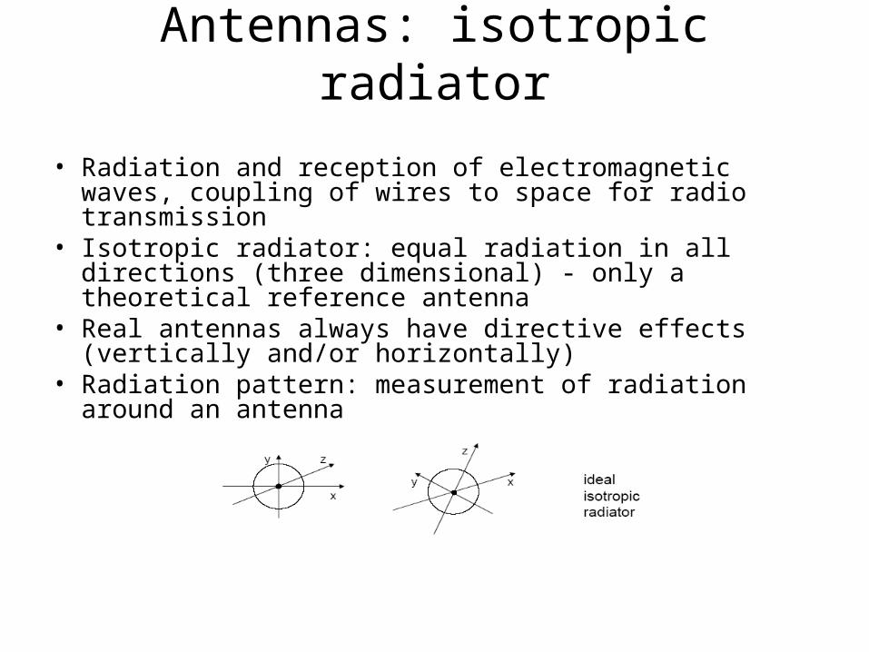
Antennas: isotropic radiator
• Radiation and reception of electromagnetic waves, coupling of wires to space for radio transmission
• Isotropic radiator: equal radiation in all directions (three dimensional) - only a theoretical reference antenna
• Real antennas always have directive effects (vertically and/or horizontally)
• Radiation pattern: measurement of radiation around an antenna
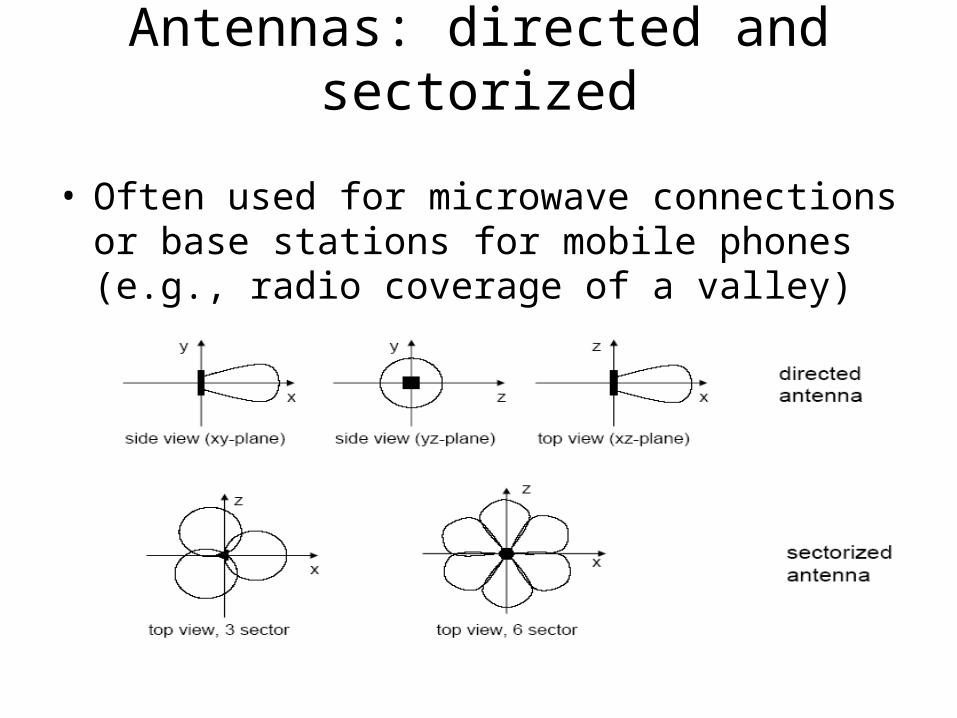
Antennas: directed and sectorized
• Often used for microwave connections or base stations for mobile phones (e.g., radio coverage of a valley)
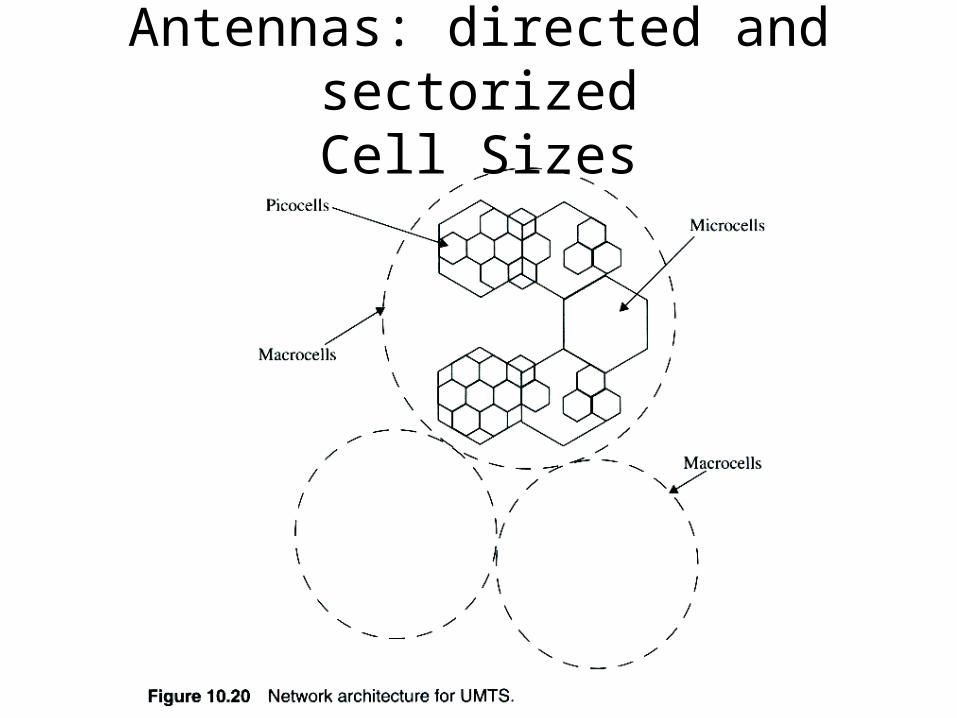
Antennas: directed and sectorizedCell Sizes
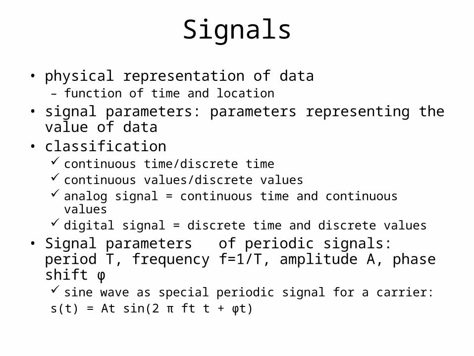
Signals
• physical representation of data– function of time and location
• signal parameters: parameters representing the value of data
• classification continuous time/discrete time continuous values/discrete values analog signal = continuous time and continuous values digital signal = discrete time and discrete values
• Signal parameters of periodic signals: period T, frequency f=1/T, amplitude A, phase shift ϕ sine wave as special periodic signal for a carrier:s(t) = At sin(2 π ft t + ϕt)
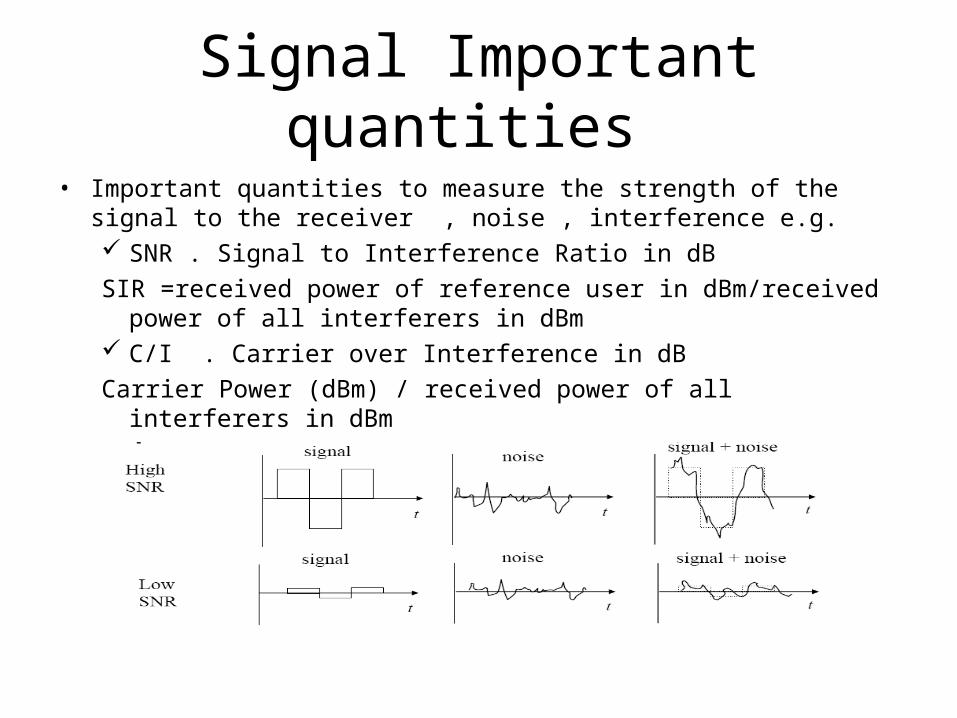
Signal Important quantities
• Important quantities to measure the strength of the signal to the receiver , noise , interference e.g. SNR . Signal to Interference Ratio in dB
SIR =received power of reference user in dBm/received power of all interferers in dBm
C/I . Carrier over Interference in dB
Carrier Power (dBm) / received power of all interferers in dBm
Signal Important quantities
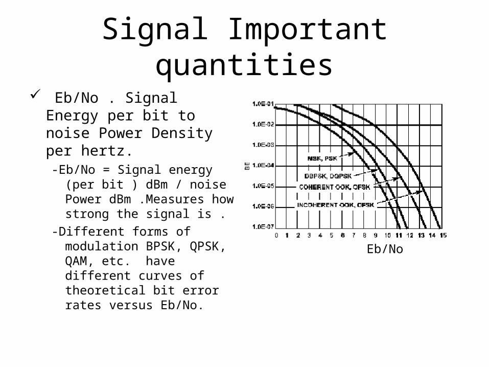
Eb/No . Signal Energy per bit to noise Power Density per hertz.-Eb/No = Signal energy (per
bit ) dBm / noise Power dBm .Measures how strong the signal is .
-Different forms of modulation BPSK, QPSK, QAM, etc. have different curves of theoretical bit error rates versus Eb/No.
Eb/No
Signal propagation ranges
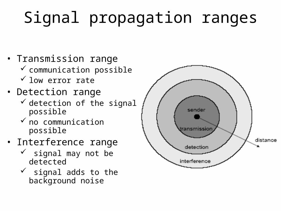
• Transmission range communication possible low error rate
• Detection range detection of the signal possible no communication possible
• Interference range signal may not be detected signal adds to the background
noise
Signal propagation
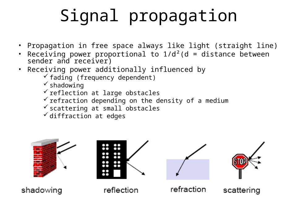
• Propagation in free space always like light (straight line)• Receiving power proportional to 1/d²(d = distance between sender and
receiver)• Receiving power additionally influenced by
fading (frequency dependent) shadowing reflection at large obstacles refraction depending on the density of a medium scattering at small obstacles diffraction at edges
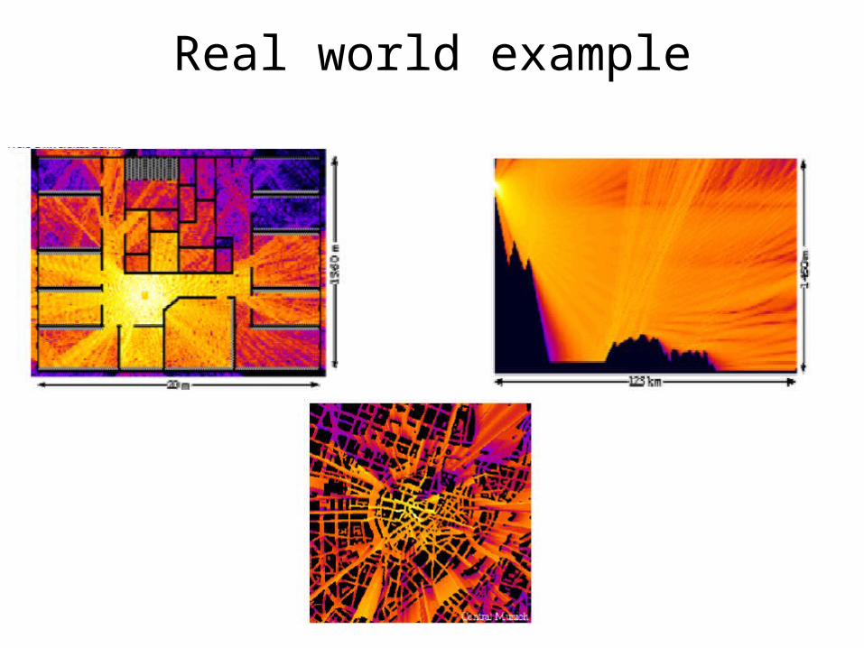
Real world example
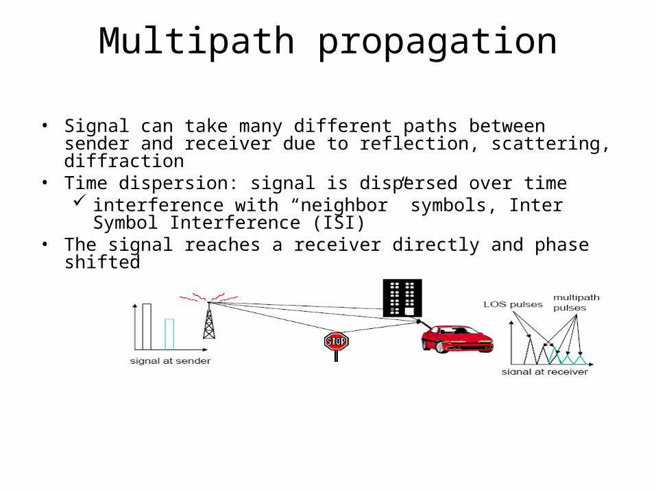
Multipath propagation
• Signal can take many different paths between sender and receiver due to reflection, scattering, diffraction
• Time dispersion: signal is dispersed over time interference with “neighbor” symbols, Inter Symbol Interference
(ISI)• The signal reaches a receiver directly and phase shifted
distorted signal depending on the phases of the different parts
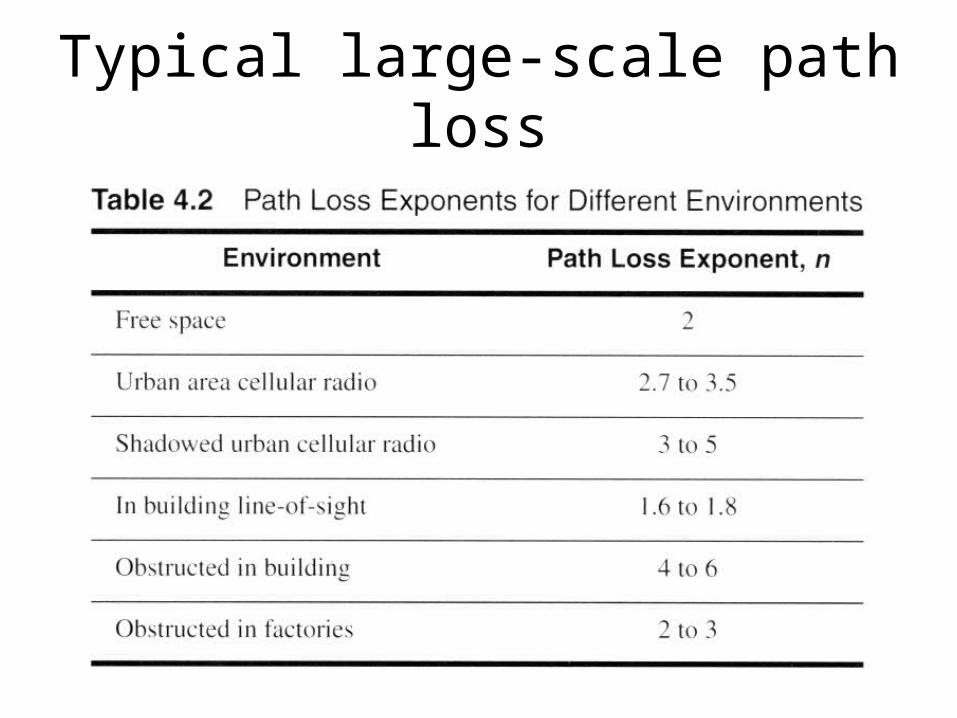
Typical large-scale path loss
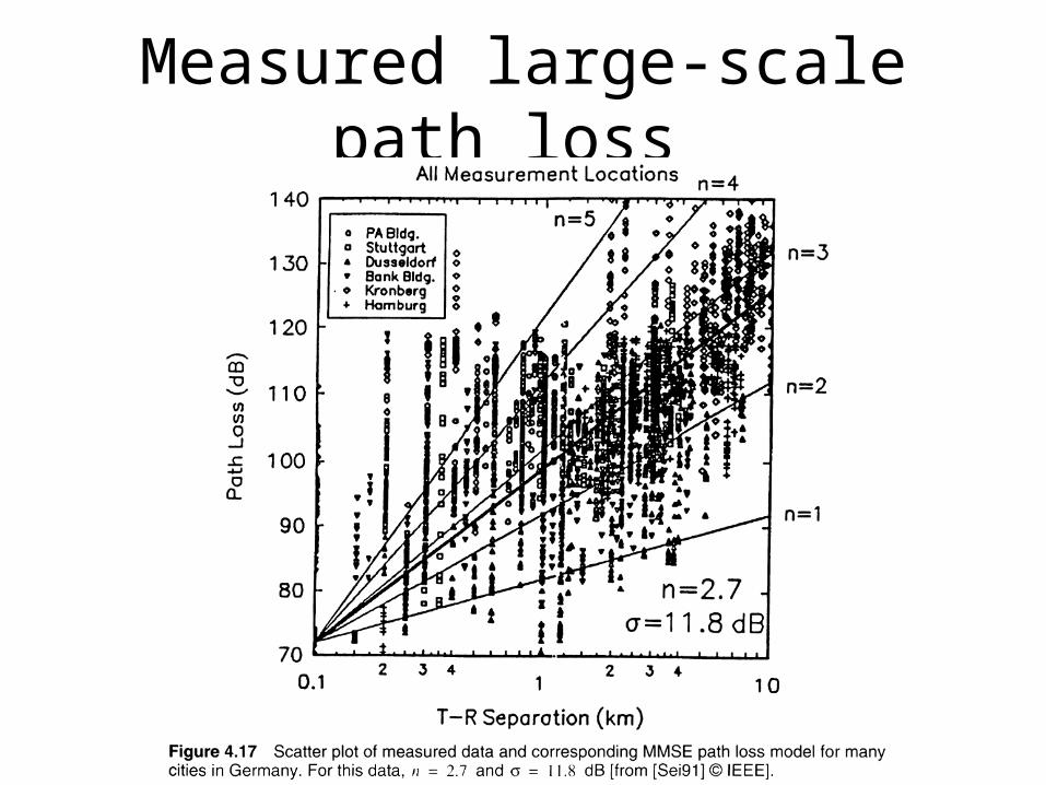
Measured large-scale path loss
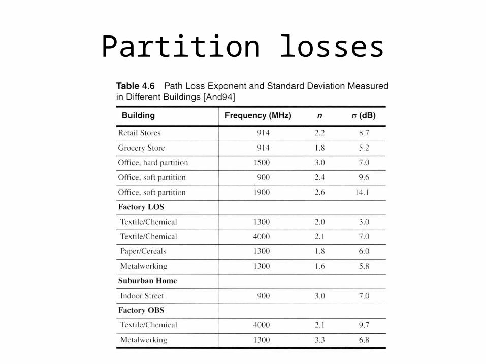
Partition losses
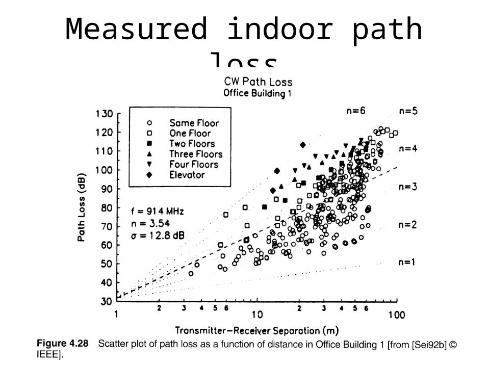
Measured indoor path loss
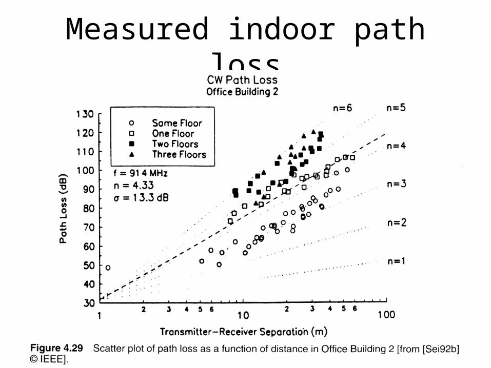
Measured indoor path loss
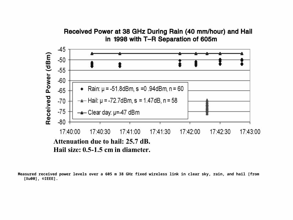
Measured received power levels over a 605 m 38 GHz fixed wireless link in clear sky, rain, and hail [from [Xu00], ©IEEE].
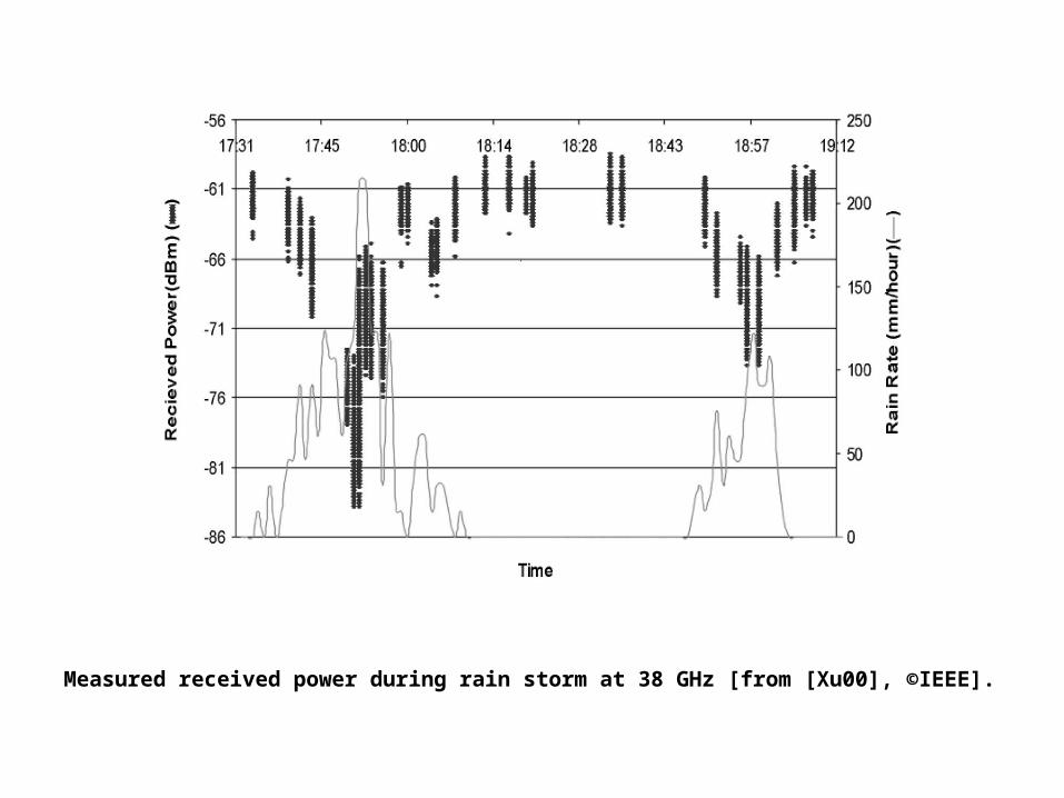
Measured received power during rain storm at 38 GHz [from [Xu00], ©IEEE].
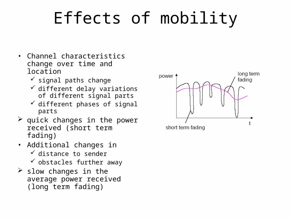
Effects of mobility
• Channel characteristics change over time and location signal paths change different delay variations of
different signal parts different phases of signal parts
quick changes in the power received (short term fading)
• Additional changes in distance to sender obstacles further away
slow changes in the average power received (long term fading)
Multiple Access protocols• single shared broadcast channel • two or more simultaneous transmissions by nodes:
interference – only one node can send successfully at a time
multiple access protocol• distributed algorithm that determines how nodes share
channel, i.e., determine when node can transmit• communication about channel sharing must use
channel itself! • what to look for in multiple access protocols:
Ideal Multiple Access Protocol
Broadcast channel of rate R bps
1. When one node wants to transmit, it can send at rate R.
2. When M nodes want to transmit, each can send at average rate R/M
3. Fully decentralized:– no special node to coordinate transmissions– no synchronization of clocks, slots
4. Simple
MAC Protocols: a taxonomy
Three broad classes:• Channel Partitioning
– divide channel into smaller “pieces” (time slots, frequency, code)
– allocate piece to node for exclusive use
• Random Access– channel not divided, allow collisions– “recover” from collisions
• “Taking turns”– tightly coordinate shared access to avoid collisions
Multiplexing
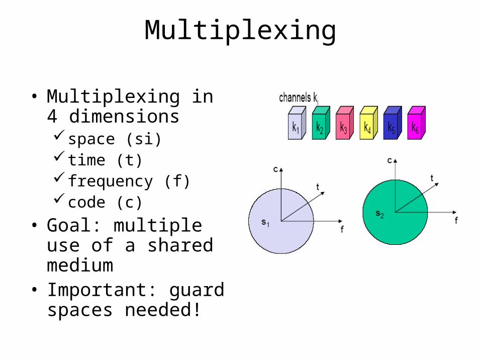
• Multiplexing in 4 dimensionsspace (si) time (t) frequency (f)code (c)
• Goal: multiple use of a shared medium
• Important: guard spaces needed!
Time multiplex
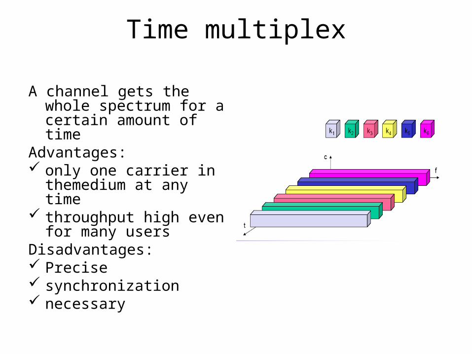
A channel gets the whole spectrum for a certain amount of time
Advantages: only one carrier in
themedium at any time throughput high even for
many usersDisadvantages: Precise synchronization necessary
Channel Partitioning MAC protocols: TDMA
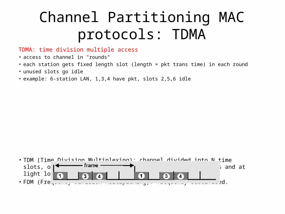
TDMA: time division multiple access • access to channel in "rounds" • each station gets fixed length slot (length = pkt trans time) in each round • unused slots go idle • example: 6-station LAN, 1,3,4 have pkt, slots 2,5,6 idle
• TDM (Time Division Multiplexing): channel divided into N time slots, one per user; inefficient with low duty cycle users and at light load.
• FDM (Frequency Division Multiplexing): frequency subdivided.
Frequency multiplex
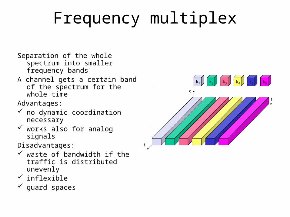
Separation of the whole spectrum into smaller frequency bands
A channel gets a certain band of the spectrum for the whole time
Advantages: no dynamic coordination
necessary works also for analog signals Disadvantages: waste of bandwidth if the traffic
is distributed unevenly inflexible guard spaces
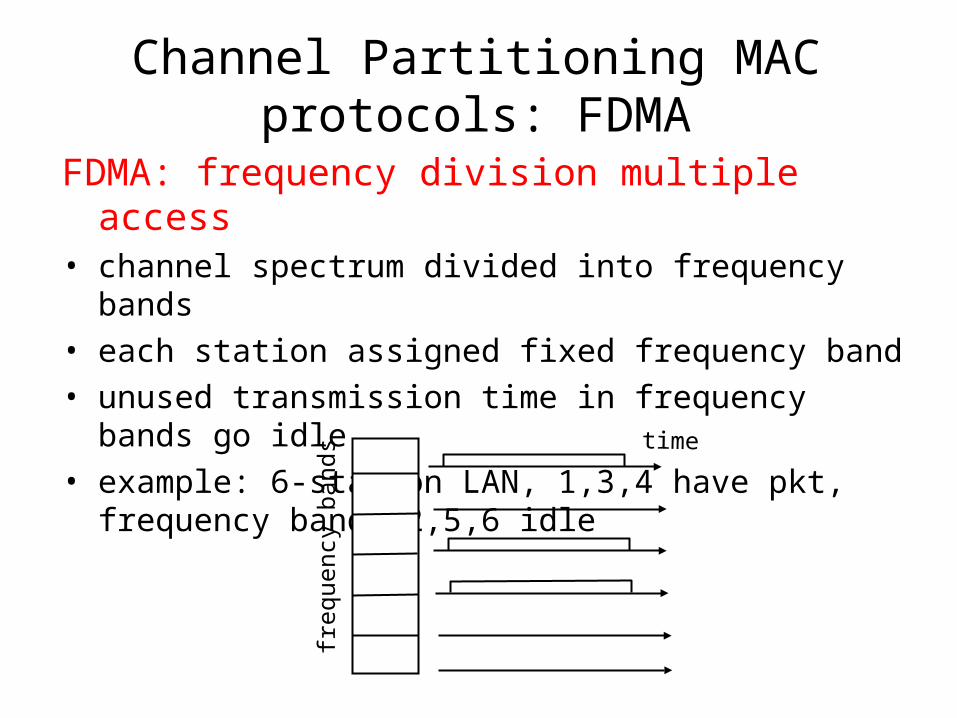
Channel Partitioning MAC protocols: FDMA
FDMA: frequency division multiple access • channel spectrum divided into frequency bands• each station assigned fixed frequency band• unused transmission time in frequency bands go idle • example: 6-station LAN, 1,3,4 have pkt, frequency bands
2,5,6 idle
frequ
ency
bands time
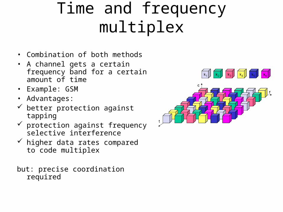
Time and frequency multiplex
• Combination of both methods• A channel gets a certain
frequency band for a certain amount of time
• Example: GSM• Advantages: better protection against tapping protection against frequency
selective interference higher data rates compared to
code multiplex
but: precise coordination required
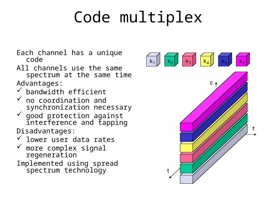
Code multiplex
Each channel has a unique codeAll channels use the same
spectrum at the same timeAdvantages: bandwidth efficient no coordination and
synchronization necessary good protection against
interference and tappingDisadvantages: lower user data rates more complex signal
regenerationImplemented using spread
spectrum technology
Channel Partitioning (CDMA)
CDMA (Code Division Multiple Access) • unique “code” assigned to each user; i.e., code set partitioning• used mostly in wireless broadcast channels (cellular, satellite,
etc)• all users share same frequency, but each user has own
“chipping” sequence (i.e., code) to encode data• encoded signal = (original data) X (chipping sequence)• decoding: inner-product of encoded signal and chipping
sequence• allows multiple users to “coexist” and transmit simultaneously
with minimal interference (if codes are “orthogonal”)
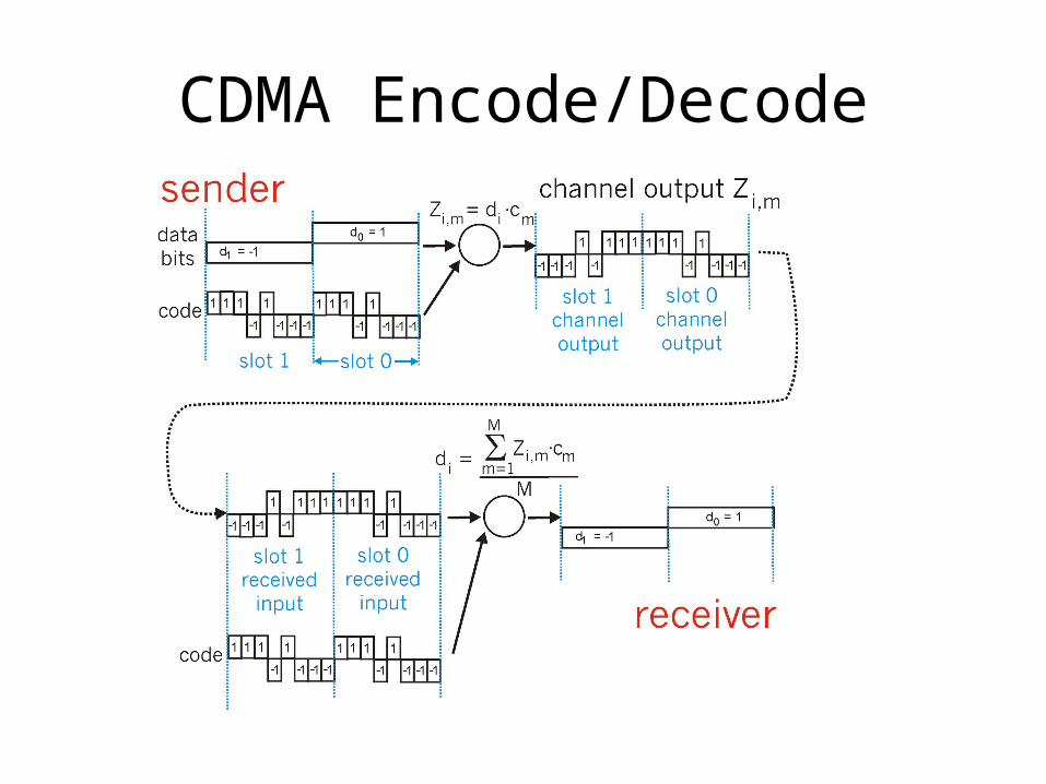
CDMA Encode/Decode
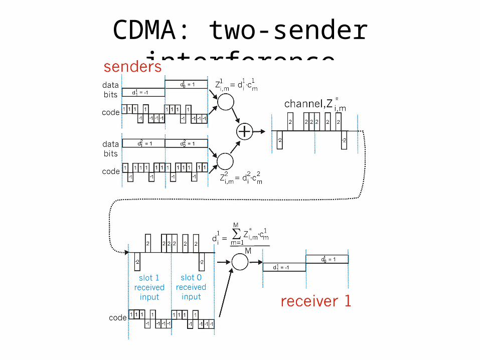
CDMA: two-sender interference
space division multiplex
• Cell structure– Implements space division multiplex: base station covers a
certain transmission area (cell)– Mobile stations communicate only via the base station– Advantages of cell structures:
higher capacity, higher number of users less transmission power needed more robust, decentralized base station deals with interference, transmission area etc. locally
– Problems: fixed network needed for the base stations handover (changing from one cell to another) necessary interference with other cells
– Cell sizes from some 100 m in cities to, e.g., 35 km on the country side (GSM) - even less for higher frequencies
Medium access control
• Motivation for a specialized MAC in wireless
– Consider carrier sense –CS- multiple access with collision detection-CD- (CSMA/CD) – wired nets:A sender senses the medium to see if it is free. If the medium is busy, the sender waits until it is free. If the medium is free, the sender starts transmitting
data and continues to listen the medium. If the sender detects a collision while sending, it stops
at once.
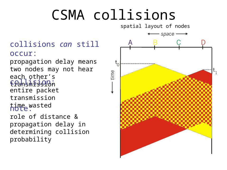
CSMA collisions
collisions can still occur:propagation delay means two nodes may not heareach other’s transmissioncollision:entire packet transmission time wasted
spatial layout of nodes
note:role of distance & propagation delay in determining collision probability
CSMA/CD (Collision Detection)CSMA/CD: carrier sensing, deferral as in CSMA
– collisions detected within short time– colliding transmissions aborted, reducing channel
wastage
• collision detection: – easy in wired LANs: measure signal strengths,
compare transmitted, received signals– difficult in wireless LANs: receiver shut off while
transmitting
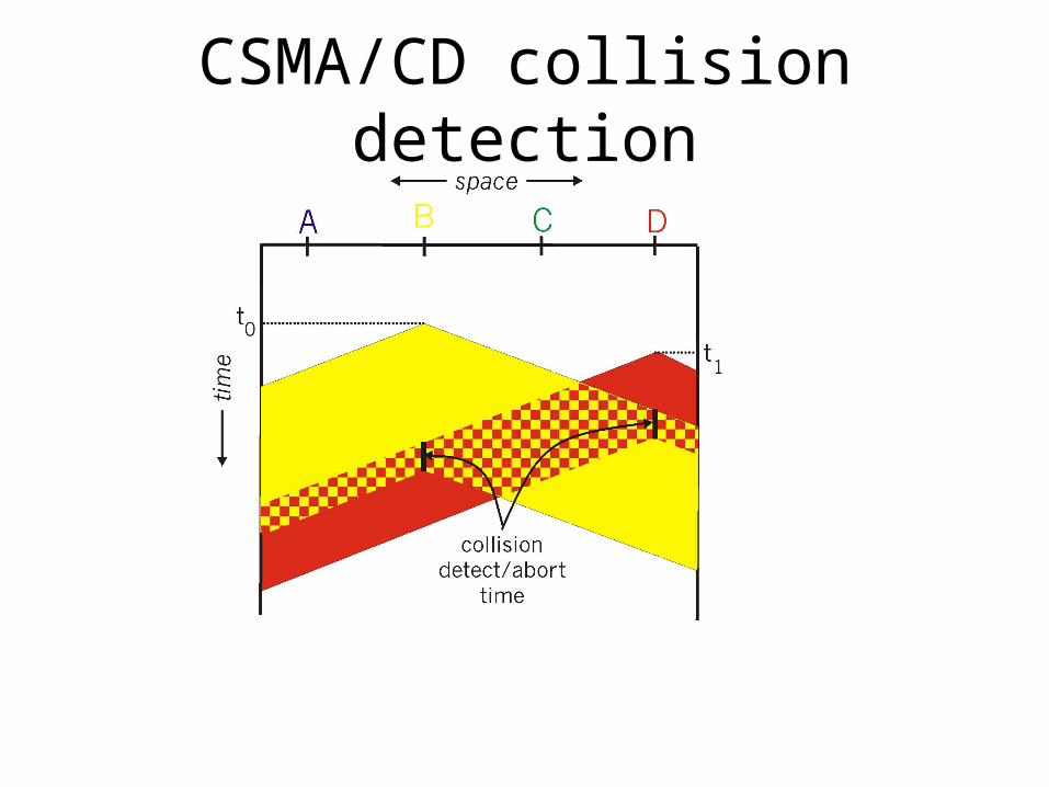
CSMA/CD collision detection
Ethernet uses CSMA/CD
• No slots• adapter doesn’t transmit if
it senses that some other adapter is transmitting, that is, carrier sense
• transmitting adapter aborts when it senses that another adapter is transmitting, that is, collision detection
• Before attempting a retransmission, adapter waits a random time, that is, random access
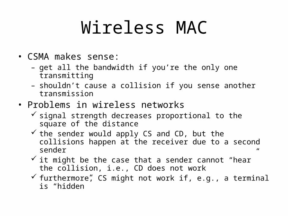
• CSMA makes sense:– get all the bandwidth if you’re the only one transmitting– shouldn’t cause a collision if you sense another transmission
• Problems in wireless networks signal strength decreases proportional to the square of the
distance the sender would apply CS and CD, but the collisions happen at
the receiver due to a second sender it might be the case that a sender cannot “hear” the collision, i.e.,
CD does not work furthermore, CS might not work if, e.g., a terminal is “hidden”
Wireless MAC
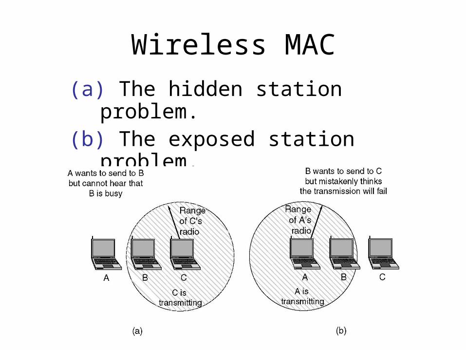
(a) The hidden station problem.(b) The exposed station problem.
Wireless MAC
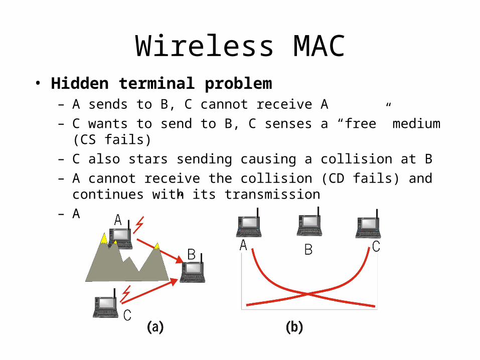
• Hidden terminal problem– A sends to B, C cannot receive A– C wants to send to B, C senses a “free” medium (CS fails)– C also stars sending causing a collision at B– A cannot receive the collision (CD fails) and continues with its
transmission– A is “hidden” for C
Wireless MAC
Medium access control
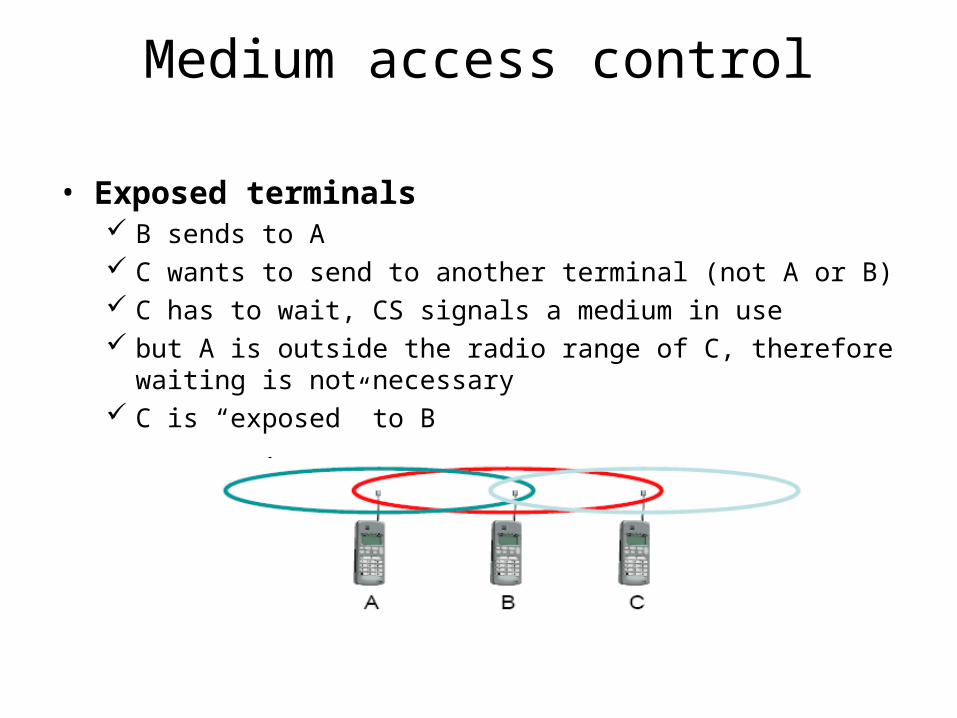
• Exposed terminals B sends to A C wants to send to another terminal (not A or B) C has to wait, CS signals a medium in use but A is outside the radio range of C, therefore waiting is not
necessary C is “exposed” to B
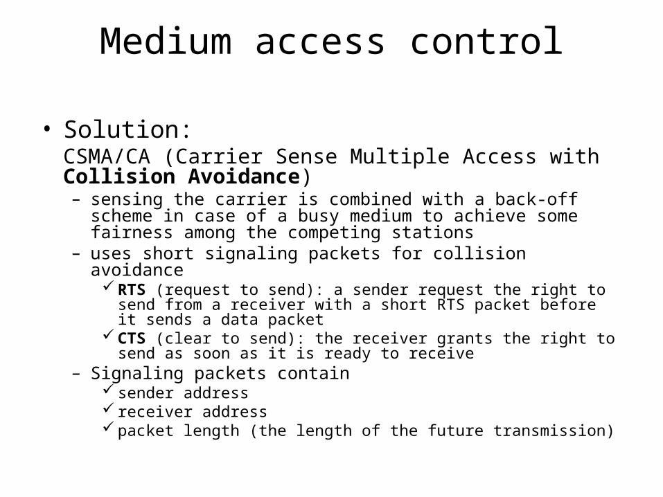
Medium access control
• Solution:CSMA/CA (Carrier Sense Multiple Access with Collision Avoidance) – sensing the carrier is combined with a back-off scheme in case
of a busy medium to achieve some fairness among the competing stations
– uses short signaling packets for collision avoidance RTS (request to send): a sender request the right to send from a
receiver with a short RTS packet before it sends a data packet CTS (clear to send): the receiver grants the right to send as soon as
it is ready to receive– Signaling packets contain
sender address receiver address packet length (the length of the future transmission)
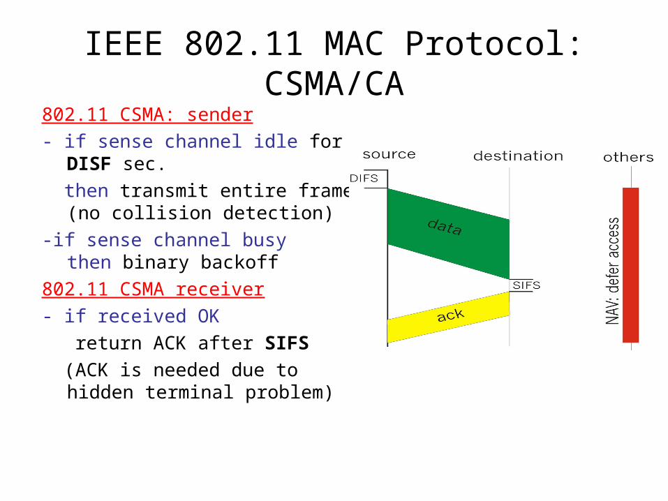
IEEE 802.11 MAC Protocol: CSMA/CA802.11 CSMA: sender
- if sense channel idle for DISF sec.
then transmit entire frame (no collision detection)
-if sense channel busy then binary backoff
802.11 CSMA receiver
- if received OK
return ACK after SIFS
(ACK is needed due to hidden terminal problem)
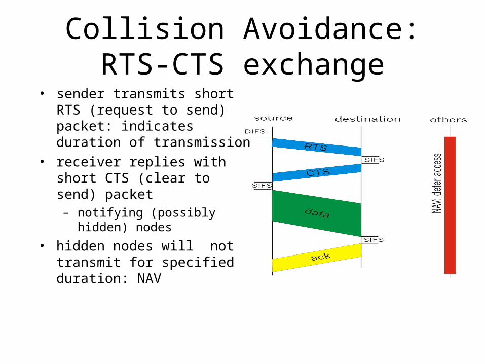
Collision Avoidance: RTS-CTS exchange
• sender transmits short RTS (request to send) packet: indicates duration of transmission
• receiver replies with short CTS (clear to send) packet– notifying (possibly hidden)
nodes
• hidden nodes will not transmit for specified duration: NAV
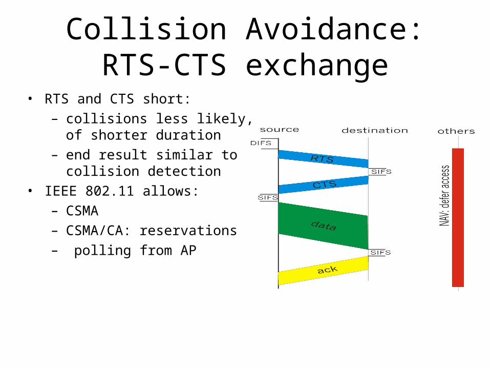
Collision Avoidance: RTS-CTS exchange
• RTS and CTS short:– collisions less likely, of shorter
duration– end result similar to collision
detection• IEEE 802.11 allows:
– CSMA– CSMA/CA: reservations– polling from AP
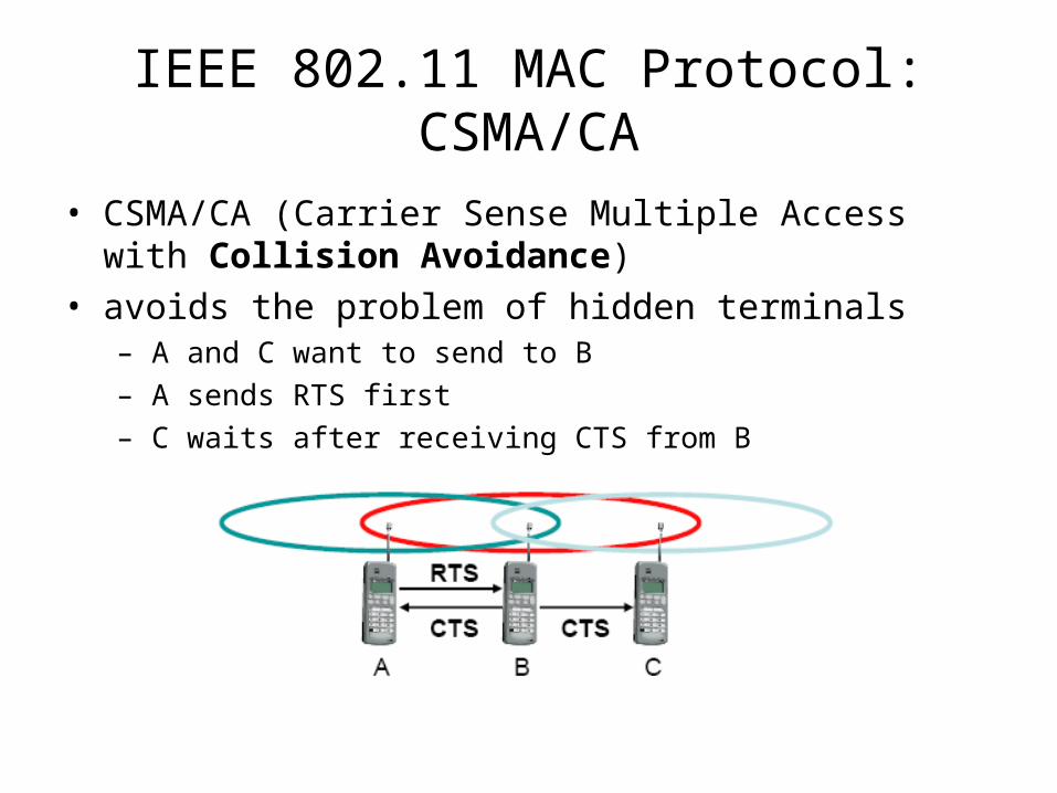
• CSMA/CA (Carrier Sense Multiple Access with Collision Avoidance)
• avoids the problem of hidden terminals– A and C want to send to B
– A sends RTS first
– C waits after receiving CTS from B
IEEE 802.11 MAC Protocol: CSMA/CA
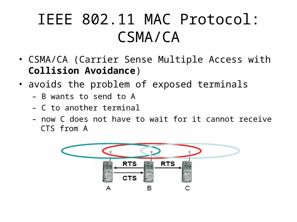
• CSMA/CA (Carrier Sense Multiple Access with Collision Avoidance)
• avoids the problem of exposed terminals– B wants to send to A
– C to another terminal
– now C does not have to wait for it cannot receive CTS from A
IEEE 802.11 MAC Protocol: CSMA/CA
Modulation
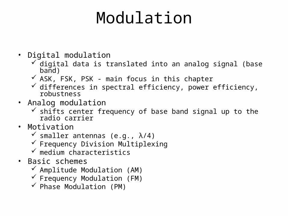
• Digital modulation digital data is translated into an analog signal (base band) ASK, FSK, PSK - main focus in this chapter differences in spectral efficiency, power efficiency, robustness
• Analog modulation shifts center frequency of base band signal up to the radio carrier
• Motivation smaller antennas (e.g., λ/4) Frequency Division Multiplexing medium characteristics
• Basic schemes Amplitude Modulation (AM) Frequency Modulation (FM) Phase Modulation (PM)
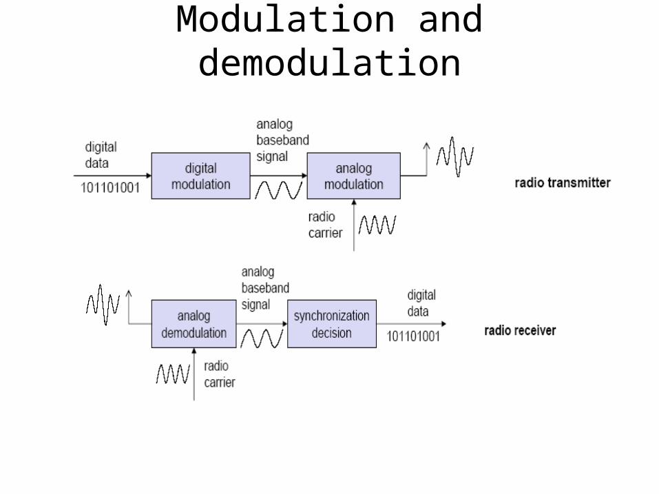
Modulation and demodulation
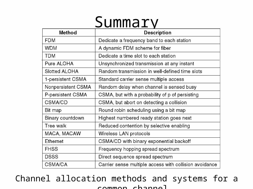
Summary
Channel allocation methods and systems for a common channel.
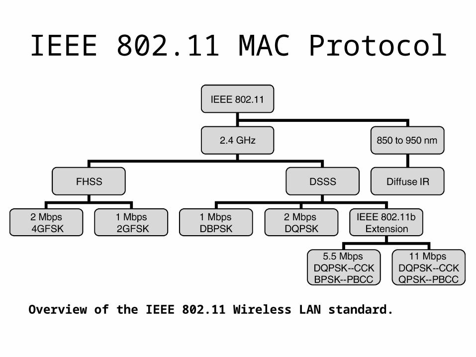
Overview of the IEEE 802.11 Wireless LAN standard.
IEEE 802.11 MAC Protocol
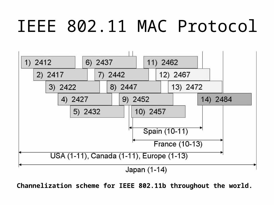
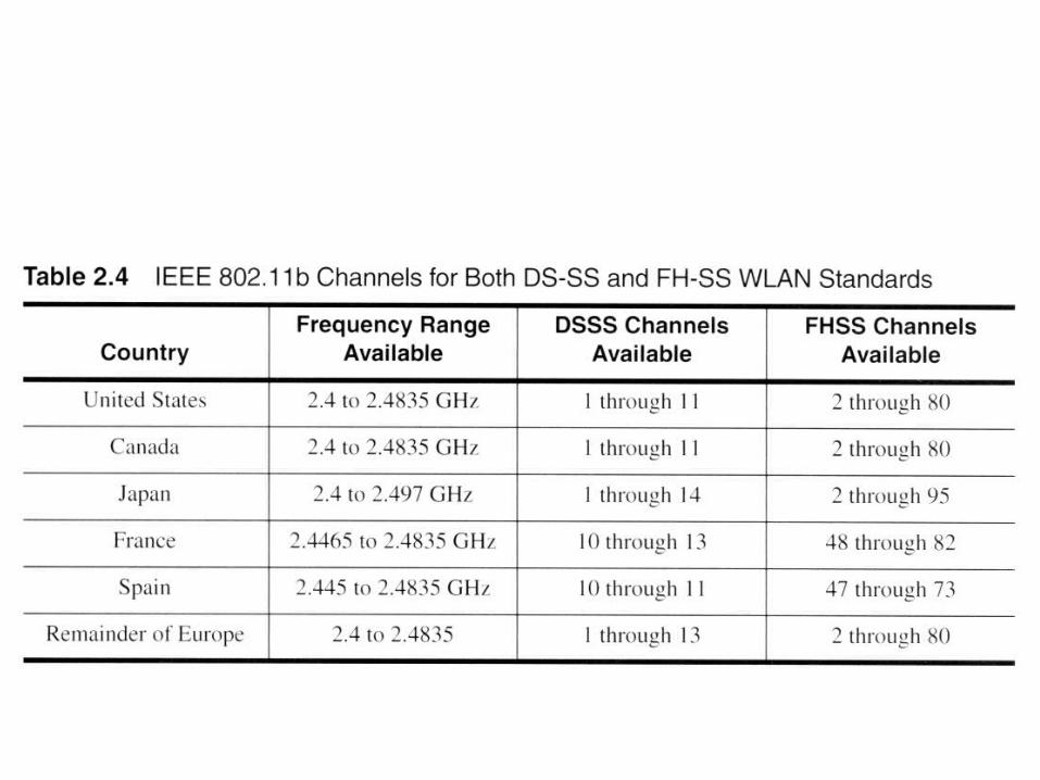
Channelization scheme for IEEE 802.11b throughout the world.
IEEE 802.11 MAC Protocol