Embed Size (px)
Citation preview

WORKING NCITS XXXDRAFT T10/1363-D
Revision � 10gNovember 12, 2001
INFORMATION TECHNOLOGY -SCSI Multimedia Commands – 3 (MMC-3)This is a draft proposal of the National Committee for Information Technology Standards (NCITS). NCITS isaccredited by, and approved under rules approved by, the American National Standards Institute (ANSI). Assuch this is not a completed standard. The NCITS T10 Technical Committee may modify this document as aresult of comments received during public review and its approval as a standard. Use of the informationcontained herein is at your own risk.Permission is granted to members of NCITS, its technical committees, and their associated task groups toreproduce this document for the purposes of NCITS standards activities without further permission, providedthis notice is included. All other rights are reserved. Any commercial or for-profit replication or republicationis prohibited.
MMC-3 Technical Editor:Bill McFerrin, CD Edge, Inc.P. O. Box 429Windsor, CO 80550Tel. (720) 320-0790E-mail: [email protected]
Reference numberISO/IEC ***** :XXXX
ANSI NCITS .***** :XXXXPrinted: ******, XXXX

MMC-3 Revision 10g
ii
POINTS OF CONTACTNCITS T10 Chair NCITS T10 Vice-ChairJohn B. Lohmeyer George O. PenokieLSI Logic Corp. Tivoli Systems Inc.4420 ArrowsWest Dr. MS: 2C6Colo. Springs, CO 80907-3444 3605 Highway 52 N.Tel: (719) 533-7560 Rochester, MN 55901 USAFax: (719) 533-7183 Telephone: (507) 253-5208Email: [email protected] Facsimile: (507) 253-2880
Email: [email protected] SecretariatNCITS Secretariat Telephone: 202-737-88881250 Eye Street, NW Suite 200 Facsimile: 202-638-4922Washington, DC 20005 e-mail: [email protected] ReflectorInternet address for subscription to the T10 reflector: [email protected] address for distribution via T10 reflector: [email protected] ReflectorInternet address for subscription to the MMC Reflector [email protected] address for distribution via MMC Reflector [email protected] DistributionGlobal Engineering Telephone: 303-792-2181 or15 Inverness Way East 800-854-7179Englewood, CO 80112-5704 Facsimile: 303-792-2192

MMC-3 Draft Revision 10g
iii
REVISION HISTORYDraft Revision 0.0A Initial draft of the documentDraft Revision 1.0 Includes all known changes from MT Fuji4 and comments from PioneerDraft Revision 2.0 Includes Sony Double Density CD proposalDraft Revision 3.0 Includes September Mt Fuji4 changesDraft Revision 4.0 Includes October Mt Fuji5 changesDraft Revision 5.0 Includes November Mt Fuji5 changesDraft Revision 6.0 Includes December editors meeting changes from Sony and PioneerDraft Revision 7.0 Includes MRW addition, changes associated with "zero loss linking" on CDDraft Revision 8.0 Corrections, DVD+RW changesDraft Revision 9.0 March 2001 MMC WG review corrections & changesDraft Revision 10A May 3, 2001: Changes resulting from T10 ballot comments from:
R. Weber, ENDLP. Aloisi, Texas InstrumentsP. Johanssen, Congruent SoftwareTasuku Kasebayashi, ToshibaM. Kohda, Pioneer (not with vote)
Draft Revision 10B July 6, 2001: Changes resulting from T10 ballot comments from:R. Weber, ENDLR. Elliot, CompaqD. Erickson, Dell (not with vote)W. McFerrin, Philips (not with vote)H. Gabryjelski, Microsoft (not with vote)M. Takahashi, Ricoh (not with vote)
Draft Revision 10C July 18, 2001: Changes from T10 ballot comments from:R. Elliot, Compaq
Draft Revision 10D August 28,2001: Action on additional comments fromR. Elliot, Compaq and R. Weber, ENDL Texas
Draft Revision 10E September 19, 2001:Additional description as requested by Katata, Pioneer;
Draft Revision 10F Reference error discovered by Jim Turner, Sonic SolutionsMissing references, Takahashi, RicohConfusing table captions, McFerrin, PhilipsAdditional description of CD-MRW, McFerrin, Philips
Draft Revision 10G Reference errors in Annex K wrt TOC forms, Shigeyoshi Hashi, NECCD-MRW recommendations for GAA content, Andre Hedrick, Linux ATADevelopment

MMC-3 Revision 10g
iv
THIS PAGEIS
INTENTIONALLY BLANK

MMC-3 Draft Revision 10g
v
BSR®
NCITS XXX
for Information Technology –
SCSI Multimedia Commands – 3 (MMC-3)
SecretariatInformation Technology Industry Council
AbstractThis standard defines the SCSI command set extensions to access multimedia features for allclasses of SCSI devices. The applicable clauses of this standard when used in conjunction with theSCSI Primary Commands specification, SCSI Block Commands, and other applicable command setdocuments pertaining to the subject device class, define the full standard set of commands availablefor that device in the SCSI environment.

MMC-3 Revision 10g
vi
AmericanNationalStandard
Approval of an American National Standard requires verification byANSI that the requirements for due process, consensus and othercriteria for approval have been met by the standards developer.Consensus is established when, in the judgment of the ANSI Board ofStandards Review, directly and materially affected interests havereached substantial agreement. Substantial agreement means muchmore than a simple majority, but not necessarily unanimity. Consensusrequires that all views and objections be considered and that effort bemade towards their resolution.The use of American National Standards is completely voluntary; theirexistence does not in any respect preclude anyone, whether he hasapproved the standards or not, from manufacturing, marketing,purchasing, or using products, processes, or procedures not conformingto the standards.The American National Standards Institute does not develop standardsand in no circumstances give interpretation on any American NationalStandard. Moreover, no person shall have the right or authority to issuean interpretation of an American National Standard in the name of theAmerican National Standards Institute. Requests for interpretationsshould be addressed to the secretariat or sponsor whose name appearson the title page of this standard.
CAUTION NOTICE: This American National Standard may berevised or withdrawn at any time. The procedures of the AmericanNational Standards Institute require that action be taken periodically toreaffirm, revise, or withdraw this standard. Purchasers of AmericanNational Standards may receive current information on all standards bycalling or writing the American National Standards Institute.
CAUTION NOTICE: The developers of this standard have requested that holder�s of patents that maybe required for the implementation of this standard, disclose such patents to the publisher. However,neither the developers nor the publisher has undertaken a patent search in order to identify which, if any,patents may apply to this standard. As of the date of publication of this standard and following calls for theidentification of patents that may be required for the implementation of the standard, no such claims havebeen made. The developer or publisher in respect to any standard it processes conducts no further patentsearch. No representation is made or implied that licenses are not required to avoid infringement in theuse of this standard.
Published byAmerican National Standards Institute1430 Broadway, New York, NY 10018Copyright © 1998 by American National Standards InstituteAll rights reserved.
No part of this publication may be reproduced in anyform, in an electronic retrieval system or otherwise,without prior written permission ITI, 1250 Eye Street NW,Washington, DC 20005Printed in the United States of America

MMC-3 Draft Revision 10g
2
ContentsForward ....................................................................................................................................................... 301 Scope..................................................................................................................................................... 12 References............................................................................................................................................. 2
2.1 Normative References .................................................................................................................... 22.1.1 Approved references ............................................................................................................... 22.1.2 References under development .............................................................................................. 2
2.2 Other references............................................................................................................................. 33 Terms and Definitions ............................................................................................................................ 4
3.1 Definitions ....................................................................................................................................... 43.2 List of Acronyms ........................................................................................................................... 133.3 Keywords ...................................................................................................................................... 143.4 Conventions.................................................................................................................................. 15
4 Multi-Media Device Models.................................................................................................................. 164.1 General ......................................................................................................................................... 16
4.1.1 Logical Blocks ....................................................................................................................... 164.1.2 Data cache ............................................................................................................................ 164.1.3 Resets ................................................................................................................................... 17
4.1.3.1 Power-On Reset ................................................................................................................ 174.1.3.2 Hard Reset......................................................................................................................... 174.1.3.3 Device Reset...................................................................................................................... 17
4.1.4 Error reporting ....................................................................................................................... 184.1.5 Deferred Errors...................................................................................................................... 184.1.6 Removable medium .............................................................................................................. 19
4.2 CD Device Model.......................................................................................................................... 204.2.1 Recorded CD Media Structure .............................................................................................. 20
4.2.1.1 The CD Frame Structure ................................................................................................... 204.2.1.2 Sub-channel....................................................................................................................... 21
4.2.2 Physical Track Topology: Single Session Disc ..................................................................... 234.2.3 Physical track topology - Multi-Session Disc......................................................................... 23
4.2.3.1 Tracks ................................................................................................................................ 234.2.3.2 Frame Addressing.............................................................................................................. 244.2.3.3 Q Sub-channel ................................................................................................................... 244.2.3.4 Q Sub-channel in the Program Area.................................................................................. 25
4.2.3.4.1 ADR=1 (0001b) � Mode-1 Q........................................................................................ 254.2.3.4.2 ADR=2 (0010b) � Mode-2 Q........................................................................................ 254.2.3.4.3 ADR=3 (0011b) � Mode-3 Q........................................................................................ 26
4.2.3.5 Q Sub-channel in the Lead-out Area ................................................................................. 274.2.3.6 Q Sub-channel in the Lead-in Area ................................................................................... 27
MMC-3 Draft Revision 10g
3
4.2.3.6.1 Mode-1 Q ..................................................................................................................... 274.2.3.6.2 Mode-2 Q ..................................................................................................................... 284.2.3.6.3 Mode-5 Q ..................................................................................................................... 28
4.2.3.7 CD Main Channel Block Formats ...................................................................................... 291.1.1.1.1 Block Format for Audio................................................................................................. 304.2.3.7.1 Block Format for Mode 0 Data ..................................................................................... 304.2.3.7.2 Block Format for Mode 1 Data ..................................................................................... 304.2.3.7.3 Block Format for Mode 2 Data ..................................................................................... 31
4.2.3.7.3.1 Block Format for Mode 2 formless Data ................................................................ 314.2.3.7.3.2 Block Format for Mode 2 form 1 Data ................................................................... 314.2.3.7.3.3 Block Format for Mode 2 form 2 Data ................................................................... 32
4.2.3.8 CD Recordable and CD ReWritable Media Structure........................................................ 324.2.3.8.1 CD-R/RW Disc Management ....................................................................................... 334.2.3.8.2 PMA Q Sub-channel .................................................................................................... 34
4.2.3.9 Recording........................................................................................................................... 354.2.3.10 The Track Descriptor Block............................................................................................ 36
4.2.4 High Speed CD-RW media recording ................................................................................... 384.2.5 CD Audio error reporting ....................................................................................................... 384.2.6 CD ready condition/not ready condition ................................................................................ 384.2.7 Sensing support for CD-audio commands. ........................................................................... 404.2.8 The CD-MRW Format ........................................................................................................... 41
4.2.8.1 Additional Structure............................................................................................................ 414.2.8.1.1 Addressing ................................................................................................................... 424.2.8.1.2 Host Requests/Logical unit Responses ....................................................................... 424.2.8.1.3 GAA Contents .............................................................................................................. 424.2.8.1.4 Background Formatting................................................................................................ 43
4.2.8.2 Streamed Writing ............................................................................................................... 434.2.8.3 Consequences of a Multi-Volume Format ......................................................................... 43
4.2.8.3.1 LBA Spaces ................................................................................................................. 434.2.8.3.2 Features and Events .................................................................................................... 43
4.3 DDCD Model................................................................................................................................. 454.3.1 DDCD Specifications............................................................................................................. 45
4.3.1.1 Disc Structure .................................................................................................................... 464.3.1.2 Single Session Disc ........................................................................................................... 474.3.1.3 Multi-Session Disc ............................................................................................................. 484.3.1.4 Physical Sector .................................................................................................................. 484.3.1.5 Sector Structure ................................................................................................................. 484.3.1.6 Sub-Channel Information Formats .................................................................................... 494.3.1.7 DDCD Ready Condition/Not Ready Condition .................................................................. 50

MMC-3 Draft Revision 10g
4
4.3.1.8 DDCD Address Reporting Format (TIME bit) .................................................................... 504.3.1.9 Error Reporting .................................................................................................................. 514.3.1.10 Recording for DDCD media ........................................................................................... 514.3.1.11 DDCD Recordable and DDCD ReWritable Structure .................................................... 524.3.1.12 Packet Layout for DDCD................................................................................................ 53
4.4 DVD Model ................................................................................................................................... 544.4.1 DVD Media Functionality....................................................................................................... 544.4.2 Track Structure...................................................................................................................... 554.4.3 Recording for DVD-R............................................................................................................. 62
4.4.3.1 RZone Description ............................................................................................................. 624.4.3.2 Border-in/Border-out .......................................................................................................... 624.4.3.3 RMA Caching..................................................................................................................... 62
4.4.4 ECC Block ............................................................................................................................. 634.4.5 Sector Configuration.............................................................................................................. 64
4.4.5.1 Physical Sector .................................................................................................................. 644.4.5.2 Data Unit 1 ......................................................................................................................... 654.4.5.3 Data Configuration of Data ID Field................................................................................... 66
4.4.6 Data Structure of the Disc Lead-in Area ............................................................................... 684.4.6.1 Control Data Zone.............................................................................................................. 694.4.6.2 Control Zone Sector Descriptions...................................................................................... 694.4.6.3 DVD-R/-RW Physical format information Zone ................................................................. 73
4.4.7 Extra Border Zone ................................................................................................................. 744.4.8 DVD Ready Condition/Not Ready Condition......................................................................... 754.4.9 DVD Content Protection ........................................................................................................ 76
4.4.9.1 Content Protection for Read Only DVD ............................................................................. 764.4.9.2 Content Protection for recordable and rewritable DVD ..................................................... 76
4.4.9.2.1 Authentication Process ................................................................................................774.4.9.3 Region Playback Control (RPC) ........................................................................................ 784.4.9.4 Playback limitations by World Region................................................................................ 784.4.9.5 Region Code Setting.......................................................................................................... 784.4.9.6 Initial Setting ...................................................................................................................... 784.4.9.7 Changing of the Logical Unit Region ................................................................................. 79
4.4.9.7.1 Changing the Logical Unit Region with a CSS enabled Disc ...................................... 794.4.9.7.2 Setting Disc method for changing the Logical Unit Region.......................................... 79
4.4.9.8 Limits on Logical Unit Region Changes............................................................................. 794.5 Changer Model ............................................................................................................................. 81
4.5.1 Side definition ........................................................................................................................ 814.5.1.1 Side Changing Only Logical Unit ....................................................................................... 824.5.1.2 Attention Conditions for Sided Discs ................................................................................. 82

MMC-3 Draft Revision 10g
5
4.5.1.2.1 Error Conditions for Sided Discs.................................................................................. 824.5.1.3 Initialization ........................................................................................................................ 83
4.5.2 Changer Addressing.............................................................................................................. 844.5.3 Automatic Load and Unload Operations ............................................................................... 844.5.4 Delayed Disc load operation ................................................................................................. 844.5.5 Prevent / Allow processing .................................................................................................... 854.5.6 Error Reporting for Changers ................................................................................................ 85
4.6 Real-Time Stream Recording/Playback Model ............................................................................ 864.6.1 Stream recording operation................................................................................................... 864.6.2 Stream playback operation.................................................................................................... 874.6.3 Error Handling on Stream recording/playback operation ...................................................... 88
5 Commands for Multi-Media Devices.................................................................................................... 895.1 Overview....................................................................................................................................... 895.2 BLANK Command ........................................................................................................................ 915.3 CLOSE TRACK/SESSION Command.......................................................................................... 955.4 FORMAT UNIT Command ........................................................................................................... 98
5.4.1 Initialization Pattern ............................................................................................................. 1015.4.2 CD-RW Format Descriptor, Format Code 111b .................................................................. 1035.4.3 Format Code 001b............................................................................................................... 104
5.4.3.1 Format Type = 00h (Full Format)..................................................................................... 1045.4.3.2 Format Type = 01h (Spare Area Expansion)................................................................... 1045.4.3.3 Format Type = 04h (Zone Reformat)............................................................................... 1055.4.3.4 Format Type = 05h (Zone Format) .................................................................................. 1055.4.3.5 Format Type = 10h (CD/DVD-RW Full Format) .............................................................. 1055.4.3.6 Format Type = 11h (CD/DVD-RW Grow Session) .......................................................... 1055.4.3.7 Format Type = 12h (CD/DVD-RW Add Session)............................................................. 1065.4.3.8 Format Type = 13h (DVD-RW Quick Grow the last Session).......................................... 1065.4.3.9 Format Type = 14h (DVD-RW Quick Add Session) ........................................................ 1075.4.3.10 Format Type = 15h (DVD-RW Quick) .......................................................................... 1075.4.3.11 Format Type = 20h (Full Format, DVD+RW 3.0 GB) (OBSOLETE) ............................ 1075.4.3.12 Format Types = 24h, (MRW Full Format) .................................................................... 108
5.4.3.12.1 Background Formatting: New Format ...................................................................... 1085.4.3.12.2 Stopping and Restarting a Background Format....................................................... 1095.4.3.12.3 Recovering an Incomplete Format ........................................................................... 110
5.4.3.13 Format Type = 26h (Full Format, DVD+RW) ............................................................... 1115.4.3.13.1 Background Formatting for Format Type 26h .......................................................... 1125.4.3.13.2 Background Formatting: Getting Started.................................................................. 1125.4.3.13.3 Background Formatting: Stopping the Format ......................................................... 1135.4.3.13.4 Background Formatting: Restarting ......................................................................... 113

MMC-3 Draft Revision 10g
6
5.4.3.13.5 Background Formatting: Progress Reporting........................................................... 1135.4.3.13.6 Background Formatting: Formatting Concurrently with Writing ............................... 1145.4.3.13.7 Background Formatting: Formatting Concurrently with Reading ............................. 1145.4.3.13.8 Background Formatting: Early Eject......................................................................... 114
5.4.3.14 Format Type = 28h (DDCD-RW quick format)............................................................. 1155.5 GET CONFIGURATION Command ........................................................................................... 116
5.5.1 GET CONFIGURATION response data.............................................................................. 1175.5.2 Features .............................................................................................................................. 1185.5.3 Profile List............................................................................................................................ 118
5.6 GET EVENT/STATUS NOTIFICATION Command.................................................................... 1205.7 GET PERFORMANCE Command.............................................................................................. 131
5.7.1 Performance (Type field = 00h)........................................................................................... 1325.7.2 Unusable Area Data (Type=01h) ........................................................................................ 1345.7.3 Defect Status data (Type=02h) ........................................................................................... 1365.7.4 Write Speed (Type=03h) ..................................................................................................... 137
5.8 LOAD/UNLOAD MEDIUM Command......................................................................................... 1405.9 MECHANISM STATUS Command............................................................................................. 1425.10 PAUSE/RESUME Command ..................................................................................................... 1455.11 PLAY AUDIO (10) Command ..................................................................................................... 1465.12 PLAY AUDIO (12) Command ..................................................................................................... 1485.13 PLAY AUDIO MSF Command.................................................................................................... 1495.14 READ (12) Command................................................................................................................. 1505.15 READ BUFFER CAPACITY Command...................................................................................... 1525.16 READ CAPACITY Command ..................................................................................................... 1545.17 READ CD Command.................................................................................................................. 156
5.17.1 Description of Sub-channels R-W ....................................................................................... 1635.17.2 CD-TEXT ............................................................................................................................. 164
5.18 READ CD MSF Command ......................................................................................................... 1655.19 READ DISC INFORMATION Command .................................................................................... 1675.20 READ DVD STRUCTURE Command ........................................................................................ 173
5.20.1 Physical Format Information................................................................................................ 1755.20.2 DVD Copyright Information ................................................................................................. 1785.20.3 Disc Key .............................................................................................................................. 1795.20.4 BCA Information .................................................................................................................. 1805.20.5 DVD Disc Manufacturing Information.................................................................................. 1815.20.6 Copyright Management Information.................................................................................... 1825.20.7 Media Identifier .................................................................................................................... 1845.20.8 Media Key Block.................................................................................................................. 1855.20.9 DVD-RAM Disc Definition Structure (DDS)......................................................................... 186

MMC-3 Draft Revision 10g
7
5.20.10 DVD-RAM Medium Status ............................................................................................... 1875.20.11 DVD-RAM Spare Area Information.................................................................................. 1885.20.12 RMD in the last Border-out ..............................................................................................1895.20.13 Recording Management Area Data ................................................................................. 1905.20.14 Pre-recorded Information in Lead-in................................................................................ 1915.20.15 Unique Disc Identifier....................................................................................................... 1925.20.16 Format Information of Control Data Zone in the Lead-in (Format 10h) ........................... 1935.20.17 Disc Control Blocks.......................................................................................................... 1945.20.18 Write Protection Status .................................................................................................... 197
5.20.18.1 DVD Structure List ....................................................................................................... 1975.21 READ FORMAT CAPACITIES Command ................................................................................. 2005.22 READ SUB-CHANNEL Command ............................................................................................. 205
5.22.1 Sub-channel Data Header................................................................................................... 2065.22.2 Sub-channel Data Format (01h), CD current position......................................................... 2075.22.3 Sub-channel Data Format (02h), Media Catalog Number .................................................. 2095.22.4 Sub-channel Data Format (03h), International Standard Recording Code......................... 210
5.23 READ TOC/PMA/ATIP Command.............................................................................................. 2125.23.1 READ TOC Response parameter list, general definition .................................................... 2145.23.2 TOC/PMA/ATIP Response Data Format 0000b.................................................................. 215
5.23.2.1 General Case for CD....................................................................................................2155.23.2.2 CD-MRW Deviations .................................................................................................... 2165.23.2.3 DDCD Deviations ......................................................................................................... 2165.23.2.4 DVD-ROM, DVD-RAM, DVD+RW, and Single Session DVD-R/-RW ......................... 2165.23.2.5 DVD-R/-RW with Multiple Sessions ............................................................................. 217
5.23.3 TOC/PMA/ATIP Response Data Format 0001b.................................................................. 2185.23.3.1 CD-MRW Deviations .................................................................................................... 2185.23.3.2 DVD-ROM, DVD-RAM, DVD+RW, and DVD-R/-RW................................................... 219
5.23.4 TOC/PMA/ATIP Response Data Format 0010b.................................................................. 2205.23.4.1 CD-MRW Deviations .................................................................................................... 2235.23.4.2 DVD-ROM, DVD-RAM, DVD+RW, and DVD-R/-RW................................................... 223
5.23.5 TOC/PMA/ATIP Response Data Format 0011b.................................................................. 2245.23.5.1 CD-MRW Deviations .................................................................................................... 2245.23.5.2 DVD-ROM, DVD-RAM, DVD+RW, and DVD-R/-RW................................................... 224
5.23.6 TOC/PMA/ATIP Response Data Format 0100b.................................................................. 2255.23.6.1 ATIP Descriptor for CD-R/RW Media........................................................................... 2265.23.6.2 ATIP Descriptor for DDCD-R/RW Media ..................................................................... 2265.23.6.3 TOC/PMA/ATIP Format 0100b for DVD Media............................................................ 227
5.23.7 TOC/PMA/ATIP Response Data Format 0101b.................................................................. 2285.24 READ TRACK INFORMATION Command ................................................................................ 229
MMC-3 Draft Revision 10g
8
5.25 REPAIR TRACK Command .......................................................................................................2375.26 REPORT KEY Command........................................................................................................... 2385.27 RESERVE TRACK Command.................................................................................................... 2455.28 SCAN Command ........................................................................................................................ 2475.29 SEND CUE SHEET Command .................................................................................................. 250
5.29.1 CUE SHEET FORMAT........................................................................................................ 2505.29.2 Information of the absolute disc location............................................................................. 251
5.29.2.1 Control/Address Field................................................................................................... 2525.29.2.2 CTL Field (upper 4 bits) ...............................................................................................2525.29.2.3 ADR Field (lower 4 bits) ...............................................................................................2525.29.2.4 TNO.............................................................................................................................. 2535.29.2.5 INDEX Field.................................................................................................................. 2535.29.2.6 DATA FORM ................................................................................................................ 2535.29.2.7 SCMS (Serial Copy Management System).................................................................. 2535.29.2.8 DATA FORM OF MAIN DATA ..................................................................................... 2535.29.2.9 CD-DA Data Form........................................................................................................2535.29.2.10 CD-ROM mode 1 Form ............................................................................................... 2545.29.2.11 CD-ROM XA, CD-I Form.............................................................................................. 2545.29.2.12 CD-ROM mode 2 .........................................................................................................2555.29.2.13 Data Form of Sub-channel ........................................................................................... 2555.29.2.14 Absolute Time .............................................................................................................. 2565.29.2.15 Session Format ............................................................................................................ 2565.29.2.16 Pre-gap......................................................................................................................... 2565.29.2.17 Post-gap....................................................................................................................... 2565.29.2.18 Media Catalog Number ................................................................................................ 2565.29.2.19 ISRC............................................................................................................................. 257
5.30 SEND DVD STRUCTURE Command ........................................................................................ 2585.30.1 User Specific Data............................................................................................................... 2595.30.2 Copyright Management Information.................................................................................... 2595.30.3 Timestamp........................................................................................................................... 2615.30.4 Disc Control Block ............................................................................................................... 2625.30.5 Write Protection ................................................................................................................... 262
5.31 SEND EVENT Command ........................................................................................................... 2645.32 SEND KEY Command................................................................................................................ 2675.33 SEND OPC INFORMATION Command..................................................................................... 2705.34 SET CD SPEED Command........................................................................................................ 2725.35 SET READ AHEAD Command................................................................................................... 2745.36 SET STREAMING Command..................................................................................................... 2755.37 STOP PLAY/SCAN Command ................................................................................................... 278

MMC-3 Draft Revision 10g
9
5.38 SYNCHRONIZE CACHE Command .......................................................................................... 2805.39 WRITE (10) Command ............................................................................................................... 2815.40 WRITE (12) Command ............................................................................................................... 2845.41 WRITE AND VERIFY (10) Command ........................................................................................ 286
6 Parameters for Multi-Media Devices.................................................................................................. 2886.1 Overview..................................................................................................................................... 2886.2 Mode Pages................................................................................................................................ 2886.3 Mode Select/Sense Parameters................................................................................................. 289
6.3.1 Parameters Savable bit (PS)...............................................................................................2896.3.2 Page Code........................................................................................................................... 2896.3.3 Page Length ........................................................................................................................ 2896.3.4 Read/Write Error Recovery Parameters Mode Page (Page Code 01h) ............................. 2916.3.5 Write Parameters Page (Page Code 05h) .......................................................................... 2986.3.6 CD device parameters Page (Page Code 0Dh) .................................................................. 3046.3.7 CD Audio Control Page (Page Code 0Eh) .......................................................................... 3056.3.8 Power Condition Page (Page Code 1Ah)............................................................................ 3076.3.9 Fault / Failure Reporting Control Page (Page Code 1Ch) .................................................. 3086.3.10 Time-out and Protect Page (Page Code 1Dh) .................................................................... 3106.3.11 CD/DVD Capabilities and Mechanical Status Page (Page Code 2Ah) ............................... 3116.3.12 MRW Mode Page ................................................................................................................ 316
6.4 Features and Profiles for Multi-Media Devices........................................................................... 3176.4.1 Introduction.......................................................................................................................... 3176.4.2 FEATURES ......................................................................................................................... 317
6.4.2.1 Version field ..................................................................................................................... 3186.4.2.2 Persistent Bit.................................................................................................................... 3186.4.2.3 Current Bit........................................................................................................................ 3186.4.2.4 Additional Length Field .................................................................................................... 3186.4.2.5 Feature Codes ................................................................................................................. 319
6.4.3 Feature Definitions .............................................................................................................. 3216.4.3.1 Profile List Feature (0000h) ............................................................................................. 3216.4.3.2 Core Feature (0001h) ...................................................................................................... 3236.4.3.3 Morphing Feature (0002h) ............................................................................................... 3256.4.3.4 Removable Medium Feature (0003h) .............................................................................. 3266.4.3.5 Write Protect Feature (0004h) ......................................................................................... 3286.4.3.6 Random Readable Feature (0010h) ................................................................................ 3296.4.3.7 Multi-Read Feature (001Dh) ............................................................................................ 3316.4.3.8 CD Read Feature (001Eh)............................................................................................... 3326.4.3.9 DVD Read Feature (001Fh)............................................................................................. 3336.4.3.10 Random Writable Feature (0020h) .............................................................................. 334

MMC-3 Draft Revision 10g
10
6.4.3.11 Incremental Streaming Writable (0021h) ..................................................................... 3366.4.3.12 Sector Erasable Feature (0022h)................................................................................. 3386.4.3.13 Formattable Feature (0023h) ....................................................................................... 3396.4.3.14 Defect Management Feature (0024h).......................................................................... 3406.4.3.15 Write Once Feature (0025h) ........................................................................................ 3416.4.3.16 Restricted Overwrite Feature (0026h).......................................................................... 3436.4.3.17 CD-RW CAV Write Feature (0027h) ............................................................................ 3446.4.3.18 The MRW Feature (0028h) .......................................................................................... 3456.4.3.19 DVD+RW Feature (002Ah) .......................................................................................... 3476.4.3.20 Rigid Restricted Overwrite Feature (002Ch)................................................................ 3486.4.3.21 CD Track at Once Feature (002Dh)............................................................................. 3506.4.3.22 CD Mastering (Session at Once) Feature (002Eh) ...................................................... 3526.4.3.23 DVD-R/-RW Write Feature (002Fh) ............................................................................. 3546.4.3.24 Double Density CD Read Feature (0030h) .................................................................. 3566.4.3.25 Double Density CD-R Write Feature (0031h) .............................................................. 3576.4.3.26 Double Density CD-RW Write Feature (0032h) ........................................................... 3586.4.3.27 Power Management Feature (0100h) .......................................................................... 3596.4.3.28 S.M.A.R.T. Feature (0102h)......................................................................................... 3606.4.3.29 Embedded Changer Feature (0102h) .......................................................................... 3616.4.3.30 CD Audio External Play Feature (0103h)..................................................................... 3626.4.3.31 Microcode Upgrade Feature (0104h)........................................................................... 3646.4.3.32 Time-Out Feature (0105h) ........................................................................................... 3656.4.3.33 DVD CSS Feature (0106h) .......................................................................................... 3666.4.3.34 Real Time Streaming Feature (0107h) ........................................................................ 3676.4.3.35 Feature 0108h: Logical Unit Serial Number................................................................. 3696.4.3.36 Feature 010Ah: Disc Control Blocks ............................................................................ 3706.4.3.37 Feature 010Bh: DVD CPRM ........................................................................................ 371
6.4.4 Profile Definitions................................................................................................................. 3726.4.4.1 Profile 1h: Non-Removable Disk...................................................................................... 3726.4.4.2 Profile 2h: Removable Disk ............................................................................................. 3726.4.4.3 Profile 3h: Magneto-Optical Erasable.............................................................................. 3736.4.4.4 Profile 4h: Optical Write Once ......................................................................................... 3736.4.4.5 Profile 5h: AS-MO............................................................................................................ 3746.4.4.6 Profile 8h: CD-ROM......................................................................................................... 3746.4.4.7 Profile 9h: CD-R............................................................................................................... 3756.4.4.8 Profile Ah: CD-RW........................................................................................................... 3756.4.4.9 Profile 10h: DVD-ROM ....................................................................................................3766.4.4.10 Profile 11h: DVD-R Sequential recording .................................................................... 3766.4.4.11 Profile 12h: DVD-RAM ................................................................................................. 377

MMC-3 Draft Revision 10g
11
6.4.4.12 Profile 13h: DVD-RW Restricted Overwrite ................................................................. 3776.4.4.13 Profile 14h: DVD-RW Sequential recording ................................................................. 3786.4.4.14 Profile 1Ah: DVD+RW .................................................................................................. 3786.4.4.15 Profile 20h: DDCD-ROM.............................................................................................. 3796.4.4.16 Profile 21h: DDCD-R....................................................................................................3796.4.4.17 Profile 22h: DDCD-RW ................................................................................................ 3806.4.4.18 Profile FFFFh: Logical Units Not Conforming to a Standard Profile ............................ 380
Annex A..................................................................................................................................................... 381A.1 Overview..................................................................................................................................... 381A.2 Deferred Errors ........................................................................................................................... 381A.3 Error Lists ................................................................................................................................... 381
Annex B..................................................................................................................................................... 393B.1 Introduction ................................................................................................................................. 393B.2 General ....................................................................................................................................... 393
B.2.1 Terms .................................................................................................................................. 393B.2.1.1 Initiator ............................................................................................................................. 393B.2.1.2 Device .............................................................................................................................. 393B.2.1.3 Command Packet ............................................................................................................ 393
B.2.2 Supported Block Sizes ........................................................................................................ 393B.2.3 CD Audio error reporting ..................................................................................................... 393B.2.4 Multi-Initiator Environment................................................................................................... 393B.2.5 Command Packet Padding.................................................................................................. 394B.2.6 Mapping of reset functions .................................................................................................. 394
Annex C..................................................................................................................................................... 395C.1 SBP-2 Definitions........................................................................................................................ 395
C.1.1 command block ................................................................................................................... 395C.1.2 IEEE 1394 ........................................................................................................................... 395C.1.3 login ..................................................................................................................................... 395C.1.4 quadlet................................................................................................................................. 395C.1.5 register................................................................................................................................. 395C.1.6 status block.......................................................................................................................... 395C.1.7 system memory ................................................................................................................... 395C.1.8 transaction ........................................................................................................................... 395C.1.9 unit ....................................................................................................................................... 395C.1.10 unit architecture ................................................................................................................... 396C.1.11 unit attention ........................................................................................................................ 396
C.2 SBP-2 Storage Model ................................................................................................................. 396C.2.1 Model configuration ............................................................................................................. 396C.2.2 Model operation................................................................................................................... 396

MMC-3 Draft Revision 10g
12
C.2.3 Reconnect /Power reset support (normative)...................................................................... 398C.3 Configuration ROM support (normative)..................................................................................... 398
C.3.1 Unit Directory - Command_Set_Spec_ID ........................................................................... 398C.3.2 Unit Directory - Command_Set ........................................................................................... 398C.3.3 Unit Directory - Command_Set_Revision ........................................................................... 398C.3.4 Unit Directory - Logical_Unit_Number................................................................................. 398
C.4 Login support (normative).......................................................................................................... 399C.5 Security support (normative) ...................................................................................................... 399C.6 Status block support (normative)................................................................................................ 399C.7 Unsolicited Status support (normative)....................................................................................... 399C.8 Unit attention condition ............................................................................................................... 400
Annex D..................................................................................................................................................... 401D.1 Introduction ................................................................................................................................. 401D.2 General ....................................................................................................................................... 401
D.2.1 Terms .................................................................................................................................. 401D.2.1.1 Originator...................................................................................................................... 401D.2.1.2 Responder.................................................................................................................... 401D.2.1.3 Information Unit (IU).................................................................................................... 401
D.2.2 Information Units ................................................................................................................. 401D.2.3 Process login/logout ............................................................................................................ 401D.2.4 Sense Information ............................................................................................................... 401D.2.5 Reset Mapping .................................................................................................................... 401
Annex E..................................................................................................................................................... 403E.1 Introduction ................................................................................................................................. 403E.2 SCSI Signal Utilization................................................................................................................ 403E.3 SCSI Compatibility...................................................................................................................... 403
E.3.1 Additions to the SCSI Standard........................................................................................... 403E.4 Reset Functionality ..................................................................................................................... 403
E.4.1 Power On Reset .................................................................................................................. 403E.4.2 Hard Reset .......................................................................................................................... 403E.4.3 TARGET RESET task management function ..................................................................... 404E.4.4 Device Reset ....................................................................................................................... 404E.4.5 Power Management and Device Reset in SCSI ................................................................. 404E.4.6 Mapping of reset functions .................................................................................................. 404
Annex F ..................................................................................................................................................... 405F.1 Power Management States ........................................................................................................ 405F.2 Power State Transitions.............................................................................................................. 406F.3 Power Management State Diagram ........................................................................................... 407F.4 Power Management Timers ....................................................................................................... 408

MMC-3 Draft Revision 10g
13
F.5 Standby Timer ............................................................................................................................ 409F.6 Power Management Status Reporting........................................................................................ 411
Annex G .................................................................................................................................................... 412G.1 Lists of SCSI Commands ........................................................................................................... 412
Annex H..................................................................................................................................................... 414H.1 What Is a Feature? ..................................................................................................................... 414H.2 History......................................................................................................................................... 414H.3 Implementation of Features........................................................................................................ 415H.4 Compatibility ............................................................................................................................... 415H.5 Summary .................................................................................................................................... 416
Annex I ...................................................................................................................................................... 417Annex J ..................................................................................................................................................... 420Annex K..................................................................................................................................................... 423
K.1 A CD-MRW EXAMPLE............................................................................................................... 423K.1.1 READ CAPACITY Command.............................................................................................. 424K.1.2 READ DISC INFORMATION Command............................................................................. 425K.1.3 READ TRACK INFORMATION Command ......................................................................... 426K.1.4 READ TOC/PMA/ATIP Command ...................................................................................... 427
K.1.4.1 Form 0 TOC: SCSI-2 TOC, List of Track Descriptors.................................................. 427K.1.4.2 Form 1 TOC: Multi-Session Information ..................................................................... 428K.1.4.3 Form 2: Full TOC ......................................................................................................... 429K.1.4.4 Form 3: PMA ................................................................................................................ 431K.1.4.5 Form 4: ATIP................................................................................................................ 431K.1.4.6 Form 5: CD-TEXT ........................................................................................................ 431
K.1.5 READ(10), READ(12), READ CD, WRITE(10), WRITE and VERIFY(10), SEEK(10),VERIFY(10) COMMANDS ................................................................................................................. 431
K.2 LEGACY CONSIDERATIONS.................................................................................................... 432K.2.1 Combinations 1A, 1B: Legacy CD-ROM Logical Unit ......................................................... 432
K.2.1.1 With Legacy Software .................................................................................................. 433K.2.1.2 With Mount Rainier Aware System Software ............................................................... 433
K.2.2 Combinations 2A, 2B: MRW Compliant CD-ROM Logical Unit .......................................... 433K.2.3 Combinations 3A, 3B: Legacy (MMC1) CD-RW Logical Unit ............................................. 433
K.2.3.1 With Legacy System Software ..................................................................................... 433K.2.3.2 With Mount Rainier System Software .......................................................................... 433
K.2.4 Combinations 4A, 4B: MRW Compliant CD-RW Logical Unit ............................................. 433K.2.4.1 With Legacy System Software ..................................................................................... 433K.2.4.2 With MRW Aware System Software ............................................................................ 433
K.2.4.2.1 Determining the Format State of a New Media......................................................... 434K.2.4.2.2 Case: Discovering that the Media is Formatted/Formatting as a MRW Disc............ 434

MMC-3 Draft Revision 10g
14
K.2.4.2.3 Case: Discovering Blank Media ................................................................................ 4346.4.4.18.1 Case: Discovering Non-Blank Media which is not a MRW disc............................... 434
K.2.5 Doing the Format................................................................................................................. 434K.2.5.1 Writing User Data to the Medium During Background Format .................................... 435K.2.5.2 Completing a Format.................................................................................................... 435K.2.5.3 Early Eject .................................................................................................................... 435

MMC-3 Draft Revision 10g
15
TablesTable 1 - Sense key responses for error reporting ..................................................................................... 18Table 2 � Small Frame layout and definition............................................................................................... 20Table 3 � CD Frame Structure from Small Frames .................................................................................... 21Table 4 � Sub-Channel byte layout............................................................................................................. 21Table 5 � P-Sub-Channel Layout................................................................................................................ 22Table 6 � Q Sub-channel record format...................................................................................................... 24Table 7 � ISRC 6 bit character codes (in hexadecimal) ............................................................................. 26Table 8 � Sync Pattern Block Header......................................................................................................... 29Table 9 � Mode Zero Data Format.............................................................................................................. 30Table 10 � Mode 1 Data Format ................................................................................................................. 30Table 11 � Mode 2 formless block format................................................................................................... 31Table 12 � Mode 2 form 1 data format........................................................................................................ 31Table 13 � Mode 2 form 1 sub-header format ............................................................................................ 32Table 14 � Mode 2 form 2 data format........................................................................................................ 32Table 15 � ATIP format ............................................................................................................................... 33Table 16 � Block Identifier bits .................................................................................................................... 36Table 17 � Track Descriptor Block (TDB) header ....................................................................................... 37Table 18 � Track Descriptor Unit (TDU) Format ......................................................................................... 37Table 19 � Not Ready Error Reporting (by command) ............................................................................... 39Table 20 � Method 2/Method 3 Addressing Comparison ........................................................................... 42Table 21: Currency of Features for GAA and DMA .................................................................................... 43Table 22 � Realization of higher density..................................................................................................... 45Table 23 � Main Parameters of DDCD ....................................................................................................... 46Table 24 � TIME Address Format............................................................................................................... 51Table 25 � Error Conditions and Sense Key............................................................................................... 51Table 26 � ATIP format ............................................................................................................................... 52Table 27 � Block Identifier bits .................................................................................................................... 53Table 28 � Data Type bit definition ............................................................................................................. 66Table 29 � Recording Type bit definition for DVD-RAM Ver.2.1 Media (1) .................................................. 66Table 30 � Data Field Number for DVD Media ........................................................................................... 67Table 31 � Control Structure of Control Data Block.................................................................................... 69Table 32 � Common Part of Physical Format Information..........................................................................69Table 33 � Book Type Field ........................................................................................................................ 70Table 34 � DVD-ROM Unique Part of Physical Format Information........................................................... 70Table 35 � DVD-R Ver 1.0/-R for Authoring Ver.2.0 Unique Part of Physical Format Information............. 70Table 36 � DVD-RW/-R for General Ver.2.0 Unique Part of Physical Format Information......................... 70Table 37 � DVD-RAM (Ver.1.0) Unique Part of Physical Format Information ............................................ 71Table 38 � DVD-RAM (Ver. 2.1) Unique Part of Physical Format Information ........................................... 71

MMC-3 Draft Revision 10g
16
Table 39 � DVD+RW Unique Part of Physical Format ............................................................................... 72Table 40 � DVD-R/-RW Physical Format Information Zone ....................................................................... 73Table 41 � Data Area Allocation Field in DVD-R/-RW Physical Format Information.................................. 73Table 42 � Unique Part of Physical Format Information in DVD-R/-RW Physical format information........ 74Table 43 � Data Area Allocation Definition ................................................................................................. 75Table 44 � Commands that may not cause delayed loads to occur ........................................................... 84Table 45 � Commands that may cause delayed loads to occur ................................................................. 85Table 46 � Commands that should not cause delayed loads to occur ....................................................... 85Table 47 � Error Conditions and Sense Keys for Changer Mechanisms ................................................... 86Table 48 � Error Handling on Stream recording/playback operation.......................................................... 88Table 49 � Commands for Multi-Media Logical Units ................................................................................. 89Table 50 � BLANK Command..................................................................................................................... 91Table 51 � Blanking Types CD-RW ............................................................................................................ 92Table 52 � Blanking Types for DVD-RW media.......................................................................................... 93Table 53 � Recommended errors for BLANK Command ........................................................................... 94Table 54 � CLOSE TRACK/SESSION Command Descriptor Block .......................................................... 95Table 55 � Session and Track Bits Definitions ........................................................................................... 96Table 56 � Recommended errors for CLOSE TRACK/SESSION Command............................................. 97Table 57 � Format Unit Command.............................................................................................................. 98Table 58 � DVD-RAM Defect List Handling ................................................................................................ 98Table 59 � Format Unit Parameter List....................................................................................................... 99Table 60 � Format List Header ................................................................................................................... 99Table 61 � Initialization Pattern Descriptor ............................................................................................... 101Table 62 � IP Modifier Field ...................................................................................................................... 101Table 63 � Initialization Pattern Type........................................................................................................ 102Table 64 � CD-RW Format Descriptor...................................................................................................... 103Table 65 � Format Code 001b Format Descriptor .................................................................................... 104Table 66 � Use of DCRT when MRW Formatting.....................................................................................108Table 67 � Sense Key Specific Bytes in Sense Data ............................................................................... 109Table 68 � Sense Key Specific Bytes in Sense Data ............................................................................... 113Table 69 � Writing User Data During Format Operation...........................................................................114Table 70 � Recommended errors for FORMAT UNIT Command............................................................. 115Table 71 � GET CONFIGURATION Command Descriptor Block ............................................................ 116Table 72 � RT Field definition ................................................................................................................... 116Table 73 � GET CONFIGURATION response data format ...................................................................... 117Table 74 � Feature Header ....................................................................................................................... 117Table 75 � Feature Descriptor generic format .......................................................................................... 118Table 76 � Recommended Errors for GET CONFIGURATION Command. ............................................. 119Table 77 � GET EVENT/STATUS NOTIFICATION Command ................................................................ 120

MMC-3 Draft Revision 10g
17
Table 78 � Notification Class Request field definition............................................................................... 121Table 79 � Event Status Notification Response........................................................................................ 121Table 80 � Event Header Return Data...................................................................................................... 121Table 81 � Notification Class Field ........................................................................................................... 122Table 82 � Operational Change/Notification Returned Data .................................................................... 122Table 83 � Operational Event format ........................................................................................................ 122Table 84 � Operational Status Format...................................................................................................... 123Table 85 � Operational Request/Report Format....................................................................................... 123Table 86 � Power Management Status Returned Data ............................................................................ 123Table 87 � Power Event Field ................................................................................................................... 124Table 88 � Power Status Field .................................................................................................................. 124Table 89 � External Request Descriptor ................................................................................................... 124Table 90 � External Request Event Format.............................................................................................. 125Table 91 � External Request Status Codes.............................................................................................. 125Table 92 � External Request Codes ......................................................................................................... 126Table 93 � Media Event Descriptor........................................................................................................... 126Table 94 � Media Event Format................................................................................................................ 127Table 95 � Media Status Byte Definition................................................................................................... 127Table 96 � Multiple Initiator Descriptor ..................................................................................................... 128Table 97 � Multiple Initiator Event Format ................................................................................................ 128Table 98 � Multiple Initiator Status Codes ................................................................................................ 128Table 99 � Multiple Initiator Priority Codes ............................................................................................... 129Table 100 � Device Busy Event Descriptor .............................................................................................. 129Table 101 � Device Busy Event Format ................................................................................................... 129Table 102 � Device Busy Status Format .................................................................................................. 129Table 103 � Recommended Errors for GET EVENT/STATUS NOTIFICATION Command. ................... 130Table 104 � GET PERFORMANCE Command Descriptor Block............................................................. 131Table 105 � Type field values description................................................................................................. 131Table 106 � Performance response format .............................................................................................. 132Table 107 � Performance Header............................................................................................................. 132Table 108 � Performance Descriptor � Nominal Performance................................................................. 133Table 109 � Performance Descriptor - Exceptions ................................................................................... 134Table 110 � Unusable Area Type values.................................................................................................. 134Table 111 � Unusable Area Data.............................................................................................................. 135Table 112 � Unusable Area Header ......................................................................................................... 135Table 113 � Unusable Area Descriptor..................................................................................................... 135Table 114 � Defect Status Data................................................................................................................ 136Table 115 � Defect Status Header............................................................................................................ 136Table 116 � Defect Status Descriptor ....................................................................................................... 137

MMC-3 Draft Revision 10g
18
Table 117 � Write Speed Descriptor......................................................................................................... 138Table 118 � Write Rotation Control values ............................................................................................... 138Table 119 � Recommended errors for GET PERFORMANCE Command............................................... 139Table 120 � LOAD/UNLOAD MEDIUM Command................................................................................... 140Table 121 � Load/Unload Operations ....................................................................................................... 140Table 122 � Recommended errors for LOAD/UNLOAD MEDIUM operation ........................................... 141Table 123 � MECHANISM STATUS Command Descriptor Block............................................................ 142Table 124 � Mechanism Status Parameter List ........................................................................................ 142Table 125 � Mechanism Status Header.................................................................................................... 143Table 126 � Changer State Field .............................................................................................................. 143Table 127 � Mechanism State Field ......................................................................................................... 143Table 128 � Slot Table Response Format ................................................................................................ 144Table 129 � Recommended errors for Mechanism Status Command ..................................................... 144Table 130 � PAUSE/RESUME Command Descriptor Block .................................................................... 145Table 131 � Recommended errors for PAUSE/RESUME Command ...................................................... 145Table 132 � PLAY AUDIO (10) Command ............................................................................................... 146Table 133 � Recommended errors for PLAY AUDIO (10) Command ...................................................... 147Table 134 � PLAY AUDIO (12) Command Descriptor Block .................................................................... 148Table 135 � Recommended errors for PLAY AUDIO(12) Command ....................................................... 148Table 136 � PLAY AUDIO MSF Command Descriptor Block................................................................... 149Table 137 � Recommended errors for PLAY AUDIO MSF Command..................................................... 149Table 138 � READ (12) Command Descriptor Block................................................................................ 150Table 139 � Recommended errors for READ (12) Command.................................................................. 151Table 140 � READ BUFFER CAPACITY Command Descriptor Block .................................................... 152Table 141 � READ BUFFER CAPACITY data when BLOCK bit of CDB = 0 ........................................... 152Table 142 � READ BUFFER CAPACITY data when BLOCK bit of CDB = 1 ........................................... 153Table 143 � Recommended errors for READ BUFFER CAPACITY Command....................................... 153Table 144 � READ CAPACITY Command Descriptor Block .................................................................... 154Table 145 � READ CAPACITY Response Data format............................................................................ 154Table 146 � Recommended errors for READ CAPACITY Command ...................................................... 155Table 147 � READ CD Command Descriptor Block................................................................................. 156Table 148 � Expected Sector type field bit definitions .............................................................................. 157Table 149 � Header Code field definition.................................................................................................. 157Table 150 � READ CD, Error field definition............................................................................................. 158Table 151 � READ CD, Sub-channel Data Selection Field definition....................................................... 158Table 152 � Formatted Q Sub-channel response data............................................................................. 159Table 153 � Number of Bytes Returned Based on Data Selection Field.................................................. 160Table 154 � CD-DA (Digital Audio) Data Block Format ............................................................................ 161Table 155 � P-W RAW data format .......................................................................................................... 161

MMC-3 Draft Revision 10g
19
Table 156 � P-W Data de-interleaved and error corrected....................................................................... 162Table 157 � Sub-channel R-W: Allowed mode/item combinations........................................................... 164Table 158 � Recommended errors for READ CD Command................................................................... 164Table 159 � READ CD MSF Command Descriptor Block ........................................................................ 165Table 160 � Recommended errors for READ CD MSF Command .......................................................... 166Table 161 � READ DISC INFORMATION Command .............................................................................. 167Table 162 � Disc Information Block .......................................................................................................... 168Table 163 � Disc Status ............................................................................................................................ 169Table 164 � State of Last Session ............................................................................................................ 169Table 165 � Background Format Status Codes........................................................................................ 170Table 166 � Disc Type Field - PMA .......................................................................................................... 171Table 167 � OPC Table Entry................................................................................................................... 172Table 168 � Recommended errors for READ DISC INFORMATION Command ..................................... 172Table 169 � READ DVD STRUCTURE Command .................................................................................. 173Table 170 � Format Code definitions for READ DVD STRUCTURE Command...................................... 174Table 171 � READ DVD STRUCTURE Data Format (Format field = 00h) .............................................. 175Table 172 � Layer Descriptor.................................................................................................................... 175Table 173 � Book Type Field .................................................................................................................... 176Table 174 � Maximum Rate Field ............................................................................................................. 176Table 175 � Layer Type Field ................................................................................................................... 176Table 176 � Linear Density Field .............................................................................................................. 177Table 177 � Track Density Field ............................................................................................................... 177Table 178 � Starting Physical Sector Number of Data Area field ............................................................. 177Table 179 � DVD+RW Layer Descriptor ................................................................................................... 178Table 180 � READ DVD STRUCTURE Data Format (Format field = 01h) .............................................. 178Table 181 � READ DVD STRUCTURE Data Format (Format field = 02h) .............................................. 179Table 182 � READ DVD STRUCTURE Data Format (Format field =03h) ............................................... 180Table 183 � READ DVD STRUCTURE Data Format (Format field = 04h) .............................................. 181Table 184 � READ DVD STRUCTURE Data Format (Format field = 05h) .............................................. 182Table 185 � CPR_MAI Field Definition ..................................................................................................... 182Table 186 � READ DVD STRUCTURE Data Format (Format Field = 06h) ............................................. 184Table 187 � READ DVD STRUCTURE Data Format (Format Field = 07h) ............................................. 185Table 188 � READ DVD STRUCTURE Data Format (Format field = 08h) .............................................. 186Table 189 � READ DVD STRUCTURE Data Format (Format = 09h) ...................................................... 187Table 190 � RAM-SWI Information field definition.................................................................................... 188Table 191 � READ DVD STRUCTURE Data Format (Format = 0Ah)...................................................... 188Table 192 � READ DVD STRUCTURE Data Format (Format field = 0Ch).............................................. 189Table 193 � READ DVD STRUCTURE Data Format (Format field = 0Dh).............................................. 190Table 194 � READ DVD STRUCTURE Data Format (Format field = 0Eh) .............................................. 191

MMC-3 Draft Revision 10g
20
Table 195 � READ DVD STRUCTURE Data Format (Format field = 0Fh) .............................................. 192Table 196 � READ DVD STRUCTURE Data Format (With Format field = 10h) ...................................... 193Table 197 � Content Descriptor ................................................................................................................ 194Table 198 � READ DVD STRUCTURE Data Format (Format field = 30h) .............................................. 194Table 199 � Generic Disc Control Block ................................................................................................... 195Table 200 � Unknown Content Descriptor Actions ................................................................................... 195Table 201 � Disc Control Block (FFFFFFFFh).......................................................................................... 196Table 202 � READ DVD STRUCTURE Data Format (Format field = C0h).............................................. 197Table 203 � READ DVD STRUCTURE Data Format (Format field = FFh) .............................................. 198Table 204 � Structure List Entry................................................................................................................ 198Table 205 � Recommended errors for READ DVD STRUCTURE Command ......................................... 199Table 206 � READ FORMAT CAPACITIES Command............................................................................ 200Table 207 � READ FORMAT CAPACITIES Data Format ........................................................................ 200Table 208 � Capacity List Header............................................................................................................. 201Table 209 � Current/Maximum Capacity Descriptor ................................................................................. 201Table 210 � Descriptor Types ................................................................................................................... 201Table 211 � Formattable Capacity Descriptor(s) ...................................................................................... 202Table 212 � Format Types ........................................................................................................................ 202Table 213 � Format Types, continued ...................................................................................................... 203Table 214 � Returned Current/Maximum Descriptor for Combination of Logical Unit and Media............ 204Table 215 � Recommended errors for READ FORMAT CAPACITIES Command .................................. 204Table 216 � READ SUB-CHANNEL Command........................................................................................ 205Table 217 � Sub-channel parameter list codes ........................................................................................ 205Table 218 � Sub-Q Channel Data Header Format ................................................................................... 206Table 219 � Audio status codes................................................................................................................ 206Table 220 � CD current position data format ............................................................................................ 207Table 221 � ADR Q Sub-channel field...................................................................................................... 207Table 222 � Q Sub-channel control field................................................................................................... 208Table 223 � Q Sub-channel control field for DDCD.................................................................................. 208Table 224 � Media Catalog Number data format...................................................................................... 209Table 225 � MCN Format of Data Returned ............................................................................................. 209Table 226 � Track International Standard Recording Code data format .................................................. 210Table 227 � ISRC Format of Data Returned............................................................................................. 210Table 228 � ISRC Translation................................................................................................................... 211Table 229 � Recommended errors for READ SUB-CHANNEL Command .............................................. 211Table 230 � READ TOC/PMA/ATIP Command........................................................................................ 212Table 231 � Format Field .......................................................................................................................... 213Table 232 � READ TOC/PMA/ATIP parameter list, general definition ..................................................... 214Table 233 � READ TOC/PMA/ATIP response data (Format = 0000b)..................................................... 215

MMC-3 Draft Revision 10g
21
Table 234 � Track Start Address for MRW Discs ..................................................................................... 216Table 235 � READ TOC/PMA/ATIP response data (Format = 0001b)..................................................... 218Table 236 � READ TOC/PMA/ATIP response data (Format = 0010b)..................................................... 220Table 237 � TOC Track Descriptor Format, Q Sub-channel .................................................................... 221Table 238 � DDCD TOC Track Descriptor Format, Q Sub-channel ......................................................... 222Table 239 � POINT Field .......................................................................................................................... 222Table 240 � Disc Type Byte Format ......................................................................................................... 223Table 241 � READ TOC/PMA/ATIP response data (Format = 0011b)..................................................... 224Table 242 � READ TOC/PMA/ATIP response data (Format = 0100b)..................................................... 225Table 243 � Disc Type and Disc Sub Type field definition ....................................................................... 226Table 244 � READ TOC/PMA/ATIP response data (With Format Field = 0101b ) .................................. 228Table 245 � Recommended errors for READ TOC/PMA/ATIP Command............................................... 228Table 246 � READ TRACK INFORMATION Command Descriptor Block ............................................... 229Table 247 � LBA/Track/Session Number Field definition ......................................................................... 229Table 248 � Track Information Block ........................................................................................................ 230Table 249 � Write Parameter Restrictions due to Track State ................................................................. 232Table 250 � Track Status Indications........................................................................................................ 233Table 251 � Data Mode............................................................................................................................. 233Table 252 � Next Writable Address Definition .......................................................................................... 234Table 253 � Recommended Errors for the Read Track Information Command....................................... 236Table 254 � REPAIR TRACK Command Descriptor Block ...................................................................... 237Table 255 � Recommended errors for REPAIR TRACK Command......................................................... 237Table 256 � REPORT KEY Command Descriptor Block.......................................................................... 238Table 257 � KEY Class Definition............................................................................................................. 238Table 258 � KEY Format Code definitions for REPORT KEY Command (KEY Class 0)......................... 239Table 259 � REPORT KEY Data Format (With KEY Format = 000000b, Key Class = 0)........................ 239Table 260 � REPORT KEY Data Format (With KEY Format = 000001b, Key Class = 0)........................ 240Table 261 � REPORT KEY Data Format (With KEY Format = 000010b, Key Class = 0)........................ 240Table 262 � REPORT KEY Data Format (With KEY Format = 000100b, Key Class = 0)........................ 241Table 263 � REPORT KEY Data Format (With KEY Format = 000101b, Key Class = 0)........................ 242Table 264 � REPORT KEY Data Format (With KEY Format = 001000b, Key Class = 0)........................ 242Table 265 � Type Code Field Definitions.................................................................................................. 243Table 266 � RPC Scheme field Definition................................................................................................. 243Table 267 � REPORT KEY Data Format (With Key Format = 010001b, Key Class = 0)......................... 243Table 268 � Recommended errors for REPORT KEY Command............................................................ 244Table 269 � RESERVE TRACK Command Descriptor Block................................................................... 245Table 270 � Track reservation sizing (CD) ............................................................................................... 245Table 271 � TRACK reservation sizing (DVD-R/-RW).............................................................................. 246Table 272 � Recommended errors for RESERVE TRACK Command..................................................... 246

MMC-3 Draft Revision 10g
22
Table 273 � SCAN Command Descriptor Block ....................................................................................... 247Table 274 � Type field bit definitions ........................................................................................................ 248Table 275 � Scan starting address field format-logical blocks.................................................................. 248Table 276 � Scan Starting Address format - MIN, SEC, FRAME format.................................................. 248Table 277 � Scan Starting Address Format-Track Number (TNO) .......................................................... 248Table 278 � Recommended errors for SCAN operation........................................................................... 249Table 279 � SEND CUE SHEET Command Descriptor Block ................................................................. 250Table 280 � Cue Sheet format.................................................................................................................. 250Table 281 � Sample CUE SHEET ............................................................................................................ 251Table 282 � Cue Sheet Data..................................................................................................................... 252Table 283 � CTL/ADR byte ....................................................................................................................... 252Table 284 � Control Field.......................................................................................................................... 252Table 285 � ADR Field.............................................................................................................................. 252Table 286 � Data Form Byte ..................................................................................................................... 253Table 287 � SCMS Byte............................................................................................................................ 253Table 288 � CD (CD-DA) .......................................................................................................................... 253Table 289 � CD-DA Data format (1 Sample) ............................................................................................ 254Table 290 � CD-ROM mode 1 .................................................................................................................. 254Table 291 � CD-ROM XA, CD-I ................................................................................................................ 254Table 292 � Data Form of Sub-channel.................................................................................................... 255Table 293 � Media Catalog Number (N1..N13) ........................................................................................ 257Table 294 � ISRC (I1..I12) ........................................................................................................................ 257Table 295 � Recommended Sense Key, ASC and ASCQ SEND CUE SHEET Command..................... 257Table 296 � SEND DVD STRUCTURE Command Descriptor Block ....................................................... 258Table 297 � Format Field Definition.......................................................................................................... 258Table 298 � SEND DVD STRUCTURE Data Format (Format Code = 04h) ............................................ 259Table 299 � SEND DVD STRUCTURE Data Format (Format Code = 05h) ............................................ 259Table 300 � CPR_MAI Field Definitions ................................................................................................... 260Table 301 � CGMS Field Values............................................................................................................... 260Table 302 � SEND DVD STRUCTURE Data Format (Format Code = 0Fh) ............................................ 261Table 303 � SEND DVD STRUCTURE Data Format (Format Code = 30h) ............................................ 262Table 304 � SEND DVD STRUCTURE Data Format (Format Field = C0h)............................................. 262Table 305 � Recommended errors for SEND DVD STRUCTURE Command ......................................... 263Table 306 � SEND EVENT Command Descriptor Block .......................................................................... 264Table 307 � Event Parameter Header ...................................................................................................... 265Table 308 � Operational Change/Notification Parameter Data ................................................................ 265Table 309 � Operational Event Field ........................................................................................................ 265Table 310 � Recommended errors for SEND EVENT Command ............................................................ 266Table 311 � SEND KEY Command Descriptor Block............................................................................... 267

MMC-3 Draft Revision 10g
23
Table 312 � Key Format Code definitions for SEND KEY Command ...................................................... 267Table 313 � SEND KEY Parameter List (KEY Format field =000001b) ................................................... 268Table 314 � SEND KEY Parameter List (KEY Format field =000011b) ................................................... 268Table 315 � SEND KEY Parameter List (KEY Format field =000110b) ................................................... 269Table 316 � Recommended errors for SEND KEY Command................................................................. 269Table 317 � SEND OPC INFORMATION Command Descriptor Block.................................................... 270Table 318 � SEND OPC INFORMATION Parameter List ........................................................................ 270Table 319 � Recommended errors for SEND OPC INFORMATION Command...................................... 271Table 320 � SET CD SPEED Command .................................................................................................. 272Table 321 � Rotational Control field definition .......................................................................................... 272Table 322 � Recommended errors for SET CD SPEED Command......................................................... 273Table 323 � SET READ AHEAD Command.............................................................................................274Table 324 � Recommended errors for SET READ AHEAD Command.................................................... 274Table 325 � SET STREAMING Command Descriptor Block.................................................................... 275Table 326 � Performance Descriptor ........................................................................................................ 276Table 327 � Recommended errors for SET STREAMING Command...................................................... 277Table 328 � STOP PLAY/SCAN Command .............................................................................................278Table 329 � Recommended errors for STOP PLAY/SCAN Command .................................................... 279Table 330 � SYNCHRONIZE CACHE Command..................................................................................... 280Table 331 � Recommended errors for SYNCHRONIZE CACHE Command ........................................... 280Table 332 � WRITE (10) Command ......................................................................................................... 281Table 333 � LBA to MSF translation ......................................................................................................... 282Table 334 � Recommended errors for WRITE (10) Command ................................................................ 283Table 335 � WRITE (12) Command Descriptor Block .............................................................................. 284Table 336 � Recommended errors for WRITE (12) Command ................................................................ 285Table 337 � WRITE AND VERIFY (10) Command................................................................................... 286Table 338 � Recommended errors for WRITE AND VERIFY (10) Command ......................................... 287Table 339 � Mode Page Codes for CD/DVD ............................................................................................ 288Table 340 � Mode Parameter List............................................................................................................. 289Table 341 � Mode Page Format ............................................................................................................... 289Table 342 � Mode Parameters Header..................................................................................................... 290Table 343 � Block Descriptor Block Sizes for Read ................................................................................. 290Table 344 � Read/Write Error Recovery Parameters Mode Page Format ............................................... 291Table 345 � CD-ROM Devices, error recovery description ...................................................................... 293Table 346 � DVD Devices, Error Recovery Description ........................................................................... 296Table 347 � Write Parameters Page......................................................................................................... 299Table 348 � Write Type Field .................................................................................................................... 300Table 349 � Multi-session Field Definition ................................................................................................ 301Table 350 � Data Block Type Codes ........................................................................................................ 302

MMC-3 Draft Revision 10g
24
Table 351 � Session Format Codes ......................................................................................................... 303Table 352 � CD Parameters page ............................................................................................................ 304Table 353 � Inactivity timer multiplier values ............................................................................................ 304Table 354 � CD Audio Control Page Format ............................................................................................ 305Table 355 � CDDA Output Port Channel Selection Codes....................................................................... 306Table 356 � Attenuation Levels for Audio ................................................................................................. 306Table 357 � Power Condition Mode Page Format.................................................................................... 307Table 358 � Fault/ Failure Reporting Control Page .................................................................................. 308Table 359 � Method of Reporting Informational Exceptions Field ............................................................ 309Table 360 � Time-out & Protect Page....................................................................................................... 310Table 361 � CD/DVD Capabilities and Mechanical Status Page.............................................................. 311Table 362 � Loading Mechanism Type..................................................................................................... 313Table 363 � Bit Length of IEC958 Words ................................................................................................. 314Table 364 � Logical Unit Write Speed Performance Descriptor Table Format......................................... 315Table 365 � Rotation Control Selected field definition.............................................................................. 315Table 366 � MRW Mode Page.................................................................................................................. 316Table 367 � GET CONFIGURATION response data format .................................................................... 317Table 368 � Feature Header ..................................................................................................................... 317Table 369 � Feature Descriptor generic format ........................................................................................ 318Table 370 � Feature Codes ...................................................................................................................... 319Table 371 � Profile List Descriptor Format ............................................................................................... 321Table 372 � Profile Descriptor................................................................................................................... 321Table 373 � Profile List ............................................................................................................................. 322Table 374 � Core Feature Commands ..................................................................................................... 323Table 375 � Core Feature Descriptor Format ........................................................................................... 323Table 376 � Physical Interface Standard .................................................................................................. 324Table 377 � Morphing Feature Commands .............................................................................................. 325Table 378 � Morphing Descriptor Format ................................................................................................. 325Table 379 � Removable Medium Feature Commands ............................................................................. 326Table 380 � Removable Medium Feature Descriptor Format................................................................... 326Table 381 � Loading Mechanism Type..................................................................................................... 327Table 382 � Write Protect Feature Commands ........................................................................................ 328Table 383 � Write Protect Feature Descriptor .......................................................................................... 328Table 384 � Random Readable Feature Commands ............................................................................... 329Table 385 � Random Readable Feature Descriptor Format..................................................................... 329Table 386 � Multi-Read Feature Commands............................................................................................ 331Table 387 � Multi-Read Feature Descriptor Format ................................................................................. 331Table 388 � CD READ Feature Commands ............................................................................................. 332Table 389 � CD Read Feature Descriptor Format.................................................................................... 332

MMC-3 Draft Revision 10g
25
Table 390 � DVD READ Feature Commands........................................................................................... 333Table 391 � DVD Read Feature Descriptor Format .................................................................................333Table 392 � Random Writable Feature Commands ................................................................................. 334Table 393 � Random Writable Feature Descriptor Format....................................................................... 334Table 394 � Incremental Streaming Writable Feature Commands........................................................... 336Table 395 � Incremental Streaming Writable Feature Parameters .......................................................... 336Table 396 � Incremental Streaming Writable Feature Descriptor Format ................................................ 337Table 397 � Sector Erasable Feature Commands ................................................................................... 338Table 398 � Sector Erasable Feature Descriptor Format ......................................................................... 338Table 399 � Formattable Feature Commands.......................................................................................... 339Table 400 � Formattable Feature Descriptor Format ............................................................................... 339Table 401 � Defect Management Feature Parameters ............................................................................ 340Table 402 � Defect Management Feature Descriptor Format .................................................................. 340Table 403 � Write Once Feature Commands ........................................................................................... 341Table 404 � Write Once Feature Parameters ........................................................................................... 341Table 405 � Write Once Feature Descriptor Format................................................................................. 341Table 406 � Restricted Overwrite Feature Commands ............................................................................ 343Table 407 � Restricted Overwrite Feature Parameter .............................................................................. 343Table 408 � Restricted Overwrite Feature Descriptor Format .................................................................. 343Table 409 � CD-RW CAV Write Feature Commands............................................................................... 344Table 410 � CD-RW CAV Write Feature Parameters............................................................................... 344Table 411 � CD-RW CAV WRITE Feature Descriptor.............................................................................. 344Table 412 � MRW Feature Descriptor ...................................................................................................... 345Table 413 � MRW Feature Commands .................................................................................................... 345Table 414 � MRW Feature Parameters .................................................................................................... 346Table 415 � MRW Write Feature Commands........................................................................................... 346Table 416 � DVD+RW Feature Descriptor................................................................................................ 347Table 417 � Command Support Required by the DVD+RW Feature with Write ..................................... 347Table 418 � Rigid Restricted Overwrite Feature Commands ................................................................... 348Table 419 � Rigid Restricted Overwrite Feature Descriptor Format......................................................... 349Table 420 � CD Track at Once Feature Commands ................................................................................ 350Table 421 � CD Track at Once Feature Parameters ................................................................................350Table 422 � CD Track at Once Feature Descriptor Format...................................................................... 350Table 423 � CD Mastering (Session at Once) Feature Commands ......................................................... 352Table 424 � CD Mastering (Session at Once) Feature Parameter........................................................... 352Table 425 � CD Mastering (RAW) Feature Commands ........................................................................... 352Table 426 � CD Mastering (RAW) Feature Parameters ........................................................................... 352Table 427 � CD Mastering Feature Descriptor ......................................................................................... 353Table 428 � DVD-R/-RW Write Feature Commands ................................................................................ 354

MMC-3 Draft Revision 10g
26
Table 429 � DVD-R/-RW Write Feature Parameters................................................................................ 354Table 430 � DVD-R/-RW Write Feature Descriptor Format...................................................................... 354Table 431 � DDCD Read Feature Commands .........................................................................................356Table 432 � DDCD Read Feature Descriptor Format............................................................................... 356Table 433 � DDCD-R Write Feature Commands ..................................................................................... 357Table 434 � DDCD-R Write Feature Descriptor Format ........................................................................... 357Table 435 � DDCD-RW Write Feature Commands .................................................................................. 358Table 436 � DDCD-RW Write Feature Descriptor Format........................................................................ 358Table 437 � Power Management Feature Commands............................................................................. 359Table 438 � Power Management Feature Parameters............................................................................. 359Table 439 � Power Management Feature Descriptor Format .................................................................. 359Table 440 � Embedded Changer Feature Command............................................................................... 361Table 441 � Embedded Changer Feature Descriptor Format .................................................................. 361Table 442 � CD-Audio External Play Feature Commands ....................................................................... 362Table 443 � CD-Audio External Play Feature Parameters ....................................................................... 362Table 444 � CD Audio External Play Feature Descriptor Format ............................................................. 362Table 445 � Microcode Upgrade Feature Command ............................................................................... 364Table 446 � Microcode Upgrade Feature Descriptor Format ................................................................... 364Table 447 � Time-Out Feature Parameter................................................................................................ 365Table 448 � Time-Out Feature Descriptor Format.................................................................................... 365Table 449 � DVD CSS Feature Commands ............................................................................................. 366Table 450 � DVD CSS Feature Descriptor Format................................................................................... 366Table 451 � Real Time Streaming Feature Commands ........................................................................... 367Table 452 � Real Time Streaming Feature Descriptor Format................................................................. 367Table 453 � Logical Unit Serial Number Feature Descriptor .................................................................... 369Table 454 � Disc Control Blocks Feature Commands.............................................................................. 370Table 455 � Disc Control Blocks Feature Descriptor ................................................................................ 370Table 456 � DVD CPRM Feature Commands..........................................................................................371Table 457 � DVD CPRM Feature Descriptor Format ............................................................................... 371Table 458 � Mandatory Features for Non-removable Disks ..................................................................... 372Table 459 � Mandatory Features for Removable Disks ........................................................................... 372Table 460 � Mandatory Features for Magneto-Optical Erasable.............................................................. 373Table 461 � Mandatory Features for Optical Write Once ......................................................................... 373Table 462 � Mandatory Features for AS-MO............................................................................................ 374Table 463 � Mandatory Features for CD-ROM......................................................................................... 374Table 464 � Mandatory Features for CD-R............................................................................................... 375Table 465 � Mandatory Features for CD-RW ........................................................................................... 375Table 466 � Mandatory Features for DVD-ROM ...................................................................................... 376Table 467 � Mandatory Features for DVD-R Sequential recording .......................................................... 376

MMC-3 Draft Revision 10g
27
Table 468 � Mandatory Features for DVD-RAM....................................................................................... 377Table 469 � Mandatory Features for DVD-RW Restricted Overwrite ....................................................... 377Table 470 � Mandatory Features for DVD-RW Sequential recording....................................................... 378Table 471 � Mandatory Features for DVD+RW........................................................................................ 378Table 472 � Mandatory Feature List for the DDCD-ROM......................................................................... 379Table 473 � Mandatory Feature List for the DDCD-R ..............................................................................379Table 474 � Mandatory Feature List for the DDCD-R/RW ....................................................................... 380Table 475 � Mandatory Features for Logical Units Not Conforming to a Standard Profile ...................... 380Table A.1 � Logical Unit Sense Key, ASC and ASCQ Assignments........................................................ 382Table A.2 � Logical Unit General Errors ................................................................................................... 388Table A.3 � Media Access Errors ............................................................................................................. 390Table A.4 � Logical Unit Write Errors........................................................................................................ 392Table A.5 � Logical Unit Fixation Errors ................................................................................................... 392Table B.1 � Example Reset Function Mapping in ATAPI ......................................................................... 394Figure C.1 � Mass storage interface block diagram ................................................................................. 396Table E.1 � Example Reset Function Mapping in SCSI ........................................................................... 404Table F.1 � Power Management Model States......................................................................................... 405Figure F.1 � Power Management STATE Diagram ................................................................................. 408Table F.2 � State Transition Events and Status ....................................................................................... 409Table F.3 � Effects of Initiator Commands on Timers .............................................................................. 410Table G.1 � Commands Common to all SCSI Devices ............................................................................ 412Table I.1 � Multimedia Commands - Alphabetically.................................................................................. 417Table I.2 � Multimedia Commands - by OpCode...................................................................................... 418Table J.1 � CD-TEXT Pack Data format for the Lead-in area .................................................................. 420Table J.2 � Pack Type Indicator Definitions.............................................................................................. 421Table J.3 � Block Number Character Position .......................................................................................... 421Table K.1 � MRW Example: Significant Addresses.................................................................................. 423Table K.2 � MRW Example: Read Capacity Results............................................................................... 424Table K.3 � MRW Example: Disc Information........................................................................................... 425Table K.4 � MRW Example: Track Information......................................................................................... 426Table K.5 � MRW Example: Form 0 TOC (SCSI-2 TOC)......................................................................... 427Table K.6 � MRW Example: Form 1 TOC (Multi-Session) ...................................................................... 428Table K.7 � MRW Example: Form 2 TOC (Full TOC)............................................................................... 429Table K.8 � MRW: Legacy Combinations ................................................................................................. 432

MMC-3 Draft Revision 10g
28
FiguresFigure 1 � Single Session disc.................................................................................................................... 23Figure 2 � Multi-Session Recorded Disc..................................................................................................... 23Figure 3 � Q Sub-channel Mode-1 Format recorded in Program Area ...................................................... 25Figure 4 � Q Sub-channel Mode-2 Format ................................................................................................. 25Figure 5 � Q Sub-channel, Mode-3 Format ................................................................................................ 26Figure 6 � Q Sub-channel Mode-1 Format recorded in Lead-in ................................................................. 27Figure 7 � Q Sub-channel Mode-5 Format recorded in Lead-in ................................................................. 28Figure 8 � Synchronization Field pattern .................................................................................................... 29Figure 9 � CD-R and CD-RW medium........................................................................................................ 33Figure 10 � PMA, Q Sub-channel ............................................................................................................... 34Figure 11 � Packet Format.......................................................................................................................... 35Figure 12 � Track/Session Structure of a CD-MRW Disc...........................................................................41Figure 13 � The Additional Structure of CD-MRW...................................................................................... 41Figure 14� Physical and Logical Layout of DDCD-ROM/R/RW ................................................................. 47Figure 15 � Multi-Session Recorded Disc................................................................................................... 48Figure 16 � Sector format Mode 2 .............................................................................................................. 49Figure 17 � Sub-code-Q Mode1 format recorded in Program Area............................................................ 50Figure 18 � Packet Layout .......................................................................................................................... 53Figure 19 � Example of Packet written Track layout................................................................................... 53Figure 20 � Physical and Logical Layout of Single Layer DVD-ROM Media.............................................. 55Figure 21 � Physical and Logical Layout of Parallel Track Path DVD-ROM Media ................................... 56Figure 22 � Physical and Logical Layout of Opposite Track Path DVD-ROM Media ................................. 57Figure 23 � Physical and Logical Layout of DVD-R/-RW Media................................................................. 58Figure 24 � Physical and Logical Layout of DVD-RAM Ver. 2.1 Media...................................................... 59Figure 25 � Physical and Logical Layout of DVD-RAM Ver. 1.0 Media...................................................... 60Figure 26 � Physical and Logical Layout of Single Layer DVD+RW Media ............................................... 61Figure 27 � Data Organization within an ECC Block .................................................................................. 63Figure 28 � Physical sector of DVD media and DVD+RW media .............................................................. 64Figure 29 � Formation of Data Unit 3.......................................................................................................... 65Figure 30 � Data Unit 1 ............................................................................................................................... 65Figure 31 � Data ID Field definition ............................................................................................................ 66Figure 32 � Data Structure of Disc Lead-in Area........................................................................................ 68Figure 33 � Structure of Extra Border Zone................................................................................................ 74Figure 34 � Device Key Exchange and Authentication State Diagram ...................................................... 77Figure 35 � Authentication Flag Sequence................................................................................................. 77Figure 36 � Region State Diagram ............................................................................................................. 80Figure 37 � Media Changer Mechanism Model .......................................................................................... 81Figure 38 � Changer State Diagram ........................................................................................................... 83

MMC-3 Draft Revision 10g
29
Figure 39 � Example of Data Allocation in case of Linear Replacement.................................................... 87Figure 40 � An example of data allocation on the Stream recording operation.......................................... 87Figure 41 � Background Process Flow ..................................................................................................... 112Figure 42 � Read CD Sub-channel, R-W (100b) ...................................................................................... 163Figure 43 � CD-ROM Mode 2 ................................................................................................................... 255Figure 44 � Location of Sub-channel Data ............................................................................................... 256Figure 45 � Stop Play/Play Audio/Audio Scan/Pause/Resume Sequencing............................................ 279Figure C.1 � Mass storage interface block diagram ................................................................................. 396Figure F.1 � Power Management STATE Diagram ................................................................................. 408

MMC-3 Draft Revision 10g
30
Forward(This foreward is not part of American National Standard NCITS ***-****.)This standard defines the command set to access multimedia Features for all classes of SCSI devices.The applicable clauses of this standard when used in conjunction with SCSI Primary Commands, SCSIBlock Commands, and other applicable command set documents pertaining to the subject device class,define the full standard set of commands available for that device in the SCSI environment.Requests for interpretation, suggestions for improvement and addenda, or defect reports are welcome.They should be sent to the NCITS Secretariat, Information Technology Industry Council, 1250 I StreetNW, Suite 200, Washington, DC 20005-3922.This standard was processed and approved for submittal to ANSI by National Committee for InformationTechnology Standards (NCITS). Committee approval of this standard does not necessarily imply that allcommittee members voted for approval. At the time it approved this standard, NCITS had the followingmembers:
To be supplied prior to forwarding to NCITS, ChairTo be supplied prior to forwarding to NCITS, Vice-ChairTo be supplied prior to forwarding to NCITS, Secretary
Organization Represented.......................................................................... Name of Representative
Entire list to be supplied prior to forwarding to NCITS

MMC-3 Draft Revision 10g
2
Technical Committee T10 on Lower Level Interfaces, which developed and reviewed this standard, hadthe following members:
John B. Lohmeyer, ChairGeorge O. Penokie, Vice-ChairRalph O. Weber, Secretary
Entire list to be supplied prior to forwarding to NCITS

MMC-3 Draft Revision 10g
1
Multimedia Command Set - 3 (MMC-3)
1 ScopeThis standard defines multimedia command set extensions for Device Type 5 devices. The commandsspecified within this standard define standard access and control to those Features of the device that areused in multimedia applications.The SPC and these extensions are transport independent and may be implemented across a wide varietyof environments for which a SCSI transport protocol has been defined. To date these include FibreChannel, SCSI Parallel Interface, High Performance Serial Bus (IEEE 1394), Serial Storage Architecture,and ATA/ATAPI.The objective of this command set is to provide for the following:! A definition of the command formats and functions independent of delivery, protocol/signaling or
transport mechanism. Architectural constraints regarding command functions, over the varioustransports, are addressed in the document specific to the physical transport.
! Standardized access to common Features of SCSI devices employed in multimedia applications.! System software/firmware independence across device classes and physical interfaces. Thus,
different tape drives, optical media drives, and other devices can be added to the system withoutrequiring modifications to generic system hardware and software. Provision is made for the additionof special Features and functions through the use of vendor-specific options. Reserved Op-codes areprovided for future standardization.
! To provide compatibility such that properly conforming SCSI devices may inter-operate withsubsequent devices given that the system engineering is correctly done. SCSI protocol extensionsare designed to be permissive of rejections by conforming SCSI devices and thus allow the SCSIdevice to continue operation without requiring the use of the extension.

MMC-3 Draft Revision 10g
2
2 References
2.1 Normative ReferencesThe following standards contain provisions that, through reference in the text, constitute provisions of thisstandard. At the time of publication, the editions indicated were valid. All standards are subject to revisionand parties to agreements based on this standard are encouraged to investigate the possibility ofapplying the most recent editions of the standards listed below.Copies of the following documents can be obtained from ANSI;- Approved ANSI standards;- approved and draft international and regional standards (ISO, IEC, CEN/CENELEC, ITUT);- approved and draft foreign standards (including BSI, JIS, and DIN).Contact ANSI Customer Service Department at 212-642-4900 (phone), 212-302-1286 (fax) or via theWorld Wide Web at http://www.ansi.org, for further information.Additional availability contact information is provided below as needed.
2.1.1 Approved referencesThe following approved ANSI standards, approved international and regional standards (ISO, IEC,CEN/CENELEC, and ITUT), and may be obtained from the international and regional organizations thatcontrol them.
ANSI Standard NCITS.336:2000 SCSI Parallel Interface 3 (SPI-3)
ANSI Standard X3.301:1997 SCSI-3 Primary Commands (SPC)
ANSI Standard X3.304:1997 SCSI-3 MultiMedia Command Set (MMC-1)
ANSI Standard NCITS.33:2000 SCSI-3 MultiMedia Command Set (MMC-2)
ANSI Standard NCITS.306:1998 SCSI-3 Block Command Set (SBC)
ANSI Standard NCITS.314:1998 SCSI-3 Medium Changer Commands (SMC)
ANSI Standard NCITS.325:1998 Serial Bus Protocol - 2 (SBP-2)
ANSI Standard NCITS.317:1998 AT Attachment with Packet Interface 4 (ATA/ATAPI-4)
ISO/IEC 3901 International Standard Recording Code (ISRC)
ISO/IEC 10149 Information Technology-Data Interchange on Read-only 120 mmOptical Data Discs (CD-ROM).
ISO/IEC 16448 120mm DVD Read-Only-Media (DVD-ROM)
ISO/IEC 16449 80mm DVD Read-Only-Media (DVD-ROM)
ISO/IEC 16824 120 mm DVD ReWritable Disc (DVD-RAM)IEC 908:1987 Compact Disc Digital Audio System.
IEEE Std 1394a-2000 High Performance Serial Bus
Members of IEC and ISO maintain registers of currently valid International Standards.
2.1.2 References under developmentAt the time of publication, the following referenced standards were still under development. Forinformation on the current status of the document, or regarding availability, contact the relevant standardsbody or other organization as indicated.
NCITS T10/1383-D SCSI-3 Medium Changer Commands 2 (SMC-2)
NCITS T10/1236D SCSI Primary Command Set - 2 (SPC-2)
NCITS T13/1321D AT Attachment with Packet Interface 5 (ATA/ATAPI-5)

MMC-3 Draft Revision 10g
3
For more information on the current status of the above documents, contact NCITS Secretariat, 1250 EyeStreet, NW Suite 200, Washington, DC 20005, Phone Number (202) 737-8888. To obtain copies of thesedocuments, contact Global Engineering at (303) 792-2181 or NCITS Secretariat.
2.2 Other referencesThe following standards and specifications were also consulted:System Description Compact Disc Digital Audio ("Red Book"), NV Philips and Sony Corporation. Seealso IEC 908:1987, Compact Disc Digital Audio SystemCompact Disc Read Only Memory ("Yellow Book"), NV Philips and Sony Corporation. See also ISO/IEC10149, Information Technology-Data Interchange on Read-only 120 mm Optical Data Discs (CD-ROM).CD-I Full Functional Specification ("Green Book"), NV Philips and Sony Corporation.System Description Compact Disc Read Only Memory eXtended Architecture (CD-ROM XA), NV Philipsand Sony Corporation.Multi-session Compact Disc Specification, NV Philips and Sony Corporation.System Description Recordable Compact Disc Systems, part II: CD-R (Orange Book part II), NV Philipsand Sony CorporationSystem Description Recordable Compact Disc Systems, part III: Compact Disc ReWritable (CD-RW), NVPhilips and Sony CorporationSystem Description Recordable Compact Disc Systems, part III Volume 2: CD-RW (Orange Book part III,Vol. 2), NV Philips and Sony CorporationCD-MRW Defect Management & Physical Formatting revision 1.0, Mount Rainier Promoters Group,January 2001, published by Philips Electronics NVMultimedia Command Set Modifications for the MRW Format, revision 1.0, Mount Rainier PromotersGroup, January 2001, published by Philips Electronics NV
Mt. Fuji4 Commands for Multi-Media devices T10/99-121R1Mt. Fuji5 Commands for Multi-Media devices T10/00-361R2Content Protection for Recordable Media Specification: Intel, IBM, Matsushita, Toshiba 2000, ([email protected])DVD+RW 4.7 Gbytes Basic Formats Specifications, DVD+RW Promoters Group, revision 1.0, March2001, published by NV PhilipsMultimedia Command Set Modifications for DVD+RW Formats, DVD+RW Promoters Group, revision 1.0,March 2001, published by NV Philips
MMC-3 Draft Revision 10g
4
3 Terms and Definitions
3.1 Definitions
3.1.1 ADIP (ADdress In Pre-groove)Address and recording information encoded in the wobble groove on DVD+RW media.
3.1.2 AGID (Authentication Grant ID)A value used for resource control during key management. Individual key management threads areidentified through the use of AGID.
3.1.3 Appendable discA disc with a pointer, in the last session, that points to the next possible session.
3.1.4 ASC (Additional Sense Code)Specifically, this refers to the value stored in byte 12 of the sense information as defined in SPC-2.
3.1.5 ASCQ (Additional Sense Code Qualifier)Specifically, this refers to the value stored in byte 13 of the sense information as defined in SPC-2.
3.1.6 ATA (AT Attachment)ATA defines the physical, electrical, transport, and command protocols for the internal attachment ofblock storage devices.
3.1.7 ATAPI (AT Attachment Packet Interface)A device that complies with NCITS.317:1998, the AT Attachment Packet Interface. In this document suchdevices are referred to as devices implementing the Packet command Feature set.
3.1.8 ATIP (Absolute Time In Pre-groove)Address and recording information encoded in the wobble groove on CD-R and CD-RW media.
3.1.9 BCA (Burst Cutting Area)Provides a unique physical identification mark for individual DVD medium. This area is not directlyaddressable by the user.
3.1.10 BCD (Binary Coded Decimal)The number system used on the physical CD media. Numbers that use this notation have the 'bcd' suffixattached. A byte has two four-bit values each with a value from 0 to 9. The maximum value is 99bcd (99decimal).
3.1.11 Bootable CDA CD that has boot records recorded is bootable.
3.1.12 Bordered AreaA recorded area of DVD-R media. See 4.5.3.2.
3.1.13 CD/DVD MediaTerm that is used when referring to media that conforms to the CD, DDCD or DVD specifications.
3.1.14 CDB (Command Descriptor Block)The structure used to communicate commands from an Initiator to CD/DVD Logical Units.

MMC-3 Draft Revision 10g
5
3.1.15 CD (Compact Disc)A family of related optical storage media.
3.1.16 CD-DA (Compact Disc-Digital Audio)The standard for storing digital audio information. See IEC 908:1987.
3.1.17 CD-R (CD Recordable)A CD that can be written only once.
3.1.18 CD-ROM (Compact Disc - Read Only Memory)A standard for storing digitized audio and digital data. CD-ROM is used to describe media with digital datarather than discs that encode audio only.
3.1.19 CD R/RW (either a CD-R, or a CD-RW, or both)3.1.20 CD-RW (CD ReWritable)A CD that can be re-written.
3.1.21 CD-TextA method for storing text information on CD-DA disc
3.1.22 Challenge keyData used during an authentication key exchange process.
3.1.23 Command Packet"Command Packet" is a structure used to communicate commands from an Initiator to a CD/DVD device.See Command Descriptor Block.
3.1.24 complete sessionA session that contains a completed (written) Lead-in and Lead-out area. In DVD-R a complete sessioncontains a completed Border-In, and a Border-out.
3.1.25 control fieldA 4-bit field in the Q Sub-channel data indicating the type of information encoded on the current track.Indicates audio versus data and the type of audio encoding, etc. The control field is also found in theTable of Contents entries.
3.1.26 CPPM (Content Protection for Prerecorded Media)A system for protecting DVD-Audio content on DVD-ROM media
3.1.27 CPRM (Content Protection for Recordable Media)A system for protecting audio-visual content on recordable DVD media
3.1.28 CIRC (Cross Interleaved Reed-Solomon Code)The error detection and correction technique used on a CD. The CIRC bytes are present in all CD modes.The error correction procedure that uses the CIRC bytes is referred to as the CIRC based algorithm.
3.1.29 CSS (Content Scrambling System)An encryption system for content protection of DVD-video.
3.1.30 DA (Data Area)On a MRW disc these are the primary zones of the disc where user data is stored. With the exception ofthe last DA, each DA contains the same number of sectors. The last DA contains only the remainingundedicated sectors prior to the space reserved for the STA.

MMC-3 Draft Revision 10g
6
3.1.31 data modeA byte in the header of CD data sectors. This indicates if data is present and if layered error correctioninformation is present. This is also applicable to DDCD data sectors.
3.1.32 DDCD (Double Density Compact Disc)A family of related optical storage media with density double that of CD media.
3.1.33 DDCD-R (DDCD Recordable)A DDCD that can be written only once.
3.1.34 DDCD-ROM (Double Density Compact Disc - Read Only Memory)A standard for storing digital data.
3.1.35 DDCD R/RW (either a DDCD-R, or a DDCD-RW, or both)3.1.36 DDCD-RW (DDCD ReWritable)A DDCD that can be re-written.
3.1.37 Defect ManagementA method for providing apparent error free media.
3.1.38 De-IcingWhen an ECC block on a DVD-RW or DVD+RW medium is blank, no headers are present in any sectorof the ECC block. This means that no sector within that ECC block can be located. This has beendescribed as similar to sliding on ice until crashing into a written area. The process of insuring that eachECC block is written at least once to insure the presence of headers is called De-Icing. In the case ofCD-RW, if there is no closed session, a read-only device cannot find the data groove.
3.1.39 Direct-overwriteThe process, or capability of writing over previously written data without an erase cycle.
3.1.40 Disc KeyA value used during the scrambling process of the title key data on DVD media.
3.1.41 DMA (Defect Managed Area)A MRW disc contains a logical address space that is completely covered by the defect managementsystem of the MRW format. This logical address space is the Defect Managed Area. The primarystorage space of the DMA is the collection of DAs while the replacements for defective sectors from theDA comes from the collection of SAs.
3.1.42 Double SidedA medium with two independently addressed sides.
3.1.43 Dual LayerTwo surfaces that can be accessed from the same side. On dual layer Discs the data is recorded usingeither OTP or PTP.
3.1.44 DVDA family of related optical storage media and Logical Units.
3.1.45 DVD Control Data ZoneThe DVD Control data zone is comprised of 192 ECC blocks in the Lead-in Area of a DVD medium. Thecontent of 16 sectors in each block is repeated 192 times. This area contains information concerning thedisc.

MMC-3 Draft Revision 10g
7
3.1.46 DVD Disc Manufacturing InformationThe DVD Disc Manufacturing Information is recorded in the DVD Control Data Zone and containsinformation supplied by the disc manufacturer.
3.1.47 DVD ECC-BlockA self-contained block of data and error correction codes that are grouped into a sequential series of 16DVD sectors.
3.1.48 DVD-R (DVD Recordable)A DVD medium that can be written once.
3.1.49 DVD-RAM (DVD-Random Access Memory)A DVD that can be re-written.
3.1.50 DVD-ROM (DVD-Read Only Memory)A standardized medium defined by the DVD specification for recording digital data, including digital videomovie data.
3.1.51 DVD+RW (DVD ReWritable)indicates a DVD that can be re-written.
3.1.52 DVD-RW (DVD Re-recordable)indicates a DVD that can be re-written.
3.1.53 EAN (European Article Number)Controlled by the EAN International located at 145 rue Royale B, 1000 Brussels, Belgium. See MCN.
3.1.54 ECC (Error Correction Code)A code for detecting and correcting errors.
3.1.55 EDC (Error Detection Code)A code for detecting an error.
3.1.56 EFM (Eight bit to Fourteen bit Modulation code)EFM is the modulation code used in all CD recording.
3.1.57 FeatureA feature is an atomic unit of Logical Unit functionality. A feature associated with a given Logical Unitdefines only a small subset of related functionality normally associated with that Logical Unit.
3.1.58 FieldA Field is a group of two or more contiguous bits. Fields containing only one bit are referred to as the"named" bit instead of the "named" field.
3.1.59 Fixed Packet Tracka track that contains a TDB indicating that the track is a fixed track, and has user packets of a fixed sizespecified in the TDB.
3.1.60 FormatAs a noun, "format" refers to a well-defined arrangement or layout of information on a medium. Within theconfines of MMC, the verb "format" refers to the FORMAT UNIT command and applies only to Rewritablemedia.
3.1.61 FrameA sector on CD media. Also the F field unit of a MSF CD address. The smallest addressable unit.

MMC-3 Draft Revision 10g
8
3.1.62 GAA (General Application Area)When a disc is formatted as a MRW disc, the GAA is a separately addressed LBA space. The GAAcontains of the first 2 MB of user data storage in the program area. This area is not covered by any MRWdefect management mechanism. The GAA exists a legacy link to CD-RW formats which have LBA = 0assigned to 00:02:00.
3.1.63 HexIndicates a binary value represented in base 16. This value may extend across multiple bytes.
3.1.64 HMSF address (Hour/Minute/Second/Frame)The physical address, expressed as a sector count relative to either the beginning of the medium(absolute) or to the beginning of the current track (relative). As defined by the CD standards, each F fieldunit is one sector; each S field unit is 75 F field units; each M field unit is 60 S field units. Valid contents ofF fields are binary values from 0 through 74. Valid contents of S fields are binary values from 0 through59. Valid contents of M fields are binary values from 0 through 60. Valid contents of H fields are binaryvalues from 0 through 2.
3.1.65 Hold Track StateWhen a CD/DVD device enters the hold track state the optical pick-up is maintained at an approximatelyconstant radial position on the media.
3.1.66 ID (Identification Data)A 4-byte field in the header of DVD sectors that contains sector information and a physical sector number.
3.1.67 IED (ID Error Detection)A code for detecting errors in an ID field.
3.1.68 Incomplete sessionA session without Lead-in and Lead-out written.
3.1.69 IndexAn index is a subdivision of a track.
3.1.70 LayerThe recorded information is in layers as seen from one side of a DVD Disc. There are single and duallayer Discs.
3.1.71 Lead-inOn CD media it is the area that contains the TOC data and precedes each program area. The mainchannel in the Lead-in area contains audio or data null information. This area is coded as track zero. TheQ Sub-channel in this area is coded with the Table of Contents information.The DVD Lead-in area is the area comprising physical sectors 1.2 mm wide or more adjacent to theinside of the Data area. The area contains the Control data and precedes the Data area.
3.1.72 Lead-outOn CD media it is the area that follows each program area. The main channel in the Lead-out areacontains audio or data null information. This area is coded as track AAh.The DVD Lead-out area is the area comprising physical sectors 1.0 mm wide or more adjacent to theoutside of the data area in single layered disc for PTP (Parallel Track Path) disc. Or the area comprisingphysical sectors 1.2 mm wide or more adjacent to the inside of the data area in layer 1 of

MMC-3 Draft Revision 10g
9
3.1.73 OTP (Opposite Track Path)3.1.74 L-EC (Layered Error Correction)The second level of error correction used on CD data.
3.1.75 Logical BlockAn Initiator addressable unit of data.
3.1.76 LBA (Logical Block Address)The LBA defines a mapping mode to a linear address space.
3.1.77 Logical UnitThis is a physical or virtual peripheral device addressable through a target.
3.1.78 LUN (Logical Unit Number)The address of a Logical Unit.
3.1.79 MagazineThis is a term for multiple disc unit/container.
3.1.80 MCN (Media Catalog Number)This 13 BCD number is found in CD sub-channel in at least one out of every one hundred consecutiveCD frames. The number is typically registered with a public or private service. See EAN and UPC.
3.1.81 MDT (Main Defect Table)A MRW disc stores its defect mappings and other format management information in this structure. TheMDT is written into an area of the disc lead-in called the MTA.
3.1.82 MediumA single Disc: CD or DVD.
3.1.83 Method 1 AddressingFor all CD media, method 1 addressing is a linearization of MSF addresses. If absolute location MSF isin the program area, then LBA = 4 500*M + 75*S + F - 150. Method 1 logical sector numbering is notdefined for sectors outside of the program area.
3.1.84 Method 2 AddressingFor CD-R and CD-RW media, method 2 addressing is defined for the logical numbering of sectors on afixed packet written disk. Link, run-in, and run-out blocks are ignored in the logical sector numbering.
3.1.85 Method 3 AddressingThis is the LBA translation method for CD-MRW formatted media. Method 3 is an extension of method 2.See 4.3.1.1.
3.1.86 Middle AreaArea comprising physical sectors 1.0 mm wide or more adjacent to the outside of the Data Area in
3.1.87 OTP (Opposite Track Path)disc on both layers of DVD media.
3.1.88 MIP (Main Information Packet)The Main Information Packet contains information describing the MRW format, status, and defectmanagement system. The MDT is written in the disc lead-in.

MMC-3 Draft Revision 10g
10
3.1.89 MRW (Mount Rainier reWritable)This general optical media format is defined specifically for rewritable media for the purpose of providinga defect management scheme without ignoring potential problems with legacy devices.
3.1.90 MRW AccessibleAt some point during the background formatting process, the Logical Unit provides read/write access forthe initiator. Once the Logical Unit is capable of providing access, the media is MRW Accessible.
3.1.91 MSF address (Minute/Second/Frame)The physical address expressed as a sector count relative to either the beginning of the medium(absolute) or to the beginning of the current track (relative). As defined by the CD standards, each F fieldunit is one sector; each S field unit is 75 F field units; each M field unit is 60 S field units. Valid contents ofF fields are binary values from 0 through 74. Valid contents of S fields are binary values from 0 through59. Valid contents of M fields are binary values from 0 through 74. This addressing term has beenreplaced by the TIME address representation.
3.1.92 MTA (Main Table Area)This is the MRW disc area in which the MIP and MDT are written.
3.1.93 OPC (Optimum Power Calibration)a procedure performed by an optical storage device to calibrate laser power. Values from this calibrationare used for subsequent write operation.
3.1.94 OTP (Opposite Track Path)A dual layer disc that has a Lead in, two separated user areas, Lead-out, and a Middle area. The physicalsector number (PSN) of layer 0 increases to the Lead-out and the one of layer 1 that is complement oflayer 0 address increases from the Lead-out to Lead-in.
3.1.95 output portA means for connecting to data ports other than the Initiator interface.
3.1.96 PTP (Parallel Track Path)A dual layer disc that has a Lead in, user area and Lead-out in each layer respectively. The ID sectornumber of both layers increases to the Lead-out in parallel.
3.1.97 PacketA packet is a set of recorded link, run-in, data, and run-out blocks. Typical packet is shown in Figure 11.
3.1.98 packet sizethe number of Data Blocks in the packet.
3.1.99 packet tracka track written as a concatenation of a pre-gap, written as one or two packets, and some non-zeronumber of user packets.
3.1.100 Physical Sector NumberA unique address assigned to a physical location and is not modifiable.
3.1.101 post-gap A transition area located at the end of a data track.
3.1.102 pre-gap A transition area located at the beginning of a data track.

MMC-3 Draft Revision 10g
11
3.1.103 ProfileA profile is a collection of features. The profile is a well-defined way of describing the overall capabilitiesof a specific Logical Unit. More complex Logical Units may exhibit more than one profile.
3.1.104 Program Area(s) a logical address space.
3.1.105 PMA (Program Memory Area) Contains information about the recordings on a Recordable disc.
3.1.106 Regional Code A value used to identify one or more regions of the world. Currently there are six regions defined.
3.1.107 Region Playback Control (RPC) Limits the playback of DVD-ROM content to specific regions of the world.
3.1.108 relative MSF fieldSee MSF address definition.
3.1.109 RzoneAn RZone is a logical subdivision of a DVD-R, similar to a Track on CD.
3.1.110 SA (Spare Area)Each MRW DA is preceded by an associated 8 packet zone which is reserved as the primary sparesspace for the DA that it precedes. Each of these is a Spares Area.
3.1.111 Scramble FlagAn indication that there is scrambled data on the media.
3.1.112 SDT (Secondary Defect Table) The MRW format requires a back-up copy of the MDT in the program area of the disc. This back-upcopy is the SDT.
3.1.113 Sector In case of CD media, "Sector" refers to the data contained in one frame. In the CD-ROM standard(IEC/ISO 10149) the term block is used for this unit.In the case of DVD media, Sector is the smallest user addressable part of the media. The user datacontained within a sector is 2 048 bytes.
3.1.114 Session A contiguous area of the Disc that contains a Lead-in, Program Area, and Lead-out.
3.1.115 Single Sided A single sided DVD disc has exactly one recorded or recordable side.
3.1.116 Small Frame 1/98 of a frame.
3.1.117 SIP (Secondary Information Packet) The Secondary Information Packet contains information describing the MRW defect managementsystem. This is a back-up copy of the MIP.

MMC-3 Draft Revision 10g
12
3.1.118 SK (Sense Key) Specifically, this refers to the value stored in the low order 4 bits of byte 2 of the sense information asdefined in SPC-2.
3.1.119 STA (Secondary Table Area) This is the MRW disc area in which the SIP and SDT are written.
3.1.120 Sub-channelCD media have a main channel and a Sub-channel. The Sub-channel area has eight parts called P, Q, R,S, T, U, V, and W. The Q Sub-channel contains information useful to the controller and Logical Unit, suchas the control field and MSF addresses. The data rate of each Sub-channel (P, Q, etc.) is 1/192nd of thatof the main channel.
3.1.121 TIME addressingMSF (Minute, Second, Frame) addressing is used for physical sector addressing on CD media. HMSF(Hour, Minute, Second, Frame) addressing is used for physical sector addressing on DDCD media. Thegeneral term for physical addressing on either media is TIME addressing.
3.1.122 Title KeyA value used during the scrambling process of movie data on DVD media.
3.1.123 Table of Contents (TOC)The TOC has information on the type of session and the starting address of the tracks. This information isencoded in the Q Sub-channel in the Lead-in area.
3.1.124 Track Descriptor Block (TDB)Contains information on the attributes of the current track.
3.1.125 TrackA track is logical sub-division of the media.
3.1.126 Track at OnceWhen a track, including its pre-gap, is written as a single packet.
3.1.127 transition areaSectors at the beginning or end of tracks e.g. Pause Area, Pre-Gap, Lead-out, Post-Gap.
3.1.128 UPC (Uniform Product Code) Controlled by the UC Council, Inc., located at 1009 Lenox Drive, Suite 202 Lawrenceville, NJ 08648.See MCN.
3.1.129 user packetA packet that contains only user data blocks as the data blocks. User data blocks consist of datatransferred to the device during a write command.
3.1.130 writable discA disc that is blank, appendable, or contains an incomplete session.
3.1.131 Yellow bookISO/IEC 10149, Information Technology-Data Interchange on Read-only 120 mm Optical Data Discs (CD-ROM).

MMC-3 Draft Revision 10g
13
3.2 List of AcronymsADIP Address In Pre-groove GAA General Application Area
AGID Authentication Grant ID HMSF Hour/Minute/Second/Frame
ASC Additional Sense Code ID Identification Data
ASCQ Additional Sense Code Qualifier IED ID Error Detection
ATA AT Attachment L-EC Layered Error CorrectionATAPI AT Attachment Packet Interface LBA Logical Block Address
ATIP Absolute Time In Pre-groove LSB Least Significant Bit
BCA Burst Cutting Area LUN Logical Unit Number
BCD Binary Coded Decimal MCN Media Catalog Number
CDB Command Descriptor Block MDT Main Defect Table
CD Compact Disc MIP Main Information Packet
CDZ Control Data Zone (on DVD media0 MRW Mount Rainier reWritable
CD-DA CD - Digital Audio MSB Most Significant Bit
CD-R CD - Recordable MSF Minute/Second/Frame
CD-ROM CD - Read Only Memory MTA Main Table Area
CD R/RW a CD-R, a CD-RW, or both OPC Optimum Power CalibrationCD-RW CD ReWritable OTP Opposite Track Path
CPPM Content Protection for Prerecorded Media PTP Parallel Track Path
CPRM Content Protection for Recordable Media PMA Program Memory Area
CIRC Cross Interleaved Reed-Solomon Code RPC Region Playback Control
DA Data Area SA Spare Area
DDCD Double Density Compact Disc SDT Secondary Defect Table
DDCD-R DDCD Recordable SIP Secondary Information Packet
DDCD-ROM DDCD - Read Only Memory SK Sense Key
DDCD-R/RW a DDCD-R, a DDCD-RW, or both STA Secondary Table Area
DDCD-RW DDCD ReWritable TOC Table of Contents
DVD Digital Versatile Disc TDB Track Descriptor BlockDVD-R DVD Recordable TAO Track at Once
DVD-RAM DVD-Random Access Memory UPC Uniform Product Code
DVD-ROM DVD-Read Only Memory
DVD+RW DVD ReWritable
DVD-RW DVD Re-recordable
DZ Data Zone (on DVD media)
EAN European Article Number
ECC Error Correction Code
EDC Error Detection Code
EFM Eight bit to Fourteen bit Modulation code

MMC-3 Draft Revision 10g
14
3.3 KeywordsSeveral keywords are used to differentiate between levels of requirements and options, as listed below.
3.3.1 expectedA keyword used to describe the behavior of the hardware or software in the design models assumed bythis standard. Other hardware and software design models may also be implemented.
3.3.2 mayA keyword that indicates flexibility of choice with no implied preference (equivalent to "may or may not").
3.3.3 may notA keyword that indicates flexibility of choice with no implied preference (equivalent to "may or may not").
3.3.4 shallA keyword indicating a mandatory requirement. Designers are required to implement all such mandatoryrequirements to ensure interoperability with other standard conforming products.
3.3.5 shouldA keyword indicating flexibility of choice with a strongly preferred alternative. Equivalent to the phrase �itis recommended.�
3.3.6 obsoleteA keyword indicating items that were defined in prior version of this standard are intended to be removedfrom future version of this standard.
3.3.7 mandatoryA keyword indicating items required to be implemented as defined by this standard.
3.3.8 optionalA keyword that describes Features that are not required for compliance to this standard. However, if anyoptional Feature defined is implemented, it shall be implemented as defined by this standard.
3.3.9 reservedA keyword referring to bits, bytes, words, fields and code values that are set aside for futurestandardization. A reserved bit, byte, word or field shall be set to zero, or in accordance with a futureextension to this standard. Recipients are not required to check reserved bits, bytes, words or fields forzero values. Receipt of reserved code values in defined fields shall be reported as error.

MMC-3 Draft Revision 10g
15
3.4 ConventionsVarious conventions are used through out this standard and are identified in this sub-clause.Recommended error code tables defined within each command sub-clause uses the following:
Errors shown in mixed case indicate all errors, in that class, are valid.Errors shown in uppercase refer to the identified specific error condition.
The string SK/ASC/ASCQ refers to the low order 4 bits of byte 2 and bytes 12, and 13 in the referencedLogical Unit's sense data. SK/ASC/ASCQ is used interchangeably with the names associated with thecoded values in those sense bytes.Numbers that are not immediately followed by lowercase �b,� �h,� or �bcd� are decimal values.Numbers immediately followed by lowercase �b� (xxb) are binary values.Numbers immediately followed by lowercase �h� (xxh) are hexadecimal values.Numbers immediately followed by lowercase �bcd� (xxbcd) are binary coded decimal values.Values indicated by a lower case �k� have a base value of 1000 units, i.e. 2kBytes = 2 000 Bytes. Valuesindicated by an uppercase �K� have a base value of 1024 units, i.e. 2 Kbytes = 2 048 Bytes.

MMC-3 Draft Revision 10g
16
4 Multi-Media Device Models
4.1 GeneralA multi-media device is defined primarily by the media it supports: CD, DDCD, DVD and each sub-case:read-only, recordable, or rewritable. Additionally, the devices are also defined by specific capabilities witheach media type. Finally, multi-media devices may also carry additional capabilities such as integratedmedia changers.With each capability, there is modeling that describes it. This clause describes each multi-media devicemodel.
4.1.1 Logical BlocksBlocks of data are stored on the medium along with additional information that the Logical Unit uses tomanage the storage and retrieval. The format of the additional information is unique and is hidden fromthe Initiator during normal read or write operations. This additional information is often used to identify thephysical location of the blocks of data and the address of the logical block, and to provide protectionagainst the loss of the user data.The address of the first logical block is zero. The address of the last logical block is [n-1], where [n] is thenumber of logical blocks available on the medium. A READ CAPACITY command may be issued todetermine the value of [n-1]. If a command is issued that requests access to a logical block not within thecapacity of the medium, the command shall be terminated with CHECK CONDITION status andSK/ASC/ASCQ values shall be set to ILLEGAL REQUEST/LOGICAL BLOCK ADDRESS OUT OFRANGE.The number of bytes of data contained in a logical block is known as the block length. Each logical blockhas a block length associated with it. For all CD/DVD Logical Units, the Block Descriptor Length field inthe Mode Data Header shall be cleared to zero. Non-zero values for the Block Descriptor Length field ofthe Mode Data Header has been made obsolete in this standard for all Logical Units. When accessingthe media with READ (10), READ (12), VERIFY (10), or VERIFY (12), the block length shall be 2 048bytes.The location of a logical block on the medium is not required to have a specific relationship to the locationof any other logical block. However, in a typical Logical Unit the logical blocks are located in an ascendingorder. The time to access the logical block at address [x] and then the logical block at address [x+1] neednot be less than time to access [x] and then [x+100].
4.1.2 Data cacheSome Logical Units implement cache memory. A cache memory is usually an area of temporary storagein the Logical Unit with a fast access time that is used to enhance performance. It exists separately fromthe blocks of data stored and is normally not directly addressable by the Initiator. Use of cache memoryfor write or read operations typically reduces the access time to a logical block and can increase theoverall data throughput.During read operations, the Logical Unit uses the cache memory to store blocks of data that the Initiatormay request at some future time. The algorithm used to manage the cache memory is not part of thisspecification. However, parameters are provided to advise the Logical Unit about future requests, or torestrict the use of cache memory for a particular request.Sometimes the Initiator may request that the blocks of data read from the medium instead of from thecache memory. The force unit access (FUA) bit is used to indicate that the Logical Unit shall access thephysical medium. For a write operation, setting FUA to one causes the Logical Unit to complete the datawrite to the physical medium before completing the command. For a read operation, setting FUA to onecauses the logical blocks to be retrieved from the physical medium.Commands may be implemented by the Logical Unit that allow the Initiator to control other behavior of thecache memory:

MMC-3 Draft Revision 10g
17
• The MODE SENSE (10) Command defines a page for the control of cache behavior and handlescertain basic elements of cache replacement algorithms.
• The SYNCHRONIZE CACHE Command is used by the Initiator to guarantee that data in the cachehas been moved to the media.
4.1.3 ResetsWithin this standard there are three resets identified. These resets are named:- Power-On Reset- Hard Reset- Device ResetThese resets are used differently in each physical interface referenced. For more information on the usein ATA/ATAPI, SPI, SBP-2, and FCP see the appropriate Annexes on implementation notes.
4.1.3.1 Power-On ResetWhen power is applied, the Logical Unit executes a series of electrical circuitry diagnostics, resets LogicalUnit specific parameters (mode pages) to default values, and if media is present, may spin up and makethe Logical Unit ready for use. In addition, power management and key management are reset to theirdefault states.
4.1.3.2 Hard ResetFor each physical interface the detection of Hard Reset is different. The Logical Unit executes a series ofelectrical circuitry diagnostics, resets Logical Unit specific parameters (mode pages) to default values,and if media is present, may spin up and make the Logical Unit ready for use. In addition powermanagement and key management are reset to their default states. The behavior of the Logical Unitwhen Hard Reset is received is the same as for Power On Reset.Hard Reset is used to reset Logical Units or even a whole interface bus, not individual Logical Units.
4.1.3.3 Device ResetFor each physical interface the detection of Device Reset is different. The Device Reset is used to bringa non-responding Logical Unit into an operable state. Device Reset is different from Power On or HardReset. With the Device Reset the parameters being used by the Logical Unit are not set to the defaults.In some cases this may not be possible and the Logical Unit may need to reset to the default conditions.If a reset to default conditions occurs as a result of a Device Reset, a Unit attention condition and PowerManagement Event Notification shall be generated. Logical Unit should:
• Reset Initiator interface circuitry.
• Perform hardware initialization and device-internal diagnostics only if necessary.
• Do not revert to the default conditions, Logical Unit Number or TOC information.
• Stay in the current Power State.
• Not change Persistent Prevent state.
• Reset Key management to the default state.

MMC-3 Draft Revision 10g
18
4.1.4 Error reportingIf an initiator issues a command other than GET CONFIGURATION, GET EVENT/STATUSNOTIFICATION, INQUIRY or REQUEST SENSE while a unit attention condition exists for that initiator,the logical unit shall not perform the command and shall report CHECK CONDITION status unless ahigher priority status as defined by the logical unit is also pending.If any of the conditions in Table 1 occur during the execution of a command, the target shall returnCHECK CONDITION status. The appropriate SK/ASC/ASCQ values should be set. The following listillustrates some error conditions and the applicable sense keys. The list does not provide an exhaustiveenumeration of all conditions that may cause the CHECK CONDITION status.
Table 1 - Sense key responses for error reporting
Condition Sense Key
Invalid Logical Block Address ILLEGAL REQUESTUnsupported option requested ILLEGAL REQUESTAttempt to read a blank block ILLEGAL REQUESTAttempt to play a data block as audio ILLEGAL REQUESTReset or medium change since last command UNIT ATTENTIONSelf diagnostic failed HARDWARE ERRORUn-recovered read error MEDIUM ERROR/HARDWARE ERRORRecovered read error RECOVERED ERROROverrun or other error that might be resolved byrepeating the command
ABORTED COMMAND
In the case of an invalid logical block address, the sense data information field shall be set to the logicalblock address of the first invalid address.In the case of an attempt to read a blank or previously unwritten block, the sense data information fieldshall be set to the logical block address of the first blank block encountered. The data read up to thatblock shall be transferred.There are other special error situations for CD Logical Units. In the following cases the sense key shall beset to ILLEGAL REQUEST and the ASC set to END OF USER AREA ENCOUNTERED ON THISTRACK:a) a pre-gap area is encountered (i.e. a block with index equal to 0).b) a post-gap area is encountered.c) The information type (data vs. audio) changes.When the command is other than an audio playback operation, and the Logical Block Address requestedis not within a data track, the command shall be terminated with CHECK CONDITION status andSK/ASC/ASCQ shall be set to ILLEGAL REQUEST/ILLEGAL MODE FOR THIS TRACK. This applies toaudio-combined and audio media.
4.1.5 Deferred ErrorsError code 71h (deferred error) indicates that the CHECK CONDITION status returned is the result of anerror or exception condition that occurred during execution of a previous command for which GOODstatus has already been returned. Such commands are associated with use of the immediate bit, withsome forms of caching. CD/DVD Logical Units that implement these Features shall implement deferrederror reporting.Returning CHECK CONDITION status to the Initiator as described below may indicate a deferred error.Sense data associated with the CHECK CONDITION shall contain the deferred error sense information.

MMC-3 Draft Revision 10g
19
If an I/O Command terminates with CHECK CONDITION status and the subsequent sense data returns adeferred error, that I/O command shall not have been executed. After the CD/DVD Logical Unit detects adeferred error condition on a Logical Unit, it shall return a deferred error according to the rules describedbelow:1. If a deferred error can be recovered with no external system intervention, a deferred error indicationshall not be posted unless required by the error handling parameters of the MODE SELECT command.The occurrence of the error may be logged if statistical or error logging is supported.2. If a deferred error can be associated with a particular function or a particular subset of data, and theerror is either un-recovered or required to be reported by the mode parameters, a deferred errorindication shall be returned to the Initiator.Deferred errors may indicate that an operation was unsuccessful long after the command performing thedata transfer returned GOOD status. If data that cannot be replicated or recovered from other sources isbeing stored using buffered write operations, synchronization commands should be performed before thecritical data is destroyed in the Initiator. This is necessary to be sure that recovery actions can be taken ifdeferred errors do occur in the storing of the data.
4.1.6 Removable mediumA disc has an attribute of being mounted or de-mounted on a suitable transport mechanism. A disc ismounted when the Logical Unit is capable of performing read operations to the medium. A mounted discmay not be accessible by an Initiator, if another Initiator has reserved it. A disc is de-mounted at any othertime (e.g. during loading, unloading, or storage).An Initiator may check whether a disc is mounted by issuing a TEST UNIT READY command. In addition,there now exists a REMOVABLE MEDIUM Feature. This allows the Initiator to prevent the removal of anymedia, as well as sensing requests from the user to remove media.The PREVENT ALLOW MEDIUM REMOVAL command allows an Initiator to restrict the de-mounting ofthe disc. This is useful in maintaining system integrity. If the Logical Unit implements cache memory, itshall ensure that all logical blocks of the medium contain the most recent data prior to permitting de-mounting of the disc. If the Initiator issues a START STOP UNIT command to eject the disc, and isprevented from de-mounting by the PREVENT ALLOW MEDIUM REMOVAL command, theSTART/STOP UNIT command is rejected by the Logical Unit.When the Persistent Prevent state is entered, the media shall remain locked in the Logical Unit, until theInitiator issues an eject request, or a power on or hard reset condition occurs. The Persistent Preventstate shall be maintained after the eject request. New media that is inserted into the Logical Unit shall belocked in the Logical Unit after the Logical Unit reports the NEW MEDIA event. Prior to reporting the NEWMEDIA event, the Logical Unit may eject media without an explicit eject command from the Initiator. Thisallows the user to remove incorrectly inserted media without having to wait for Initiator intervention.While in the Persistent prevent state, the Logical Unit shall generate Events upon receipt of a User Ejectrequest. The Logical Unit shall not eject the media on receipt of these requests if the Logical Unit hasalready reported a NEW MEDIA event for this media. If a Logical Unit allows an eject between generatingand reporting the NEW MEDIA event, the Logical Unit shall remove the NEW MEDIA event(s) from theEvent queue. When the Initiator receives the Eject Request and determines that it is safe to eject themedium, an eject command (START STOP UNIT command with LoEj bit set to one) will be issued. Atthat time the Logical Unit shall eject the medium. The Persistent Prevent State shall be retained.The Logical Unit shall only generate GET EVENT/STATUS NOTIFICATION (EJECT REQUEST) eventsafter reporting a GET EVENT/STATUS NOTIFICATION (NEW MEDIA) event, and prior to reporting aGET EVENT/STATUS NOTIFICATION (MEDIA REMOVAL) event for the given media.To maintain compatibility with existing BIOS implementations and operating systems, the Logical Unitshall default to Persistent Prevent disabled. When the Initiator enables the support using the PREVENTALLOW MEDIUM REMOVAL command, the Logical Unit shall respond as described in this specification.When the Initiator disables this Feature, the Logical Unit shall default to normal operating modes. Apower on or hard reset shall cause the Logical Unit to the default Persistent Prevent state.

MMC-3 Draft Revision 10g
20
If the Logical Unit is unable to maintain media status information across a reset or power cycle, theLogical Unit shall generate a NEW MEDIA event.Commands shall be processed exactly the same as they would be if Persistent Prevent was not enabled.For compatibility reasons, a unit attention condition shall be generated. Execution of the GETEVENT/STATUS NOTIFICATION command does not include terminating with CHECK CONDITIONstatus when a unit attention condition is pending. For example, if the user inserts a new medium and theLogical Unit is accessed with a command, a unit attention condition shall be generated, but the LogicalUnit shall also report the NEW MEDIA Event with the next available GET EVENT/STATUSNOTIFICATION (Media Status) command.
4.2 CD Device ModelThe CD device model is driven by the CD media organization and data formats.
4.2.1 Recorded CD Media StructureA CD medium is an 80mm or 120mm disc with a continuously recorded physical track beginning near adiameter of 50mm and spiraling outward to a diameter near 78mm or 118mm.
4.2.1.1 The CD Frame StructureData is recorded in a continuous stream of Small Frames. Each byte of a Small Frame is encoded with an8 bit to 14bit modulation (EFM) code. Three merging bits are appended. The merging bits are chosen toprovide minimum low-frequency signal content and optimize phase lock loop performance. Each SmallFrame consists of 588 EFM bits (see Table 2). Small Frame is defined in clause 3.1.
Table 2 – Small Frame layout and definition1 synchronization
pattern
(24 + 3 bits)
1 byte of Sub-channel data
(14 + 3 bits)
12 bytes of mainchannel data
(12 x (14 + 3) bits)
4 bytes of CIRCcode
(4 x (14 + 3) bits)
12 bytes of mainchannel data
(12 x (14 + 3) bits)
4 bytes of CIRCcode
(4 x (14 + 3) bits)
588 bits
A CD frame consists of 98 contiguous Small Frames. This yields 24*98 = 2 352 bytes of main channeldata per frame and 98 bytes of Sub-channel data per CD frame. A recorded CD is a succession of CDframes. For audio, the bounds of a Frame are defined by the Sub-channel bytes. For data, the boundsare determined by the sync bytes in the main channel data.The 98 Sub-channel bytes are separated into 2 bytes of synchronization and 96 bytes of data. Each CDframe begins with the first Sub-channel sync byte and ends with the 96th Sub-channel data byte. A CDframe is constructed from Small Frames as shown in Table 3. This is a logical representation since SmallFrames are physically interleaved. This means that precise CD frame boundaries do not exist.

MMC-3 Draft Revision 10g
21
Table 3 – CD Frame Structure from Small Frames
· · ·· · ·Small Frame 94 Sub-channel Data Byte 92 24 bytes main channel dataSmall Frame 95 Sub-channel Data Byte 93 24 bytes main channel dataSmall Frame 96 Sub-channel Data Byte 94 24 bytes main channel dataSmall Frame 97 Sub-channel Data Byte 95 24 bytes main channel data
FRAME
N Small Frame 98 Sub-channel Data Byte 96 24 bytes main channel data
Small Frame 1 Sub-channel Sync Byte 1 24 bytes main channel dataSmall Frame 2 Sub-channel Sync Byte 2 24 bytes main channel dataSmall Frame 3 Sub-channel data byte 1 24 bytes main channel data. . .· · ·Small Frame 97 Sub-channel data byte 95 24 bytes main channel data
FRAME
N+1 Small Frame 98 Sub-channel data byte 96 24 bytes main channel data
Small Frame 1 Sub-channel sync byte 1 24 bytes main channel dataSmall Frame 2 Sub-channel sync byte 2 24 bytes main channel dataSmall Frame 3 Sub-channel data byte 1 24 bytes main channel dataSmall Frame 4 Sub-channel data byte 2 24 bytes main channel dataSmall Frame 5 Sub-channel data byte 3 24 bytes main channel data· · ·
FRAME
N+2 · · ·
4.2.1.2 Sub-channelEach non-sync byte of Sub-channel is labeled according to bit position, See Table 4.
Table 4 – Sub-Channel byte layout
Small Frame Sub-channel Byte
P Q R S T U V W
Bit 7 Bit 6 Bit 5 Bit 4 Bit 3 Bit 2 Bit 1 Bit 0
Over the 98 Small Frames, the Sub-channel is separated into bytes associated with the Sub-channelletter. The Sub-channel sync bytes are not a part of Sub-channel data, so there are 96 bytes of Sub-channel. For example, the P Sub-channel is separated into bytes as shown in Table 5.

MMC-3 Draft Revision 10g
22
Table 5 – P-Sub-Channel Layout
SmallFrame
P Bit P Byte
1 SYNC 0 -
2 SYNC 1 -
3 7
4 6
5 5
6 4 • • •
7 3 • • •
8 2 • • •
9 1 83 7
10 0
0
84 6
11 7 85 5
12 6 86 4
13 5 87 3
14 4 88 2
15 3 89 1
10
16 2 90 0
17 1 91 7
18 0
1
92 6
• • • 93 5
• • • 94 4
• • • 95 3
96 2
97 1
98 0
11
The byte construction for other (Q - W) Sub-channels is identical.P and Q Sub-channels provide information about the recording.R-W Sub-channel is defined only for audio tracks. When used, it carries line graphics, MIDI Control, ortext. In that case, specific formatting of the resulting data defines the meaning. Consult the appropriateformat documents. For data tracks, R-W sub-channels shall be set to zeros.
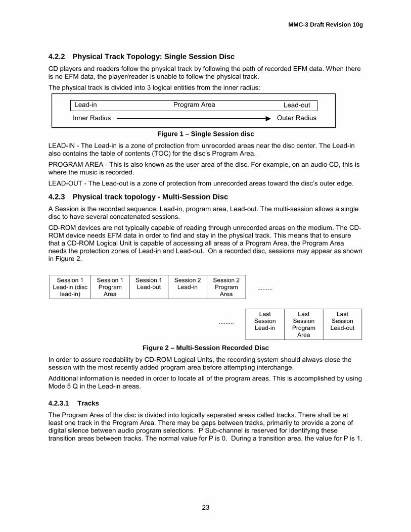
MMC-3 Draft Revision 10g
23
4.2.2 Physical Track Topology: Single Session DiscCD players and readers follow the physical track by following the path of recorded EFM data. When thereis no EFM data, the player/reader is unable to follow the physical track.The physical track is divided into 3 logical entities from the inner radius:
Figure 1 – Single Session discLEAD-IN - The Lead-in is a zone of protection from unrecorded areas near the disc center. The Lead-inalso contains the table of contents (TOC) for the disc�s Program Area.PROGRAM AREA - This is also known as the user area of the disc. For example, on an audio CD, this iswhere the music is recorded.LEAD-OUT - The Lead-out is a zone of protection from unrecorded areas toward the disc�s outer edge.
4.2.3 Physical track topology - Multi-Session DiscA Session is the recorded sequence: Lead-in, program area, Lead-out. The multi-session allows a singledisc to have several concatenated sessions.CD-ROM devices are not typically capable of reading through unrecorded areas on the medium. The CD-ROM device needs EFM data in order to find and stay in the physical track. This means that to ensurethat a CD-ROM Logical Unit is capable of accessing all areas of a Program Area, the Program Areaneeds the protection zones of Lead-in and Lead-out. On a recorded disc, sessions may appear as shownin Figure 2.
Session 1Lead-in (disc
lead-in)
Session 1Program
Area
Session 1Lead-out
Session 2Lead-in
Session 2Program
Area·········
·········Last
SessionLead-in
LastSessionProgram
Area
LastSessionLead-out
Figure 2 – Multi-Session Recorded DiscIn order to assure readability by CD-ROM Logical Units, the recording system should always close thesession with the most recently added program area before attempting interchange.Additional information is needed in order to locate all of the program areas. This is accomplished by usingMode 5 Q in the Lead-in areas.
4.2.3.1 TracksThe Program Area of the disc is divided into logically separated areas called tracks. There shall be atleast one track in the Program Area. There may be gaps between tracks, primarily to provide a zone ofdigital silence between audio program selections. P Sub-channel is reserved for identifying thesetransition areas between tracks. The normal value for P is 0. During a transition area, the value for P is 1.
Outer Radius
Lead-in Program Area Lead-out
Inner Radius

MMC-3 Draft Revision 10g
24
4.2.3.2 Frame AddressingCD was originally developed for playing digital audio that has two channels of 16-bit samples at 44.1KHz.The number of frames per second of play is 75:
4 bytes/Sample*44 100 Samples/second = 176 400 bytes/second176 400 bytes/second / 2 352 bytes/frame = 75 frames/second
Given this, CD frames are addressed in terms of audio play time, i.e. Minute, Second, and Frame (MSF).The traditional value of 60 seconds per minute is followed.In all cases, when an address appears as part of the CD format, it is in MSF format using 2 bcd digits pertime unit. This limits the time addressing on the disc to 99bcd minutes. The representation for a timebased address is MM:SS:FF, where MM = minutes, SS = seconds, and FF = frames.Addressing in the program area begins with 00:00:00. This advances up through the Lead-out.The last frame in the Lead-in is 99:59:74 and decreases as the physical track is followed toward thecenter of the disc. The Lead-in is typically 3 to 4 minutes in length.
4.2.3.3 Q Sub-channelSince an audio CD frame has no address field built into the main channel, the address is carried in the QSub-channel. Q Sub-channel may also carry information about the logical structure of the disc, discidentification, and music track identification. The general format of a Q Sub-channel record is shown inTable 6.
Table 6 – Q Sub-channel record format
Field name DefinitionsS0, S1 Sub-channel Synchronization
CONTROL The Control Field has 4 bits that define the type of information in theframe:00x0b = 2 audio channels without pre-emphasis00x1b = 2 audio channels with pre-emphasis of 50/15 µs10x0b = 4 audio channels without pre-emphasis10x1b = 4 audio channels with pre-emphasis of 50/15 µs01x0b = Data track, recorded uninterrupted01x1b = Data track, recorded increment11xxb = reservedxx0xb = digital copy prohibitedxx1xb = digital copy permittedThe bits of the control field (except for the copy bit) may change during apause (X=00) of at least 2 seconds and during the Lead-in area only.
ADR 4 bits of identification for DATA-Q. This is also known as the Mode (ADR)Q.
DATA Q 72 bits of dataCRC A 16 bit CRC for the Control, ADR, and DATA-Q Fields. On the disc the
CRC bits are inverted. The remainder has to be checked at zero.Polynomial = P(X)=X16+X12+X5+1
Because the sync bits and the two bytes of CRC are overhead, the valid Q information length is actually10 bytes.

MMC-3 Draft Revision 10g
25
4.2.3.4 Q Sub-channel in the Program AreaDuring the program area 3 types of Q Sub-channel may be encountered, Mode-1 Q, Mode-2 Q, or Mode-3 Q.
4.2.3.4.1 ADR=1 (0001b) – Mode-1 QMode 1Q occupies at least 9 out of 10 successive CD frames. Mode-1 Q in the program area is alsoreferred to as current position Q. The Mode-1 Q format during data and audio tracks is shown in Figure 3.
ADR DATA-Q0001 TNO INDEX MIN SEC FRAME ZERO AMIN ASEC AFRAME
Figure 3 – Q Sub-channel Mode-1 Format recorded in Program Area
TNO = 01 to 99bcd is the track numberINDEX = 00 to 99bcd is the Index to TNO. An audio track may be divided into
up to 99 sections, identified by a non-zero index. The first indexedarea in a track shall be 01. Most audio discs have only one indexedarea per track. The pre-gap is the part of a track-to-track gap thatbelongs to the following track. In a track�s pre-gap, the track numberis that of the following track and the INDEX is 00.
MIN, SEC, FRAME = Is the relative time within the track encoded as 6 BCD digits. This is00:00:00 at track start and advances through the track. During thepre-gap the time decreases.
ZERO = 8 bits of zero (00000000b)AMIN, ASEC, AFRAME = Is the program area absolute time address expressed in 6 BCD
digits.
4.2.3.4.2 ADR=2 (0010b) – Mode-2 QMode-2 Q is optional. If Mode-2 Q is present, it shall occupy 1 out of each 100 successive frames. TheMode-2 Q data format is shown in Figure 4.
ADR DATA-Q0010 N1 N2 N3 N4 N5 N6 N7 N8 N9 N10 N11 N12 N13 ZERO AFRAME
Figure 4 – Q Sub-channel Mode-2 FormatThe DATA-Q field is 52 bits long, organized as 13 nibbles (N1 � N13), each carrying a single BCD digit.The resulting BCD string is the Media Catalog Number (MCN). The catalog number does not change on adisc. In case no catalog number is encoded according to the UPC/EAN code, N1 - N13 are all zero, orMode-2 can be deleted from the disc.The ZERO field contains 12 bits of zero. (000000000000b)AFRAME is as defined in Q Sub-channel Mode-1 (two BCD digits running from 00 to 74). During theLead-in (TNO = 00), these 8 bits are zero.

MMC-3 Draft Revision 10g
26
4.2.3.4.3 ADR=3 (0011b) – Mode-3 QMode-3 Q is optional. If Mode-3 is present, it occupies at least 1 out of 100 successive sub-coding blocks.Mode-3 is used to give a unique number to an audio track. This is done by means of the InternationalStandard Recording Code (ISRC). The ISRC, as recorded on the media, is defined in Figure 5. If noISRC is used, Mode-3 shall be deleted. During the Lead-in and Lead-out, Mode-3 is not present on thedisc. The ISRC may only change immediately after the Track Number (TNO) has been changed. TheMode-3 data format is shown in Figure 5.
ADR DATA-Q
0011 I1 I2 I3 I4 I5 0 0 I6 I7 I8 I9 I10 I11 I12 ZERO AFRAME
Figure 5 – Q Sub-channel, Mode-3 FormatThe Country-Code is given in fields I1 through I2, the owner-code in fields I3 - I5, The year of recording infields I6 - I7 and the I8 through I12 contain the serial number of the recording. The characters I1 - I5 are6-bit cells, coded as shown in Table 7. The characters I6 - I12 are coded in 4 bit BCD numbers.I1 - I12 define the ISRC.The ZERO Field contains 4 bits of zero. (0000b)AFRAME is defined in Q Sub-channel Mode-1 Q (two BCD digits running from 00 to 74). During the Lead-in area (TNO = 00), these 8 bits are zero.
Table 7 – ISRC 6 bit character codes (in hexadecimal)
CHAR CODE CHAR CODE
0 00 I 191 01 J 1A2 02 K 1B3 03 L 1C4 04 M 1D5 05 N 1E6 06 O 1F7 07 P 208 08 Q 219 09 R 22A 11 S 23B 12 T 24C 13 U 25D 14 V 26E 15 W 27F 16 X 28G 17 Y 29H 18 Z 2A

MMC-3 Draft Revision 10g
27
4.2.3.5 Q Sub-channel in the Lead-out AreaQ Sub-channel in the Lead-out area is similar to Q Sub-channel in the program area. The differences are:Mode-1 Q Sub-channel: TNO = AAh, INDEX = 01bcdMode-2 Q Sub-channel: No differences.No other Q Sub-channel modes are allowed in the Lead-out area.
4.2.3.6 Q Sub-channel in the Lead-in AreaQ Sub-channel in the Lead-in area is referred to as the Table of Contents (TOC).Three modes of Q are allowed in the Lead-in area: Mode-1 Q, Mode-2 Q, and Mode-5 Q.
4.2.3.6.1 Mode-1 QThe Mode-1 Q format during the Lead-in is shown in Figure 6. TNO is always 00 during the Lead-in andZERO is always 00 during the Lead-in. Variations of Mode-1 Q are defined by the value of POINT.
ADR DATA-Q0001 TNO=00 POINT MIN SEC FRAME ZERO=00 PMIN PSEC PFRAME
Figure 6 – Q Sub-channel Mode-1 Format recorded in Lead-inPOINT = 01bcd � 99bcd is the track number of the track being defined.
MIN, SEC, FRAME = Running time in the Lead-in, encoded as BCDPMIN, PSEC, PFRAME = Track start time, encoded as BCD
POINT = A0hMIN, SEC, FRAME = Running time in the Lead-in, encoded as BCDPMIN = Track number of the first track in the program area, encoded as BCDPSEC = Program area format: 00h - CD-DA or CD-ROM
10h - CD-I20h - CD-ROM-XA
PFRAME = 0
POINT = A1hMIN, SEC, FRAME = Running time in the Lead-in, encoded as BCDPMIN = Track number of the last track in the program area, encoded as BCDPSEC, PFRAME = 0, 0
POINT = A2hMIN, SEC, FRAME = Running time in the Lead-in, encoded as BCDPMIN, PSEC, PFRAME = Start time of Lead-out, encoded as BCD

MMC-3 Draft Revision 10g
28
4.2.3.6.2 Mode-2 QMode-2 Q Sub-channel is defined the same in the Lead-in, program area and Lead-out.
4.2.3.6.3 Mode-5 QMode-5 Q Sub-channel provides additional information about CD-R and CD-RW recordings. The formatof a Mode-5 Q Sub-channel is shown in Figure 7. TNO is always 00 during the Lead-in. Variations ofMode-5 Q are defined by POINT.
ADR DATA-Q0101 TNO POINT MIN SEC FRAME ZERO PMIN PSEC PFRAME
Figure 7 – Q Sub-channel Mode-5 Format recorded in Lead-inPOINT=01�40 (Audio only: This identifies a specific playback skip interval)
MIN, SEC, FRAME = Skip interval stop time in 6 BCD digitsZERO = 00PMIN, PSEC, PFRAME = Skip interval start time in 6 BCD digits
POINT = B0h (multi-session disc)MIN, SEC, FRAME = the start time for the next possible session�s program area. A final
session is indicated MIN, SEC, FRAME = FFh:FFh:FFh or when theMode-5 point B0 is absent.
ZERO = the number of different Mode-5 pointers present.PMIN, PSEC, PFRAME = the maximum possible start time of the outermost Lead-out
POINT=B1h (Audio only: This identifies the presence of skip intervals)MIN, SEC, FRAME = 00, 00, 00ZERO = 00PMIN = the number of skip interval pointersPSEC = the number of skip track assignments in POINT=B2, B3, and B4PFRAME = 00
POINT=B2h, B3h, B4h (Audio only: This identifies tracks that should be skipped during playback)MIN 01-99bcd, track number to skip upon playbackSEC 00-99bcd, track number to skip upon playback,
00 if no skip track is specifiedFRAME 00-99bcd, track number to skip upon playback,
00 if no skip track is specifiedZERO 00PMIN 00-99bcd, track number to skip upon playback,
00 if no skip track is specifiedPSEC 00-99bcd, track number to skip upon playback,
00 if no skip track is specifiedPFRAME 00-99bcd, track number to skip upon playback,
00 if no skip track is specified
Note: Skip intervals are seldom written by recorders and typically ignored by readers.

MMC-3 Draft Revision 10g
29
POINT = C0h (Together with POINT=B0h, this is used to identify a multi-session disc)MIN, SEC, FRAME = ATIP values from Special Information 1, ID=101 (See )ZERO = 00PMIN, PSEC, PFRAME = Start time of the first Lead-in area of the disc
4.2.3.7 CD Main Channel Block FormatsAlthough some are rarely used, there are 6 main channel frame formats defined. Audio blocks arerecorded unmodified. Data blocks are given a synchronization field at the beginning of the block. Thepattern is shown in Figure 8.
00h FFh FFh FFh FFh FFh FFh FFh FFh FFh FFh 00h
Figure 8 – Synchronization Field patternThe synchronization field is followed by a 4 byte header defined in Table 8. After the sync pattern theremaining bytes of the data block are scrambled with a feedback mechanism. This is done with a 15-bitshift register fed back according to the polynomial X15+X+1.
Table 8 – Sync Pattern Block Header
Header Offset Header Byte Content
0 Minute Program area time of block, minute component (00-79 bcd)
1 Second Program area time of block, second component (00-59 bcd)
2 Frame Program area time of block, frame component (00-74 bcd)
3 Mode Bits 1, 0 = Data Mode, Bits 7 -.5 = block indicator field, Bits4 - 2 = Reserved. When Bits 7 � 5 = 000 indicates user data.
Mode byte Format is shown below:
Bits 7, 6, 5 = 000 - User Data block= 001 - Fourth Run-in block= 010 - Third Run-in block= 011 - Second Run-in block= 100 - First Run-in block= 101 - Link block. Physical linking of EFM data= 110 - Second Run-out block= 111 - First Run-out block
Bits 4, 3, 2 = 000 - ReservedBits 1, 0 = 00 Mode 0 Data
= 01 - Mode 1 Data= 10 - Mode 2 Data= 11 - Reserved

MMC-3 Draft Revision 10g
30
1.1.1.1.1 Block Format for AudioAudio is streamed, so only user data resides within the frame. See the READ CD command descriptionfor byte ordering.
4.2.3.7.1 Block Format for Mode 0 DataMode 0 is a rarely used format as it is zero filled in the entire user data area. Mode zero data (Table 9)has the following format.
Table 9 – Mode Zero Data Format
Byte Offset Field Length Content
0 12 Data Block Sync pattern12 3 Block MSF address (BCD)15 1 Data mode = 016 2 336 User data (each byte is zero)
4.2.3.7.2 Block Format for Mode 1 DataMode 1 data (Table 10) is most prevalent in CD-ROM applications. The sync pattern, header and userdata are protected by a 32-bit CRC. Two additional layers of error correction, P and Q, collectively calledLevel 3 correction cover the header and user data. This is also referred to as Layered error correction (L-EC or C3).
Table 10 – Mode 1 Data Format
Byte Offset Field Length Content
0 12 Data Block Sync pattern12 3 Block MSF address (BCD)15 1 Data mode = 0116 2 048 User data
2064 4 CRC (P = (X16+X15+X2+X1)*(X16+X2+X+1)) Bytes 0 -2063
2068 8 Zero fill2076 172 P parity symbols2248 104 Q parity symbols
The coverage of the CRC is the sync pattern, Header, and the User Data.The coverage of Level 3 P is Header, User Data, CRC, and the zero fill.The coverage of Level 3 Q is Header, User Data, CRC, the zero fill, and the P parity.

MMC-3 Draft Revision 10g
31
4.2.3.7.3 Block Format for Mode 2 DataMode 2 data blocks have two types: formless and formed. Mode 2 formed blocks have two forms: form 1and form 2.
4.2.3.7.3.1 Block Format for Mode 2 formless DataThe Mode 2 formless block format (Table 11) is rarely used. There is no defined CRC or additionalcorrection.
Table 11 – Mode 2 formless block format
Byte Offset Field Length Content
0 12 Data Block Sync pattern12 3 Block MSF address (BCD)15 1 Data mode = 216 2 336 User data
4.2.3.7.3.2 Block Format for Mode 2 form 1 DataThe Mode 2 form 1 block format (Table 12) is regularly used in recorder applications and Video CDmovies. The Mode 2 form 1 format is very similar to Mode 1 format. The differences are:
• The 8 zero fill bytes have been moved to between the header and user data as two copies of a 4 bytesub-header.
• The CRC, P-parity, and Q-parity do not cover the block header. This assures the ability of relocatingdata, including all parity symbols.
Table 12 – Mode 2 form 1 data format
Byte Offset Field Length Content
0 12 Data Block Sync pattern12 3 Block MSF address (BCD)15 1 Data mode = 216 4 Sub-header, first copy20 4 Sub-header, second copy24 2 048 User data
2072 4 CRC (P = (X16+X15+X2+X1)*(X16+X2+X+1)) Bytes 16- 2071
2076 172 P parity symbols2248 104 Q parity symbols
The format of the sub-header is shown in Table 13.

MMC-3 Draft Revision 10g
32
Table 13 – Mode 2 form 1 sub-header format
Sub-HeaderByte
Byte Name Definition
0 File number Identifies the file to which the block belongs1 Channel number Playback channel selection2 Sub-mode Bit 7: End-of-File
Bit 6: Real-time blockBit 5: Form (0 = Form 1, 1 = Form 2)Bit 4: Trigger BlockBit 3: Data BlockBit 2: Audio Block (not traditional CD-DA audio)Bit 1: Video BlockBit 0: End-of-Record
3 Coding information
4.2.3.7.3.3 Block Format for Mode 2 form 2 DataMode 2 form 2 data (Table 14) is regularly used in Video CD movies. The data is optionally covered byCRC within the last 4 bytes of the block.
Table 14 – Mode 2 form 2 data format
Byte Offset Field Length Content
0 12 Data Block Sync pattern
12 3 Block MSF address (BCD)
15 1 Data mode = 2
16 4 Sub-header, first copy
20 4 Sub-header, second copy
24 2 324 User data
2348 4 Optional CRC Bytes 16 - 2347
4.2.3.8 CD Recordable and CD ReWritable Media StructureAn unrecorded CD-R or CD-RW disc does not have any EFM present to find the physical track in thetraditional way of CD-ROM Logical Units. A blank CD-R or CD-RW is not smooth, it is pre-grooved andthe groove has a built-in wobble for the purpose of defining and finding the physical track.The wobble is a 22.05kHz signal (at 1X) modulated with digital information. The time position within thepre-groove is contained in each pre-groove frame of 42 bits. This is known as Absolute Time In Pre-groove (ATIP) (Table 15).

MMC-3 Draft Revision 10g
33
Table 15 – ATIP format
ATIP Frame Item Content
Sync (4 bits) Synchronization nibble
Minute (8 bits) Absolute disc time: Minute (BCD)
Second (8 bits) Absolute disc time: Seconds (BCD)
Frame (8 bits) Absolute disc time: Frame (BCD)
CRC (14 bits) CRC protection
In the area that is expected to be the disc�s Lead-in, additional information is interleaved betweenpositional ATIP frames. The additional information provided is:
• First possible start time for disc Lead-in (TOC)
• Last possible start time for disc Lead-out
• Special information about recording permissions
• Power and speed requirements for recording the medium
• CD-R vs. CD-RW medium
4.2.3.8.1 CD-R/RW Disc ManagementCD-R/RW discs have two additional areas prior to the first Lead-in, the Power Calibration Area (PCA),and the Program Memory Area (PMA). See Figure 9.PCA - The Power Calibration Area (PCA) is present only for CD-R and CD-RW media for the purpose ofwrite power calibration. The PCA is divided into two areas: the test area and the count area. The test areais divided into 100 calibration partitions. The count area is an accounting area for recording usage of thetest area.PMA - The Program Memory Area is present only for CD-R and CD-RW media for the purpose ofaccounting for the usage of user data areas on the medium. This information is contained only within theSub-channel of the PMA frames. The main channel content is not defined within the PMA.Update the PMA means to update the PMA on the disc or to update the PMA Cache, that shall be writtento the PMA on the disc prior to the removing the disc from the Logical Unit. PMA Caching is vendorspecific.
Figure 9 – CD-R and CD-RW medium
C enter
PCA
PCA C ount 26m m Spec ial optical sensor used for th is loc ation
PMA TO C(L1)
User B loc ks
Lead-out TO C
First S ess ion Sec ond S ession
Partially rec orded D isc TO C inform ation c ontained in the PM A
The PC A is used for P ower C alib ration N ote that it c an be us ed only 100 tim es for CD-R M edia

MMC-3 Draft Revision 10g
34
4.2.3.8.2 PMA Q Sub-channelThe PMA is a temporary TOC to be used as a disc is being recorded in increments. The format of the QSub-channel for PMA entries is similar to those in the Lead-in.The PMA is recorded in groups of 10 frames called a PMA unity. If any of the frames in a unity isrecorded, then all frames in the unity shall be recorded. A given PMA entry shall appear either 5 or 10times within a unity.Q Sub-channel in the PMA has the general form shown in Figure 10.
ADR DATA-Q0001-0110 TNO POINT MIN SEC FRAME ZERO PMIN PSEC PFRAME
Figure 10 – PMA, Q Sub-channel
Mode-1 Q Sub-channel in the PMA is a TOC item:TNO = 00POINT = Track number encoded as two BCD digits.ZERO = 00-09bcd is a label of the frame number in the PMA unityMIN, SEC, FRAME = Track stop time in 6 BCD digits.PMIN, PSEC, PFRAME = Track start time in 6 BCD digits.
Mode-2 Q Sub-channel in the PMA is a Disc Identification item (optional):TNO = 00POINT = 00ZERO = 00-09bcd is a label of the frame number in the PMA unityMIN, SEC, FRAME = Disc identification as a 6 BCD digit number.PMIN = 00PSEC = Sessions format:
00 - CD-DA or CD-ROM, 10 - CD-I, 20 - CD-ROM-XAPFRAME = 00
Mode-3 Q Sub-channel in the PMA is a Skip track item (optional, audio only):TNO = 00POINT = 01-21bcd is the mode-3 index of this itemZERO = 00-09bcd is a label of the frame number in the PMA unityMIN = 01-99bcd track number to skip upon playbackEach of the following:SEC, FRAMEPMIN, PSEC, PFRAME
==
00 if no skip track is specified01-99bcd (each byte) track number to skip upon playback

MMC-3 Draft Revision 10g
35
Mode-4 Q Sub-channel in the PMA is an unskip track item (optional, audio only):TNO = 00POINT = 01-21bcd is the mode-4 index of this itemZERO = 00-09bcd is a label of the frame number in the PMA unityMIN = 01-99bcd track number to unskip upon playbackEach of the following:SEC, FRAMEPMIN, PSEC, PFRAME
==
00 if no unskip track is specified01-99bcd (each byte) track number to unskip upon playback
Mode-5 Q Sub-channel in the PMA is a skip interval item:TNO = 00POINT = 01-40bcd is the mode-5 index of this itemZERO = 00-09bcd is a label of the frame number in the PMA unityMIN, SEC, FRAME = Skip interval stop time in 6 BCD digits.PMIN, PSEC, PFRAME = Skip interval start time in 6 BCD digits.
Mode-6 Q Sub-channel in the PMA is an �unskip interval� item:TNO = 00POINT = 01-40bcd is the mode-6 index of this itemZERO = 00-09bcd is a label of the frame number in the PMA unityMIN, SEC, FRAME = Unskip interval stop time in 6 BCD digits.PMIN, PSEC, PFRAME = Unskip interval start time in 6 BCD digits.
4.2.3.9 RecordingBlank CD-R is not randomly writable. CD-RW is limited in its random write capability. Due to theinterleaved nature of CD frames, blank media shall be recorded in groups of frames with linkage forappending new recording.There are two methods for linking separate writes on CD-R or CD-RW:Audio - Linkage occurs within a single frame time. This assures that locating the linkage frame by its Q ata later time is nearly impossible.Data - Since it is necessary to locate exact boundaries of user blocks, additional padding is insertedaround the linkage frame. The collection of the link block, the pad blocks, and the user blocks is called aPacket. The format of the packet is shown in Figure 11.
LinkBlock
Run-inBlock 1
Run-inBlock 2
Run-inBlock 3
Run-inBlock 4
User Data Blocks Run-outBlock 1
Run-outBlock 2
Figure 11 – Packet Format

MMC-3 Draft Revision 10g
36
Bits 5, 6, and 7 of the block�s mode byte (see Table 16) uniquely identify blocks.
Table 16 – Block Identifier bits
Mode Byte Bits 7, 6, 5 Block
000 User Data001 Run-in block 4010 Run-in block 3011 Run-in block 2100 Run-in block 1101 Link block110 Run-out block 2111 Run-out block 1
See 4.2.3.7 for a detailed definition of the Mode Byte. Main channel user data should be all zeros.Only entire packets may be rewritten on CD-RW media.There are 2 types of recording on CD-R: Uninterrupted and Incremental. Incremental recording requireslinking, whereas uninterrupted does not.Disc At Once is the only type of uninterrupted recording and is a special case of Session At Once. Therecording begins at the start of the Lead-in and stops only when the last block of the Lead-out is written.The PMA is not written. No linking is required.There are 5 types of incremental recording:Session At Once - The recording begins at the start of the Lead-in of the next session and stops onlywhen the last block of that session�s Lead-out is written. The PMA is constructed and written as aseparate write action. Linking between sessions is required.Reserve Track - User data is not necessarily written. The PMA is written for the purpose of defining a newtrack.Track At Once - A single packet that includes the pre-gap of the track and all of the track�s user data.Variable Packet - A variable number of user blocks is written between data linkage blocks. A variablepacket shall be a part of the user data area of a track.Fixed Packet - A fixed number of user blocks is written between the user blocks. A fixed packet shall be apart of the user data area of a track.
4.2.3.10 The Track Descriptor BlockThe Track Descriptor Block (TDB) is required for Track at Once or Packet recording. When the TDB ispresent, each block of the pre-gap of a track is a TDB. When a track is only reserved for Track At Oncerecording, recording of the TDB is deferred until the track data is written. When a track is reserved foreither sort of packet recording, the TDB shall be written as a single packet upon reservation.The TDB contains main channel information about the track recording and optionally contains a history oftracks that preceded the TDB.The TDB begins with an 8 byte header (Table 17). The TDB header is followed by one or more TrackDescriptor Units (TDU) (Table 18).

MMC-3 Draft Revision 10g
37
Table 17 – Track Descriptor Block (TDB) header
BitByte
7 6 5 4 3 2 1 0
0 54h (ASCII �T�)
1 44h (ASCII �D�)
2 49h (ASCII �I�)
34
Pre-gap Length encoded BCD
5 Reserved Current
6 Lowest Track Number Listed (BCD)
7 Highest Track Number Listed (BCD)
8 One or more Track Descriptor Unit(s) (TDU):n
Pre-gap length is given in number of blocks.The Current bit, when set to 1, indicates that only the TDU for the current track is present. When clearedto 0, indicates that a TDU for tracks with numbers smaller than or equal to the current track, are present.
Table 18 – Track Descriptor Unit (TDU) Format
BitByte
7 6 5 4 3 2 1 0
0 Track Number (BCD)
1 Recording method
2 (MSB)
3 Fixed Packet Size in blocks (BCD)
4 (LSB)
5 Reserved
… Reserved
15 Reserved
Recording method is coded as follows:00h Audio track written TAO80h Data track written TAO90h incrementally written data track, variable packets91h incrementally written data track, fixed packetsFixed Packet size is filled with FFFFFFh whenever the recording method is not fixed packet.

MMC-3 Draft Revision 10g
38
4.2.4 High Speed CD-RW media recordingHigh speed CD-RW is defined in System Description ReWritable Compact Disc Systems, part III Volume2: CD-RW (Orange Book part III, Vol. 2). High Speed CD-RW recording speed ranges are from 4x to 10xrecording and also allows CAV recording. Upon CAV recording, write speed needs to be set for eachtrack. If the Logical Unit is not capable of recording continuous track in CAV, then the Logical Unit shalluse CLV mode with initial speed of CAV recording. For example, if the 4x-10x CAV recording is attemptedfor TAO mode, but the Logical Unit does not support CAV for TAO mode, then the Logical Unit shallchoose 4x CLV recording for that track. This condition is not considered as an error.High speed CD-RW media cannot be recorded using Logical Units that comply with only Orange BookPart 3 volume 1. Upon write attempt to the High speed CD-RW media using Orange Book Part 3 volume1 complying Logical Unit, some Logical Units return CHECK CONDITION Status and set SK/ASC/ASCQvalues to either ILLEGAL REQUEST/WRITE PROTECTED or MEDIUM ERROR/NO SEEK COMPLETE.The recommended SK/ASC/ASCQ values for this case are ILLEGAL REQUEST/CANNOT WRITEMEDIUM - INCOMPATIBLE FORMAT.In order to minimize the impact to the large number of MMC-1 based CD-R/RW Logical Units andsoftware, extensions of SET CD SPEED Command and CD/DVD Capabilities & Mechanical Status ModePage (2Ah) are defined as an optional Feature. Also SET STREAMING Command and GETPERFORMANCE Command for CD-R/RW implementation are defined.Command Sequence example:Upon media insertion, Initiator issues READ TRACK/RZONE INFORMATION Command to find the nextwritable address. Then either CD/DVD Capabilities & Mechanical Status Mode Page (2Ah) or GETPERFORMANCE Command are used to identify the Logical Unit�s capability for the mounted media.Host then issues either SET CD SPEED Command or SET STREAMING Command for the track to berecorded. Also the Initiator sets an appropriate Write Parameters, and ready to write data.
4.2.5 CD Audio error reportingAudio play commands (PLAY AUDIO (10), PLAY AUDIO (12), PLAY AUDIO MSF) with the immediate bitset in the audio control mode page return status as soon as the command has been validated (that mayinvolve a seek to the starting address). The playback operation continues and may complete withoutnotification to the Initiator. Error termination of audio operations shall be reported to the Initiator byreturning CHECK CONDITION STATUS to the next command (except for REQUEST SENSE, INQUIRY,GET CONFIGURATION, and GET EVENT/STATUS NOTIFICATION). The deferred error sense data isused to indicate that the error is not due to the current command.The status of the play operation may be determined by issuing a REQUEST SENSE command. Thesense key is set to NO SENSE, the ASC is set to NO ADDITIONAL SENSE DATA and the audio status(see ) is reported in the additional sense code qualifier field.
4.2.6 CD ready condition/not ready conditionThe ready condition occurs after a disc is inserted and the Logical Unit has performed its initializationtasks. These tasks may include reading the Table of Contents from the media. Table 19 defines the NotReady Error reporting for each command. A not ready condition shall occur only for the following reasons:a) There is no medium mounted.b) The Logical Unit is unable to load or unload the medium.c) The Logical Unit is unable to recover the Table of Contents.d) The controller cannot select the Logical Unit.e) As otherwise described in the command operation.

MMC-3 Draft Revision 10g
39
Table 19 – Not Ready Error Reporting (by command)
Command Name OperationCode
Return NotReady Status
Time-out
BLANK A1h Yes Group 2 Note 1CLOSE TRACK/SESSION 5Bh Yes Group 2 Note 1SYNCHRONIZE CACHE 35h Yes Group 2FORMAT UNIT 04h Yes Group 2 Note 1GET CONFIGURATION 46h No Not AllowedGET EVENT/STATUS NOTIFICATION 4Ah No Not AllowedGET PERFORMANCE ACh No Group 1INQUIRY 12h No Not AllowedLOAD/UNLOAD MEDIUM A6h Yes Group 1 Note 1LOCK/UNLOCK CACHE 36h No Group 2LOG SELECT/SENSE 4Ch,4Dh No Group 1MECHANISM STATUS BDh No Group 1MODE SELECT 55h, 15h No Group 1MODE SENSE 5Ah, 1Ah No Group 1PAUSE/RESUME 4Bh Yes Group 1PLAY AUDIO 45h, A5h Yes Group 1PLAY AUDIO MSF 47h Yes Group 1PLAY CD BCh Yes Group 1PREFETCH 34h Yes Group 1PREVENT ALLOW MEDIUM REMOVAL 1Eh No Group 1READ 28h, A8 Yes Group 1READ BUFFER 3Ch No Group 1READ BUFFER CAPACITY 5Ch No Group 1READ CAPACITY 25h Yes Group 1READ CD BEh Yes Group 1READ CD MSF B9h Yes Group 1READ DISC INFORMATION 51h Yes Group 1READ DVD STRUCTURE ADh Yes Group 1READ FORMAT CAPACITIES 23h No Group 1READ SUB-CHANNEL 42h Yes Group 1

MMC-3 Draft Revision 10g
40
Table 18 (continued) – Not Ready Error Reporting (by command)Command Name Operation
CodeReturn Not
Ready StatusTime-out
READ TOC/PMA/ATIP 43h Yes Group 1READ TRACK INFORMATION 52h Yes Group 1RECEIVE DIAGNOSTIC RESULTS 1Ch No Not AllowedRELEASE 17h, 57h No Not AllowedREPAIR TRACK 58h Yes Group 1REPORT KEY A4h Yes Group 1REPORT LUNS A0h No Group 1REQUEST SENSE 03h No Not AllowedRESERVE 16h, 56h No Not AllowedRESERVE TRACK 53h Yes Group 2REZERO UNIT 01h Yes Group 1SCAN BAh Yes Group 1SEEK 2Bh Yes Group 1SEND CUE SHEET 5Dh No Group 1SEND DIAGNOSTICS 1Dh No Not AllowedSEND DVD STRUCTURE BFh No Group 1SEND EVENT A2h Yes Group 1SEND KEY A3h Yes Group 1SEND OPC INFORMATION 54h No Group 1SET CD SPEED BBh No Group 1SET READ AHEAD A7h Yes Group 1SET STREAMING B6h Yes Group 1START STOP UNIT 1Bh Yes Group 1STOP PLAY/SCAN 4Eh Yes Group 1TEST UNIT READY 00h Yes Group 1VERIFY 2Fh, AFh Yes Group 2WRITE 2Ah, AAh Yes Group 1WRITE AND VERIFY 2Eh Yes Group 1
Note 1: With the IMMED bit set, Time Out is not allowed and shall be completed within the Group 1time.
4.2.7 Sensing support for CD-audio commands.The preferred method of sensing support for CD audio is the implementation of the GETCONFIGURATION command (sub-clause 5.5). For legacy implementations, if any commands related toaudio operations are implemented, then the PLAY AUDIO (10) command (sub-clause 5.11) shall beimplemented to allow a method for the Initiator to determine if audio operations are supported. A targetresponding to a PLAY AUDIO (10) command that has a transfer length of zero, with CHECK CONDITIONSTATUS, and setting the sense key to ILLEGAL REQUEST does not support audio play operations.

MMC-3 Draft Revision 10g
41
4.2.8 The CD-MRW FormatThe Mount Rainier Technical Group is an industry organization that has defined a defect managed formatfor standard CD-RW media. The format is named CD-MRW (Mount Rainier RW). Details of the discformat are found in CD-MRW Defect Management & Physical Formatting (see sub-clause 2.2).From the perspective of the CD-RW System Description, the entire capacity of a MRW disc consists of asingle session containing a single track of 32 sector fixed packets.
Figure 12 � Track/Session Structure of a CD-MRW DiscThere are differences.
4.2.8.1 Additional StructureThe MRW disc does have this format, but the CD-MRW Defect Management & Physical Formattingrequires additional features, built upon the basic format (Figure 13).
Lead-in, Part A TOC, no changeLead-in, Part B TOC (in sub-channel Q) along with MTA (information is stored in main
channel). Prior to CD-MRW, the lead-in has always been recordedtrack-at-once. With this new format, it is recorded as fixed packets. TheMTA use begins with the packet that precedes the pre-gap. Whenneeded, the MTA grows backward toward the disc center.
Program Area, Part A Track 1 pre-gap has a fixed size of 150 sectors. The TDB identifies thetrack as a fixed packet track with packet size = 32.
Program Area, Part B The General Application Area (GAA) is a segment of the track that isNOT covered by the defect management system. This is fixed at 32packets (2 MB of user space).
Program Area, Parts Cx The Defect Managed Area (DMA) consists of DMA segments, Cx. EachCx consists of a spares area (SA) followed by a data area (DA). EachSA shall contain 8 packets. Each DA within C1, C2, �, Cn-1, shallcontain 136 packets for primary data. Cn may contain less than 136packets, based upon disc capacity. The DMA is the logicalconcatenation of all DAs.
Program Area, Part D STA: 33 packets reserved for secondary copies of the MTA structures.Lead-out, Part A Lead-out, no change
Figure 13 – The Additional Structure of CD-MRW
The number of Cx is determined as follows: P = number of 32 sector fixed packets available in theformatted track 1. The number of packets in all Cx is Pt = P � GAA size � STA size = P � 65. When Pt isdivided by 144 (=8 + 136), there is a quotient Q and remainder R.
If R ≤ 8, then Q = n, the DA size for each Cx is 136, and the lead-out begins R packets sooner.
Lead-in Lead-out
Lead-in Track 1: 32 Sector Fixed packets Lead-out
A B C1B D A
Program Area
A C2 Cn��

MMC-3 Draft Revision 10g
42
If R > 8, then Q = n � 1, the DA for C1, C2,...Cn-1 is 136, the DA for Cn is R � 8 packets in length, andthe lead-out is not offset into the program area.The Host�s primary address space is the DMA. By default, an LBA is presumed to refer to this addressspace. Note that LBAs for the DMA do NOT match LBAs for a similarly formatted pre-MRW disc.The GAA is available for compatibility with older systems. The GAA LBA space is 0, 1, 2, 3, �, 1023d.Note that LBAs for the GAA exactly match LBAs for a similarly formatted pre-MRW disc.
4.2.8.1.1 AddressingWhen method 2 addressing is used, the LBA of the first sector of the DMA is (32 + 8)*32 = 1 280d. Table20 shows the inequities with method 2 LBA references:
Table 20 � Method 2/Method 3 Addressing Comparison
Method 2 LBA MRW LBA Method 2 LBA MRW LBA Method 2 LBA MRW LBA
0 GAA 0 1 280 DMA 0 5 888 DMA 4 352
1 GAA 1 1 281 DMA 1 5 889 DMA 4 353
2 GAA 2 1 282 DMA 2 5 890 DMA 4 354
. . . . . .
. . . . . .
1 023 GAA 1 023 5 631 DMA 4 351 10 239 DMA 8 703
The GAA addressing is identical to traditional addressing. The new method of addressing sectors in theDMA is named "method 3 addressing" in the CD-MRW Defect Management & Physical Formatting.There is a small problem: there are two LBA spaces where formerly there was only one. The MRW ModePage is used a the method of specific address space selection. The host may toggle between addressspaces (DMA and GAA) by changing the logical unit�s reference in the MRW Mode Page.
4.2.8.1.2 Host Requests/Logical unit ResponsesThe host may view the MRW disc as a removable magnetic medium with a 2 048 byte sector size. Thismeans that the random read capability of MMC is to be maintained and expanded to include the MRWdisc.Additionally, random write capability shall be added specifically for the MRW disc. Within the logical unit,only the writing of 32 sector fixed packets is allowed. MMC-1 and MMC-2 logical units share thisrestriction with their hosts. When MRW disc is present, the MRW compliant logical unit does not sharethis restriction with its host. This is a simple matter of implementing a read/modify/write for packets.
4.2.8.1.3 GAA ContentsSince devices not compliant with this model will be able to present the GAA accurately, it isrecommended that the GAA be formatted as a ISO 9660 volume containing no directories and exactlyone file named: Read-me.txt with the following contents:
This document is defined in size and content by the Mt. Rainier technical group, for the support ofthe CD-MRW format.If you have a system manufactured before 2002, you will need to contact your PC system oroperating system manufacturer for appropriate software to read this format. Links to supportingsoftware vendors can be found at www.mt-rainier.org.If your system's optical drive carries the CD-MRW logo, and you are seeing this content, pleasecontact your PC system or optical drive manufacturer directly.

MMC-3 Draft Revision 10g
43
4.2.8.1.4 Background FormattingMost of the process for formatting a CD-RW disc into the MRW format is performed in background.During this background formatting process, the disc is available for both read and write access within theLBA Space as it exists after formatting has completed. The MRW capable drive shall perform thenecessary tasks to ensure this access.The user may wish to remove the disc prior to format completion. This is allowed; however, it is requiredthat the medium is written in such a way as to ensure read compatibility with Multi-read capable, read-only devices. This requires that the disc be closed. The format begins again when a host arranges forthe format to be restarted.
4.2.8.2 Streamed WritingThe CD-RW Defect Management & Physical Formatting revision 1.1 defines the method for streamedwriting on CD-MRW formatted discs. This simply disables the defect management system during thestreamed writing, thereby providing a writing method that yields fixed rate data flows principally for videoapplications.The WRITE(12) command is used to control and utilize the streamed write capability. A "streamed" bit inthe command descriptor block declares that the data should be written or read in a streamed way.The READ (12) command is used to read streamed written data. A "streamed" bit in the commanddescriptor block tells the drive to disable use of the defect management system and to ignore data errors.
4.2.8.3 Consequences of a Multi-Volume FormatThe Mount Rainier format is multi-volume. This simply means that a single, physical medium representsmore than a single logical volume. In the case of Mount Rainier, the number of volumes is 2: the GAAand the DMA.
4.2.8.3.1 LBA SpacesThe consequence is that two distinct LBA spaces must be provided and under normal, logical accesses,action on one volume cannot modify data on the other volume. The MRW drive provides a simplemethod to select between address spaces: the MRW Mode Page.When a command references the media by LBA, the result is dependent upon the currently selected LBASpace.
4.2.8.3.2 Features and EventsThe feature sets associated with GAA and DMA are different. Some features are common, but some arealso different.When a MRW formatted (or formatting) disc is mounted, the drive shall always default to the LBA Spaceof the DMA. If the host chooses to select the GAA, then the drive shall generate a Morph Event andchange the set of features that are marked current. Table 21 shows the expected response to a requestfor current features that are expected to be volatile.
Table 21: Currency of Features for GAA and DMA
Feature Currency WithGAA
Currency withDMA
Restricted Overwrite Yes NoIncremental Streaming Writable Yes YesRandom Writable No YesDefect Management No Yes

MMC-3 Draft Revision 10g
44
Some features will be current regardless of the LBA Space selection: Core, Morphing, RemovableMedium, Random Read, Multi-read, Formattable, and Real-time Streaming.

MMC-3 Draft Revision 10g
45
4.3 DDCD ModelThe Double Density CD (DDCD) Media Format is an extension of CD family whose capacity is more thandouble. This capacity is achieved by using a conventional 780 nm laser and using a NA of 0.50 or 0.55,and- reduction of the track pitch (x 1.45)- reduced minimum pit size (x 1.33)
Table 22 � Realization of higher density
Parameter Red Book CD DDCD Factor
Track pitch (um) 1.60 1.10 1.45Length of opticalmarks (3�n�11)
n*0.278 n*0.208 1.33
Program area radius(mm)
(120 mm disc)25-37.5 ( 80 mm disc)
(120 mm disc)24-37.5 ( 80 mm disc)
1.06
Total user bit rate/Channel bit rate:
(CD-ROM Mode 1) 0.284 (CD-ROM Mode 2) 1.00
A DDCD medium is an 80 mm or a 120 mm disc with a continuously recorded physical track beginningfrom a radius of 24 mm and spiraling outward to a radius 37.5 mm or 58 mm.Like a conventional CD Drive/Media there are three types of DDCD Drive/Media, Read Only (DDCD-ROM), Write Once (DDCD-R), and ReWritable (DDCD-RW). The capacities of these media are the same.The DDCD Media Format is not backward compatible with current CD devices
4.3.1 DDCD SpecificationsComparing the new DDCD specifications with those of the conventional CD, some major specificationsare the same, such as the size of the disc. Other specifications indicate that some adaptations have to bemade to the media production process of the DDCD.Error correction and physical addressing require some changes to the decoding/encoding equipment.Table 23 shows some DDCD parameters.

MMC-3 Draft Revision 10g
46
Table 23 – Main Parameters of DDCD
Parameter DDCD-ROM DDCD-R DDCD-RW
Capacity ( 120 mm disc ) [Mbytes] 1 300 1 300 1 300Capacity ( 80 mm disc ) [Mbytes] 400 400 400Wavelength of laser diode [nm] 780 780 780Reference NA [for read] [for write]
> 0.50 > 0.50 0.55
> 0.50 0.55
Data Bit length [um] 0.442 0.442 0.442Channel Bit length [um] 0.208 0.208 0.208Minimum Pit/Mark length [um] 0.62 0.62 0.62Maximum Pit/Mark length [um] 2.29 2.29 2.29Track pitch [um] 1.10 1.10 1.10Sense of disc rotation seen fromreading side
Counterclockwise
Counterclockwise
Counterclockwise
Thickness of the disc [mm] 1.2 1.2 1.2User data per sector [bytes] 2 048 2 048 2 048Error Correction Code CIRC* CIRC* CIRC*Layered ECC Constraint Length 1sector 1sector 1sectorCorrectable burst error length [mm] 3.16 3.16 3.16Scanning velocity at 1X speed [m/s] 0.90 0.90 0.90Channel bit rate [Mbps] 4.3218 4.3218 4.3218User data bit rate at 1X speed [k Bytes/s] 150 150 150
Note: CIRC* is different from the conventional CD. In the DDCD system, the delay parameter �D�of CIRC is extended from 4 to 7 to improve burst error correction ability in case of higherrecording density. The maximum burst error correction ability of CIRC* is extended to 837symbols.
4.3.1.1 Disc StructureThere are three address expressions used in the DDCD system; the Block address contained in thesector header (Physical Sector Number), Subcode-Q channel (Subcode frame time number), and theaddress referred to the blocks of the Initiator system (LBA: Logical Block Address).The address used by the Initiator system starts from 0 to the end of the recorded information on the disc.LBA 0 shall correspond with the sector header address of D300h and the Subcode-Q address of0:12:00:16 (0 hour, 12 minutes, 00 second, 16 frame). Only the Data Area is generally addressable byusing LBA.Subcode-Q areas are addressed in time based address. The representation for a time based address isH:MM:SS:FF, where H = hours, MM = minutes, SS = seconds, and FF = frames. Hour field is 1 digit.MM:SS:FF are 2 digits respectively. When the time based address includes the hours field selectionbetween LBA and H:MM:SS:FF is indicated by the appropriate TIME bit.One Hour is subdivided into 60 Minutes. One Minute is 60 Seconds. One Second is 75 frames. SeeFigure 14.

MMC-3 Draft Revision 10g
47
4.3.1.2 Single Session DiscA Session is a recorded sequence that includes a Lead-in Area, Program Area, and Lead-out Area. TheLead-in / Lead-out Area is a guard area at inner / outer part of the disc. The Lead-in Area also containsthe table of contents (TOC) for Program Area. The Program Area is also known as the user area of thedisc.
Figure 14– Physical and Logical Layout of DDCD-ROM/R/RW
Physical and Logical Layout of DDCD-ROM/R/RW
Recordable/ReWritable
Program Area Lead-outLead-in(TOC)
PreGap
PMAPCA
Test Count
Toward Outer Diameter
t1 t2 t3 t4 t5 t6
Physical Sector Number(ATIP/Header Address)
0:09:04:00Toward Outer Diameter
Subcode-Q Address
0:12:00:160:12:00:000:09:30:50
LBAVolume Space
End of program Area
Toward Outer Diameter
0
Last LBA
9632h
9F60hA730h
D300hD2F0h
t1
t1
t1
t1
t1
t1
Start of PCA
Start of PMA
Start time of Lead-in Area
End time of Lead-in AreaStart time of Program Area
Start time of the User data
Last Possible start time ofLead-out Area
Subcode-Q ATIP/Header
0:09:04:00
0:09:30:50
0:12:00:00
0:12:00:16
Encoded in ATIP Encoded in ATIP
9632h
9F60h
A730h
D300h
D2F0h

MMC-3 Draft Revision 10g
48
4.3.1.3 Multi-Session DiscThe multi-session allows a single disc to have several concatenated sessions. On a recorded disc,session may appear as shown in Figure 15.DDCD read only drives are not typically capable of reading through unrecorded areas on the medium.The DDCD read only drive needs EFM data in order to find and stay in the physical track. This is toensure that a DDCD read only drive is capable of accessing all areas of a Program Area.
Session1Lead-in
Session1ProgramArea
Session1Lead-out
Session2Lead-in
Session2ProgramArea
Session2Lead-out ��
LastSessionLead-in
LastSessionProgramArea
LastSessionLead-out
Figure 15 – Multi-Session Recorded DiscIn order to assure readability with DDCD read only drives, the recording system shall always close thesession before attempting interchange.Additional information is needed in order to locate all of the program areas.This is accomplished by using SubCode-Q Mode 5 in the Lead-in areas.
4.3.1.4 Physical SectorThe physical format defined by the DDCD media standard provides 2 352 bytes per sector. For computerdata applications, 2 048 bytes is used for user data, 12 bytes for a synchronization field, 4 bytes for asector address, 8 bytes for an additional information and 276 bytes � the auxiliary field �for Layered ECC.
4.3.1.5 Sector StructureA Sector, called Mode2 Sector, shall consist of 2 352 bytes arranged with 12 Sync bytes, 4 Header bytes,8 Sub-header bytes, 2 048 User Data bytes, 4 Error Detection Code (EDC) bytes, 172 P-Parity bytes, and104 Q-Parity bytes. The User Data bytes are identified from 24th to 2071st. The Header shall consist of 3bytes of Sector Address and 1 Mode byte. The Mode byte shall be 02h to indicate Mode 2 Disc Type.
Header
Sector 2352 bytes
SubHeader User Data
Mode (1 byte)Sector Address (3 bytes)
12 4 8 42048 172 104
0 2071 2072 2075 2076 2247 2248 235123 2415 1611 12
02h
Q-ParityP-ParityEDCHeaderSync

MMC-3 Draft Revision 10g
49
Figure 16 – Sector format Mode 2The physical format of DDCD media uses smaller unit of synchronization than the other magnetic oroptical recording systems.The basic unit of the data stream synchronization is a small frame. This is different from large frame(sector) as referred to in the HMSF unit. Each small frame consists of 588 bits. A sector on DDCD mediaconsists of 98 small frames.A DDCD small frame consists of:1. 1 synchronization pattern (24+3 bits)2. 1 byte of sub-channel data (14+3 bits)3. 24 bytes of data (24 x (14+3) bits)4. 8 bytes of CIRC code (8 x (14+3) bits) Total:588 bits.Data, sub-channel and CIRC bytes are encoded to 14-bit codes according to the EFM table; then threemerging bits are added. The merging bits are chosen to minimize DSV (Digital Sum Value) and provideDC free characteristics.The data bytes of 98 small frames comprise the physical unit of data referred to as a sector. 98 smallframes times 24 bytes per small frame equals 2 352 bytes of data per sector.
4.3.1.6 Sub-Channel Information FormatsThe sub-channel 1 byte of each frame is assigned one bit for each of the 8 sub-channels, designated P,Q, R, S, T, U, V, W. Sub-channel P and R to W are all reserved and set to zero. All the sub-channel Qbits of a sector define the sub-channel Q information block. The sub-channel Q block consists of 98 bits,one bit from each small frame in a sector.The format provides the information of the location and is defined as follows (See Figure 17):1. 2-bits sub-channel synchronization field2. 4-bits ADR field (defines the format)3. 4-bits control field (defines the type of information in this sector)4. 8-bits Track number
Header
Sector 2352 bytes
SubHeader User Data
Mode (1 byte)Sector Address (3 bytes)
12 4 8 42048 172 104
0 2071 2072 2075 2076 2247 2248 235123 2415 1611 12
02h
Q-ParityP-ParityEDCHeaderSync

MMC-3 Draft Revision 10g
50
5. 8-bits index number6. 28-bits reserved7. 28-bits Absolute HMSF address ( 4-bits Hour, 8-bits Minutes, 8-bits Seconds, 8-bits Frames)8. 16-bits CRC error detection code
ADR TNO INDEX Reserved AHOUR AMIN ASEC AFRAME CRC
Figure 17 – Sub-code-Q Mode1 format recorded in Program Area
TNO = 01 to 99 is the track number in BCDINDEX = 00.AHOUR, AMIN, ASEC, AFRAME = the absolute time address expressed in 7 BCD digits.
4.3.1.7 DDCD Ready Condition/Not Ready ConditionThe Ready Condition occurs after the disc is inserted and the Logical Unit has performed its initializationtasks. These tasks may include reading the lead-in information from the media. This �Ready� is differentfrom and should not be confused with the ATA Ready Status. A CHECK CONDITION status shall bereturned for the Not Ready Condition only for Commands that require or imply disc access.A Not Ready Condition may occur for the following reasons:1. There is no disc.2. The Logical Unit is unable to load or unload the disc.3. The Logical Unit is performing an extended operation as the result of an Immediate
mode Command such as FORMAT UNIT, BLANK, or CLOSE TRACK/SESSION commandsThe Logical Unit shall spin up and make the disc ready for media accesses when a disc is detected.After the Logical Unit becomes ready, the Logical Unit may enter the power state in which the Logical Unitwas when the previous medium was removed.Any media access that occurs when the Logical Unit is not spinning shall spin the media up and notgenerate an error. Any media access that is requested while a deferred operation is in progress (i.e.writing from a write cache) shall not generate an error.Note: Accesses to the media can be satisfied from the Logical Unit�s cache and may not require themedia to be spinning.Some commands are allowed to generate a CHECK CONDITION status with a NOT READY sense keyand others are not.
4.3.1.8 DDCD Address Reporting Format (TIME bit)Several (conventional) CD specific Commands can return addresses either in logical block address or inHMSF format. The READ SUBCHANNEL, and READ TOC/PMA/ATIP commands have this Feature.

MMC-3 Draft Revision 10g
51
Table 24 – TIME Address Format
BitByte
7 6 5 4 3 2 1 0
0 H Field1 M Field2 S Field3 F Field
A TIME bit in the CDB specifies the format. The TIME bit of zero requests that the logical block addressformat be used for the absolute address field.A TIME bit of one requests that the HMSF format be used for these fields. The H, M, S, and F Fields areexpressed as binary numbers. The value of the H field shall be zero for CD media and shall not exceed 2for DDCD media. The value of the M field shall not exceed 99 for CD media and shall not exceed 59 forDDCD media. The value of the S field shall not exceed 59. The value of the F field shall not exceed 74.
4.3.1.9 Error ReportingIf any of the following conditions occur during the execution of a command, the DDCD Logical Unit shallreturn CHECK CONDITION status. The appropriate SK/ASC/ASCQ shall be set. The following listillustrates some error conditions and the applicable sense keys. The list does not provide an exhaustiveenumeration of all conditions that may cause the CHECK CONDITION status.
Table 25 – Error Conditions and Sense Key
Condition Sense Key
Invalid logical block address ILLEGAL REQUESTUnsupported option requested ILLEGAL REQUESTAttempt to read a blank block ILLEGAL REQUESTAttempt to play a data block as audio ILLEGAL REQUESTDevice reset or medium changeSince last command
UNIT ATTENTION
Self diagnostic failed HARDWARE ERRORUn-recovered read error MEDIUM ERROR / HARDWARE ERRORRecovered read error RECOVERED ERROROverrun or other error that might be resolvedby repeating the command
ABORTED COMMAND
In case of an invalid logical block address, the sense data information field shall be set to the logical blockaddress of the first invalid address.In case of an attempt to read a blank or previously unwritten block, the sense data information field shallbe set to the logical block address of the first blank block encountered. The data read up to the errorblock shall be transferred.
4.3.1.10 Recording for DDCD mediaThere are several kinds of writing method of recording data in DDCD media. Session At Once, Track AtOnce, and Packet Writing are all used as methods of recording DDCD media. There is a special case ofSession At Once recording known as Disc At Once. Packet Writing can be further classified into VariablePacket Writing and Fixed Packet Writing.

MMC-3 Draft Revision 10g
52
4.3.1.11 DDCD Recordable and DDCD ReWritable StructureAn unrecorded DDCD-R or DDCD-RW disc does not have an EFM to find the physical track in thetraditional way of DDCD read only drives. A blank DDCD-R or DDCD-RW has pre-groove and it has thebuilt in wobble for the purpose of defining and finding the physical track.The wobble is a 22.05KHz signal modulated with digital information. The position within the pre-groove iscontained in each pre-groove frame of 42 bits. This is known as an Absolute Time In Pre-groove (ATIP).The ATIP frame shall consist of 42 bits.The format of the ATIP frame is defined in Table 26.
Table 26 – ATIP format
Number of bits 4 3 21 14
Bit position 1234 567 0011 11111111222222222
890123456789012345678
2333333333344490123456789012
Data Sync Discriminator Physical frame address CRC remainder
In the area that is expected to be the disc�s Lead-in Area, the additional information is interleavedbetween positional ATIP frames.The additional information provided is:
- First possible start address for disc Lead-in (TOC)- Last possible start address for disc Lead-out- Special information about recording permissions- Power and speed requirements for recording the medium- DDCD-R vs. DDCD-RW medium
DDCD-R/RW discs have two additional areas prior to the first Lead-in; the Power Calibration Area (PCA),and the Program Memory Area (PMA).The Power Calibration Area (PCA) is present only in DDCD-R and DDCD-RW media for the purpose ofwrite power calibration. The PCA is divided into two areas: the test area and the count area. The test areais divided into 1000 calibration partitions. The count area is a counting area for use of the test recording.The Program Memory Area (PMA) is present only for DDCD-R and DDCD-RW media for the purpose ofcounting for the use of user data area on the medium. This information is contained only within theSubcode-Q channel of the PMA frames.

MMC-3 Draft Revision 10g
53
4.3.1.12 Packet Layout for DDCDThe layout of a Packet on DDCD media is shown in Figure 18. Each packet starts with Link block followedby three Run-in blocks. The User data blocks are placed directly after the Run-in blocks. Finally, threeRun-out blocks are located following the User data blocks. In the case of Fixed packet writing, the size ofeach Packet in a Track is constant in length. Packet
Link Run-in Run-in Run-inUserData
BlocksRun-out Run-out Run-out
Figure 18 – Packet LayoutBlocks are uniquely identified by bit 5, 6, and 7 of the block�s mode byte.
Table 27 – Block Identifier bits
Mode Byte, Bits 7, 6, 5 Block
000 User Data block001 Third Run-in block010 Second Run-in block011 First Run-in block100 Link block101 Third Run-out block110 Second Run-out block111 First Run-out block
Figure 19 shows an example of the layout of a packet written Track.
Figure 19 – Example of Packet written Track layout
UserData TDBsTDBs User
DataLink
Link
Link
Link
Run
-inR
un-in
Run
-in
Run
-inR
un-in
Run
-in
Run
-inR
un-in
Run
-in
Run
-inR
un-in
Run
-in
Run
-out
Run
-out
Run
-out
Run
-out
Run
-out
Run
-out
Run
-out
Run
-out
Run
-out
Pre-gap Index = 0
Packet Packet
Track # (n+1)
Packet Packet
Track # n
Index = 1

MMC-3 Draft Revision 10g
54
4.4 DVD ModelThe DVD Model is the description for the media types DVD-ROM, DVD-R/-RW, DVD-RAM andDVD+RW.Like CD Logical Units/Media there are multiple types of DVD Logical Units/Media: Read Only (DVD-ROM) Recordable (DVD-R) Re-Writable (DVD-RAM, DVD-RW, DVD+RW).The capacities of these different media vary. In addition, each of these media also has the possibility ofone or two sides, and DVD-ROM may have one or two layers per side. A DVD Logical Unit may becapable of reading CD-ROM.
4.4.1 DVD Media FunctionalityThe DVD media is currently specified by the Physical sections of the DVD Forum Specifications.
• DVD Media can contain information on one side (Single Sided) or on both sides (Double Sided).
• DVD-ROM disc has two types of layer structure: single layer and dual layer.
• Each Layer on either side contains a spiral track. This track contains a Lead-in, Data Area, and aMiddle Area or a Lead-out.
• Dual Layer discs have two types of track path: Parallel Track Path and Opposite Track Path.
• One ECC BLOCK consisting of 16 sectors, and having 37 856 bytes.
• There is no Sub-channel, only main channel.
• Addressing from the Initiator is LBA (Logical Block Address) only.
• Information concerning error correction that has been performed is not usually returned to theInitiator.
• Some data on DVD Media is used only inside of the DVD Logical Unit and is not transferred to theInitiator.
• The Initiator Read & Write unit (User Data) is 2 Kbytes (2 048 Bytes).

MMC-3 Draft Revision 10g
55
4.4.2 Track StructureThere are two types of track path for dual layer discs, either parallel or opposite. When the path is paralleleach track has its own Lead-in and Lead-out.There are two addresses used in the DVD system, the Block address contained in the sector headers(Physical Sector Number), and the address used to reference the blocks from the Initiator system (LBA).The address used from the Initiator starts at 0 and progresses up through the end of the recordedinformation on the disc. LBA 0 shall correspond with the sector address of 030000h on DVD-ROM media.Only the Data Area is generally addressable using an LBA.Figure 20 through Figure 26 show examples of LBA to Physical Sector Number translations for DVDmedia.
Figure 20 – Physical and Logical Layout of Single Layer DVD-ROM Media
Lead-in Area Lead-out Area
02FFFFh 030000h End PSN (0)
Layer 0
Towards OD
Physical Sector Number
Data Area
End PSN (0): The end Physical Sector number of Data Area of Layer 0
030000h End PSN (0)PSN
(inner) (outer)
Data Area of Layer 0
0 LBA Last LBA
Volume Space

MMC-3 Draft Revision 10g
56
Figure 21 – Physical and Logical Layout of Parallel Track Path DVD-ROM Media
Lead-in Area Lead-out Area
02FFFFh 030000h End PSN (0)
Layer 0
Towards OD
Physical Sector Number
Data Area
End PSN (0): The end Physical Sector number of Data Area of Layer 0
Lead-in Area Data Area Lead-out Area Layer 1
End PSN (1)
030000h End PSN (0)PSN
(inner) (outer)
Data Area of Layer 0
0 LBA Last LBA
Volume Space
030000h PSN End PSN (1)
Data Area of Layer 1
(inner) (outer)
End PSN (1): The end Physical Sector number of Data Area of Layer 1

MMC-3 Draft Revision 10g
57
Figure 22 – Physical and Logical Layout of Opposite Track Path DVD-ROM Media
Lead-in Area Middle Area
02FFFFh 030000h End PSN (0)
Layer 0
Towards OD
Physical Sector Number
Data Area
End PSN (0): The end Physical Sector number of Data Area of Layer 0
Middle AreaData AreaLead-out Area Layer 1
030000h End PSN (0)PSN
(inner) (outer)
Data Area of Layer 0
0 LBA Last LBA
Volume Space
PSN End PSN (1)
Data Area of Layer 1
(inner)(outer)
End PSN (0)
End PSN (1) Address in Layer 1
End PSN (0)
Address in Layer 0
End PSN (0): The number calculated so that each bit of the End PSN (0) is inverted.
End PSN (1): The end Physical sector number of Data Area of Layer 1

MMC-3 Draft Revision 10g
58
Figure 23 – Physical and Logical Layout of DVD-R/-RW Media
PCA RMA Lead-in User Data Area
R-InformationArea
Lead-out Layer 0
Data Area
Physical Sector Number
30000h
*A
*B
*C
22.6mm 24mmDiameter
58mm max.
Towards OD
End PSN (0)
030000h PSN End PSN (0)
(inner) (outer)
Data Area of Layer 0
0 LBA Last LBA
Volume Space
End PSN (0): The end Physical sector number of Data Area of Layer 0
*A = Lead-in Start Address 24FA0h: DVD-R 3.95GB 22FA0h: DVD-R 4.7GB/DVD-RW*B = RMA Start Address 223C0h: DVD-R 3.95GB 203C0h: DVD-R 4.7GB/DVD-RW*C = PCA Start Address 20800h: DVD-R 3.95GB 1E800h: DVD-R 4.7GB/DVD-RW

MMC-3 Draft Revision 10g
59
Figure 24 – Physical and Logical Layout of DVD-RAM Ver. 2.1 Media
D efect C ontrols D efect C ontrols
Physical Sector N um ber
02FFFFh 030000h 031000h
End PSN (0) = 265F5Fh
T owards O D
Lea d-in Area Lea d-out AreaD ata Area Layer 0
D efect Controls are non u ser addressable b lock s, u sed for drive controlled defect managem ent. T hese blocks contain D efect m anagement Areas (D M A s). D efect controls begins 030000h, this is the data area for D VD -RO M and for D VD -R. T he data area begins 031000h for D VD -R A M .
End PSN (0): T he end Physical sector num ber o f D ata Area of Layer 0
D ata Area
031000h PSN End PSN (0) = 265F5Fh(inner)
G uardAreaU ser Area 0 G uard
Area User Area 1 G uard Area
U ser Area 34
Supple- m entary Spare Area
Zone 0 Zone 1 Zone 34
0 LB A Last L B A = 23051Fh (in ca se of SSA of 0 )
Sectors a ssigned to Zone 0
Sectors a ssigned to Zone 1
Sectors a ssigned to Zone 34
V olu m e Space
- D V D -R A M (V er. 2 .1) m edia contains 35 zones
- Each of these zones has equal rad ial size, except Z one 34, therefore the num ber of ECC block s per zone increase from 2 450 at the Inner D ia m eter to 6 608 at the O uter D iam eter .
- T he U ser Area may contain defective sectors w hich are replaced by sectors in the Spare A rea; therefore, the num ber o f u sers a ccessible sectors in each zone is kept at a predetermined num ber.
Primary Spare Area

MMC-3 Draft Revision 10g
60
Figure 25 – Physical and Logical Layout of DVD-RAM Ver. 1.0 Media
Defect Controls Defect Controls
Physical Sector Number
02FFFFh 030000h 031000h
End PSN (0) = 16B47Fh
Towards OD
Lead-in Area Lead-out AreaData A rea Layer 0
Defect Controls are non user addressable blocks, used for drive controlled defect m anagem ent. These blocks contain Defect m anagement Areas (DM As). Defect controls begins 030000h, this is the data area for DV D-R OM and for DV D-R . The data area begins 031000h for DVD-R AM .
End PSN (0): The end Physical sector number of Data Area of Layer 0
Data A rea
031000h PSN End PSN (0) = 16B47Fh
GuardAreaUser Area 0
SpareArea 0
GuardArea
(inner)
User Area 1 Spare Area 1
Guard Area
User Area 23 SpareArea 23
Group 0 Group 1 Group 23
Zone 0 Zone 1 Zone 23
0 LB A Last LBA = 12998Fh
Sectors assigned toGroup 0
Sectors assigned toGroup 1
Sectors assigned toGroup 23
Volum e Space
- DVD -R AM m edia contains 24 zones
- Each of these zones has equal radial size, therefore num ber of EC C blocks per zone increase from 1662 at Inner D iameter to 4475 at Outer Diam eter
- The num ber of sectors in each Spare Area allocated per zone is proportional to the number of sectors in each User Area, approxim ately 5%
- The User A rea may contain defective sectors which are replaced by sectors in the Spare Area; therefore, the num ber of users accessible sectors in each zone is kept at a predeterm ined num ber.

MMC-3 Draft Revision 10g
61
Figure 26 – Physical and Logical Layout of Single Layer DVD+RW Media
Lead-in Area
02FFFFh 030000h End PSN
Towards OD
Physical Sector Number
Data Area
End PSN: The end Physical Sector number of Data Area
Address
Lead-out Area
MMC-3 Draft Revision 10g
62
4.4.3 Recording for DVD-R
4.4.3.1 RZone DescriptionThe DVD-R specification describes a logical entity called RZone. This standard describes Tracks as theyare implemented on CD. An RZone shall be treated as a Track, with the following differences from a CDTrack:1. An RZone may only contain data (no CD Audio Tracks).2. An RZone has a pre-gap of 0 or 16 sectors instead of 150.3. An RZone post-gap size is determined by rounding to the ECC block size, and is 0 - 15 sectors inlength.Note: Pre-gap, post-gap are not defined in the DVD-R specification. In this standard, pre-gap is LinkingLoss Area at the beginning of an RZone, post-gap is Linking Loss Area at the end of an RZone. LinkingLoss Areas are possible in the middle of an RZone.4. CD track parameters such as Copy, Control, Data Mode, Packet, FP, and Packet Size either do notapply or have constant values. For purposes of reporting, Copy = 0, Control = 5, Data Mode = 1, FP = 0,Packet Size = 16.5. The link size is variable due to both user selection of 2k or 32k linking and Logical Unit padding of thelast write to an ECC boundary. As in CD, the Next Writable Address can always be obtained via theREAD TRACK INFORMATION command.6. The maximum number of RZones is 2 302.7. RZones do not contain sub-channel information.Whenever this standard references a Track, and the medium is DVD-R, the translation above should beapplied.
4.4.3.2 Border-in/Border-outThe DVD-R specification describes entities called Lead-in, Lead-out, Border-in and Border-out. DVD-Ralways has zero or one Lead-in and zero or one Lead-out. The Lead-in, if recorded, is always at thebeginning of the disc and the Lead-out, if recorded, is always at the end of the disc. No data can berecorded beyond the Lead-out. The information recording area is a collection of Lead-in/Border-in,Bordered Areas, and Border-out. This area, when written, is called a complete session.If intermediate interchangeability is desired before recording the Lead-out, a Border-out is written in itsplace. When additional recording is to be done, a Border-in is recorded between the last Border-out andthe new data.If only a Border-in and Border-out are to be written (after incrementally recording data), the Initiator shallset the Multi-session field of the Write Parameters Page to 11b. If set to 11b, and insufficient spaceexists on the medium for another Border, the Logical Unit shall permanently close the medium byrecording a Lead-out. If it is desired to permanently close a disc, the Multi-session field shall be set to00b or 01b. The Multi-session field is ignored on DVD-R when the Write Type is set to Session at Once,and no next Border is possible. Within this standard Multi-session is used instead of Multi-Border,incomplete session is used instead of incomplete Border, complete session is used instead of completeBorder for DVD-R Logical Units.
4.4.3.3 RMA CachingRMA area is the Recording Management Area for DVD-R media. To Update the RMA means to updatethe RMA on the disc or to update the RMA Cache, that shall be written to the RMA on the disc prior to theremoving the disc from the Logical Unit. RMA Caching is vendor specific.
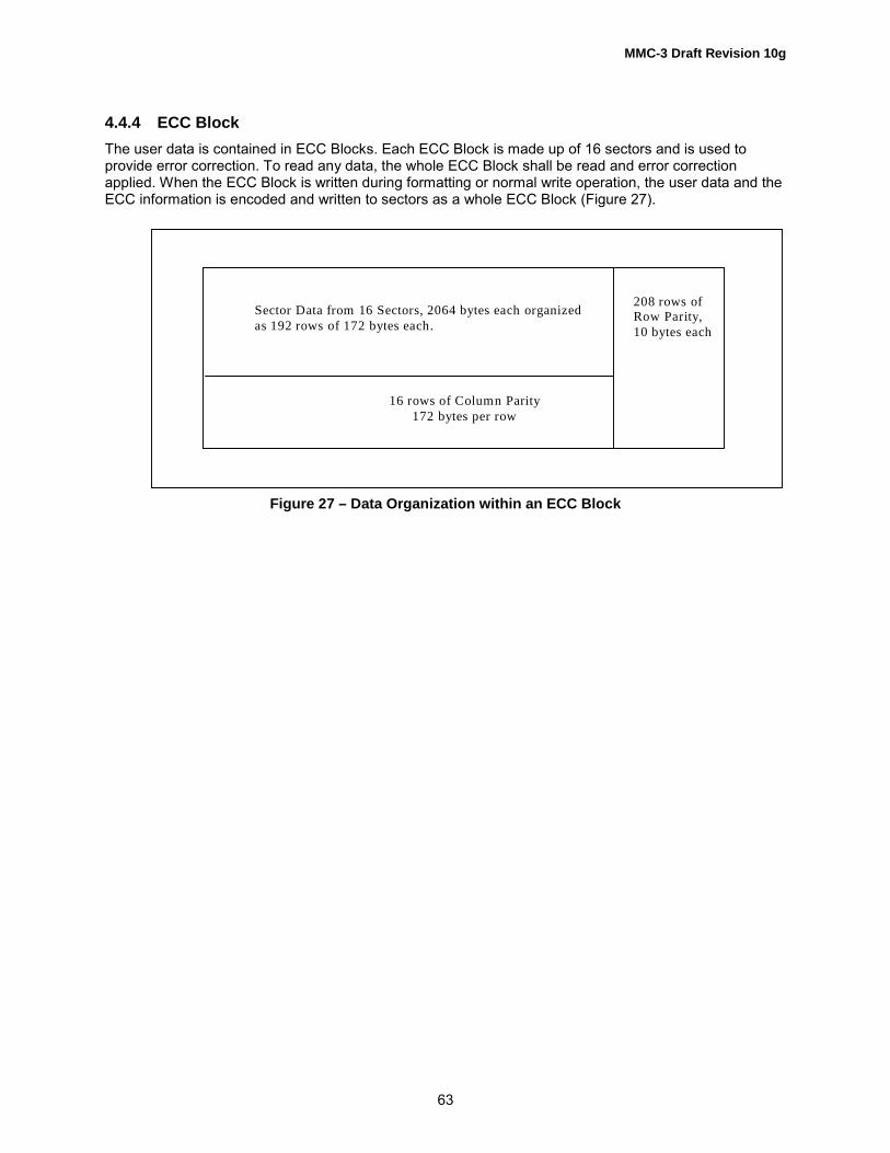
MMC-3 Draft Revision 10g
63
4.4.4 ECC BlockThe user data is contained in ECC Blocks. Each ECC Block is made up of 16 sectors and is used toprovide error correction. To read any data, the whole ECC Block shall be read and error correctionapplied. When the ECC Block is written during formatting or normal write operation, the user data and theECC information is encoded and written to sectors as a whole ECC Block (Figure 27).
Figure 27 – Data Organization within an ECC Block
Sector Data from 16 Sectors, 2064 bytes each organized as 192 rows of 172 bytes each.
208 rows of Row Parity, 10 bytes each
16 rows of Column Parity172 bytes per row

MMC-3 Draft Revision 10g
64
4.4.5 Sector Configuration
4.4.5.1 Physical SectorThe data recorded to the DVD media is in a format called �Data Unit 3,� which consists of 2 048 bytes ofUser Data, 12 bytes of Data ID and others, 4 bytes of error detection code (EDC), 302 bytes of ECC and52 bytes of SYNC. During the formation of the Data Unit 3, there are intermediate products which arecalled �Data Unit 1� and �Data Unit 2� according to the stage of signal processing as shown in Figure 29.The Data Unit 3 is identical among DVD-ROM, DVD-R/-RW, DVD-RAM, and DVD+RW. In the case ofDVD-ROM, DVD-R/-RW, and DVD+RW, only the Data Unit 3 is recorded. DVD-RAM media has otherfields in between the Data Unit 3 as shown in Figure 28.
Figure 28 – Physical sector of DVD media and DVD+RW media
Embossed FieldRecording Field
. . . . . .
Headerfield
Guard 1field
PSfield
VFO3field
DataUnit 3
PA3field
Guard 2field
Bufferfield
Mirrorfield
Gap field
128 2 10+J/16 20+K 35 3 2418 1 55 - K 25 – J/16
2 418 2 418 2 418
Data Unit 3 Data Unit 3 Data Unit 3
Physical Sector of DVD-ROM, DVD-R/-RW, and DVD+RW media
J is varied randomly from 0 to 15 to shift recording position of Data Unit 3 in a unit of 1 channel bit. K is varied randomly from 0 to 7 to shift recording position of Data Unit 3 in a unit of 1 byte.
Physical Sector of DVD-RAM media

MMC-3 Draft Revision 10g
65
Figure 29 – Formation of Data Unit 3The physical sector of DVD-RAM consists of Data Unit 3, preceding fields and succeeding fields to it andembossed fields. The Data Unit 3 is identical with that for DVD-ROM. The Header field contains fourphysical IDs. In the case of DVD-RAM, there are two sets of IDs; one that is contained in the Data Unit 1and another that is pre-recorded. Addressing of sectors for DVD-RAM only uses the physical (pre-recorded) ID. After formatting, it is possible for the ID in Data Unit 1 to contain an invalid address.
4.4.5.2 Data Unit 1
The make-up of Data Unit 1 is shown in Figure 30.
Figure 30 – Data Unit 1
D ata U nit 3
2 418
D ata U nit 2
2 366
D ata U nit 1
2 064
SY N C
52
EC C
302
U ser D ata
2 048
D ata ID and others
12
ED C
4
U ser D ata 1 6 0 bytes (D 0-D 1 5 9 )D ata ID IED C PR _M A I
4 B ytes 2 B ytes 6 B ytes
1 7 2 B ytes
U ser D ata 1 7 2 B ytes (D 1 60 -D 3 3 1)
U ser D ata 1 7 2 B ytes (D 3 32 -D 5 0 3)
U ser D ata 1 7 2 B ytes (D 1 7 0 8 -D 1 8 7 9)
U ser D ata 1 6 8 B ytes (D 1 8 8 0 -D 2 0 4 7) ED C4 B ytes
1 2 R o w s

MMC-3 Draft Revision 10g
66
4.4.5.3 Data Configuration of Data ID Field
4 BytesData ID IED
1 Byte 3 BytesSector Information Data Field Number
1 Bit 1 Bit 1 Bit 1 Bit 2 Bits 1 Bit 1 Bit
Sector Formattype
TrackingMethod
Reflectivity Reserved orRecording Type
Area Type Data Type LayerNumber
0 - CLV format1 - ZonedFormat
0 - Pit1 - Groove
0 - > 40%1 - ≤ 40%
See Table 29 00 - Data01 - Lead-in10 - Lead-out11 - Middle
See Table 28 0 - Layer 01 - Layer 1
Figure 31 – Data ID Field definition
Data Type bit definition is defined in the following table (Table 28).
Table 28 – Data Type bit definition
Media Type Data Type bit0 1
ROM Read-only data N/ARAM Embossed data Rewritable dataR Read-only data Next sector is Linking Data-RW Re-Recordable data Next sector is Linking Data+RW N/A Rewritable Data
Table 29 – Recording Type bit definition for DVD-RAM Ver.2.1 Media (1)
Area Definition
Embossed data zone ReservedRewritable data zone Lead-in area, Lead-out area Reserved
Data area 0b: General data(2)
1b: Real time data(3)
Notes:1. The definition of the bit for other than DVD-RAM Ver.2.1 Media is Reserved.2. General data: Linear replacement algorithm is applied to a Block containing the corresponding sector
if the Block is defective.3. Real-Time data: Linear replacement algorithm is not applied to a Block containing the corresponding
sector even if the Block is defective.

MMC-3 Draft Revision 10g
67
The Data Field Number consists of the PSN and other data. See Table 30.
Table 30 – Data Field Number for DVD Media
Area Media Type Description Data Field Number
Lead-in andLead-out
ROM, R,-RW, RAM,+RW
Pre-recorded information, orwritten for DVD-R/-RWmedia
PSN
Data Area ROM, R,-RW, +RW
Pre-recorded information orwritten for DVD-R/-RWMedia
PSN = (LBA + 30000h)
RAM ECC Block written by theInitiator
LBA + 31000h
ECC Block not written bythe Initiator after formatting
Any of the following three cases(1) Initialization pattern(2) Unrecorded(3) Old value of LBA + 31000h assigned beforeprevious re-formatting

MMC-3 Draft Revision 10g
68
4.4.6 Data Structure of the Disc Lead-in AreaFigure 32 shows the structure of the lead-in area for each DVD media type.
1D830h
.
DVD-RW,DVD-R for General
ver 2.0
DVD-R ver 1.0,DVD-R
for Authoringver 2.0
DVD+RW DVD-ROM DVD-RAM
.22FA0h Initial Zone
All 00h
Initial Zone
All 00h
Initial Zone
All 00h Initial Zone
All 00h*
Initial Zone
All 00h*
2A480h
Test, Guard,
ID Zones
2D600h
2E1FFh
System ReservedZone
2E200h Buffer Zone 0
All 00h
2E400h R/RW Physical format
information Zone
2F000h Reference Code Zone
(2 ECC blocks)
Reference Code Zone Reference CodeZone*
Reference CodeZone*
(1 ECC block)
2F010h
Reference Code Zone
(2 ECC blocks)
2F020h Buffer Zone 1
All 00h
Buffer Zone 1
All ooh
Buffer Zone 1
All 00h
Buffer Zone 1
All 00h*
Buffer Zone 1
All 00h*
2F200h Control Data Zone*
(192 ECC Blocks)
Control Data Zone
(192 ECC Blocks)
Control Data Zone
(192 ECC Blocks)
Control Data Zone*
(192 ECC Blocks)
Control Data Zone*
(192 ECC Blocks)
2FE00h Extra Border Zone Buffer Zone 2
All 00h
Buffer Zone 2
All 00h
Buffer Zone 2
All 00h*
Buffer Zone 2*
All 00h
LEAD
IN
AREA
30000h DATA
AREA
DATA
AREA
DATA
AREA
DATA
AREA*
Defect Controls
31000h DATA
AREA
NOTE: * = Data in these areas is embossed. For DVD-R for Authoring Ver.2.0 media, Buffer Zone 1 may containmanufacturer specific authoring Information. Otherwise, Buffer Zone 1 contains all 00h data. For DVD-R forGeneral Ver.2.0, Control Data Zone is pre-recorded or embossed Reference Code Zone contains repetitionof the Data Symbol �172� with added scrambled data Control Data Zone comprises repetition of 16 sectors(one ECC Block).
Figure 32 – Data Structure of Disc Lead-in Area

MMC-3 Draft Revision 10g
69
4.4.6.1 Control Data ZoneThe Control Data Zone contains 192 ECC Blocks. Each of the ECC Blocks (16) Sectors contains one offour distinct types of data. See Table 31 for a generic descriptor.For DVD-RW media, the Control Data Zone is embossed. Logical Unit may use RW-Physical formatinformation Zone or Extra Border Zone instead of Control Data Zone.For DVD-R for General Ver.2.0 media, the Control Data Zone is pre-recorded or embossed. And DiscManufacturing Information field contains all 00h data.
Table 31 – Control Structure of Control Data Block
SectorNumber
Description
0 Physical Format Information1 Disc Manufacturing Information2�...�
Reserved
1415
4.4.6.2 Control Zone Sector Descriptions
Table 32 shows the format of the Physical Format Information descriptor.
Table 32 – Common Part of Physical Format Information
BitByte
7 6 5 4 3 2 1 0
0 Book Type Part Version1 Disc Size Maximum Rate2 Reserved Number of Layers Track
PathLayer Type
3 Linear Density Track Density45………
Data Area Allocation
1516 BCA Flag
(1)Reserved
17-2047 Medium Unique Data
Note: For DVD-RW/DVD-R for General Ver.2.0 media, BCA Flag is defined as NBCA Flag.

MMC-3 Draft Revision 10g
70
The Book Type field is described in Table 33.
Table 33 – Book Type Field
Book Type Value Definition
0 DVD-ROM1 DVD-RAM2 DVD-R3 DVD-RW9 DVD+RW
Others Reserved
Table 34, Table 35, Table 36, Table 37, and Table 38 define the format unique descriptors for each mediatype.
Table 34 – DVD-ROM Unique Part of Physical Format Information
BitByte
7 6 5 4 3 2 1 0
32-2047 Reserved
Table 35 – DVD-R Ver 1.0/-R for Authoring Ver.2.0 Unique Part of Physical Format Information
BitByte
7 6 5 4 3 2 1 0
32~35 Start PSN of the current Border-out36~39 Start PSN of the next Border-in
40-2047 Reserved
Table 36 – DVD-RW/-R for General Ver.2.0 Unique Part of Physical Format Information
BitByte
7 6 5 4 3 2 1 0
32~35 Start PSN of the Extra Border Zone (= 02FE10h)36~39 Start PSN of Physical format information blocks in Extra Border Zone (= 02FFA0h)
40-2047 Reserved

MMC-3 Draft Revision 10g
71
Table 37 – DVD-RAM (Ver.1.0) Unique Part of Physical Format Information
BitByte
7 6 5 4 3 2 1 0
32 Disc Type Identification33-47 Reserved
48 Velocity 149-65 Write conditions at Velocity 1
66-479 Reserved for write conditions at velocity of Velocity 2 to Velocity 24480-2047 Reserved
Table 38 – DVD-RAM (Ver. 2.1) Unique Part of Physical Format Information
BitByte
7 6 5 4 3 2 1 0
32 Disc Type Identification33-499 Reserved
500 Velocity501-548 Write conditions at Velocity549-596 Disc Manufacturer�s name597-612 Disc Manufacturer�s supplementary information
613-2047 Reserved

MMC-3 Draft Revision 10g
72
Table 39 – DVD+RW Unique Part of Physical Format
BitByte
7 6 5 4 3 2 1 0
32 Recording Velocity33 Maximum read power at reference velocity34 PIND at reference velocity35 ρ at reference velocity36 ε1 at reference velocity37 ε2 at reference velocity38 γtarget at reference velocity39 Maximum read power at maximum velocity40 PIND at maximum velocity41 ρ at maximum velocity42 ε1 at maximum velocity43 ε2 at maximum velocity44 γtarget at maximum velocity45 Maximum read power at intermediate velocity46 PIND at intermediate velocity47 ρ at intermediate velocity48 ε1 at intermediate velocity49 ε2 at intermediate velocity50 γtarget at intermediate velocity51 Ttop first pulse duration52 Tmp multi pulse duration53 dTtop first pulse lead time54 dTera erase lead time at reference velocity55 dTera erase lead time at intermediate velocity56 dTera erase lead time at intermediate velocity
57-2047 Reserved

MMC-3 Draft Revision 10g
73
4.4.6.3 DVD-R/-RW Physical format information ZoneThe R/RW-Physical format information Zone is defined only for DVD-RW and DVD-R for General Ver.2.0media. The R/RW-Physical format information Zone contains 192 ECC blocks. Each DVD-R/-RWPhysical format information consists of 16 sectors and is repeated 192 times.The structure of R/RW-Physical format information is shown in Table 40.
Table 40 – DVD-R/-RW Physical Format Information Zone
SectorNumber
Description
0 Reserved1 Manufacturing Information2 Physical Format Information3 Reserved:
15
The contents of the Physical Format Information in DVD-R/-RW Physical format information Zone is sameas the contents of Physical Format Information in Control Data Zone except Data Area Allocation fieldand unique part of Physical Format Information (byte 32 - byte 2047).The definition of the Data Area Allocation field in DVD-R/-RW Physical format information is shown inTable 41.
Table 41 – Data Area Allocation Field in DVD-R/-RW Physical Format Information
Byte Disc at Once Incremental Write/Restricted Overwrite4 00h 00h5 Starting PSN of Data Area (030000h) Starting PSN of Data Area (030000h)678 00h 00h9 End PSN of Data area Last Recorded Sector Number of the last Track in
the Session (1)
101112 00h 00h13 000000h 000000h1415
Note: When the Lead-in or Border-in is recorded in the Restricted Overwrite mode, and when the lastsession is in an Intermediate state, this field shall be set to 30000h
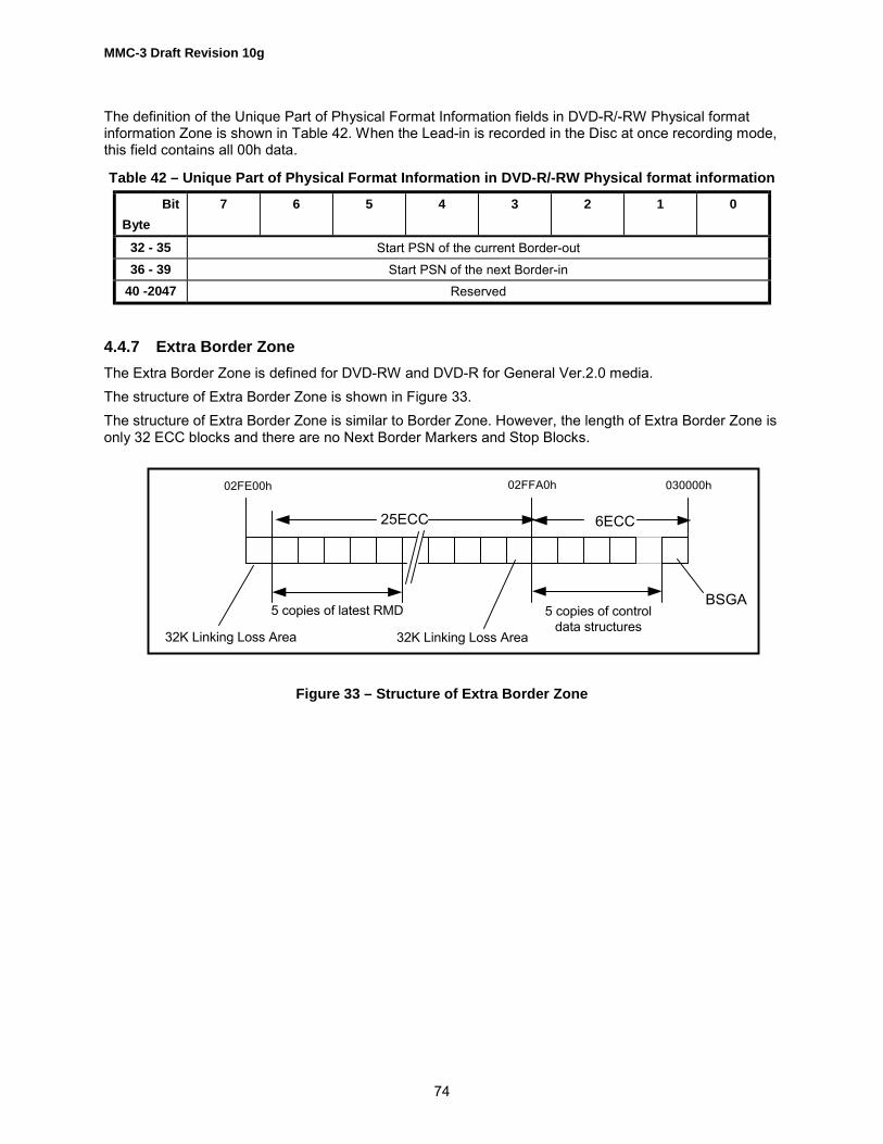
MMC-3 Draft Revision 10g
74
The definition of the Unique Part of Physical Format Information fields in DVD-R/-RW Physical formatinformation Zone is shown in Table 42. When the Lead-in is recorded in the Disc at once recording mode,this field contains all 00h data.
Table 42 – Unique Part of Physical Format Information in DVD-R/-RW Physical format information
BitByte
7 6 5 4 3 2 1 0
32 - 35 Start PSN of the current Border-out36 - 39 Start PSN of the next Border-in
40 -2047 Reserved
4.4.7 Extra Border ZoneThe Extra Border Zone is defined for DVD-RW and DVD-R for General Ver.2.0 media.The structure of Extra Border Zone is shown in Figure 33.The structure of Extra Border Zone is similar to Border Zone. However, the length of Extra Border Zone isonly 32 ECC blocks and there are no Next Border Markers and Stop Blocks.
Figure 33 – Structure of Extra Border Zone
5 copies of latest RMD 5 copies of controldata structures
32K Linking Loss Area
02FE00h 02FFA0h 030000h
25ECC 6ECC
32K Linking Loss Area
BSGA

MMC-3 Draft Revision 10g
75
Table 43 describes the contents of the Data Area Allocation field.
Table 43 – Data Area Allocation Definition
Byte SingleLayer/
ParallelTrack PathDVD-ROM
OppositeTrack PathDVD-ROM
DVD-RVer.1.0
DVD-R forAuthoring
Ver.2.0(DAO)
DVD-RVer.1.0
Incremental
DVD-RW/DVD-R forGeneralVer.2.0
DVD-RAM DVD+RW
4 00h 00h 00h 00h 00h 00h 00567
StartingPSN of DataArea(030000h)
StartingPSN of DataArea(030000h)
StartingPSN of DataArea(030000h)
Starting PSNof Data Area(030000h)
StartingPSN of DataArea(030000h)
StartingPSN of DataArea(031000h)
Starting PSN ofData Area(030000h)
8 00h 00h 00h 00h 00h 00h 00h9
1011
End PSN ofData Area
End PSN ofData Area
End PSN ofData Area
Last RecordedSector Numberof the last Trackin the Session
Lastaddress ofDataRecordablearea(1)
End PSN ofData Area
If CDZ PSN ≤2F0FFh, then thisvalue shall be thePSN of lastrecorded sector inDZ. Otherwise, thisvalue may be eitherthe PSN of lastrecorded sector inDZ, or the lastpossible PSN in theDZ.
12 00h 00h 00h 00h 00h 00h 00h131415
000000h End PSN inLayer 0
000000h 000000h 000000h 000000h 000000h
Note: For DVD-R for General Ver.2.0 media, this field is defined as �Outer limit of Data Recordable area�.
For DVD-RAM, the end PSN is the PSN for the last spare sector of the last zone. It should not be used forcounting user capacity.For DVD+RW, the end PSN should not be used for counting user capacity.
4.4.8 DVD Ready Condition/Not Ready ConditionThe Ready Condition occurs after a disc is inserted and the Logical Unit has performed its initializationtasks. These may include reading the Lead-in information from the media. This �Ready� is different fromand should not be confused with the ATA Ready Status. A CHECK CONDITION status shall be returnedfor the Not Ready Condition only for commands that require or imply a disc access.A Not Ready Condition may occur for the following reasons:a. There is no disc mounted.b. The Logical Unit is unable to load or unload the disc.c. The Logical Unit is performing an extended operation as the result of an Immediate Mode commandsuch as FORMAT UNIT or BLANK.The Logical Unit shall spin up and make the disc ready for media accesses when a new disc is detected.
MMC-3 Draft Revision 10g
76
Any media access that occurs when the Logical Unit is not spinning shall spin the media up and notgenerate an error. Any media access that is requested while a deferred operation is in progress (i.e.writing from a write cache) shall not generate an error. Any media access that is requested while theLogical Unit is processing an Immediate command, e.g. BLANK or FORMAT UNIT with the Immediate bitset, may result in a Not Ready Condition.Note: Accesses to the media can be satisfied from the Logical Unit�s cache and may not require themedia to be spinning.
4.4.9 DVD Content ProtectionThe DVD Content Protection is made up of two basic concepts. The first is to scramble the content of thedata such that unscrambling is required in order to make the content usable. The capability to unscramblethe content is provided only under conditions that require products that follow rules governing thecopying, playback, and output of the content. The second basic concept is to use an �Authentication�process to exchange protected information (such as cryptographic Keys) required for the unscrambleoperation. This process ensures the integrity of such information during transfer from the Logical Unit tothe Initiator.
4.4.9.1 Content Protection for Read Only DVDThe DVD-Video Content Scrambling System (CSS) is used to protect DVD-Video content on Read OnlyDiscs. Content Protection for Prerecorded Media (CPPM) is used to protect DVD-Audio content on ReadOnly Discs. For discs containing CSS or CPPM protected content (or both), the same authenticationprocess is used. Thus, Logical Units that support CSS authentication also support CPPM withoutmodification. Any read by the Host to a disc that contains CSS scrambled content and a sector with aTitle Key present, when the Authentication Success Flag (ASF) is set to zero shall be terminated with aCHECK CONDITION status, 5/6F/03 READ OF SCRAMBLED SECTOR WITHOUT AUTHENTICATION.For more information on the Authentication process, see Figure 33. For more information on theAuthentication Success Flag, see Figure 34.Note: Although CSS and CPPM use the same authentication process for transferring the Disc Key orAlbum ID, CPPM protected sectors do not contain a Title Key. Thus for CPPM, the TITLE KEY Format isnot used, and the Authentication Success Flag is not relevant.For CSS protected content (DVD-Video) only, playback of the content is limited to specific regions of theworld, as described in 4.4.9.4.
4.4.9.2 Content Protection for recordable and rewritable DVDContent Protection for Recordable Media (CPRM) is used to protect audio and video content onrecordable and rewritable DVD discs. The interface between the Initiator and Logical Unit for CPRM issimilar to that for CPPM, with the following differences:
• CPRM uses a �MEDIA IDENTIFIER� to bind protected content to the disc on which it is recorded.Before encrypting or decrypting such content the Initiator reads the MEDIA IDENTIFIER value usingthe READ DVD STRUCTURE command with Format code 06h.
• The CPRM "MEDIA KEY BLOCK" is located in the Lead-in area, and is read by the Initiator using theREAD DVD STRUCTURE command with Format code 07h.
The CPRM �MEDIA IDENTIFIER� and �MEDIA KEY BLOCK� are protected during transfer to the Initiatorusing the same Authentication process used for CSS and CPPM, with the addition of a MessageAuthentication Code (MAC) algorithm described in the CPRM specification. For more information on theauthentication process, see Figure 35.

MMC-3 Draft Revision 10g
77
4.4.9.2.1 Authentication Process
Figure 34 – Device Key Exchange and Authentication State Diagram
Figure 35 – Authentication Flag Sequence
Begin Sequence
Hold 1
Initial State
Wait for Initiator AuthenticationBus KeyEstablished
Bus Key Used toobfuscate other key
(Authentication Completed)
Region Code Error(s) fromREPORT KEY (TITLE KEY)Command
Error, Authentication Failed
Power-on reset,Hard ResetEject
No GrantsAvailable
REPORT KEY (Request AGID for CSS/CPPM or CPRM)
SEND KEY (Challenge Key)
REPORT KEY (Key 1)
REPORT KEY (Challenge Key)
SEND KEY (Key 2)
Note: Initiator must reset a non-responding authentication process in the Logical Unit by invalidating the corresponding AGID. The Initiator may detect lost grants by refusal of the Start Authentication Process operation This diagram assumes the appropriate CSS/CPPM/CPRM media is loaded.
Power-On Reset,Hard Reset
Disc includes scrambled CSS/CPPM protectedcontent and �DISC KEY� is exchanged.
(READ DVD STRUCTURE with Format = 02h)
Regionalization Error to REPORT KEY (Title Key) (Only for CSS)
Power-On Reset,Hard Reset, Eject
AuthenticationNot Valid
(ASF = 0)
AuthenticationIs Valid
ASF = Authentication Success Flag

MMC-3 Draft Revision 10g
78
4.4.9.3 Region Playback Control (RPC)The copy management capability used for Copy Protected DVD-ROM Media limits the playback ofcontent to specific regions of the world. This capability is called Region Playback Control (RPC) orRegionalization.
4.4.9.4 Playback limitations by World RegionThe use of Regionalization is limited to Discs that employ CSS. There are two places that contain regioninformation, one in the Logical Unit and another for each media that contains CSS Scrambled Title(s).When the region in the Logical Unit and that of the CSS Title are different, the system shall prevent theplayback of that title (movie).When a REPORT KEY command is received, by a Logical Unit, in the Bus Key Established state, (seeFigure 34), with a Format Code of 04h (Title Key), and the region code of the current media is notplayable in the current region set in the Logical Unit, the command shall be terminated with CHECKCONDITION status and SK/ASC/ASCQ shall be set to ILLEGAL REQUEST/MEDIA REGION CODE ISMISMATCHED TO LOGICAL UNIT REGION. A regionalized CSS media shall be deemed not playable ifthe region of the Logical Unit is not set.If the Region Code Mismatch error is generated, the Authentication Success Flag (ASF) shall be clearedto zero.The Logical Unit reports the current RPC State when processing the REPORT KEY command withFormat Code 08h.
4.4.9.5 Region Code SettingTwo methods have been defined for setting the region code in the DVD Logical Unit. Each method hasthe same end result, specifying which region shall be used to determine if it is allowable to play a disc thathas a region code included within the information on the disc in this Logical Unit.The Logical Unit has the following four Region States according to the Logical Unit Region setting (seeFigure 36):1. NONE state - The Logical Unit Region has not been set. The Initiator shall set the initial Logical UnitRegion value in the Logical Unit. The region setting counter shall be set to 5. The Logical Unit shallrespond to the REPORT KEY command, Key Format 01000b, with successful command completion anda Region Mask value of FFh.2. SET state - The Logical Unit Region has been set and the change of the Region is acceptable. Theregion setting counter shall initially be 4, and decrement to 2.3. LAST CHANCE state - The Logical Unit Region has been set and the change of the Region isacceptable. In order to change the Logical Unit Region using a command method, an inserted disc shallhave the same single region with the requested Region. The region setting counter shall be 1.4. PERMANENT state - The Logical Unit Region has been set and the change of the Region is notacceptable. The region setting counter shall be 0. However, the Logical Unit Region can be re-initializedby the vendor to become the NONE state.
4.4.9.6 Initial SettingIn the NONE state, the Logical Unit Region is not set and the Initiator shall set the initial Logical UnitRegion value in the Logical Unit. The region setting counter shall be set to 5. The Logical Unit shallrespond to the REPORT KEY command, Key Format 01000b, with successful command completion anda Region Mask value of FFh.

MMC-3 Draft Revision 10g
79
The Initiator shall set a preferable region, the value of which is specified in the Preferred Logical UnitRegion Code field of the SEND KEY command with Key Format = 000110b. On execution of thiscommand, the Logical Unit ignores the region code of the inserted medium.After the successful execution of setting the Logical Unit Region, the Logical Unit shall enter the SETstate. The region setting counter shall be decremented to 4.
4.4.9.7 Changing of the Logical Unit RegionIn the SET state, the Logical Unit Region has been set and may be changed by one of the two methodsspecified. After the successful execution of changing the Logical Unit Region, the region setting countershall be decremented. When the region setting counter is 2 and a successful execution of changing of theLogical Unit Region, the Logical Unit shall enter into the LAST CHANCE state.In the LAST CHANCE state, the Logical Unit Region may be changed by one of the two methodsspecified. See 4.4.9.7.1, and 4.4.9.7.2. When using the command method with a disc, the inserted discshall have the same single Region Code value as the Preferred Logical Unit Region Code specified in theSEND KEY command. After the successful execution of the Logical Unit Region change, the regionsetting counter shall be zero and the Logical Unit shall enter into the PERMANENT state.In the PERMANENT state, the user cannot change the Logical Unit Region.
4.4.9.7.1 Changing the Logical Unit Region with a CSS enabled Disc
To set the Logical Unit Region, the procedure shall be executed as follows;1. Insert a disc having the requested Region,2. Issue a SEND KEY command with the Key Format = 000110b. The requested Region Code value shallbe specified in the Preferred Logical Unit Region Code field.When the Logical Unit receives the SEND KEY command correctly, the Logical Unit Region is changed tothe requested region. If the disc does not have the same region code value as the Preferred Logical UnitRegion Code specified in the SEND KEY command, then the command shall be terminated with CHECKCONDITION status and SK/ASC/ASCQ values are set to ILLEGAL REQUEST/MEDIA REGION CODE ISMISMATCHED TO LOGICAL UNIT REGION.
4.4.9.7.2 Setting Disc method for changing the Logical Unit RegionInserting a special disc that contains a specific region code may set the Logical Unit Region. This specialdisc does not require any command intervention.
4.4.9.8 Limits on Logical Unit Region ChangesAny of the methods defined in this specification may be used up to five times to change a Logical Unit�sregion. If the new region is the same as the old region, the region setting process shall be treated as if ithad not occurred.If an attempt by the user is made to change the Logical Unit Region more than five times, the SEND KEYcommand shall terminate with CHECK CONDITION status, sense key set to ILLEGAL REQUEST andASC set to LOGICAL UNIT REGION MUST BE PERMANENT/REGION RESET COUNT ERROR.For more information on the region code setting process, see Figure 36.

MMC-3 Draft Revision 10g
80
Figure 36 – Region State Diagram
Manufacturer or Vendor NONE State
Initial“No Logical Unit Region”
n = 5
SEND KEY Command with a requestedregion is issued, or Setting Disc is inserted
The value of n shall be decremented
SET State
The Logical UnitRegion is set
n = 4 to 2
SEND KEY Command with requestedregion that would allow playback withthe inserted disc is issued, or SettingDisc is inserted. (2 times)
The value of n shall be decrementedWhen n becomes 1
LAST CHANCE state
The Logical UnitRegion is set
n = 1PERM state
The Logical UnitRegion is set
n = 0
SEND KEY Command with requested region thatmatches a single region disc that is inserted isissued, or Setting Disc is inserted.
The value of n shall be 0
n: Count down counter value that indicates the number of times that the Logical Unit Region is allowed to change.
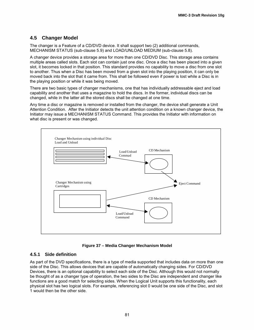
MMC-3 Draft Revision 10g
81
4.5 Changer ModelThe changer is a Feature of a CD/DVD device. It shall support two (2) additional commands,MECHANISM STATUS (sub-clause 5.9) and LOAD/UNLOAD MEDIUM (sub-clause 5.8).A changer device provides a storage area for more than one CD/DVD Disc. This storage area containsmultiple areas called slots. Each slot can contain just one disc. Once a disc has been placed into a givenslot, it becomes locked in that position. This standard provides no capability to move a disc from one slotto another. Thus when a Disc has been moved from a given slot into the playing position, it can only bemoved back into the slot that it came from. This shall be followed even if power is lost while a Disc is inthe playing position or while it was being moved.There are two basic types of changer mechanisms, one that has individually addressable eject and loadcapability and another that uses a magazine to hold the discs. In the former, individual discs can bechanged, while in the latter all the stored discs shall be changed at one time.Any time a disc or magazine is removed or installed from the changer, the device shall generate a UnitAttention Condition. After the Initiator detects the unit attention condition on a known changer device, theInitiator may issue a MECHANISM STATUS Command. This provides the Initiator with information onwhat disc is present or was changed.
Figure 37 – Media Changer Mechanism Model
4.5.1 Side definitionAs part of the DVD specifications, there is a type of media supported that includes data on more than oneside of the Disc. This allows devices that are capable of automatically changing sides. For CD/DVDDevices, there is an optional capability to select each side of the Disc. Although this would not normallybe thought of as a changer type of operation, the two sides to the Disc are independent and changer likefunctions are a good match for selecting sides. When the Logical Unit supports this functionality, eachphysical slot has two logical slots. For example, referencing slot 0 would be one side of the Disc, and slot1 would then be the other side.
Changer Mechanism using individual Disc Load and Unload
Changer Mechanism using Cartridges
Load/Unload Commad
Load/Unload Command
CD Mechanism
CD Mechanism
Eject Command

MMC-3 Draft Revision 10g
82
There are two fundamental techniques used to select each side of DVD media. The first is the mostspace efficient. It simply moved the Pick Up (laser unit used to read the disc) to the other side. This doesadd complexity to the laser mechanism to be able to position it on either the bottom or top of the media.The second approach is to flip the media over.For a Logical Unit that supports changing sides (see Table 361), the number of Slots reported shall beeven, and every other slot shall be an alternating side.
4.5.1.1 Side Changing Only Logical UnitA Logical Unit that is capable of changing the side of the Disc, but does not have separate Slots from theplaying position, reports that it has a Mechanism type that is not a changer, but also reports Side ChangeCapable. This style of Logical Unit still uses the LOAD/UNLOAD MEDIUM command to change thecurrently selected side. The Logical Unit shall report two slots available.When the Logical Unit can only change sides, and not discs, it does not perform any action. This appearsto the Initiator as a Logical Unit with a Delayed Load type of operation.A DVD Logical Unit that supports changing sides is not able to report if there is actually data on bothsides until each side has been read.
4.5.1.2 Attention Conditions for Sided DiscsDevices that support changing sides shall set SK/ASC/ASCQ to UNIT ATTENTION/NOT READY TOREADY CHANGE - MEDIUM MAY HAVE CHANGED (06h/28h/00h) for changes that involve discloading.
4.5.1.2.1 Error Conditions for Sided DiscsDevices that support changing disc sides shall set SK/ASC/ASCQ to NOT READY, NO REFERENCEPOSITION FOUND (02h/06h/00h) to report when the currently selected side does not contain valid data.

MMC-3 Draft Revision 10g
83
4.5.1.3 InitializationThe Changer shall perform its initialization routine at power on or hard reset.�Initializing Changer� is a process that refers to gathering the information that is necessary to respond tothe MECHANISM STATUS command. If a changer is in the process of initializing when it receives aMECHANISM STATUS command, it responds immediately and provides no slot table information (onlythe Header).
Figure 38 – Changer State Diagram
N oC artridg e
Present
Pow er O nInit ia liza tion
R eset a ndL oad D isc 0
PO R
R ead T O C &M ak e D isc
R ead y to u se
C artridg e L oad ed
R eset(S ta te is In itia liza t ing)
“U N IT A T T E N T IO N ” I f a D isc is ad d ed or rem oved
D isc 0 is pre sen t
M ov eSpecified S lot
in to th eP lay P osit ion
M ov ecu rrent D iscfrom P lay ing
Posi tion toS to rag e
W ait forD isc C ha nge
or a L oa dC om m an d
M ov e D iscto externa l
Posi tion
L oa d C om plete
L oa d C om m a nd
L oad C om m a nd
“U N IT A T T E N T IO N ” I f a D isc is ad d ed or r em o v ed
U nload (Sta te is U nload in Pro gress
L oa d (Sta te is L oad in P rogre ss
D isc 0 n ot present
D isc 0 is pre sent
E ject C a r tridg e C om m a nd
G en erate an “ U N IT A T T E N T IO N ”for th e r ea dy to not read y
Idle bu t n o D isc, D ev ice w ill b e N O T R E A D Y bu t the C ha ng erS tate is “R ea dy”
U nloa d C om m a nd
U nloa d C om plete
E ject Sing le D isc C om m a nd

MMC-3 Draft Revision 10g
84
4.5.2 Changer AddressingSeveral Changer specific commands use addresses called �Slots.�If any commands related to Changer operations are implemented, then all the Changer commands shallbe implemented. To determine if a Logical Unit is a changer type device, the Embedded Changer Featureshall be reported in response to an appropriate GET CONFIGURATION command.There is a legacy method to determine if a Logical Unit is a changer type device. The Loading MechanismType field in the CD/DVD Capabilities & Mechanical Status Mode Page contains one of the two changertype codes (See Table 148) for individual disc or magazine implementations.
4.5.3 Automatic Load and Unload OperationsAfter initialization is complete the changer shall have Disc 0 loaded into the play position. This enablesdrivers that are not changer aware to work with a changer device as if it were a normal single CD/DVDdevice. This also ensures compatibility with a Bootable CD/DVD. In support of this goal the changer shallalso load and unload (Eject) default Disc 0 if the changer supports loading and unloading (Ejecting)individual Discs unless otherwise commanded by the use of one of the changer specific Load/Unloadcommands.When a LOAD/UNLOAD command is received and a Disc is present in the Playing position, it shall beunloaded automatically before the specified Load operation is performed.
4.5.4 Delayed Disc load operationCD/DVD Changer Devices may either move a disc into the playing position immediately upon receipt of aLOAD command, or delay the loading of the disc until a media access command is received. It isrecommended that the device not load discs into the playing position until data from a disc that is notcached is requested from the Initiator.Note that Initiator drivers should expect to encounter load mechanism delays on media accesses inaddition to the spin up and seek delays normally introduced with these commands.If the device supports delayed loading and the selected disc is not in the play position, then thecommands listed in Table 44 shall move the selected disc into the play position when data that has notbeen cached has been requested by the Initiator.
Table 44 – Commands that may not cause delayed loads to occur
Commands
Play Audio (10)Play Audio MSFRead (10)Read (12)Read CDRead CD MSFRead CD-ROM CapacityRead Sub-channelRead TOCScan
If the device supports delayed loading and the selected disc is not in the play position, then the followingcommands shall load the selected disc into the play position before execution of the command (See
Table 45).
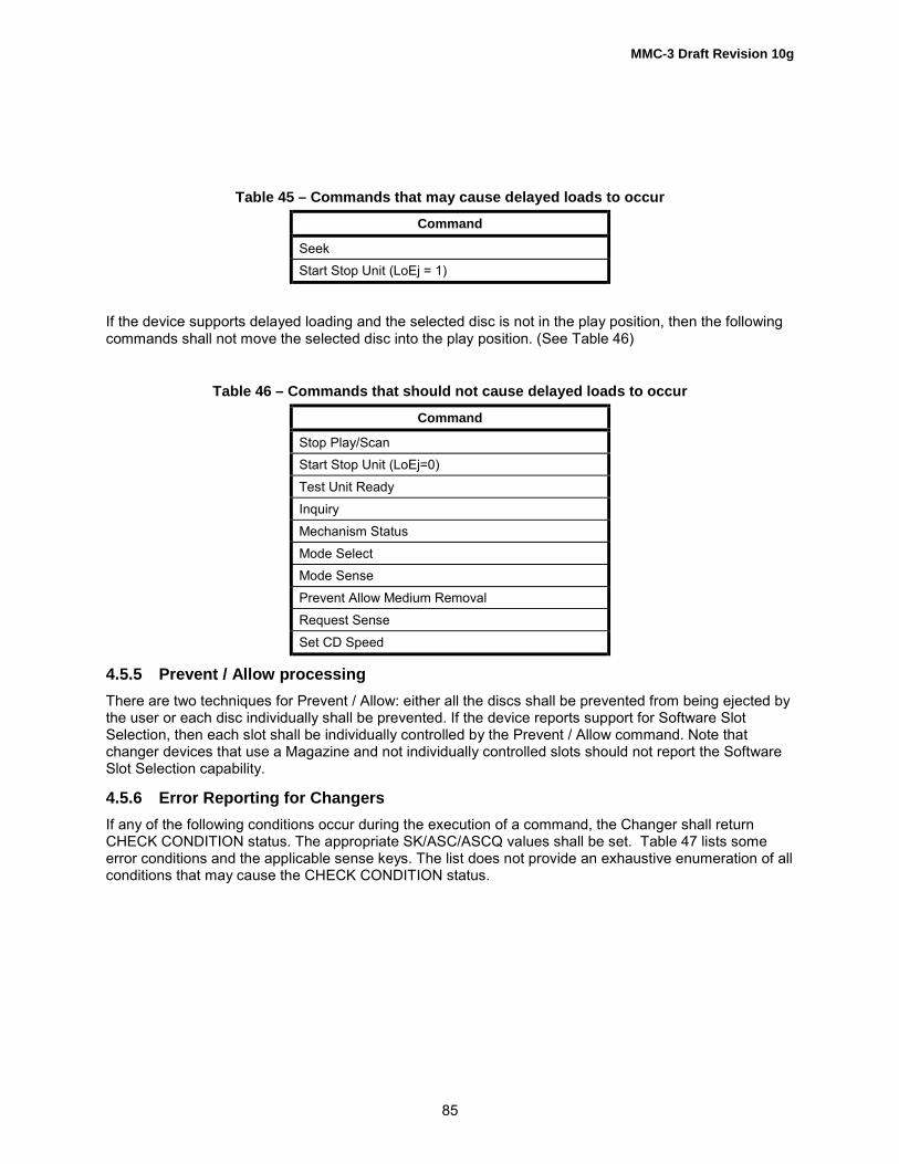
MMC-3 Draft Revision 10g
85
Table 45 – Commands that may cause delayed loads to occur
Command
SeekStart Stop Unit (LoEj = 1)
If the device supports delayed loading and the selected disc is not in the play position, then the followingcommands shall not move the selected disc into the play position. (See Table 46)
Table 46 – Commands that should not cause delayed loads to occur
Command
Stop Play/ScanStart Stop Unit (LoEj=0)Test Unit ReadyInquiryMechanism StatusMode SelectMode SensePrevent Allow Medium RemovalRequest SenseSet CD Speed
4.5.5 Prevent / Allow processingThere are two techniques for Prevent / Allow: either all the discs shall be prevented from being ejected bythe user or each disc individually shall be prevented. If the device reports support for Software SlotSelection, then each slot shall be individually controlled by the Prevent / Allow command. Note thatchanger devices that use a Magazine and not individually controlled slots should not report the SoftwareSlot Selection capability.
4.5.6 Error Reporting for ChangersIf any of the following conditions occur during the execution of a command, the Changer shall returnCHECK CONDITION status. The appropriate SK/ASC/ASCQ values shall be set. Table 47 lists someerror conditions and the applicable sense keys. The list does not provide an exhaustive enumeration of allconditions that may cause the CHECK CONDITION status.

MMC-3 Draft Revision 10g
86
Table 47 – Error Conditions and Sense Keys for Changer Mechanisms
Condition Sense Key
Invalid Slot Number ILLEGAL REQUESTUnsupported option requested ILLEGAL REQUESTLoad or Unload to invalid slot or no Disc in sourcelocation
ILLEGAL REQUEST
Device Reset or medium change since last command UNIT ATTENTIONSelf diagnostic failed HARDWARE ERROR
In the case of an invalid Slot number, the sense data information field shall be set to the Slot number ofthe first invalid address.Attempts to eject a Disc if the changer type is magazine and there is a Disc in the playing position shallbe rejected with a CHECK CONDITION status and SK/ASC/ASCQ values shall be set to ILLEGALREQUEST/MECHANICAL POSITIONING OR CHANGER ERROR.
4.6 Real-Time Stream Recording/Playback ModelThe Real-Time Stream recording/playback is one of the most important applications for recordable opticaldiscs. It is also expected as a bridge between PC peripherals and consumer devices such as DVDPlayer. However, optical disc drives, especially consumer players, have low access performancecomparing with hard drives from the viewpoint of data rate or seek delay. In addition, dispersion ofrecorded Streaming data on recordable optical discs may further degrade the performance leading to thepoor quality of data playback. In order to address the issue, streaming data should be arrangedcontinuously on a disc in order to guarantee the minimum bit rate for Real-Time Streamrecording/playback.One of factors to make dispersion of Streaming data may be attributed to defects. When a recordableoptical disc is handled without a cartridge on consumer players, more defects due to contamination maybe encountered during stream recording than used with a cartridge only. On the other hand, because ofReal-Time requirement, a Logical Unit may not be allowed as much time and efforts to overcome defectsencountered during Stream recording as it has during conventional data recording. The Real-TimeStream recording/playback model specifies new methods to handle defective sectors on a recordableoptical disc.
4.6.1 Stream recording operationA defect management scheme like Linear Replacement Algorithm is applied when the Logical Unitencounters such a defective sector during the conventional WRITE operation. This is one of the solutionto make the disc defect free, and it is applied to many optical discs.But for Stream recording/playback application, such a defect management makes the access speed bespoiled for Real-Time operation, because the alternative good block locates physically away from thedefective one. If this scheme is applied to Stream recording system, the system is required to haveenough buffer memory to maintain the recording transfer rate. The playback picture may be jerky if a longdistance seek operation is required to read the alternative block in the Spare Area during playing back aStreaming data from the media.To solve this problem, the Logical Unit commanded to write data using Stream recording shall not replacea defective block with the other block even if the Logical Unit encounters a defective block during Streamrecording operation.

MMC-3 Draft Revision 10g
87
Figure 39 – Example of Data Allocation in case of Linear Replacement
The Logical Unit that returns Real-Time Streaming Feature with Version field of 1 and SW bit of 1 shallsupports the following functions.An example of data allocation on a disc is shown in Figure 40. When the Stream recording operation isexecuted the Logical Unit shall continue recording without reporting error even if a defective block isfound on the Stream recording operation. The Streaming data recorded to the defective block may not beread correctly.The Initiator shall use WRITE (12) command with Streaming bit set to one to execute the Streamrecording operation. The Logical Unit shall not execute Linear Replacement operation for defective block.The Logical Unit�s performance shall be at least 1x speed even if this prevents the Logical Unit from retryor verify operation.The Logical Unit shall not report CHECK CONDITION status except fatal error, even if a defective block isfound on Stream recording operation. The Logical Unit returns a fatal error when the Stream recordingoperation can not be continued because of critical error such as hardware error.
Figure 40 – An example of data allocation on the Stream recording operation
4.6.2 Stream playback operationUsing Real Time Stream playback operation may result in erroneous data. If the data is not correctable,the Logical Unit on conventional READ operation performs error recovery operations. In case of Streamplayback operation, the highest priority should be given to continuity of data.In order to distinguish the data attribute to be read, Streaming data or other normal data, Streaming bit isdefined to the READ (12) command. If the Logical Unit receives the READ (12) command with Streamingbit set to one, the data should be read out continuously without reporting uncorrectable read error, even iferroneous blocks are detected. The Logical Unit shall transfer the required size of data on the erroneousblock without reporting error, though the transferred data may contain error. Read Ahead operationshould be applied on Stream playback operation in order to secure continuity.
Write Write
Streaming datato be recorded
Data allocationon a disc
Spare Area
A defective block is replaced by a good block in the Spare Area
Defect Defect
Write Write
Streaming datato be recorded
Data allocationon the media
Recording operation is continuedeven if a defective block is found

MMC-3 Draft Revision 10g
88
Note: The cached data that contains an erroneous portion shall not be returned by the READ (12)command when the Streaming bit cleared. In such cases, cached data in a buffer memory is discardedand attempts to read with the conventional READ operation.
4.6.3 Error Handling on Stream recording/playback operationAn erroneous block encountered on Stream recording/playback operation should be handled accordingTable 48. The defective block may be registered in defect list but the linear replacement algorithm shallnot be applied on Stream recording/playback operation.
Table 48 – Error Handling on Stream recording/playback operation
Sector Status Command Description
Good block Read No ErrorWrite No ErrorRead with Stream=1 No ErrorWrite with Stream=1 No Error
Defective block registered indefect list and replaced
Read No Error
Write No ErrorRead with Stream=1 No Error (Defect list is ignored, Null (00h) data shall be returned for Blocks
listed in a defect list) (1)
Write with Stream=1 Ignore defect list and keep recording (The data written on thedefective block is not guaranteed)
Defective block registered indefect list, but not replacedor defective block withRecording Type bit set to 1
Read No Error(2) (NULL (00h)or partially corrected data may be returned)(3)
Write No Error (The defective block should be replaced and the datashould be written to an alternative block)
Read with Stream=1 No Error (Erroneous data may be returned)Write with Stream=1 No Error (The data should be written to the defective block without
error reporting, and the defective block should still be registered indefect list)(4)
Defective block which is notregistered in defect list
Read Report Error (Erroneous data shall not be returned)
Write No Error (The defective block should be replaced and the datashould be written to an alternative block)
Read with Stream=1 No Error (Erroneous data may be returned)Write with Stream=1 No Error (The data should be written to the defective block without
error reporting, and the defective block should be registered in defectlist)(4)
Notes:(1) Legacy Logical Unit that may not comply with this specification may return erroneous data and continue reading(2) In response to the VERIFY command, the Logical Unit shall report an error.(3) This is defined to be able to playback on a legacy system that uses the conventional READ command.(4) The defective block should be registered in defect list, but linear replacement shall not be applied.

MMC-3 Draft Revision 10g
89
5 Commands for Multi-Media Devices
5.1 OverviewSome commands that may be implemented are not described in this standard, but can be found in otherSCSI standards. For a complete description of these commands, SCSI Primary Commands, SCSI BlockCommands, and others should be referenced.The commands described in this clause are defined uniquely for Multi-Media Logical Units or have aunique behavior when executed by a Multi-Media Logical Unit.
Table 49 – Commands for Multi-Media Logical Units
Command Name Op Code Reference
BLANK A1h 5.2CLOSE TRACK/SESSION 5Bh 5.3ERASE (10) 2Ch SBCFORMAT UNIT 04h 5.4GET CONFIGURATION 46h 5.5GET EVENT/STATUS NOTIFICATION 4Ah 5.6GET PERFORMANCE ACh 5.7INQUIRY 12h SPC-2LOAD/UNLOAD MEDIUM A6h 5.8MECHANISM STATUS BDh 5.9MODE SELECT (10) 55h SPC-2MODE SENSE (10) 5Ah SPC-2PAUSE/RESUME 4Bh 5.10PLAY AUDIO (10) 45h 5.11PLAY AUDIO (12) A5h 5.12PLAY AUDIO MSF 47h 5.13PREVENT ALLOW MEDIUM REMOVAL 1Eh SPC-2READ (10) 28h SBCREAD (12) A8h SBCREAD BUFFER 3Ch SPC-2READ BUFFER CAPACITY 5Ch 5.15READ CAPACITY 25h 5.16READ CD BEh 5.17READ CD MSF B9h 5.18READ DISC INFORMATION 51h 5.19READ DVD STRUCTURE ADh 5.20READ FORMAT CAPACITIES 23h 5.21READ SUB-CHANNEL 42h 5.22READ TOC/PMA/ATIP 43h 5.23READ TRACK INFORMATION 52h 5.24REPAIR TRACK 58h 0

MMC-3 Draft Revision 10g
90
Table 49 (continued) – Commands for Multi-Media Logical Units
Command Name Op Code Reference
REPORT KEY A4h 5.26REQUEST SENSE 03h SPC-2RESERVE TRACK 53h 5.27SCAN BAh 5.28SEEK (10) 2Bh SBCSEND CUE SHEET 5Dh 5.29SEND DVD STRUCTURE ADh 5.30SEND EVENT A2h 5.31SEND KEY A3h 5.32SEND OPC INFORMATION 54h 5.33SET CD SPEED BBh 5.34SET READ AHEAD A7h 5.35SET STREAMING B6h 5.36START STOP UNIT 1Bh SBCSTOP PLAY/SCAN 4Eh 5.37SYNCHRONIZE CACHE 35h 5.38TEST UNIT READY 00h SPC-2VERIFY (10) 2Fh SBCWRITE (10) 2Ah 5.39WRITE (12) AAh 5.40WRITE AND VERIFY (10) 2Eh 5.41WRITE BUFFER 3Bh SPC-2

MMC-3 Draft Revision 10g
91
5.2 BLANK CommandCD/DVD-RW discs have two properties not available with CD/DVD-R: direct-overwrite and the ability toerase. The BLANK command (Table 50) provides the ability to erase any part of a CD/DVD-RW disc.
Table 50 � BLANK Command
BitByte
7 6 5 4 3 2 1 0
0 Operation Code (A1h)1 Reserved IMMED Reserved Blanking Type2 (MSB)3 Start Address/Track Number45 (LSB)6 Reserved7 Reserved8 Reserved9 Reserved
10 Reserved11 Control Byte
Note: The erasing action performed in this command is a Logical Erase, in that the data is overwrittenwith Mode 0 data on CD mediaThe IMMED bit allows execution of the Blank command as an immediate operation. If IMMED is zero,then the requested operation is executed to completion prior to returning status. If IMMED is one, thenstatus is returned once the operation has begun.Blanking Type identifies the method and coverage of blanking. The codes for Blanking Type for CD-RWare defined in Table 51.Start Address/Track Number is the LBA that a range, for erasure, begins:a) When Blanking Type is Blank a Track Tail, this field indicates the start LBA.b) When Blanking Type is Blank a Track, this field indicates the track.
When the Logical Unit changes status (NOT READY, READY) a Class 1 Event shall be generated.

MMC-3 Draft Revision 10g
92
Table 51 – Blanking Types CD-RW
Value Name Description
000b Blank thedisc
The entire disc is to be erased. The Start Address parameter is ignored. Thisis used for clearing a complete disc. The PCA may be excluded. At completionof the operation, the area from the start time of Lead-in through the lastpossible start time of Lead-out plus 6 750 blocks and the entire PMA shall beblank.
001b Minimallyblank the
disc
Erases only the PMA, first session TOC and the pre-gap of the first track. TheStart Address parameter is ignored. This is used for blanking a disc quickly.After completion of this command the disc is treated as a blank disc. Cautionshall be exercised when using this command as the program area still containsuser data.
010b Blank aTrack
Erases the track specified in the Start Address/Track Number field. Thiscommand erases the track only, it does not erase the TOC or the PMA. Thetrack to be erased shall be in the incomplete session.
011b Un-reservea Track
This is valid only when the last recorded track is incomplete, reserved, or iscomplete and in an incomplete session. If the last track is incomplete the trackand PMA entry for incomplete track is erased. If the track is reserved orcomplete, the track and PMA entry of the track is erased. The StartAddress/Track Number parameter is ignored.
100b Blank aTrack Tail
Erase the area between the LBA specified Start Address/Track Number fieldand the end of the track that includes the LBA specified. The LBA specifiedshall be the first user data block within a packet. This blank type is valid foronly a Packet track. This may be used to prepare for writing a packet track to aCD-RW disc with the same write process as a CD-R. The track to be erasedshall be in an incomplete session.
101b Unclose thelast session
Erases the Lead-in and Lead-out of the last session. The last session shall becomplete when this command is issued.
110b EraseSession
If the last session is complete, its Lead-in, program area, and Lead-out shall beerased. If the last session is incomplete, its program area shall be erased. Ifthe last session is empty, the complete session immediately preceding theempty session shall be erased. If the empty session is the only session on thedisc, erasing shall not be considered an error.
111b Reserved
The Blanking Types for DVD-RW media is defined in Table 52.

MMC-3 Draft Revision 10g
93
Table 52 – Blanking Types for DVD-RW media
Value Name Description
000b Blank thedisc
The entire disc is to be erased. The area from the RMA through the end of Lastaddress of Data Recordable Area plus 3 ECC blocks except RMA Lead-in andsix RMD blocks at the beginning of RMA shall be erased. The Start Address orTrack Number parameter is ignored. If a disc is to be erased that is alreadyfully blanked, no error shall be reported.
001b Minimallyblank the
disc
This operation is used for blanking a disc quickly. Lead-in and the entire RMAexcept RMA Lead-in and six RMD blocks at the beginning of RMA shall beerased. The Start Address or Track Number parameter is ignored. Cautionshould be exercised when using this command since the data area stillcontains user data. If a disc is to be erased that is already fully/minimallyblanked, no error shall be reported.
010b Reserved011b Un-reserve
a TrackThis operation is valid only when the last session is incomplete state.If the last track is invisible, the track that immediately precedes the invisibletrack and its RMD entry are erased.If the last track is incomplete, the incomplete track is erased. The Start Addressor Track Number parameter is ignored.
100b Blank aTrack Tail
This blanking type is valid for only a incrementally recorded track. The track tobe erased shall be in an incomplete session. Erase the area between the LBAspecified Start Address or Track Number field and the end of the track thatincludes the LBA specified. When the track that is to be erased is completetrack and if the next track is recorded, the last ECC block of the complete trackshall be remained as BSGA to guarantee next track readable.If attempting to erase a track that causes generation of fourth NWA, thecommand shall be terminated with CHECK CONDITION status andSK/ASC/ASCQ shall be set to ILLEGAL REQUEST/NO MORE TRACKRESERVATIONS ALLOWED.The LBA specified shall be the first user data block of an ECC block and shallbe an existing linking point of a track. If the start address sector is not a linkingpoint, the command shall be terminated with CHECK CONDITION status andSK/ASC/ASCQ shall be set to ILLEGAL REQUEST/INVALID ADDRESS FORWRITE.
101b Unclose thelast session
This blanking type is valid for only a incrementally recorded disc. Thisoperation is valid only when the last session is complete state. Erases theLead-in/ Border-in and Lead-out/Border-out of the last session. If the lastsession is empty state, the complete session immediately preceding the emptysession shall be erased.
110b EraseSession
If the last session is complete state, its Lead-in/Border-in through the end ofthe Lead-out/Border-out shall be erased. If the last session is incomplete state,all track(s) in the incomplete session shall be erased. If the last session isempty state, the complete session immediately preceding the empty sessionshall be erased. If the disc is blank, erasing shall not be considered an error.
111b Reserved

MMC-3 Draft Revision 10g
94
During a Blanking operation that began with the IMMED bit set to one, the Logical Unit shall respond tocommands as follows:a) In response to all commands except REQUEST SENSE, INQUIRY, GET CONFIGURATION, and GET
EVENT/STATUS NOTIFICATION, the Logical Unit shall return CHECK CONDITION status and setSK/ASC/ASCQ to NOT READY/LOGICAL UNIT NOT READY/OPERATION IN PROGRESS unless areservation conflict exists, in that case RESERVATION CONFLICT status shall be returned.
b) In response to the INQUIRY, GET CONFIGURATION, GET EVENT/STATUS NOTIFICATIONcommands, the Logical Unit shall respond as commanded.
c) In response to the REQUEST SENSE command, unless an error has occurred, the Logical Unit shallreturn a SK/ASC/ASCQ values set to NOT READY/LOGICAL UNIT NOT READY/OPERATION INPROGRESS, with the sense key specific bytes set for progress indication. See ANSI X3.301:1997,SPC standard for sense key specific field location.
Recommended error reporting is defined in Table 53.
Table 53 � Recommended errors for BLANK Command
Error Reference
Deferred Errors A.2General Errors Table A.2Media Access Errors Table A.3Write Errors Table A.4ERASE FAILURE Table A.1

MMC-3 Draft Revision 10g
95
5.3 CLOSE TRACK/SESSION CommandThe CLOSE TRACK/SESSION command, Table 54, allows closure of either a track or a session. If theMulti Session field in the Write Parameters Page (05h) is set to 11b and there is not sufficient space forthe next Session, the Session to be closed shall be closed and next Session shall not be allowed. ForCD, the Session is closed without the B0 pointer. For DVD-R/-RW, the Session is closed with Lead-outand the Start PSN of the next Border-in field of Lead-in/Border-in set to 0. In the case of insufficientspace for the next Session, legacy CD-R/RW Logical Units may generate an error in the above case. Inthis case, the Initiator shall change the Multi-Session field in the Write Parameters Page (05h) and retrythe Command.
Table 54 � CLOSE TRACK/SESSION Command Descriptor Block
BitByte
7 6 5 4 3 2 1 0
0 Operation Code (5Bh)1 Reserved IMMED2 Reserved Session Track3 Reserved4 (MSB) Track Number5 (LSB)6 Reserved7 Reserved8 Reserved9 Control Byte
The IMMED bit allows execution of the close function as an immediate operation. If IMMED is zero, thenthe requested close operation is executed to completion prior to returning status. If IMMED is one, thenstatus is returned once the close operation has begun.
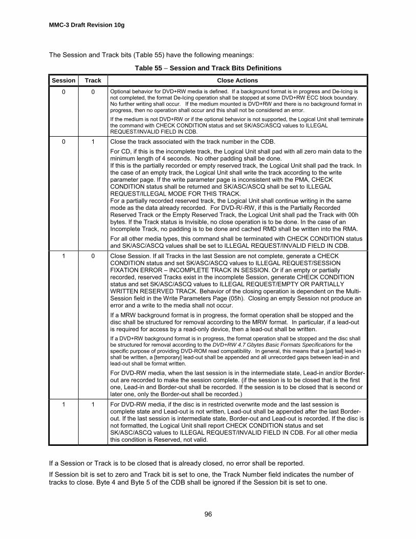
MMC-3 Draft Revision 10g
96
The Session and Track bits (Table 55) have the following meanings:
Table 55 � Session and Track Bits Definitions
Session Track Close Actions
0 0 Optional behavior for DVD+RW media is defined. If a background format is in progress and De-Icing isnot completed, the format De-Icing operation shall be stopped at some DVD+RW ECC block boundary.No further writing shall occur. If the medium mounted is DVD+RW and there is no background format inprogress, then no operation shall occur and this shall not be considered an error.If the medium is not DVD+RW or if the optional behavior is not supported, the Logical Unit shall terminatethe command with CHECK CONDITION status and set SK/ASC/ASCQ values to ILLEGALREQUEST/INVALID FIELD IN CDB.
0 1 Close the track associated with the track number in the CDB.For CD, if this is the incomplete track, the Logical Unit shall pad with all zero main data to theminimum length of 4 seconds. No other padding shall be done.If this is the partially recorded or empty reserved track, the Logical Unit shall pad the track. Inthe case of an empty track, the Logical Unit shall write the track according to the writeparameter page. If the write parameter page is inconsistent with the PMA, CHECKCONDITION status shall be returned and SK/ASC/ASCQ shall be set to ILLEGALREQUEST/ILLEGAL MODE FOR THIS TRACK.For a partially recorded reserved track, the Logical Unit shall continue writing in the samemode as the data already recorded. For DVD-R/-RW, if this is the Partially RecordedReserved Track or the Empty Reserved Track, the Logical Unit shall pad the Track with 00hbytes. If the Track status is Invisible, no close operation is to be done. In the case of anIncomplete Track, no padding is to be done and cached RMD shall be written into the RMA.For all other media types, this command shall be terminated with CHECK CONDITION statusand SK/ASC/ASCQ values shall be set to ILLEGAL REQUEST/INVALID FIELD IN CDB.
1 0 Close Session. If all Tracks in the last Session are not complete, generate a CHECKCONDITION status and set SK/ASC/ASCQ values to ILLEGAL REQUEST/SESSIONFIXATION ERROR � INCOMPLETE TRACK IN SESSION. Or if an empty or partiallyrecorded, reserved Tracks exist in the incomplete Session, generate CHECK CONDITIONstatus and set SK/ASC/ASCQ values to ILLEGAL REQUEST/EMPTY OR PARTIALLYWRITTEN RESERVED TRACK. Behavior of the closing operation is dependent on the Multi-Session field in the Write Parameters Page (05h). Closing an empty Session not produce anerror and a write to the media shall not occur.If a MRW background format is in progress, the format operation shall be stopped and thedisc shall be structured for removal according to the MRW format. In particular, if a lead-outis required for access by a read-only device, then a lead-out shall be written.If a DVD+RW background format is in progress, the format operation shall be stopped and the disc shallbe structured for removal according to the DVD+RW 4.7 Gbytes Basic Formats Specifications for thespecific purpose of providing DVD-ROM read compatibility. In general, this means that a [partial] lead-inshall be written, a [temporary] lead-out shall be appended and all unrecorded gaps between lead-in andlead-out shall be format written.
For DVD-RW media, when the last session is in the intermediate state, Lead-in and/or Border-out are recorded to make the session complete. (if the session is to be closed that is the firstone, Lead-in and Border-out shall be recorded. If the session is to be closed that is second orlater one, only the Border-out shall be recorded.)
1 1 For DVD-RW media, if the disc is in restricted overwrite mode and the last session iscomplete state and Lead-out is not written, Lead-out shall be appended after the last Border-out. If the last session is intermediate state, Border-out and Lead-out is recorded. If the disc isnot formatted, the Logical Unit shall report CHECK CONDITION status and setSK/ASC/ASCQ values to ILLEGAL REQUEST/INVALID FIELD IN CDB. For all other mediathis condition is Reserved, not valid.
If a Session or Track is to be closed that is already closed, no error shall be reported.If Session bit is set to zero and Track bit is set to one, the Track Number field indicates the number oftracks to close. Byte 4 and Byte 5 of the CDB shall be ignored if the Session bit is set to one.

MMC-3 Draft Revision 10g
97
For a CD to close the incomplete track, the following steps are required:1. If necessary, the track is padded with all zero main data to the minimum length of 4 seconds.2. The PMA is consulted in order to locate the largest track number recorded, �N�.3. The boundaries of the track are determined and a PMA entry is written for track N+1. Closing a Track
shall cause cached information for the specified Track to be committed to the medium prior to closing.For CD Closing a Session shall cause the Lead-in and Lead-out to be written for the incomplete Session.Closing a Session when the last session is closed shall not be considered an error. Closing a sessionwhen the last session is empty shall cause no actions to be performed and shall not be considered anerror. For DVD-R/-RW, closing an incomplete or intermediate Session shall cause the Lead-in or Border-in and Border-out to be written for the incomplete or intermediate Session. If the Multi-Session field in theWrite Parameters Page (05h) is set to 00b, a Lead-out shall be appended to last Border-out. Once theLead-out has been written for DVD media, data can not be further appended to the medium.During a Close Track/Session operation that began with the IMMED bit set to one, the Logical Unit shallrespond to commands as follows:a) In response to all commands except REQUEST SENSE, INQUIRY, GET CONFIGURATION, and GET
EVENT/STATUS NOTIFICATION the Logical Unit shall return CHECK CONDITION status and setSK/ASC/ASCQ to NOT READY/LOGICAL UNIT NOT READY/LONG WRITE IN PROGRESS or NOTREADY/LOGICAL UNIT NOT READY/OPERATION IN PROGRESS unless a reservation conflictexists, in that case RESERVATION CONFLICT status shall be returned.
b) In response to the INQUIRY, GET CONFIGURATION, GET EVENT/STATUS NOTIFICATIONcommands, the Logical Unit shall respond as commanded.
c) In response to the REQUEST SENSE command, unless an error has occurred, the Logical Unit shallreturn with SK/ASC/ASCQ values set to NOT READY/LOGICAL UNIT NOT READY/LONG WRITE INPROGRESS or NOT READY/LOGICAL UNIT NOT READY/OPERATION IN PROGRESS(02h/04h/07h), with the sense key specific bytes set for progress indication. See ANSI X3.301:1997,SPC standard for sense key specific field location.
Closing a Track or Session shall cause a Class 1 Event when the command is issued if the Logical Unitbecomes NOT READY. A Class 1 Event shall occur if the medium returns to READY or if the mediumbecomes un-writable. Other Class 1 Events may occur due to closing a Track or Session.Recommended error reporting is defined in Table 56.
Table 56 � Recommended errors for CLOSE TRACK/SESSION Command
Error Reference
Deferred Errors A.1General Errors Table A.2Media Access Errors Table A.3Write Errors Table A.4Fixation Errors Table A.5

MMC-3 Draft Revision 10g
98
5.4 FORMAT UNIT CommandThe FORMAT UNIT command (Table 57) formats a medium into Initiator addressable logical blocks perthe Initiator defined options.The medium may be certified and control structures created for the management of the medium anddefects. There is no guarantee that the medium has not been altered.
Table 57 � Format Unit Command
BitByte
7 6 5 4 3 2 1 0
0 Operation Code (04h)1 Reserved FmtData CmpList Format Code2 Reserved3 (MSB) Interleave Value4 (LSB)5 Control Byte
A FmtData bit of zero indicates that there is no parameter list. A FmtData bit of one indicates that aparameter list is available from the Initiator. For CD-RW, DDCD-RW, DVD-RAM, DVD-RW, and DVD+RWFmtData shall be set to one.The CmpList bit is used in conjunction with the DCRT (Table 60) bit to determine usage of the existingG1-list, G2-list and SDL to construct new G1-list and G2-list (Table 58) on DVD-RAM media. A CmpListbit of zero indicates that the parameter list provided is in addition to those already available to the LogicalUnit. A CmpList bit of one indicates that the parameter list is complete and the Logical Unit is to ignoreany existing parameters. On CD-RW, DDCD-RW, DVD-RW, and DVD+RW media, CmpList bit shall beset to zero.
Table 58 – DVD-RAM Defect List Handling
CmpList DCRT Certification PDL SDL RemarksP-list G1-list G2-list
0 0 Yes Preserved New fromCertification
Disposed Disposed Slow initialization
0 1 No Preserved Preserved Old + Newfrom SDL
Disposed Change linearreplacement to slipping,quickly
1 0 Yes(Partial)Obsolete
Preserved Old plusNew from
Certification
Disposed Disposed Create new defect list bydisposing all except P-listand G1-list
1 1 No Preserved Preserved Disposed Disposed Return to original slippingat the latest certification,quickly
A formatted CD-RW, DDCD-RW, or DVD-RW session shall consist of a single, fixed packet track. Thepacket size specified in the Write Parameters Page defines the packet size for the format operation.If the WRITE TYPE field in the Write Parameters Page is not packet (00b), the FORMAT UNIT commandshall terminate with a CHECK CONDITION and set SK/ASC/ASCQ values to ILLEGALREQUEST/COMMAND SEQUENCE ERROR. If the FP bit in the Write Parameters Page is not set to

MMC-3 Draft Revision 10g
99
one (Fixed Packet), the FORMAT UNIT command shall terminate with a CHECK CONDITION and setSK/ASC/ASCQ values to ILLEGAL REQUEST/COMMAND SEQUENCE ERROR.The Format Code identifies the parameter list format. For DDCD-RW / CD-RW Format Descriptor, theFormat Code shall be set to seven (111b), for other Format Descriptor the Format Code shall be set toone (001b).The Interleave Value field identifies the value to be used when formatting. Interleave Value shall be zero.During the operation of the FORMAT command that began with the IMMED bit set to one, the LogicalUnit shall respond to other commands as follows:a) In response to all commands except REQUEST SENSE, INQUIRY, GET CONFIGURATION, and GETEVENT/STATUS NOTIFICATION the Logical Unit shall return CHECK CONDITION status and setSK/ASC/ASCQ to NOT READY/LOGICAL UNIT NOT READY/FORMAT IN PROGRESS unless areservation conflict exists, in that case RESERVATION CONFLICT status shall be returned.b) In response to the INQUIRY, GET CONFIGURATION, GET EVENT/STATUS NOTIFICATIONcommands, the Logical Unit shall respond as commanded.c) In response to the REQUEST SENSE command, unless an error has occurred, the Logical Unit shallreturn a SK/ASC/ASCQ values set to NOT READY/LOGICAL UNIT NOT READY/FORMAT INPROGRESS, with the sense key specific bytes set for progress indication.During the execution of the FORMAT UNIT command, the Logical Unit shall perform a medium defectmanagement algorithm if the Defect Management Feature is current. The FORMAT UNIT command forDVD-RAM media may not provide a method to receive defect location information from the Initiator.A format data (FmtData) bit of one indicates that the FORMAT UNIT parameter list (see Table 59) shallbe transferred to the Logical Unit. The data sent to the Logical Unit consists of a Format List Header,followed by an initialization pattern descriptor (that may have zero length), followed by zero or one Formatdescriptors. The Format descriptor shall be one of Formattable Capacity Descriptors returned by theREAD FORMAT CAPACITIES command.The FORMAT UNIT command parameter list (Table 59) consists of three descriptors: the Format ListHeader, the Initialization Pattern Descriptor, and the Format Descriptor.
Table 59 � Format Unit Parameter List
BitByte
7 6 5 4 3 2 1 0
0 – 3 Format List Header4 – n Initialization Pattern Descriptor (present if IP = 1)
n+1 ton+8
Format Descriptor
The Format List Header (Table 60) provides several format control bits. Logical Units that implementthese bits give Initiators additional control over the formatting operation. If the Initiator attempts to selectany function not implemented by the Logical Unit, the Logical Unit shall terminate the command withCHECK CONDITION status and SK/ASC/ASCQ values shall be set to ILLEGAL REQUEST/INVALIDFIELD IN PARAMETER LIST.If the Initialization Pattern Descriptor is to be included in parameter data sent to the Initiator, the IP bitshall be set to one, and the data shall begin at a byte offset of 4. If the IP bit is set to zero, theInitialization Pattern Descriptor shall not be included in the Format Unit Parameter data sent to the LogicalUnit, and the Format Descriptor shall begin at byte offset 4.
Table 60 � Format List Header

MMC-3 Draft Revision 10g
100
BitByte
7 6 5 4 3 2 1 0
0 Reserved1 FOV DPRY DCRT STPF IP Try-out IMMED VS2 (MSB) Format Descriptor Length3 (LSB)
A Format Options Valid (FOV) bit of zero indicates that the Logical Unit shall use its default settings forthe DPRY, DCRT, STPF, IP, Try-out, IMMED, and VS bits (see below). When the FOV bit is zero, theHost shall set these bits to zero. If any of these bits are not zero, the Logical Unit shall terminate thecommand with CHECK CONDITION status and set SK/ASC/ASCQ values to ILLEGALREQUEST/INVALID FIELD IN PARAMETER LIST. The default value for VS is vendor specific.The Initiator shall set these bits to zero. If any of these bits are not zero, the Logical Unit shall terminatethe command with CHECK CONDITION status and SK/ASC/ASCQ shall be set to ILLEGALREQUEST/INVALID FIELD IN PARAMETER LIST.A FOV bit of one indicates that the Logical Unit shall examine the setting of the DPRY, DCRT, STPF, IP,and Try-out bits. When the FOV bit is one, the DPRY, DCRT, STPF, IP, and Try-out bits are defined asfollows:A Disable Primary (DPRY) bit, when set to zero, indicates that the Logical Unit shall not use portions ofthe medium identified as defective in the primary defect Plist for Initiator addressed logical blocks. LogicalUnits that support CD-RW, DDCD-RW, DVD-RAM, DVD-RW, or DVD+RW media do not permit theInitiator to set this bit to one. If set to one, the Logical Unit shall terminate the command with CHECKCONDITION status and SK/ASC/ASCQ values shall be set to ILLEGAL REQUEST/INVALID FIELD INPARAMETER LIST.A Disable Certification (DCRT) bit, when set to zero, indicates that the Logical Unit shall perform avendor-specific medium certification operation. This may include the generation of a G1-list (C-list) or aDefect Status bitmap (DS #n bits) in the Format 3 RMD on DVD-RW media. A DCRT bit of one indicatesthat the Logical Unit shall perform no vendor-specific medium certification process or format verificationoperation while executing the FORMAT UNIT command.For CD-RW media, use of the DCRT bit is specific to the format type selected.The STPF bit shall be reserved.An Initialization Pattern (IP) bit of zero indicates that an initialization pattern descriptor is not included andthat the Logical Unit shall use its default initialization pattern. An IP bit of one indicates that aninitialization pattern descriptor is sent to the Logical Unit as part of the FORMAT UNIT parameter list (Seesub-clause 5.4.1).For CD-RW media, the IP bit is reserved.A Try-out bit of one indicates that the Logical Unit shall not alter the media format, but shall examinewhether the specified FORMAT command can be performed without error, based on available informationbefore starting the formatting.For CD-RW media, the Try-out bit is reserved.An immediate (IMMED) bit of zero indicates that status shall be returned after the format operation hascompleted. An IMMED bit value of one indicates that the Logical Unit shall return status as soon as thecommand descriptor block has been validated, and the entire Format Descriptor has been transferred.If the IMMED bit is set to one, and a REQUEST SENSE command is issued during the formattingoperation, the Logical Unit shall return a sense key of NOT READY and an ASC of LOGICAL UNITNOT READY, FORMAT IN PROGRESS, unless an error has occurred. The sense key specific bytes shallbe set to the percentage of the operation that has completed. The sense key specific field contains avalue from 0 to FFFFh, where FFFFh indicates the formatting is completed.

MMC-3 Draft Revision 10g
101
The Vendor Specific (VS) bit is vendor-specific.The Format Descriptor Length field in the Format list header specifies the total length in bytes of theFormat descriptors that follow and does not include the initialization pattern descriptor or initializationpattern, if any.The Format Descriptor Length shall be set to 8. Any other value in this field shall cause CHECKCONDITION status to be returned and SK/ASC/ASCQ values shall be set to ILLEGALREQUEST/INVALID FIELD IN PARAMETER LIST.
5.4.1 Initialization PatternThe initialization pattern option specifies that the logical blocks contain the specified initialization pattern.The initialization pattern descriptor (Table 61) is sent to the Logical Unit as part of the FORMAT UNITparameter list.
Table 61 � Initialization Pattern Descriptor
BitByte
7 6 5 4 3 2 1 0
0 IP Modifier SI Reserved1 Pattern Type2 (MSB) Initialization Pattern Length3 (LSB)4: Initialization Patternn
The IP Modifier field specifies the type and location of a header that modifies the initialization pattern (seeTable 62).
Table 62 – IP Modifier Field
IP Modifier Descriptor
00b No header. The device server shall not modify the initialization pattern.01b The device server shall overwrite the initialization pattern to write the logical block address in the
first four bytes of the logical block. The LBA shall be written with the most significant byte first.10b The device server shall overwrite the initialization pattern to write the logical block address in the
first four bytes of each physical block contained within the logical block. The lowest numberedlogical block or part there of which occurs within the physical block is used. The LBA shall bewritten with the most significant byte first.
11b Reserved
The Initialization Pattern Type field (Table 63) indicates the type of pattern the device server shall use toinitialize each logical block within the application client accessible portion of the medium. All bytes withina logical block shall be written with the initialization pattern. The IP Modifier field modifies the InitializationPattern.

MMC-3 Draft Revision 10g
102
Table 63 – Initialization Pattern Type
Initialization PatternType
Description
00h Use default pattern1
01h Repeat the initialization pattern as required to fill the logical block.2
02h � 7Fh Reserved80h - FFh Vendor Specific
Notes:1. If the initialization pattern length is not zero the device server shall terminate the command with CHECKCONDITION status and SK/ASC/ASCQ shall be set to ILLEGAL REQUEST/INVALID FIELD IN PARAMETERLIST.2. If the initialization pattern length is zero the device server shall terminate the command with CHECKCONDITION status and SK/ASC/ASCQ shall be set to ILLEGAL REQUEST/INVALID FIELD IN PARAMETERLIST.
A Security Initialize (SI) bit of one indicates that the device server shall attempt to write the initializationpattern to all areas of the media including those that may have been reassigned. A SI bit of one shall takeprecedence over any other FORMAT UNIT field. The initialization pattern shall be written using a securityerasure write technique. Application clients may choose to use this command multiple times to fully erasethe previous data. Such security erasure write technique procedures are outside the scope of thisstandard. The exact requirements placed on the security erasure write techniques are vendor-specific.The intent of the security erasure write is to render any previous user data unrecoverable by any analogor digital technique.An SI bit of zero indicates that the device server shall initialize the application client accessible area of themedia. The device server is not required to initialize other areas of the media. However, the device servershall format the medium as defined in the FORMAT UNIT command.When the SI bit is one, the device server need not rewrite (format) header and other information notpreviously accessible to the application client. If any area of the medium that previously was accessible tothe application client cannot be written, the device server shall terminate the command with CHECKCONDITION status and the sense key shall be set to MEDIUM ERROR with the appropriate ASC for thecondition.The Initialization Pattern Length field indicates the number of bytes contained in the initialization pattern.If the length exceeds the current logical block size the device server shall terminate the command withCHECK CONDITION status and SK/ASC/ASCQ values shall be set to ILLEGAL REQUEST/INVALIDFIELD IN PARAMETER LIST. The IP Modifier field modifies the pattern.The Format descriptor specifies an eight-byte entry.

MMC-3 Draft Revision 10g
103
5.4.2 CD-RW Format Descriptor, Format Code 111bIf the Format Code, in the CDB, is 111b the CD-RW Format Descriptor defined in Table 64 shall be sent.
Table 64 � CD-RW Format Descriptor
BitByte
7 6 5 4 3 2 1 0
0 SESS Grow Reserved1 Reserved2 Reserved3 Reserved4 (MSB)5 Format Size67 (LSB)
If both the Grow and Session bits are set to zero the format operation shall format (Format Size) userdata blocks. Format Size shall be integrally divisible by the Packet Size field in the Write ParametersPage. The first formatted user data block shall be LBA 0. Existing information on the disc may beoverwritten. After the format, a single session containing a single, fixed packet track exists on themedium.If the Grow bit is set to zero and the Session bit is set to 1 the format operation shall create a new sessionthat contains (Format Size) user data blocks. Format Size shall be integrally divisible by the Packet Sizefield in the Write Parameters Page. If the last session on the disc is not complete when this command isissued, a CHECK CONDITION status shall be generated.A Grow bit of 1 indicates that the final session shall be "grown" to (Format Size) from its original size. Thisis accomplished by appending packets to the existing session, writing a new Lead-out, and updating thePMA and Lead-in to change the track size to reflect the new size. Data in existing packets shall not beaffected. If the Format Size is smaller than the existing size, a CHECK CONDITION status shall bereturned. The order of updating the PMA, Lead-in, Lead-out, and data area is not specified.The session bit shall be ignored when the Grow bit is set.
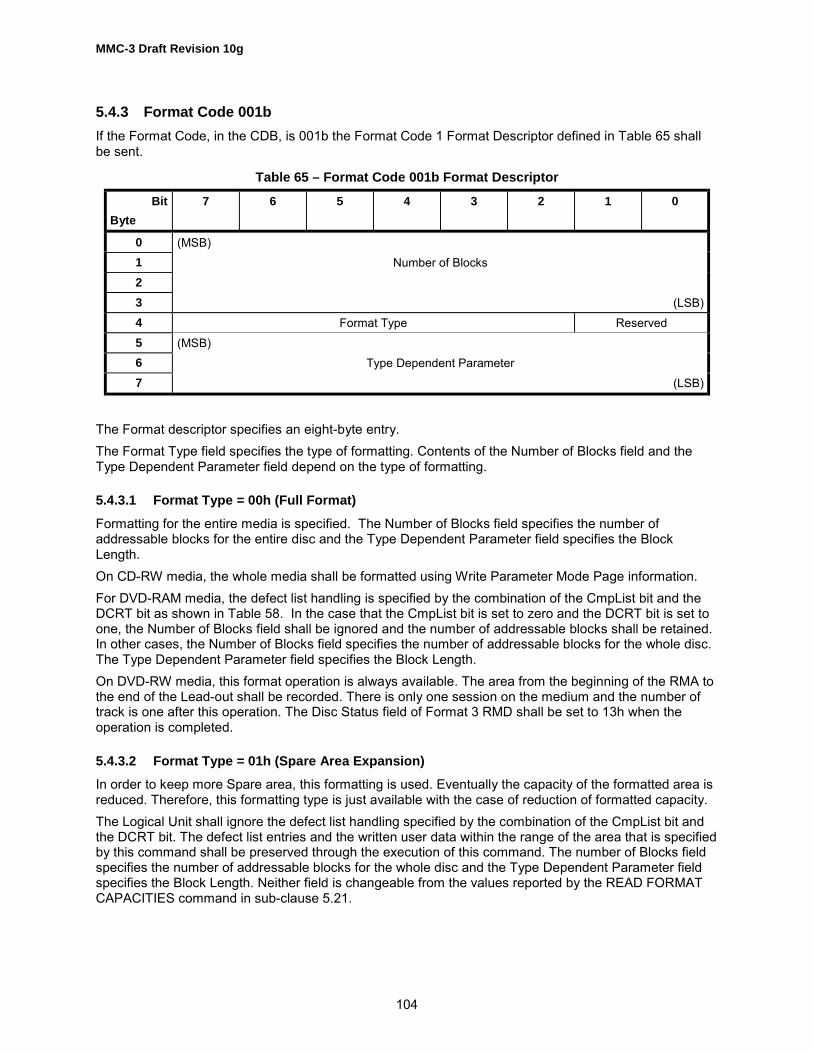
MMC-3 Draft Revision 10g
104
5.4.3 Format Code 001bIf the Format Code, in the CDB, is 001b the Format Code 1 Format Descriptor defined in Table 65 shallbe sent.
Table 65 – Format Code 001b Format Descriptor
BitByte
7 6 5 4 3 2 1 0
0 (MSB)1 Number of Blocks23 (LSB)4 Format Type Reserved5 (MSB)6 Type Dependent Parameter7 (LSB)
The Format descriptor specifies an eight-byte entry.The Format Type field specifies the type of formatting. Contents of the Number of Blocks field and theType Dependent Parameter field depend on the type of formatting.
5.4.3.1 Format Type = 00h (Full Format)Formatting for the entire media is specified. The Number of Blocks field specifies the number ofaddressable blocks for the entire disc and the Type Dependent Parameter field specifies the BlockLength.On CD-RW media, the whole media shall be formatted using Write Parameter Mode Page information.For DVD-RAM media, the defect list handling is specified by the combination of the CmpList bit and theDCRT bit as shown in Table 58. In the case that the CmpList bit is set to zero and the DCRT bit is set toone, the Number of Blocks field shall be ignored and the number of addressable blocks shall be retained.In other cases, the Number of Blocks field specifies the number of addressable blocks for the whole disc.The Type Dependent Parameter field specifies the Block Length.On DVD-RW media, this format operation is always available. The area from the beginning of the RMA tothe end of the Lead-out shall be recorded. There is only one session on the medium and the number oftrack is one after this operation. The Disc Status field of Format 3 RMD shall be set to 13h when theoperation is completed.
5.4.3.2 Format Type = 01h (Spare Area Expansion)In order to keep more Spare area, this formatting is used. Eventually the capacity of the formatted area isreduced. Therefore, this formatting type is just available with the case of reduction of formatted capacity.The Logical Unit shall ignore the defect list handling specified by the combination of the CmpList bit andthe DCRT bit. The defect list entries and the written user data within the range of the area that is specifiedby this command shall be preserved through the execution of this command. The number of Blocks fieldspecifies the number of addressable blocks for the whole disc and the Type Dependent Parameter fieldspecifies the Block Length. Neither field is changeable from the values reported by the READ FORMATCAPACITIES command in sub-clause 5.21.

MMC-3 Draft Revision 10g
105
5.4.3.3 Format Type = 04h (Zone Reformat)The Zoned formatting for a zone of the media is specified where the size of zone is not constant acrosszones. The defect list handling is specified by the combination of the CmpList bit and the DCRT bit asshown Table 58. The Number of Blocks field specifies the number of addressable blocks for the zone andthe Type Dependent Parameter field specifies the Zone number of the zone to be formatted. If a sparesector is used as a replacement for another zone so that the zoned formatting cannot be preformed, thecommand shall be terminated with a CHECK CONDITION status, SK/ASC/ASCQ values shall be setto MEDIUM ERROR/ZONED FORMATTING FAILED DUE TO SPARE LINKING, and the sense keyspecific bytes set to zone number of the first zone that has a spare linking into the designated zone.The discarding of G1-list, G2-list, and SDL is only applicable to defects within the zone being reformatted.
5.4.3.4 Format Type = 05h (Zone Format)The Zoned formatting for a zone of the media is specified where the size of zone is constant for eachzone, e.g. floppy media where each track is labeled a zone. The Number of Blocks field specifies thenumber of addressable blocks for the zone and the Type Dependent Parameter field specifies the Zonenumber of the zone to be formatted. The zone number shall be in the range of 0 to the Type DependentParameter reported in READ FORMAT CAPACITIES command in sub-clause 5.21.
5.4.3.5 Format Type = 10h (CD/DVD-RW Full Format)Formatting to create a session on CD/DVD-RW media is specified. The created session shall become theonly session on the medium. The Number of Blocks field specifies the number of addressable blocks forthe new session and the Type Dependent Parameter field specifies the Fixed Packet Size for CD or set toECC block size (16) for DVD-RW. The number of blocks field may be adjusted to a value less than orequal to the values reported by the READ FORMAT CAPACITIES command, sub-clause 5.21. TheLogical Unit shall round the Number of Blocks up to be an integral multiple of the packet size for CD orset to ECC block size (16) for DVD-RW. The Packet Size field shall not be adjusted. In the case of CDmedia, if a different Fixed Packet Size is desired, the Initiator shall modify the Write Parameters Page.On DVD-RW media, this format operation is always available. The track number in the created session isone after this operation. The Disc Status field of Format 3 RMD shall be set to 12h when the operation iscompleted.
5.4.3.6 Format Type = 11h (CD/DVD-RW Grow Session)In the case of CD-RW, formatting to expand the last session is specified. The Number of Blocks fieldspecifies the number of addressable blocks to be enlarged and the Type Dependent Parameter fieldspecifies the Packet Length. The Number of Blocks field may be adjusted to a value greater than theexisting Session size and less than or equal to the values reported by the READ FORMAT CAPACITIEScommand. The Logical Unit shall round the Number of Blocks up to be an integral multiple of the packetsize. The Packet Size field shall not be adjusted.In the case of DVD-RW, formatting to expand the last session and enter the last session program areainto intermediate state is specified. The Number of Blocks field specifies the number of addressableblocks to be added to current session capacity and the Type Dependent Parameter field is set to ECCblock size (16). The Logical Unit shall round the Number of Blocks up to be an integral multiple of theECC block size.This format operation is available only when a disc is in restricted overwrite mode and the last session isin a complete state. Growing of session operation shall start from the next sector of End Sector Numberof Track #n field that is corresponded to the last track. End PSN of Data Area and Start PSN of thecurrent Lead-out/Border-out field of Lead-in/Border-in shall be changed to reflect the expanded session.The number of sessions and tracks does not change after this operation.

MMC-3 Draft Revision 10g
106
5.4.3.7 Format Type = 12h (CD/DVD-RW Add Session)Formatting to add a new session to a CD/DVD-RW media is specified. The Number of Blocks fieldspecifies the number of addressable blocks for the new session and the Type Dependent Parameter fieldspecifies the Fixed Packet Size for CD or set to ECC block size (16) for DVD-RW. The Number of Blocksfield may be adjusted to a value less than or equal to the values reported by the READ FORMATCAPACITIES Command, 5.21.The Logical Unit shall round the Number of Blocks up to be an integral multiple of the packet size for CDor the ECC block size for DVD. The Packet Size field shall not be adjusted. On CD media, if a differentFixed Packet Size is desired, the Initiator shall modify the Write Parameters Page.On DVD-RW media, this format operation is available only when a disc is in restricted overwrite mode andthe last session is in a complete state. Start PSN of the next Border-in field in the previous Border-in/Lead-in shall be updated.
5.4.3.8 Format Type = 13h (DVD-RW Quick Grow the last Session)Formatting to expand the last session and enter the last session into intermediate state of a DVD-RWmedium is specified. The Number of Blocks field specifies the number of addressable blocks to be addedto current session capacity and the Type Dependent Parameter field is set to ECC block size (16). TheLogical Unit shall round the Number of Blocks up to be an integral multiple of the ECC block size.This format operation is available only when the disc is in restricted overwrite mode and the last sessionis complete state. Growing of session operation shall start from the next sector of End Sector Number ofTrack #n field that is corresponded to the last track.The number of sessions and tracks does not change after this operation. The Disc Status field of Format3 RMD shall be set to 13h when the operation is completed. End PSN of Data Area field in Lead-in/Border-in of the last session shall be set to 30000h. And Start PSN of the current Border-out and StartPSN of the next Border-in field in Lead-in/Border-in of the last session shall be set to 00h.

MMC-3 Draft Revision 10g
107
5.4.3.9 Format Type = 14h (DVD-RW Quick Add Session)Formatting to add a new intermediate state session to an existing session on DVD-RW media is specified.At least one or more sessions shall exist on a medium and the last session shall not be intermediate statebefore start this operation.The area from the beginning of Border-in that follows the last Border-out, user data blocks and 32 ECCblocks with Lead-out attribute is recorded. Start PSN of the next Border-in field in the previous Border-in/Lead-in shall not be changed to reflect the intermediate state session that is added.If FORMAT UNIT command with this Format Type is issued when the last session is already intermediatestate, the command shall be terminated with CHECK CONDITION status and SK/ASC/ASCQ values shallbe set to ILLEGAL REQUEST/INVALID FIELD IN PARAMETER LIST.The Number of Blocks field specifies the number of addressable blocks for the new session and the TypeDependent Parameter field is set to ECC block size (16). The Number of Blocks field may be adjusted toa value less than or equal to the values reported by the READ FORMAT CAPACITIES command. TheLogical Unit shall round the Number of Blocks up to be an integral multiple of the ECC block size.
5.4.3.10 Format Type = 15h (DVD-RW Quick)Formatting to create an Intermediate State session on DVD-RW media is specified. The created sessionshall become the only session on the medium. The Number of Blocks field specifies the number ofaddressable blocks for the new session and the Type Dependent Parameter field is set to ECC block size(16). The Number of Blocks field may be adjusted to a value less than or equal to the values reported bythe READ FORMAT CAPACITIES command. The Logical Unit shall round the Number of Blocks up to bean integral multiple of the ECC block size for DVD.This format operation is always available. If a disc is to be formatted that is blanked, new intermediatestate session is created at the beginning of the disc and the recording mode is changed to restrictedoverwrite mode. The number of track in the created session is one after this operation. The Disc Statusfield of Format 3 RMD shall be set to 13h when the operation is completed.
5.4.3.11 Format Type = 20h (Full Format, DVD+RW 3.0 GB) (OBSOLETE)Formatting for the whole media is specified. The Number of Blocks field specifies the maximum number ofaddressable blocks for the whole disc and the Type Dependent Parameter field specifies the sparingparameters SL and SI. The Logical Unit shall verify that SL and SI are usable values (i.e. values that donot cause overflow of the SDL).If the Multi-Session Field (Table 349) in the Write Parameter Page is 11b, the Logical Unit shall erase theremaining area of the disc.

MMC-3 Draft Revision 10g
108
5.4.3.12 Format Types = 24h, (MRW Full Format)The CD-RW disc shall be formatted according to the CD-MRW Defect Management & PhysicalFormatting Specification (sub-clause 2.2).The Number of Blocks parameter shall have the value 0xFFFFFFFF. If the field contains any other value,the Logical Unit shall terminate the command with CHECK CONDITION status and set SK/ASC/ASCQvalues to ILLEGAL REQUEST/INVALID FIELD IN PARAMETER BLOCK. The number of blocksformatted shall be exactly the number of blocks reported by the READ FORMAT CAPACITIES commandfor type 24h.The Type Dependent Parameter has the meaning of �New format� when it has the value 000000h. TheType Dependent Parameter has the meaning of �Restart format� when it has the value 000001h.For a New Format operation, the medium format shall be performed to create a single track, singlesession of fixed packets of size = 32, mode 2 form 1 data. Defect management tables are initialized as apart of the formatting process.Much of the formatting is performed in background. The initiator may suspend a background formatprocess by issuing the CLOSE TRACK/SESSION command with Session = 1 and Track = 0.For a Restart Format operation, the Logical Unit shall continue formatting a suspended backgroundformat process. If there is no suspended background format to continue, the Logical Unit shall terminatethe command with CHECK CONDITION status and set SK/ASC/ASCQ values to ILLEGAL REQUEST/COMMAND SEQUENCE ERROR.Certification of the format is based upon current medium status as shown in Table 66.
Table 66 – Use of DCRT when MRW Formatting
Current Disc Status DCRT = 0 DCRT = 1
Physically Blank Write entire surface format,verify MRW structures and userareas
Write entire surface format,verify only MRW structures
Written, but not MRW Formatted(includes logically blank)
Write format, verify MRW structures and user areas. The CD-MRW DM&PF Specification requires certification of the user area.
MRW formatted Reinitialize MRW structures, verify MRW structures and userareas. The CD-MRW DM&PF Specification requires certificationof the user area.
In all cases when:
• DCRT is cleared to zero,
• the initiator requests to WRITE the sector at LBA = N, and
• sector N has not yet been verified by the format operation,.The WRITE command shall be treated as a WRITE and VERIFY command.
5.4.3.12.1 Background Formatting: New FormatIf the IMMED bit is cleared to zero, formatting begins with the MTA initialization. Once that hascompleted, the FORMAT UNIT command terminates with GOOD status and continues the format inbackground. Once MTA initialization has been completed, the disc is MRW available.If the IMMED bit is set to one, the FORMAT UNIT command terminates with GOOD status and proceedswith all format-writing functions performed in the background. If any media accessing command is issuedprior to the disc being MRW available, the Logical Unit shall terminate the command with CHECK

MMC-3 Draft Revision 10g
109
CONDITION status and set SK/ASC/ASCQ values to NOT READY/LOGICAL UNIT NOTREADY/FORMAT IN PROGRESS .Once the formatting process has achieved MRW available, format progress may be tracked. If no errorhas occurred, then in response to a TEST UNIT READY command, the Logical Unit shall terminate thecommand with GOOD status and SK/ASC/ASCQ values shall be set to NO SENSE/LOGICAL UNIT NOTREADY/FORMAT IN PROGRESS. The sense key specific bytes shall be set as a progress indicator(Table 67).
Table 67 – Sense Key Specific Bytes in Sense Data
BitByte
7 6 5 4 3 2 1 0
15 SKSV Reserved1617
(MSB) Progress Indication(LSB)
The progress indication field is a percent complete indication in which the returned value is the numeratorthat has 65536 (10000h) as its denominator. The progress indication shall be based upon the totaloperation.Once the background format operation has completed, the CD-RW Logical Unit shall post a BackgroundFormat Completed Media Event. The response to a TEST UNIT READY command shall then be: thecommand shall be terminated with GOOD status and SK/ASC/ASCQ values shall be set to NOSENSE/NO ADDITIONAL SENSE INFORMATION, and SKSV shall be cleared to zero.
5.4.3.12.2 Stopping and Restarting a Background Format
If a format is executing in background:
• Only issuing the CLOSE TRACK/SESSION command may stop the formatting process.
• The inactivity timer (CD-ROM Mode Page) is disabled. This ensures that lack of initiator activity doesnot allow a spin down during background formatting.
• If the initiator sends a SCSI command which requires that the medium spin down, the CD-RW LogicalUnit shall terminate the command with CHECK CONDITION status and set SK/ASC/ASCQ values toNOT READY/LOGICAL UNIT NOT READY/FORMAT IN PROGRESS. Example: START STOPUNIT command is issued with Start = 0.
• If the initiator/Logical Unit physical interface provides a command layer with commands that cancause the medium to spin down, then those commands shall be terminated with the appropriate errorstatus. For example, if the interface is ATA and the command is IDLE or SLEEP, then the commandshall be terminated with the status register ERROR bit set to true.
• If any other command is issued to the CD-RW Logical Unit, it shall be executed normally.Whenever a CD-RW disc is mounted, the CD-RW Logical Unit shall examine the disc structures. Thestate of formatting is reported in the Disc Information Block (Table 162).The initiator may restart a suspended background format at any time. If the format has alreadycompleted, this shall not be considered an error.The initiator may choose to write to the disc while an incomplete format is NOT in progress. If the initiatorwrites to any LBA which is beyond the start of the current, temporary lead-out, the Logical Unit shallrestart the format automatically. If the Logical Unit performs an automatic restart, the initiator shall beinformed with the BGformatRestarted event.

MMC-3 Draft Revision 10g
110
5.4.3.12.3 Recovering an Incomplete FormatThe background format can be stopped in a controlled way as described in 5.4.3.12.2, above. A HardReset or loss of power can also stop a background format operation, but not in a controlled way. This canproduce a disc which is partially formatted, however, it may also contain recoverable data.An initiator operated recovery application can be produced in order to recover data from the disc. Sincethe defect management system may be corrupted, it is recommended that the READ CD MSF be used fordata recovery.The CD-MRW Defect Management & Physical Formatting specification describes a method forcheck-pointing the background format progress. If the MTA is not corrupted, then a format restart restartsthe formatting operation from the last checkpoint. If the MTA is corrupted and either the MIP or the MDTis unrecoverable, then a new format is required.

MMC-3 Draft Revision 10g
111
5.4.3.13 Format Type = 26h (Full Format, DVD+RW)DVD+RW Basic Format, Mandatory when the Write bit in the DVD+RW Feature Descriptor is set to one.The Number of Blocks field shall be set to either the value returned by the READ FORMAT CAPACITIEScommand or 0xFFFFFFFF. The drive shall accept either value. If any other value is sent by the host,then the drive shall terminate the command with CHECK CONDITION status and set sense bytes (SenseKey/ASC/ASCQ) to ILLEGAL REQUEST/ILLEGAL VALUE IN PARAMETER BLOCK. Implementation ofbackground format is mandatory.The Type Dependent Parameter has the meaning of �New format� when it has the value 000000h. TheType Dependent Parameter has the meaning of �Restart format� when it has the value 000001h.Much of the formatting is performed in background. The initiator may suspend a background formatprocess by issuing the CLOSE TRACK/SESSION command. See sub-clause 5.3.For a Restart Format operation, the Logical Unit shall continue a suspended background format. If thereis no suspended background format to continue, the Logical Unit shall terminate the command withCHECK CONDITION status and set SK/ASC/ASCQ values to ILLEGAL REQUEST, COMMANDSEQUENCE ERROR.DCRT has no meaning when formatting type 26h. The device ignores DCRT.

MMC-3 Draft Revision 10g
112
5.4.3.13.1 Background Formatting for Format Type 26hThe background formatting process is best illustrated in Figure 41.
Figure 41 – Background Process Flow
5.4.3.13.2 Background Formatting: Getting StartedAccording to the DVD+RW 4.7 Gbytes Basic Format Specifications: �The disc shall be consideredpartially formatted if the lead-in has been recorded from the Inner Disc Test Zone up to the Data Zone.�Once the disc has completed the partial formatted state, the format operation may continue inbackground. That is, the FORMAT UNIT command shall terminate.All format write functions shall write only complete DVD+RW ECC blocks.
De-icecomplete
Format unit command,new format
Format Restart
Close w/oTemplead-out
Close w/Templead-out
Close Track/Session
Blank orincompleteformat
Perform Partialformat
De-ice data zoneDVD+RW Status = 2
Write partiallead-in
Fill gaps andWrite TempLead-out
DVD+RWStatus = 1
Send BGformat completeevent and set DVD+RWStatus = 3

MMC-3 Draft Revision 10g
113
5.4.3.13.3 Background Formatting: Stopping the FormatIf a format is executing in background:
• The formatting process may be stopped by issuing the CLOSE TRACK/SESSION command.
• If the initiator sends a SCSI command block which requires that the medium spin down, the LogicalUnit shall terminate the command with CHECK CONDITION status and set SK/ASC/ASCQ values toNOT READY, LOGICAL UNIT NOT READY, FORMAT IN PROGRESS. Example: START STOPUNIT command is issued with Start = 0.
• If the initiator/Logical Unit physical interface provides a command layer with commands that cancause the medium to spin down, then those commands shall be terminated with the appropriate errorstatus. For example if the interface is ATA and the command is IDLE or SLEEP, then the commandshall be terminated with the status register ERROR bit set to true.
• If any other command is issued to the Logical Unit, it shall be executed normally.Whenever a DVD+RW disc is mounted, the Logical Unit shall examine the disc structures. The state offormatting is reported in the Disc Information Block as returned by the READ DISC INFORMATIONcommand.
5.4.3.13.4 Background Formatting: RestartingIf an incompletely formatted disc is mounted in a write-capable DVD+RW Logical Unit, formatting shall notcontinue automatically at that time.The initiator may explicitly restart the format by sending the format command again with restart specifiedin the type dependent parameter of the format descriptor.The initiator may implicitly restart the format by sending a write command requesting that some LBAbeyond the currently formatted region be written. In this case, the Logical Unit shall post theBGformatRestarted media event.The FDCB (See DVD+RW 4.7 Gbytes Basic Format Specifications ) should be consulted in order tocorrectly restart the background format.
5.4.3.13.5 Background Formatting: Progress ReportingIf the IMMED bit is set to one, then the FORMAT UNIT command terminates with GOOD status andproceeds with all format writing functions performed in the background. If any media accessing commandis issued while the initial areas are being formatted, the DVD+RW Logical Unit shall terminate thecommand with CHECK CONDITION status and set SK/ASC/ASCQ values to NOT READY, LOGICALUNIT NOT READY, FORMAT IN PROGRESS.Regardless of the setting of IMMED, once the partial formatting has completed, background formattingbegins. The initiator may monitor format progress. The response to a TEST UNIT READY commandshall be: the command shall be terminated with GOOD status and SK/ASC/ASCQ values shall be set toNO SENSE/LOGICAL UNIT NOT READY/ FORMAT IN PROGRESS, unless an error has occurred. Thesense key specific bytes (Table 68) shall be set as a progress indicator.
Table 68 – Sense Key Specific Bytes in Sense Data
BitByte
7 6 5 4 3 2 1 0
15 SKSV Reserved1617
(MSB) ProgressIndication (LSB)

MMC-3 Draft Revision 10g
114
The progress indication field is a percent complete indication in which the returned value is the numeratorthat has 65 536 (10000h) as its denominator. The progress indication shall be based upon the totaloperation.Once the background format operation has completed, the DVD+RW Logical Unit shall post aBackground Format Completed Media Event. The response to a TEST UNIT READY command shallthen be: the command shall be terminated with GOOD status and SK/ASC/ASCQ values shall be set toNO SENSE, NO ADDITIONAL SENSE, NO ADDITIONAL SENSE QUALIFIER, and SKSV shall becleared to zero.
5.4.3.13.6 Background Formatting: Formatting Concurrently with WritingOnce the partial format has completed, the initiator may issue a write to any address that exists afterformatting has completed. It is possible for the Logical Unit to locate and write the data as requested.Suppose some write request is made to a DVD+RW ECC block that is completely blank. When thisoccurs, the data shall be placed into the correct ECC block buffer positions and un-addressed sectorpositions within the buffer shall be zero filled. For example, suppose a write command requests to writeonly the fifth and sixth sectors within a DVD+RW ECC block. The Logical Unit shall load a 16-sectorbuffer as shown in Table 69.
Table 69 – Writing User Data During Format Operation
ECC Block Sector Data Content ECC Block Sector Data Content
ECC Block Sector 0 Zero fill ECC Block Sector 8 Zero fill
ECC Block Sector 1 Zero fill ECC Block Sector 9 Zero fillECC Block Sector 2 Zero fill ECC Block Sector 10 Zero fill
ECC Block Sector 3 Zero fill ECC Block Sector 11 Zero fill
ECC Block Sector 4 User Data ECC Block Sector 12 Zero fillECC Block Sector 5 User Data ECC Block Sector 13 Zero fill
ECC Block Sector 6 Zero fill ECC Block Sector 14 Zero fill
ECC Block Sector 7 Zero fill ECC Block Sector 15 Zero fill
The difficulty is simply that this allows the blank area to become fragmented.Note: All blank areas shall be written either with initiator data or format patterns. The Logical Unit shall fillall blank fragments.
5.4.3.13.7 Background Formatting: Formatting Concurrently with ReadingIf the initiator attempts to read the media, the result shall be identical to the case where format hascompleted. Thus, written sectors shall return the data written in the sector. If the sector has not yet beende-iced, then the Logical Unit shall return all zeros in the place of sector data.
5.4.3.13.8 Background Formatting: Early EjectWhen the initiator wishes to stop the background format, it shall first notify the Logical Unit with theCLOSE TRACK/SESSION command.When track = 0 and session = 0, the Logical Unit shall stop the format at an ECC block boundary andrecord the formatting state in the FDCB. At that point, background formatting shall be stopped.When track = 0 and session = 1, the Logical Unit shall first perform all ECC block format writes necessaryto bring the disc to a state where exactly 2 zones exist: the inner zone is entirely written and the outerzone is entirely blank. A temporary lead-out is appended to ensure that the disc is readable in DVD read-only devices. The Logical Unit shall record the formatting state in the FDCB. Finally, the lead-in isupdated to mark the restart point for the format continuation.

MMC-3 Draft Revision 10g
115
5.4.3.14 Format Type = 28h (DDCD-RW quick format).When the Intermediate bit is set to 1, the new formatting operation, which realizes quasi fast formatting,shall be performed. At the first formatting operation, a specified small area is formatted quickly. Additionalformatting operations are performed when necessary. The new format operation creates a single trackof fixed packets of size = 32, mode2form1 data, with the following actions:1. A PMA entry is updated for the single track.2. The Lead-in area is not recorded.3. The Pre Gap of the track is recorded.When ejecting, the last formatted address is recorded in the medium.As long as a Session on a DDCD-RW(ReWritable) disc is not finalized, the Recording Management Area(RMA) is used for intermediate storage. The RMA contains information about the Packet recording stateon the DDCD-RW, this information is encoded as main data in the Lead-in Area.In the Format UNIT command, the Number of Blocks field specifies the number of addressable blocks tobe enlarged and the Type Dependent Parameter field specifies the Packet Length. The Number of Blocksfield shall be adjusted to a value greater than the existing Track size and less than or equal to the valuereported by the Read Format Capacities command. The Logical Unit shall round the Number of Blocks upto be an integral multiple of the Packet Length.Recommended error reporting is defined in Table 70.
Table 70 – Recommended errors for FORMAT UNIT Command
Error Reference
Deferred Errors A.1General Errors Table A.2Media Access Errors Table A.3Write Errors Table A.4FORMAT COMMAND FAILED Table A.1CANNOT FORMAT MEDIUM - INCOMPATIBLE MEDIUM Table A.1

MMC-3 Draft Revision 10g
116
5.5 GET CONFIGURATION CommandThis command is intended to provide information to the initiator about the overall capabilities of the deviceand, specifically, the current capabilities of the device.The GET CONFIGURATION command, Table 71, requests that the device respond with the configurationof the device and medium.The configuration of the device, is described by the Logical Unit supported Features. The currentlydefined Features are listed in Table 370. The maximum number of Features is 65 536; and the maximumnumber of bytes that a device may return, to describe its set of supported Features, is 65 534. Featurelists longer than 65 534 bytes require multiple commands.Persistent Prevent may be used to control when changes occur. If a Persistent Prevent is in place, theconfiguration should not change except under initiator control.
Table 71 � GET CONFIGURATION Command Descriptor Block
BitByte
7 6 5 4 3 2 1 0
0 OPERATION CODE (46h)1 Reserved Reserved RT2 (MSB) Starting Feature Number3 (LSB)4 Reserved5 Reserved6 Reserved78
(MSB) Allocation Length(LSB)
9 Control
The RT (Requested Type) (Table 72) field indicates the set of Feature Descriptors desired from theLogical Unit.
Table 72 � RT Field definition
RT Field Description Starting Feature Number (SFN) Usage
00b Indicates that the Logical Unit shall return theFeature Header and all Feature Descriptorssupported by the Logical Unit whether or notthey are currently active.
The first Feature Descriptor returned shall havea Feature number greater than or equal to theSFN.
01b Indicates that the Feature Header and onlythose Feature Descriptors that have theirCurrent bit set shall be returned.
10b Indicates that exactly one Feature Header andzero or one Feature Descriptors be returned. Ifthe Logical Unit does not support the indicatedFeature, no Feature Descriptor is returned.Note: this may be used to request Feature 0,which is a list of Profiles.
The SFN specifies the Feature Descriptor thatshall be returned.
11b Reserved

MMC-3 Draft Revision 10g
117
The Starting Feature Number field indicates the first Feature number to be returned. All supportedFeature numbers higher than the Starting Feature Number shall be returned.The Allocation Length field specifies the maximum length in bytes of the Get Configuration response data.An Allocation Length field of zero indicates that no data shall be transferred. This condition shall not beconsidered an error.
5.5.1 GET CONFIGURATION response dataThe GET CONFIGURATION response Data (Table 74) consists of a header field and zero or morevariable length feature descriptors.
Table 73 � GET CONFIGURATION response data format
BitByte
7 6 5 4 3 2 1 0
0 - 7 Feature Header8 - n Feature Descriptor(s)
The Feature Header field to be returned is shown in Table 74.
Table 74 � Feature Header
BitByte
7 6 5 4 3 2 1 0
0 (MSB)1 Data Length23 (LSB)4 Reserved5 Reserved6 (MSB) Current Profile7 (LSB)
The Data Length field indicates the amount of data available given a sufficient allocation length followingthis field. This length shall not be truncated due to an insufficient Allocation Length. If the Data Length isgreater than 65 530 bytes, multiple GET CONFIGURATION commands with different Starting FeatureNumbers are required for the initiator to read all configuration data. This field is adjusted as appropriatefor the given Starting Feature Number.The Current Profile field shall indicate the Logical Unit�s current Profile. The Logical Unit shall choose themost appropriate current Profile from the list of Profiles (see Table 372) with their CurrentP bit set. If thereare no Profiles currently active, this field shall contain zero.The Feature Descriptor(s) generic format returned is defined in Table 75. Each individual Featuredescription is defined in the appropriate sub-clause.

MMC-3 Draft Revision 10g
118
Table 75 – Feature Descriptor generic format
BitByte
7 6 5 4 3 2 1 0
0 (MSB) Feature Code1 (LSB)2 Reserved Version Persistent Current
3 Additional Length4 - n Feature Dependent Data
The Feature Code field contains the code number assigned to the Feature.Version field, see sub-clause 6.4.2.1.Persistent bit, see sub-clause 6.4.2.2.Current bit, see sub-clause 6.4.2.3.
5.5.2 FeaturesFeatures are the smallest set of commands, pages, and behavior that may be implemented. A list offeatures is shown in Table 370.A Feature Descriptor shall describe features supported by a Logical Unit. All feature descriptors shall bea multiple of four bytes long. The format of a Feature Descriptor is shown in Table 369.The Feature Code field shall identify a Feature supported by the Logical Unit.The Version field is reserved and shall be set to zero unless otherwise specified within the Featuredescription. Future versions of a Feature shall be backward compatible; incompatible changes are to beincluded in a different Feature.The Persistent bit, when set to zero, shall indicate that this Feature may change its current status. Whenset to one, shall indicate that this Feature is always active. The Logical Unit shall not set this bit to one ifthe Current bit is, or may become, zero.The Current bit, when set to zero, indicates that this Feature is not currently active and that the FeatureDependent Data may not be valid. When set to one, this Feature is currently active and the FeatureDependent Data is valid.The Additional Length field indicates the number of Feature specific bytes that follow this header. Thisfield shall be an integral multiple of 4.
5.5.3 Profile ListThis Feature identifies Profiles supported by the Logical Unit. Profiles are defined as collections ofFeatures and provide a method to quickly determine the Logical Unit�s type. This Feature is alwayscurrent, even if none of the Profiles listed is current. See Table 371, Table 372 andTable 373 for definitions and description of the Profile List.The Profile Descriptors are shown in Table 372. All Profiles supported by the Logical Unit shall always bereported. Profile descriptors are returned in the order of preferred operation most desirable to leastdesirable. E.g. a DVD-ROM that could also read CD-ROM would list the DVD-ROM Profile first and theCD-ROM Profile second. The Profile Number identifies a Profile to which the Logical Unit conforms. SeeTable 373.The Current bit, when set to one, shall indicate that this Profile is currently active. If no medium is present,no Profile should be active. Multifunction devices shall select the most appropriate Profile(s), if any, to setas current. The most appropriate current Profile is also reported in the Feature Header, see Table 368.

MMC-3 Draft Revision 10g
119
Recommended error reporting is defined in Table 76.
Table 76 – Recommended Errors for GET CONFIGURATION Command.
Error Reference
Deferred Errors A.1General Errors Table A.2Media Access Errors Table A.3

MMC-3 Draft Revision 10g
120
5.6 GET EVENT/STATUS NOTIFICATION CommandThe GET EVENT/STATUS NOTIFICATION command, Table 77, requests the Logical Unit to reportevents and statuses as specified in the Notification Class Request field and provides asynchronousnotification. Two modes of operation are defined here. They are polling and asynchronous modes.In polling mode, the Initiator should issue GET EVENT/STATUS NOTIFICATION commands at periodicintervals with an IMMED (Immediate) bit set to one. The target shall complete this command with themost recently available event status requested. The Logical Unit shall support polling mode.In asynchronous mode, the Initiator should issue a single GET EVENT/STATUS NOTIFICATIONcommand with an IMMED (immediate) bit of 0 requested. If the Logical Unit does not supportAsynchronous Mode, the command shall fail as an illegal request. If the Initiator requests AsynchronousMode using a request that is not queued or overlapped, the command shall fail as an illegal request.When Asynchronous Event Status reporting is supported, the target shall not complete a GETEVENT/STATUS NOTIFICATION command with an IMMED bit of 0 until a change in event status of therequested class occurs. The target shall complete the GET EVENT/STATUS NOTIFICATION commandas soon as possible after the event occurs. The event is reported as outlined below.Only one class of event per GET EVENT/STATUS NOTIFICATION command shall be reported. Thepriority of event reporting shall be by Event Class number. The lower the Class Number the higher thepriority.This command shall not return CHECK CONDITION status to report a unit attention condition. Anypending unit attention condition for which a corresponding event is reported shall not be cleared for thetarget.
Table 77 – GET EVENT/STATUS NOTIFICATION Command
BitByte
7 6 5 4 3 2 1 0
0 Operation Code (4Ah)1 Reserved Reserved IMMED2 Reserved3 Reserved4 Notification Class Request5 Reserved6 Reserved7 (MSB) Allocation Length8 (LSB)9 Control
The Allocation Length field indicates the maximum number of bytes that shall be transferred from theLogical Unit. If Allocation Length is 4 or less, then the Logical Unit shall transfer Event Header only andshall not clear the event. An event shall be considered reported even if the result data was truncated dueto an insufficient Allocation Length if Event Descriptor is transferred at least one byte. An AllocationLength of zero shall not be considered an error.
Implementers Note: The Initiator should set Allocation Length field to 8 or greater to retrieve EventData correctly.

MMC-3 Draft Revision 10g
121
Notification Class Request field specifies that the Logical Unit report event(s) from the event classesrequested in this field. Table 78 defines the codes listed in this field.
Table 78 – Notification Class Request field definition
Bit Definition
0 Reserved1 Operational Change Request/Notification2 Power Management3 External Request4 Media5 Multi-Initiator6 Device Busy7 Reserved
If a Logical Unit does not support any of the requested event classes, the Logical Unit shall terminate thecommand successfully, returning only the Event Status Notification Response (see Table 79), andindicating a returned Class of 0.Initiators that manage media event status may or may not be linked to other entities that manage powerstates. This notification field provides a way that power and media event status notifications can beindependently managed by the responsible entities. If a driver manages media, power management andDevice Busy events, the driver can issue this command with Notification Class Request field set to01010100b to request the Logical Unit to report power management, media, and device busy events.
Table 79 – Event Status Notification Response
BitByte
7 6 5 4 3 2 1 0
0 - 3 Event Header4 - n Event Data
The Event Header returns the data defined in Table 80.
Table 80 – Event Header Return Data
BitByte
7 6 5 4 3 2 1 0
0 (MSB) Event Data Length1 (LSB)2 NEA Reserved Notification Class3 Supported Event Classes
The Event Data Length field specifies the amount of data that follows the Event Status NotificationHeader. The amount of data reported shall be the number of bytes following the Event Data Length field.The No Event Available (NEA) bit, when set to one, shall indicate none of the requested notificationclasses are supported. When set to zero, it shall indicate that at least one of the requested notificationclasses is supported.The Notification Class field specifies the class of notification by number. See Table 81.

MMC-3 Draft Revision 10g
122
Supported Event Classes field specifies the event classes that the Logical Unit supports as per theNotification Class Field. If an Event Class is supported, the corresponding bit shall be set to one.
Table 81 – Notification Class Field
Field Description
000b No requested Event Classes are supported001b Operational Change Request/Notification010b Power Management011b External Request100b Media101b Multiple Initiators110b Device Busy111b Reserved
The data returned, with a class code 001b, is defined in Table 82.
Table 82 – Operational Change/Notification Returned Data
BitByte
7 6 5 4 3 2 1 0
0 Reserved Operational Event1 Persistent
PreventedReserved Operational Status
2 (MSB) Operation Request/Report3 (LSB)
Persistent Prevented bit reports the current state of the persistent prevent for the Logical Unit. See sub-clause 6.4.3.4.Operational Status field (Table 84) reports the device�s ability to respond to the Initiator.
Table 83 – Operational Event format
Code Status Description
0h NoChg No changes in the Logical Unit Operational state performed orrequested
1h Operational Change Request The Logical Unit The unit requests to change operational state(morph request)
2h Logical Unit has changedOperational state
The Logical Unit has changed Operational state
3h - Fh Reserved Reserved
If a new Event occurs before an existing Event is reported to the Initiator, the new event shall replace theold Event if the new Event has a higher Code than the old Event. Otherwise, the new Event shall bedeleted.

MMC-3 Draft Revision 10g
123
Table 84 – Operational Status Format
Code Status Description
0h Available The Logical Unit is ready for operation1h Temporarily busy The Logical Unit is performing a task that should self-terminate2h Busy/Reserved The Logical Unit is performing operations that are likely take an indefinite
amount of time to terminate or the Logical Unit is reserved by anotherInitiator.
3h - Fh Reserved Reserved
Operational Event field reports Logical Unit requests to change state and notifications of changes indevice state. If a persistent prevent is in place, any action request that can be reported before performingthe action shall not be performed by the Logical Unit, and the device shall notify the Initiator of therequested action. In all other cases, the Logical Unit shall notify the Initiator of actions that change DeviceState. An example of an action that shall be reported after the action is taken is termination of a formatoperation due to completion of formatting. Upon reporting operational change notification to the Initiator,this field is reported as 0h on subsequent GET EVENT/STATUS NOTIFICATION commands until a newchange in operational state occurs.Operation Request/Report field (Table 85) reports the operation requested or operation that has beenperformed. The request usually originates from another Initiator.
Table 85 – Operational Request/Report Format
Code Event Description
0h NoChg No changes in operational state performed or requested1h Change An unspecified event has changed the Feature list2h Add Change The Feature list may have added Current Features (No
Features became non-Current)3h Reset The Logical Unit has been reset4h Firmware Changed The Logical Unit�s Microcode may have changed5h Inquiry change The Logical Unit�s identification information may have
changed6h - FFFFh Reserved
Event 0h requires no Initiator action. The Initiator should respond to Events 1h through 5h with a GETCONFIGURATION command to determine the Logical Unit configuration.The data returned, with a class code 010b, is defined in Table 86.
Table 86 – Power Management Status Returned Data
BitByte
7 6 5 4 3 2 1 0
0 Reserved Power Event1 Power Status2 Reserved3 Reserved
Power Event field (Table 87) reports the current change in the power status. This field is set to a newpower event if a change in the Power State occurs. Upon reporting the current power status change to

MMC-3 Draft Revision 10g
124
the Initiator, this field is reported as 0h on subsequent GET EVENT/STATUS NOTIFICATION commandsuntil a new change in the power state occurs.If the Logical Unit is commanded to go the same state that it is currently in, the next GETEVENT/STATUS NOTIFICATION (Power Management Class) command shall report a Power ChangeSuccessful event.
Table 87 – Power Event Field
Code Event Description
0h NoChg No changes in power state, or in power state transition1h PwrChg-Successful The Logical Unit successfully changed to the specified power
state2h PwrChg-Fail The Logical Unit failed to enter the last requested state, and
is still operating at the power state specified in the PowerStatus field.
3h - Fh Reserved
The Power Status field (Table 88) indicates the state of the Logical Unit. The Logical Unit shall be set toStandby (3h) by a Hard reset, a power-on reset or a Device reset (issued from a Sleep state).
Table 88 – Power Status Field
Code Status Description
0h Reserved.1h Active The Logical Unit is in Active state2h Idle The Logical Unit is in Idle state3h Standby The Logical Unit is in Standby state4h Sleep The Logical Unit is about to enter Sleep state
5h - Fh Reserved
The data with a class code 011b is defined in Table 89.
Table 89 – External Request Descriptor
BitByte
7 6 5 4 3 2 1 0
0 Reserved External Request Event1 Persistent
PreventedReserved External Request Status
2 (MSB) External Request3 (LSB)
The External Request Event field reports external requests to change state and notifications of changesin Logical Unit state. If a Persistent Prevent is in place for the Initiator, the Logical Unit shall not performthe requested action. If a Persistent Prevent is not in place for the Initiator, the Logical Unit shall notifythe Initiator of actions that change Logical Unit state. Upon reporting operational change notification to theInitiator, this field is reported as 0h on subsequent GET EVENT/STATUS NOTIFICATION commandsuntil a new External Request occurs. The External Request Events are listed in Table 90.

MMC-3 Draft Revision 10g
125
Table 90 – External Request Event Format
Code Event Description
0h NoChg No changes in the Logical Unit Operational state performed orrequested
1h Logical Unit Key Down A front, back, or remote button has been depressed2h Logical Unit Key Up A front, back, or remote button has been released3h External Request Notification The Logical Unit has received a command from another Initiator
that would require an action that may interfere with the PersistentPrevent owner�s operation.
4h � Fh Reserved
The Initiator may respond to Events 1-3 with no action, an appropriate action, or with a SEND EVENTcommand. The Initiator may respond to Event 4 with a GET CONFIGURATION command. Events 1 and2 should occur in pairs.The Persistent Prevented bit reports the current state of the persistent prevent for the Logical Unit. Thisbit shall be set to 1 if any Initiator has performed a persistent reservation.The External Request Status field reports the Logical Unit�s ability to respond to the Initiator.
Table 91 – External Request Status Codes
Code Status Description
0h Ready The Logical Unit is ready for operation1h Other Prevent Indicates that another Initiator has an active Persistent Prevent. The
Persistent Prevented bit shall be set to one.2h - Fh Reserved Reserved
The External Request field reports the operation requested or operation that has been performed. Therequest usually originates from the unit�s own user interface (i.e. front panel buttons) or from anotherinitiator.

MMC-3 Draft Revision 10g
126
Table 92 – External Request Codes
Code Status Description
0h No Request No requests are pending1h Overrun The Request Queue has overflowed, External Request Events may be lost.
2h - 100h Reserved101h Play The play button was pressed or another initiator requested a play operation.102h Rewind/back The rewind/back button was pressed or another initiator requested a
rewind/back operation.103h Fast Forward The fast/forward button was pressed or another initiator requested a
fast/forward operation.104h Pause The pause button was pressed or another initiator requested a pause.105h Reserved106h Stop The stop button was pressed or another initiator requested a stop.
107h � 1FFh Reserved200h � 2FFh ASCII Button A front panel button was pressed or equivalent action requested by another
Host. The button has an associated ASCII value. The ASCII value shall bethe least significant 8 bits of the Code.
300h - EFFFh ReservedF000h - FFFFh Vendor Unique
The data returned, with a class code 100b, is defined in Table 93.
Table 93 – Media Event Descriptor
BitByte
7 6 5 4 3 2 1 0
0 Reserved Media Event1 Media Status2 Start Slot3 End Slot

MMC-3 Draft Revision 10g
127
The Media Event field is defined in Table 94.
Table 94 – Media Event Format
Code Event Description
0h NoChg Media status is unchanged1h EjectRequest The Logical Unit has received a request from the user
(usually through a mechanical switch on the Logical Unit) toeject the specified slot or media.
2h NewMedia The specified slot (or the Logical Unit) has received newmedia, and is ready to access it.
3h MediaRemoval The media has been removed from the specified slot, and theLogical Unit is unable to access the media without userintervention.
4h MediaChanged The user has requested that the media in the specified slotbe loaded.
5h BGformatCompleted A MRW or DVD+RW background format has completed.Since MRW and DVD+RW Logical Units are capable ofgenerating multiple media events concurrently, such LogicalUnits shall be capable of queuing media events.
6h BGformatRestarted A MRW or DVD+RW background format has beenautomatically restarted by the Logical Unit
7h - Fh ReservedNote: All Logical Units capable of generating more than one media event, shall be capable of queuing mediaevents. Events shall be reported in FIFO order.
The Media Status byte is defined in Table 95.
Table 95 – Media Status Byte Definition
BitByte
7 6 5 4 3 2 1 0
0 Reserved MediaPresent
Door orTrayopen
The Media Present status bit indicates if there is media present in the Logical Unit. A bit of 1 indicatesthat there is media present in the Logical Unit. This bit is reported independently from the Door or TrayOpen bit. If the Logical Unit does not support the capability of reporting the media state while the door ortray is open, it shall set this bit to zero when the door or tray is open.Door or Tray Open bit indicates if the Tray or Door mechanism is in the open state. A bit of 1 indicatesthe door/tray is open.Start Slot field defines the first slot of a multiple slot Logical Unit the media status notification applies to.For Logical Units that do not support multiple slots, this field shall be reserved.End Slot field defines the last slot of a multiple slot Logical Unit the media status notification applies to.For Logical Units that do not support multiple slots, this field shall be reserved.The slot numbers are defined in the MECHANISM STATUS command, see sub-clause 5.9.The data returned, with a class code 110b, is defined in Table 100.Multi-Initiator Class Events notify the Initiator of requests for control by other Initiators.

MMC-3 Draft Revision 10g
128
Table 96 – Multiple Initiator Descriptor
BitByte
7 6 5 4 3 2 1 0
0 Reserved Multiple Initiator Event1 Persistent
PreventedReserved Multiple Initiator Status
2 (MSB) Multiple Initiator Priority3 (LSB)
The Multi-Initiator Event field reports requests for control of and reporting of changes in Logical Unit state.If a Persistent Prevent is in place for that Initiator, the Logical Unit shall not perform the action requested.If a Persistent Prevent is not in place for that Initiator, the Logical Unit shall notify the Initiator of actionsthat change the Logical Unit state. Upon reporting Multi- Initiator Events to the Initiator, this field isreported as 0h on subsequent GET EVENT/STATUS NOTIFICATION commands until a new Multi-Initiator Event occurs. The Multi-Initiator Events are listed in Table 99.
Table 97 – Multiple Initiator Event Format
Code Event Description
0h NoChg No changes in the Logical Unit Operational state performed orrequested
1h Control Request Another Initiator has requested Logical Unit control.2h Control Grant Another Initiator has received Logical Unit control.3h Control Release Another Initiator has released Logical Unit control.
4h � Fh Reserved
The Initiator may respond to Events 1-3 with no action or an appropriate Persistent Prevent or PersistentAllow.The Persistent Prevented bit reports the current state of the Persistent Prevent for the Logical Unit.The Multiple Initiator Status (Table 98) filed reports the Logical Unit ability to respond to the Initiator.
Table 98 – Multiple Initiator Status Codes
Code Status Description
0h Ready The Logical Unit is ready for operation1h Other Prevent Indicates that another Initiator has an active Persistent Prevent. The
Persistent Prevented bit shall be set to one.2h - Fh Reserved Reserved

MMC-3 Draft Revision 10g
129
The Multiple Initiator Priority (Table 99) reports the other initiator�s relative priority.
Table 99 – Multiple Initiator Priority Codes
Code Status Description
0h No Request No requests are pending1h Low There are no tasks pending on the Initiator for this Logical Unit.
2h Medium There are no critical tasks pending on the Initiator for this Logical Unit.3h High There are critical tasks pending on the Initiator for this Logical Unit
4h -FFFFh
Reserved
Device Busy Events are used to notify the Initiator of commands that are executing but that require anabnormally long time to complete. Response data is defined in Table 100.
Table 100 – Device Busy Event Descriptor
BitByte
7 6 5 4 3 2 1 0
0 Reserved Device Busy Event1 Device Busy Status2 (MSB) Time3 (LSB)
The Device Busy Event field code is defined in Table 101.
Table 101 – Device Busy Event Format
Code Event Description
0h NoChg No command has timed out.1h Busy Event A time-out has occurred
2h - Fh Reserved
The Device Busy Status byte is defined in Table 102.
Table 102 – Device Busy Status Format
Code Status Description
0h No Event The Logical Unit is ready to accept any command.1h Power The Logical Unit is in the process of waking up from a low-power state.2h Immediate The Logical Unit is in the process of completing an earlier command.3h Deferred The Logical Unit is in the process of completing a deferred operation.
4h - Fh Reserved
The Time field is the predicted amount of time remaining for the Logical Unit to become not busy, in unitsof 100ms.This type of event is usable in two environments. The first is in a queued environment. The GETEVENT/STATUS NOTIFICATION command may be issued in a non-immediate mode prior to executing

MMC-3 Draft Revision 10g
130
commands or in the immediate mode while commands are being executed. The second environment iswhere immediate commands and deferred writing are performed; this command may be issued in theimmediate mode to obtain status. If a normal command is issued while the device is busy, this commandcannot be issued until the normal command completes. Therefore, if queuing is not used, the GETEVENT/STATUS NOTIFICATION command should precede any command that may time out.If a GET EVENT/STATUS NOTIFICATION command with the Device Busy class bit set, is queued, theLogical Unit shall complete the command after a time-out as defined in the time-out section has occurred.However, instead of generating a unit attention condition, the only action is to complete this command. Ifthis event is to be used via polling in the immediate mode, the Logical Unit should disable the Logical Unittime-outs.If Report Status Notification is not supported or not enabled, the Logical Unit shall return CHECKCONDITION status and set SK/ASC/ASCQ values to ILLEGAL REQUEST/INVALID FIELD IN CDB.If the IMMED bit is set to one, and there is no Event to report the command shall return good status.If the IMMED bit is set to zero (and the Logical Unit supports tagged command queuing) and there is NOevent to report, the GET EVENT/STATUS NOTIFICATION command shall be queued by the target untilthere is an Event to report.If the IMMED bit is set to zero and the target does not support tagged command queuing, the target shallreturn CHECK CONDITION and set SK/ASC/ASCQ values to ILLEGAL REQUEST/INVALID FIELD INCDB.Recommended error reporting is defined in Table 103.
Table 103 – Recommended Errors for GET EVENT/STATUS NOTIFICATION Command.
Error Reference
Deferred Errors A.2General Errors Table A.2Media Access Errors Table A.3

MMC-3 Draft Revision 10g
131
5.7 GET PERFORMANCE CommandThe GET PERFORMANCE command, Table 104, provides a method for the Initiator to profile theperformance of the Logical Unit. The command also provides a means for the Initiator to get currentstatus and events that occurred during Stream recording/playback operation. Performance parametersare reported separately for read and write.
Table 104 – GET PERFORMANCE Command Descriptor Block
BitByte
7 6 5 4 3 2 1 0
0 Operation Code (ACh)1 Reserved Data Type2 (MSB)3 Starting LBA45 (LSB)6 Reserved7 Reserved8 (MSB) Maximum Number of Descriptors9 (LSB)
10 Type11 Control
The Data Type field definition are dependent upon the Type field value, see Table 105.The Type field specifies which type of data (see Table 105) shall be transferred. When the Type field isset to 00b, it indicates the Performance data shall be transferred. When the Type field is set to 01b, itindicates the Unusable Area data shall be transferred. When the Type field is set to 02h, it indicates theDefect Status data shall be transferred. When the Type field is set to 03h, it indicates the Write SpeedDescriptor shall be transferred. The other values are reserved.
Table 105 – Type field values description
Type fieldvalue (Byte10)
Definition Data Type field Reference
bit 4-3 bit 2 bit 1 bit 0
00h Performance Tolerance Write Except 5.7.101h Unusable Area Reserved Unusable Area Type 5.7.202h Defect Status
DataReserved Reserved 5.7.3
03h Write Speed Reserved Reserved 5.7.404h - FFh Reserved

MMC-3 Draft Revision 10g
132
5.7.1 Performance (Type field = 00h)The command reports its characteristics of reading/writing performance.The command can report two forms: the nominal performance and exception locations that may causeseek delays to occur. These performance parameters are reported separately for read and write.The corresponding parameter field allocation is specified in Table 105.The Tolerance field, when set to 10b, shall indicate that the descriptors returned shall have a 10%tolerance for the nominal performance and 20% for the exception list. All other values are reserved forfuture standardization.The Write bit, when set to zero, shall indicate that the performance parameters for reading shall bereturned. When set to one, the performance parameters for writing shall be returned.The Except field, when set to 00b, shall indicate that the nominal performance parameters be returned.When set to 01b, the entire performance exception list, qualified by the Starting LBA, shall be returned.When set to 10b, only performance exceptions that cause the performance to fall outside the nominalshall be reported. For example, slipped sectors not included in the 10b list shall be included in the 01blist. An Except field of 11b is reserved.The Starting LBA field is valid only when Except = 01b. If Except = 01b, the Starting LBA field shallindicate the starting point for returning performance data. All performance data shall be for logical blockaddresses equal to this field or greater.The Maximum Number of Descriptors shall indicate the maximum number of descriptors that the LogicalUnit returns.The performance response (Table 106) shall contain a Performance header and Performancedescriptors.
Table 106 – Performance response format
BitByte
7 6 5 4 3 2 1 0
0 – 7 Performance Header8 - n Performance Descriptor(s)
The Performance Header is defined in Table 107.
Table 107 – Performance Header
BitByte
7 6 5 4 3 2 1 0
0 (MSB)1 Performance Data Length23 (LSB)4 Reserved Write Except5 Reserved6 Reserved7 Reserved

MMC-3 Draft Revision 10g
133
The Performance Data Length field shall specify the amount of result data not including the PerformanceData Length. This value is not modified when the allocation length indicated by the Maximum Number ofDescriptors is insufficient to return all of the data available.The Write bit, when set to zero, shall indicate that the result data is for read performance using thenominal command for the data type. When set to one, shall indicate that the result data is for writeperformance.The Except bit, when set to zero, shall indicate that the result data is for nominal performance (seeTable 108). When set to one, shall indicate that the result data is for exception conditions (Table 109).Performance Descriptors shall be returned for the current medium. If no media is present, PerformanceDescriptors for the fastest medium shall be returned.The Performance Descriptors (Table 108) for nominal performance are intended to give the Initiator anapproximation of Logical Unit performance. All numbers are nominal. On CD media, all sectors shall bereported as 2 352 byte sectors. The descriptor includes a Start LBA value, a Start Performance value inincrements of 1 000 Bytes/second, an End LBA value, and an End Performance value in increments of1 000 Bytes/second.
Table 108 – Performance Descriptor – Nominal Performance
BitByte
7 6 5 4 3 2 1 0
0 (MSB)1 Start LBA23 (LSB)4 (MSB)5 Start Performance67 (LSB)8 (MSB)9 End LBA
1011 (LSB)12 (MSB)13 End Performance1415 (LSB)
The Start LBA field contains the first logical block address of the extent described by this descriptor.The Start Performance field contains the nominal Logical Unit performance at the Start LBA.The End LBA field contains the last logical block address of the extent described by this descriptor.The End Performance field contains the nominal Logical Unit performance at the End LBA.

MMC-3 Draft Revision 10g
134
Table 109 – Performance Descriptor - Exceptions
BitByte
7 6 5 4 3 2 1 0
0 (MSB)1 LBA23 (LSB)4 (MSB) Time5 (LSB)
The LBA field shall indicate that there is a seek delay between (LBA - 1) and LBA.The Time field shall indicate the expected additional delay between (LBA - 1) and LBA from nominal, inunits of tenths of milliseconds (100 microseconds). This seek delay may be due to linear replacement,zone boundaries, or other media dependent Features. The expected additional delay should representthe typical time expected for the type of exception described.
Note: A block replaced by linear replacement may cause two exceptions to appear in the ExceptionDescriptor list - one between the non-replaced area and the beginning of the replaced block,and one from the end of the replaced block back to the non-replaced area.
5.7.2 Unusable Area Data (Type=01h)This command reports data to the Initiator that how the physically unusable areas are allocated on themounted writable media. If the mounted media is not a writable media, the Logical Unit shall terminate thecommand with CHECK CONDITION status and set SK/ASC/ASCQ values to ILLEGALREQUEST/INVALID FIELD IN CDB.The corresponding parameter field allocation is specified in Table 105.The Unusable Area Type field specifies the type of the unusable area to be transferred. See Table 110.
Table 110 – Unusable Area Type values
Unusable Area Type value Description
000b Zone boundary information001b PDL information010b SDL information
Others Reserved
The Starting LBA field in Table 104 shall indicate the starting point for returning Unusable Area data. AllUnusable Area data shall be for logical block addresses equal to this field or greater.The Maximum Number of Descriptors field shall indicate the maximum number of descriptors that theLogical Unit returns.The Unusable Area data shall be formatted as listed in Table 111. The Unusable Area data contains aheader (Table 112), followed by zero or more Descriptors. Each Descriptor contains information about anUnusable Area such as an entry of defect list and Zone boundary.

MMC-3 Draft Revision 10g
135
Table 111 – Unusable Area Data
BitByte
7 6 5 4 3 2 1 0
0 - 7 Unusable Area Header8 - n Unusable Area Descriptor(s)
Each Unusable Area Descriptor shall be transferred to the Initiator in ascending order of the StartingLogical Block Address.
Table 112 – Unusable Area Header
BitByte
7 6 5 4 3 2 1 0
0123
(MSB)Unusable Area Data Length
(LSB)
4 Reserved5 Reserved6 Reserved7 Reserved
The Unusable Area Data Length field shall specify the amount of result data not including the UnusableArea Data Length. This value is not modified when the allocation length indicated by the MaximumNumber of Descriptors is insufficient to return all of the data available.
Table 113 – Unusable Area Descriptor
BitByte
7 6 5 4 3 2 1 0
0123
(MSB)LBA
(LSB)
4567
(MSB)Number of Unusable Physical Blocks
(LSB)
The LBA field shall specify the first LBA of the unusable area if the Unusable Area Type field in CDB isset to 010b. The LBA field shall specify the LBA just before the unusable area when the Unusable AreaType field in CDB is set to 000b or 001b.The Number of Unusable Physical Blocks field shall specify number of physical blocks included in thespecified unusable area. When the Unusable Area Type field in CDB is set to 000b, this field is reserved.
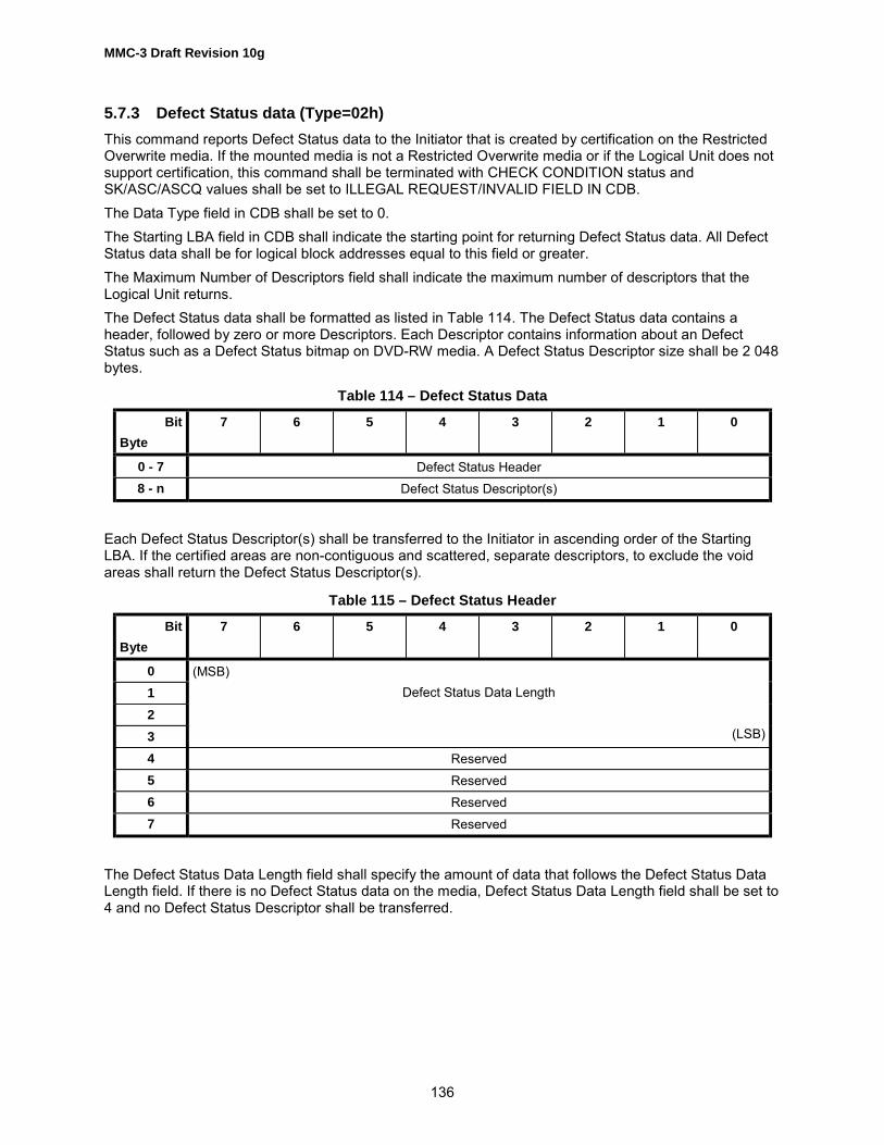
MMC-3 Draft Revision 10g
136
5.7.3 Defect Status data (Type=02h)This command reports Defect Status data to the Initiator that is created by certification on the RestrictedOverwrite media. If the mounted media is not a Restricted Overwrite media or if the Logical Unit does notsupport certification, this command shall be terminated with CHECK CONDITION status andSK/ASC/ASCQ values shall be set to ILLEGAL REQUEST/INVALID FIELD IN CDB.The Data Type field in CDB shall be set to 0.The Starting LBA field in CDB shall indicate the starting point for returning Defect Status data. All DefectStatus data shall be for logical block addresses equal to this field or greater.The Maximum Number of Descriptors field shall indicate the maximum number of descriptors that theLogical Unit returns.The Defect Status data shall be formatted as listed in Table 114. The Defect Status data contains aheader, followed by zero or more Descriptors. Each Descriptor contains information about an DefectStatus such as a Defect Status bitmap on DVD-RW media. A Defect Status Descriptor size shall be 2 048bytes.
Table 114 – Defect Status Data
BitByte
7 6 5 4 3 2 1 0
0 - 7 Defect Status Header8 - n Defect Status Descriptor(s)
Each Defect Status Descriptor(s) shall be transferred to the Initiator in ascending order of the StartingLBA. If the certified areas are non-contiguous and scattered, separate descriptors, to exclude the voidareas shall return the Defect Status Descriptor(s).
Table 115 – Defect Status Header
BitByte
7 6 5 4 3 2 1 0
0123
(MSB)Defect Status Data Length
(LSB)
4 Reserved5 Reserved6 Reserved7 Reserved
The Defect Status Data Length field shall specify the amount of data that follows the Defect Status DataLength field. If there is no Defect Status data on the media, Defect Status Data Length field shall be set to4 and no Defect Status Descriptor shall be transferred.

MMC-3 Draft Revision 10g
137
Table 116 – Defect Status Descriptor
BitByte
7 6 5 4 3 2 1 0
0123
(MSB)Start LBA
(LSB)
4567
(MSB)End LBA
(LSB)
8 Blocking Factor9 Reserved First Bit Offset
10 DS #8 DS #7 DS #6 DS #5 DS #4 DS #3 DS #2 DS #1… � � � � � � � �
2047 DS #16 304
DS #16 303
DS #16 302
DS #16 301
DS #16 300
DS #16 299
DS #16 298
DS #16 297
The Start LBA field contains the start Logical Block Address of the certified sector where the followingDefect Status (DS #n bits) starts. The returned Logical Block Address shall be the first sector of a Blockthat contains logical blocks specified by the Blocking Factor field.The End LBA field contains the end Logical Block Address of the certified sector where the followingDefect Status (DS #n bits) ends. The returned Logical Block Address shall be the last sector of a Blockthat contains logical blocks specified by the Blocking Factor field.The Blocking Factor field shall indicate the number of logical blocks per DS #m bit. In the case of DVD-RW, this filed shall be set to 16 as an ECC Block.The First Bit offset field shall indicate the start valid bit number in the byte 10. The lower bits in the byte10 are invalid. For example, if First Bit offset field contains 3, bit 3 of byte 10 has the defect status of theblock that contains the Logical block specified Start LBA field. From bit 2 to bit 0 are invalid in this case.DS #n bit contains the certification result of the block #m. When DS #n bit is set to 0, indicate that theblock has no defect and is able to read and write the block safely. When DS #n bit is set to 1, indicatesthat the block has defect and might not be able to read and write the block safely.
5.7.4 Write Speed (Type=03h)This command reports a list of possible Write Speed descriptors. If recordable media is mounted, LogicalUnit shall report the list of speeds that are available for the Blocks of the current mounted medium. If norecordable media is mounted, Logical Unit shall report the most appropriate list of speeds such as the listfor CD-R media or just maximum recording speed. Logical Unit shall report Write Speed descriptors indescending order of the Write Speed value. If the Logical Unit supports both CLV and CAV on the media,then the Logical Unit shall report all CLV descriptors first. Initiator should detect a possible Write Speeddescriptor by this command, then set the Write Speed via SET STREAMING command. To apply thisdescriptor to SET STREAMING command, the Start LBA field is set to 0, the Read Time field and theWrite Time filed are set to 1000 (1sec).
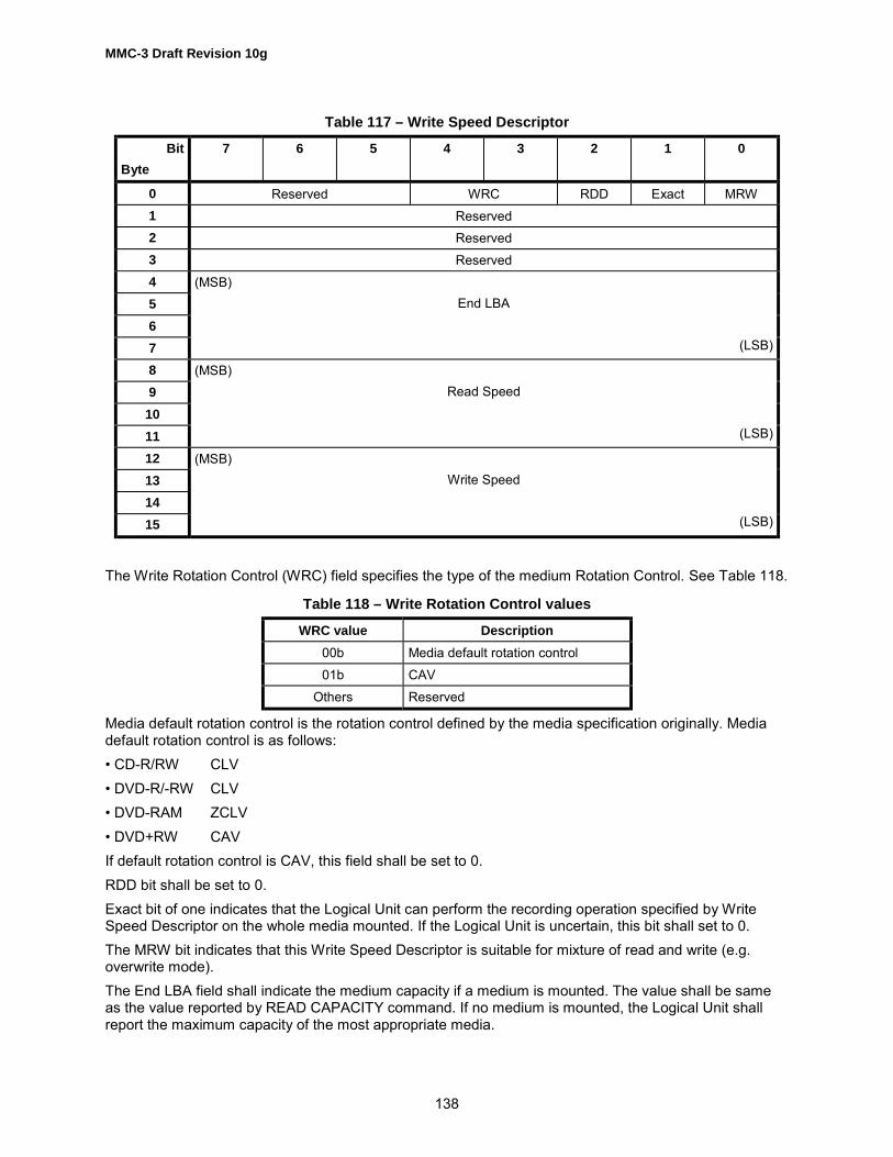
MMC-3 Draft Revision 10g
138
Table 117 – Write Speed Descriptor
BitByte
7 6 5 4 3 2 1 0
0 Reserved WRC RDD Exact MRW1 Reserved2 Reserved3 Reserved4567
(MSB)End LBA
(LSB)
89
1011
(MSB)Read Speed
(LSB)
12131415
(MSB)Write Speed
(LSB)
The Write Rotation Control (WRC) field specifies the type of the medium Rotation Control. See Table 118.
Table 118 – Write Rotation Control values
WRC value Description00b Media default rotation control01b CAV
Others Reserved
Media default rotation control is the rotation control defined by the media specification originally. Mediadefault rotation control is as follows:� CD-R/RW CLV� DVD-R/-RW CLV� DVD-RAM ZCLV� DVD+RW CAVIf default rotation control is CAV, this field shall be set to 0.RDD bit shall be set to 0.Exact bit of one indicates that the Logical Unit can perform the recording operation specified by WriteSpeed Descriptor on the whole media mounted. If the Logical Unit is uncertain, this bit shall set to 0.The MRW bit indicates that this Write Speed Descriptor is suitable for mixture of read and write (e.g.overwrite mode).The End LBA field shall indicate the medium capacity if a medium is mounted. The value shall be sameas the value reported by READ CAPACITY command. If no medium is mounted, the Logical Unit shallreport the maximum capacity of the most appropriate media.

MMC-3 Draft Revision 10g
139
The Read Speed field shall indicate the lowest read performance data of all Blocks in kilobytes persecond.The Write Speed field shall indicate the lowest write performance data of all Blocks in kilobytes persecond.Recommended error reporting is defined in Table 119.
Table 119 – Recommended errors for GET PERFORMANCE Command
Error Reference
Deferred Errors A.2General Errors Table A.2Media Access Errors Table A.3
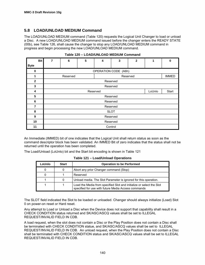
MMC-3 Draft Revision 10g
140
5.8 LOAD/UNLOAD MEDIUM CommandThe LOAD/UNLOAD MEDIUM command (Table 120) requests the Logical Unit Changer to load or unloada Disc. A new LOAD/UNLOAD MEDIUM command issued before the changer enters the READY STATE(00b), see Table 126, shall cause the changer to stop any LOAD/UNLOAD MEDIUM command inprogress and begin processing the new LOAD/UNLOAD MEDIUM command.
Table 120 – LOAD/UNLOAD MEDIUM Command
BitByte
7 6 5 4 3 2 1 0
0 OPERATION CODE (A6h)1 Reserved Reserved IMMED2 Reserved3 Reserved4 Reserved LoUnlo Start5 Reserved6 Reserved7 Reserved8 SLOT9 Reserved
10 Reserved11 Control
An Immediate (IMMED) bit of one indicates that the Logical Unit shall return status as soon as thecommand descriptor block has been validated. An IMMED Bit of zero indicates that the status shall not bereturned until the operation has been completed.The Load/Unload (LoUnlo) bit and the Start bit encoding is shown in Table 121
Table 121 – Load/Unload Operations
LoUnlo Start Operation to be Performed
0 0 Abort any prior Changer command (Stop)0 1 Reserved1 0 Unload media. The Slot Parameter is ignored for this operation.1 1 Load the Media from specified Slot and initialize or select the Slot
specified for use with future Media Access commands
The SLOT field indicated the Slot to be loaded or unloaded. Changer should always initialize (Load) Slot0 on power-on reset or Hard reset.Any attempt to Load or Unload a Disc when the Device does not support that capability shall result in aCHECK CONDITION status returned and SK/ASC/ASCQ values shall be set to ILLEGALREQUEST/INVALID FIELD IN CDB.A load request, when the slot does not contain a Disc or the Play Position does not contain a Disc shallbe terminated with CHECK CONDITION statue, and SK/ASC/ASCQ values shall be set to ILLEGALREQUEST/INVALID FIELD IN CDB. An unload request, when the Play Position does not contain a Discshall be terminated with CHECK CONDITION status and SK/ASC/ASCQ values shall be set to ILLEGALREQUEST/INVALID FIELD IN CDB.

MMC-3 Draft Revision 10g
141
A load request, when the slot does not contain a Disc shall be terminated with CHECK CONDITIONstatus and SK/ASC/ASCQ values shall be set to NOT READY/MEDIUM NOT PRESENT. When this erroris returned there are two possible actions by the CD Changer Device. If the Logical Unit reports SoftwareSlot Selection (SSS) = 1, (see Table 361), then the slot specified shall be selected for use. If the LogicalUnit reports SSS = 0 then the previously used slot shall continue to be selected for use.If the Logical Unit is capable of caching data then a delayed load of a disc into the playing position can besupported. If delayed loading of a disc into the playing position is supported, the Logical Unit shall havepreviously cached the Lead-in data from that disc. If the medium is DVD then the caching of the Lead-ininformation shall be performed. If the medium is CD then the caching of the TOC shall beperformed. If the Logical Unit has not read the Lead-in for a disc that is being loaded into the playingposition, then delayed loading shall not be performed and the disc shall be loaded into the playingposition immediately. If the loading of the Disc into the playing position is delayed, then the Logical Unitshall report that the Disc is ready, even though the Disc is not spinning and installed in the playingposition. In all cases the behavior seen by the Initiator (other than a longer subsequent media accesslatency) shall not be different between delayed and immediate loading of a discA unit attention condition shall not be generated when discs are loaded or unloaded from the playingposition.Recommended error reporting is defined in Table 122.
Table 122 – Recommended errors for LOAD/UNLOAD MEDIUM operation
Error Reference
Deferred Errors A.2General Errors Table A.2MECHANICAL POSITIONING ERROR Table A.1INVALID ELEMENT ADDRESS Table A.1MEDIA LOAD OR EJECT FAILED Table A.1

MMC-3 Draft Revision 10g
142
5.9 MECHANISM STATUS CommandThe Mechanism Status command (Table 123) requests that the Logical Unit respond with the currentstatus of the device, including any Changer Mechanism that adheres to this standard. This command isintended to provide information to the Initiator about the current operational state of the Logical Unit. TheLogical Unit takes operational direction from both the Initiator and the user. Movement of media in/out ofthe Logical Unit as well as Play operation may be due to external controls or Initiator commands. Thiscommand provides a method that allows the Initiator to know what has transpired with the changermechanism.
Table 123 – MECHANISM STATUS Command Descriptor Block
BitByte
7 6 5 4 3 2 1 0
0 Operation code (BDh)1 Reserved Reserved2 Reserved3 Reserved4 Reserved5 Reserved6 Reserved7 Reserved8 (MSB) Allocation Length9 (LSB)
10 Reserved11 Control
The Allocation Length field specifies the maximum length, in bytes, of the Mechanical Status Parameterlist, see Table 124, that shall be transferred from the Logical Unit to the Initiator. An Allocation Lengthfield of zero indicates that no data shall be transferred. This condition shall not be considered an error.The Mechanism Status Parameter list returned contains a header (Table 125) followed by zero or morefixed-length Slot Tables (Table 128). If the Logical Unit does not support the changer commands, then thenumber of slot tables returned to the Initiator shall be zero.
Table 124 – Mechanism Status Parameter List
BitByte
7 6 5 4 3 2 1 0
0-7 Mechanism Status Header8-n Slot Table(s)

MMC-3 Draft Revision 10g
143
Table 125 – Mechanism Status Header
BitByte
7 6 5 4 3 2 1 0
0 Fault Changer State Current Slot (Low order 5 bits)1 Mechanism State Door open Reserved Current Slot (High order 3 bits)2 (MSB)3 Current LBA4 (LSB)5 Number of Slots Available6 (MSB) Length of Slot Table(s)7 (LSB)
The Fault bit, bit 7, indicates that the changer failed to complete the operation reported in the ChangerState field.The Changer State field (Table 126) indicates the current state of the changer.
Table 126 – Changer State Field
Changer State Definition
0h Ready1h Load in Progress2h Unload in Progress3h Initializing
The Current Slot field (an 8-bit field) indicates the Current Slot selected. Changers compatible with abootable device specification should always initialize (Load) Slot zero on power-on reset or hard reset.This value shall only be changed when a LOAD/UNLOAD command is processed. Operations initiated bya user shall not cause this value to change. If the Logical Unit is not a changer, then this field is reserved.The Mechanism State field (Table 127) encodes the current operation of mechanism.
Table 127 – Mechanism State Field
MechanismState
Definition
0h Idle1h Playing (Audio or Data)2h Scanning3h Active with Initiator, Composite or Other
Ports in use (i.e. READ, PLAY CD, SCANduring PLAY CD)
4h-6h Reserved7h No State Information Available

MMC-3 Draft Revision 10g
144
The Slot Table response data format is defined in Table 128. Each slot shall respond with the statusdefined.The Door open bit, when set to one, indicates that the Door(s) or Tray(s) is open or the magazine is notpresent.The Current LBA value returns the location that was last used while reading or playing. Once a Read orPlay operation has been completed the value of this field may be undefined. While a Read or Play is inprogress this field shall contain the LBA of the current block being processed.The Number of Slots Available field indicates the number of slots available. The maximum number ofslots is 256.The Length of Slot Tables field specifies the length in bytes of the all the slot information that follows (e.g.for a 2 slot Logical Unit this value would be 8).
Table 128 – Slot Table Response Format
BitByte
7 6 5 4 3 2 1 0
0 DiscPresent
(Optional)
Reserved Reserved Reserved Reserved Reserved Reserved Change -Mandatory
1 Reserved CWP_V CWP2 Reserved3 Reserved
The Disc Present bit, bit 7, indicates that there is a Disc in this slot. The reporting of this information isoptional after a reset or Disc change. If this Feature is not supported, this bit shall be set to one after areset condition or when a medium has been changed. When the Logical Unit is given a load command fora slot that contains no Disc, the bit corresponding to that slot shall then contain a 0 for any followingresponse. If this bit is valid after a reset or medium change, then this capability shall be reported in theCD Capabilities and Mechanical Status Page (see Table 361).The Change bit, bit 0, indicates that the Disc in that slot has been changed since the last time the discwas loaded.CWP_V, if set to one, indicates that the Media Cartridge Write Protection (CWP) of the Cartridge in thatslot has been checked and CWP bit is valid. If set to 0, the CWP bit is invalid.CWP, if set to 1, indicates that the CWP status is active on the Cartridge. If CWP_V is set to 0, CWP bit isinvalid and shall be set to 0.Recommended error reporting is defined in Table 129.
Table 129 – Recommended errors for Mechanism Status Command
Error Reference
Deferred Errors A.2General Errors Table A.2

MMC-3 Draft Revision 10g
145
5.10 PAUSE/RESUME CommandThe PAUSE/RESUME command (Table 130) requests that the Logical Unit stop or start a playbackoperation. This command is used with PLAY AUDIO commands that are executing in immediate mode.
Table 130 – PAUSE/RESUME Command Descriptor Block
BitByte
7 6 5 4 3 2 1 0
0 OPERATION CODE (4Bh)1 Reserved Reserved2 Reserved3 Reserved4 Reserved5 Reserved6 Reserved7 Reserved8 Reserved Resume
9 Control
A Resume bit of zero causes the Logical Unit to enter the hold track state with the audio output mutedafter the current block is played. A Resume bit of one causes the Logical Unit to release the pause/scanand begin play at the block following the last block played/scanned.If an audio play operation cannot be resumed and the Resume bit is one, the command is terminated withCHECK CONDITION status and SK/ASC/ASCQ values shall be set to ILLEGAL REQUEST/COMMANDSEQUENCE ERROR. If the Resume bit is zero and an audio play operation cannot be paused, (no audioplay operation has been requested, or the requested audio play operation has been completed), thecommand is terminated with CHECK CONDITION status and SK/ASC/ASCQ values is set to ILLEGALREQUEST/COMMAND SEQUENCE ERROR.It shall not be considered an error to request a Pause when a pause is already in effect, or to request aResume when a play operation is in progress.
Table 131 – Recommended errors for PAUSE/RESUME Command
Error Reference
Deferred Errors A.2General Errors Table A.2COMMAND SEQUENCE ERROR Table A.1

MMC-3 Draft Revision 10g
146
5.11 PLAY AUDIO (10) CommandThe PLAY AUDIO (10) command (Table 132) requests that the Logical Unit begin an audio playbackoperation. The command function and the output of audio signals shall be as specified by the settings ofthe mode parameters.If any command related to audio operations is implemented then the PLAY AUDIO (10) command shallbe implemented.
Table 132 – PLAY AUDIO (10) Command
BitByte
7 6 5 4 3 2 1 0
0 Operation Code (45h)1 Reserved Reserved RelADR
2 (MSB)3 Starting Logical Block Address45 (LSB)6 Reserved7 (MSB) Play Length8 (LSB)9 Control
The RelAdr bit shall be set to zero.The Starting Logical Block Address field specifies the logical block that the audio playback operation shallbegin. PLAY AUDIO commands with a starting logical block address of FFFF FFFFh shall implementaudio play from the current location of the optics. PLAY AUDIO commands with a starting LBA addressof 0000 0000h shall begin the audio play operation at 00:02:00 MSF.The Play Length field specifies the number of contiguous logical blocks that shall be played. A PlayLength field of zero indicates that no audio operation shall occur. This condition shall not be consideredan error.If the starting address is not found, the command shall be terminated with CHECK CONDITION statusand SK/ASC/ASCQ values shall be set to ILLEGAL REQUEST/LOGICAL BLOCK ADDRESS OUT OFRANGE . If the address is not within an audio track, the command shall be terminated with CHECKCONDITION status and SK/ASC/ASCQ values shall be set to ILLEGAL REQUEST/ILLEGAL MODE FORTHIS TRACK .If the logical block address requested is not within an audio track and the Play Length is non-zero, thecommand shall be terminated with CHECK CONDITION status and SK/ASC/ASCQ values shall be set toILLEGAL REQUEST/ILLEGAL MODE FOR THIS TRACK.If the CD Sub-channel mode type (data vs. audio) is other than audio or changes within the transferlength the command shall be terminated with CHECK CONDITION status and SK/ASC/ASCQ valuesshall be set to ILLEGAL REQUEST/END OF USER AREA ENCOUNTERED ON THIS TRACK.
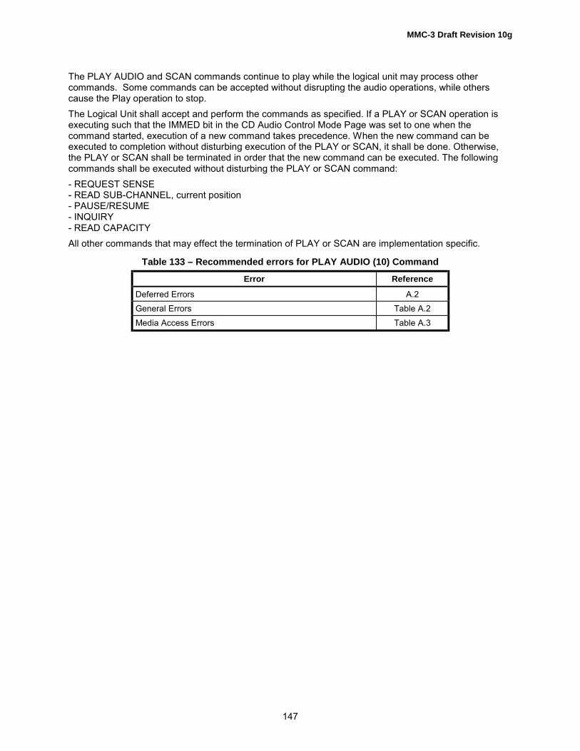
MMC-3 Draft Revision 10g
147
The PLAY AUDIO and SCAN commands continue to play while the logical unit may process othercommands. Some commands can be accepted without disrupting the audio operations, while otherscause the Play operation to stop.The Logical Unit shall accept and perform the commands as specified. If a PLAY or SCAN operation isexecuting such that the IMMED bit in the CD Audio Control Mode Page was set to one when thecommand started, execution of a new command takes precedence. When the new command can beexecuted to completion without disturbing execution of the PLAY or SCAN, it shall be done. Otherwise,the PLAY or SCAN shall be terminated in order that the new command can be executed. The followingcommands shall be executed without disturbing the PLAY or SCAN command:- REQUEST SENSE- READ SUB-CHANNEL, current position- PAUSE/RESUME- INQUIRY- READ CAPACITYAll other commands that may effect the termination of PLAY or SCAN are implementation specific.
Table 133 – Recommended errors for PLAY AUDIO (10) Command
Error Reference
Deferred Errors A.2General Errors Table A.2Media Access Errors Table A.3

MMC-3 Draft Revision 10g
148
5.12 PLAY AUDIO (12) CommandThe PLAY AUDIO (12) command (Table 134) requests that the Logical Unit begin an audio playbackoperation. The command function and the output of audio signals shall be as specified by the settings ofthe mode parameters, including the SOTC bit.
Table 134 – PLAY AUDIO (12) Command Descriptor Block
BitByte
7 6 5 4 3 2 1 0
0 OPERATION CODE (A5h)1 Reserved Reserved RelADR
2 (MSB)3 Logical Block Address45 (LSB)6 (MSB)7 Play Length89 (LSB)
10 Reserved11 Control
See PLAY AUDIO (10) command for bit and field description in the CDB.Recommended error reporting is defined in Table 135.
Table 135 – Recommended errors for PLAY AUDIO(12) Command
Error Reference
Deferred Errors A.2General Errors Table A.2Media Access Errors Table A.3
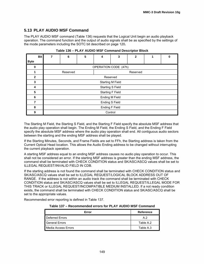
MMC-3 Draft Revision 10g
149
5.13 PLAY AUDIO MSF CommandThe PLAY AUDIO MSF command (Table 136) requests that the Logical Unit begin an audio playbackoperation. The command function and the output of audio signals shall be as specified by the settings ofthe mode parameters including the SOTC bit described on page 120.
Table 136 – PLAY AUDIO MSF Command Descriptor Block
BitByte
7 6 5 4 3 2 1 0
0 OPERATION CODE (47h)1 Reserved Reserved2 Reserved3 Starting M Field4 Starting S Field5 Starting F Field6 Ending M Field7 Ending S Field8 Ending F Field9 Control
The Starting M Field, the Starting S Field, and the Starting F Field specify the absolute MSF address thatthe audio play operation shall begin. The Ending M Field, the Ending S Field, and the Ending F Fieldspecify the absolute MSF address where the audio play operation shall end. All contiguous audio sectorsbetween the starting and the ending MSF address shall be played.If the Starting Minutes, Seconds, and Frame Fields are set to FFh, the Starting address is taken from theCurrent Optical Head location. This allows the Audio Ending address to be changed without interruptingthe current playback operation.A starting MSF address equal to an ending MSF address causes no audio play operation to occur. Thisshall not be considered an error. If the starting MSF address is greater than the ending MSF address, thecommand shall be terminated with CHECK CONDITION status and SK/ASC/ASCQ values shall be set toILLEGAL REQUEST/INVALID FIELD IN CDB.If the starting address is not found the command shall be terminated with CHECK CONDITION status andSK/ASC/ASCQ values shall be set to ILLEGAL REQUEST/LOGICAL BLOCK ADDRESS OUT OFRANGE. If the address is not within an audio track the command shall be terminated with CHECKCONDITION status and SK/ASC/ASCQ values shall be set to ILLEGAL REQUEST/ILLEGAL MODE FORTHIS TRACK or ILLEGAL REQUEST/INCOMPATIBLE MEDIUM INSTALLED. If a not ready conditionexists, the command shall be terminated with CHECK CONDITION status and SK/ASC/ASCQ shall beset to the appropriate values.Recommended error reporting is defined in Table 137.
Table 137 – Recommended errors for PLAY AUDIO MSF Command
Error Reference
Deferred Errors A.2General Errors Table A.2Media Access Errors Table A.3

MMC-3 Draft Revision 10g
150
5.14 READ (12) CommandThe READ (12) command (Table 216) requests that the Logical Unit transfer data to the Initiator. Themost recent data value written in the addressed logical block shall be returned. Any read by the Initiator toa Logical Block with a Title Key present in the sector (DVD-ROM Media Only), when the AuthenticationSuccess Flag (ASF) is set to zero shall be blocked. The command shall be terminated with CHECKCONDITION status and SK/ASC/ASCQ values shall be set to ILLEGAL REQUEST/READ OFSCRAMBLED SECTOR WITHOUT AUTHENTICATION.
Table 138 – READ (12) Command Descriptor Block
BitByte
7 6 5 4 3 2 1 0
0 OPERATION CODE (A8h)1 Reserved DPO (0) FUA Reserved RELADR2345
(MSB)Logical Block Address
(LSB)
6789
(MSB)Transfer Length
(LSB)
10 Streaming Reserved11 Control
The Disable Page Out (DPO) bit is not used by Logical Units and shall be set to zero. A DPO bit of zeroindicates the retention priority field in the Cache Page shall determine the priority, if supported. All otheraspects of the algorithm implementing the cache memory replacement strategy are vender specific.A Force Unit Access (FUA) bit of one indicates that the Logical Unit shall access the media in performingthe command. Read commands shall access the specified logical blocks from the media (i.e. the data isnot directly retrieved from the cache). In the case where the cache contains a more recent version of alogical block than the media, the logical block shall first be written to the media.An FUA bit of zero indicates that the Logical Unit may satisfy the command by accessing the cachememory. For read operations, any logical blocks that are contained in the cache memory may betransferred to the Initiator directly from the cache memory.The Transfer Length field specifies the number of contiguous logical blocks of data that shall betransferred. A Transfer Length of zero indicates that no logical blocks shall be transferred. This conditionshall not be considered an error. Any other value indicates the number of logical blocks that shall betransferred.The Streaming bit of one specifies that the Stream playback operation shall be used for the command(see 4.6.2). The Streaming bit of zero specifies that the conventional READ operation shall be used forthe command. If the Streaming bit is set to one, the cache control Mode parameter may be ignored.When the Streaming bit is set to one, the FUA bit shall be set to zero. If both the Streaming bit and theFUA bit is set to one, the Logical Unit shall terminate the command with CHECK CONDITION status andSK/ASC/ASCQ values shall be set to ILLEGAL REQUEST/INVALID FIELD IN CDB.

MMC-3 Draft Revision 10g
151
Recommended error reporting is defined in Table 217.
Table 139 – Recommended errors for READ (12) Command
Error Reference
Deferred Errors A.2General Errors Table A.2Media Access Errors Table A.3

MMC-3 Draft Revision 10g
152
5.15 READ BUFFER CAPACITY CommandThe READ BUFFER CAPACITY command (Table 140) checks the total length of buffer and the length ofblank area.
Table 140 – READ BUFFER CAPACITY Command Descriptor Block
BitByte
7 6 5 4 3 2 1 0
0 Operation Code (5Ch)1 Reserved Reserved BLOCK2 Reserved3 Reserved4 Reserved5 Reserved6 Reserved7 (MSB) Allocation Length8 (LSB)9 Control
The Logical Unit reports the length of the buffer during Session at Once Recording or Track at OnceRecording or Disc at once recording.The BLOCK bit, if set to one, indicates that the Initiator is requesting buffer data returned in blocks.An Allocation Length of zero is not an error.The READ BUFFER CAPACITY data (Table 141) is sent in response to this command.
Table 141 – READ BUFFER CAPACITY data when BLOCK bit of CDB = 0
BitByte
7 6 5 4 3 2 1 0
0 (MSB) Data Length1 (LSB)2 Reserved3 Reserved4 (MSB)5 Length of the Buffer67 (LSB)8 (MSB)9 Blank Length of Buffer
1011 (LSB)
The Data Length field defines the number of data bytes to be transferred by the Logical Unit. The DataLength value does not include the Data Length field itself.

MMC-3 Draft Revision 10g
153
The Length of Buffer indicates the whole capacity of the buffer in bytes.The Blank Length of Buffer indicates the length of unused area of the buffer in bytes.If the READ BUFFER CAPACITY command is issued in a condition except Session at Once recording orTrack at Once recording, or Disc at Once recording, the Blank Length of Buffer field may be invalid.
Table 142 – READ BUFFER CAPACITY data when BLOCK bit of CDB = 1
BitByte
7 6 5 4 3 2 1 0
0 (MSB) Data Length1 (LSB)2 Reserved3 Reserved BLOCK4 Reserved5 Reserved6 Reserved7 Reserved8 (MSB)9 Available Length of Buffer
1011 (LSB)
The Data Length field indicates the number of data bytes to be transferred by the Logical Unit. The DataLength value does not include the Data Length field itself.The Block bit, if set to one, indicates the current number of blocks is being returned. If set to zero, theInitiator shall assume legacy behavior of number of bytes being returned.The Available Length of Buffer field indicates the number of blocks of buffer currently available to bewritten to by the Initiator. The Logical Unit shall be able to immediately accept at least this much data forwriting. If the Available Length of Buffer becomes zero, the Logical Unit shall begin writing. The LogicalUnit may begin writing before the Available Length of Buffer reaches zero.
Table 143 – Recommended errors for READ BUFFER CAPACITY Command
Error Reference
Deferred Errors A.2General Errors Table A.2

MMC-3 Draft Revision 10g
154
5.16 READ CAPACITY CommandThe READ CAPACITY command (Table 144) provides a means for the Initiator to request informationregarding the capacity of the Logical Unit. This command shall not report the correct capacity of therecorded data for CD-R, CD-RW and DVD-R/-RW media that does not have a Lead-out in the lastSession or last Border-out. For CD-ROM, the returned logical block address is modified to allow returninga possibly inexact value (but one with a known error bound) based on the Table of Contents data.
Table 144 – READ CAPACITY Command Descriptor Block
BitByte
7 6 5 4 3 2 1 0
0 OPERATION CODE (25h)1 RESERVED Reserved RelAdr
2 (MSB)3 Logical Block Address45 (LSB)6 Reserved7 Reserved8 Reserved PMI9 Control
The RelAdr, PMI bits, and Logical Block Address field shall be set to zero for multimedia Logical Units.Eight bytes of READ CAPACITY response data (Table 145) shall be returned in response to thecommand.
Table 145 – READ CAPACITY Response Data format
BitByte
7 6 5 4 3 2 1 0
0 (MSB)... Logical Block Address3 (LSB)4 (MSB)... Block Length in Bytes = 2 048d7 (LSB)
The returned Logical Block Address shall be the last sector in the last complete session.The Block Length shall be reported, in bytes, as 2 048d. A block length of 512 is obsolete.For CD media other than MRW format, the last logical block shall be determined by converting the lastrecorded Lead-out to an LBA and subtracting one. If the resulting address points to a run out block(because the session was recorded with packets or track at once in data mode), the Logical Unit shallsubtract 2 from the LBA to point to the actual last user data block. If no complete session exists on themedium, this field shall be set to zero.

MMC-3 Draft Revision 10g
155
If the mounted medium is a DVD+RW disc, then the value returned is the LBA that represents the lastblock of the user space. If a background format is in progress, then the LBA shall be reported as if theformat had completed.If the mounted medium has the MRW format, then the LBA value returned is the LBA that represents thelast block of the LBA space selected in the MRW Mode Page. If a background format is in progress, thenthe LBA shall be reported as if the format had completed.Recommended error reporting is defined in Table 146.
Table 146 – Recommended errors for READ CAPACITY Command
Error Reference
Deferred Errors A.2General Errors Table A.2Media Access Errors Table A.3

MMC-3 Draft Revision 10g
156
5.17 READ CD CommandThe READ CD command (Table 147) provides a single standard, universal way of accessing CD data.This command is generic to all types of CD data formats.This command returns any of the defined CD data streams, including the headers, EDC, ECC, user dataand CD-DA data. Each type of data is enabled via the fields in the READ CD command descriptor block.These fields, (byte 9) indicate the information from the CD is to be returned in the data stream. If a bit iscleared, then that particular information is not returned. If all the fields contain zero then no information isreturned. This condition shall not be considered an error.
Table 147 – READ CD Command Descriptor Block
BitByte
7 6 5 4 3 2 1 0
0 OPERATION CODE (BEh)1 RESERVED Expected Sector Type Reserved RelADR
2345
(MSB)Starting Logical Block Address
(LSB)
678
(MSB)Transfer Length
(LSB)
9 SYNC Header Codes User Data EDC &ECC
Error Field Reserved
10 Reserved Sub-channel Selection Bits11 Control
The Expected Sector Type field (Table 148) is used as a filter or mask to select the types of data formatinformation returned to the Initiator. A transfer operation is terminated as soon as data is encounteredthat does not match one of those specified in the sector type field of the command. If the requested datais not of the type/types requested, the command shall be terminated with a CHECK CONDITION statusand SK/ASC/ASCQ values shall be set to ILLEGAL REQUEST/ILLEGAL MODE FOR THIS TRACK. Thesector/sectors that do not match shall not be transferred to the Initiator.

MMC-3 Draft Revision 10g
157
Table 148 – Expected Sector type field bit definitions
SectorType
Definition Description
000b All types(mandatory)
No checking of the data type is performed. The Logical Unit shall always terminate acommand at the sector where a transition between CD-ROM and CD-DA data occurs.
001b CD-DA(optional)
Only IEC 908:1987 (CD-DA) sectors shall be returned. If any other format is encountered,the command shall be terminated with CHECK CONDITION status.
010b Mode 1(mandatory)
Only Yellow Book (see Table 350) sectors with a user data field of 2 048 bytes shall bereturned. All other data formats encountered return an error.
011b Mode 2formless(mandatory)
Only Yellow Book (see Table 350) sectors with the expanded user data field (2 336 bytes)shall be returned. If any other format is encountered, the command shall be terminated withCHECK CONDITION status.
100b Mode 2form 1(mandatory)
Only sectors (see Table 350) that have a user data field of 2 048 bytes shall be returned. Ifany other format is encountered, the command shall be terminated with CHECKCONDITION status.
101b Mode 2form 2(mandatory)
Only sectors (see Table 350) that have a user data field of 2 324 shall be returned. If anyother format is encountered, the command shall be terminated with CHECK CONDITIONstatus.NOTE: 4 spare bytes are included making the total data length returned 2 328 bytes/sector.
110b-111b
Reserved
The RELADR bit shall be set to zero.The Starting Logical Block Address field specifies the logical block that the read operation shall begin.The Transfer Length field specifies the number of contiguous logical blocks of data that shall betransferred. A Transfer Length field of zero indicates that no transfer of data shall occur. This conditionshall not be considered an error.The Sync bit, set to one, indicates that the Sync field from the sector shall be included in the data stream.The Sync bit, set to zero indicates the Sync field shall not be included in the data stream.The Header Code field (Table 149) is encoded to select Header/Sub-header information that should beincluded in the returned data stream.
Table 149 – Header Code field definition
HeaderCode
Definition Description
00b none No header information shall be returned.01b header only Only the four-byte header shall be returned in the data stream.10b sub-header only Only the mode 2 form 1 or form 2 sub-header shall be returned.11b All headers Both header and sub-header shall be returned.
The User data bit, when set to one, indicates that the user data part of a CD sector shall be returned inthe data stream. When set to zero, user data shall not be returned to the Initiator. The setting of the ModeSelect Block Size does not apply to this command. If the current track is an audio track, then audio datashall be returned. Otherwise, the normal user data shall be returned.The EDC and ECC bit, when set to one, indicates that the EDC and ECC (L-EC) field shall be included inthe data stream. For Mode 1 CD format, this includes the 8 bytes of pad data.

MMC-3 Draft Revision 10g
158
The Error field (see Table 150) is an encoded field that indicates that if any of the C2 and/or Block errordata is included in the data stream.If the Logical Unit does not support the C2 pointers, and the Error field is not zero, the C2 data field shallbe zero filled.
Table 150 – READ CD, Error field definition
Error Field
Definition Description
00b none No error information is returned.01b C2 error
block dataThe C2 error, Pointer bits (2 352 bits or 294 bytes) is included in the data stream. There isone bit for each byte in error in the sector (2 352 total). The bit ordering is from the mostsignificant bit to the least significant bit in each byte. The first bytes in the sector are the firstbits/bytes in the data stream.
10b C2 andBlock ErrorBits
Both the C2 error bits (2 352 bits/294 bytes) and the Block Error Byte are included in thedata stream. The Block Error Byte is the logical or of all the C2 Error bit bytes. The ErrorByte shall be padded with a byte (undefined) to ensure an even number of bytes in the datastream. The Block error byte shall be first in the data stream followed by the pad byte.
11b Reserved Reserved for future enhancement.
The Sub-channel data selection field (see Table 151) indicates that CD Sub-channel information is to beincluded in the data stream. This may be the Q information and/or the �Raw� Sub-channel information. Ifthe field is set to a nonzero value, then that Sub-channel data shall be included in the data stream to theInitiator.
Table 151 – READ CD, Sub-channel Data Selection Field definition
Sub-channel dataselection value
Definition Description Type
000b No Sub-channel data No Sub-channel data shall be returned. Mandatory001b RAW RAW P-W Sub-channel data shall be
returned.Optional
010b Q Q data shall be transferred. Optional011b Reserved100b P-W R-W data shall be transferred. Optional
101b-111b Reserved
In the case of R-W the Logical Unit may return the data de-interleaved and error corrected, RAW orpadded with zeroes depending on the R-W supported and R-W de-interleaved and error corrected bits inthe CD capabilities and Mechanism status page. In the case of RAW the Logical Unit returns the P-WSub-channel data that is not de-interleaved. See Table 155 and for P-W data formats.If the Starting Logical Block Address is set to FFFF FFFFh, Sub-channel data is the only informationrequested, and there is currently a PLAY AUDIO command in process, the actual address used is fromthe current location of the audio play.
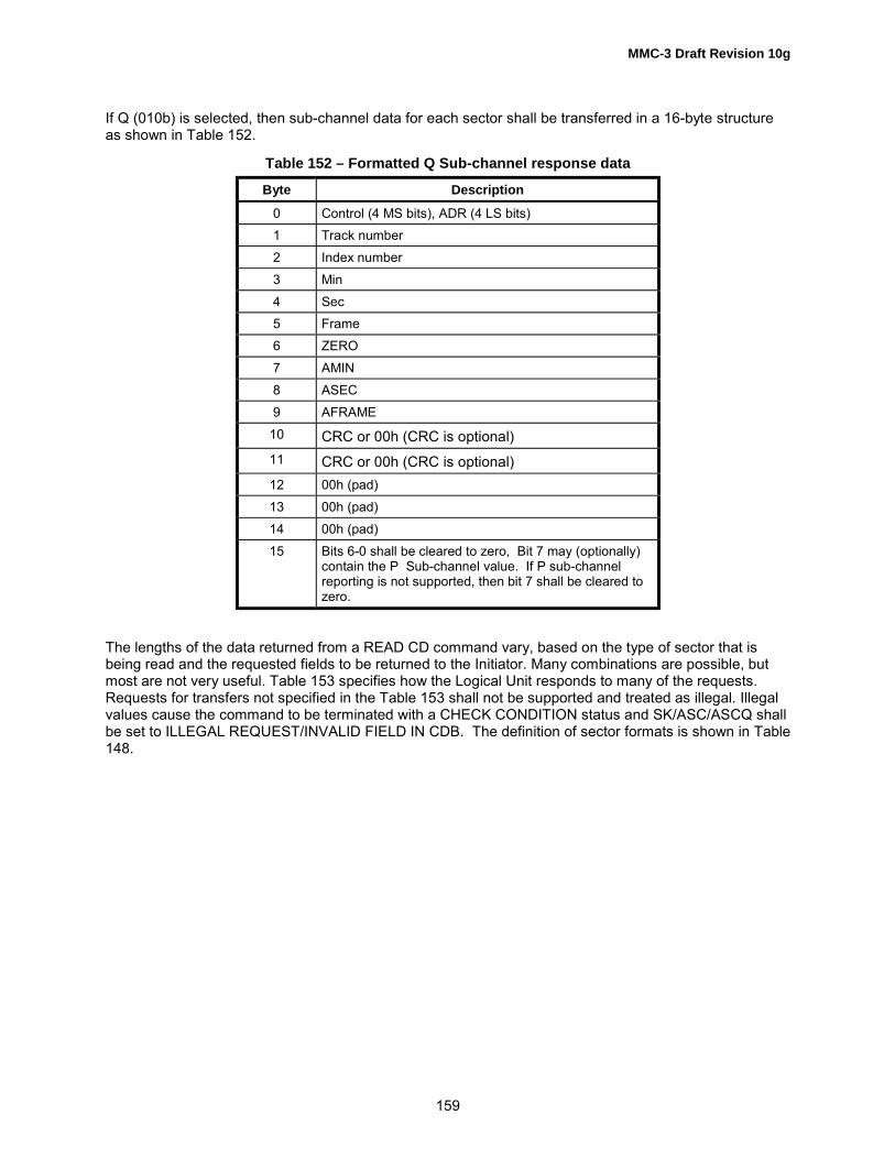
MMC-3 Draft Revision 10g
159
If Q (010b) is selected, then sub-channel data for each sector shall be transferred in a 16-byte structureas shown in Table 152.
Table 152 – Formatted Q Sub-channel response data
Byte Description
0 Control (4 MS bits), ADR (4 LS bits)1 Track number2 Index number3 Min4 Sec5 Frame6 ZERO7 AMIN8 ASEC9 AFRAME
10 CRC or 00h (CRC is optional)11 CRC or 00h (CRC is optional)12 00h (pad)13 00h (pad)14 00h (pad)15 Bits 6-0 shall be cleared to zero, Bit 7 may (optionally)
contain the P Sub-channel value. If P sub-channelreporting is not supported, then bit 7 shall be cleared tozero.
The lengths of the data returned from a READ CD command vary, based on the type of sector that isbeing read and the requested fields to be returned to the Initiator. Many combinations are possible, butmost are not very useful. Table 153 specifies how the Logical Unit responds to many of the requests.Requests for transfers not specified in the Table 153 shall not be supported and treated as illegal. Illegalvalues cause the command to be terminated with a CHECK CONDITION status and SK/ASC/ASCQ shallbe set to ILLEGAL REQUEST/INVALID FIELD IN CDB. The definition of sector formats is shown in Table148.
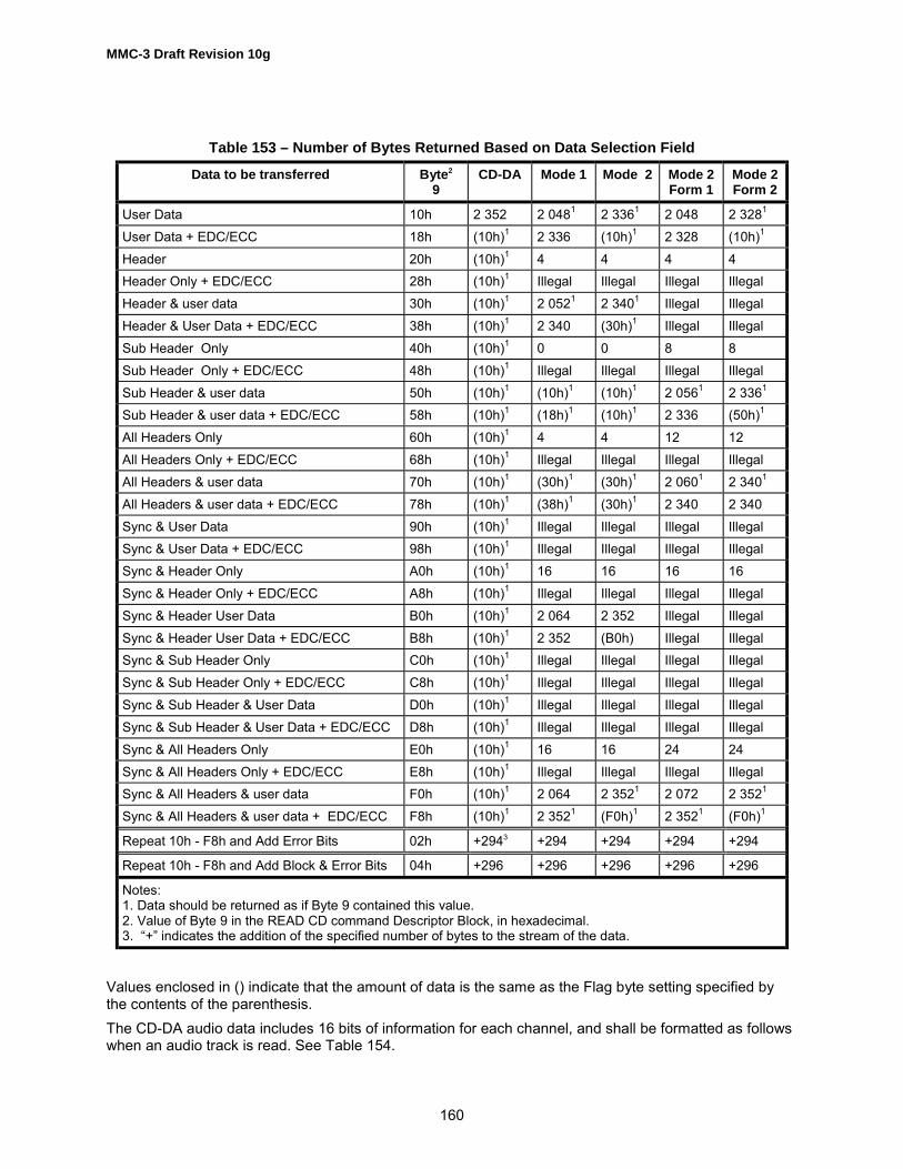
MMC-3 Draft Revision 10g
160
Table 153 – Number of Bytes Returned Based on Data Selection Field
Data to be transferred Byte2
9CD-DA Mode 1 Mode 2 Mode 2
Form 1Mode 2Form 2
User Data 10h 2 352 2 0481 2 3361 2 048 2 3281
User Data + EDC/ECC 18h (10h)1 2 336 (10h)1 2 328 (10h)1
Header 20h (10h)1 4 4 4 4Header Only + EDC/ECC 28h (10h)1 Illegal Illegal Illegal IllegalHeader & user data 30h (10h)1 2 0521 2 3401 Illegal IllegalHeader & User Data + EDC/ECC 38h (10h)1 2 340 (30h)1 Illegal IllegalSub Header Only 40h (10h)1 0 0 8 8Sub Header Only + EDC/ECC 48h (10h)1 Illegal Illegal Illegal IllegalSub Header & user data 50h (10h)1 (10h)1 (10h)1 2 0561 2 3361
Sub Header & user data + EDC/ECC 58h (10h)1 (18h)1 (10h)1 2 336 (50h)1
All Headers Only 60h (10h)1 4 4 12 12All Headers Only + EDC/ECC 68h (10h)1 Illegal Illegal Illegal IllegalAll Headers & user data 70h (10h)1 (30h)1 (30h)1 2 0601 2 3401
All Headers & user data + EDC/ECC 78h (10h)1 (38h)1 (30h)1 2 340 2 340Sync & User Data 90h (10h)1 Illegal Illegal Illegal IllegalSync & User Data + EDC/ECC 98h (10h)1 Illegal Illegal Illegal IllegalSync & Header Only A0h (10h)1 16 16 16 16Sync & Header Only + EDC/ECC A8h (10h)1 Illegal Illegal Illegal IllegalSync & Header User Data B0h (10h)1 2 064 2 352 Illegal IllegalSync & Header User Data + EDC/ECC B8h (10h)1 2 352 (B0h) Illegal IllegalSync & Sub Header Only C0h (10h)1 Illegal Illegal Illegal IllegalSync & Sub Header Only + EDC/ECC C8h (10h)1 Illegal Illegal Illegal IllegalSync & Sub Header & User Data D0h (10h)1 Illegal Illegal Illegal IllegalSync & Sub Header & User Data + EDC/ECC D8h (10h)1 Illegal Illegal Illegal IllegalSync & All Headers Only E0h (10h)1 16 16 24 24Sync & All Headers Only + EDC/ECC E8h (10h)1 Illegal Illegal Illegal IllegalSync & All Headers & user data F0h (10h)1 2 064 2 3521 2 072 2 3521
Sync & All Headers & user data + EDC/ECC F8h (10h)1 2 3521 (F0h)1 2 3521 (F0h)1
Repeat 10h - F8h and Add Error Bits 02h +2943 +294 +294 +294 +294
Repeat 10h - F8h and Add Block & Error Bits 04h +296 +296 +296 +296 +296
Notes:1. Data should be returned as if Byte 9 contained this value.2. Value of Byte 9 in the READ CD command Descriptor Block, in hexadecimal.3. �+� indicates the addition of the specified number of bytes to the stream of the data.
Values enclosed in () indicate that the amount of data is the same as the Flag byte setting specified bythe contents of the parenthesis.The CD-DA audio data includes 16 bits of information for each channel, and shall be formatted as followswhen an audio track is read. See Table 154.

MMC-3 Draft Revision 10g
161
Table 154 – CD-DA (Digital Audio) Data Block Format
BitByte
7 6 5 4 3 2 1 0
0 Left Channel (Lower Byte) (LSB)1 (MSB) Left Channel (Upper Byte)2 Right Channel (Lower Byte) (LSB)3 (MSB) Right Channel (Upper Byte)… �… �
2348 Left Channel (Lower Byte) (LSB)2349 (MSB) Left Channel (Upper Byte)2350 Right Channel (Lower Byte) (LSB)2351 (MSB) Right Channel (Upper Byte)
If the CD Logical Unit does not support the CD-DA Stream-Is-Accurate capability (See Table 361), thenthe digital audio data shall be read as a continuous stream. If the Logical Unit stops while streaming, anon-recoverable error shall be generated. The next read command shall be terminated with CHECKCONDITION status and SK/ASC/ASCQ values shall be set to ABORTED COMMAND/READ ERROR -LOSS OF STREAMING. This is due to the 1-second uncertainty of the address. (i.e. there is no header inCD-DA data). Reissuing the command may not return exactly the same data as the previous try. Whenthe Logical Unit supports the stream accurate capability, no error shall be generated, only some timedelay for rotational latency.The format for P-W raw data is described in Table 155.
Table 155 – P-W RAW data format
BitByte
7 6 5 4 3 2 1 0
0 P-W (0)1 P-W (1)... …95 P-W (95)

MMC-3 Draft Revision 10g
162
R-W raw data (bits 0-5, Table 156) is returned in the format and order found on the media. It is theresponsibility of the initiator to de-interleave and perform error detection and correction on the RAW datato make it usable to higher level applications.
Table 156 – P-W Data de-interleaved and error corrected
BitByte
7 6 5 4 3 2 1 0
0 P Q PACK (0)1 P Q PACK (1)... …23 P Q PACK (23)24 P Q PACK (0)25 P Q PACK (1)... ...47 P Q PACK (23)48 P Q PACK (0)49 P Q PACK (1)... ...71 P Q PACK (23)72 P Q PACK (0)73 P Q PACK (1)... ...95 P Q PACK (23)
Logical Units that cannot return P or Q code with PACK data shall return undefined data in theunsupported P or Q bits. Each PACK is generated after 2 contiguous Sub Channel data framesconsisting of 24 bytes with 6 bits of PACK data per byte. Each 96 byte Packet consists of 4 Packs of 24bytes each.The basic RAW format is shown in Figure 42 below. The data is synchronized with the Sub-channel syncpatterns S0 and S1. Each group of 6 bits (R-W) is called a �symbol.� The symbol following the Sub-channel patterns S0 and S1, is the first symbol of the first pack in a packet.

MMC-3 Draft Revision 10g
163
5.17.1 Description of Sub-channels R-W
Figure 42 – Read CD Sub-channel, R-W (100b)
12Q 4 pad
P Q R-W
P Q R-W
Sync
Sync
PACKET PACKET
98 Bytes
96 Bytes (RAW)
96 six-bit symbols
4 Groups of 24 words
PACK PACK PACK PACK
Sync
2 24 24 24 24
4 Groups of 24 words
PACK PACK PACK PACK
Sync
2 24 24 24 24
Mode & Item
EDC/ECCParity P0-P3
1 1
EDC/ECCParity Q0/1
2
User Data
16 4
Instruction
Formatted Q
Build a Data Packet *
* the technique for building a data packet is beyond the scope of this standard.

MMC-3 Draft Revision 10g
164
To guard the data in the sub-coding channels R-W, a (24, 20) Reed-Solomon Error Correction Code isused. To improve the burst error correction capability, eight way interleaving is added to this errorcorrection system.The first two symbols in a pack have additional protection with a (4, 2) Reed Solomon Error CorrectionCode. The first symbol of a pack contains a mode-switch of 3 bits and a 3 bit subdivision of mode, called�item.� The defined mode-item combinations are listed in Table 157.
Table 157 – Sub-channel R-W: Allowed mode/item combinations
Mode Item Description
000b 000b The Zero mode001b 000b The LINE GRAPHICS mode
001b The TV GRAPHICS mode111b 000b The USER mode
All others Reserved for future use
The R-W information is returned as part of the �raw� Sub-channel data. The lower 6 bits of each of thebytes contain the R-W data. This data follows the format shown in Figure 42. If the Q information needs tobe taken from the raw data then it shall not be interleaved.
5.17.2 CD-TEXTWhen the Starting Logical Block Address is set to F000 0000h and P-W raw data is selected, the LogicalUnit returns P-W raw data from the Lead-in area. If there is no data recorded in the Lead-in area, thecommand shall be terminated with CHECK CONDITION status and set the values of SK/ASC/ASCQ toILLEGAL REQUEST/ILLEGAL MODE FOR THIS TRACK or ILLEGAL REQUEST/INCOMPATIBLEMEDIUM INSTALLED.If the Starting Logical Block Address is set to FFFF FFFFh after the above command, the Sub-channeldata shall be returned from the current location within the Lead-in area. It is the responsibility of theinitiator to convert this data to CD-TEXT format without losing streaming.Recommended error reporting is defined in Table 158.
Table 158 – Recommended errors for READ CD Command
Error Reference
Deferred Errors A.2General Errors Table A.2Media Access Errors Table A.3READ ERROR - LOSS OF STREAMING Table A.1

MMC-3 Draft Revision 10g
165
5.18 READ CD MSF CommandThe READ CD MSF command described in Table 159 provides a single standard command format foraccessing CD data via MSF addressing. This command is generic to all types of CD data formats.This command returns any of the defined CD data streams, including the headers, EDC, ECC, user dataand CD-DA data. Each type of data is enabled via the fields in the READ CD MSF command descriptorblock. These fields indicate the information from the CD is to be returned in the data stream. If the bit iscleared, then that particular information is not returned. If all the fields contain zero then no information isreturned. This condition shall not be considered an error.
Table 159 – READ CD MSF Command Descriptor Block
BitByte
7 6 5 4 3 2 1 0
0 OPERATION CODE (B9h)1 Reserved Sector Type Reserved2 Reserved3 Starting M Field4 Starting S Field5 Starting F Field6 Ending M Field7 Ending S Field8 Ending F Field9 SYNC Header Codes User Data EDC &
ECCError Fields Reserved
10 Reserved Sub-channel Selection Bits11 Control
The Starting M field, the Starting S field, and the Starting F field specify the absolute MSF address wherethe Read operation shall begin. The Starting MSF shall not begin earlier than the start of the first lead-inon the disc.The Ending M field, the Ending S field, and the Ending F field specify the absolute MSF address wherethe Read operation shall end. The Ending MSF shall not end later than 1.5 minutes beyond themaximum start address of the last lead-out of the disc.All contiguous sectors between the starting and ending MSF addresses shall be read.
Implementers Note: Reading across some CD structural boundaries may result in data errors.
If the starting address is not found, the command shall be terminated with CHECK CONDITION statusand set the values of SK/ASC/ASCQ to ILLEGAL REQUEST/ INVALID FIELD IN CDB.A starting MSF address equal to an ending MSF address prevents a read operation. This shall not beconsidered an error. If the starting MSF address is greater than the ending MSF address, the commandshall be terminated with CHECK CONDITION status and set the values of SK/ASC/ASCQ to ILLEGALREQUEST/ INVALID FIELD IN CDB.For descriptions of Sector Type field see Table 148.For a description of all fields in byte 9, and Sub-channel Selection Bits (byte 10), see sub-clause 5.17

MMC-3 Draft Revision 10g
166
Recommended error reporting is defined in Table 160.
Table 160 – Recommended errors for READ CD MSF Command
Error Reference
Deferred Errors A.2General Errors Table A.2Media Access Errors Table A.3READ ERROR - LOSS OF STREAMING Table A.1

MMC-3 Draft Revision 10g
167
5.19 READ DISC INFORMATION CommandThe READ DISC INFORMATION command (Table 161) provides information about all discs. Theparameters returned by the Logical Unit are specific to the media that is currently installed in the LogicalUnit. In the case of a DVD-ROM Logical Unit, the disc information returned may be for the last closedSession. In the case of media that does not have logical Tracks, the number of Tracks and Sessions isconsidered one. If this command is required by an implemented Feature, the command shall alwaysfunction, even if that Feature�s Current bit becomes zero.
Table 161 – READ DISC INFORMATION Command
BitByte
7 6 5 4 3 2 1 0
0 Operation Code (51h)1 Reserved2 Reserved3 Reserved4 Reserved5 Reserved6 Reserved7 (MSB) Allocation Length8 (LSB)9 Control Byte
The number of Disc Information bytes returned is limited by the Allocation Length parameter of theCommand Packet. An Allocation Length of zero shall not be considered an error. If the Allocation Lengthis greater than the amount of available Disc Information Data (Table 162), only the available data istransferred.If a field or bit is not applicable to the installed medium, the default parameters in the Write ParametersPage shall be returned in the corresponding field.

MMC-3 Draft Revision 10g
168
Table 162 – Disc Information Block
BitByte
7 6 5 4 3 2 1 0
0 (MSB) Disc Information Length1 (LSB)2 Reserved Erasable State of last Session Disc Status3 Number of First Track on Disc4 Number of Sessions (Least Significant Byte)5 First Track Number in Last Session (Least Significant Byte)6 Last Track Number in Last Session (Least Significant Byte)7 DID_V DBC_V URU Reserved DBit BG Format Status8 Disc Type9 Number of Sessions (Most Significant Byte)
10 First Track Number in Last Session (Most Significant Byte)11 Last Track Number in Last Session (Most Significant Byte)12 (MSB)13 Disc14 Identification15 (LSB)16 (MSB)17 Last Session Lead-in Start Time18 HMSF19 (LSB)20 (MSB)21 Last Possible Start Time for Start of Lead-out22 HMSF23 (LSB)24 (MSB)... Disc Bar Code31 (LSB)32 Reserved33 Number of OPC Table Entries
34 - n OPC Table Entries

MMC-3 Draft Revision 10g
169
The Disc Information Length is the number of bytes available in both the recording information area andthe appended OPC table. Disc Information Length excludes itself.
Disc Status field indicates the status of the disc and is shown in Table 163. A Logical Unit that does nothave the ability to write the inserted medium (ex. CD/DD/DVD-ROM) returns COMPLETE (10b) status.For DVD-RW media, if State of Last Session field value is 10b, the returned value of the Disc Status fieldvalue shall be 01b.
Table 163 – Disc Status
Status Definition
00b Empty disc01b Incomplete disc (Appendable) (1)
10b Complete Disc (eg. Not Appendable. C/DD/DVD-ROM, complete CD-R,CD-RW, DDCD-R/RW, DVD-R/-RW, or write protected Random Writablemedia)
11b Others (non-write protected Random Writable media)(1) When a disc is in DVD-RW restricted overwrite mode and the last session isIntermediate state, this status code is returned.
The State of Last Session field is defined in Table 164. For media that does not use Sessions this fieldshall be 11h.
Table 164 – State of Last Session
SessionState
Definition
00b Empty Session01b Incomplete Session (1)
10b Reserved / Damaged Session (Only for DVD-R/-RW media)11b Complete Session (only possible when Disc Status is Complete)
(1) When a disc is in DVD-RW restricted overwrite mode and the last session is Intermediate State, thisstatus code is returned.The Erasable bit, when set to one, indicates that CD/DVD-RW, DVD-RAM or DVD+RW medium ispresent. Otherwise, such a medium is not presentThe Number of First Track identifies the first track number:For non-CD media, this field shall be set to 1. For CD/DD media,a) If Disc Status is set to 00 (Empty Disc), the Number of First Track field shall be 1.b) If there are no entries in the PMA and the first track is an Incomplete Track, the Number of First Track
field shall be equal to 1.c) If the only session on the disc is an Incomplete Session, the Number of First Track field is from the
PMA.d) Otherwise, the Number of First Track field contains the track number for the first TOC entry in the first
Session. The Number of Sessions (bytes 4 & 9) on the disc refers to all complete sessions plus anyincomplete or empty sessions. A Blank Disc shall always have a session count equal to one.
First Track Number in Last Session (bytes 5 & 10) is the track number of the first track in the last session.In order for Tracks in the last Session, that may be open, to be scanned by the READ TRACK

MMC-3 Draft Revision 10g
170
INFORMATION command, the First Track Number in Last Session is identified. This is inclusive of theinvisible track.Last Track Number in Last Session (bytes 6 & 11) is the track number of the last track in the last session.In order for Tracks in the last Session, that may be open, to be scanned by READ TRACKINFORMATION command, the Last Track Number in Last Session is identified. This is inclusive of theinvisible track.The DID_V (Disc ID Valid) bit, when set to one, indicates that the Disc Identification field is valid.The DBC_V (Disc Bar Code Valid bit, when set to one, indicates that the Disc Bar Code field (bytes 24through 31) is valid.The URU (Unrestricted Use Disc) bit, when set to one, indicates that the mounted DVD-R, CD-R/RW discis defined for unrestricted use. For DDCD, the Unrestricted Use Disc bit shall be set to one. When theUnrestricted Use Disc bit is set to zero, the mounted DVD-R, CD-R/RW disc is defined for restricted use.To record data to the mounted disc, the appropriate Initiator Application code shall be set through theWrite Parameters Page. For DDCD, Initiator Application code is not treated. Initiator Application code ofthe Write Parameters Page is ignored by the DDCD Logical Unit.An Initiator Application Code of zero may be used to indicate a restricted use disc - general purpose.Logical Units that cannot determine the state of the URU bit from the medium shall set this bit to one.The BG format status is represented by bits 0 and 1 of byte 7. The value gives the background formatstatus of the mounted disc (See Table 165).
Table 165 – Background Format Status Codes
BG formatstatus
Meaning
00b There are 3 cases:The disc is neither CD-RW nor DVD+RW.If disc is CD-RW: Background format is not in progress and the disc does NOT have the MRWformat.If disc is DVD+RW: Disc is not formatted and background format is not in progress.
01b A background format was started but is not currently running and is not complete.10b A background format is in progress. A format has been started or restarted and is not yet
completed.11b Formatting has completed. A fully formatted MRW disc or a fully formatted DVD+RW disc is
currently mounted.
If the disc is formatted as a MRW disc (state = 01b, 10b, or 11b), then bit 2 of byte 7 (Dbit) is a copy ofthe �dirty bit� from the defect table. If Dbit is cleared to zero, then the MRW structures are current. If Dbitis set to one, then the MRW structures may not be current. When BG format status = 00b, Dbit shall becleared to zero.In addition, when the BG format status indicates that a format is in progress the following values are specifiedas if the format had completed:
Byte 2 shall indicate that the last session is closed and no new sessions may be added.Byte 3, Number of First Track on Disc shall be set to 1.Byte 4, Number of Sessions shall be set to 1.Byte 5, First Track Number in Last Session shall be set to 1.Byte 6, Last Track Number in Last Session shall be set to 1.Bytes 9, 10, and 11 shall be cleared to zero.Bytes 16 through 19 shall be the disc lead-in start address as found in lead-in ATIP.

MMC-3 Draft Revision 10g
171
For DD/CD, the Disc Type field specifies the type of data on the whole disc. A disc has only one disctype. The Disc Type shall be obtained from the PMA or from the A0/PSEC field in the TOC of the firstsession in that there is at least one data track, or is recorded together with disc ID in PMA.In the case of a session that contains no data track (only audio), A0/PSEC field in the TOC of the sessionis always 00h regardless of actual Disc Type. For DDCD, the Disc Type shall be set to 20h. For CD discs,the Disc Type shall be determined from the following sequences:1) Disc ID (Disc Type) as written in PMA;2) From the first Complete Session that includes at least one data track;3) From the first Session of a Complete Disc;4) The Disc type is NOT decided, the Disc Type field of Disc Information shall contain FF. (undefined).
Table 166 – Disc Type Field - PMA
Disc TypeCode
Disc Type
00h CD-DA or CD-ROM Disc10h CD-I Disc20h CD-ROM XA Disc
DDCDFFh Undefined
All OtherValues
Reserved
For CD/DD, the Disc Identification number recorded in the PMA is returned. The Disc IdentificationNumber is recorded in the PMA as a six-digit BCD number. It is returned in the Disc Information Block asa 32 bit binary integer.The Last Session Lead-in Start Time field is valid only for CD/DD-R/RW media. Otherwise, this field shallbe set to 0. This field is an address given in TIME format as defined in sub-clause 4.2.1. This field shallspecify the location of the next Lead-in to be recorded. If the disc is empty as specified in the Disc Statusfield or has no Complete Session, then the Lead-in Start Time is returned as specified by ATIP. If the lastSession, is second or greater, Empty or Incomplete, this field shall specify the Lead-in Start Time of theLast Session. If the Disc Status is Complete, the Last Session Lead-in Start Time shall beFFh/FFh/FFh/FFh TIME format as specified in sub-clause 4.2.1.The Last Possible Start Time for Start of Lead-out field is valid only for CD/DD-R/RW media. Otherwisethis field shall be set to 0. This field is returned as the address, encoded in the ATIP and is returned inTIME format as specified in sub-clause 4.2.1. If the disc is a Complete Disc, the Last Possible Start Timefor Start of Lead-out shall be FFh/FFh/FFh/FFh HMSF.The Disc Bar Code field contains the hexadecimal value of the bar code if the Logical Unit has the abilityto read Disc Bar Code and a bar code is present. See Table 361.For DDCD, the Disc Bar Code is not exist. The Disc Bar Code field shall be set to 0.An OPC (Optimum Power Calibration) Table is attached only if the values are known for the disc. SinceOPC values are likely to be different for different recording speeds, each table entry is associated with arecording speed. The Number of OPC Table Entries indicates that [8 x (Number of OPC Table Entries)]bytes follow the first part of the Disc Information. This number shall be the same for all values ofAllocation Length. The Number of OPC Table Entries shall always be zero for discs that OPC has not yetbeen determined. For DVD-R/-RW, the use of OPC table entries is vendor- specific.

MMC-3 Draft Revision 10g
172
Table 167 – OPC Table Entry
BitByte
7 6 5 4 3 2 1 0
0 (MSB) Speed1 (kBytes per second) (LSB)23
4 OPC5 Values67
Speed is in kbytes per second. See SEND OPC command sub-clause 5.33The OPC Value field is associated with the speed specified in the speed field, and its content is vendorspecific.Recommended error reporting is defined in Table 168.
Table 168 – Recommended errors for READ DISC INFORMATION Command
Error Reference
Deferred Errors A.2General Errors Table A.2Media Access Errors Table A.3

MMC-3 Draft Revision 10g
173
5.20 READ DVD STRUCTURE CommandThe READ DVD STRUCTURE command, Table 169, requests that the DVD Logical Unit transfer datafrom areas on the DVD Media to the Initiator. There are several control structures on the DVD media,including the Lead-in and Burst Cutting Area (BCA). The Lead-in area for DVD media containsinformation about the media as well as information used by the Logical Unit to allow it to recoverinformation from the media. The BCA for DVD media is optional, contents are specified by the mediamanufacture.
Table 169 – READ DVD STRUCTURE Command
BitByte
7 6 5 4 3 2 1 0
0 Operation Code (ADh)1 Reserved Reserved2 (MSB)3 Address45 (LSB)6 Layer Number7 Format8 (MSB) Allocation Length9 (LSB)
10 AGID Reserved
11 Control
The Address field definition is dependent upon the value in the Format field (Table 170).The Layer Number field specifies the layer number for the response data returned by the READ DVDSTRUCTURE command.The Format field, Table 170, indicates the type of information that is requested by the Initiator.The number of data bytes returned in response to a READ DVD STRUCTURE command is limited by theAllocation Length field of the CDB. An Allocation Length field of zero shall not be considered an error.The AGID field is described in the REPORT KEY command. This field is used only when the Format fieldcontains 2h, 6h or 7h with Address field of 00000000h, for all other values it is reserved.Requests for Format FFh shall always be fulfilled, even if there is no medium or an incompatible mediuminstalled.When a READ DVD STRUCTURE command is issued for non-DVD media, with format codes 00h - BFh,the command shall be terminated with CHECK CONDITION status and SK/ASC/ASCQ shall be set toILLEGAL REQUEST/CANNOT READ MEDIUM- INCOMPATIBLE FORMAT. When the LogicalUnit/media combination does not support the specified Format code, the command shall be terminatedwith CHECK CONDITION status and SK/ASC/ASCQ shall be set to ILLEGAL REQUEST/INVALID FIELDIN CDB.

MMC-3 Draft Revision 10g
174
Table 170 – Format Code definitions for READ DVD STRUCTURE Command
FormatCode
ReturnedData
Layer ByteUsage
Address FieldExplanation
Description
00h Physical Layer Number Reserved Returns information in the DVD Lead-inarea. Multi-session DVD-R/-RW returnsinformation in the last Border-in.
01h Copyright Layer Number Reserved Returns the Copyright information fromthe DVD Lead-in area
02h Disc Key Reserved Reserved Returns the Disc Key obfuscated by usinga Bus Key
03h BCA Reserved Reserved Returns the BCA information on DVDmedia
04h Manufacturer� Layer Number Reserved Returns the Disc Manufacturinginformation from the DVD Lead-in area
05h CopyrightManagement
Reserved LBA Returns Copyright managementinformation from specified sector
06h MediaIdentifier
Reserved Reserved Returns the Media Identifier protected byusing a Bus Key
07h Media KEYBLOCK
Reserved Pack Number Returns the Media KEY BLOCK protectedby using a Bus Key
08h DDS Reserved Reserved Returns the DDS information on DVD-RAM Media
09h DVD-RAMMedium Status
Reserved Reserved Returns the medium status information onDVD-RAM media
0Ah Spare AreInformation
Reserved Reserved Returns the Spare Area information forthe media
0Bh Reserved0Ch RMD in the
last Border-outReserved Start Field
number of RMDBlocks
Returns the Field of RMD in the lastBorder-out
0Dh RMD Reserved Start RMASector Number
Returns RMD sectors that are recorded inRMA
0Eh Pre-recordedinformation inLead-in
Reserved Reserved Returns pre-recorded information in theLead-in area
0Fh Unique DiscIdentifier
Reserved Reserved Returns Unique Disc Identifier of the disc
10h Physical in theLead-in
Layer number Reserved Returns physical format information ofControl Data Zone in the Lead-in
11h � 2Fh Reserved Reserved Reserved30h Disc Control
BlocksReserved Content
DescriptorReturns Disc Control Block identified bythe Content Descriptor
31h - BFh Reserved Reserved ReservedC0h Write
ProtectionReserved Reserved Returns Write Protection Status and
MSWI StatusC1h-FEh Reserved
FFh Structure List Layer Number Reserved Returns a list of DVD Structures presentin the specified Layer

MMC-3 Draft Revision 10g
175
5.20.1 Physical Format InformationFor DVD-R/-RW media, this Format code returns the last updated Physical format information. Therefore,for example, if a medium is recorded with multi-bordered area, this information is retrieved from the lastBorder-in. Format 10h shall be used for retrieving Control Data Zone information in the Lead-in.Physical Format Information is shown in Table 171.
Table 171 – READ DVD STRUCTURE Data Format (Format field = 00h)
BitByte
7 6 5 4 3 2 1 0
0 (MSB) DVD STRUCTURE Data Length1 (LSB)2 Reserved3 Reserved
DVD Lead-in Structure
0 – 2047 Layer Descriptor
The DVD STRUCTURE Data Length specifies the length in bytes of the following DVD STRUCTUREdata that is available to be transferred to the Initiator. The DVD STRUCTURE Data Length value does notinclude the DVD STRUCTURE Data Length field itself.Layer Descriptor is defined in Table 172.
Table 172 – Layer Descriptor
BitByte
7 6 5 4 3 2 1 0
0 Book Type Part Version1 Disc Size Maximum Rate2 Reserved Number of Layers Track
PathLayer Type
3 Linear Density Track Density4 00h5 (MSB)6 Starting Physical Sector Number of Data Area7 (LSB)8 00h9 (MSB)
10 End Physical Sector Number of Data Area11 (LSB)12 00h13 (MSB)14 End Physical Sector Number in Layer 015 (LSB)16 BCA Reserved
17 - 2047 Media Specific

MMC-3 Draft Revision 10g
176
This information is returned for DVD media only. The information for the layer specified by the LayerNumber field in the Command Packet is returned. If there is only one layer then the only valid layer islayer 0. If a nonexistent layer is requested then the command shall be aborted with an INVALID FIELD INCDB error. If the media has more than one layer, but is recorded using the Opposite Track Path method,then the same information shall be returned for all layers.The Book Type field (Table 173) specifies the DVD Book this media complies with.
Table 173 – Book Type Field
Book Type Book Name
0000b DVD-ROM0001b DVD-RAM0010b DVD-R0011b DVD-RW1001b DVD+RWOthers Reserved
The Part Version specifies the version of the specified book that this media complies with.The Disc Size specifies the physical size of the Media. A value of 0000b specifies 120mm, a value of0001b specifies a size of 80mm.The Maximum Rate field (Table 174) is used to specify to the Logical Unit the read rate to use for thismedia.
Table 174 – Maximum Rate Field
Maximum Rate Read Rate
0000b 2.52 Mbps0001b 5.04 Mbps0010b 10.08 Mbps1111b Not SpecifiedOthers Reserved
The Number of Layers field specifies the number of layers for this side of the media. A value of 00bindicates that the media has only one layer. A value of 01b specifies that this side of the media has twolayers. Currently only one and two layer discs are specified.The Track Path bit specifies the direction of the layers when more than one layer is used. If the bit iscleared to 0 then this media uses Parallel Track Path (PTP). When PTP is used each layer isindependent and has its own Lead-in and Lead-out areas on the media. If the bit is set to 1 then themedia uses Opposite Track Path (OTP). With opposite track path both layers are tied together. There isonly one Lead-in and Lead-out. In the middle of the media there is an area called the middle area. Theaddresses of blocks in one layer are mirrored in the other layer.The Layer Type field (Table 175) indicates the read/write ability of the layer.
Table 175 – Layer Type Field
Bit Layer Type
0 Layer contains embossed data1 Layer contains recordable area2 Layer contains rewritable area3 Reserved

MMC-3 Draft Revision 10g
177
The Linear Density field (Table 176) indicates the minimum/maximum pit length used for this layer.
Table 176 – Linear Density Field
Linear Density Code Linear Density
0000b 0.267 um/bit0001b 0.293 um/bit0010b 0.409 to 0.435 um/bit0100b 0.280 to 0.291 um/bit1000b 0.353 um/bitOthers Reserved
The Track Density field (Table 177) indicates the track width used for this media. Currently = 0000b 0.74µm/track
Table 177 – Track Density Field
Track Density Code Track Density
0000b 0.74 um/track0001b 0.80 um/track0010b 0.615 um/trackOthers Reserved
The Starting Sector Number of Data Area field (Table 178) specifies the first block that contains userdata.
Table 178 – Starting Physical Sector Number of Data Area field
Starting SectorNumber
Media Type
30000h DVD-ROM, DVD-R/-RW, DVD+RW31000h DVD-RAMOthers Reserved
The End Physical Sector Number of Data Area field specifies the last sector of the user data in the lastlayer of the media. For DVD-RAM, the End Physical Sector Number of Data Area is the PSN for the lastspare sector of the last zone.The End Sector Number in Layer 0 field specifies the last sector of the user data in layer 0. If this mediadoes not use Opposite Track Path and contains Multiple Layers, this value is set to 000000h.The Burst Cutting Area (BCA) flag indicates the presence of data in the Burst Cutting Area. If set to zero,it indicates BCA data does not exist. If set to one, it indicates BCA data exist.In case of DVD-R/-RW, the Logical Unit may have cache memory for the Lead-in Control data. If the dischas no Lead-in, and there is no DVD Control Data in the cache, the Logical Unit shall generate CHECKCONDITION status and set SK/ASC/ASCQ values to ILLEGAL REQUEST/INVALID FIELD IN CDB. Ifthe Lead-in is already written or there are DVD structures in the cache, the Logical Unit shall return therequested structures.The Media Specific field may be filled with all zero data or information as specified in the associated DVDspecification.

MMC-3 Draft Revision 10g
178
Most of the data in the layer descriptor for DVD+RW media is from the ADIP information block (seeDVD+RW 4.7 Gbytes Basic Format Specifications). The DVD+RW layer descriptor is shown in Table179.
Table 179 – DVD+RW Layer Descriptor
BitByte
7 6 5 4 3 2 1 0
0 - 8 Copy of bytes 0 through 8 from ADIP information block9 If CDZ PSN ≤ 2F0FFh, then this value shall be the PSN of last recorded sector in DZ.
10 Otherwise, this value may be either the PSN of last recorded sector in DZ, or the last possible11 PSN in the DZ.
12 - 18 00h19 - 255 Copy of bytes 19 - 255 from ADIP information block
256 - 2048 Reserved
5.20.2 DVD Copyright InformationThe Read DVD Structure data format 01h (Table 180) includes the DVD Copyright information response.
Table 180 – READ DVD STRUCTURE Data Format (Format field = 01h)
BitByte
7 6 5 4 3 2 1 0
01
(MSB) DVD STRUCTURE Data Length(LSB)
2 Reserved3 Reserved
DVD Copyright Information
0 Copyright Protection System Type1 Region Management Information2 Reserved3 Reserved
The DVD STRUCTURE Data Length specifies the length in bytes of the following DVD STRUCTUREdata that is available to be transferred to the Initiator. The DVD STRUCTURE Data Length value does notinclude the DVD STRUCTURE Data Length field itself.The Copyright Protection System Type field indicates the presence of data structures specific to acopyright protection system. Three values are defined, 00h indicates there is no such data and 01hindicates a specific data structure for CSS/CPPM exists, and 02h indicates a specific data structure forCPRM exists. All other values are reserved.The Region Management Information field describes the regions in that the disc can be played. Each bitrepresents one of eight regions. If a bit is not set in this field, the disc can be played in the correspondingregion. If a bit is set in this field the disc can not be played in the corresponding region.

MMC-3 Draft Revision 10g
179
5.20.3 Disc KeyThe Disc Key data recorded on the media is identified with a data format defined in Table 181.
Table 181 – READ DVD STRUCTURE Data Format (Format field = 02h)
BitByte
7 6 5 4 3 2 1 0
01
(MSB) DVD STRUCTURE Data Length(LSB)
2 Reserved3 Reserved
Disc Key Structures
0… DISC KEY Data
2047
The DVD STRUCTURE Data Length specifies the length in bytes of the following DVD STRUCTUREdata that is available to be transferred to the Initiator. The DVD STRUCTURE Data Length value does notinclude the DVD STRUCTURE Data Length field itself.DISC KEY Data field returns the DISC KEY data for CSS and/or the Album Identifier for CPPM that areobfuscated by a Bus Key. The length of DISC KEY Data field is currently 2 048 bytes.When neither the DISC KEY data nor the Album Identifier exist on DVD media, this command with Format= 02h shall be terminated with CHECK CONDITION status and SK/ASC/ASCQ values shall be set toILLEGAL REQUEST/COPY PROTECTION KEY EXCHANGE FAILURE - KEY NOT PRESENT.When the DVD Logical Unit is not in the Bus Key Established state for CSS/CPPM, this command withFormat = 02h shall be terminated with CHECK CONDITION status and SK/ASC/ASCQ values shall beset to ILLEGAL REQUEST/COPY PROTECTION KEY EXCHANGE FAILURE - KEY NOTESTABLISHED.

MMC-3 Draft Revision 10g
180
5.20.4 BCA InformationThe BCA information is defined in data format 03h shown in Table 182.
Table 182 – READ DVD STRUCTURE Data Format (Format field =03h)
BitByte
7 6 5 4 3 2 1 0
01
(MSB) DVD STRUCTURE Data Length(LSB)
2 Reserved3 Reserved
DVD BCA Structure
0…… BCA Information…n
The DVD STRUCTURE Data Length specifies the length in bytes of the following DVD STRUCTUREdata that is available to be transferred to the Initiator. The DVD STRUCTURE Data Length value does notinclude the DVD STRUCTURE Data Length field itself.The BCA Information is returned from BCA recorded DVD media only. The Length of BCA Information isin the range of 12 to 188 bytes.When a READ DVD STRUCTURE command with a Format field value of 03h is presented for a DVDmedia without BCA, the command shall be terminated with CHECK CONDITION status andSK/ASC/ASCQ values shall be set to ILLEGAL REQUEST/INVALID FIELD IN CDB.

MMC-3 Draft Revision 10g
181
5.20.5 DVD Disc Manufacturing Information
Table 183 defines the data format for the Disc Manufacturing information.
Table 183 – READ DVD STRUCTURE Data Format (Format field = 04h)
BitByte
7 6 5 4 3 2 1 0
01
(MSB) DVD STRUCTURE Data Length(LSB)
2 Reserved3 Reserved
DVD Manufacturing’s Structures
0…… Disc Manufacturing Information…
2047
The DVD STRUCTURE Data Length specifies the length in bytes of the following DVD STRUCTUREdata that is available to be transferred to the Initiator. The DVD STRUCTURE Data Length value does notinclude the DVD STRUCTURE Data Length field itself.The Disc Manufacturing Information is taken from the DVD media Lead-in. In the case of DVD-R/-RWmulti session disc, this information is taken from the last Border-in.

MMC-3 Draft Revision 10g
182
5.20.6 Copyright Management InformationThe Copyright Management Information returned is shown in Table 184.
Table 184 – READ DVD STRUCTURE Data Format (Format field = 05h)
BitByte
7 6 5 4 3 2 1 0
01
(MSB) DVD STRUCTURE Data Length(LSB)
2 Reserved3 Reserved
Copyright Management Information
0 CPR_MAI1 Reserved2 Reserved3 Reserved
The DVD STRUCTURE Data Length specifies the length in bytes of the following DVD STRUCTUREdata that is available to be transferred to the Initiator. The DVD STRUCTURE Data Length value does notinclude the DVD STRUCTURE Data Length field itself.The definition of the CPR_MAI field depends on the mounted media. The CPR_MAI field definition isshown in Table 305.
Table 185 – CPR_MAI Field Definition
BitMedia
7 6 5 4 3 2 1 0
DVD-ROM CPM CP_SEC CGMS CP_MODDVD-R, ver
1.0DVD-RW,
ver 1.0
CPM Resvd CGMS Reserved
DVD-RAMVer.1.0/2.1DVD-R forAuthoringVer .2.0
Reserved
DVD-R forGeneral, ver
2.0, DVD-RW, ver 1.1,
andDVD+RW
Reserved ADP_TY Reserved
The CPM bit, if set to 0, indicates that this sector contains no copyrighted material. If the CPM bit is set to1, this sector contains copyrighted material.

MMC-3 Draft Revision 10g
183
When the CPM bit is set to 0, the CP_SEC bit is set to 0. When the CPM bit is set to 1, the CP_SEC bitindicates whether this sector has a specific data structure for prerecorded media copyright protectionsystem. A value of 0 indicates that no such data structure exists in this sector. A value of 1 indicates aspecific data structure for CSS or CPPM exists in this sector.When the CPM bit is set to 0, the CGMS field is set to 00b. When the CPM bit is set to 1, and if theCGMS field is set to 00b, it indicates that copying is permitted without restriction. If the CGMS field is setto 01b, it indicates that the CGMS field is reserved, and if the CGMS field is set to 10b, indicates that onegeneration of copies may be made, and if the CGMS field is set to 11b, indicates that no copying ispermitted.When the CP_SEC bit is set to 0, the CP_MOD field is set to 0h. When the CP_SEC bit is set to 1, theCP_MOD field indicates the copyright protection mode of the specified sector. A value of 0h indicates thesector is scrambled by CSS. A value of 1h indicates the sector is encrypted by CPPM. Other values arereserved.The ADP_TY field is defined only for DVD-RW Ver.1.1 and DVD-R for General Ver.2.0 media. TheADP_TY field, if set to 01b, indicates that this sector contains materials defined in DVD Specifications forRead-Only Disc Part 3 VIDEO SPECIFICATIONS. A value of 00b indicates that no such data exists in thissector. All other values of ADP_TY are reserved.
Note: For DVD-R/-RW media, a value of each field may not be correct at the first and last 16sectors of each recording extent due to the nature of recording method for DVD-R/-RW media.

MMC-3 Draft Revision 10g
184
5.20.7 Media IdentifierThe Media Identifier data recorded on the media is identified with a data format defined in Table 186.
Table 186 – READ DVD STRUCTURE Data Format (Format Field = 06h)
BitByte
7 6 5 4 3 2 1 0
01
(MSB) DVD STRUCTURE Data Length(LSB)
2 Reserved3 Reserved
Media Identifier Structures
0:n
(MSB)Media Identifier Data
(LSB)
The DVD STRUCTURE Data Length specifies the length in bytes of the following DVD STRUCTUREdata that is available to be transferred to the Initiator. The DVD STRUCTURE Data Length value does notinclude the DVD STRUCTURE Data Length field itself.The Media Identifier Data field returns the Media Identifier, which is protected by a Bus Key.When the DVD Logical Unit is not in the Bus Key Established state for CPRM, this command with Format= 06h shall be terminated with CHECK CONDITION status and SK/ASC/ASCQ values shall be set toILLEGAL REQUEST/COPY PROTECTION KEY EXCHANGE FAILURE - KEY NOT ESTABLISHED.
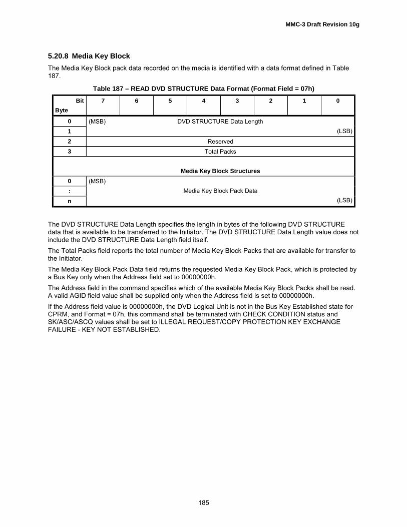
MMC-3 Draft Revision 10g
185
5.20.8 Media Key BlockThe Media Key Block pack data recorded on the media is identified with a data format defined in Table187.
Table 187 – READ DVD STRUCTURE Data Format (Format Field = 07h)
BitByte
7 6 5 4 3 2 1 0
01
(MSB) DVD STRUCTURE Data Length(LSB)
2 Reserved3 Total Packs
Media Key Block Structures0:n
(MSB)Media Key Block Pack Data
(LSB)
The DVD STRUCTURE Data Length specifies the length in bytes of the following DVD STRUCTUREdata that is available to be transferred to the Initiator. The DVD STRUCTURE Data Length value does notinclude the DVD STRUCTURE Data Length field itself.The Total Packs field reports the total number of Media Key Block Packs that are available for transfer tothe Initiator.The Media Key Block Pack Data field returns the requested Media Key Block Pack, which is protected bya Bus Key only when the Address field set to 00000000h.The Address field in the command specifies which of the available Media Key Block Packs shall be read.A valid AGID field value shall be supplied only when the Address field is set to 00000000h.If the Address field value is 00000000h, the DVD Logical Unit is not in the Bus Key Established state forCPRM, and Format = 07h, this command shall be terminated with CHECK CONDITION status andSK/ASC/ASCQ values shall be set to ILLEGAL REQUEST/COPY PROTECTION KEY EXCHANGEFAILURE - KEY NOT ESTABLISHED.

MMC-3 Draft Revision 10g
186
5.20.9 DVD-RAM Disc Definition Structure (DDS)The DVD-RAM Disc definition is identified with the data format defined in Table 188.
Table 188 – READ DVD STRUCTURE Data Format (Format field = 08h)
BitByte
7 6 5 4 3 2 1 0
01
(MSB) DVD STRUCTURE Data Length(LSB)
2 Reserved3 Reserved
DVD-RAM Disc Definition Structure (DDS)
0� DDS Information
2047
The DVD STRUCTURE Data Length specifies the length in bytes of the following DVD STRUCTUREdata that is available to be transferred to the Initiator. The DVD STRUCTURE Data Length value does notinclude the DVD STRUCTURE Data Length field itself.The DDS Information is taken from the Defect Controls of the DVD-RAM media lead-in. The length of theDDS Information is currently 2 048 bytes only.When a READ DVD STRUCTURE command with a format field value of 08h is presented for other thanDVD-RAM media, the command shall be terminated with CHECK CONDITION status and SK/ASC/ASCQvalues shall be set to ILLEGAL REQUEST/INVALID FIELD IN CDB.
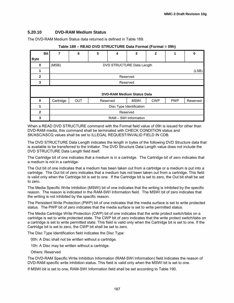
MMC-3 Draft Revision 10g
187
5.20.10 DVD-RAM Medium StatusThe DVD-RAM Medium Status data returned is defined in Table 189.
Table 189 – READ DVD STRUCTURE Data Format (Format = 09h)
BitByte
7 6 5 4 3 2 1 0
0 (MSB) DVD STRUCTURE Data Length1 (LSB)2 Reserved3 Reserved
DVD-RAM Medium Status Data
0 Cartridge OUT Reserved MSWI CWP PWP Reserved1 Disc Type Identification2 Reserved3 RAM � SWI Information
When a READ DVD STRUCTURE command with the Format field value of 09h is issued for other thanDVD-RAM media, this command shall be terminated with CHECK CONDITION status andSK/ASC/ASCQ values shall be set to ILLEGAL REQUEST/INVALID FIELD IN CDB.
The DVD STRUCTURE Data Length indicates the length in bytes of the following DVD Structure data thatis available to be transferred to the Initiator. The DVD Structure Data Length value does not include theDVD STRUCTURE Data Length field itself.The Cartridge bit of one indicates that a medium is in a cartridge. The Cartridge bit of zero indicates thata medium is not in a cartridge.The Out bit of one indicates that a medium has been taken out from a cartridge or a medium is put into acartridge. The Out bit of zero indicates that a medium has not been taken out from a cartridge. This fieldis valid only when the Cartridge bit is set to one. If the Cartridge bit is set to zero, the Out bit shall be setto zero.The Media Specific Write Inhibition (MSWI) bit of one indicates that the writing is inhibited by the specificreason. The reason is indicated in the RAM-SWI Information field. The MSWI bit of zero indicates thatthe writing is not inhibited by the specific reason.The Persistent Write Protection (PWP) bit of one indicates that the media surface is set to write protectedstatus. The PWP bit of zero indicates that the media surface is set to write permitted status.The Media Cartridge Write Protection (CWP) bit of one indicates that the write protect switch/tabs on acartridge is set to write protected state. The CWP bit of zero indicates that the write protect switch/tabs ona cartridge is set to write permitted state. This field is valid only when the Cartridge bit is set to one. If theCartridge bit is set to zero, the CWP bit shall be set to zero.The Disc Type Identification field indicates the Disc Type: 00h: A Disc shall not be written without a cartridge. 10h: A Disc may be written without a cartridge. Others: ReservedThe DVD-RAM Specific Write Inhibition Information (RAM-SWI Information) field indicates the reason ofDVD-RAM specific write inhibition status. This field is valid only when the MSWI bit is set to one.If MSWI bit is set to one, RAM-SWI Information field shall be set according to Table 190.

MMC-3 Draft Revision 10g
188
Table 190 – RAM-SWI Information field definition
Value Description
00h Reserved01h Bare Disc Write Inhibition (Disc Type Identification field of 00h and no cartridge)
02h-FEh ReservedFFh Unspecified reason
5.20.11 DVD-RAM Spare Area InformationThe DVD-RAM Spare Area Information data returned is defined in Table 191.
Table 191 – READ DVD STRUCTURE Data Format (Format = 0Ah)
BitByte
7 6 5 4 3 2 1 0
0 (MSB) DVD STRUCTURE Data Length1 (LSB)2 Reserved3 Reserved
DVD-RAM Spare Area Information
0 (MSB)1 Number of unused Primary Spare blocks23 (LSB)4 (MSB)5 Number of unused Supplementary Spare blocks67 (LSB)8 (MSB)9 Number of allocated Supplementary Spare blocks
1011 (LSB)
When a READ DVD STRUCTURE command with the Format field value of 0Ah is issued for other thanDVD media which is capable of allocation of the Supplementary Spare area, this command shall beterminated with CHECK CONDITION status and SK/ASC/ASCQ values shall be set to ILLEGALREQUEST/INVALID FIELD IN CDB.The Initiator can recognize whether the media is capable of allocation of the Supplementary Spare areaor not, indicated in the Defect Management Feature Descriptor reported by the GET CONFIGURATIONcommand.The DVD STRUCTURE Data Length indicates the length in bytes of the following DVD Structure data thatis available to be transferred to the Initiator. The DVD Structure Data Length value does not include theDVD STRUCTURE Data Length field itself.The Number of unused Primary Spare blocks field indicates the number of unused spare blocks in thePrimary Spare area.

MMC-3 Draft Revision 10g
189
The number of unused Supplementary Spare blocks field indicates the number of unused spare blocks inthe Supplementary Spare area.The number of allocated Supplementary Spare blocks field indicates the number of allocated spareblocks in the Supplementary Spare area.
5.20.12 RMD in the last Border-outThe RMD field recorded in the Border-out is defined in Table 192.
Table 192 – READ DVD STRUCTURE Data Format (Format field = 0Ch)
BitByte
7 6 5 4 3 2 1 0
01
(MSB) DVD STRUCTURE Data Length(LSB)
2 Reserved3 Reserved
RMD in last Border-out
0… RMDn
The DVD STRUCTURE Data Length specifies the length in bytes of the following DVD STRUCTUREdata that is available to be transferred to the Initiator. The DVD STRUCTURE Data Length value does notinclude the DVD STRUCTURE Data Length field itself.The RMD Bytes field returns the RMD that is written in the last recorded Border-out.The Address field in the command specifies the starting RMD Field number where the read operationshall begin. The Allocation Length field in the command specifies the maximum number of RMD bytesthat shall be returned. The largest RMD available is 30 720 bytes (15 sectors).

MMC-3 Draft Revision 10g
190
5.20.13 Recording Management Area DataThe DVD-R/-RW Recording Management Data Structure sectors recorded in the RMA, on the media, isidentified with the data format defined in Table 193. This format is available only for DVD-R/-RW media.For other media, this format is reserved.
Table 193 – READ DVD STRUCTURE Data Format (Format field = 0Dh)
BitByte
7 6 5 4 3 2 1 0
01
(MSB) DVD STRUCTURE Data Length(LSB)
2 Reserved3 Reserved
DVD-R/-RW Recording Management Data Structure
0123
(MSB)Last Recorded RMA Sector Number/
Start Sector Number of Valid Format 3 RMD Set(LSB)
4… RMD Bytesn
The DVD STRUCTURE Data Length specifies the length in bytes of the following DVD STRUCTUREdata that is available to be transferred to the Initiator. The DVD STRUCTURE Data Length value does notinclude the DVD STRUCTURE Data Length field itself.Last Recorded RMA Sector Number / Start Sector Number of Valid Format 3 RMD Set field indicates theRMA sector number where the last RMD is recorded. On DVD-RW restricted overwritten media, this fieldindicates the start sector number of valid Format 3 RMD Set.The RMD Bytes field returns RMD that is written in RMA. The Address field in the command specifies thestarting address of the RMA sector where the read operation shall begin. The Allocation Length field inthe command specifies the maximum length of the descriptor returned to the Initiator. The returned RMDdata shall end at the next ECC boundary.The maximum number of RMD bytes that can be returned is 32768.

MMC-3 Draft Revision 10g
191
5.20.14 Pre-recorded Information in Lead-inThe Pre-recorded Information in Lead-in area recorded on the media is identified with a data formatdefined in Table 194. This format is available only for DVD-R/-RW media. For other media, this format isreserved.
Table 194 – READ DVD STRUCTURE Data Format (Format field = 0Eh)
BitByte
7 6 5 4 3 2 1 0
0 (MSB) DVD STRUCTURE Data Length1 (LSB)2 Reserved3 Reserved
DVD-R Pre-recorded Information Structure
0 Field ID ( = 1)1 Disc Application code2 Disc Physical code3 (MSB)4 Last address of Data Recordable Area5 (LSB)6 Reserved (DVD-R/-RW Ver.1.0)
Part Version (R for General Ver.2.0/R forAuthoring Ver.2.0
Extension code (R for General Ver.2.0/R forAuthoring Ver.2.0)
7 Reserved8 Field ID ( = 2)9 OPC Suggested Code
10 Wavelength Code (all R media) /OPC suggested code (RW Ver.1.0)
11 - 14 Write Strategy Code15 Reserved16 Field ID ( = 3)
17 - 22 Manufacturer ID23 Reserved24 Field ID ( = 4)
25 - 30 Manufacturer ID31 Reserved32 Field ID ( = 5)
33 - 38 Manufacturer ID (R Ver.1.0) /Write Strategy code (RW Ver.1.0 /R for General Ver.2.0/R for Authoring Ver.2.0)
39 Reserved40 - 63 Reserved

MMC-3 Draft Revision 10g
192
The DVD STRUCTURE Data Length specifies the length in bytes of the following DVD STRUCTUREdata that is available to be transferred to the Initiator. The DVD STRUCTURE Data Length value does notinclude the DVD STRUCTURE Data Length field itself.The contents of Pre-recorded information are specified by the DVD Specifications for Recordable Disc,Part 1 or DVD Specifications for Re-recordable Disc Part 1.
5.20.15 Unique Disc IdentifierThe Unique Disc Identifier data recorded on the media is identified with a data format defined in Table195. This format is available only for DVD-R/-RW media. For other media, this format is invalid andreserved.
Table 195 – READ DVD STRUCTURE Data Format (Format field = 0Fh)
BitByte
7 6 5 4 3 2 1 0
0 (MSB) DVD STRUCTURE Data Length1 (LSB)2 Reserved3 Reserved
DVD-R/-RW Unique Disc Identifier0 Reserved1 Reserved2 (MSB) Random Number3 (LSB)4 (MSB)5 Year67 (LSB)8 (MSB) Month9 (LSB)
10 (MSB) Day11 (LSB)12 (MSB) Hour13 (LSB)14 (MSB) Minute15 (LSB)16 (MSB) Second17 (LSB)
The DVD STRUCTURE Data Length specifies the length in bytes of the following DVD STRUCTUREdata that is available to be transferred to the Initiator. The DVD STRUCTURE Data Length value does notinclude the DVD STRUCTURE Data Length field itself.This format returns the Unique Disc Identifier that is recorded in RMD Field 0.

MMC-3 Draft Revision 10g
193
5.20.16 Format Information of Control Data Zone in the Lead-in (Format 10h)This format is available only for DVD-R/-RW media. For other media, this format is invalid and reserved.This Format code returns Physical format information of Control Data Zone in the Lead-in area even if thedisc is recorded with multi-bordered area.
Table 196 – READ DVD STRUCTURE Data Format (With Format field = 10h)
BitByte
7 6 5 4 3 2 1 0
0 Book Type Part Version1 Disc Size Maximum Rate2 Reserved Number of Layers Track
PathLayer Type
3 Linear Density Track Density4 00h5 (MSB)6 Starting Physical Sector Number of Data Area7 (LSB)8 00h9 (MSB)
10 End Physical Sector Number of Data Area11 (LSB)12 00h13 (MSB)14 End Physical Sector Number in Layer 015 (LSB)16 BCA Reserved
17 - 2047 Media Specific
The Media Specific field shall return information as specified in the associated DVD specification.The other field definitions are same as the definitions of Format code 00h.

MMC-3 Draft Revision 10g
194
5.20.17 Disc Control BlocksThe Address field of the READ DVD STRUCTURE command shall contain a Content Descriptor toidentify the Disc Control Blocks (DCB) requested. Valid values are as shown in Table 197.
Table 197 – Content Descriptor
ContentDescriptor
Definition
00000000h Reserved00000001h -FFFFFFFDh
The DCB with a matching Content Descriptor is returned
FFFFFFFEh ReservedFFFFFFFFh Return a list of readable and writable DCB Content
Descriptors
Disc Control Block data returned is formatted as shown in Table 198.
Table 198 – READ DVD STRUCTURE Data Format (Format field = 30h)
BitByte
7 6 5 4 3 2 1 0
0 (MSB) DVD STRUCTURE Data Length1 (LSB)2 Reserved3 Reserved
Specific Disc Control Block Information0…
32767DCB Data
Each Disc Control Block is up to 16 sectors in length. The first 40 bytes of the block have a commondefinition, and the remaining bytes depend on the value of the Content Descriptor field. The Disc ControlBlock is defined in the DVD+RW 4.7 Gbytes Basic Formats Specifications. If a Disc Control Block, withfewer than 32 768 bytes is read, the Logical Unit shall pad the Disc Control Block with 00h bytes.

MMC-3 Draft Revision 10g
195
Table 199 – Generic Disc Control Block
BitByte
7 6 5 4 3 2 1 0
0 (MSB)1 Content Descriptor23 (LSB)4 (MSB)5 Unknown Content Descriptor Actions67 (LSB)
8 - 39 Vendor ID40-
32 767DCB Data
The DVD STRUCTURE Data Length specifies the length in bytes of the following DVD STRUCTUREdata that is available to be transferred to the Initiator. The DVD STRUCTURE Data Length value doesnot include the DVD STRUCTURE Data Length field itself.The Content Descriptor field identifies the contents of bytes 40 - 32 767.The Unknown Content Descriptor Actions field contains a bit mask. This mask shall describe actions theLogical Unit is allowed to perform if the Logical Unit does not know the Content Descriptor. Each bit,when set to one, shall prohibit the corresponding action. When set to zero, the corresponding action isallowed.
Table 200 – Unknown Content Descriptor Actions
Bit Actions
0 Recording within the user data area1 Reading DCBs2 Formatting of the medium3 Modification of this DCB
4 -31 Reserved
The Vendor ID field contains 24 arbitrary bytes.When Content Descriptor FFFFFFFFh (Table 201) is requested, the Logical Unit shall generate a list ofDCBs that may be read from and/or recorded on the current medium by the Initiator. If the Logical Unitrecords DCBs that are generated internally, and those DCBs cannot be sent from the Initiator, the LogicalUnit shall not report those DCBs as recordable.

MMC-3 Draft Revision 10g
196
Table 201 – Disc Control Block (FFFFFFFFh)
BitByte
7 6 5 4 3 2 1 0
0123
(MSB)Content Descriptor = FFFFFFFFh
(LSB)
4 Reserved5 Reserved6 Reserved7 Reserved
8 – 39 Vendor ID40 Reserved41 Number of Readable DCBs (= M)42 Reserved43 Number of Recordable DCBs (= N)44 (MSB)45 Readable DCB 04647 (LSB)
M * 4 + 40 (MSB)M * 4 + 41 Readable DCB M-1M * 4 + 42M * 4 + 43 (LSB)
Table 201 – Disc Control Block (FFFFFFFFh) cont.
BitByte
7 6 5 4 3 2 1 0
M * 4 + 44 (MSB)M * 4 + 45 Recordable DCB 0M * 4 + 46M * 4 + 47 (LSB)
(M + N) * 4 + 40 (MSB)Recordable DCB N � 1
(M + N) * 4 + 43 (LSB)
The Content Descriptor field shall contain FFFFFFFFh.The Unknown Content Descriptor Actions field shall be set to 0.The Vendor ID field shall be set to the value the Logical Unit uses for its own DCBs.

MMC-3 Draft Revision 10g
197
The Number of Readable DCBs field shall identify the number of entries in the Readable DCB list.The Number of Recordable DCBs field shall identify the number of entries in the Recordable DCB list.Each Readable DCB field shall contain a Content Descriptor of a DCB that may be read from themedium.Each Recordable DCB field shall contain a Content Descriptor of a DCB that may be sent from theInitiator. If a DCB is both readable and recordable, the DCB shall appear in both lists. The Logical Unitshall not record any DCB that it does not recognize.
5.20.18 Write Protection StatusThe Write protection status is returned in the format as shown in Table 202.
Table 202 – READ DVD STRUCTURE Data Format (Format field = C0h)
BitByte
7 6 5 4 3 2 1 0
0 (MSB) DVD STRUCTURE Data Length1 (LSB)2 Reserved3 Reserved
Write Protection Status0 Reserved MSWI CWP PWP SWPP1 Reserved2 Reserved3 Reserved
The DVD STRUCTURE Data Length field specifies the length in bytes of the following DVD STRUCTUREdata that is available to be transferred to the Initiator. The DVD STRUCTURE Data Length value does notinclude the DVD STRUCTURE Data Length field itself.The Software Write Protection until Power down (SWPP) bit of one indicates that the software writeprotection is active. The SWPP bit of zero indicates that the software write protection is inactive. If theLogical Unit does not support SWPP, this bit shall be set to zero.The Persistent Write Protection (PWP) bit of one indicates that the media surface is set to write protectedstatus. The PWP bit of zero indicates that the media surface is set to write permitted status. If themounted medium and Logical Unit do not support PWP, this bit shall be set to zero.The Media Cartridge Write Protection (CWP) bit of one indicates that the write protect switch/tabs on acartridge is set to write protected state. The CWP bit of zero indicates that the write protect switch/tabs ona cartridge is set to write permitted state. If the cartridge does not have CWP function or medium ismounted without cartridge, this bit shall be set to zero. Otherwise, CWP bit shall indicate its actual status.The Media Specific Write Inhibition (MSWI) bit of one indicates that any writing is inhibited by the mediaspecific reason. The MSWI bit of zero indicates that writing is not inhibited by the media specific reason.
5.20.18.1 DVD Structure ListThe DVD Structure List is returned in the format as shown in Table 203.

MMC-3 Draft Revision 10g
198
Table 203 – READ DVD STRUCTURE Data Format (Format field = FFh)
BitByte
7 6 5 4 3 2 1 0
0 (MSB) DVD STRUCTURE Data Length1 (LSB)2 Reserved3 Reserved
DVD Structure List0 - n
Structure List
The DVD STRUCTURE Data Length specifies the length in bytes of the following DVD STRUCTUREdata that is available to be transferred to the Initiator. The DVD STRUCTURE Data Length value does notinclude the DVD STRUCTURE Data Length field itself.The Structure List is returned as a sequence of Structure List Entries as shown in Table 204.Note: This DVD Structure is generated by the Logical Unit rather than read from the medium.
Table 204 – Structure List Entry
BitByte
7 6 5 4 3 2 1 0
0 Format Code1 SDS RDS Reserved2 (MSB) Structure Length3 (LSB)
The Format Code field shall identify a DVD Structure that is readable via the READ DVD STRUCTUREcommand.The SDS bit, when set to zero, shall indicate that the DVD structure is not writable via the SEND DVDSTRUCTURE command. When set to one, shall indicate that the DVD structure is writable via the SENDDVD STRUCTURE command.The RDS bit, when set to zero, shall indicate that the DVD structure is not readable via the READ DVDSTRUCTURE command. When set to one, shall indicate that the DVD structure is readable via the READDVD STRUCTURE command.The Structure Length field shall specify the length of the DVD Structure that is identified by the FormatCode.

MMC-3 Draft Revision 10g
199
Table 205 describes errors that may occur during the operation of the command or which may cause aCHECK CONDITION status to be reported.
Table 205 – Recommended errors for READ DVD STRUCTURE Command
Error Reference
Deferred Errors A.2General Errors Table A.2Media Access Errors Table A.3

MMC-3 Draft Revision 10g
200
5.21 READ FORMAT CAPACITIES CommandThe READ FORMAT CAPACITIES command (Table 206) allows the Initiator to request a list of thepossible format capacities for an installed random-Writable media. This command also has the capabilityto report the capacity for a media when it is installed. If the command is required, by an implementedFeature it shall function independently of the state of that Feature�s Current bit.The Allocation Length field specifies the maximum number of bytes that an Initiator has allocated forreturned data. An Allocation Length of zero indicates that no data shall be transferred. This condition shallnot be considered as an error. The Logical Unit shall terminate the data transfer when Allocation Lengthbytes have been transferred or when all available data have been transferred to the Initiator, whatever isless.
Table 206 – READ FORMAT CAPACITIES Command
BitByte
7 6 5 4 3 2 1 0
0 Operation Code (23h)1 Reserved Reserved2 Reserved3 Reserved4 Reserved5 Reserved6 Reserved7 (MSB) Allocation Length8 (LSB)9 Control
Table 207 – READ FORMAT CAPACITIES Data Format
BitByte
7 6 5 4 3 2 1 0
0 - 3 Capacity List Header4 – 11 Current/Maximum Capacity Descriptor
Formattable Capacity Descriptor(s)
0.. Formattable Capacity Descriptor 07
….0.. Formattable Capacity Descriptor n7

MMC-3 Draft Revision 10g
201
Table 208 – Capacity List Header
BitByte
7 6 5 4 3 2 1 0
0 Reserved1 Reserved2 Reserved3 Capacity List Length
The Capacity List Length specifies the length in bytes of the Capacity Descriptors that follow. EachCapacity Descriptor is eight bytes in length, making the Capacity List Length equal to eight times thenumber of descriptors. Values of n * 8 are valid, where 0 < n < 32.
Table 209 – Current/Maximum Capacity Descriptor
BitByte
7 6 5 4 3 2 1 0
4567
(MSB)Number of Blocks
(LSB)
8 Reserved Descriptor Type9
1011
(MSB)Block Length
(LSB)
The Number of Blocks indicates the number of addressable blocks for the capacity defined by eachDescriptor Type.The Descriptor Type field (Table 210) indicates the type of information the descriptor contains.
Table 210 – Descriptor Types
Descriptor Type Description
00b Reserved01b Unformatted Media. The reported value is for the maximum formatted capacity for this
media. For DDCD/CD-RW medium, the value reported is the maximum possiblewhen using Format Type 10h.
10b Formatted Media. The reported value is the current media�s capacity. In the case ofsequential writable media, the number of blocks field indicates the number of blocksbetween the first Lead-in and the Lead-out or Border-out. When the media done nothave a complete session it shall be reported as �No Media Present� with DescriptorType = 11b.
11b No Media Present. The reported value is for the maximum capacity of a media thatthe Logical Unit is capable of reading.
The Block Length specifies the length in bytes of each logical block.

MMC-3 Draft Revision 10g
202
Table 211 – Formattable Capacity Descriptor(s)
BitByte
7 6 5 4 3 2 1 0
0 (MSB)1 Number of Blocks23 (LSB)4 Format Type Reserved5 (MSB)6 Type Dependent Parameter7 (LSB)
The Format Type field, Table 212, indicates the type of information required for formatting.
Table 212 – Format Types
FormatType
Description Type DependentParameter
00h The descriptor shall contain the number of addressable blocks and the blocksize used for formatting the whole media. If multiple formatting for the wholemedia is possible, each capacity/block size combination shall be reported asa separate descriptor.
Block length inbytes
01h The descriptor shall contain the number of addressable blocks and the blocksize used for formatting the whole media. If multiple formatting for the wholemedia is possible, each capacity/block size combination shall be reported asa separate descriptor. This Format Type is used to expand a Spare area.
Block length inbytes
02h � 03h Reserved04h The descriptor shall contain the number of addressable blocks in the zone
and zone number used by zoned formatting for a zone of the media, wherethe size of zone is not constant for each zone. The information for each zoneshall be reported as a separate descriptor.
Zone number of thedescription
05h The descriptor shall contain the number of addressable blocks per zone andzone number of the highest numbered zone. This descriptor is used for zonedformatting of the media, where the size of zone is constant for each zone.
Zone number of thelast zone
06h � 0Fh Reserved10h The descriptor shall contain the maximum number of addressable blocks and
maximum packet size that can be used to fully format CD/DVD-RW media.The packet size and number of addressable blocks may be adjusteddownward by the Initiator before sending this descriptor back via theFORMAT UNIT command.
Fixed Packet Sizein sectors/ECCblock size insectors
11h The descriptor shall contain the maximum number of addressable blocks andthe packet size that can be used to expand (grow) the last complete sessionof CD/DVD-RW media. The number of addressable blocks may be adjusteddownward by the Initiator before sending this descriptor back via theFORMAT UNIT command.
Fixed Packet Sizein sectors/ECCblock size insectors
12h The descriptor shall contain the maximum number of addressable blocks andthe maximum packet size that can be used to add a new session to aCD/DVD-RW media. The packet size and number of addressable blocks maybe adjusted downward by the Initiator before sending this descriptor back viathe FORMAT UNIT command.
Fixed Packet Sizein sectors/ECCblock size insectors

MMC-3 Draft Revision 10g
203
Table 213 – Format Types, continued
FormatType
Description Type DependentParameter
13h The descriptor shall contain the maximum number of addressable blocks andthe ECC block size which can be used to expand (grow) the last completeSession of DVD-RW media as an intermediate state. The number ofaddressable blocks may be adjusted downward by the initiator beforesending this descriptor back via the FORMAT UNIT command.
ECC block size insectors
14h The descriptor shall contain the maximum number of addressable blocks andthe ECC block size that can be used to add a new intermediate state Sessionto a DVD-RW media. The number of addressable blocks may be adjusteddownward by the initiator before sending this descriptor back via theFORMAT UNIT command.
ECC block size insectors
15h The descriptor shall contain the maximum number of addressable blocks andECC block size that can be used to fully format DVD-RW media as anintermediate state. The number of addressable blocks may be adjusteddownward by the initiator before sending this descriptor back via theFORMAT UNIT command.
ECC block size insectors
16h � 1Fh Reserved20h
(Obsolete)The descriptor shall contain the maximum number of addressable blocks andthe sparing parameters to be used.
M and N (sparingparameters
21h-23h Reserved24h MRW Format, Mandatory for the MRW Feature. The descriptor shall contain
the maximum number of DMA addressable blocks.The TypeDependentParameter is notused and shall becleared to zero.
26h DVD+RW Full Format, Mandatory for the DVD+RW Profile The TypeDependentParameter is notused and shall becleared to zero.
25h - 3Fh Reserved
The Number of Blocks field indicates the number of addressable blocks for the capacity defined by eachFormat Type.The Type Dependent Parameter contents are as specified for each Format Type in Table 212. In the caseof Format Type 20h (Obsolete), M specifies SL where SL = 2M , 4 ≤ M ≤ 15 or SL = 0 if M = 0 and Nidentifies SI where SI = 2N , 4 ≤ N ≤ 24.The Type Dependent Parameter shall be set to M * 10000h + N, effectively placing M in byte offset 5 andN in byte offset 7, and making byte 8 reserved. The device shall supply its default values for M and N.The Logical Unit shall only return Formattable Capacity Descriptors that apply to the installed media. Ifthere is no medium installed, the Logical Unit shall return only the Current/Maximum Capacity Descriptor,with the maximum capacity of a medium that the Logical Unit is capable of reading.A Formattable Capacity Descriptor of Format Type 00h shall be reported if any other FormattableCapacity Descriptor is reported.The descriptors shall be returned in ascending order of Format Type. For Format Types other than 04hand 05h, if multiple format descriptors exist, they shall be returned in Logical Unit preferred order. ForFormat Types 04h and 05h, the format descriptors shall be returned in ascending order of Zone number.Formattable Capacity Descriptors for formats that can be read, but not formatted shall not be reported.

MMC-3 Draft Revision 10g
204
Table 214 indicates the values returned if the Logical Unit implements the command.
Table 214 – Returned Current/Maximum Descriptor for Combination of Logical Unit and Media
Logical UnitType
No Media ROM Media Sequential WritableMedia
Random WritableMedia
ROM DescriptorType = 11b
DescriptorType = 10b
Descriptor Type =10b or 11b
Descriptor Type =10b
SequentialWritable
Descriptor Type =10b
Descriptor Type =10b
RandomWritable
Descriptor Type =10b or 11b
Descriptor Type =01b or 10b plusFormattableCapacityDescriptor(s)
This command is not mandatory for all Logical Unit types shown in Table 214; the table indicates thevalues returned if the command is implemented.Table 215 describes errors that may occur during the operation of the command or which may cause aCHECK CONDITION status to be reported.
Table 215 – Recommended errors for READ FORMAT CAPACITIES Command
Error Reference
Deferred Errors A.2General Errors Table A.2Media Access Errors Table A.3

MMC-3 Draft Revision 10g
205
5.22 READ SUB-CHANNEL CommandThe READ SUB-CHANNEL command (Table 216) requests that the Logical Unit return the requestedSub-channel data plus the state of audio play operations.NOTE: Sub-channel data, returned by this command, may be from the last appropriate sector,encountered by a current or previous media accessing operation. When there is no current audio playoperation, the Logical Unit may access the media to read the Sub-channel data. The Logical Unit isresponsible for ensuring that the data returned is current and consistent.
Table 216 – READ SUB-CHANNEL Command
BitByte
7 6 5 4 3 2 1 0
0 OPERATION CODE (42h)1 RESERVED Reserved TIME Resvd2 Resvd SUBQ Reserved3 Sub-channel Parameter List4 Reserved5 Reserved6 Track Number (Hex)7 (MSB) Allocation Length8 (LSB)9 Control
The TIME bit allows selection of address reporting format. If TIME is cleared to zero, the reportedaddress format is Logical Block Address, represented as a 32-bit integer with ms-byte first. If TIME is setto one, the reported address format is Time, as shown in Table 2.When the sub Q bit is set to one, the Logical Unit shall return the Q Sub-channel data. When the sub Qbit is cleared to zero, the Logical Unit shall return no Sub-channel data. This shall not be considered anerror.The Sub-channel parameter list (Table 217) field specifies the returned sub channel data.
Table 217 – Sub-channel parameter list codes
Format Code Returned Data
00h Reserved01h CD current position02h Media Catalog number (UPC/bar code)03h Track International standard recording code (ISRC)04h - EFh ReservedF0h - FFh Vendor specific
The Track Number field specifies the track number from that ISRC data is read. This field shall have avalue between 01h and 63h (99bcd), and is valid only when the Sub-channel parameter list field is 03h. Inthis case, the Logical Unit returns ISRC data for this track. This field may contain 00h when the Formatcode is not 03h.

MMC-3 Draft Revision 10g
206
5.22.1 Sub-channel Data HeaderThe Sub-channel data header format (Table 218) is four bytes. If the Sub Q bit is zero, in the command,the Logical Unit shall return only the Sub-channel data header. In this case, the Sub-channel data lengthis 0.
Table 218 – Sub-Q Channel Data Header Format
BitByte
7 6 5 4 3 2 1 0
0 Reserved1 Audio Status2 (MSB) Sub-channel Data Length3 (LSB)
The audio status field indicates the status of audio play operations. The audio status values are defined inTable 219. Logical Units that do not support audio play operations shall always report 00h.For Logical Units that support audio operations: The initial value for audio status is 15h. Audio statusvalues 13h and 14h return information on previous audio operations. When audio play stops due to anerror and the IMMED bit in the CD Audio Control Mode Page (see 6.3.7) is set to one, the Logical Unitshall report 14h in this audio status byte and shall report no deferred error.
Table 219 – Audio status codes
Status Description
00h Audio status byte not supported or not valid01h - 10h Reserved
11h Audio play operation in progress12h Audio play operation paused13h Audio play operation successfully completed14h Audio play operation stopped due to error15h No current audio status to return
16h - FFh Reserved
The Sub-channel data length field specifies the length in bytes of the following Sub-channel data block. ASub-channel data length of zero indicates that no Sub-channel data block is included in the returned data.Sub-channel data length does not include the sub channel header.

MMC-3 Draft Revision 10g
207
5.22.2 Sub-channel Data Format (01h), CD current positionTable 220 defines the response data format for the CD current position data format.
Table 220 – CD current position data format
BitByte
7 6 5 4 3 2 1 0
0 Sub-channel Data Format Code (01h)1 ADR CONTROL2 TRACK NUMBER3 INDEX NUMBER4
7
(MSB)Absolute CD Address
(LSB)8
11
(MSB)Track Relative CD Address
(LSB)
The ADR field gives the type of information encoded in the Q Sub-channel of this block, as shown inTable 221.
Table 221 – ADR Q Sub-channel field
ADR Code Description
0h Q Sub-channel mode information not supplied1h Q Sub-channel encodes current position data
(i.e., track, index, absolute address, relative address)2h Q Sub-channel encodes media catalog number3h Q Sub-channel encodes ISRC
4h - Fh Reserved
The control field is described in Table 222.The bits of the control field (except for the copy bit) can change during an actual pause (X=00) of at least2 seconds and during the Lead-in area only.

MMC-3 Draft Revision 10g
208
Table 222 – Q Sub-channel control field
Field Definitions
00x0b 2 audio channels without pre-emphasis00x1b 2 audio channels with pre-emphasis of 50/15 µs10x0b audio channels without pre-emphasis (reserved in CD-R/RW)10x1b audio channels with pre-emphasis of 50/15 µs (reserved in CD-R/RW)01x0b Data track, recorded uninterrupted01x1b Data track, recorded incremental11xxb Reservedxx0xb digital copy prohibitedxx1xb digital copy permitted
Table 223 – Q Sub-channel control field for DDCD
Field Definitions
0100b Data track, recorded uninterrupted or recorded incremental
The Track Number field contains the current track number.The Index Number field contains the current index number.The Absolute CD Address field gives the current location relative to the logical beginning of the media. Ifthe TIME bit, (Table 216) is zero, this field is an LBA. If the TIME bit is one, the address is TIME. SeeTable 2 for a definition of the TIME field.The Track Relative CD Address field gives the current location relative to the logical beginning of thecurrent track. If the MSF bit is zero, this field is a track relative LBA. (If the current block is in the pre-gaparea of a track, this is a negative value, expressed as a two�s-complement number.) If the MSF bit in theCDB is set to one, this field is the relative TIME address from the Q Sub-channel.The control data and current position data is obtained from the Q Sub-channel information of the currentblock. Identification data may be reported that was obtained from a previous block. If identification data isreported, the data shall be valid for the sector addressed by the current position data.a) If an audio play operation is proceeding in the background, position data for the last sector played
shall be reported.b) In other cases, for instance after a READ command, the Logical Unit may either report position data
for the last sector processed for that operation or may report position data from the sector at thecurrent read head position.
Note: When the type of information encoded in the Q Sub-channel of the current sector is the mediacatalog number or ISRC, the track, index, and address fields should be extrapolated from the previoussector.

MMC-3 Draft Revision 10g
209
5.22.3 Sub-channel Data Format (02h), Media Catalog NumberWith a Sub-channel format code of 02h the data returned is the Media Catalog Number. The MediaCatalog field contains the identifying number of this media is expressed in ASCII. A value in this field of allASCII zeros indicates that the media catalog number is not supplied. Table 224 defines the media catalognumber data format.
Table 224 – Media Catalog Number data format
BitByte
7 6 5 4 3 2 1 0
0 Sub-channel Data Format Code (02h)1 Reserved2 Reserved3 Reserved4... Media Catalog Number... (MCN)19
If media catalog number data is found, the MCVAL bit is set to one. If MCN data is not detected, theMCVAL bit is set to zero to indicate the media catalog number field is invalid.Media Catalog Number (see Table 225) data returned in bytes 4 through 19 by this command with Sub-channel data format field code 02h may be from any block that has MCN Q Sub-channel data. See sub-clause 4.2.3.4.2.
Table 225 – MCN Format of Data Returned
Byte Char Bit 7 Bit 6 Bit 5 Bit 4 Bit 3 Bit 2 Bit 1 Bit 0
0 MCVAL Reserved1 N1 N1 (Most significant)2 N2 N23 N3 N3... ... ...12 N12 N1213 N13 N13 (Least significant)14 Zero15 AFRAME
The Media Catalog Number, N1 through N13, when sent to the Initiator, is formatted as ASCII characters.The MCVAL bit when set to one, indicates the Media Catalog Number field is valid.AFRAME may return the frame number where the MCN was found. This shall be a value from 00h to4Ah. All other values are reserved.

MMC-3 Draft Revision 10g
210
5.22.4 Sub-channel Data Format (03h), International Standard Recording CodeThe track ISRC field contains the identifying number of this media according to the ISRC standards (DIN-31-621) expressed in ASCII. Table 226 defines the Track International Standard Recording Code dataformat. A unique ISRC may exist for each track.
Table 226 – Track International Standard Recording Code data format
BitByte
7 6 5 4 3 2 1 0
0 Sub-channel Data Format Code (03h)1 ADR CONTROL2 Track Number3 Reserved4 (MSB)… Track International Standard Recording Code (ISRC)19 (LSB)
If ISRC data is detected, the TCVAL bit (see Table 227) is set to one. If ISRC data is not detected, theTCVAL bit is set to zero to indicate the ISRC field is invalid.The ADR and control fields shall be returned from the ADR and Control fields on the media.The Track Number shall indicate the track for that the ISRC was requested.Track ISRC data (see Table 227) may be from any block in the specified track that has ISRC data. WhenADR field is 3 (0011b), it is used to assign a unique number to an audio track. This is done by means ofthe ISRC that is 12 characters long (represented by I1 to I12, see Table 227.) The ISRC shall onlychange immediately after the TNO has been changed.ISRC data returned is encoded as ASCII characters. The format of the data is defined in Table 227.
Table 227 – ISRC Format of Data Returned
Byte Char Bit 7 Bit 6 Bit 5 Bit 4 Bit 3 Bit 2 Bit 1 Bit 0
0 TCVAL Reserved1 I1 I1 (Country Code)2 I2 I23 I3 I3 (Owner Code)4 I4 I45 I5 I56 I6 I6 (Year of Recording)7 I7 I78 I8 I8 (Serial Number)9 I9 I9
10 I10 I1011 I11 I1112 I12 I1213 Zero14 AFRAME15 Reserved

MMC-3 Draft Revision 10g
211
All bytes are specified in ASCII. The following translation (Table 228) is specified for multimedia LogicalUnits:
Table 228 – ISRC Translation
The following codes shall be valid for the above fields (Table 227):a) Country Code: �A� - �Z� (41h - 5Ah)b) Owner Code: �0� - �9� and �A� - �Z� (30h -39h, 41h - 5Ah)c) Year of Recording: �0� - �9� (30h - 39h)d) Serial Number: �0� - �9� (30h - 39h)e) The Zero field shall return 00h.f) AFRAME may return the frame number in that the MCN was found. This shall be a value from 00h to
4Ah. All other values are reserved.Table 229 describes errors that may occur during the operation of the command or which may cause aCHECK CONDITION status to be reported.
Table 229 – Recommended errors for READ SUB-CHANNEL Command
Error or ASCQ Reference
Deferred Errors A.2General Errors Table A.2Media Access Errors Table A.3AUDIO PLAY OPERATION IN PROGRESS Table A.1AUDIO PLAY OPERATION PAUSED Table A.1AUDIO PLAY OPERATION SUCCESSFULLY COMPLETED Table A.1AUDIO PLAY OPERATION STOPPED DUE TO ERROR Table A.1NO CURRENT AUDIO STATUS TO RETURN Table A.1
ASCII Hex MEDIA
�0� - �9� 30h - 39h 00 - 09h
�@� - �o� 40h - 6Fh 10h - 3Fh

MMC-3 Draft Revision 10g
212
5.23 READ TOC/PMA/ATIP CommandThe READ TOC/PMA/ATIP command (Table 230) requests that the Logical Unit transfer data from theTable of Contents, the Program Memory Area (PMA), and the Absolute Time in Pre-Grove (ATIP) fromCD media. For media that does not support a TOC, fabricated information is returned that is similar tothat of CD media for some formats. This fabrication is required for some legacy Initiator environments.
Table 230 – READ TOC/PMA/ATIP Command
BitByte
7 6 5 4 3 2 1 0
0 OPERATION CODE (43h)1 Reserved Reserved TIME Reserved
2 Reserved Format3 Reserved4 Reserved5 Reserved6 Track/Session Number7 (MSB) Allocation Length8 (LSB)9 Control
The TIME bit requests the address form of all reported addresses. If TIME is cleared to zero, then alladdress reporting shall be in Logical Block Addresses. If TIME is set to one, then all address reportingshall be in the TIME format as shown in Table 2.The Format field specifies the form of returned data. Valid Format field values and their meanings areshown in Table 231.

MMC-3 Draft Revision 10g
213
Table 231 – Format Field
Formatfield
Return Data Optional/Mandatory
Description Track/Session
fieldUsage
0000b TOC M The Track/Session Number field specifies starting track numberfor which the data is returned. For multi-session discs, thiscommand returns the TOC data for all sessions and for Tracknumber AAh only the Lead-out area of the last completesession. See Table 233.
TrackNumber
0001b Session Info M This format returns the first complete session number, lastcomplete session number and last complete session startingaddress. In this format, the Track/Session Number field isreserved and should be set to 00h. NOTE: This format providesthe Initiator access to the last finalized session starting addressquickly. See Table 235.
Reserved
0010b Full TOC M(for CD)
This format returns all Q sub-code data in the Lead-In (TOC)areas starting from a session number as specified in theTrack/Session Number field. In this mode, the Logical Unit shallsupport Q Sub-channel POINT field value of A0h, A1h, A2h,Track numbers, B0h, B1h, B2h, B3h, B4h, C0h, and C1h. SeeTable 236. There is no defined LBA addressing and TIME bitshall be set to one.
SessionNumber
0011b PMA O This format returns all Q sub-code data in the PMA area. In thisformat, the Track/Session Number field is reserved and shall beset to 00h. See Table 241. There is no defined LBA addressingand TIME bit shall be set to one.
Reserved
0100b ATIP O This format returns ATIP data. In this format, the Track/SessionNumber field is reserved and shall be set to 00h. See Table242. There is no defined LBA addressing and TIME bit shall beset to one.
Reserved
0101b CD-TEXT O This format returns CD-TEXT information that is recorded in theLead-in area as R-W Sub-channel Data
Reserved
All OtherFormatCodes
Reserved. Reserved
The Track/Session Number field specifies the starting track number for that the data shall be returned.The data is returned in contiguous ascending track number order. A value of AAh requests that thestarting address of the Lead-out area be returned. If this value is zero, the Table of Contents data shallbegin with the first track or session on the medium.If the Track/Session Number field is not valid for the currently installed medium, the command shall beterminated with CHECK CONDITION status and SK/ASC/ASCQ shall be set to ILLEGALREQUEST/INVALID FIELD IN CDB.When a Read TOC/PMA/ATIP command is presented for a DDCD/CD-R/RW media, where the first TOChas not been recorded (no complete session) and the Format codes 0000b, 0001b, or 0010b arespecified, this command shall be rejected with an INVALID FIELD IN CDB. Devices that are not capableof reading an incomplete session on DDC/CD-R/RW media shall report CANNOT READ MEDIUM �INCOMPATIBLE FORMAT.

MMC-3 Draft Revision 10g
214
5.23.1 READ TOC Response parameter list, general definitionThe response parameter list (see Table 232) indicates the general description of the response data to theRead TOC/PMA/ATIP command. Each descriptor field is format specific and is defined in the appropriateformat sub-clause.
Table 232 – READ TOC/PMA/ATIP parameter list, general definition
BitByte
7 6 5 4 3 2 1 0
0 (MSB) Data Length1 (LSB)2 First Track/Session/Reserved Field(Hex)3 Last Track/Session/Reserved Field(Hex)
Parameter List Descriptor(s)0: Descriptor data , format specific:n
The Data Length indicates the length, in bytes, of the parameter list descriptor data.The Track/Session/Reserved Field is format specific and indicates the location, if any, of the informationin the parameter list descriptors.Descriptor data fields are format specific. The definitions of the bytes are described in each format sub-clause.

MMC-3 Draft Revision 10g
215
5.23.2 TOC/PMA/ATIP Response Data Format 0000bThe response data consist of four header bytes and zero or more track descriptors. The response data isdependent upon the format specified in the format field of the CDB. The response data returned forFormat 0000b is specified in Table 233.
Table 233 – READ TOC/PMA/ATIP response data (Format = 0000b)
BitByte
7 6 5 4 3 2 1 0
0 (MSB) TOC Data Length1 (LSB)2 First Track Number(Hex)3 Last Track Number(Hex)
TOC Track Descriptor(s)0 Reserved1 ADR CONTROL2 Track Number(Hex)3 Reserved4 (MSB)… Track Start Address7 (LSB)
The TOC data length indicates the length in bytes of the following TOC data. The TOC data length valuedoes not include the TOC data length field itself. This value is not modified when the allocation length isinsufficient to return all of the TOC data available.
5.23.2.1 General Case for CDThe First Track Number field indicates the first track number in the first complete session Table ofContents.The Last Track Number field indicates the last track number in the last complete session Table ofContents before the Lead-out.The ADR field (Table 221) gives the type of information encoded in the Q Sub-channel of the block wherethis TOC entry was found.The Control Field (Table 222) indicates the attributes of the track.The Track Start Address contains the address of the first block with user information for that track numberas read from the Table of Contents. A TIME bit of zero indicates that the Track Start Address field shallcontain a logical block address. A TIME bit of one indicates the Logical Block Address field shall contain aTIME address (see sub-clause 4.1.6).The Track Number field indicates the track number for that the data in the TOC track descriptor is valid. Atrack number of AAh indicates that the track descriptor is for the start of the Lead-out area.

MMC-3 Draft Revision 10g
216
5.23.2.2 CD-MRW DeviationsIf the disc is MRW formatted or in progress with MRW formatting, form 0 of the TOC shall be reported asfollows:One track, track number = 1, ADR = 0001b, and CONTROL = 0110b. The track start addresses are shown inTable 234.
Table 234 – Track Start Address for MRW Discs
LBA Space TIME bit Track 1 StartAddress
Lead-out Start Address
GAA 1 00:02:00 Regardless of the state of the MRW formatting process,only the final state is reported. The link separating thelast GAA packet and the first DMA packet is reported:00:18:43.
GAA 0 0 1024
DMA 1 00:18:47 Regardless of the state of the MRW formatting process,only final state is reported. The absolute address of thefinal state link block separating the last DMA packet andthe first STA packet is reported.
DMA 0 0 C+1, where C is the LBA of the last user block of the lastpacket in the DMA..
5.23.2.3 DDCD DeviationsFor DDCD, the control field is always set to 0100b (see table 324).
5.23.2.4 DVD-ROM, DVD-RAM, DVD+RW, and Single Session DVD-R/-RWDVD has no tracks and no sub-channel. "TOC" data shall be fabricated as follows:
First track =1, Last track = 1
Track 1 descriptor:ADR = 1hCONTROL = 4hTrack number = 01hStart Address = 0h when TIME = 0, Start Address = 00h, 00h, 02h, 00h. when TIME = 1.
Track 0aah descriptor:ADR = 1hCONTROL = 4hTrack number = 0aahStart Address = actual start of lead-out LBA, when TIME = 0,Start Address = translation with a maximum of 00h, 0ffh, 3bh, 4ah. when TIME = 1.

MMC-3 Draft Revision 10g
217
5.23.2.5 DVD-R/-RW with Multiple SessionsDVD-R/-RW may have multiple sessions. Since the number of sessions may be rather large, only twosessions are represented as tracks: the last session is seen as a the last user track. All earlier sessionsare concatenated into a single logical track to be referred to as track 1. TOC form 0001b shall befabricated as follows:
First track =1, Last track = 1
Track 1 descriptor:ADR = 1hCONTROL = 4hTrack number = 01hIf TIME = 0, Start Address = 0h, else Start Address = 00h, 00h, 02h, 00h.
Track 2 descriptor:ADR = 1hCONTROL = 4hTrack number = 02hIf TIME = 0, Start Address = actual start LBA of last bordered area,else, Start Address = translation with a maximum of 00h, 0ffh, 3bh, 4ah.
Track 0aah descriptor:ADR = 1hCONTROL = 4hTrack number = 01hIf TIME = 0, Start Address = actual start of lead-out LBA,else, Start Address = translation with a maximum of 00h, 0ffh, 3bh, 4ah.

MMC-3 Draft Revision 10g
218
5.23.3 TOC/PMA/ATIP Response Data Format 0001bThe response data returned for Format 0001b is specified in Table 235.
Table 235 – READ TOC/PMA/ATIP response data (Format = 0001b)
BitByte
7 6 5 4 3 2 1 0
0 (MSB) TOC Data Length1 (LSB)2 First Complete Session Number (Hex)3 Last Complete Session Number (Hex)
TOC Track Descriptor0 Reserved1 ADR CONTROL2 First Track Number In Last Complete Session (Hex)3 Reserved4 (MSB)… Start Address of First Track in Last Session7 (LSB)
The TOC Data Length specifies the length in bytes of the available session data. The TOC Data Lengthvalue does not include the TOC Data Length field itself. This value is not modified when the allocationlength is insufficient to return all of the session data available.The First Complete Session Number is set to one.The Last Complete Session Number indicates the number of the last complete session on the disc. TheLast Complete Session Number shall be set to one for a single session disc or if the Logical Unit does notsupport multi-session discs.The ADR field (Table 221) gives the type of information encoded in the Q Sub-channel of the block wherethis TOC entry was found.The Control Field (Table 221) indicates the attributes of the track. First Track Number In Last CompleteSession returns the first track number in the last complete session.The Track Start Address contains the address of the first block with user information for the first track ofthe last session, as read from the Table of Contents.
5.23.3.1 CD-MRW DeviationsIf the disc is MRW formatted or in progress with MRW formatting, form 1 of the TOC shall report onesession with one track. The track starting address shall be reported as shown in Table 234.

MMC-3 Draft Revision 10g
219
5.23.3.2 DVD-ROM, DVD-RAM, DVD+RW, and DVD-R/-RWDVD has no tracks and no sub-channel. "TOC" data shall be fabricated as follows:First Complete Session Number =1, Last Complete Session number = 1
TOC track descriptor:ADR = 1hCONTROL = 4hFirst Track Number In Last Complete Session = 01hIf TIME = 0, Start Address of First Track in Last Session = 0h,else, Start Address of First Track in Last Session = 00h, 00h, 02h, 00h.

MMC-3 Draft Revision 10g
220
5.23.4 TOC/PMA/ATIP Response Data Format 0010bNone of the fields in the response data of Format 0010b are affected by the TIME bit in the CDB. Theresponse data returned for Format 0010b is specified in Table 236.
Table 236 – READ TOC/PMA/ATIP response data (Format = 0010b)
BitByte
7 6 5 4 3 2 1 0
0 (MSB) TOC Data Length1 (LSB)2 First Complete Session Number (Hex)3 Last Complete Session Number (Hex)
TOC Track Descriptor(s)0 Session Number (Hex)1 ADR CONTROL2 TNO3 POINT4 Min5 Sec6 Frame7 Zero
HOUR PHOUR8 PMIN9 PSEC
10 PFRAME
Multiple TOC Track Descriptors may be returned, but only one of each entry is reported.For Format field of 0010b, the Logical Unit shall return TOC data for Q Sub-channel modes 1 and 5(except mode 5, point 1 through 40) in the Lead-in area.The TOC Data Length specifies the length in bytes of the available TOC data. The TOC Data Lengthvalue does not include the TOC Data Length field itself. This value is not modified when the allocationlength is insufficient to return all TOC data available.The First Complete Session Number shall be set to one.The Last Complete Session Number indicates the number of the last complete session on the disc. TheLast Complete Session Number is set to one for a single session disc or if the Logical Unit does notsupport multi-session discs.The ADR field (Table 221) gives the type of information encoded in the Q Sub-channel of the block wherethis TOC entry was found.The Control Field (Table 222) indicates the attributes of the track.The ZERO field shall contain a value of zero for CD media other than DDCD media. For DDCD media thisfield shall contain the value HOUR in bits 7-4 and PHOUR in bits 3-0.Entries in bytes 2 through 7 of the descriptors (TNO, POINT, MIN, SEC, FRAME, ZERO) shall beconverted to hex by the Logical Unit if the media contains a value between 0 and 99bcd. For DDCD

MMC-3 Draft Revision 10g
221
bytes 7 through 10 (PHOUR, PMIN, PSEC, and PFRAME) shall be converted to hex by the Logical Unit ifthe media contains a value between 0 and 99bcd. Otherwise, the value is returned with no modification.The returned TOC data of a multi-session disc is arranged in ascending order of the session number withduplicates removed. The TOC data within a session is arranged in the order of Q Sub-channel POINTfield value of A0h � AFh, Track Numbers, B0h, BFh. Only recorded Points shall be returned.The TOC Track Descriptor format in the Lead-in area of the TOC is described in Table 237.
Table 237 – TOC Track Descriptor Format, Q Sub-channel
CTRL ADR TNO POINT MIN SEC FRAME ZERO PMIN PSEC PFRAME
4 or 6 1 00h 01h-63h ATIME (Absolute time) 00h Start position of track4 or 6 1 00h A0h ATIME (Absolute time) 00h First Track
NumberDiscType
00h
4 or 6 1 00h A1h ATIME (Absolute time) 00h Last TrackNumber
00h 00h
4 or 6 1 00h A2h ATIME (Absolute time) 00h Start position of Lead-out4 or 6 5 00h B0h Start time of next possible program in
the Recordable Area of the disc# of
pointers inMode 5
Maximum start time of outer-mostLead-out area in the Recordable
Area of the disc4 or 6 5 00h B1h 00h 00h 00h 00h # of skip
intervalPointers(N<=40)
# of skipTrack
Pointers(N<=21)
00h
4 or 6 5 00h B2h-B4h Skip # Skip # Skip # Skip # Skip # Skip # Skip #4 or 6 5 00h 01h-40h Ending time for the interval that
should be skippedReserved Start time for interval that should
be skipped on playback4 or 6 5 00h C0h optimum
recordingpower
Reserved Reserved Reserved Start time of the first Lead-in Areaof the disc
4 or 6 5 00h C1h Copy of information from A1 point in ATIP.
If the disc is MRW formatted or in progress with MRW formatting, form 2 of the TOC shall be constructed tocontain the values expected when formatting has completed.
The DDCD TOC Track Descriptor format in the Lead-in area of the TOC is described in Table 238.All of the TOC Track Descriptors, in Table 237, are further define in sub-clause found. The POINT Field(Table 239) defines various types of information within the TOC Lead-in area.

MMC-3 Draft Revision 10g
222
Table 238 – DDCD TOC Track Descriptor Format, Q Sub-channel
CTRL ADR TNO POINT MIN SEC FRAME HOUR PHOUR PMIN PSEC PFRAME
4 1 00h 01h-63h ATIME (Absolute time) Start position of track4 1 00h A0h ATIME (Absolute time) 0000b First
TrackNumber
DiscType20h
00h
4 1 00h A1h ATIME (Absolute time) 0000b LastTrackNumber
00h 00h
4 1 00h A2h ATIME (Absolute time) Start position of Lead-out4 1 00h F0h ATIME (Absolute time) 0000b Book
typeBookver.
Material type
Momentof inertia
4 5 00h B0h Start time of next possibleprogram in the Recordable /ReWritable Area of the disc
Maximum start time of outer-mostLead-out area in the Recordable /ReWritable Area of the disc
4 5 00h C0h Copy of SpecialInformation1 in ATIP(ROM: reserved and
set to zero)
# ofMode5 ptrs
Start time of the first Lead-in Area ofthe disc
4 5 00h C1h Copy of AdditionalInformation1 in ATIP.
0000b Set to zero
4 5 00h CFh Stop position of Inner part Lead-out Area
Start position of outer part Lead-in Area
Table 239 – POINT Field
ADR POINT Field Description
1 01-63h Track number references1 A0h First Track number in the program area1 A1h Last Track number in the program area1 A2h Start location of the Lead-out area5 01-40h Skip Interval Pointers5 B0h Used to Identify a Multi-session Disc (Photo CD) Contains start time of next
possible program area5 B1h Number of skip interval pointers & Skip track assignments5 01-40h Skip Interval Pointers5 B2-B4h Skip Track Assignment Pointers5 C0h Start time of first Lead-in area of disc (This only exists in the first Lead-in
area)5 C1h Copy of information from additional area 1 in ATIP.

MMC-3 Draft Revision 10g
223
The Disc Type field (see Table 240) indicates the type of disc inserted.
Table 240 – Disc Type Byte Format
Value Description
00h CD-DA or CD Data with first track in Mode 110h CD-I disc20h CD data XA disc with first track in Mode 2, DDCD disc
5.23.4.1 CD-MRW DeviationsIf the disc is MRW formatted or in progress with MRW formatting form 2 of the TOC, PMA, shall be constructedto contain the values expected when formatting has completed.
5.23.4.2 DVD-ROM, DVD-RAM, DVD+RW, and DVD-R/-RWNo fabrication for DVD media is defined for form 0010b.

MMC-3 Draft Revision 10g
224
5.23.5 TOC/PMA/ATIP Response Data Format 0011bNone of the fields in the response data of Format 0011b are affected by the TIME bit in the CDB. Theresponse data returned for Format 0011b is specified in Table 241.
Table 241 – READ TOC/PMA/ATIP response data (Format = 0011b)
BitByte
7 6 5 4 3 2 1 0
0 (MSB) PMA Data Length1 (LSB)2 Reserved3 Reserved
PMA Descriptor(s)
0 Reserved1 ADR CONTROL2 TNO3 POINT4 Min5 Sec6 Frame7 Zero
HOUR PHOUR8 PMIN9 PSEC
10 PFRAME
Multiple PMA Descriptors may be returned.The returned PMA descriptors are arranged in the order found in the PMA, with duplicates removed.The PMA Data Length indicates the length in bytes of the available PMA data. The PMA Data Lengthvalue does not include the PMA Data Length field itself. This value is not modified when the allocationlength is insufficient to return all PMA data available. This value is set to 2 plus eleven times the numberof descriptors read.The ZERO field shall contain a value of zero for CD media other than DDCD media. For DDCD media thisfield shall contain the value HOUR in bits 7-4 and PHOUR in bits 3-0.Entries in bytes 2 through 10 of the descriptors, (TNO, POINT, MIN, SEC, FRAME, Zero), shall beconverted to binary by the Logical Unit if the media contains a value between 0 and 99bcd. (See4.2.3.8.2)
5.23.5.1 CD-MRW DeviationsIf the disc is MRW formatted or in progress with MRW formatting form 3 of the TOC, PMA, shall be constructedto contain the values expected when formatting has completed.
5.23.5.2 DVD-ROM, DVD-RAM, DVD+RW, and DVD-R/-RW
No fabrication for DVD media is defined for form 0011b.

MMC-3 Draft Revision 10g
225
5.23.6 TOC/PMA/ATIP Response Data Format 0100bNone of the fields in the response data of Format 0100b are affected by the TIME bit in the CDB. Theresponse data returned for Format 0100b is specified in Table 242.
Table 242 – READ TOC/PMA/ATIP response data (Format = 0100b)
BitByte
7 6 5 4 3 2 1 0
0 (MSB) ATIP Data Length1 (LSB)2 Reserved3 Reserved
ATIP Descriptor
0 Indicative Target Writing Power (DDCD) Reference Speed
1 0 URU Reserved2 1 Disc Type Disc Sub-Type A1 Valid A2 Valid A3 Valid3 Reserved4 ATIP Start Time of Lead-in (Min)5 ATIP Start Time of Lead-in (Sec)6 ATIP Start Time of Lead-in (Frame)7 Reserved8 ATIP Last Possible Start Time of Lead-out (Min)9 ATIP Last Possible Start Time of Lead-out (Sec)
10 ATIP Last Possible Start Time of Lead-out (Frame)11 Reserved
12 – 14 A1 Values15 Reserved
16-18 A2 Values19 Reserved
20-22 A3 Values23 RESERVED
24-26 S4 Values27 Reserved
ATIP Data Length specifies the number of bytes to be transferred in response to the command. The ATIPData Length value does not include the data length field itself. This value is not modified when theAllocation Length is insufficient to return all of the ATIP data available.ATIP Descriptor field definition is dependent upon the setting of the DDCD bit. When the DDCD bit iscleared to zero, the fields are defined for CD-R/RW media. When the DDCD bit is set to one, the fieldsare defined for DDCD-R/RW media.

MMC-3 Draft Revision 10g
226
5.23.6.1 ATIP Descriptor for CD-R/RW MediaIndicative Device Writing Power - encoded information indicating the media�s recommended initial laserpower setting. The field is contained within the low order 3 bits of the field. The high order bit shall be setto one. The meaning of the field varies between CD-R and CD-RW media (see the Orange Books).Reference Speed - is encoded information indicating the recommended write speed for the media:
00h = reserved and 01h = 2X recording. This is valid only for CD-RW media.The Unrestricted Use Disc (URU) flag, when set to one, indicates that the mounted CD-R/RW disc isdefined for unrestricted use. When the URU flag is set to zero, the mounted CD-R/RW disc is defined forrestricted use. To record data to the mounted disc the appropriate Host Application code shall be setthrough the Write Parameters Mode Page.A Host Application Code of zero may be used to indicate a restricted use disc - general purpose.Disc Type - zero indicates CD-R media; one indicates CD-RW media.Disc Sub-Type - reports the following value according to the Orange Book Part 2 or Part 3 (B1,B2,B3).A1 - when set to one, indicates that the A1 Values field is valid. Otherwise, the A1 Values field is invalid.A2 - when set to one, indicates that the A2 Values field is valid. Otherwise, the A2 Values field is invalid.A3 - when set to one, indicates that the A3 Values field is valid. Otherwise, the A3 Values field is invalid.ATIP Start time of Lead-in - the start time of the lead-in. The value is read from ATIP and returned in hexformat. Legal values for the M field are 50h through 63h.ATIP Last Possible Start Time of Lead-out - the last possible start time of lead-out. The value is read fromATIP and returned in hex format. Valid values for the M field are 0 through 4Fh.
Table 243 – Disc Type and Disc Sub Type field definition
Media Disc Type Disc Sub-Type Field Definition
CD-R 0 See Orange Book Media Type (Physical Characteristic)
000 Standard Speed CD-RWCD-RW 1
001 High Speed CD-RW
For description of A1, A2, and A3 (Additional-Info1,2, and 3) fields, please refer to the applicable OrangeBook. For the recording speed, refer to mode page 2Ah or Set Stream command.
5.23.6.2 ATIP Descriptor for DDCD-R/RW MediaIndicative Device Writing Power - encoded information indicating the media�s recommended initial laserpower setting. Unlike the CD version, the field is contained within the entire field.Reference Speed - is encoded information indicating the recommended write speed for the media:
000b-001b = reserved, 010b = 4x recording, 011b = 8x recording, and 100b-111b is reserved.The Unrestricted Use Disc (URU) bit is unchanged when used with DDCD media.A Host Application CodeDisc Type - zero indicates DDCD-R media; one indicates DDCD-RW media.Disc Sub-Type - has no meaning for DDCD and is reservedA1, A2, and A3 are unchanged when used with DDCD media.ATIP Start time of Lead-in - the start time of the lead-in. The value is binary and not in the HMSF format.ATIP Last Possible Start Time of Lead-out - the last possible start time of lead-out. The value is binaryand not in the HMSF format.

MMC-3 Draft Revision 10g
227
The special information 4(S4) fields are available for both DDCD-R and DDCD-RW.
5.23.6.3 TOC/PMA/ATIP Format 0100b for DVD MediaTOC/PMA/ATIP format 0100b has no definition for data fabrication for DVD media. If the Initiatorrequests a TOC/PMA/ATIP of this form. the Logical Unit shall terminate the command with CHECKCONDITION status and set sense bytes SK/ASC/ASCQ to ILLEGAL REQUEST/INVALID FIELD IN CDB.

MMC-3 Draft Revision 10g
228
5.23.7 TOC/PMA/ATIP Response Data Format 0101bNone of the fields in the response data of Format 0101b (Table 244) are affected by the TIME bit in theCDB.When a Read TOC/PMA/ATIP command with the Format code 0101b is presented for a DDCD-R/RWmedia, this command shall be rejected with an INVALID FIELD IN CDB.
Table 244 – READ TOC/PMA/ATIP response data (With Format Field = 0101b )
BitByte
7 6 5 4 3 2 1 0
0 (MSB) CD-TEXT Data Length1 (LSB)2 First Track/Session/Reserved Field(Hex)3 Last Track/Session/Reserved Field(Hex)
CD-TEXT Descriptor(s)
0: Descriptor data , format specific:N
CD-TEXT Data Length specifies the number of bytes to be transferred in response to the command. TheATIP Data Length value does not include the data length field itself. This value is not modified when theallocation length is insufficient to return all of the CD-TEXT data available. This length is variable dependson the number of recording Pack Data.CD-TEXT Information Descriptor(s) provides Pack Data available in the lead-in area of the disc. EachPack Data consists of 18 bytes of CD-TEXT information. If a Pack Data is recorded repeatedly on thedisc, the device should return it only once.The detail of Pack Data and CD-TEXT information is described in .TOC/PMA/ATIP format 0101b has no definition for data fabrication for DVD media. If the Initiatorrequests a TOC/PMA/ATIP of this form. the Logical Unit shall terminate the command with CHECKCONDITION status and set sense bytes SK/ASC/ASCQ to ILLEGAL REQUEST/INVALID FIELD IN CDB.
Table 245 describes errors that may occur during the operation of the command or which may cause aCHECK CONDITION status to be reported.
Table 245 – Recommended errors for READ TOC/PMA/ATIP Command
Error or ASCQ Reference
Deferred Errors A.2General Errors Table A.2Media Access Errors Table A.3AUDIO PLAY OPERATION IN PROGRESS Table A.1
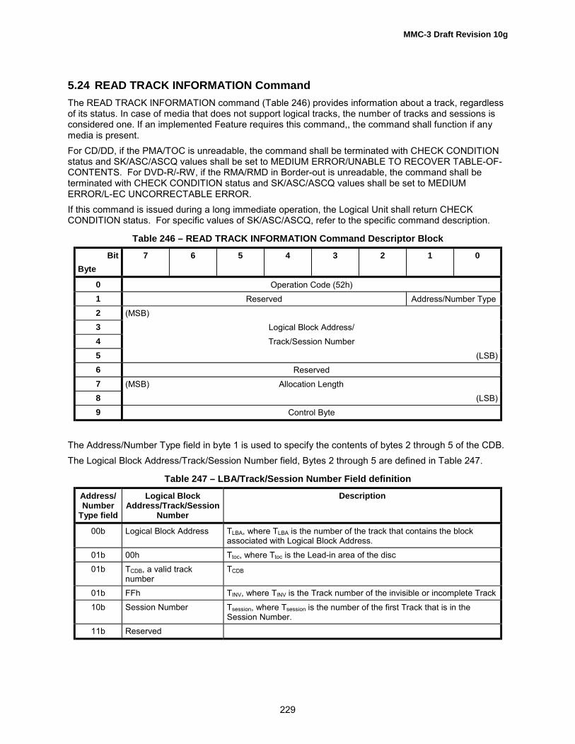
MMC-3 Draft Revision 10g
229
5.24 READ TRACK INFORMATION CommandThe READ TRACK INFORMATION command (Table 246) provides information about a track, regardlessof its status. In case of media that does not support logical tracks, the number of tracks and sessions isconsidered one. If an implemented Feature requires this command,, the command shall function if anymedia is present.For CD/DD, if the PMA/TOC is unreadable, the command shall be terminated with CHECK CONDITIONstatus and SK/ASC/ASCQ values shall be set to MEDIUM ERROR/UNABLE TO RECOVER TABLE-OF-CONTENTS. For DVD-R/-RW, if the RMA/RMD in Border-out is unreadable, the command shall beterminated with CHECK CONDITION status and SK/ASC/ASCQ values shall be set to MEDIUMERROR/L-EC UNCORRECTABLE ERROR.If this command is issued during a long immediate operation, the Logical Unit shall return CHECKCONDITION status. For specific values of SK/ASC/ASCQ, refer to the specific command description.
Table 246 – READ TRACK INFORMATION Command Descriptor Block
BitByte
7 6 5 4 3 2 1 0
0 Operation Code (52h)1 Reserved Address/Number Type2 (MSB)3 Logical Block Address/4 Track/Session Number5 (LSB)6 Reserved7 (MSB) Allocation Length8 (LSB)9 Control Byte
The Address/Number Type field in byte 1 is used to specify the contents of bytes 2 through 5 of the CDB.The Logical Block Address/Track/Session Number field, Bytes 2 through 5 are defined in Table 247.
Table 247 – LBA/Track/Session Number Field definition
Address/Number
Type field
Logical BlockAddress/Track/Session
Number
Description
00b Logical Block Address TLBA, where TLBA is the number of the track that contains the blockassociated with Logical Block Address.
01b 00h Ttoc, where Ttoc is the Lead-in area of the disc01b TCDB, a valid track
numberTCDB
01b FFh TINV, where TINV is the Track number of the invisible or incomplete Track10b Session Number Tsession, where Tsession is the number of the first Track that is in the
Session Number.11b Reserved

MMC-3 Draft Revision 10g
230
The number of Track Information Block bytes returned is limited by the Allocation Length parameter of theCDB. An Allocation Length of zero is not an error. Fields not used with the installed media shall return 0.The format and content of the Track Information Block is shown in Table 248.
Table 248 – Track Information Block
BitByte
7 6 5 4 3 2 1 0
0 (MSB) Data Length1 (LSB)2 Track Number (Least Significant Byte)3 Session Number (Least Significant Byte)4 Reserved5 Reserved Damage Copy Track Mode6 RT Blank Packet/Inc FP Data Mode7 Reserved LRA_V NWA_V8 (MSB)9 Track Start
10 Address11 (LSB)12 (MSB)13 Next Writable14 Address15 (LSB)16 (MSB)17 Free18 Blocks19 (LSB)20 (MSB)21 Fixed Packet Size/22 Blocking Factor23 (LSB)24 (MSB)25 Track Size2627 (LSB)28 (MSB)29 Last Recorded Address3031 (LSB)32 Track Number (Most Significant Byte)33 Session Number (Most Significant Byte)34 Reserved35 Reserved

MMC-3 Draft Revision 10g
231
Data length field specifies the length, in bytes, of the requested data to be transferred in response to thecommand. The data length value does not include the data length field itself. If the Allocation lengthspecified is less than the data length, the response shall be truncated at the allocation length specified.This truncation shall not cause a CHECK CONDITION status to be presented. The Data Length is notmodified when the allocation length is insufficient to return all of the response data available.Track Number is the track number for all of the information in this structure or a value of 1 for media notcontaining logical tracks. If the Track number is set to zero, and the P through W bit is set (see Table350), the contents of Track Information Block shall be returned for the lead-in area. In this case, the TrackStart Address field is the start address of the lead-in area.Session Number is the number of the session containing this track, or a value of 1 for media notcontaining sessions that contain this track.The Copy bit indicates that this track is a second or higher generation copy. For media that does notsupport CGMS, this bit shall beset to zero.The Damage bit, when set to one, and the NWA_V is set to zero, the track shall be considered "notclosed due to an incomplete write�. The Logical Unit may attempt an automatic repair when the CLOSETRACK/SESSION command is issued. Further incremental writing in this track is not possible. TheDamage bit, when set to one, and the NWA_V is set to one, indicates a Track that may be recordedfurther in an incremental manner. The Logical Unit shall attempt an automatic repair when the nextcommand that requires writing to the Track is issued. If the repair is successful, the Damage bit shall beset to zero. Prior to the start of the repair, the NWA field shall contain the address of the Next WritableSector assuming a successful repair.Track Mode is the control nibble as defined for mode 1 Q Sub-channel for this track. For non-CD media,this field shall be set to 4. See Table 347 and Table 222. For DDCD, this field shall be set to 4.For CD/DD, if the RT bit is zero, then the track is not reserved, otherwise the track is reserved. The RTbit indicates that a PMA entry indicating the tracks start and end addresses exists. For DVD, the RT bit ofzero indicates that the Track is Complete, Invisible, or Incomplete status. A RT bit of one indicates thatthe Track is Empty Reserved or Partially Recorded Reserved status.If the Logical Unit is not capable of reading the PMA or RMA, this field shall be set to zero.The Blank bit, when set to one, indicates that the track contains no written data and Last RecordedAddress field is invalid. For CD/DD, Tracks with the Track Descriptor Block recorded shall not beconsidered blank. For other media, this bit shall be set to zero.For CD/DD, the Packet/Inc bit is valid only when the RT bit is set to one or the track indicated is theincomplete track. The Packet/Inc bit, when set to one, indicates that this track is to be written only withpackets (CD) or incremental recording (DVD).The FP (Fixed Packet) bit is valid only when the Packet/Inc bit is set to one. When the Packet/Inc bit is setto one and the FP bit is also set to one, then the track is to be written only with fixed packets on CD/DDmedia, or the track is to be written with restricted overwrite method on DVD-RW media. When thePacket/Inc bit is set to one and the FP bit is set to zero, then the track is to be written only with variablepackets on CD/DD media, or the track is to be written with incremental recording on DVD-R/-RW media.Except for C/DD/DVD-R/-RW, this field should be set to zero.When writing, certain parameters may be set via the Write Parameters Page. The state of the trackdetermines what parameters shall be set and that parameters in the mode page shall match. RequiredWrite Parameters are defined in Table 249.

MMC-3 Draft Revision 10g
232
Table 249 – Write Parameter Restrictions due to Track State
RT Blank Packet CD Write Parameter Restrictions DVD Write Parameter Restrictions
0 0 0 Can�t write to stamped disc, or duringtrack at once on invisible track, or writingsession at once mode
Can�t write to stamped disc, or writingdisc-at-once, can not write to completedisc.
0 0 1 Write type is set to packet; all parameterscommon to READ TRACK INFOMATIONand the Write Parameters Page shallmatch.
Write type is set to incremental; allparameters common to READ TRACKINFOMATION and the Write ParametersPage shall match
0 1 0 Write type may be set to packet or TAO.All other parameters shall bechangeable. If this track is the first trackof a Session, then Session at Once isallowed.
Write type is set to disc-at-once: InvisibleTrack of disc-at-once, empty. Can�t startdisc-at-once recording in this state. ATrack shall be reserved prior to start ofdisc-at-once recording. All parameterscommon to READ TRACK INFOMATIONand the Write Parameters Page shallmatch
0 1 1 Invalid State Write type is set to incremental; Invisibletrack for incremental recording, the Trackis writable. All parameters common toREAD TRACK INFOMATION and theWrite Parameters Page shall match
1 0 0 Can�t write to recorded track or duringtrack at once on reserved Track.
Can�t write to disc during disc at once onreserved Track.
1 0 1 Write type is set to packet; all parameterscommon to READ TRACK INFO and theWrite Parameters Page shall match.
Write type is set to incremental; Partiallyrecorded reserved Track, the Track iswritable. All parameters common toREAD TRACK INFOMATION and theWrite Parameters Page shall match
1 1 0 Write type is set to TAO. Track mode setto same as READ TRACK INFO. Copybit may be set only if copyright bit in trackmode is clear. All other commonparameters shall match.
Write type is set to disc-at-once; Emptyreserved Track for disc-at-once. Allparameters common to READ TRACKINFOMATION and the Write ParametersPage shall match
1 1 1 Write type is set to Packet. Track modeset to same as READ TRACK INFO.Copy bit may be set only if copyright bitin track mode is clear. FP and packetsize are changeable. All other commonparameters shall match.
Write type is set to incremental; Emptyreserved Track, the Track is writable. Allparameters common to READ TRACKINFOMATION and the Write ParametersPage shall match
For CD, when the RT, Blank and Packet bits are set to one, FP bit of the READ TRACK INFORMATIONresponse data is set to zero.Data Mode field defines the track content. Data Mode is defined in Table 251.

MMC-3 Draft Revision 10g
233
Table 250 – Track Status Indications
DVD CDRT Blank Packet/
IncFP Write Method Track Status Write Method Track Status
0 0 0 - - DAO Complete Uninterrupted/TAO/SAO
Complete/During TAO/SAO
0 0 1 0 Incremental Incomplete orComplete (1)
Variable Incomplete
0 0 1 1 - RestrictedOverwrite
Completeor Incomplete(2)
Fixed Incomplete
0 1 0 - DAO Invisible TAO/Variable/Fixed(*3)
Invisible
0 1 1 0 Incremental Invisible - (invalid)0 1 1 1 - Restricted
OverwriteInvisible - (invalid)
1 0 0 - DAO during DAO TAO Complete/During TAO
1 0 1 0 Incremental PartiallyRecordedReserved
Variable Complete/PartiallyRecordedReserve
1 0 1 1 - (invalid) Fixed Complete/PartiallyRecordedReserve
1 1 0 - DAO EmptyReservedBefore startingwriting
TAO EmptyReserved
1 1 1 0 Incremental EmptyReserved
Variable/Fixed EmptyReserved
1 1 1 1 - (invalid) - (invalid)
(1) If Free Blocks field is 0, the track is in the Complete state. Otherwise, the track is Incomplete state.(2) In the case of a track that is in the intermediate state session, the track is considered as in theIncomplete state.(3) In case last Session is empty, SAO is also valid.
Table 251 – Data Mode
Value Definition
1 Mode 1 (ISO/IEC 10149)2 Mode 2 (ISO/IEC 10149 or CD-ROM XA)
DDCDFh Data Block Type unknown (no track descriptor block)
0, 3 - Eh Reserved

MMC-3 Draft Revision 10g
234
If NWA_V is zero, then the next writable address field is not valid. Otherwise the next writable addressfield is valid. NWA_V shall be set to zero if the Track is not writable for any reason. If the disc is MRWformatted or in progress with MRW formatting, then NWA_V shall be set to zero.If LRA_V is zero, then the Last Recorded Address field is not valid. Otherwise, the Last RecordedAddress field is valid. The LRA_V bit shall be set to zero if the Track has damage for any reason and isrepaired automatically.Track Start Address contains the address of the first block with user information for that track.The Next Writable Address, if valid, is the LBA of the next writable user block in the Track specified by theLBA/Track Number field in the CDB. For CD media, Next Writable Address shall be associated with theRT, Blank, Packet and FP bits as defined in Table 252. If the write type is Raw, the Next WritableAddress may be a negative number as required to point to the start of the first Lead-in. When streamingin any write type, the Next Writable Address shall be the next user data block the Logical Unit expects toreceive if no under-run occurs.
Table 252 – Next Writable Address Definition
RT Blank Packet FP NWA_V Definition
0 0 0 - 04 LBA that shall be specified by next write command *20 0 1 0 11 LBA that shall be specified by next write command *20 0 1 1 11 LBA that shall be specified by next write command
*2, *30 1 0 0 1 LBA of the first data block after pre-gap *50 1 1 0 - -0 1 1 1 - -1 0 0 - 04 LBA that shall be specified by next write command *21 0 1 0 11 LBA that shall be specified by next write command *21 0 1 1 11 LBA that shall be specified by next write command
*2, *31 1 0 - 1 LBA of the first data block after pre-gap1 1 1 0 1 LBA of the first data block after pre-gap1 1 1 1 - -
Notes:1 � When "Free Blocks" is 0 (data full), NWA_V is 0.2 - NWA shall be taken account of data blocks in buffer that has not yet been written to media. If the Logical Unit canwrite the data of next write command without interrupting of current data streaming(no underrun condition), NWAshall be contiguous to last address data in buffer. If WCE in Mode Cache Page is zero, NWA shall be taken accountof Link Blocks (2 Run-out blocks, 1 Link block and 4 Run-out blocks) in case of Addressing Method-1.3 - NWA shall follow the Addressing Method-2 if Method-2 bit in Mode CD Capabilities and Mechanical Status Pageis set to one.4 � During TAO (SAO), NWA_V is 1.5 - In the case of SAO NWA shall be the first block after Lead-in for the first track of session.
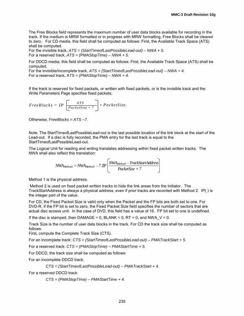
MMC-3 Draft Revision 10g
235
PacketS ize + 7A TSF reeB locks = IP • P acketS ize .
NWAMethod2 = NWAMethod1 – 7 ⋅IP NWAMethod1 - TrackStartAddressPacketSize + 7
The Free Blocks field represents the maximum number of user data blocks available for recording in thetrack. If the medium is MRW formatted or in progress with MRW formatting, Free Blocks shall be clearedto zero. For CD media, this field shall be computed as follows: First, the Available Track Space (ATS)shall be computed.For the invisible track, ATS = (StartTimeofLastPossibleLead-out) – NWA + 5.For a reserved track, ATS = (PMAStopTime) – NWA + 5.For DDCD media, this field shall be computed as follows: First, the Available Track Space (ATS) shall becomputed.For the invisible/incomplete track, ATS = (StartTimeofLastPossibleLead-out) – NWA + 4.For a reserved track, ATS = (PMAStopTime) – NWA + 4.
If the track is reserved for fixed packets, or written with fixed packets, or is the invisible track and theWrite Parameters Page specifies fixed packets,
Otherwise, FreeBlocks = ATS –7.
Note: The StartTimeofLastPossibleLead-out is the last possible location of the link block at the start of theLead-out. If a disc is fully recorded, the PMA entry for the last track is equal to theStartTimeofLastPossibleLead-out.The Logical Unit for reading and writing translates addressing within fixed packet written tracks. TheNWA shall also reflect this translation:
Method 1 is the physical address. Method 2 is used on fixed packet written tracks to hide the link areas from the Initiator. TheTrackStartAddress is always a physical address, even if prior tracks are recorded with Method 2. IP( ) isthe integer part of the value.For CD, the Fixed Packet Size is valid only when the Packet and the FP bits are both set to one. ForDVD-R, if the FP bit is set to zero, the Fixed Packet Size field specifies the number of sectors that areactual disc access unit. In the case of DVD, this field has a value of 16. FP bit set to one is undefined.If the disc is stamped, then DAMAGE = 0, BLANK = 0, RT = 0, and NWA_V = 0.Track Size is the number of user data blocks in the track. For CD the track size shall be computed asfollows:First, compute the Complete Track Size (CTS).For an incomplete track: CTS = (StartTimeofLastPossibleLead-out) – PMATrackStart + 5.For a reserved track: CTS = (PMAStopTime) – PMAStartTime + 5.For DDCD, the track size shall be computed as follows:For an incomplete DDCD track:
CTS = (StartTimeofLastPossibleLead-out) – PMATrackStart + 4.For a reserved DDCD track:
CTS = (PMAStopTime) – PMAStartTime + 4.

MMC-3 Draft Revision 10g
236
TrackSize = IP CTSPacketSize + 7
• PacketSize.If the track is reserved for, or written with, fixed packets:
Otherwise, TrackSize = CTS – 7.
READ TRACK INFORMATION shall provide certain valid fields for a disc with the Unrecordable status:Track Number, Session Number, Track Mode, Data Mode, Track Start Address.For CD media, the Track Size number may not be exact for the tracks that do not have a PMA entry. Thetrack size, of tracks that do not have PMA entries, is calculated as follows:TrackSize of track n = (start of track n+1) - (start of track n), n+1 is the Lead Out if n is the last trackrecorded in the TOC.The Track Size from this calculation may include blocks from the following track and these blocks may notbe readable.If the disc is MRW formatted or in progress with MRW formatting, Track Size shall be reported accordingto the LBA Space selected in the MRW Mode Page. The Track Size of a MRW disc is simply the sum ofall the DA sizes given in user sectors.Table 253 describes errors that may occur during the operation of the command or which may cause aCHECK CONDITION status to be reported.
Table 253 – Recommended Errors for the Read Track Information Command
Error Reference
Deferred Errors A.2General Errors Table A.2Media Access Errors Table A.3

MMC-3 Draft Revision 10g
237
5.25 REPAIR TRACK CommandA track that has been defined for incremental writing may be damaged due to an incomplete ECC block atthe end of written data. This may be caused by a reset issued or a power-fail condition during a packetwrite. The REPAIR TRACK (Table 254) command shall fill multiple ECC block lengths with data frombeginning of damaged sector of the ECC block and ended with link field. The recovery indicated here onlyallows the track to become writable again.
Table 254 – REPAIR TRACK Command Descriptor Block
BitByte
7 6 5 4 3 2 1 0
0 Operation Code (58h)1 Reserved Immed2 Reserved3 Reserved4 (MSB) Track Number5 (LSB)6 Reserved7 Reserved8 Reserved9 Control
The Immed bit allows execution of the REPAIR TRACK command function as an immediate operation. IfImmed is set to 0, then the requested repair operation is executed to completion prior to returning status.If Immed is set to 1, then status is returned once the Command Packet has been validated.The Track Number field specifies the track that requires repair.Behavior of this command is the same as automatic repair. This command causes a repair action withoutan explicit write of data.Table 255 describes errors that may occur during the operation of the command or which may cause aCHECK CONDITION status to be reported.
Table 255 – Recommended errors for REPAIR TRACK Command
Error Reference
Deferred Errors A.2General Errors Table A.2Media Access Errors Table A.3Write Errors Table A.4

MMC-3 Draft Revision 10g
238
5.26 REPORT KEY CommandThe REPORT KEY command (Table 256) requests the start of the authentication process and providesdata necessary for authentication and for generating a Bus Key for the DVD Logical Unit. This command,in conjunction with the SEND KEY command, is intended to perform authentication for Logical Units thatconform to DVD Content Protection schemes, and generates a Bus Key as the result of thatauthentication.The REPORT KEY command also requests the DVD Logical Unit to transfer TITLE KEY data, obfuscatedby a Bus Key, to the Initiator.
Table 256 – REPORT KEY Command Descriptor Block
BitByte
7 6 5 4 3 2 1 0
0 Operation Code (A4h)1 Reserved Reserved2 (MSB)3 Logical Block Address45 (LSB)6 Reserved7 Key Class8 (MSB) Allocation Length9 (LSB)
10 AGID KEY Format11 Control
The KEY Format field (Table 258) indicates the types of information that is to be sent to the Initiator.The REPORT KEY command with KEY Format field of 000000b or 010001b, initiates the authenticationprocess. The Logical Unit, when ready to begin the authentication process, shall grant the request byreturning an Authentication Grant ID (AGID). If there is no available Authentication Grant ID, thecommand shall be terminated with CHECK CONDITION status and SK/ASC/ASCQ shall be set toILLEGAL REQUEST/SYSTEM RESOURCE FAILURE.The Key Class field shall identify the type of authentication conversation according to Table 257.
Table 257 – KEY Class Definition
Key Class Authentication Type
00h DVD CSS/CPPM or CPRM01h ReWritable Security Service � A
02h - FFh Reserved
Note: DVD CSS/CPPM and CPRM authentication use the same Key Class field value since they have thesame Challenge KEY, KEY1, and KEY2 sizes, and since they are licensed through the same entity.The Allocation Length field specifies the maximum length in bytes of the REPORT KEY response datathat shall be transferred from the Logical Unit to the Host. An Allocation Length of zero indicates that nodata shall be transferred. This condition shall not be considered as an error.The AGID field is used to control simultaneous key exchange sequences. The AGID specified insubsequent Key Exchange commands shall match a currently active AGID. An AGID becomes active by
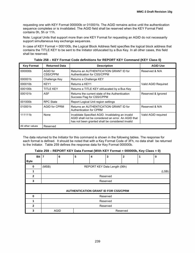
MMC-3 Draft Revision 10g
239
requesting one with KEY Format 000000b or 010001b. The AGID remains active until the authenticationsequence completes or is invalidated. The AGID field shall be reserved when the KEY Format Fieldcontains 0h, 5h or 11h.Note: Logical Units that support more than one KEY Format for requesting an AGID do not necessarilysupport simultaneous key exchange sequences.In case of KEY Format = 000100b, the Logical Block Address field specifies the logical block address thatcontains the TITLE KEY to be sent to the Initiator obfuscated by a Bus Key. In all other cases, this fieldshall be reserved.
Table 258 – KEY Format Code definitions for REPORT KEY Command (KEY Class 0)
Key Format Returned Data Description AGID Use
000000b AGID forCSS/CPPM
Returns an AUTHENTICATION GRANT ID forAuthentication for CSS/CPPM
Reserved & N/A
000001b Challenge Key Returns a Challenge KEY000010b KEY1 Returns a KEY1 Valid AGID Required000100b TITLE KEY Returns a TITLE KEY obfuscated by a Bus Key000101b ASF Returns the current state of the Authentication
Success Flag for CSS/CPPMReserved & Ignored
001000b RPC State Report Logical Unit region settings010001b AGID for CPRM Returns an AUTHENTICATION GRANT ID for
Authentication for CPRMReserved & N/A
111111b None Invalidate Specified AGID. Invalidating an invalidAGID shall not be considered an error. An AGID thathas not been granted shall be considered invalid
Valid AGID required
All other values Reserved
The data returned to the Initiator for this command is shown in the following tables. The response foreach format is defined. It should be noted that with a Key Format Code of 3Fh, no data shall be returnedto the Initiator. Table 259 defines the response data for Key Format 000000b.
Table 259 – REPORT KEY Data Format (With KEY Format = 000000b, Key Class = 0)
BitByte
7 6 5 4 3 2 1 0
0 (MSB) REPORT KEY Data Length (06h)1 (LSB)2 Reserved3 Reserved
AUTHENTICATION GRANT ID FOR CSS/CPRM
0 Reserved1 Reserved2 Reserved3 AGID Reserved

MMC-3 Draft Revision 10g
240
This KEY Format requests the Logical Unit to return an Authentication Grant ID for CSS/CPPM. If theauthentication process is started by the REPORT KEY command with a KEY Format of 000000b, theauthentication shall be processed to exchange Key data only for CSS/CPPM protected contents.Note: If the command with this KEY Format is required by an implemented Feature, the command shouldfunction, even when the current bit for that Feature is zero.Table 260 defines the response data for Key Format 000001b
Table 260 – REPORT KEY Data Format (With KEY Format = 000001b, Key Class = 0)
BitByte
7 6 5 4 3 2 1 0
0 (MSB) REPORT KEY Data Length (0Eh)1 (LSB)2 Reserved3 Reserved
Challenge Key
0 (MSB): Challenge Key Value9 (LSB)
10 Reserved11 Reserved
Challenge Key Value field returns a value to be used to interrogate an external device to determineconformance with the DVD Content Protection scheme. The external device then generates thecorresponding KEY2.Table 261 defines the response data for Key Format 000010b
Table 261 – REPORT KEY Data Format (With KEY Format = 000010b, Key Class = 0)
BitByte
7 6 5 4 3 2 1 0
0 (MSB) REPORT KEY Data Length (0Ah)1 (LSB)2 Reserved3 Reserved
KEY10 (MSB): KEY1 Value4 (LSB)5 Reserved6 Reserved7 Reserved

MMC-3 Draft Revision 10g
241
KEY1 Value field returns a value used to determine the Logical Unit�s conformity with DVD ContentProtection scheme by an external device. The KEY1 value is also used as a parameter to generate a BusKey in the Logical Unit.When the Logical Unit is unable to produce a KEY1 value, this command with KEY Format = 000010bshall be terminated with CHECK CONDITION status and SK/ASC/ASCQ shall be set to ILLEGALREQUEST/COPY PROTECTION KEY EXCHANGE FAILURE - KEY NOT PRESENT.Table 262 defines the response data for Key Format 000100b
Table 262 – REPORT KEY Data Format (With KEY Format = 000100b, Key Class = 0)
BitByte
7 6 5 4 3 2 1 0
0 (MSB) REPORT KEY Data Length (0Ah)1 (LSB)2 Reserved3 Reserved
COPYRIGHT MANAGEMENT/TITLE KEY Information0 CPM CP_SEC CGMS CP_MOD1 (MSB)23 TITLE KEY Value45 (LSB)6 Reserved7 Reserved
The CPM bit identifies the presence of copyrighted material in this sector. If set to zero the material is notcopyrighted, if set to one the material is copyrighted.When the CPM bit is one, the CP_SEC field indicates that the specified sector has a specific datastructure for copyright protection system. If set to zero no such data structure exists in this sector .If set toone, a specific data structure for CSS or CPPM exists in this sector.When the CPM bit is 1, the CGMS field indicates the restrictions on copying:00b Copying is permitted without restriction01b Reserved10b One generation of copies may be made11b No copying is allowedWhen the CP_SEC bit is 1, the CP_MOD field indicates the copyright protection mode of the specifiedsector. A value of 0h indicates the sector is scrambled by CSS. A value of 1h indicates the sector isencrypted by CPPM. Other values are reserved.TITLE KEY Value field returns the TITLE KEY that is obfuscated by a Bus Key. The length of Title KeyValue is currently 5 bytes only. Note that CPPM protected sectors do not contain a TITLE KEY.When the TITLE KEY does not exist on the specified sector of DVD media, this command with KEYFormat = 000100b shall be terminated with CHECK CONDITION status and SK/ASC/ASCQ shall be setto ILLEGAL REQUEST/COPY PROTECTION KEY EXCHANGE FAILURE/KEY NOT PRESENT.

MMC-3 Draft Revision 10g
242
When the Logical Unit is not in the Bus Key Established state for CSS/CPPM, this command with KEYFormat = 000100b shall be terminated with CHECK CONDITION status and SK/ASC/ASCQ shall be setto ILLEGAL REQUEST/COPY PROTECTION KEY EXCHANGE FAILURE - KEY NOT ESTABLISHED.Table 263 defines the response data for Key Format 000101b
Table 263 – REPORT KEY Data Format (With KEY Format = 000101b, Key Class = 0)
BitByte
7 6 5 4 3 2 1 0
0 (MSB) REPORT KEY Data Length (06h)1 (LSB)2 Reserved3 Reserved
AUTHENTICATION SUCCESS FLAG
0 Reserved1 Reserved2 Reserved3 Reserved ASF
ASF bit of one indicates that the authentication process for CSS/CPPM has completed successfully.Note, however, that the ASF value is not relevant to CPPM, since CPPM protected sectors do not containa Title Key.Table 264 defines the response data for Key Format 001000b
Table 264 – REPORT KEY Data Format (With KEY Format = 001000b, Key Class = 0)
BitByte
7 6 5 4 3 2 1 0
0 (MSB) REPORT KEY Data Length (06h)1 (LSB)2 Reserved3 Reserved
RPC State
0 Type Code # of Vendor Resets Available # of User Controlled ChangesAvailable
1 Region Mask2 RPC Scheme3 Reserved
The Logical Unit shall not report an error concerning media to this KEY Format code.The Type Code field (Table 265) specifies the current state of the Regionalization process.

MMC-3 Draft Revision 10g
243
Table 265 – Type Code Field Definitions
TypeCode
Name Definition
00b NONE No Logical Unit region setting01b SET Logical Unit region is set10b LAST CHANCE Logical Unit Region is set. Additional restrictions required to make a
change11b PERM Logical Unit Region has been set permanently, but may be reset by the
vendor if necessary.
# of Vendor Resets Available is a count down counter that indicates the number of times that the vendorcan reset the region. The manufacturer of the Logical Unit sets this value to 4 and the value isdecremented each time the vendor clears the Logical Unit�s region. When this value is zero, the vendorcan no longer clear the Logical Unit�s region.# of User Controlled Changes Available is a count down counter that indicates the number of times thatthe user can set the region. This value is initially 5.The Region Mask returns a value that specifies the Logical Unit Region in which the Logical Unit islocated. Once the Logical Unit Region has been set, the Logical Unit shall be located in only one region.Each bit represents one of eight regions. If a bit is cleared in this field, the disc can be played in thecorresponding region. If a bit is set in this field, the disc cannot be played in the corresponding region.RPC Scheme specifies the type of Region Playback Controls being used by the Logical Unit. See Table266.
Table 266 – RPC Scheme field Definition
RPC Scheme RPC Name Definition
00h Unknown Logical Unit does not enforce Region Playback Controls (RPC)01h RPC Phase II Logical Unit region shall adhere to this standard and all requirements of
the CSS license agreement concerning RPC.02h - FFh Reserved
Table 267 defines the response data for Key Format 010000b
Table 267 – REPORT KEY Data Format (With Key Format = 010001b, Key Class = 0)
BitByte
7 6 5 4 3 2 1 0
01
(MSB)REPORT KEY Data Length (06h)
(LSB)2 Reserved3 Reserved
AUTHENTICATION GRANT ID FOR CPRM
0 Reserved1 Reserved2 Reserved3 AGID Reserved
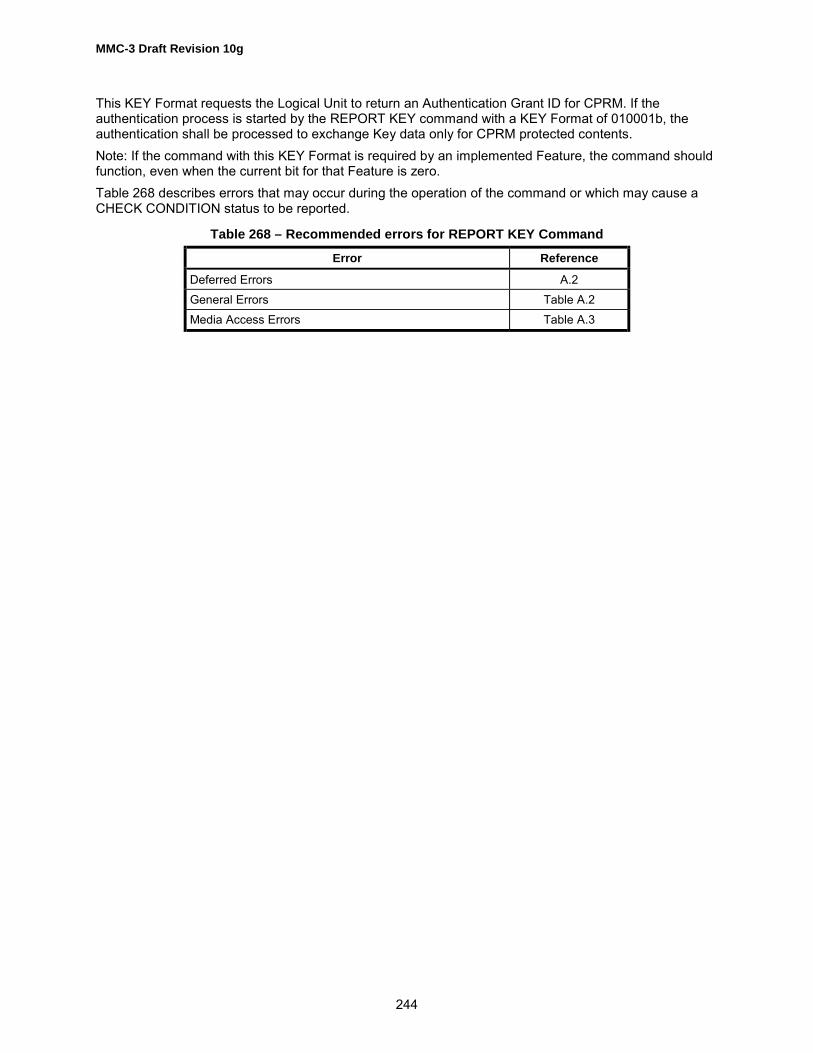
MMC-3 Draft Revision 10g
244
This KEY Format requests the Logical Unit to return an Authentication Grant ID for CPRM. If theauthentication process is started by the REPORT KEY command with a KEY Format of 010001b, theauthentication shall be processed to exchange Key data only for CPRM protected contents.Note: If the command with this KEY Format is required by an implemented Feature, the command shouldfunction, even when the current bit for that Feature is zero.Table 268 describes errors that may occur during the operation of the command or which may cause aCHECK CONDITION status to be reported.
Table 268 – Recommended errors for REPORT KEY Command
Error Reference
Deferred Errors A.2General Errors Table A.2Media Access Errors Table A.3
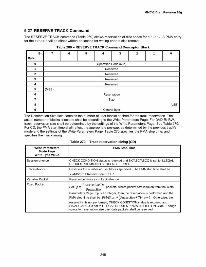
MMC-3 Draft Revision 10g
245
5.27 RESERVE TRACK CommandThe RESERVE TRACK command (Table 269) allows reservation of disc space for a track. A PMA entryfor the track shall be either written or cached for writing prior to disc removal.
Table 269 – RESERVE TRACK Command Descriptor Block
BitByte
7 6 5 4 3 2 1 0
0 Operation Code (53h)1 Reserved2 Reserved3 Reserved4 Reserved5 (MSB)6 Reservation7 Size8 (LSB)9 Control Byte
The Reservation Size field contains the number of user blocks desired for the track reservation. Theactual number of blocks allocated shall be according to the Write Parameters Page. For DVD-R/-RW,track reservation size shall be determined by the settings of the Write Parameters Page. See Table 270.For CD, the PMA start time shall reflect the appropriate pre-gap, as determined by the previous track�smode and the settings of the Write Parameters Page. Table 270 specifies the PMA stop time, andspecifies the Track sizing.
Table 270 – Track reservation sizing (CD)
Write ParametersMode Page
Write Type Value
PMA Stop Time
Session-at-once CHECK CONDITION status is returned and SK/ASC/ASCQ is set to ILLEGALREQUEST/COMMAND SEQUENCE ERROR
Track-at-once Reserves the number of user blocks specified. The PMA stop time shall bePMAStart servationSize+ +Re 2
Variable Packet Reserve behaves as in track-at-once.Fixed Packet
Set p servationSizePacketSize
=Re
packets, where packet size is taken from the Write
Parameters Page. If p is an integer, then the reservation is performed and thePMA stop time shall be ( )PMAStart PacketSize p+ + • −7 5 . Otherwise, thereservation is not performed, CHECK CONDITION status is returned andSK/ASC/ASCQ is set to ILLEGAL REQUEST/INVALID FIELD IN CDB. Enoughspace for reservation size user data packets shall be reserved.

MMC-3 Draft Revision 10g
246
Table 271 – TRACK reservation sizing (DVD-R/-RW)
Write ParametersMode Page
Write Type ValueReserved Track Size
Disc-at-once Reserves the number of user blocks specified. The Reserved Track shall beReservedTrackSize = ReservationSizewhere ReservationSize is a value that is specified in the CDB
Incremental Reserves the number of user blocks specified. The Reserved Track Size shall be
ReservedTrack = 16 • CellReservationSize + (NWA ̂0Fh)
16−(NWA ^0Fh) + 16
where ReservationSize is a value that is specified in the CDB. NWA is a NextWritable Address of invisible Track. ^ means mathematical AND. +16 means BSGA
Note: Cell (x) returns the least integral value greater than or equal to x.If the last track, defined in the PMA/RMA, is N, then the invisible track is assigned track number N+1. Atrack shall only be reserved from the beginning of the invisible track. After the reservation is done, thetrack number given to the new track is the current track number of the invisible track. The number of theinvisible track is increased by one following a reservation.For CD, if the Reservation Size is smaller than four seconds, excluding pre-gap length, the Logical Unitshall return CHECK CONDITION status.For DVD-R/-RW, the actual reserved size shall be raised to ECC block unit by the device. If ReservationSize field is set to 0, no reservation is done by device and shall not be considered an error.Reserving shall be allowed when the last track is invisible. When the last track is not invisible, shallgenerate a CHECK CONDITION status and set SK/ASC/ASCQ to ILLEGAL REQUEST/COMMANDSEQUENCE ERROR.For DVD-R/-RW, maximum reserved Tracks that can be reserved are limited to two at the same time.Attempting to reserve Track when two Empty/Partially recorded reserved tracks are already reserved, thecommand shall be terminated with CHECK CONDITION status and SK/ASC/ASCQ values are set toILLEGAL REQUEST/NO MORE TRACK RESERVATIONS ALLOWED.Attempting to reserve Track when there are less than 3 ECC blocks in the RMA, the command shall beterminated with CHECK CONDITION status and SK/ASC/ASCQ values are set to MEDIUMERROR/RMA/PMA IS FULL.For CD, Reserving a track when the Write Type is set to packet (See Table 348) shall cause the TDB(Track Descriptor Block) to be written.Table 272 describes errors that may occur during the operation of the command or which may cause aCHECK CONDITION status to be reported.
Table 272 – Recommended errors for RESERVE TRACK Command
Error Reference
Deferred Errors A.2
General Errors Table A.2Media Access Errors Table A.3Write Errors Table A.4

MMC-3 Draft Revision 10g
247
5.28 SCAN CommandThe SCAN command requests a fast-forward or fast-reverse scan operation starting from the ScanStarting Address. The Logical Unit shall respond to this command by scanning all the way to the end ofthe last audio track on the media.Like the PLAY AUDIO command, the SCAN command shall terminate the scan at the last audio track orupon receipt of a STOP PLAY/SCAN command. Upon receipt of the STOP PLAY/SCAN command theLogical Unit shall set the current address to the last address of data read from the media by the scanoperation. Subsequent Audio Play commands shall cause the Logical Unit to begin playing at the locationlast output by the SCAN command. If the Logical Unit receives a PAUSE/RESUME command with theresume bit clear, the Logical Unit shall pause. After that, if the Logical Unit receives a PAUSE/RESUMEcommand with the resume bit set, the Logical Unit shall resume audio play, not scan, from the addresswhere the audio pause occurred.If the Logical Unit receives a SCAN command during play or pause, the Logical Unit shall stop play orpause and perform Scan.If the Logical Unit encounters a data track, it shall terminate the scan.Upon receipt of a READ SUB-CHANNEL command during scan, the Logical Unit shall return an AudioStatus of 11h (Audio Play operation in Progress).The Initiator is required to issue PLAY AUDIO command immediately following a STOP PLAY/SCANcommand to resume the play audio operation at normal speed.
Table 273 – SCAN Command Descriptor Block
BitByte
7 6 5 4 3 2 1 0
0 OPERATION CODE (BAh)1 Reserved Direct Reserved RELADR
2 (MSB)3 Scan Starting Address Field45 (LSB)6 Reserved7 Reserved8 Reserved9 Type Reserved
10 Reserved11 Control
If the DIRECT bit is set to zero, the Logical Unit shall perform a fast-forward scan operation. A DIRECT bitof one causes a fast-reversed scan operation.The RELADR bit shall be set to zero.The Scan Starting Address specifies the address at that the audio fast scan operation shall begin. TheThe Type field (Table 274) specifies the format of the address contained in the Scan Starting AddressField.

MMC-3 Draft Revision 10g
248
Table 274 – Type field bit definitions
Bits 7 - 6
Address Type
0 0 Logical block address format0 1 MIN, SEC, and FRAME format (MSF)1 0 Track Number (TNO) format1 1 Reserved
With a Type field of 00h the Scan Starting address field specified in command bytes 2-5 are defined inTable 275.
Table 275 – Scan starting address field format-logical blocks
BitByte
7 6 5 4 3 2 1 0
2 (MSB)3 Scan Starting Logical Block Address Field45 (LSB)
With a Type field of 01h, bytes 2-5 specify the MSF address of the starting sector. See Table 276 below.
Table 276 – Scan Starting Address format - MIN, SEC, FRAME format
BitByte
7 6 5 4 3 2 1 0
2 Reserved3 CD-Absolute Time (MIN)4 CD-Absolute Time (SEC)5 CD-Absolute Time (FRAME)
The MIN, SEC and FRAME fields specify the relative running time from the beginning of the disc. TheMIN field has a range of 00d to 99d (00h to 63h). The SEC field ranges from 00d to 59d (00h to 3Bh). TheFRAME field has a range of 00h to 74d (00h to 4Ah). All MSF fields shall be binaryWith a Type field of 10h, bytes 2 - 5 specify a starting address of a specific Track Number (TNO). SeeTable 277 below
Table 277 – Scan Starting Address Format-Track Number (TNO)
BitByte
7 6 5 4 3 2 1 0
2 Reserved3 Reserved4 Reserved5 Track Number
The track number field specifies the track number in binary at that the scan operation begins. This fieldhas a range of 01h to 63h.

MMC-3 Draft Revision 10g
249
Scanning is a repeated play and jump operation. An example is the following implementation of forwardand reverse scan: Forward scan - Play six CD-DA blocks and then jump 190 CD-DA blocks in the forwarddirection. Reverse Scan - play six CD-DA blocks and then jump 150 CD-DA blocks (from the last block ofthe six) in the reverse direction.Table 278 describes errors that may occur during the operation of the command or which may cause aCHECK CONDITION status to be reported.
Table 278 – Recommended errors for SCAN operation
Error Reference
Deferred Errors A.2General Errors Table A.2Media Access Errors Table A.3

MMC-3 Draft Revision 10g
250
5.29 SEND CUE SHEET CommandA Session-at-once recording is written beginning with the Lead-in and continuing through the Lead-out.Only user data is sent with the write commands, so a guide structure is required by the Logical Unit inorder to control the recording process. This guide structure is called the cue sheet. The cue sheet isconstructed in the Initiator and sent to the Logical Unit.
Table 279 – SEND CUE SHEET Command Descriptor Block
BitByte
7 6 5 4 3 2 1 0
0 Operation Code (5Dh)1 Reserved2 Reserved3 Reserved4 Reserved5 Reserved6 (MSB)7 Cue Sheet Size8 (LSB)9 Control Byte
The Cue Sheet Size parameter is the number of bytes in the cue sheet to be sent to the Logical Unit.Prior to beginning the write process, the entire Cue Sheet shall be received by the Logical Unit. If theLogical Unit cannot accept and buffer the entire cue sheet, then CHECK CONDITION is returned andSK/ASC/ASCQ values are set to ILLEGAL REQUEST/INVALID FIELD IN CDB.If the Write Parameters Page does not have Write Type set to Session-at-once, then CHECKCONDITION status is returned and SK/ASC/ASCQ values are set to ILLEGAL REQUEST/COMMANDSEQUENCE ERROR.If the Write Mode in the Write Parameter Mode Page, is changed from session at once, the Q sheet maynot be available.
5.29.1 CUE SHEET FORMATThe Cue Sheet contains information required to specify the layout of a disc to be written, and shall besent to the Logical Unit via the SEND CUE SHEET command before writing data to the disc.The Cue Sheet format is shown in Table 280.
Table 280 – Cue Sheet format
Byte Number Cue Sheet Data
0 Mixture of... Information of absolute disc location, catalog Code,
(m-1)* 8 and ISRC (total m lines)
If the Catalog Code is to be recorded, it shall be described at the beginning of the Cue sheet.If the ISRC is to be recorded, it shall be described immediately preceding each Track�s information in theCue Sheet.For the Cue sheet, the Lead-out start time shall be the last entry.

MMC-3 Draft Revision 10g
251
5.29.2 Information of the absolute disc locationThe Logical Unit writes a disc according to this information. This information defines the followingparameters:1. Generation of Sub-channel P and Q channel.2. Format and block size of the data transferred by the WRITE command
Table 281 – Sample CUE SHEET
Byte Number CTL/ADR
TNO INDEX DATAFORM
SCMS ABSOLUTE TIME
MIN SEC FRAME
00 (Lead-in) 01h5 00h 00h1 01h5 00h 00h1 00h1 00h1
08 (TNO:01) 01h 01h 00h 01h 00h 00h 00h 00h10 (TNO:01) 2 01h 01h 01h 00h 00h 00h 02h 00h18 (TNO:02) 01h 02h 00h C0h 00h 07h 29h 71h20 (TNO:02) 01h 02h 01h C0h 00h 07h 31h 71h28 (TNO:03) 01h 03h 01h C0h 00h 14h 18h 03h30 (TNO:04)4 41h 04h 00h 10h 00h 19h 06h 62h38 (TNO:04) 41h 04h 01h 10h 00h 19h 09h 62h40 (TNO:05)4 41h 05h 00h 11h 00h 27h 37h 10h48 (TNO:05) 41h 05h 01h 10h 00h 27h 40h 10h50 (TNO:06) 01h 06h 00h 01h 80h6 38h 53h 23h58 (TNO:06) 01h 06h 01h 00h 80h6 38h 55h 23h60 (Lead-out) 01h5 AAh 01h3 01h5 00h 56h 37h 46h
NOTES:1. Always zero for Lead-in except when DATA FORM is set to 41h.2. The first information track on a disc is preceded by a pause encoding of 2-3 seconds. (If the first track is a Data
track, this track does not contain pause encoding, but always contains a "pause" of 2 seconds of pre-gap).3. Always 01h for Lead-out4. Pre-gap5. For the Lead-out area the DATA FORM shall be one. For Lead-in, DATA FORM shall be either 01h or 41h. The
control mode of the first track is specified. All data for both Lead-in and Lead-out shall be generated by the LogicalUnit except if DATA FORM 41h is selected for the Lead-in.
6. Copy
This information is composed of data units of 8 bytes (1 line). The information consists of three parts:1) The Lead-in area, and contains only one data unit.2) The Program area, that contains data units.3) The Lead-out area, and contains one or more data units.The data units in Program Area and Lead-out area are in Absolute Time order from the start time of index= 0 of the first track of the session.Each data unit of Program area and Lead-out area indicates that the value of each field (CONTROL,TNO, X, DATA FORM or ZERO) changes at the time shown in ABSOLUTE TIME field.

MMC-3 Draft Revision 10g
252
Table 282 – Cue Sheet Data
CTL/ADR
TNO INDEX DATAFORM
SCMS ABSOLUTE TIME
Min Sec Frame
01h 02h 01h C0h 00h 07h 31h 71h01h 03h 01h C0h 00h 14h 18h 03h
The above data unit indicates that the value of TNO changes from 02 to 03 when ABSOLUTE TIME is14:18:03 MSF.
5.29.2.1 Control/Address FieldThe CTL/ADR byte contains the Control field in the upper 4 bits and the ADR in the lower 4 bits. Refer toTable 283.
Table 283 – CTL/ADR byte
7 6 5 4 3 2 1 0
CTL Field ADR Field
5.29.2.2 CTL Field (upper 4 bits)The CTL (Control) field contains 4 bits that define the kind of information in a track. The definition isshown in Table 284.
Table 284 – Control Field
Bit 7 Bit 6 Bit 5 Bit 4 Definition
0 0 x 0 2 audio channels without pre-emphasis1 0 x 0 4 audio channels without pre-emphasis0 0 x 1 2 audio channels with pre-emphasis of 50/15 µs.1 0 x 1 4 audio channels with pre-emphasis of 50/15 µs.0 1 x 0 Data trackx x 0 x digital copy prohibitedx x 1 x digital copy permitted
The bits of the Control field (except for the copy bit) shall only be changed during an actual pause (Index= 00) of at least 2 seconds and during Lead-in area.
5.29.2.3 ADR Field (lower 4 bits)Table 285 defines the codes found in the ADR Field
Table 285 – ADR Field
Bit 3 Bit 2 Bit 1 Bit 0 Definition
0 0 0 1 start time at TNO/IDX0 0 1 0 CATALOG CODE0 0 1 1 ISRC CODE
All other codes are reserved for future use.

MMC-3 Draft Revision 10g
253
Control shall be the same for each entry associated with a particular track except for first part of pre-gap.
5.29.2.4 TNOThe TNO field indicates track number expressed in hexadecimal. Each track has a minimum length of 4seconds, not including the pause length preceding the track.
5.29.2.5 INDEX Field
The index number expressed in hexadecimal. The Logical Unit supports only 00h to 63h.
5.29.2.6 DATA FORMTable 286 defines the data form byte.
Table 286 – Data Form Byte
7 6 5 4 3 2 1 0
Data Form of Sub-channel
Data Form of Main Data
5.29.2.7 SCMS (Serial Copy Management System)Bit 7 of data form of 1 indicates that Copy bit of CONTROL field alternates for Serial Copy ManagementSystem (see Table 287). The other 7 bits (Reserved) are zero This bit is effective if Copy bit of the ControlCode is zero.
Table 287 – SCMS Byte
7 6 5 4 3 2 1 0
AlternateCopy bit
Reserved
5.29.2.8 DATA FORM OF MAIN DATAThe DATA FORM OF MAIN DATA field specifies the format of the main data to be sent by a WRITEcommand to write on the disc. Currently available data formats are 1.) CD-DA, 2.) CD-ROM mode 1, 3.)CD-ROM XA, and CD-I. For Lead-in and Lead-out area data are generated automatically except if DATAFORM is set to 41h
5.29.2.9 CD-DA Data Form
Table 288 defines a CD-DA Data Form for one frame.
Table 288 – CD (CD-DA)
Data Form Data of One Frame Data Size
00h 2 352 2 35201h 2 352 0

MMC-3 Draft Revision 10g
254
The CD-DA data format, Table 289, is as follows;
Table 289 – CD-DA Data format (1 Sample)
BitByte
7 6 5 4 3 2 1 0
n*4+0 (L Ch) L7 L6 L5 L4 L3 L2 L1 L0n*4+1 (L Ch) L15 L14 L13 L12 L11 L10 L9 L8n*4+2 (R Ch) R7 R6 R5 R4 R3 R2 R1 R0n*4+3 (R Ch) R15 R14 R13 R12 R11 R10 R9 R8
n = 0,1, - 5871 Second = 75 Frames1 Frame = 588 Samples1 Sample = 4 bytes (16 bits L, RCh)
5.29.2.10 CD-ROM mode 1 Form
Table 290 defines the form for CD-ROM mode 1.
Table 290 – CD-ROM mode 1
DataForm
Sync/Header
Data of One Frame EDC/ECC Area
DataSize
10h 16 2 2 048 1 288 2 2 04811h 16 3 2 048 1 288 3 2 35212h 16 2 2 048 3 288 2 2 04813h 16 3 2 048 3 288 3 2 35214h 16 2 2 048 2 288 2 0
5.29.2.11 CD-ROM XA, CD-I FormTable 291 defines the form for CD-ROM XA, CD-I.
Table 291 – CD-ROM XA, CD-I
DataForm
Sync/Header
SubHeader
Data of One Frame EDC/ECC Area
DataSize
20h Form 1 16 2 8 1 2 048 1 280 3 2 336Form 2 16 2 8 1 2 324 1 4 3 2 336
21h Form 1 16 3 8 1 2 048 1 280 3 2 352Form 2 16 3 8 1 2 324 1 4 3 2 352
22h Form 1 16 2 8 1 2 048 3 280 3 2 336Form 2 16 2 8 1 2 324 3 4 3 2 336
23h Form 1 16 3 8 1 2 048 3 280 3 2 352Form 2 16 3 8 1 2 324 3 4 3 2 352
24h Form 1 NA NA NA NA NAForm 2 16 2 8 2 2 324 2 4 2 0

MMC-3 Draft Revision 10g
255
Reserved Area: The Reserved Area contains 4 bytes that are reserved for quality control during the discproduction process. In case of Generate Zero, the Logical Unit generates zero data of 4 bytes for thisarea.
5.29.2.12 CD-ROM mode 2Figure 43 � CD-ROM Mode 2 defines the form for CD-ROM mode 2.
DataForm
Sync/Header
Data of One Frame DataSize
30h 16 2 2 336 1 2 33631h 16 3 2 336 1 2 35232h 16 2 2 336 3 2 33633h 16 3 2 336 3 2 35234h 16 2 2 336 2 0
Figure 43 – CD-ROM Mode 2Notes for all forms:1. Read Buffer: The data is sent by the Initiator.2. Generate Data: The Logical Unit generates the data in this area. The Initiator shall not send the datafor this area. All sectors in the program area shall have an associated write, even if all data for the sectoris to be generated by the Logical Unit. Zero bytes shall be transferred for such sectors.3. Ignore Buffer: The Logical Unit receives the data for this area from the Initiator with Write command.However, the Logical Unit ignores the data and generates data for this area.
5.29.2.13 Data Form of Sub-channelThe DATA FORM OF SUB-CHANNEL (Table 292) field specifies the format of the Sub-channel datastored in the inner buffer by WRITE command to write on the disc.
Table 292 – Data Form of Sub-channel
Data FormBit 7 Bit 6 Data of One Frame Data Size
0 0 96 *1 00 1 96 *2 961 0 Reserved1 1 24 Pack 3 24 Pack 3 24 Pack 3 24 Pack 3 96
Notes:1) Generate zero data2) RAW Data3) PACK DATA, Initiator sends packed data. The Logical Unit writes R-W. TheLogical Unit calculates and overwrites ECC, and performs Interleaving for each PACK.
Note: When this Data Form of Sub-channel is selected, along with 01h Data Form of Main Data, thisindicates that there is an attempt to write Raw P-W Sub-channel data in the Lead-in. Absolute Time fieldshould be set with the start address of the Lead-in, that can be read via a READ TRACK INFORMATIONcommand for track 0. In this case, the Data Block Type of the Write Parameters Page should be set to 2,3, or 4.

MMC-3 Draft Revision 10g
256
The Sub-channel data is placed at the end of each Frame of main data. Figure 44 shows the relationshipof Main Data and Sub-channel data.
Figure 44 – Location of Sub-channel DataThe P and Q Sub-channel information contained within the Sub-code Data shall be ignored. The P and QSub-channel information is generated by the Logical Unit and based on the content of the cue sheet.
5.29.2.14 Absolute TimeThe time shown at Min, Sec, and Frame gives the changing point of the CONTROL, TNO, X, DATAFORM or SCMS field. These values are given in absolute time scale.
5.29.2.15 Session Format
The Session Format is used for the identification of the type of disc. Refer to Table 248.
5.29.2.16 Pre-gapIf a Data track is preceded by a different mode of track (such as an audio track) or if the mode number ofCD-ROM changes, this Data track starts with an extended pre-gap. A pre-gap is placed at the head of aData track, also is belonging to the Data track. A pre-gap does not contain actual user data. The pre-gapis encoded as �pause.�An extended pre-gap is divided into two parts. The first part of the extended pre-gap has a minimum 1second of data, and it is encoded according to the data structure of previous track. The second part has aminimum 2 seconds data, and this data track is encoded according to the same data structure as theother parts.
5.29.2.17 Post-gapIf a Data track is followed by another kind of track (such as an audio track), this Data track ends with apost-gap. A post-gap is placed at the end of a Data track, and is part of the Data Track. A post-gap doesnot contain actual user data. The minimum length of post-gap is 2 seconds. The Logical Unit does notperform any action for a Post-gap.
5.29.2.18 Media Catalog NumberTable 293, Catalog Number, indicates the catalog number of a disc. The number uses UPC/EAN-code(BAR coding). If no catalog number is used, it shall be omitted. The format is as follows;
Main Data (2 352)
Subcode Data (96)
Main Data (2 352)
Subcode Data (96)
1 Frame
Data transferred by WRITE Command

MMC-3 Draft Revision 10g
257
Table 293 – Media Catalog Number (N1..N13)
CTL/ ADR Catalog Number
Byte 0 Byte 1 Byte 2 Byte 3 Byte 4 Byte 5 Byte 6 Byte 702h N1 N2 N3 N4 N5 N6 N702h N8 N9 N10 N11 N12 N13 00h
Note: The format of the data recorded in the Sub-channel area is not identical to that specified inthe Write Parameter Mode Page.
N1-N13 Catalog NumberCTL: 4 bits are zero.ADR: 0010bCatalog Number: ASCII 13 BYTES
5.29.2.19 ISRCTable 294, ISRC (International Standard Recording Code), is a code that is given to CD-DA tracks. If noISRC is used, it shall be omitted. If a track has no ISRC, it is not written in the Cue Sheet.
Table 294 – ISRC (I1..I12)
CTL/ ADR
ISRC(International Standard Recording Code)
byte 0 byte 1 byte 2 byte 3 byte 4 byte 5 byte 6 byte 7x3h TNO I1 I2 I3 I4 I5 I6x3h TNO I7 I8 I9 I10 I11 I12
Note: The format of the data recorded in the Sub-channel area is not identical to that specified in theWrite Parameter Mode Page.CTL: 4 bits of Control code are the same as that of disc location of the specified trackADR: 0011bTNO: Track number in HEX.12 letters ISRC (On the Cue Sheet, I1-I12 shall be described by valid ASCII characters. See Table 294for valid codes.I1-I2: Country CodeI3-I5: Owner CodeI6-I7: Year of recordingI8-I12: Serial NumberTable 295 describes errors that may occur during the operation of the command or which may cause aCHECK CONDITION status to be reported. Since this command contains no background activity,deferred errors do not apply.
Table 295 – Recommended Sense Key, ASC and ASCQ SEND CUE SHEET Command
Error Reference
General Errors Table A.2

MMC-3 Draft Revision 10g
258
5.30 SEND DVD STRUCTURE CommandThe SEND DVD STRUCTURE command (Table 296) provides a means for the Initiator to transfer DVDSTRUCTURE data to the Logical Unit.
Table 296 – SEND DVD STRUCTURE Command Descriptor Block
BitByte
7 6 5 4 3 2 1 0
0 Operation Code (BFh)1 Reserved Reserved2 Reserved3 Reserved4 Reserved5 Reserved6 Reserved7 Format8 (MSB) Structure Data Length9 (LSB)
10 Reserved11 Control
The Format field (Table 297) indicates the type of information to be sent to the device. When a SENDDVD STRUCTURE command is issued on non-DVD media for Format codes 00h �BFh, this commandshall be terminated with CHECK CONDITION status and SK/ASC/ASCQ values are set to ILLEGALREQUEST/ CANNOT READ MEDIUM � INCOMPATIBLE FORMAT. When the device/media does notsupport the specified format code, the command shall be terminated with a CHECK CONDITION statusand SK/ASC/ASCQ values are set to ILLEGAL REQUEST/INVALID FIELD IN CDB.
Table 297 – Format Field Definition
Format Code Data Description
00h � 03h Reserved04h User Specific Data Send User Specific Data to the RMD cache05h Copyright Management Send data to CPR_MAI in data area cache. (CPM,
CGMS, ADP_TY)06h � 0Eh Reserved
0Fh Timestamp Send Timestamp data to the RMD cache10h � 2Fh Reserved
30h Disc Control Block Send a Disc Control Block31h � BFh Reserved
C0h Write Protection Send PWP statusC1h � FFh Reserved
The DVD-R device shall implement the cache memory for DVD STRUCTURE data.The cached RMD can be read by using the READ DVD STRUCTURE command.

MMC-3 Draft Revision 10g
259
The Structure Data Length field specifies the length in bytes of the DVD STRUCTURE data to betransferred from the Initiator to the Logical Unit after the CDB is transferred. A Structure Data Length fieldof zero indicates that no data shall be transferred. This condition shall not be considered an error.
5.30.1 User Specific DataTable 298 defines the response data format for User Specific Data, Format code 04h
Table 298 – SEND DVD STRUCTURE Data Format (Format Code = 04h)
BitByte
7 6 5 4 3 2 1 0
0 (MSB) DVD STRUCTURE Data Length1 (LSB)2 Reserved3 Reserved
DVD-R User Specific Data0 (MSB)… User Specific Data
2047 (LSB)
The DVD STRUCTURE Data Length field specifies the length in bytes of the User Specific Data to follow.A DVD Structure Data Length field of zero indicates that no User Specific Data shall be transferred. Thiscondition shall not be considered an error.The User Specific Data field contains user specific data. This data shall be used to specify the RMD Field2, and when writing Lead-in the contents of this field shall also be written in Disc manufacturinginformation field of Lead-in or Border-in.
5.30.2 Copyright Management InformationTable 299 describes the response data format for Copyright Management Information, format code 05h.
Table 299 – SEND DVD STRUCTURE Data Format (Format Code = 05h)
BitByte
7 6 5 4 3 2 1 0
0 (MSB) DVD STRUCTURE Data Length1 (LSB)2 Reserved3 Reserved
Copyright Management Information in data area0 CPR_MAI1 Reserved2 Reserved3 Reserved

MMC-3 Draft Revision 10g
260
The DVD STRUCTURE Data Length field specifies the length in bytes of the Copyright Management datato follow. A DVD Structure Data Length field of zero indicates that no Copyright Management data shallbe transferred. This condition shall not be considered an error.The definition of the CPR_MAI field depends on the mounted media. The CPR_MAI field definition isshown in Table 300.
Table 300 – CPR_MAI Field Definitions
BitMedia
7 6 5 4 3 2 1 0
DVD-R, ver1.0
DVD-RW,ver 1.0
CPM Resvd CGMS Reserved
DVD-RAMVer.1.0/2.1DVD-R forAuthoringVer .2.0
Reserved
DVD-R forGeneral, ver
2.0, DVD-RW, ver 1.1
andDVD+RW
Reserved ADP_TY Reserved
If the CPM bit is set to 0, shall indicate that this sector contains no copyrighted material. If the CPM bit isset to 1, shall indicate that this sector contains copyrighted material. If this structure is not sent, thedefault value of the CPM bit shall be 0.When the CPM bit is set to 0, the CGMS field shall be set to 00b. When the CPM bit is set to 1, theCGMS field shall be set as shown in Table 301.
Table 301 – CGMS Field Values
CGMS Definition
00b Copying is permitted without restriction
01b Reserved
10b One generation of copies may be made
11b No copying is permitted
The identical CGMS value of CPR_MAI in data area shall match with this format following write operation.The ADP_TY field is defined for DVD-RW Ver.1.1, DVD-R for General Ver. 2.0, and DVD+RW media. Ifthe sector contains materials defined in DVD Specifications for Read-Only Disc Part 3 VIDEOSPECIFICATIONS, the ADP_TY field shall be set to 01b. If the sector contains no such data, ADP_TYfield shall be set to 00b. All other values of ADP_TY are reserved.
Note: A value of each field may not be stable at the first and last 16 sectors of each recordingextent due to the nature of recording method for DVD-R/-RW media.

MMC-3 Draft Revision 10g
261
5.30.3 TimestampThe format of Timestamp field is structured as shown in Table 345. This format code is used to setUnique Disc Identifier field of RMD (Recording Management Data) for DVD-R. This time stamp data mayalso be used in OPC related field in RMD Field 1 and may help the judgement to do OPC.The time should be current UTC (Universal Coordinated Time) 24 hour clock.
Table 302 – SEND DVD STRUCTURE Data Format (Format Code = 0Fh)
BitByte
7 6 5 4 3 2 1 0
0 (MSB) DVD STRUCTURE Data Length1 (LSB)2 Reserved3 Reserved
DVD Timestamp Data0 Reserved1 Reserved2 Reserved3 Reserved4 (MSB)5 Year67 (LSB)8 (MSB) Month9 (LSB)
10 (MSB) Day11 (LSB)12 (MSB) Hour13 (LSB)14 (MSB) Minute15 (LSB)16 (MSB) Second17 (LSB)
The DVD STRUCTURE Data Length field specifies the length in bytes of the DVD Timestamp Data tofollow. A DVD Structure Data Length field of zero indicates that no DVD Timestamp Data shall betransferred. This condition shall not be considered an error.The Year field shall specify the year that coded as ASCII in the range �0001� to �9999�.The Month field shall specify the month of the year that coded as ASCII in the range �01� to �12�.The Day field shall specify the day of the month that coded as ASCII in the range �01� to �31�.The Hour field shall specify the hour of the day that coded as ASCII in the range �00� to �23�.The Minute field shall specify the minute of the hour that coded as ASCII in the range �00� to �59�.The Second field shall specify the second of the minute that coded as ASCII in the range �00� to �59�.

MMC-3 Draft Revision 10g
262
5.30.4 Disc Control BlockTable 303 defines data format code 30h.
Table 303 – SEND DVD STRUCTURE Data Format (Format Code = 30h)
BitByte
7 6 5 4 3 2 1 0
0 (MSB) DVD STRUCTURE Data Length1 (LSB)2 Reserved Erase
3 Reserved
Disc Control Block0… Disc Control BlockN
The Structure Data Length field shall indicate the number of bytes following this field.The Erase bit, when set to zero, shall indicate that the Disc Control Block be written to the media. Whenset to one, it shall indicate that the Disc Control Block on the medium, with a Content Descriptormatching the one sent, shall be erased. When erasing a DCB, at least the first four bytes shall be sent.The Logical Unit shall not record any DCB unknown to the Logical Unit.The Disc Control Block field is defined in the DVD+RW 4.7 Gbytes Basic Formats Specifications. If aDisc Control Block, with fewer than 32 768 bytes is sent, the Logical Unit shall pad the Disc Control Blockwith 00h bytes.
5.30.5 Write ProtectionTable 304 defines data format code C0h.
Table 304 – SEND DVD STRUCTURE Data Format (Format Field = C0h)
BitByte
7 6 5 4 3 2 1 0
0 (MSB) Structure Data Length1 (LSB)2 Reserved3 Reserved
Write Protection Data
4 Reserved PWP Reserved5 Reserved6 Reserved7 Reserved
The DVD Structure Data Length field shall indicate the number of bytes following this field.The Persistent Write Protection (PWP) bit of one indicates that the medium surface shall be set to writeprotected status. The PWP bit of zero indicates that the medium surface shall be set to write permittedstatus.

MMC-3 Draft Revision 10g
263
Table 305 describes errors that may occur during the operation of the command or which may cause aCHECK CONDITION status to be reported.
Table 305 – Recommended errors for SEND DVD STRUCTURE Command
Error Reference
Deferred Errors A.2General Errors Table A.2Media Access Errors Table A.3

MMC-3 Draft Revision 10g
264
5.31 SEND EVENT CommandThe SEND EVENT command requests the Logical Unit to process an event for the Initiator. The eventshould be one that the Initiator had received from an earlier GET EVENT/STATUS NOTIFICATIONcommand but not handled by the Initiator. If a Logical Unit has received a persistent prevent, it shallreport events via the GET EVENT/STATUS NOTIFICATION command instead of processing themdirectly. For example if a user pushes an independent play button on the front panel while the Logical Unitis in a persistent prevent state, the play would not be performed and instead the request shall be reportedto the Initiator by a GET EVENT/STATUS NOTIFICATION command. Such events may include frontpanel button presses, etc. When such a request is received by the Initiator, it should complete anyoperations in progress and process the event by emulating the button�s functionality via commands orsending the event back to the Logical Unit using the SEND EVENT command.The Media Status Class Events reported to the Initiator shall not be sent back to the Logical Unit usingthe SEND EVENT command. Only events of Class External Request (Class 3) shall be sent via theSEND EVENT command.
Table 306 – SEND EVENT Command Descriptor Block
BitByte
7 6 5 4 3 2 1 0
0 Operation Code (5Dh)1 Reserved Reserved IMMED2 Reserved3 Reserved4 Reserved5 Reserved6 Reserved7 Reserved8 (MSB) Parameter List Length9 (LSB)
10 Reserved119 Control Byte
An Immediate (IMMED) bit of one indicates that status shall be returned as soon as the CommandPacket has been validated. The actual operation specified by the Event Parameter shall be processedafter the status has been reported to the Initiator. The IMMED bit shall be set to 1h.The Parameter List Length field specifies the length in bytes of the Event parameter list that shall betransferred from the Initiator to the Logical Unit after the Command Packet is transferred. A parameter listlength of zero indicates that no data shall be transferred. This condition shall not be considered as anerror.The Logical Unit shall terminate the command with CHECK CONDITION status if the Event parameter listlength results in the truncation of Event parameter data. SK/ASC/ASCQ values shall be set to ILLEGALREQUEST/PARAMETER LIST LENGTH ERROR.

MMC-3 Draft Revision 10g
265
The Logical Unit shall terminate the command with CHECK CONDITION status and SK/ASC/ASCQvalues are set to ILLEGAL REQUEST/INVALID FIELD IN PARAMETER LIST, and shall not take anyaction directed by the event specified for the following conditions:1. If the Initiator sets any unreserved field in the Event parameter header to an unsupported value.2. If an Initiator sends an Event parameter list with a Event Data Length not equal to the length returned
by the GET EVENT/STATUS NOTIFICATION command for the specified event class.3. If the Initiator sends an invalid value for any Event parameter.
Table 307 – Event Parameter Header
BitByte
7 6 5 4 3 2 1 0
0 (MSB) Event Parameter Length1 (LSB)2 Reserved Reserved Notification Class (1h)3 Reserved
The Event Parameter Length field specifies the number of bytes that follow the Event Parameter Lengthfield. Notification Class field specifies the class of Event being sent to the Logical Unit. This field shallcontain a 1h.
Table 308 – Operational Change/Notification Parameter Data
BitByte
7 6 5 4 3 2 1 0
0 Reserved Operational Event1 Persistent
PreventedReserved Operational Status
2 (MSB) Operational Request Code3 (LSB)
The Operational Event field indicates the type of operation to be performed.
Table 309 – Operational Event Field
Code Event Description
0h No Change (NoCHge) No request shall be processed by the Logical Unit1h Operational Change Request Initiator requests Logical Unit to process the Operational
Request2h - Fh Reserved
The Persistent Prevented bit is reserved and shall be ignored.The Operational Status field is reserved and shall be ignored. This field may contain the non-zero valuereported to the Initiator.Operational Request Code field contains the actual requested operation. See Table 85 for codedescriptions.

MMC-3 Draft Revision 10g
266
Table 310 describes errors that may occur during the operation of the command or which may cause aCHECK CONDITION status to be reported.
Table 310 – Recommended errors for SEND EVENT Command
Error Reference
Deferred Errors A.2General Errors Table A.2Media Access Errors Table A.3

MMC-3 Draft Revision 10g
267
5.32 SEND KEY CommandThe SEND KEY command, Table 311, provides data necessary for authentication and for generating aBus Key for the DVD Logical Unit.This command, in conjunction with REPORT KEY command, is intended to perform authentication forLogical Units that conform to DVD Content Protection scheme and to generate a Bus Key as the result ofauthentication.
Table 311 – SEND KEY Command Descriptor Block
BitByte
7 6 5 4 3 2 1 0
0 Operation Code (A3h)1 Reserved Reserved2 Reserved3 Reserved4 Reserved5 Reserved6 Reserved7 Reserved8 (MSB) Parameter List Length9 (LSB)
10 AGID Key Format11 Control
The KEY Format field (Table 312) indicates the type of information that is to be sent to the Initiator.The AGID field is described in the REPORT KEY command.
Table 312 – Key Format Code definitions for SEND KEY Command
Key Format Sent Data Description AGID Use
000001b Challenge Key Accepts a Challenge Key Valid AGID required000011b KEY2 Accepts a KEY2000110b RPC Structure Set Region Reserved & Ignored111111b None Invalidate Specified AGID.
Invalidating an invalid AGID shall not beconsidered an error.An AGID that has not been granted shall beconsidered invalid.
Valid AGID required
All othervalues
Reserved

MMC-3 Draft Revision 10g
268
The Key Formats are defined in Table 313, Table 314, and Table 315.
Table 313 – SEND KEY Parameter List (KEY Format field =000001b)
BitByte
7 6 5 4 3 2 1 0
0 (MSB) SEND KEY Parameter List Length (0Eh)1 (LSB)2 Reserved3 Reserved
Challenge Key Value
0 (MSB): Challenge Key Value9 (LSB)
10 Reserved11 Reserved
Challenge Key is sent to the DVD Logical Unit to get corresponding KEY1 from the DVD Logical Unit tointerrogate conformity with DVD Content Protection scheme.
Table 314 – SEND KEY Parameter List (KEY Format field =000011b)
BitByte
7 6 5 4 3 2 1 0
0 (MSB) SEND KEY Parameter List Length (0Ah)1 (LSB)2 Reserved3 Reserved
KEY2
0 (MSB): KEY2 Value4 (LSB)5 Reserved6 Reserved7 Reserved
The KEY2, generated external to the DVD Logical Unit, is sent to the DVD Logical Unit to determine itsconformity with DVD Copy Protection scheme. The KEY 2 value shall be used for the second input togenerate a Bus Key in the DVD Logical Unit.When the KEY2 value sent does not conform to the DVD Copy Protection scheme, this command shallbe terminated with a CHECK CONDITION status and SK/ASC/ASCQ values are set to ILLEGALREQUEST/COPY PROTECTION KEY EXCHANGE FAILURE - AUTHENTICATION FAILURE.When the SEND KEY command with KEY Format = 000011b terminates with CHECK CONDITIONstatus, the retry of authentication shall be performed from the beginning.

MMC-3 Draft Revision 10g
269
Table 315 – SEND KEY Parameter List (KEY Format field =000110b)
BitByte
7 6 5 4 3 2 1 0
0 (MSB) SEND KEY Parameter List Length (06h)1 (LSB)2 Reserved3 Reserved
RPC Structure0 Preferred Logical Unit Region Code1 Reserved2 Reserved3 Reserved
Preferred Logical Unit Regional Code is sent to the DVD Logical Unit to make the Logical Unitregionalized. The Preferred Logical Unit Region Code specifies a single region in which the disc can beplayed. Each bit represents one of eight regions. If a bit is cleared in this field, the disc can be played inthe corresponding region. If a bit is set in this field, the disc cannot be played in the corresponding region.Exactly one bit of the Preferred Logical Unit Region Code shall contain a zero.If the Logical Unit does not support setting of the Region, or the Region is no longer changeable, then thiscommand shall be terminated with CHECK CONDITION status and SK/ASC/ASCQ values shall be set toDRIVE REGION MUST BE PERMANENT/REGION RESET COUNT ERROR.Table 316 describes errors that may occur during the operation of the command or which may cause aCHECK CONDITION status to be reported.
Table 316 – Recommended errors for SEND KEY Command
Error Reference
Deferred Errors A.2General Errors Table A.2Media Access Errors Table A.3

MMC-3 Draft Revision 10g
270
5.33 SEND OPC INFORMATION CommandThis command is used to restore the Optimum Power Calibration (OPC) (Table 317) values to the LogicalUnit for a specific disc. It is used in combination with the READ DISC INFORMATION command (sub-clause 5.19).
Table 317 – SEND OPC INFORMATION Command Descriptor Block
BitByte
7 6 5 4 3 2 1 0
0 Operation Code (54h)1 Reserved Reserved DoOpc
2 Reserved3 Reserved4 Reserved5 Reserved6 Reserved7 (MSB) Parameter List Length8 (LSB)9 Control
The Parameter List Length shall be set to reflect the number of the parameter bytes to be transferred.The Parameter List Length shall be an integral multiple of eight, (2 byte OPC Speed and 6 bytes of OPCvalue). This can be extended with a second OPC Speed and Value. In this case the length is 16.The DoOpc bit, when set to one, indicates the Logical Unit shall perform an OPC operation to set theOPC values for the current speed. These OPC values shall become current. Parameter List length shouldbe set to zero. When the bit is set to zero, the Logical Unit sets OPC values to those sent in theParameter List.A Parameter List Length field of zero shall not be considered an error condition.The Initiator shall transfer zero or more OPC tables.The transfer length shall be 8X (the number of OPC table entries).The format of the OPC Data to be transferred is shown in Table 318.
Table 318 – SEND OPC INFORMATION Parameter List
BitByte
7 6 5 4 3 2 1 0
0 (MSB) OPC Speed in KBytes per Second1 (LSB)2 (MSB)34 OPC Value567 (LSB)

MMC-3 Draft Revision 10g
271
Table 319 describes errors that may occur during the operation of the command or which may cause aCHECK CONDITION status to be reported.
Table 319 – Recommended errors for SEND OPC INFORMATION Command
Error Reference
Deferred Errors A.2General Errors Table A.2Media Access Errors Table A.3Write Errors Table A.4

MMC-3 Draft Revision 10g
272
5.34 SET CD SPEED CommandThe SET CD SPEED (Table 320) command is used to set read speed and write speed and onlyapplicable to CD-R/RW Logical Unit. Note that PLAY AUDIO Commands may not use the speed set bythis command.
Table 320 – SET CD SPEED Command
BitByte
7 6 5 4 3 2 1 0
0 OPERATION CODE (BBh)1 Reserved Rotational Control2 (MSB) Logical Unit Read Speed (Kbytes/sec)3 (LSB)4 (MSB) Logical Unit Write Speed (Kbytes/sec)5 (LSB)6 Reserved7 Reserved8 Reserved9 Reserved
10 Reserved11 Control
The Logical Unit Read Speed and Write Speed parameters contain the requested Data rates the LogicalUnit should use.Initiator shall set one of the values of Logical Unit Write Speed Performance Descriptor in CD/DVDCapabilities & Mechanical Status Mode Page (2Ah) to Rotational Control field and Logical Unit WriteSpeed field.The Logical Unit is to select the Logical Unit Read Speed specified or any higher rate. A value of FFFFhcauses the Logical Unit Read Speed or the Logical Unit Write Speed to be set for optimal performancesupported. If the Logical Unit is requested to write at the speed that is not listed in the Logical Unit WriteSpeed Performance Descriptor, the Logical Unit shall select any slower Logical Unit Write Speed. Thiscondition is not regarded as an error condition. If the Logical Unit is requested to write at the lower speedthan the Logical Unit�s slowest speed, the Logical Unit may return CHECK CONDITION status andSK/ASC/ASCQ values are set to ILLEGAL REQUEST/INVALID FIELD IN CDB or select an appropriateLogical Unit Write Speed.Note: Logical Unit should return an error if current write mode is not packet write and buffer under-runfree recording is not supported.The Rotational Control field defines the operations that are defined in Table 321.
Table 321 – Rotational Control field definition
Value Description
0h CLV recording1h CAV recordingOthers Reserved
In case of CAV recording, Logical Unit Write Speed shall be specified with the speed at most innerprogram area of the disc. Assume that the outer most radius: 79min 59sec 74frames.

MMC-3 Draft Revision 10g
273
The Logical Unit keeps the actual write speed setting till the current disc is ejected. When the disc ischanged to another one and it does not support the write speed that was set for the previous media, theLogical Unit may select an appropriate write speed to the current medium. It is recommended that theInitiator should set the write speed upon the media change.Table 322 describes errors that may occur during the operation of the command or which may cause aCHECK CONDITION status to be reported.
Table 322 – Recommended errors for SET CD SPEED Command
Error Reference
Deferred Errors A.2General Errors Table A.2Media Access Errors Table A.3

MMC-3 Draft Revision 10g
274
5.35 SET READ AHEAD CommandThe SET READ AHEAD command (Table 323) requests that the Logical Unit perform Read AheadCaching operations from the Read-Ahead Logical Block Address when the Logical Unit encounters theTrigger Logical Block Address during its internal Read Ahead Caching operation.If this command is received by the DVD Logical Unit when data after the Trigger Logical Block Addressand before the Read Ahead Logical Block Address is contained in its cache, that data should bediscarded and Read Ahead Caching restarted from the specified Read Ahead Logical Block Address.Sectors after the Trigger LBA (Not including the Trigger LBA) should be skipped. The Initiator normallyreads the data for both the Trigger and Read Ahead LBA. The sectors between these addresses(exclusive) are normally not read by the Initiator.The Read-Ahead operation shall be performed in background, i.e. the Logical Unit shall accept acommand during the Read-Ahead operation.
Table 323 – SET READ AHEAD Command
BitByte
7 6 5 4 3 2 1 0
0 OPERATION CODE (A7h)1 Reserved Reserved2 (MSB)3 Trigger Logical Block Address45 (LSB)6 (MSB)7 Read Ahead Logical Block Address89 (LSB)
10 Reserved11 Control
Table 324 describes errors that may occur during the operation of the command or which may cause aCHECK CONDITION status to be reported.
Table 324 – Recommended errors for SET READ AHEAD Command
Error Reference
Deferred Errors A.2General Errors Table A.2Media Access Errors Table A.3

MMC-3 Draft Revision 10g
275
5.36 SET STREAMING CommandThe SET STREAMING command (Table 325) provides a way for the Initiator to indicate to the LogicalUnit that the application has specific request or requirements for Logical Unit performance. The LogicalUnit may utilize the Initiator supplied information to change mechanical or logical operation. For example,the spindle motor speed may be adjusted downward for lower data rates to help avoid buffer overrun(during reading) or buffer underrun (during writing) followed by a consequent rotational delay. Theperformance setting is persistent and remains until a new descriptor is sent. The setting only applies tothe extent identified by the Start and End LBA field. Only zero or one, performance extents shall be validat any time.The SET STREAMING command affects the READ and WRITE Command operation, and may affectother commands, e.g. BLANK and FORMAT UNIT.If the SET STREAMING command is used to set performance, the Logical Unit may disable read andwrite reallocation in the specified region in order to meet the performance criteria.
Table 325 – SET STREAMING Command Descriptor Block
BitByte
7 6 5 4 3 2 1 0
0 Operation Code (B6h)1 Reserved Reserved2 Reserved3 Reserved4 Reserved5 Reserved6 Reserved7 Reserved8 Reserved9 (MSB) Parameter List Length
10 (LSB)11 Control
The Initiator shall send a performance descriptor during the data phase of this command. ThePerformance Descriptor shall be sent in the format shown in Table 326.

MMC-3 Draft Revision 10g
276
Table 326 – Performance Descriptor
BitByte
7 6 5 4 3 2 1 0
0 Reserved WRC RDD Exact RA1 Reserved2 Reserved3 Reserved4 (MSB)5 Start LBA67 (LSB)8 (MSB)9 End LBA
1011 (LSB)12 (MSB)13 Read Size1415 (LSB)16 (MSB)17 Read Time1819 (LSB)20 (MSB)21 Write Size2223 (LSB)24 (MSB)25 Write Time2627 (LSB)
The Write Rotation Control (WRC) field specifies the type of the medium rotation control to write. SeeTable 118. If Logical Unit does not support the write rotation control mode specified, the Logical Unit shallgenerate CHECK CONDITION status and SK/ASC/ASCQ values are set to ILLEGAL REQUEST/INVALIDFIELD IN PARAMETER LIST.The RDD (Restore Logical Unit Defaults) bit, when set to zero, indicates the remaining fields are valid.When set to one, it shall indicate that the Logical Unit is to return to its default performance settings andthe remaining fields in this descriptor shall be ignored. Read and Write reallocation ability shall berestored to the operation specified by the Read/Write Error Recovery Mode Page.The Exact bit, when set to zero, shall indicate that the Logical Unit shall set its internal configuration tomatch the parameters as best as possible. No errors shall occur. When set to one, the Logical Unit shallset its internal configuration to support the requested parameters. If the Logical Unit cannot perform as

MMC-3 Draft Revision 10g
277
requested, it shall generate CHECK CONDITION status and SK/ASC/ASCQ values are set to ILLEGALREQUEST/ INVALID FIELD IN PARAMETER LIST.The RA (Random Access) bit, when set to zero, allows the Logical Unit to independently set the read andwrite speeds. When set to one, directs the Logical Unit to set its performance settings for the optimizedsettings for random changes between reading and writing by the Initiator. For example, a CD recorderthat can record at 2X and read at 6X may choose to limit reading to 2X if the RA bit was set to one.The Start LBA field is the first logical block for which the performance request is being made.The End LBA field is the last logical block for which the performance request is being made.The data rate to be delivered for reading is (Read Size)/(Read Time).The Read Size field shall indicate the number of kilobytes the Initiator expects to be delivered per periodof Read Time when the Initiator�s requests for data occur sufficiently fast.The Read Time field shall indicate the amount of time, in milliseconds, over that the Read Size isexpected to be read. The Initiator may set these two fields by setting Read Size to the size of itsapplication�s buffer and the Read Time to the amount of time it takes to empty that buffer.The Write Size field shall be set to the number of kilobytes to be written per Write Time.The Write Time field shall indicate the amount of time, in milliseconds, over that the Write Size isexpected to be written.In many cases, the Write Size and Write Time fields should be set to match the corresponding Readfields. If not, the Initiator may set the Write Size to the size of its application buffer and the Write Time tothe time it takes to fill that buffer.Table 327 describes errors that may occur during the operation of the command or which may cause aCHECK CONDITION status to be reported.
Table 327 – Recommended errors for SET STREAMING Command
Error Reference
Deferred Errors A.2General Errors Table A.2Media Access Errors Table A.3Write Errors Table A.4
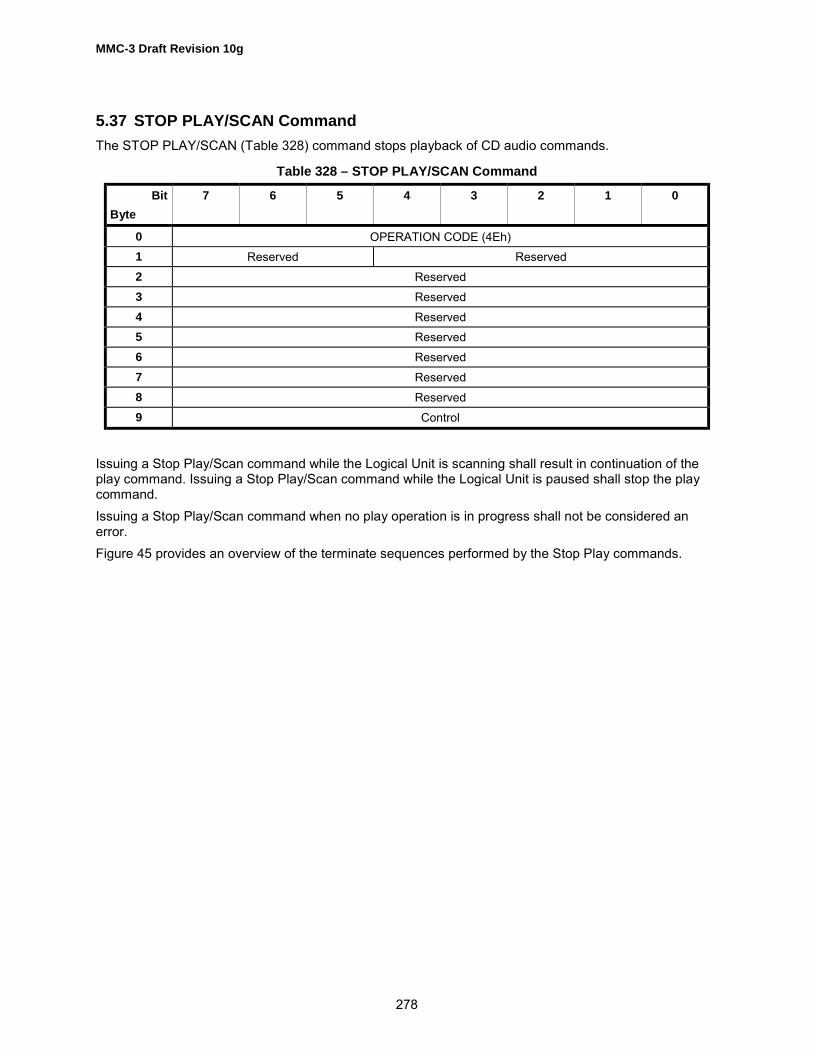
MMC-3 Draft Revision 10g
278
5.37 STOP PLAY/SCAN CommandThe STOP PLAY/SCAN (Table 328) command stops playback of CD audio commands.
Table 328 – STOP PLAY/SCAN Command
BitByte
7 6 5 4 3 2 1 0
0 OPERATION CODE (4Eh)1 Reserved Reserved2 Reserved3 Reserved4 Reserved5 Reserved6 Reserved7 Reserved8 Reserved9 Control
Issuing a Stop Play/Scan command while the Logical Unit is scanning shall result in continuation of theplay command. Issuing a Stop Play/Scan command while the Logical Unit is paused shall stop the playcommand.Issuing a Stop Play/Scan command when no play operation is in progress shall not be considered anerror.Figure 45 provides an overview of the terminate sequences performed by the Stop Play commands.

MMC-3 Draft Revision 10g
279
Figure 45 – Stop Play/Play Audio/Audio Scan/Pause/Resume SequencingTable 329 describes errors that may occur during the operation of the command or which may cause aCHECK CONDITION status to be reported.
Table 329 – Recommended errors for STOP PLAY/SCAN Command
Error Reference
Deferred Errors A.2General Errors Table A.2Media Access Errors Table A.3
SCAN
INITIALIZED
PLAY
PAUSED
Scan
Scan
Scan
Pause Pause
Resume or Play
Stop
Stop or End of Track
Play
Play
Play or Resume
Stop or End of Track

MMC-3 Draft Revision 10g
280
5.38 SYNCHRONIZE CACHE CommandThe SYNCHRONIZE CACHE command is shown in Table 330.This command assures all remaining data in the data buffer has been written to the media. Logical blocksare not necessarily removed from the cache memory as a result of the cache flush operation.If the data buffer is empty, issuing this command shall result in no data being written to the physicalmedia. This action shall not be considered an error. Normal status shall be presented at the completionof the action.
Table 330 – SYNCHRONIZE CACHE Command
BitByte
7 6 5 4 3 2 1 0
0 Operation Code (35h)1 Reserved Reserved IMMED RELADR2 (MSB)3 Logical Block Address45 (LSB)6 Reserved7 (MSB) Number of Blocks8 (LSB)9 Control
RelAdr (Relative Address) is not used by CD/DVD Logical Units and shall be set to zero.An IMMED (Immediate) bit of one indicates that the Logical Unit shall return status when the commanddescriptor block has been validated. An Immediate bit of zero indicates that the status shall not bereturned until the operation has been completed. If the Immediate bit is one and the Logical Unit does notsupport immediate operation, then the command shall terminate with CHECK CONDITION status andSK/ASC/ASCQ values shall be set to ILLEGAL REQUEST/INVALID FIELD IN CDB.The Logical Unit may ignore the Logical Block Address field.The Number of Blocks field specifies the total number of contiguous logical blocks within the range. ANumber of Blocks field, equal to 0, indicates that all remaining logical blocks on the Logical Unit shall bewithin the range. The Logical Unit may ignore this field.A logical block within the specified range that is not in cache memory is not considered an error.Table 331 describes errors that may occur during the operation of the command or which may cause aCHECK CONDITION status to be reported.
Table 331 – Recommended errors for SYNCHRONIZE CACHE Command
Error Reference
Deferred Errors A.2General Errors Table A.2Media Access Errors Table A.3Write Errors Table A.4

MMC-3 Draft Revision 10g
281
5.39 WRITE (10) CommandThe Write (10) command (Table 332) requests that the Logical Unit write data transferred from theinitiator to the currently mounted medium. In most cases, the Logical Unit shall use the Write ParametersPage to determine its operating behavior. The description of the behavior, described in this sub-clause,applies only to Multimedia Logical Units or Logical Units. For the write behavior of other Logical Unitsrefer to the WRITE (10) command defined in the SCSI Block Command (SBC) document.
Table 332 – WRITE (10) Command
BitByte
7 6 5 4 3 2 1 0
0 OPERATION CODE (2Ah)1 Reserved DPO FUA Reserved RELADR
2 (MSB)3 Logical Block Address45 (LSB)6 Reserved7 (MSB) Transfer Length8 (LSB)9 Control
RelAdr (Relative Address) is not used by CD/DVD Logical Units and shall be set to zero.A FUA (force unit access) bit, set to one, indicates that the Logical Unit shall access the media inperforming the command prior to returning GOOD status. In the case where the cache contains a morerecent version of a logical block than the media, the logical block shall first be written to the media.WRITE commands shall not return GOOD status until the logical blocks have actually been written on themedia, and the Write process is complete. This mode may not work with a sequence of writes intended toproduce a continuous stream unless command queuing is implementedAn FUA bit of zero indicates that the Logical Unit may satisfy the command by accessing the cachememory. For WRITE operations, logical blocks may be transferred directly to the cache memory. GOODstatus may be returned to the Initiator prior to writing the logical blocks to the medium. Any error thatoccurs after the GOOD status is returned is a deferred error, and information regarding the error is notreported until the following command.Disable Page Out (DPO) is not used by CD/DVD Logical Units and shall be set to zero.The Logical Block Address field specifies the logical block where the write operation shall begin. In caseof WCE = 1 (see Write Cache page in SCSI Block Commands) and FUA = 0 with variable packet writing,and if the LBA is equal to the Next Writable Address in the same track as a previous Write, then writingshould continue without interruption of streaming. For CD-R/RW media, if, during streaming, a WRITEcommand is issued for packet writing with an LBA = NWA+7 the Logical Unit shall begin a new packet. Ifthe LBA is equal to the NWA in another track, a SYNCHRONIZE CACHE may be performed beforeexecuting the write command. If the LBA is not any next writable address or a writable CD address, thestatus shall be set to CHECK CONDITION and SK/ASC/ASCQ values are set to ILLEGALREQUEST/INVALID ADDRESS FOR WRITE.

MMC-3 Draft Revision 10g
282
LBA in the range of -45150 (FFFF4FA2h) to -1 (FFFFFFFFh) shall be encoded as a two�s complementnegative number. Values in the range 0 through ffff4fa1h shall be considered positive values. Values-45 150 through 404 849 are valid for CD media.If the medium is MRW formatted or in progress with MRW formatting, then the block size shall be 2 048bytes. The Logical Block Address shall be valid within the range 0 through MAXLBA where MAXLBA isthe address reported by the READ CAPACITY command.Table 333 shows the LBA to MSF mapping.The transfer length field specifies the number of contiguous logical blocks of data that shall betransferred. A transfer length of zero indicates that no logical blocks shall be transferred. This conditionshall not be considered an error. Any other value indicates the number of logical blocks that shall betransferred. For CD-R/RW media, the block size shall be determined by the Write Parameters Page (if intrack at once, packet, or raw mode) or by the cue sheet (session at once mode).
Table 333 – LBA to MSF translation
For CD-R and DVD-R, once actual writing to the media has started, the data stream shall beuninterrupted until the recording is done. Interruptions of data are called �under-run.� The under-runcondition may also be forced with the SYNCHRONIZE CACHE command. The Logical Unit shall behaveas follows in an under-run condition.1. Session at Once mode: The Logical Unit shall generate and write a Lead-out (the Lead-in was
generated and written before any data). The Logical Unit shall update the PMA (CD) or RMA (DVD).2. Track at Once mode: The Logical Unit shall pad the track (if reserved or not minimum length) and
update the PMA (CD).3. Variable Packet: For CD, if insufficient space exists for another variable packet within a reserved
track, the Logical Unit shall pad the packet such that it fills the track. Otherwise, the Logical Unit shallwrite run-out and link blocks. For DVD the Logical Unit shall perform linking.
4. Fixed Packet: The Logical Unit shall pad the packet.5. Raw mode: The Logical Unit shall write run-out and link blocks. The Logical Unit shall read the TOC
and track information from the session just written and update the PMA. It is assumed that theInitiator has written the Lead-out.
−150 ≤ LBA ≤ 404849 M = IP 60 ⋅ 75
LBA + 150
S = IP LBA + 150 – M ⋅ 60 ⋅ 75
75
F = IP(LBA + 150 – M 60 75 – S 75)
M = IP LBA + 450 150
60 ⋅ 75
S = IP LBA + 450 150 – M ⋅ 60 ⋅ 75 75
F = IP(LBA + 450 150 – M ⋅ 60 ⋅ 75 – S ⋅ 75)
LBA = (M ⋅ 60 + S) ⋅ 75 + F - 150
LBA = (M 60 + S) 75 + F - 450150
-45150 ≤ LBA ≤ -151
00/00/00 ≤ MSF ≤ 89/59/74
90/00/00 ≤ MSF ≤ 99/59/74
Condition Formulae

MMC-3 Draft Revision 10g
283
If the block number specified by the LBA field is already written on CD-R media, the Logical Unit shallreturn a CHECK CONDITION status and SK/ASC/ASCQ values are set to ILLEGAL REQUEST/INVALIDADDRESS FOR WRITE. This error indicates that an under-run may have occurred, as the run-out andlink blocks occupy logical addresses. On CD-RW media, the LBA shall specify an address that is anappendable point (according to CD-R rules) or is the first user data block of an existing packet or track.While writing is occurring, the Logical Unit may not be able to process all SCSI commands. The followingis a list of commands that shall function during writing without causing a SYNCHRONIZE CACHE.1. TEST UNIT READY2. REQUEST SENSE3. INQUIRY4. READ TRACK INFO (for current track). If the LBA or track number specified is not within the current
track, the Logical Unit may return CHECK CONDITION status and SK/ASC/ASCQ values are set toILLEGAL REQUEST/INVALID FIELD IN CDB.
5. READ BUFFER CAPACITY6. WRITE with the NWA in the current track.7. GET CONFIGURATION8. GET EVENT/STATUS NOTIFICATIONAll other commands shall execute normally, but may force a SYNCHRONIZE CACHE before executing.The process of writing from the Logical Unit�s cache to the medium shall not cause a not ready conditionfor any command. When the Logical Unit is padding a reserved track or writing Lead-in and Lead-out, aWRITE command may be terminated with CHECK CONDITION status with SK/ASC/ASCQ values set toLOGICAL UNIT NOT READY, LONG WRITE IN PROGRESS.If the DVD+RW medium is blank (never formatted), then a write to any address shall be terminated withCHECK CONDITION status and SK/ASC/ASCQ values shall be set to ILLEGAL REQUEST/MEDIUMNOT FORMATTED.
Table 324 describes errors that may occur during the operation of the command or which may cause aCHECK CONDITION status to be reported.
Table 334 – Recommended errors for WRITE (10) Command
Error Reference
Deferred Errors A.2General Errors Table A.2Media Access Errors Table A.3Write Errors Table A.4

MMC-3 Draft Revision 10g
284
5.40 WRITE (12) CommandThe WRITE (12) command (Table 335) requests that the Logical Unit write the data transferred from theInitiator to the medium. This command is mandatory when the Real-Time Streaming Feature with SW bitis set to one.
Table 335 – WRITE (12) Command Descriptor Block
BitByte
7 6 5 4 3 2 1 0
0 OPERATION CODE (AAh)1 Reserved DPO (0) FUA EBP (0) Reserved RELADR2 (MSB)3 Logical Block Address45 (LSB)6 (MSB)7 Transfer Length89 (LSB)
10 Streaming Reserved11 Control
The Streaming bit of one specifies that the Stream recording operation shall be used for the command(see 4.6.1). The Streaming bit of zero specifies that the conventional write operation shall be used for thecommand. If the Streaming bit is set to one, the cache control Mode parameter may be ignored.When the Streaming bit is set to one, the FUA bit shall be set to zero. If both the Streaming bit and theFUA bit are set to one, the Logical Unit shall terminate the command with CHECK CONDITION statuswith SK/ASC/ASCQ values set to ILLEGAL REQUEST/INVALID FIELD IN CDB.The Logical Block Address field specifies the logical block where the write operation shall begin.When the Initiator issue the command with the Streaming bit set to one, the values of the Logical BlockAddress field and the Transfer Length field shall be the integral multiple of the Blocking factor. TheBlocking factor of the media is described in Feature description of each media, see 5.2. If the LogicalBlock Address field and the Transfer Length field values are not set to the integral multiple of the Blockingfactor, the Logical Unit shall terminate the command with CHECK CONDITION status and SK/ASC/ASCQvalues set to ILLEGAL REQUEST/INVALID FIELD IN CDB.For the DVD-RAM Ver.2.1, the Logical Unit shall set all Recording Type bits to one, which are in the DataID fields of all sectors within the ECC Block to be written, when WRITE (12) command with the Streamingbit set to one is issued by the Initiator. And the Logical Unit shall set all the Recording Type bits to zerowhen WRITE (12) command with the Streaming bit set to zero is issued by the Initiator.If the DVD+RW medium is blank (never formatted), then a write to any address shall be terminated withCHECK CONDITION status and SK/ASC/ASCQ values shall be set to ILLEGAL REQUEST/MEDIUMNOT FORMATTED.

MMC-3 Draft Revision 10g
285
Recommended error reporting is defined in Table 336.
Table 336 – Recommended errors for WRITE (12) Command
Error Reference
Deferred Errors A.2General Errors Table A.2Media Access Errors Table A.3Write Errors Table A.4

MMC-3 Draft Revision 10g
286
5.41 WRITE AND VERIFY (10) CommandThe WRITE AND VERIFY (10) command (Table 337) requests that the Logical Unit write the datatransferred from the Initiator to the medium and then verify that the data is correctly written.
Table 337 – WRITE AND VERIFY (10) Command
BitByte
7 6 5 4 3 2 1 0
0 OPERATION CODE (2Eh)1 Reserved DPO (0) Reserved BytChk (0) RELADR
2 (MSB)3 Logical Block Address45 (LSB)6 (MSB)7 Transfer Length89 (LSB)
10 Reserved11 Control
RelAdr (Relative Address) is not used by CD/DVD Logical Units and shall be set to zero.BytChk (Byte Check) is not used by CD/DVD Logical Units and shall be set to zero.Disable Page Out (DPO) is not used by CD/DVD Logical Units and shall be set to zero.Logical Block Address references the block at which the operation shall begin.Transfer length specifies the number of contiguous logical blocks of data or blanks that shall be writtenand verified. A transfer length of zero indicates that no logical blocks shall be verified. This condition shallnot be considered as an error. Any other value indicates the number of logical blocks that shall beverified.Verify Error Recovery Mode Page parameters are not supported by Multimedia Logical Units. The readparameters of the Read/Write Error Recovery Mode Page shall be utilized by the Logical Unit as verifyparameters. The AWRE and ARRE bits shall control automatic reallocation.If the currently mounted medium is DVD-RAM, the verify operation of this command shall use strictercriteria for data recoverability than is used by read commands. The criteria are derived from the DVD-RAM Book, with additional vendor specific criteria allowed.If the currently mounted medium is DVD-RAM Ver.2.1, the Logical Unit shall set the all Recording Typebits to zero, which are in the Data ID fields of all sectors within the ECC Block to be written.If the currently mounted medium is DVD+RW and the medium is blank (never formatted), then a write toany address shall be terminated with CHECK CONDITION status and SK/ASC/ASCQ values shall be setto ILLEGAL REQUEST/MEDIUM NOT FORMATTED.

MMC-3 Draft Revision 10g
287
Table 338 describes errors that may occur during the operation of the command or which may cause aCHECK CONDITION status to be reported.
Table 338 – Recommended errors for WRITE AND VERIFY (10) Command
Error Reference
Deferred Errors A.2General Errors Table A.2Media Access Errors Table A.3Write Errors Table A.4

MMC-3 Draft Revision 10g
288
6 Parameters for Multi-Media Devices
6.1 OverviewThis sub-clause defines and lists the specified parameters that an Initiator system or Logical Unit wouldrequire performing at a desired level.Parameters uniquely required to implement a specific Feature set are defined within the sub-clausedefining that Feature set. Other parameters that are unique to a specific command are listed in thespecific sub-clause defining that command.
6.2 Mode PagesMode Pages are used to provide information to or from the Logical Unit. MODE SELECT (used to setparameters) and MODE SENSE (used to interrogate capabilities) commands move the pages (Table 339)to/from the Logical Units. The page definitions are provided in the following sub-clauses.Each mode page (Table 339) contains a page code, a page length, and a set of mode parameters.
Table 339 – Mode Page Codes for CD/DVD
Page Code Description Reference
00h Vendor-specific (does not require page format)01h Read/Write Error Recovery Mode Page 6.3.4
02h - 04h Reserved05h Write Parameter page 6.3.506h Reserved07h Verify Error Recovery Mode Page Shall not be used
08h - 0Ah Reserved0Bh Medium types supported page Shall not be used0Ch Reserved0Dh CD Device Parameters Page 6.3.60Eh CD Audio Control Page 6.3.7
0Fh - 19h Reserved1Ah Power Condition Page 6.3.81Bh Reserved1Ch Fault/Failure Reporting Page 6.3.91Dh Time-out & Protect Page 6.3.10
1Eh - 1Fh Reserved20h � 29h Vendor Specific
2Ah CD/DVD Capabilities & Mechanical Status Page 6.3.112Bh Reserved2Ch MRW Mode Page 6.3.12
2Dh � 3Eh Vendor Specific3Fh Return all pages (valid only for the Mode Sense command

MMC-3 Draft Revision 10g
289
6.3 Mode Select/Sense ParametersThis section describes the pages used with MODE SELECT and MODE SENSE commands.The Mode Parameter List (Table 340) contains a header, followed by zero or more variable length modepages defined inTable 341.
Table 340 – Mode Parameter List
BitByte
7 6 5 4 3 2 1 0
0 - 7 Mode Parameter Header8 - n Page(s)
Table 341 – Mode Page Format
BitByte
7 6 5 4 3 2 1 0
0 PS/Reserved
Reserved Page Code
1 Page Length (n - 1)2 Mode Parametern
6.3.1 Parameters Savable bit (PS)When using the MODE SENSE command, a Parameters Savable (PS) bit of one indicates that theLogical Unit can save the mode page in a non-volatile, vendor-specific location. A PS bit of zero indicatesthat the supported parameters cannot be saved. When using the MODE SELECT command, the PS bit isreserved.
6.3.2 Page CodeThe Page Code field identifies the format and parameters defined for that mode page.When using the MODE SENSE command, if Page Code 00h (vendor-specific page) is implemented, theLogical Unit shall return that page last in response to a request to return all pages (page code 3Fh).When using the MODE SELECT command, this page shall be sent last.
6.3.3 Page LengthThe Page Length field specifies the length in bytes of the mode parameters that follow. If the Initiatordoes not set this value to the value that is returned for the page by the MODE SENSE command, theLogical Unit shall terminate the command with CHECK CONDITION status and SK/ASC/ASCQ valuesshall be set to ILLEGAL REQUEST/INVALID FIELD IN PARAMETER LIST. The Logical Unit is permittedto implement a mode page that is less than the full page length defined in this Specification, provided nofield is truncated and the Page Length field correctly specifies the actual length implemented.The mode parameters header is defined in Table 342.

MMC-3 Draft Revision 10g
290
Table 342 – Mode Parameters Header
BitByte
7 6 5 4 3 2 1 0
0 (MSB) Mode Data Length1 (LSB)2 Obsolete (Medium Type Code)3 Reserved4 Reserved5 Reserved6 Block Descriptor Length 0 (8 for legacy SCSI Logical Units)7
When using the MODE SENSE command, the mode data length field specifies the length in bytes of thefollowing data that is available to be transferred. The mode data length is the total byte count of all datafollowing the mode data length field. When using the MODE SELECT command, this field is reserved.The block descriptor associated with the Mode Select and Mode Sense commands is used for legacysystem support. If supported, block sizes (see Table 343.) shall include 2 048 and may include 512, 2056,2 324, 2 332, 2 336, 2 340, 2 352, 2 368, and 2448 bytes. Table 343 shows the implementation of thevarious block sizes. These definitions apply for all READ commands. For READ (6), READ (10), READ(12) when Block Descriptors are not supported, block size shall be 2 048. Other block sizes are allowedand the contents of the blocks are not specified by this standard.
Table 343 – Block Descriptor Block Sizes for Read
Bytes Readable block types
512 Mode 1 or Mode 2 Form 1 sectors divided into four blocks each2 048 Mode 1, Mode 2 Form1, or DVD2056 Mode 2 Form 1 with sub-header. Equivalent to READ CD, Flag = 50h.2 324 Mode 2 Form 2 with no sub-header. Note: There is no mapping to READ CD, as the 4
spare bytes are not returned.2 332 Mode 2, Form 1 or 2 data. The Logical Unit shall operate as specified for 2 048 byte
blocks except that both forms send 2 332 byte blocks. Form 1 blocks return the thirdlayer ECC with the user data. There is no mapping to READ CD, as the 4 spare bytesare not returned.
2 336 Mode 2 data. The Logical Unit shall operate as specified for 2 048 byte block lengths.This mode includes all data: Yellow Book Mode 2 sectors and Form 1 & 3. This isequivalent to READ CD, Flag = 58h.
2 340 All bytes except the synchronization field. Equivalent to READ CD, Flag = 78h.2 352 Audio or raw blocks. The Logical Unit shall operate as specified for 2 048 byte block
lengths. A read of data mode sectors shall return de-scrambled data. Equivalent toREAD CD, Flag = F8h.
2448 or 2 368 Audio or raw blocks with raw Sub-channel. The Logical Unit shall not perform the datadescrambling operation. Equivalent to READ CD, Flag = F8. Sub-channel dataselection = 010b (2 448) or Sub-channel data selection = 001b (2 368).
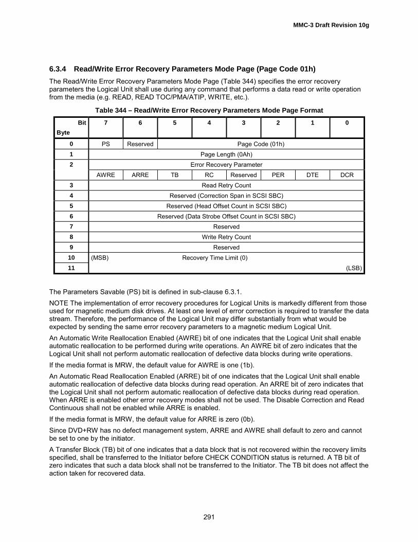
MMC-3 Draft Revision 10g
291
6.3.4 Read/Write Error Recovery Parameters Mode Page (Page Code 01h)The Read/Write Error Recovery Parameters Mode Page (Table 344) specifies the error recoveryparameters the Logical Unit shall use during any command that performs a data read or write operationfrom the media (e.g. READ, READ TOC/PMA/ATIP, WRITE, etc.).
Table 344 – Read/Write Error Recovery Parameters Mode Page Format
BitByte
7 6 5 4 3 2 1 0
0 PS Reserved Page Code (01h)1 Page Length (0Ah)2 Error Recovery Parameter
AWRE ARRE TB RC Reserved PER DTE DCR3 Read Retry Count4 Reserved (Correction Span in SCSI SBC)5 Reserved (Head Offset Count in SCSI SBC)6 Reserved (Data Strobe Offset Count in SCSI SBC)7 Reserved8 Write Retry Count9 Reserved
10 (MSB) Recovery Time Limit (0)11 (LSB)
The Parameters Savable (PS) bit is defined in sub-clause 6.3.1.NOTE The implementation of error recovery procedures for Logical Units is markedly different from thoseused for magnetic medium disk drives. At least one level of error correction is required to transfer the datastream. Therefore, the performance of the Logical Unit may differ substantially from what would beexpected by sending the same error recovery parameters to a magnetic medium Logical Unit.An Automatic Write Reallocation Enabled (AWRE) bit of one indicates that the Logical Unit shall enableautomatic reallocation to be performed during write operations. An AWRE bit of zero indicates that theLogical Unit shall not perform automatic reallocation of defective data blocks during write operations.If the media format is MRW, the default value for AWRE is one (1b).An Automatic Read Reallocation Enabled (ARRE) bit of one indicates that the Logical Unit shall enableautomatic reallocation of defective data blocks during read operation. An ARRE bit of zero indicates thatthe Logical Unit shall not perform automatic reallocation of defective data blocks during read operation.When ARRE is enabled other error recovery modes shall not be used. The Disable Correction and ReadContinuous shall not be enabled while ARRE is enabled.If the media format is MRW, the default value for ARRE is zero (0b).Since DVD+RW has no defect management system, ARRE and AWRE shall default to zero and cannotbe set to one by the initiator.A Transfer Block (TB) bit of one indicates that a data block that is not recovered within the recovery limitsspecified, shall be transferred to the Initiator before CHECK CONDITION status is returned. A TB bit ofzero indicates that such a data block shall not be transferred to the Initiator. The TB bit does not affect theaction taken for recovered data.

MMC-3 Draft Revision 10g
292
A Read Continuous (RC) bit of one indicates that the Logical Unit shall transfer the entire requestedlength of data without adding delays to perform error recovery procedures. This implies that the LogicalUnit may send data that is erroneous or fabricated in order to maintain a continuous flow of data. A RC bitof zero indicates that error recovery operations that cause delays are acceptable during the data transfer.A Post Error (PER) bit of one indicates that the Logical Unit shall report recovered errors. A PER bit ofzero indicates that the Logical Unit shall not report recovered errors. Error recovery procedures shall beperformed within the limits established by the error recovery parameters. This capability is different forDVD media. In order to enhance data recovery from DVD media, error correction shall always be used.Thus, PER shall not apply to error corrected data. This bit for DVD media shall only be used to reportwhen auto reallocation of a logical block has been performed. For CD media this capability is used onlyto report when the Layered Error correction has been used to recover the data.A Disable Transfer on Error (DTE) bit of one indicates that the Logical Unit shall terminate the datatransfer to the Initiator upon detection of a recovered error. A DTE bit of zero indicates that the LogicalUnit shall not terminate the data transfer upon detection of a recovered error.A Disable Correction (DCR) bit of one indicates that error correction codes shall not be used for data errorrecovery. A DCR bit of zero allows the use of error correction codes for data error recovery.An interpretation of the bits 5-0 in the Error Recovery Parameter byte for CD-ROM Logical Units is givenin Table 345. An interpretation of the bits 5-0 in the Error Recovery Parameter byte for DVD-ROM LogicalUnits is given in Table 346.The Read Retry Count field specifies the number of times that the controller shall attempt its readrecovery algorithm.The Write Retry Count field specifies the number of times that the controller shall attempt its writerecovery algorithm. This may not have any effect if the Logical Unit does not support read after writeoperations.A CIRC Recovered Data Error is defined as a block that the CIRC based error correction algorithm wasunsuccessful for a read attempt, but on a subsequent read operation no error was reported. The numberof subsequent read operations is limited to the read retry count. Layered error correction was not used.A CIRC Un-recovered Data Error is defined as a block that the CIRC based error correction algorithm wasunsuccessful on all read attempts up to the read retry count. Layered error correction was not used.An L-EC Recovered Data Error is defined as a block that the CIRC based error correction algorithm wasunsuccessful, but the layered error correction was able to correct the block within the read retry count.An L-EC Un-correctable Data Error is defined as a block that could not be corrected by layered errorcorrection within the read retry count.

MMC-3 Draft Revision 10g
293
Table 345 – CD-ROM Devices, error recovery description
Error code Description
00h The maximum error recovery procedures available are used. If an error occurs that is uncorrectablewith the error correction codes (ECC) on the media, data transfer is terminated with CHECKCONDITION status. The block with the error is not transferred. The sense key is set to MEDIUMERROR. The information bytes give the address of the block where the un-recovered error wasdetected. Recovered errors are not reported.
01h Only retries of the read operation and CIRC are used (layered error correction is not used). OnlyCIRC un-recovered data errors are reported. If an CIRC un-recovered data error occurs, datatransfer is terminated with CHECK CONDITION status. The block with the error is not transferred.The sense key is set to MEDIUM ERROR. The information bytes give the address of the block wherethe un-recovered error was detected. Recovered errors are not reported.
04h The maximum error recovery procedures available are used. Recovered data errors are reported. If arecovered data error occurs, data transfer is not terminated. However, when the data transfer hascompleted CHECK CONDITION status is reported. The sense key is set to RECOVERED ERROR.The information bytes give the address of the last block where a recovered data error was detected.If a data error occurs that is uncorrectable with the ECC information available on the media, datatransfer is terminated and CHECK CONDITION status is reported. The block with the error is nottransferred. The sense key is set to MEDIUM ERROR. The information bytes give the address of theblock where the uncorrectable error was detected.
05h Only retries of the read operation and CIRC are used (layered error correction is not used).Recovered data errors are reported. If a recovered data error occurs, data transfer is not terminated.However, when the data transfer has completed CHECK CONDITION status is reported. The sensekey is set to RECOVERED ERROR. The information bytes give the address of the last block where aCIRC recovered data error was detected.If an un-recovered data error occurs, data transfer is terminated and CHECK CONDITION status isreported. The block with the error is not transferred. The sense key is set to MEDIUM ERROR. Theinformation bytes give the address of the block where the un-recovered error was detected.
06h The maximum error recovery procedures are used. Recovered data errors are reported. If arecovered data error occurs data transfer is terminated and CHECK CONDITION status is reported.The block with the recovered error is not transferred. The sense key is set to RECOVERED ERROR.The information bytes give the address of the block where the recovered data error was detected.If a data error occurs that is uncorrectable with the ECC information on the medium, data transfer isterminated with CHECK CONDITION status. The block with the error is not transferred. The sensekey is set to MEDIUM ERROR. The information bytes give the address of the block where theuncorrectable error was detected.
07h Only retries of the read operation are used (layered error correction is not used). CIRC recovereddata errors are reported. If a CIRC recovered data error occurs, data transfer is terminated withCHECK CONDITION status. The block with the recovered error is not transferred. The sense key isset to RECOVERED ERROR. The information bytes give the address of the block where therecovered data error was detected.If an CIRC un-recovered data error occurs, data transfer is terminated with CHECK CONDITIONstatus. The block with the error is not transferred. The sense key is set to MEDIUM ERROR. Theinformation bytes give the address of the block where the uncorrectable error was detected.
10h If data transfer can be maintained, the maximum error recovery procedures available are used.(RC=1.) If an error occurs that is uncorrectable with the error codes (ECC) on the media, or isuncorrectable in time to maintain data transfer, the data transfer is not terminated. However, whenthe data transfer has completed, CHECK CONDITION status is reported. The sense key is set toMEDIUM ERROR. The information bytes give the address of the block where the first un-recoverederror was detected. Recovered errors are not reported.

MMC-3 Draft Revision 10g
294
Table 345 – CD-ROM Devices, error recovery description (cont.)
Error Code Description
11h If data transfer can be maintained, retries of the read operation and CIRC are used (layered errorcorrection is not used). (RC=1.) Only CIRC un-recovered data errors are reported. If a CIRC un-recovered data error occurs, data transfer is not terminated. However, when data transfer hascompleted, CHECK CONDITION status is reported. The sense key is set to MEDIUM ERROR. Theinformation bytes give the address of the block where the first un-recovered error was detected.Recovered errors are not reported.If a data error occurs that is uncorrectable with the ECC information available on the media, datatransfer is terminated and CHECK CONDITION status is reported. The block with the error is nottransferred. The sense key is set to MEDIUM ERROR. The information bytes give the address of theblock where the uncorrectable error was detected.
14h If data transfer can be maintained, the maximum error recovery procedures available are used.(RC=1.) Recovered data errors are reported. If a recovered data error occurs, data transfer is notterminated. However, when the data transfer has completed, CHECK CONDITION status is reported.The sense key is set to RECOVERED ERROR. The information bytes give the address of the blockwhere a recovered data error was detected.If an data error occurs that is uncorrectable with the ECC information available on the media, or isuncorrectable in time to maintain data transfer, the data transfer is not terminated. However, whenthe data transfer has completed, CHECK CONDITION status is reported. The sense key is set toMEDIUM ERROR. The information bytes give the address of the block where the first un-recoverederror was detected. Reporting un-recovered errors takes precedence over reporting recovered errors.
15h If data transfer can be maintained, retries of the read operation and CIRC are used (layered errorcorrection is not used). (RC=1.) Recovered data errors are reported. If a recovered data error occurs,data transfer is not terminated. However, when the data transfer has completed CHECK CONDITIONstatus is reported. The sense key is set to RECOVERED ERROR. The information bytes give theaddress of the block where a CIRC recovered data error was detected.If an un-recovered data error occurs, data transfer is not terminated. However, when the datatransfer has completed CHECK CONDITION status is reported. The sense key is set to MEDIUMERROR. The information bytes give the address of the block where the un-recovered error wasdetected. Recovered errors are not reported.
20h The maximum error recovery procedures available are used. If an error occurs that is uncorrectablewith the error correction codes (ECC) on the media, data transfer is terminated with CHECKCONDITION status. The block with the error is transferred. The sense key is set to MEDIUMERROR. The information bytes give the address of the block where the un-recovered error wasdetected. Recovered errors are not reported.
21h Only retries of the read operation and CIRC are used (layered error correction is not used). OnlyCIRC un-recovered data errors are reported. If an CIRC un-recovered data error occurs, datatransfer is terminated with CHECK CONDITION status. The block with the error is transferred. Thesense key is set to MEDIUM ERROR. The information bytes give the address of the block where theun-recovered error was detected. Recovered errors are not reported.
24h The maximum error recovery procedures available are used. Recovered data errors are reported. If arecovered data error occurs, data transfer is not terminated. However, when the data transfer hascompleted, CHECK CONDITION status is reported. The sense key is set to RECOVERED ERROR.The information bytes give the address of the last block where a recovered data error was detected.If a data error occurs that is uncorrectable with the ECC information available on the media, datatransfer is terminated and CHECK CONDITION status is reported. The block with the error istransferred. The sense key is set to MEDIUM ERROR. The information bytes give the address of theblock where the uncorrectable error was detected.

MMC-3 Draft Revision 10g
295
Table 345 – CD-ROM Devices, error recovery description (cont.)
Error Code Description
25h Only retries of the read operation and CIRC are used (layered error correction is not used).Recovered data errors are reported. If a recovered data error occurs, data transfer is not terminated.However, when the data transfer has completed CHECK CONDITION status is reported. The sensekey is set to RECOVERED ERROR. The information bytes give the address of the last block where aCIRC recovered data error was detected.If an un-recovered data error occurs, data transfer is terminated and CHECK CONDITION status isreported. The block with the error is transferred. The sense key is set to MEDIUM ERROR. Theinformation bytes give the address of the block where the un-recovered error was detected.
26h The maximum error recovery procedures are used. Recovered data errors are reported. If arecovered data error occurs data transfer is terminated and CHECK CONDITION status is reported.The block with the recovered error is transferred. The sense key is set to RECOVERED ERROR.The information bytes give the address of the block where the recovered data error was detected.If a data error occurs that is uncorrectable with the ECC information on the medium, data transfer isterminated with CHECK CONDITION status. The block with the error is transferred. The sense key isset to MEDIUM ERROR. The information bytes give the address of the block where theuncorrectable error was detected.
27h Only retries of the read operation are used (layer error correction is not used). CIRC recovered dataerrors are reported. If a CIRC recovered data error occurs, data transfer is terminated with CHECKCONDITION status. The block with the recovered error is transferred. The sense key is set toRECOVERED ERROR. The information bytes give the address of the block where the recovereddata error was detected.If a CIRC un-recovered data error occurs, data transfer is terminated with CHECK CONDITIONstatus. The block with the error is transferred. The sense key is set to MEDIUM ERROR. Theinformation bytes give the address of the block where the un-recovered error was detected.
30h Same as code 10h31h Same as code 11h34h Same as code 14h35h Same as code 15h

MMC-3 Draft Revision 10g
296
Table 346 – DVD Devices, Error Recovery Description
Code Error Recovery Description
00h The maximum error recovery procedures available are used. If an error occurs which isuncorrectable with the error correction codes (ECC) on the media, data transfer is terminated withCHECK CONDITION status. The block with the error is not transferred. The sense key is set toMEDIUM ERROR. The information bytes give the address of the block where the un-recoverederror was detected. Recovered errors are not reported.
04h The maximum error recovery procedures available are used. Recovered data errors are reported. Ifa recovered data error occurs, data transfer is not terminated. However, when the data transfer hascompleted CHECK CONDITION status is reported. The sense key is set to RECOVERED ERROR.The information bytes give the address of the last block where a recovered data error wasdetected. If a data error occurs that is uncorrectable with the ECC information available on themedia, data transfer is terminated and CHECK CONDITION status is reported. The block with theerror is not transferred. The sense key is set to MEDIUM ERROR. The information bytes give theaddress of the block where the uncorrectable error was detected. The only possible recoverederrors are when a block is automatically reassigned using ARRE.
10h If data transfer can be maintained, the maximum error recovery procedures available are used. (RC= 1.) If an error occurs which is uncorrectable with the error correction codes (ECC) on the media,or is uncorrectable in time to maintain data transfer, the data transfer is not terminated. However,when the data transfer has completed, CHECK CONDITION status is reported. The sense key isset to MEDIUM ERROR. The information bytes give the address of the block where the firstunrecovered error was detected. Recovered errors are not reported.
20h The maximum error recovery procedures available are used. If an error occurs that is uncorrectablewith the error correction codes (ECC) on the media, data transfer is terminated with CHECKCONDITION status. The block with the error is transferred. The sense key is set to MEDIUMERROR. The information bytes give the address of the block where the un-recovered error wasdetected. Recovered errors are not reported.
24h The maximum error recovery procedures available are used. Recovered data errors are reported. Ifa recovered data error occurs data transfer is not terminated. However, when the data transfer hascompleted, CHECK CONDITION status is reported. The sense key is set to RECOVEREDERROR. The information bytes give the address of the last block where a recovered data error wasdetected. If a data error occurs that is uncorrectable with the ECC information available on themedia data transfer is terminated and CHECK CONDITION status is reported. The block with theerror is transferred. The sense key is set to MEDIUM ERROR. The information bytes give theaddress of the block where the uncorrectable error was detected. The only possible recoverederrors are when a block is automatically reassigned using ARRE.
The Read Retry Count field specifies the number of times that the Logical Unit shall attempt its readrecovery algorithm.The Correction Span field should be set to zero.The Head Offset Count field should be set to zero.The Data Strobe Offset Count field should be set to zero.The Write Retry Count field specifies the number of times that the Logical Unit shall attempt its writerecovery algorithm. This may not have any effect if the Logical Unit does not support read after writeoperations.The Recovery Time Limit field should be set to zero.A CIRC Recovered Data Error is defined as a block for which the CIRC based error correction algorithmwas unsuccessful for a read attempt, but on a subsequent read operation no error was reported. Thenumber of subsequent read operations is limited to the read retry count. Layered error correction was notused.

MMC-3 Draft Revision 10g
297
A CIRC Un-recovered Data Error is defined as a block for which the CIRC based error correctionalgorithm was unsuccessful on all read attempts up to the read retry count. Layered error correction wasnot used.An L-EC Recovered Data Error is defined as a block for which the CIRC based error correction algorithmwas unsuccessful, but the layered error correction was able to correct the block within the read retrycount.

MMC-3 Draft Revision 10g
298
6.3.5 Write Parameters Page (Page Code 05h)The Write Parameters Page (Table 347) provides parameters that are often needed in the execution ofcommands that write to the media.The values in this page do not necessarily reflect the status on a given medium. They may be used, asapplicable, when a write operation occurs. If any parameter value is incompatible with the currentmedium, the Logical Unit shall terminate any write type command with CHECK CONDITION status andset SK/ASC/ASCQ values to ILLEGAL REQUEST/ILLEGAL MODE FOR THIS TRACK. Fields notrequired or ignored for the current medium may contain 0 for the default mode parameter value.Fields and bits within the Write Parameters Page not utilized by the installed medium may be ignored.For DVD-RW media, if a medium is in Sequential recording mode, usage of this mode page shall conformto descriptions for DVD-R unless otherwise specified. If a medium is in Restricted overwrite mode, thismode page shall not be used.When a MRW disc is mounted and recognized by the Logical Unit, it shall set write speed and internalwrite parameters as needed to properly access the medium. This shall be done without initiatorintervention. Furthermore, the Logical Unit shall not modify the current parameters of the WriteParameters Page. If the initiator changes the Write Parameters Page, MRW disc operation shall not beaffected.When a disc is mounted which does not have the MRW format and a FORMAT UNIT command is sent forthe purpose of formatting the disc as MRW, the same rule applies. Specifically, the initiator is notrequired to set the Write Parameters Page prior to sending the FORMAT UNIT command when specifyingformat type 24h. Furthermore, the Logical Unit shall not alter current the Write Parameters Page inperforming the format.

MMC-3 Draft Revision 10g
299
Table 347 – Write Parameters Page
BitByte
7 6 5 4 3 2 1 0
0 PS Reserved Page Code (05h)1 Page Length (32h)2 Reserved BUFE LS_V Test Write Write Type3 Multi-session FP Copy Track Mode4 Reserved Data Block Type5 Link Size6 Reserved7 Reserved Initiator Application Code8 Session Format9 Reserved
10 (MSB)11 Packet Size1213 (LSB)14 (MSB) Audio Pause Length15 (LSB)16 (MSB)17 ...... Media Catalog Number30 ...31 (LSB)32 (MSB)33 ...... International Standard Recording Code46 ...47 (LSB)48 Sub-header Byte 049 Sub-header Byte 1
50 Sub-header Byte 251 Sub-header Byte 3
52 - 55 Vendor Specific
The Parameter Savable bit is defined in sub-clause 6.3.1.The BUFE bit, when set to one, indicates that Buffer Under-run Free recording is enabled for sequentialrecording. The Logical Unit shall perform loss less-linking and continue the writing when the bufferbecomes empty. When set to zero, it shall indicate that Logical Unit shall terminate writing and performlinking. In order to minimize compatibility problems, the default value for BUFE should be zero for CD-R/RW Logical Units.

MMC-3 Draft Revision 10g
300
The LS_V (Link Size Valid) bit, when set to one indicates that the value in the Link Size field is valid.When set to zero, indicates compatibility with legacy Logical Units that did not implement the Link Sizefield; such Logical Units assume a Link Size of 7.The Link Size field specifies the Linking Loss area size in sectors. The Link Size field is valid only forWrite Type �Packet/Incremental.� When another Write Type is specified, device shall ignore LS_V bit andLink Size field. The Logical Unit shall accept values that are valid for the Logical Unit but not valid for thecurrent medium. If writing is attempted when an invalid Link Size is set, the Logical Unit shall generateCHECK CONDITION status and set SK/ASC/ASCQ values to ILLEGAL REQUEST/ILLEGAL MODE FORTHIS TRACK.On CD-R/RW media the Test Write bit is valid only for Write Type 1 or 2 (Track at Once or Session atOnce). On DDCD-R/RW media the Test Write bit is valid only for Write Type 1 or 2 (Track at Once orSession at Once). On DVD-R media, the Test Write bit is valid only for Write Type 0 or 2 (Incremental orDisc-at-once). When the Test Write bit is set to one, it indicates that the device performs the writeprocess, but does not write data to the media. When the bit is set to zero the Write laser power is setsuch that user data is transferred to the media. In addition, all track and disc information collected, duringtest write mode, shall be cleared. It should be noted that the number of tracks reserved or written may belimited in test write mode.Write Type Field (Table 348) specifies the stream type to be used during writing. Write Type values areshown in Table 348.
Table 348 – Write Type Field
Value Definition
00h Packet/Incremental01h Track-at-once02h Session-at-once03h Raw
04h - 0Fh Reserved
Packet/Incremental - the device shall perform packet/Incremental writing when WRITE commands areissued.Track At Once - the device shall perform Track At Once recording when write commands are issued.Session At Once - the device shall perform Session At Once recording. For CD, this mode requires that acue sheet be sent prior to sending write commands.Raw - the device shall write data as received from the Initiator. In this mode, the Initiator sends the Lead-in. The Initiator shall provide Q Sub-channel in this mode, the only valid Data Block Types are 1, 2, and3. The Next Writable Address starts at the beginning of the Lead-in (this shall be a negative LBA on ablank disc).NOTE: In RAW record mode the Logical Unit shall not generate run-in and run-out blocks (main and Sub-channel 1 data) but shall generate and record the link block. Write Type of Track-at-once and Raw areinvalid when DVD-R media is present.

MMC-3 Draft Revision 10g
301
The Multi-session field defines how session closure affects the opening of the next session. See Table349.
Table 349 – Multi-session Field Definition
Multi-sessionField
Action Upon Session Closure
00b No B0 pointer. Next Session not allowed01b For the CD media, B0 pointer = FF:FF:FF. Next session not allowed.
For the DDCD media, B0 pointer = F:FF:FF:FF. Field reserved fornon-CD media
10b Reserved11b Next session allowed. B0 pointer = next possible program area.
The FP bit, when set to one indicates that the packet type is fixed. Otherwise, the packet type is variable.This bit is ignored unless the write type is set to 0 (Packet). For DVD-R, this bit shall default to one.A Copy bit with value one indicates that this is the first or higher generation copy of a copyright protectedtrack. When set to one, the copyright bit in the control nibble of each mode 1 Q Sub-channel shallalternate between 1 and 0 at 9.375 Hz. The duty cycle is 50%, changing every 4 blocks. The initial valueon the medium is zero.For DDCD, this bit shall be set to zero.Track Mode is the Control nibble in all Mode 1 Q Sub-channel in the track. The default value of this fieldfor DVD-R Logical Units shall be 5. The default value of this field for DDCD-R/RW Logical Units shall be5.Data Block Type defines both the specific data fields in a user data block and its size. The Data BlockType codes are defined in Table 350. This size is used for writing instead of the block size set in themode select header. The default value of this field for DVD-R Logical Units shall be 8. The default valueof this field for DDCD-R/WR Logical Units shall be 8.

MMC-3 Draft Revision 10g
302
Table 350 – Data Block Type Codes
Value BlockSize
Definition Requirement
0 2 352 Raw data 2 352 bytes of raw data (not valid for write type = packet) Optional1 2 368 Raw data with P and Q Sub-channel
2 352 bytes of raw data,16 bytes for P & Q Sub-channel (see Table 152):Bytes 0..9 are Q Sub-channel dataBytes 10..11 are Q Sub-channel EDCBytes 12..14 are zeroByte 15, most significant bit has state of P Sub-channel bit(not valid for write type = packet)
Optional
2 2 448 Raw data with P-W Sub-channel appended:2 352 bytes of raw data.96 bytes of pack form R-W Sub-channel in the low order 6 bits of each byte.Bit 7 of each byte contains the P Sub-channel state and bit 6 of each bytecontains the Q Sub-channel bit. (not valid for write type = packet)
Optional
3 2 448 Raw data with raw P-W Sub-channel appended:2 352 bytes of raw data.96 bytes of raw P-W Sub-channel. (not valid for write type = packet)
Optional
4 - 6 Reserved values7 NA Vendor Specific Optional8 2 048 Mode 1 (ISO/IEC 10149):
2 048 bytes of user dataMandatory
9 2 336 Mode 2 (ISO/IEC 10149): 2 336 bytes of user data. Optional10 2 048 Mode 2 (CD-ROM XA, form 1):
2 048 bytes of user data, sub-header from write parameters.Mandatory
11 2 056 Mode 2 (CD-ROM XA, form 1):8 bytes of sub-header, 2 048 bytes of user data
Optional
12 2 324 Mode 2 (CD-ROM XA, form 2):2 324 bytes of user data. Sub-header is taken from write parameters.
Optional
13 2 332 Mode 2 (CD-ROM XA, form 1, form 2, or mixed form):8 bytes of sub-header2 324 bytes of user data
Mandatory
14 - Reserved values15 NA Vendor Specific Optional
Notes:1. When a track has been designated for packet writing, the device shall ensure that the TDB is written upon
receipt of the write command.2. With the exceptions of data block types 1, 2, and 3, the device shall generate all P Sub-channel and all mode
1, mode 2, and mode 3 Q Sub-channel.3. For data block types 8 through 13, the device shall generate all sync fields and all headers.4. For data blocks of mode 1 or of mode 2, form 1, the device shall generate EDC and L-EC parity.5. For data block types 0, 1, 2, and 3, the device shall perform no data scrambling per ISO/IEC 10149.6. For data block types 8 through 13, the device shall perform data scrambling per ISO/IEC 10149.7. Only Type 10 is valid for DDCD media.

MMC-3 Draft Revision 10g
303
The Initiator Application Code field typically has the value zero. When the unrestricted Use Disc bit in theDisc Information Block (Table 162) is set to one, the Initiator Application Code field shall be ignored bythe device. If the Unrestricted Use Disc bit is zero, then the Initiator Application Code shall be set to theappropriate value for the medium in order that writing be allowed. An Initiator Application Code of zero isused for a Restricted Use - General Purpose Disc.The Session Format code is to be written in the TOC of the session containing this track. The SessionFormat code is the PSEC byte of the mode 1, point A0 TOC entry. For DDCD media, this is always set to20h.
Table 351 – Session Format Codes
SessionFormat Codes
Session Format
00h CD-DA, or CD-ROM or other data discs10h CD-I Disc20h CD-ROM XA Disc, DDCD Disc
All OtherValues
Reserved
The Packet Size field, if FP bit is set to one, specifies the number of User Data Blocks per fixed packet.The Packet Size field, if FP bit is set to 0, shall be ignored. For DVD-R media, the default Packet Sizeshall be 16. Audio Pause Length is the number of blocks from the beginning of the track that the mode 1Q Sub-channel INDEX shall be zero. If this number is zero, then there is no period where the Mode 1 QSub-channel INDEX shall be zero. The default value shall be 150. This field is valid only for audio tracks,otherwise it is ignored.The Media Catalog Number (MCN) shall be written in the mode 2 Q Sub-channel in at least one out ofevery 100 blocks in the program area. The Initiator may include bytes 14 & 15, however, the Logical Unitshall ignore these bytes and insert the appropriate Zero and AFRAME values. When the MCN is returnedto the Initiator the Media Catalog Number (MCN) is formatted as in Table 225.The International Standard Recording Code (ISRC) is formatted as in Table 227.For the DDCD, this field is ignored.

MMC-3 Draft Revision 10g
304
6.3.6 CD device parameters Page (Page Code 0Dh)The CD Parameters page (Table 352) specifies parameters that affect all CD-ROM data types.
Table 352 – CD Parameters page
BitByte
7 6 5 4 3 2 1 0
0 PS Reserved Page Code (0Dh)1 Parameter Length (06h)2 Reserved3 Reserved Inactivity Timer Multiplier4 (MSB) Number Of MSF - S Units Per MSF - M Unit5 (LSB)6 (MSB) Number Of MSF - F Units Per MSF - S Unit7 (LSB)
The Parameter Savable bit is defined in sub-clause 6.3.1.The inactivity timer multiplier value specifies the length of time that the Logical Unit shall remain in thehold track state after completion of a seek or read operation (Table 353).
Table 353 – Inactivity timer multiplier values
Inactivity timermultiplier value
minimum time inhold track state
Inactivity timermultiplier value
Minimum time inhold track state
0 Vendor-specific 8 16 s1 125 ms 9 32 s2 250 ms Ah 1 min.3 500 ms Bh 2 min.4 1 s Ch 4 min.5 2 s Dh 8 min.6 4 s Eh 16 min.7 8 s Fh 32 min.
The number of S units per M unit field gives the ratio of these MSF address values. For media conformingto the CD data and CD-DA standard, this value is 60.The number of F units per S unit field gives the ratio of these MSF address values. For media conformingto the CD data and CD-DA standard, this value is 75.

MMC-3 Draft Revision 10g
305
6.3.7 CD Audio Control Page (Page Code 0Eh)The CD Audio Control Page (Table 354) sets the playback modes and output controls for subsequentPLAY AUDIO commands and any current audio playback operation.
Table 354 – CD Audio Control Page Format
BitByte
7 6 5 4 3 2 1 0
0 PS Reserved Page Code (0Eh)1 Page Length (0Eh)2 Reserved IMMED
= 1SOTC
Default =0
Reserved
3 Reserved4 Reserved5 Reserved6 Obsolete (75)7 Obsolete (75)8 Reserved CDDA Output Port 0 Channel Selection9 Output Port 0 Volume Default FFh
10 Reserved CDDA Output Port 1 Channel Selection11 Output Port 1 Volume Default FFh12 Reserved CDDA Output Port 2 Channel Selection13 Output Port 2 Volume Default 00h14 Reserved CDDA Output Port 3 Channel Selection15 Output Port 3 Volume Default 00h
The Parameter Savable bit is defined in sub-clause 6.3.1.The Immediate Bit (IMMED) is used for information purposes only; audio play commands shall sendcompletion status as soon as the playback operation has been started. This bit shall always be set to 1.A Stop On Track Crossing (SOTC) bit of zero indicates the Logical Unit shall terminate the audio playbackoperation when the transfer length is satisfied. Multiple tracks shall be played as necessary. Periods oftime encoded as audio pause/silence at the beginning of tracks, (index 0) shall also be played. A SOTCbit of one indicates the Logical Unit shall terminate the audio playback operation when the beginning of afollowing track is encountered. The SOTC bit is mandatory.The CDDA Output Port Channel Selection field (Table 355) specifies the Red Book audio channels that aspecific output port shall be connected. More than one output port may be connected to an audiochannel. More than one audio channel may be connected to an output port.

MMC-3 Draft Revision 10g
306
Table 355 – CDDA Output Port Channel Selection Codes
Code Description
0000b Output port muted0001 Connect audio channel 0 to this output port
0010b Connect audio channel 1 to this output port0011b Connect audio channel 0 and audio channel 1 to this output port0100b Connect audio channel 2 to this output port1000b Connect audio channel 3 to this output port
The Output Port Volume Control indicates the relative volume level for this audio output port. The valueused is specified as an attenuation of the normal volume level. A value of zero indicates the minimumvolume level (Mute), and a value of FFh indicates maximum volume (No attenuation) level. It isrecommended that the MUTE and volume functions should be supported on a per channel basis. Theattenuation used shall be as specified in Table 356. All values not shown in the table shall be valid, withthe attenuation selected by interpolating using the known table values.It is recommended that the Logical Unit support at least 16 volume levels. The actual attenuation levelsfor any given Binary attenuation value shall be given by the following equation: 20 Log ((Binary Level +1)/256)Note: Audio channel volume control regarding channel selection of MUTE vs. Volume Level setting of 0. Itis recommend that Logical Units allow the setting of the Channel Selection fields to MUTE and also allowthe setting of the Volume Level field to 0. It is up to the Logical Unit to determine how to shut off thevolume, either via muting circuitry or via the volume control.
Table 356 – Attenuation Levels for Audio
Binary Level Attenuation
FFh 0db (0n)F0h -0.52E0h -1.12C0h -2.4580h -5.9540h -11.920h -17.810h -23.60Fh -24.10Eh -24.60Ch -25.908h -29.104h -34.202h -38.601h -42.100h Mute (Off)
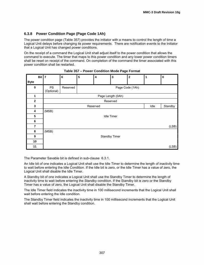
MMC-3 Draft Revision 10g
307
6.3.8 Power Condition Page (Page Code 1Ah)The power condition page (Table 357) provides the initiator with a means to control the length of time aLogical Unit delays before changing its power requirements. There are notification events to the Initiatorthat a Logical Unit has changed power conditions.On the receipt of a command the Logical Unit shall adjust itself to the power condition that allows thecommand to execute. The timer that maps to this power condition and any lower power condition timersshall be reset on receipt of the command. On completion of the command the timer associated with thispower condition shall be restarted.
Table 357 – Power Condition Mode Page Format
BitByte
7 6 5 4 3 2 1 0
0 PS(Optional)
Reserved Page Code (1Ah)
1 Page Length (0Ah)2 Reserved3 Reserved Idle Standby4 (MSB)5 Idle Timer67 (LSB)8 (MSB)9 Standby Timer
1011 (LSB)
The Parameter Savable bit is defined in sub-clause 6.3.1.An Idle bit of one indicates a Logical Unit shall use the Idle Timer to determine the length of inactivity timeto wait before entering the Idle Condition. If the Idle bit is zero, or the Idle Timer has a value of zero, theLogical Unit shall disable the Idle Timer.A Standby bit of one indicates a Logical Unit shall use the Standby Timer to determine the length ofinactivity time to wait before entering the Standby condition. If the Standby bit is zero or the StandbyTimer has a value of zero, the Logical Unit shall disable the Standby Timer.The Idle Timer field indicates the inactivity time in 100 millisecond increments that the Logical Unit shallwait before entering the Idle condition.The Standby Timer field indicates the inactivity time in 100 millisecond increments that the Logical Unitshall wait before entering the Standby condition.

MMC-3 Draft Revision 10g
308
6.3.9 Fault / Failure Reporting Control Page (Page Code 1Ch)The Fault / Failure Reporting Control page (Table 358) defines the methods used by the target to controlthe reporting and the operations of specific informational exception conditions. This page shall only applyto informational exceptions when CHECK CONDITION status is reported and ASC set to FAILUREPREDICTION THRESHOLD EXCEEDED to the Initiator.Informational exception conditions occur as a result of vendor specific events within a target. Aninformational exception condition may occur asynchronous to any commands issued by an applicationclient.
Table 358 – Fault/ Failure Reporting Control Page
BitByte
7 6 5 4 3 2 1 0
0 PS Reserved Page Code (1Ch)1 Page Length (0Ah)2 Perf Reserved DExcept Test Reserved LogErr (0)3 Reserved MRIE4 (MSB)5 Interval Timer67 (LSB)8 (MSB)9 Report Count
1011 (LSB)
The Parameter Savable bit is defined in sub-clause 6.3.1.A Performance bit (Perf) of zero indicates that informational exception operations that are the cause ofdelays are acceptable. A Perf bit of one indicates the Logical Unit shall not cause delays while doinginformational exception operations. A Perf bit set to one may cause the Logical Unit to disable some or allof the informational exception operations, thereby limiting the reporting of informational exceptionconditions.A disable exception control (DExcpt) bit of zero indicates information exception operations shall beenabled. The reporting of informational exception conditions when the DExcpt bit is set to zero isdetermined from the MRIE field. A DExcpt bit of one indicates the Logical Unit shall disable all informationexception operations. The MRIE field is ignored when DExcpt is set to one.A Test bit of one shall create a false Logical Unit failure at the next interval time (as specified by theInterval timer field), if the DExcpt bit is not set. When the Test bit is one, the MRIE and Report count fieldsshall apply as if the Test bit were zero. The false Logical Unit failure shall be reported with an ASC ofFAILURE PREDICTION THRESHOLD EXCEEDED (FALSE). If both the Test and the DExcpt bits areone, the Logical Unit shall terminate the MODE SELECT command with CHECK CONDITION status andset SK/ASC/ASCQ values to ILLEGAL REQUEST/INVALID FIELD IN PARAMETER LIST. A Test bit ofzero shall instruct the Logical Unit not to generate any false Logical Unit failure notifications.The log errors bit (LogErr) of zero indicates that the logging of informational exception conditions within aLogical Unit is vendor specific.

MMC-3 Draft Revision 10g
309
The Method of Reporting Informational Exceptions field (MRIE) (see Table 359) indicates the methodsthat shall be used by the Logical Unit to report informational exception conditions. The priority ofreporting multiple information exceptions is vendor specific.
Table 359 – Method of Reporting Informational Exceptions Field
MRIE Description
0h No reporting of informational exception condition:This method instructs the target to not report information exception conditions.
1h - 3h Reserved4h Unconditionally generate recovered error:
This method instructs the target to report informational exception conditions, regardlessof the value of the Per bit of the error recovery parameters mode page, by returning aCHECK CONDITION status on any command. SK shall be set to RECOVERED ERRORand the ASC shall be set to FAILURE PREDICTION THRESHOLD - Predicted LogicalUnit Failure or FAILURE PREDICTION THRESHOLD EXCEEDED - Predicted MediaFailure.The command that has the CHECK CONDITION shall complete without error before anyinformational exception condition may be reported.
5h - Bh ReservedCh - Fh Vendor specific
The Interval Timer field indicates the period in 100 millisecond increments that a informational exceptioncondition has occurred. The Logical Unit shall not report informational exception conditions morefrequently than the time specified by the Interval Timer field and as soon as possible after the timerinterval has elapsed. After the informational exception condition has been reported, the interval timer shallbe restarted. A value of zero or FFFFFFFFh in the Interval Timer field shall indicate the timer interval isvendor specific.The Report Count field indicates the number of times to report an informational exception condition to theapplication client. A value of zero in the Report Count field indicates there is no limit to the number oftimes the Logical Unit shall report an informational exception condition. The default value of this field shallbe zero.The maintaining of the Interval Timer and the Report Count field across power cycles and/or resets by theLogical Unit shall be vendor specific.

MMC-3 Draft Revision 10g
310
6.3.10 Time-out and Protect Page (Page Code 1Dh)The Time-out and Protect page (Table 360) specifies parameters that affect Logical Unit operation.
Table 360 – Time-out & Protect Page
BitByte
7 6 5 4 3 2 1 0
0 PS Reserved Page Code (1Dh)1 Page Length (08h)2 Reserved3 Reserved4 Reserved TMOE
Default 0DISP
Default 0SWPP
Default 05 Reserved6 (MSB) Group 1 Minimum Time-out (Seconds)7 (LSB)8 (MSB) Group 2 Minimum Time-out (Seconds)9 (LSB)
The Parameter Savable bit is defined in sub-clause 6.3.1.The Time Out Enable bit (TMOE), when set to one, indicates the time out parameters are in effect. Whenset to zero, indicates the command shall not time out.The DISP bit when set to 1 shall make the Logical Unit unavailable until power has been removed andthen reapplied. The Logical Unit shall report not ready for all media access after this bit has been set to 1.The SWPP bit provides a Software Write Protect until power has been removed and then reapplied.When this bit is set to 1 the Logical Unit shall prevent writes to the media. When the bit is set to 1, theLogical Unit shall flush any data in the Cache to the media before preventing any further writes.See the Time-out model for more information on the Group 1 & 2 Minimum Time-out fields.

MMC-3 Draft Revision 10g
311
6.3.11 CD/DVD Capabilities and Mechanical Status Page (Page Code 2Ah)The CD/DVD Capabilities and Mechanical Status Page (Table 361) is read only and shall not be set withMode Select.
Table 361 – CD/DVD Capabilities and Mechanical Status PageBit
Byte7 6 5 4 3 2 1 0
0 PS Reserved Page Code (2Ah)
1 Page Length (28+4*(maximum number of n))
2 Reserved DVD- RAMRead
DVD-R Read DVD-ROMRead
Method 2 CD-RW Read CD-R Read
3 Reserved DVD- RAMWrite
DVD-R Write Reserved Test Write CD-R/RWWrite
CD-R Write
4 BUF Multi Session Mode 2 Form2
Mode 2 Form1
Digital Port(2)
Digital Port(1)
Composite Audio Play
5 Read BarCode
UPC ISRC C2 Pointerssupported
R-W De-interleaved &
corrected
R-WSupported
CD-DAStream isAccurate
CD-DA CmdsSupported
6 Loading Mechanism Type Reserved Eject(Individual orMagazine)
PreventJumper
LockState
Lock
7 Reserved R-W inLead-In
Side ChangeCapable
S/W SlotSelection
(SSS)
ChangerSupports
Disc Present
SeparateChannel
Mute
Separatevolume levels
8 (MSB) Obsolete
9 (LSB)
10 (MSB) Number of Volume Levels Supported
11 (LSB)
12 (MSB) Buffer Size Supported
13 (LSB)
14 (MSB) Obsolete
15 (LSB)
16 Reserved
17 Reserved Length LSBF RCK BCKF Reserved
18 - 21 Obsolete
22 (MSB) Copy Management Revision Supported
23 (LSB)24 - 26 Reserved
27 Reserved Rotation Control Selected28 (MSB) Current Write Speed Selected29 (LSB)30 (MSB) Number of Logical Unit Write Speed Performance Descriptor Tables (n)31 (LSB)
32 - 35 Logical Unit Write Speed Performance Descriptor Block #136 - 39 Logical Unit Write Speed Performance Descriptor Block #2
: :n*4+28 ~ n*4+31
Logical Unit Write Speed Performance Descriptor Block #n
Padding

MMC-3 Draft Revision 10g
312
The Parameter Savable bit is defined in sub-clause 6.3.1.The Page Length field shall be set to a maximum length that contains the maximum number of LogicalUnit Write Speed Performance Descriptor Blocks. The Page Length is fixed for a Logical Unit, but may bedifferent from one Logical Unit to another. If the Logical Unit Write Speed Performance Descriptor Blockfor mounted media is shorter than the maximum length of the Logical Unit Write Speed PerformanceDescriptor Block, then the rest of the field shall be padded with zeros. If a Logical Unit does not supporthigh speed CD-R/RW recording, the Logical Unit shall not return mode page data after byte 26.When DVD-RAM Read is set to one, the Logical Unit shall support reading DVD-RAM media.When DVD-R Read is set to one, the Logical Unit shall support reading DVD-R media.When DVD-ROM Read bit is set to one, the Logical Unit shall support reading DVD-ROM media.When Method 2 is set to one, the Logical Unit shall support the reading fixed packet tracks on CD-R/RWmedia where the Addressing type is Method 2.When CD-RW Read is set to one, the Logical Unit shall support reading CD-RW media.When CD-R Read is set to one, the Logical Unit shall support the read function of CD-R disc.When DVD-RAM Write is set to one, the Logical Unit shall support writing DVD-RAM media.When DVD-R Write is set to one, the Logical Unit shall support writing DVD-R media.When Test Write is set to one, the Logical Unit shall support the Test Write function described in sub-clause 6.3.5.When CD-R/RW Write is set to one, the Logical Unit shall support writing CD-R/RW media.When CD-R Write is set to one, the Logical Unit shall support the writing CD-R media.When Audio Play is set to one, the Logical Unit shall be capable of analog Audio Play.When Composite is set to one, the Logical Unit shall be capable of delivering a composite Audio andVideo data stream from an independent digital port.When Digital Port (1) is set to one, the Logical Unit shall support digital output (IEC958) on port 1.When Digital Port (2) is set to one, the Logical Unit shall support digital output(IEC958) on port 2.When Mode 2 Form 1 is set to one, the Logical Unit shall support reading CD sectors in Mode 2 Form 1format.When Mode 2 Form 2 is set to one, the Logical Unit shall support reading CD sectors in Mode 2 Form 2format.When Multi Session is set to one, the Logical Unit shall support reading multiple session CD discs.When BUF is set to one, the Logical Unit shall support buffer under-run free recording on CD-R/RWmedia. For non-CD Logical Units, this bit is reserved.When CD-DA Commands Supported is set to one, the Logical Unit shall support reading CD Audiosectors via the READ CD command (see 5.17).When CD-DA Stream is Accurate is set to one, the Logical Unit shall support an audio location withoutlosing place to continue the READ CD command. If 0, the Logical Unit is incapable of accuratelyrestarting the CD-DA read operation. If the audio read stream is lost, the READ CD command shall beterminated with CHECK CONDITION status and SK/ASC/ASCQ values shall be set to ABORTEDCOMMAND/READ ERROR - LOSS OF STREAMING. Since the Logical Unit cannot provide properlyaligned data, the initiator may choose to supply data realignment procedures. If 1, the Logical Unit cancontinue from a loss of streaming condition and no error shall be generated.When Sub-channels R-W Reading Supported is set to one, the Logical Unit shall support reading R-Wsub-channel via the READ CD command (see 5.17).When R-W Sub-channels De-interleaved & Corrected is set to one, the Logical Unit shall support readingR-W sub-channel via the READ CD command with the returned data de-interleaved and error corrected.

MMC-3 Draft Revision 10g
313
When C2 Pointers Supported is set to one, the Logical Unit shall support reading C2 Error Pointers andC2 Block Error flags via the READ CD command.When ISRC is set to one, the Logical Unit shall support reading International Standard Recording CodeInformation via the READ SUB-CHANNEL command.When UPC is set to one, the Logical Unit shall support reading Media Catalog Number (also known asUniform Product Code) via the READ SUB-CHANNEL command.When Read Bar Code is set to one, the Logical Unit shall support reading the disc bar code and returningthe information via the READ DISC INFORMATION command.When Lock is set to one, the Logical Unit shall support locking the media within the physical Logical Unitvia the PREVENT ALLOW MEDIUM REMOVAL command.When Lock is set to one and Lock State is cleared to zero, the Logical Unit is currently in the allow(unlocked) state. When Lock is set to one and Lock is set to one, the Logical Unit is currently in theprevent (locked) state. When Lock is cleared to zero, Lock State has no meaning.When Prevent Jumper is cleared to zero, the Logical Unit has a physical jumper named the Prevent/AllowJumper and the jumper is present. At power-on time, the default loading mechanism state shall be allow(unlocked). Locking the Logical Unit with the PREVENT ALLOW MEDIUM REMOVAL command shall notprevent the insertion of media.When Prevent Jumper is set to one, the Logical Unit has a physical jumper named the Prevent/AllowJumper and the jumper is not present. At power-on time, the default loading mechanism state shall beprevent (locked). The Logical Unit shall not accept new media or allow the ejection of media alreadyloaded until an allow command is issued.
Implementers Note: The Prevent Jumper is optional. If the Logical Unit does not implement theprevent Jumper, then it shall respond as if the jumper was present.
When Eject command is set to one, the Logical Unit shall support media eject via the START STOP UNITcommand with the LoEj bit set. If the mechanism is a Changer that uses a Magazine, then this bitindicates that the Magazine can be ejected.Loading Mechanism Type (Byte 6, bits 7 - 5) shall specify the type of disc loading the Logical Unitsupports. The meanings of values in this field are shown in Table 362.
Table 362 – Loading Mechanism Type
Byte 6, Bits
7 6 5
Loading Mechanism Type
0 0 0 Caddy type loading mechanism0 0 1 Tray type loading mechanism0 1 0 Popup type loading mechanism0 1 1 Reserved1 0 0 Changer with individually changeable discs1 0 1 Changer using a Magazine mechanism1 1 0 Reserved1 1 1 Reserved
When Separate Volume Levels is set to one, the Logical Unit shall support separately controllable audiolevels for each supported channel via the CD Audio Control Page (see 6.3.7).When Separate Channel Mute is set to one, the Logical Unit shall support independently muting eachaudio channel via the CD Audio Control Page (see 6.3.7).

MMC-3 Draft Revision 10g
314
When Supports Disc Present (SDP) is set to one, the Logical Unit contains an embedded changer, andafter a reset condition or a magazine change, the Logical Unit is capable of reporting the exact contentsof the slots. The response to the MECHANISM STATUS command shall contain valid "Disc is Present"status information for all slots.When Software Slot Selection (SSS) is set to one, This bit controls the behavior of the LOAD/UNLOADMEDIUM command when trying to load a Slot with no Disc present.When Side Change Capable is set to one, the Logical Unit is capable of selecting both sides of Discs.This capability is typically reported only for Logical Units that have changer functions.When R through W in Lead-in is set to one, the Logical Unit is capable of reading the raw R-W Sub-channel information from the Lead-in.In an earlier version of this standard, bytes 8 and 9 were assigned to Maximum Read Speed Supported(in kBps). This field has been obsoleted.The Number of Volume Levels Supported field is the number of discrete volume levels supported by theLogical Unit. If the Logical Unit only supports audio on and audio off, the Number of Volume Levels fieldshall be set to 2.The Buffer Size Supported field is the number of bytes of buffer dedicated to the data stream returned tothe Initiator. This value is returned in Kbytes (Size/1024). If the Logical Unit does not have a buffercache, the value returned shall be zero.In an earlier version of this standard, bytes 14 and 15 were assigned to Current Read Speed Selected (inkBps). This field has been obsoleted.If both Digital Port (1) and Digital Port (2) are cleared to zero, then the content of byte 17 is unspecified.If either Digital Port (1) or Digital Port (2) is set to one, the Logical Unit shall specify in Byte 17 the formatof the Logical Unit's digital output as follows:
When BCKF is cleared to zero, data is valid on the rising edge of the BCK signal.When BCKF is set to one, data is valid on the falling edge of the BCK signal.When RCK is cleared to zero, HIGH on LRCK indicates right channel.When RCK is set to one, HIGH on LRCK indicates left channel.When LSBF is cleared to zero, most significant bit is first in data words.When LSBF is set to one, least significant bit is first in data words.Bits 5, 4 - Describes the bit length of IEC958 words (Table 363).
Table 363 – Bit Length of IEC958 Words
Bits 5, 4 Word Length
00 32
01 16
10 24
11 24 (I2S)
In an earlier version of this standard, bytes 18 and 19 were assigned to Maximum Write Speed (in kBps).This field has been obsoleted.In an earlier version of this standard, bytes 20 and 21 were assigned to Current Write Speed Selected (inkBps). This field has been obsoleted.The Copy Management Revision Supported Field specifies the version of the DVD Content Protectionscheme supported by the Logical Unit. For DVD this field shall be set to 0001h, if either DVD CSS orCPPM is implemented. Otherwise, this field shall be set this field to 0000h.

MMC-3 Draft Revision 10g
315
The Rotation Control Selected field specifies the current Rotation Control applied to the currentlymounted disc as shown in Table 118.The Current Write Speed Selected field indicates the data rate currently in use by the Logical Unit.The Number of Logical Unit Write Speed Performance Descriptor Tables field specifies the number ofLogical Unit Write Speed Performance Descriptor Blocks that follow this field.Each Logical Unit Write Speed Performance Descriptor Block shall contain rotation control informationand write speed that is supported by the Logical Unit.The Logical Unit Write Speed Performance Descriptor Block is structured as shown in Table 364.
Table 364 – Logical Unit Write Speed Performance Descriptor Table Format
BitByte
7 6 5 4 3 2 1 0
0 Reserved1 Reserved Rotation Control2 (MSB) Write Speed Supported (kbytes/sec)3 (LSB)
Table 365 – Rotation Control Selected field definition
Value Definition
00b CLV01b CAV (pure)10b Reserved11b Reserved
The Write Speed Supported field indicates the write speed that is supported by the Logical Unit. In thecase of CAV recording, the returned value shall indicate the speed at most inner program area of thedisc. Assume that the outermost radius: 79 min, 59 sec, 74 frames.The Logical Unit shall report a record speed in descending order. If the Logical Unit supports both CLVand CAV on the medium, then the Logical Unit shall report all CLV descriptors first.In the case of no recordable media mounted, the Logical Unit Write Speed Performance Descriptor Tableshall report the most appropriate list of the speed such as the list for CD-R disc or just maximumrecording speed.

MMC-3 Draft Revision 10g
316
6.3.12 MRW Mode PageThe MRW Mode Page (Table 366) provides a method by which the initiator can control the specialfeatures of a MRW CD-RW Logical Unit.
Table 366 – MRW Mode Page
BitByte
7 6 5 4 3 2 1 0
0 PS Resvd Page Code (03h)1 Page Length (06h)2 Reserved3 Reserved LBA
Space
4 Reserved5 Reserved6 Reserved7 Reserved
Note: This mode page is known to be implemented as Page Code 2Ch, a vendor unique code. It isstrongly recommended that both Logical Units and Initiators implement both codes.If the currently mounted medium is a MRW disc, then the value of LBA Space defines the current addressspace available to the initiator. If LBA Space is cleared to 0, the Logical Unit shall reference the DMA forall LBA space reads and writes. If LBA Space is set to 1, the Logical Unit shall reference the GAA for allLBA space reads and writes.After power-on, any reset, or a medium change, the LBA Space value shall be cleared to zero. Thisassures that the default LBA Space is always the DMA.Whenever host changes the LBA Space bit, the drive shall generate a Morph Event to indicate that thecurrency of features has changed.All commands which refer to the LBA space of the medium is restricted to the LBA space selected by thismode page.

MMC-3 Draft Revision 10g
317
6.4 Features and Profiles for Multi-Media Devices
6.4.1 IntroductionA Multimedia Logical Unit may look different to Initiators depending on the type of media that is currentlyinstalled. In order to provide the Initiator with information about which commands and mode pages areneeded to properly utilize the Logical Unit, the GET CONFIGURATION command returns a detailed list ofdescriptors that describe the situational capabilities and behaviors of the Logical Unit. These descriptorsare referred to as "Features" and "Profiles".A Feature is a set of commands, Mode Parameters and behaviors that specify the capabilities of aLogical Unit and its associated medium. One or more Features may be supported by a particular LogicalUnit. In general, Features associated with device capabilities are static while Features associated withmedium capabilities are dynamic. While Features are optional, the commands and mode parametersspecified by a Feature are mandatory. If a particular Feature is reported, the Logical Unit shall implementall of the commands and mode parameters of that Feature.Profiles define a base set of Features for Logical Units. Logical Units that list a Profile as current shallsupport all Features required by that Profile, however, not all Features may be current. Logical Units maysupport Features in addition to those required by the Profile. A single device may implement more thanone Profile, and more than one Profile may be active at any given time. All required Features might notbe current, depending on the medium installed. If a Not Ready response would be given to a TEST UNITREADY command, no Profile shall be current.
6.4.2 FEATURESTo determine the Features supported by the Logical Unit, the Initiator shall issue a GETCONFIGURATION command (See sub-clause 5.5). In response to this GET CONFIGURATIONcommand the Logical Unit shall respond with data as shown in Table 367. Response data consists of aheader field and zero or more variable length Feature descriptors. The format of the Feature Header isshown in Table 368.
Table 367 – GET CONFIGURATION response data format
BitByte
7 6 5 4 3 2 1 0
0 - 7 Feature Header8 - n Feature Descriptor(s)
Table 368 – Feature Header
BitByte
7 6 5 4 3 2 1 0
0 (MSB)1 Data Length23 (LSB)4 Reserved5 Reserved6 (MSB) Current Profile7 (LSB)
The Data Length field indicates the amount of data available given a sufficient allocation length followingthis field. This length shall not be truncated due to an insufficient Allocation Length. If the Data Length is

MMC-3 Draft Revision 10g
318
greater than 65530 bytes, multiple GET CONFIGURATION commands with different Starting FeatureNumbers are required for the Initiator to read all configuration data. This field is adjusted as appropriatefor the given Starting Feature Number.The Current Profile field shall indicate the Logical Unit�s current Profile. The Logical Unit shall choose themost appropriate current Profile from the list of Profiles (seeTable 373) with their CurrentP bit set. If there are no Profiles currently active, this field shall contain zero.A Feature Descriptor shall describe each Feature supported by a Logical Unit. All Feature descriptorsshall be a multiple of four bytes. The Feature Descriptor(s) generic format returned is defined in Table369. Each individual Feature description is defined in the appropriate sub-clause.
Table 369 – Feature Descriptor generic format
BitByte
7 6 5 4 3 2 1 0
0 (MSB) Feature Code1 (LSB)2 Reserved Version Persistent Current
3 Additional Length4 - n Feature Dependent Data
The Feature Code field shall identify a Feature supported by the Logical Unit.
6.4.2.1 Version fieldThe Version field is reserved and shall be set to zero unless otherwise specified within the FeatureDescription. Future versions of a Feature shall be backward compatible; incompatible changes shall beincluded in a different Feature.
6.4.2.2 Persistent BitThe Persistent bit, when set to zero, shall indicate that this Feature may change its current status. Whenset to one, shall indicate that this Feature is always active. The Logical Unit shall not set this bit to one ifthe Current bit is, or may become, zero.For example, suppose that the feature is uniquely associated with a group of media types, each of whichis removable. In that case, the Current bit shall become zero whenever the type of media mounted isNOT associated with the feature. For such a feature, the Persistent bit shall be set to zero.
6.4.2.3 Current BitThe Current bit, when set to zero, indicates that this Feature is not currently active and that the FeatureDependent Data may not be valid. When set to one, this Feature is currently active and the FeatureDependent Data is valid.For example, suppose that the feature is uniquely associated with a group of media types, each of whichis removable. In that case, the Current bit shall become zero whenever the type of media mounted isNOT associated with the feature.
6.4.2.4 Additional Length FieldThe Additional Length field indicates the number of Feature specific bytes that follow this header. Thisfield shall be an integral multiple of 4.

MMC-3 Draft Revision 10g
319
6.4.2.5 Feature CodesFeatures are the smallest set of commands, pages, and behavior that may be implemented. EachFeature is assigned a unique code or number to identify the Feature. Feature codes are shown in Table370. The maximum number of Feature sets is 65536 and the Feature code value of 0000h is reservedfor the list of Profiles supported by the Logical Unit.
Table 370 – Feature Codes
Feature Code Feature Name Description
0000h Profile List A list of all Profiles supported by the Logical Unit0001h Core Mandatory behavior for all devices0002h Morphing Ability to notify Initiator about operational changes and accept Initiator requests
to prevent operational changes.0003h Removable
MediumThe medium may be removed from the device
0004h Write Protect The ability to control Write Protection status0005h -000Fh
Reserved
0010h Random Readable Read ability for storage devices with random addressing0011h -001Ch
Reserved -
001Dh Multi-Read The Logical Unit can read all CD media types; based on OSTA MultiRead001Eh CD Read The ability to read CD specific structures001Fh DVD Read The ability to read DVD specific structures0020h Random Writable Write support for randomly addressed writes0021h Incremental
Streaming WritableWrite support for sequential recording
0022h Sector erasable Write support for erasable media and media that requires an erase pass beforeoverwrite.
0023h Formattable Support for formatting of media.0024h Defect
ManagementAbility of the Logical Unit/media system to provide an apparently defect-freespace.
0025h Write Once Write support for write once media that can be written in random order.0026h Restricted
OverwriteWrite support for media that shall be written from Blocking boundaries only.
0027h CD-RW CAV Write The ability to write high speed CD-RW media0028h MRW The ability to recognize and read and optionally write MRW formatted media0029h Reserved -002Ah DVD+RW The ability to recognize, read and optionally write DVD+RW media002Bh Reserved -002Ch Rigid Restricted
OverwriteWrite support for media that is required to be written from Blocking boundarieswith length of integral multiple of Blocking size only.
002Dh CD Track at Once Ability to write CD with Track at Once recording002Eh CD Mastering The ability to write CD with Session at Once or Raw write methods.

MMC-3 Draft Revision 10g
320
Table 370 – Feature Codes (cont)
Feature Code Feature Name Description
002Fh DVD-R/-RW Write The ability to write DVD specific structures0030h DDCD Read The ability to read user data from DDCD blocks.0031h DDCD-R Write The ability to write and read DDCD-R media.0032h DDCD-RW Write The ability to write and read DDCD-RW media
0033h -00FFh
Reserved -
0100h Power Management Initiator and device directed power management0101h Reserved -0102h Embedded Changer Single mechanism multiple disc changer0103h CD Audio analog
playAbility to play audio CDs via the Logical Unit�s own analog output
0104h Microcode Upgrade Ability for the device to accept new microcode via the interface0105h Time-out Ability to respond to all commands within a specific time0106h DVD-CSS Ability to perform DVD CSS/CPPM authentication and RPC0107h Real Time Streaming Ability to read and write using Initiator requested performance parameters0108h Logical Unit serial
numberThe Logical Unit has a unique identifier.
0109h Reserved -010Ah Disc Control Blocks The ability to read and/or write Disc Control Blocks010Bh DVD CPRM The Logical Unit supports DVD CPRM authentication
010Ch �FEFFh
Reserved -
FF00h �FFFFh
Vendor Specific -

MMC-3 Draft Revision 10g
321
6.4.3 Feature DefinitionsThe following sub-clauses define the Feature sets and the commands supported by each Feature.
6.4.3.1 Profile List Feature (0000h)This Feature identifies Profiles supported by the Logical Unit. The Profile List descriptor returned isdefined in Table 371. Profiles are defined as collections of Features and provide a method to quicklydetermine the Logical Unit�s type. This Feature is always current, even if none of the Profiles listed arecurrent.
Table 371 – Profile List Descriptor Format
BitByte
7 6 5 4 3 2 1 0
0 (MSB) Feature Code = 0000h1 (LSB)2 Reserved Version Persistent Current3 Additional Length
4 - n Profile Descriptor(s)
The Feature Code field shall be set to 0000h.The Version field is reserved and shall be set to zero. Future versions of a Feature shall be backwardcompatible; incompatible changes shall be included in a different Feature.The Persistent bit shall be set to one to indicate that the reporting of the Profile list is always supported.The Current bit shall be set to one.The Additional Length field shall be set to ((number of Profile Descriptors) * 4).The Profile Descriptors are shown in Table 372. All Profiles supported by the Logical Unit shall always bereported. Profile descriptors are returned in the order of preferred operation - most desirable to leastdesirable. E.g. a DVD-ROM that could also read CD-ROM would list the DVD-ROM Profile first and theCD-ROM Profile second.
Table 372 – Profile Descriptor
BitByte
7 6 5 4 3 2 1 0
0 (MSB) Profile Number1 (LSB)2 Reserved CurrentP3 Reserved
The Profile Number identifies a Profile the Logical Unit conforms to, see Table 373.The CurrentP bit, when set to one, shall indicate that this Profile is currently active. If no medium ispresent, no Profile should be active. Multifunction devices shall select the most appropriate Profile(s), ifany, to set as current. The most appropriate current Profile is also reported in the Feature Header (SeeTable 368).

MMC-3 Draft Revision 10g
322
Table 373 – Profile List
Profile Number Profile Name Description Reference
0000h Reserved0001h Non-removable disk Re-writable disk, capable of changing behavior 6.4.4.10002h Removable disk Re-writable; with removable media 6.4.4.20003h MO Erasable Magneto-Optical disk with sector erase capability 6.4.4.30004h MO Write Once Magneto-Optical write once 6.4.4.40005h AS-MO Advance Storage � Magneto-Optical 6.4.4.5
0006h � 0007h Reserved0008h CD-ROM Read only Compact Disc capable 6.4.4.60009h CD-R Write once Compact Disc capable 6.4.4.7000Ah CD-RW Re-writable Compact Disc capable 6.4.4.8
000Bh - 000Fh Reserved0010h DVD-ROM Read only DVD 6.4.4.90011h DVD-R Sequential
RecordingWrite once DVD using Sequential recording 6.4.4.10
0012h DVD-RAM Re-writable DVD 6.4.4.110013h DVD-RW Restricted
OverwriteRe-recordable DVD using Restricted Overwrite 6.4.4.12
0014h DVD-RW Sequentialrecording
Re-recordable DVD using Sequential recording 6.4.4.13
0015h � 0019h Reserved001Ah DVD+RW DVD ReWritable 6.4.4.14
001Bh - 001Fh Reserved0020h DDCD-ROM Read only DDCD 00021h DDCD-R Write only DDCD 6.4.4.160022h DDCD-RW Re-Write only DDCD 6.4.4.17
0023h-002Fh Reserved0030h-FFFEh Reserved
FFFFh Logical Units NotConforming to aStandard Profile
The Logical Unit does not conform to any Profile. 6.4.4.18

MMC-3 Draft Revision 10g
323
6.4.3.2 Core Feature (0001h)This Feature identifies a Logical Unit that supports functionality common to all devices. All Logical Unitsthat conform to this standard shall implement the Core Feature set of commands specified in Table 374.
Table 374 – Core Feature Commands
Op Code Command Description Reference
12h INQUIRY SPC46h GET CONFIGURATION 5.54Ah GET EVENT/STATUS NOTIFICATION 5.655h MODE SELECT (10) SPC5Ah MODE SENSE (10) SPC03h REQUEST SENSE (Note 1) SPC00h TEST UNIT READY SPC
Note:Logical Units shall be able to report sense to the Initiator. For transports that implementautomatic delivery of Logical Unit Sense Information to the Initiator, it shall use the transport�smechanism. For other transports, the REQUEST SENSE command shall be supported.
The Feature descriptor response data to be returned to the Initiator is defined in Table 375.
Table 375 – Core Feature Descriptor Format
BitByte
7 6 5 4 3 2 1 0
0 (MSB) Feature Code = 0001h1 (LSB)2 Reserved Version = 0h Persistent
= 1Current =
13 Additional Length = 44 (MSB)5 Physical Interface Standard67 (LSB)
The Physical Interface Standard field shall be set to a value selected from Table 376.
Note: There could be more than one physical interface between the initiator and logical unit. Forexample, a Fibre Channel to parallel SCSI bridge. A SCSI target device doesn't know anything but itsown physical interface. That is what should be reported here.
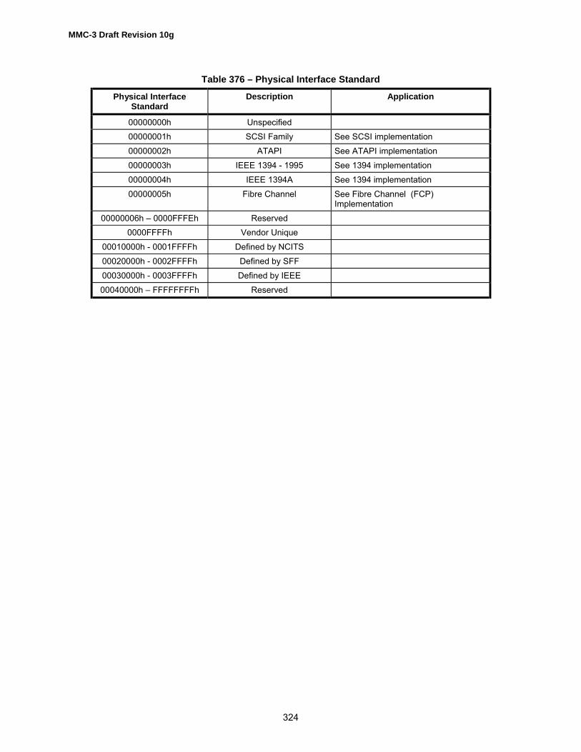
MMC-3 Draft Revision 10g
324
Table 376 – Physical Interface Standard
Physical InterfaceStandard
Description Application
00000000h Unspecified00000001h SCSI Family See SCSI implementation00000002h ATAPI See ATAPI implementation00000003h IEEE 1394 - 1995 See 1394 implementation00000004h IEEE 1394A See 1394 implementation00000005h Fibre Channel See Fibre Channel (FCP)
Implementation00000006h � 0000FFFEh Reserved
0000FFFFh Vendor Unique00010000h - 0001FFFFh Defined by NCITS00020000h - 0002FFFFh Defined by SFF00030000h - 0003FFFFh Defined by IEEE00040000h � FFFFFFFFh Reserved

MMC-3 Draft Revision 10g
325
6.4.3.3 Morphing Feature (0002h)This Feature identifies the ability of the Logical Unit to notify an Initiator about operational changes andaccept Initiator requests to prevent operational changes. Logical Units that support this Feature shallimplement the commands specified in Table 377.
Table 377 – Morphing Feature Commands
Op Code Command Description Reference
46h GET CONFIGURATION 5.54Ah GET EVENT/STATUS NOTIFICATION 5.61Eh PREVENT ALLOW MEDIUM REMOVAL
(with Persistent bit set to one)SPC
A2h SEND EVENT when Class 3 Event (External Request) isimplemented.
5.31
Support for this Feature is enabled using the PREVENT ALLOW MEDIUM REMOVAL command(Persistent Bit), and the media status is retrieved using the GET EVENT/STATUS NOTIFICATIONcommand.The Feature descriptor response data to be returned to the Initiator is defined in Table 378.
Table 378 – Morphing Descriptor Format
BitByte
7 6 5 4 3 2 1 0
0 (MSB) Feature Code = 00002h1 (LSB)2 Reserved Version Persistent Current3 Additional Length = 04h4 Reserved ASYNC5 Reserved6 Reserved7 Reserved
The Feature Code field shall be set to 0002h.The Version Field shall be set to 0h.The Persistent bit shall be set to one.The Current bit shall be set to one.The Additional Length field shall be set to 4.The ASYNC bit, when set to zero, indicates that the Logical Unit supports only the polling implementationof GET EVENT/STATUS NOTIFICATION. When set to one, indicates that the Logical Unit supports bothpolling and asynchronous GET EVENT/STATUS NOTIFICATION.

MMC-3 Draft Revision 10g
326
6.4.3.4 Removable Medium Feature (0003h)Implementing this Feature, Logical Units shall have a means of communicating to the Initiator that theuser wants to eject the medium or has inserted a new medium. Logical Units that support the RemovableMedium Feature shall implement the commands specified in Table 379.
Table 379 – Removable Medium Feature Commands
Op Code Command Description Reference
BDh MECHANISM STATUS 5.91Eh PREVENT ALLOW MEDIUM REMOVAL with the
Persistent Prevent bit set to zero.SPC
1Bh START STOP UNIT and load eject (LOEJ) bit SBC
If a changer type Logical Unit uses media status operation, it shall use the following variations. If thechanger Logical Unit supports individual slot load and unload capability, the slot number(s) exhibiting themedia status change shall be reported in the slot fields of the Media Status Event Data. If the changerLogical Unit uses a magazine load mechanism, the slot fields shall be set to the start and end slotnumbers present in the magazine.For non-immediate GET EVENT/STATUS NOTIFICATION commands, the Initiator shall use exactly oneGET EVENT/STATUS NOTIFICATION request for the entire changer Logical Unit. The Logical Unit shallrespond as indicated in the Asynchronous Operation section above, indicating the slot information in theRequest Sense Data as described above.This Feature identifies a Logical Unit that has a medium that is removable. The Feature descriptorresponse data to be returned is defined in Table 380.
Table 380 – Removable Medium Feature Descriptor Format
BitByte
7 6 5 4 3 2 1 0
0 (MSB) Feature Code = 0003h1 (LSB)2 Reserved Version Persistent Current3 Additional Length = 04h4 Loading Mechanism Type Reserved Eject Pvnt Jmpr Reserved Lock5 Reserved6 Reserved7 Reserved
The Feature Code field shall be set to 0003h.The Version Field shall be set to 0h.The Persistent bit shall be set to one.The Current bit shall be set to one.Event Class 4 shall be supported.The Additional Length field shall be set to 4.The Loading Mechanism Type field (Table 381) shall be set according to the Eject bit. The Eject bit, whenset to zero, indicates that the device cannot eject the medium or magazine via the normal START/STOP

MMC-3 Draft Revision 10g
327
command with the LoEj bit set. When set to one, indicates that the device can eject the medium ormagazine.The Pvnt Jmpr bit, when set to zero, shall indicate that the Prevent Jumper is present. The Logical Unitshall power up to the allow state and locking the Logical Unit with the PREVENT ALLOW MEDIUMREMOVAL command shall not prevent insertion of the media. When set to one, the Prevent Jumper isnot present. The Logical Unit shall power up to the prevent state (locked) and shall not accept new mediaor allow the ejection of media already loaded until a PREVENT ALLOW MEDIUM REMOVAL (allow)command is issued. The Pvnt Jmpr bit shall not change state, even if the physical jumper is added orremoved during operation. Logical Units that do not have a Prevent Jumper available should set this bit to0 to indicate that the Logical Unit behaves as described for a jumper being present.The Lock bit, when set to zero, shall indicate that the medium cannot be locked into the Logical Unit.When set to one, shall indicate that the PREVENT ALLOW MEDIUM REMOVAL command is capable ofactually locking the media into the Logical Unit.
Table 381 – Loading Mechanism Type
Loading MechanismType
Description
000b Caddy/Slot type loading mechanism001b Tray type loading mechanism010b Pop-up type loading mechanism011b Reserved100b Embedded changer with individually changeable discs101b Embedded changer using a magazine mechanism
110b - 111b Reserved
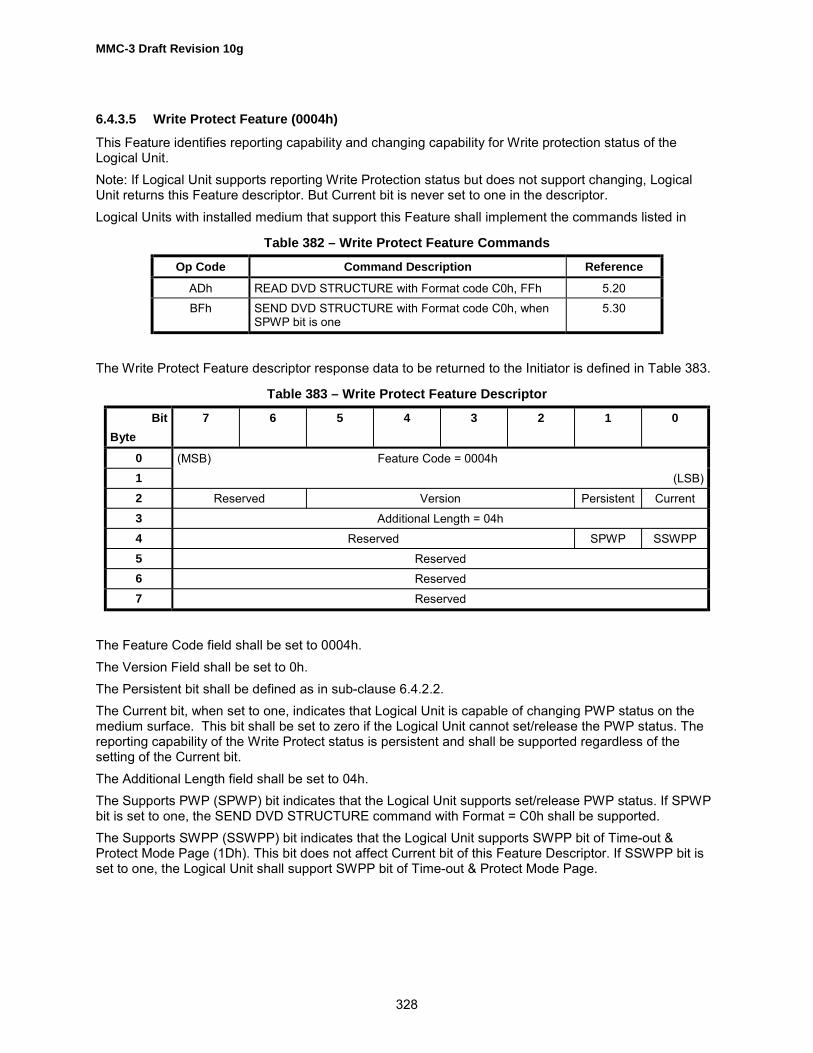
MMC-3 Draft Revision 10g
328
6.4.3.5 Write Protect Feature (0004h)This Feature identifies reporting capability and changing capability for Write protection status of theLogical Unit.Note: If Logical Unit supports reporting Write Protection status but does not support changing, LogicalUnit returns this Feature descriptor. But Current bit is never set to one in the descriptor.Logical Units with installed medium that support this Feature shall implement the commands listed in
Table 382 – Write Protect Feature Commands
Op Code Command Description Reference
ADh READ DVD STRUCTURE with Format code C0h, FFh 5.20BFh SEND DVD STRUCTURE with Format code C0h, when
SPWP bit is one5.30
The Write Protect Feature descriptor response data to be returned to the Initiator is defined in Table 383.
Table 383 – Write Protect Feature Descriptor
BitByte
7 6 5 4 3 2 1 0
0 (MSB) Feature Code = 0004h1 (LSB)2 Reserved Version Persistent Current3 Additional Length = 04h4 Reserved SPWP SSWPP5 Reserved6 Reserved7 Reserved
The Feature Code field shall be set to 0004h.The Version Field shall be set to 0h.The Persistent bit shall be defined as in sub-clause 6.4.2.2.The Current bit, when set to one, indicates that Logical Unit is capable of changing PWP status on themedium surface. This bit shall be set to zero if the Logical Unit cannot set/release the PWP status. Thereporting capability of the Write Protect status is persistent and shall be supported regardless of thesetting of the Current bit.The Additional Length field shall be set to 04h.The Supports PWP (SPWP) bit indicates that the Logical Unit supports set/release PWP status. If SPWPbit is set to one, the SEND DVD STRUCTURE command with Format = C0h shall be supported.The Supports SWPP (SSWPP) bit indicates that the Logical Unit supports SWPP bit of Time-out &Protect Mode Page (1Dh). This bit does not affect Current bit of this Feature Descriptor. If SSWPP bit isset to one, the Logical Unit shall support SWPP bit of Time-out & Protect Mode Page.

MMC-3 Draft Revision 10g
329
6.4.3.6 Random Readable Feature (0010h)This Feature identifies a Logical Unit that can read data from logical blocks specified in a READcommand. Logical Units that may be used, as Random Readable block devices shall implement thecommands specified in Table 384.
Table 384 – Random Readable Feature Commands
Op Code Command Description Reference
25h READ CAPACITY 5.1628h READ(10) SBC
The Feature descriptor response data to be returned to the Initiator is defined in Table 385.
Table 385 – Random Readable Feature Descriptor Format
BitByte
7 6 5 4 3 2 1 0
0 (MSB) Feature Code = 0010h1 (LSB)2 Reserved Version Persistent Current3 Additional Length = 08h4 (MSB)5 Logical Block Size67 (LSB)8 (MSB) Blocking9 (LSB)
10 Reserved PP11 Reserved
There is no requirement that the addresses, in sequences of reads, occur in any particular order.The Feature Code field shall be set to 0010h.The Version Field shall be set to 0h.The Persistent bit shall be defined as in sub-clause 6.4.2.2.The Current bit shall be defined as in sub-clause 6.4.2.3.The Additional Length field shall be set to 8.The Logical Block Size shall be set to the number of bytes per logical block.The Blocking field shall indicate the number of logical blocks per device readable unit. For most harddisks, this value is 1. For DVD devices, this number is 10h. The Blocking field reported in the FeatureDescriptor is for performance optimization only. Reads of any sector or sector count, shall be allowed.If there is more than one Blocking on the medium possible, the Blocking field shall be set to zero. See theREAD TRACK INFORMATION command for more information.The PP (Page Present) bit, when set to zero, shall indicate that the Read/Write Error Recovery ModePage may not be present. When set to one, shall indicate that the Read/Write Error Recovery Mode Pageis present.

MMC-3 Draft Revision 10g
330
If the PP bit in the Feature Descriptor is set, the TB, RC, PER, DTE, and DCR bits of the Read/Write ErrorRecovery Mode Page shall be supported. An Error Recovery Parameter field of 0 in the Read/Write ErrorRecovery Mode Page shall be supported. Support for other bits and values in the Page is optional. ThisPage shall not change due to medium removal or changes. The changeable fields mask shall not changedue to medium removal or changes. The Initiator shall be able to change changeable values whether ornot media is loaded.

MMC-3 Draft Revision 10g
331
6.4.3.7 Multi-Read Feature (001Dh)The Logical Unit shall conform to the OSTA Multi-Read specification 1.00, with the exception of CD Playcapability (the CD Audio Feature is not required). Reading of CD Audio data via the READ CD commandshall be supported. Logical Units that support the Multi-Read Feature shall implement the commandsspecified in Table 386
Table 386 – Multi-Read Feature Commands
Op Code Command Description Reference
28h READ (10) SBCBEh READ CD 5.1651h READ DISC INFOROMATION 5.1952h READ TRACK INFORMATION 5.24
The Feature descriptor response data to be returned to the Initiator is defined in Table 387.
Table 387 – Multi-Read Feature Descriptor Format
BitByte
7 6 5 4 3 2 1 0
0 (MSB) Feature Code = 001Dh1 (LSB)2 Reserved Version Persistent Current3 Additional Length = 00h
The Feature Code field shall be set to 001Dh.The Version Field shall be set to 0h.The Persistent bit shall be defined as in sub-clause 6.4.2.2.The Current bit shall be defined as in sub-clause 6.4.2.3.The Additional Length field shall be set to 00h.
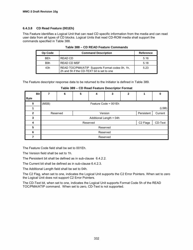
MMC-3 Draft Revision 10g
332
6.4.3.8 CD Read Feature (001Eh)This Feature identifies a Logical Unit that can read CD specific information from the media and can readuser data from all types of CD blocks. Logical Units that read CD-ROM media shall support thecommands specified in Table 388.
Table 388 – CD READ Feature Commands
Op Code Command Description Reference
BEh READ CD 5.16B9h READ CD MSF 5.1843h READ TOC/PMA/ATIP Supports Format codes 0h, 1h,
2h and 5h if the CD-TEXT bit is set to one5.23
The Feature descriptor response data to be returned to the Initiator is defined in Table 389.
Table 389 – CD Read Feature Descriptor Format
BitByte
7 6 5 4 3 2 1 0
01
(MSB) Feature Code = 001Eh(LSB)
2 Reserved Version Persistent Current3 Additional Length = 04h4 Reserved C2 Flags CD-Text5 Reserved6 Reserved7 Reserved
The Feature Code field shall be set to 001Eh.The Version field shall be set to 1h.The Persistent bit shall be defined as in sub-clause 6.4.2.2.The Current bit shall be defined as in sub-clause 6.4.2.3.The Additional Length field shall be set to 04h.The C2 Flag, when set to one, indicates the Logical Unit supports the C2 Error Pointers. When set to zerothe Logical Unit does not support C2 Error Pointers.The CD-Text bit, when set to one, indicates the Logical Unit supports Format Code 5h of the READTOC/PMA/ATIP command. When set to zero, CD-Text is not supported.

MMC-3 Draft Revision 10g
333
6.4.3.9 DVD Read Feature (001Fh)This Feature identifies a Logical Unit that can read DVD specific information from the media. Logical Unitsthat read DVD-ROM media shall support the commands specified in Table 390.
Table 390 – DVD READ Feature Commands
Op Code Command Description Reference
18h READ(10) SBCA8h READ(12) SBCADh READ DVD STRUCTURE 5.2043h READ TOC/PMA/ATIP 5.23
The Feature descriptor response data to be returned to the Initiator is defined in Table 391.
Table 391 – DVD Read Feature Descriptor Format
BitByte
7 6 5 4 3 2 1 0
01
(MSB) Feature Code = 001Fh(LSB)
2 Reserved Version Persistent Current3 Additional Length = 00h
The Feature Code field shall be set to 001Fh.The Version Field shall be set to 0h.The Persistent bit shall be defined as in sub-clause 6.4.2.2.The Current bit shall be defined as in sub-clause 6.4.2.3.The Additional Length field shall be set to 0.

MMC-3 Draft Revision 10g
334
6.4.3.10 Random Writable Feature (0020h)This Feature identifies a Logical Unit that can write data to logical blocks specified by a Write command.There is no requirement that the addresses in sequences of writes occur in any particular order. LogicalUnits that may be used as a random writable block device shall implement the commands as specified inTable 392.
Table 392 – Random Writable Feature Commands
Op Code Command Description Reference
25h READ CAPACITY 5.162Ah WRITE (10) 5.392Eh WRITE AND VERIFY (10) 5.4135h SYNCHRONIZE CACHE
The Immediate bit shall be supported.5.38
The Feature descriptor response data to be returned to the Initiator is defined in Table 393
Table 393 – Random Writable Feature Descriptor Format
BitByte
7 6 5 4 3 2 1 0
0 (MSB) Feature Code = 0020h1 (LSB)2 Reserved Version Persistent Current3 Additional Length = 0Ch4 (MSB)5 Last Logical Block Address67 (LSB)8 (MSB)9 Logical Block Size
1011 (LSB)12 (MSB) Blocking13 (LSB)14 Reserved PP15 Reserved
The Feature Code field shall be set to 0020h.The Version field shall be set to 1h.The Persistent bit shall be defined as in sub-clause 6.4.2.2.The Current bit shall be defined as in sub-clause 6.4.2.3.The Additional Length field shall be set to 0Ch.

MMC-3 Draft Revision 10g
335
The Last Logical Block Address is the logical block address of the last addressable block on the medium.The Logical Block Size field specifies the number of bytes per logical block. This value shall be thesame as reported by the Random Readable Feature and the READ CAPACITY command.The Blocking field shall indicate the number of logical blocks per writable Logical Unit. For most harddisks, this value is 1. For DVD devices, this number is 10h. The Blocking field reported in the FeatureDescriptor is for performance optimization only. Writes of any sector or sector count, shall be allowed.If there is more than one Blocking on the medium possible, the Blocking field shall be set to zero. See theREAD TRACK INFORMATION command for more information.The PP (Page Present) bit, when set to zero, shall indicate that the Read/Write Error Recovery ModePage may not be present. When set to one, shall indicate that the Read/Write Error Recovery Mode Pageis present.

MMC-3 Draft Revision 10g
336
6.4.3.11 Incremental Streaming Writable (0021h)This Feature identifies a Logical Unit that can write data to a contiguous region, and can append data to alimited number of locations on the media. On CD media, this is known as packet recording and on DVDmedia it is known as Incremental Recording. Logical Units that support this Feature shall implement thecommands shown in Table 394.
Table 394 – Incremental Streaming Writable Feature Commands
Op Code Command Description Reference
A1h BLANK (Note 1) 5.25Bh CLOSE TRACK/SESSION 5.351h READ DISC INFORMATION 5.1952h READ TRACK INFORMATION 5.2453h RESERVE TRACK 5.2754h SEND OPC INFORMATION (Note 2) 5.332Ah WRITE (10) 5.3935h SYNCHRONIZE CACHE 5.38
Notes:1. Shall be supported if the Erasable bit in READ DISC INFORMATION, returned data, is setto one. If supported, Blanking Types 000b, 001b, and 100b shall be supported for CD andBlanking Types 000b and 001b shall be supported for DVD.2. Shall be supported if the OPC information is ever returned in the READ DISCINFORMATION return data.
Table 395 – Incremental Streaming Writable Feature Parameters
Page Code Mode page Reference
05h Write Parameters 6.3.5
The Feature descriptor response data is defined in Table 396.

MMC-3 Draft Revision 10g
337
Table 396 – Incremental Streaming Writable Feature Descriptor Format
BitByte
7 6 5 4 3 2 1 0
0 (MSB) Feature Code = 0021h1 (LSB)2 Reserved Version Persistent Current3 Additional Length4 (MSB) Data Block Types Supported5 (LSB)6 Reserved BUF7 Number of Link Sizes
8 - n Link Sizen - ? Pad
The Feature Code field shall be set to 0021h.The Version field is set to 1h.The Persistent bit shall be defined as in sub-clause 6.4.2.2.The Current bit shall be defined as in sub-clause 6.4.2.3.The Additional Length field shall be set to 4 + (Number of Link Sizes) + (Number of Pad bytes).The Data Type Supported field is a bit field that identifies the supported Data Type. A bit set to zeroindicates the Data Type is not supported. A bit set to one indicates the Data Type is supported. Bit 0equates to Data Type 0 and bit 15 equates to Data Type 15, etc.The BUF bit, if set to 1, shall indicate that the Logical Unit is capable of zero loss linking.The Number of Link Sizes shall specify the number of link sizes available for the current media. For CDand DDCD media, this field should be 1. For DVD-R, this field should be 2.Each Link Size field shall indicate the number of logical blocks per link. Links occur on sequentially writtenmedia between independent write operations. The link size does not include any logical blocks written bythe Logical Unit to satisfy the writable unit specified by the Blocking field in the Random ReadableFeature. This field is 7 for CD-R and DDCD-R media, and may be 0, 1, or 16 for DVD media. Link Sizefields are reported by the Logical Unit in the Logical Unit�s preferred order, most desirable first.The Pad field shall contain zeros. The number of Pad bytes shall be 4 * IP((Number of Link Sizes + 3)/4) -(Number of Link Sizes), where IP() is the integer part of the number. The Pad field is present to make thelength of the Feature Descriptor a multiple of 4 bytes.

MMC-3 Draft Revision 10g
338
6.4.3.12 Sector Erasable Feature (0022h)This Feature identifies a Logical Unit that supports erasable media and media that requires an erase passbefore overwrite, such as some magneto-optical technologies. Logical Units that support this Featureshall implement the commands listed in Table 397.Note: This Feature does not apply to DVD-RAM/-RW or DVD+RW, that is a direct overwrite technology.
Table 397 – Sector Erasable Feature Commands
Op Code Command Description Reference
2Ch ERASE(10) SBC2Fh VERIFY(10) (Note 1) SBC2Ah WRITE(10) (Note 2) 5.39
Notes:1. The BLKVFY bit shall be supported2. The EBP bit shall be supported
The Feature descriptor response data to be returned to the Initiator is defined in Table 398.
Table 398 – Sector Erasable Feature Descriptor Format
BitByte
7 6 5 4 3 2 1 0
0 (MSB) Feature Code = 0022h1 (LSB)2 Reserved Version Persistent Current3 Additional Length
The Feature Code field shall be set to 0022h.The Version field shall be set to 0h.The Persistent bit shall be defined as in sub-clause 6.4.2.2.The Current bit shall be defined as in sub-clause 6.4.2.3.The Additional Length field shall be set to 00h.

MMC-3 Draft Revision 10g
339
6.4.3.13 Formattable Feature (0023h)This Feature identifies a Logical Unit that can format media into logical blocks. Logical Units that usemedia that may be formatted shall implement the commands specified in Table 399.
Table 399 – Formattable Feature Commands
Op Code Command Description Reference
04h FORMAT UNIT with a Format Code of 001b, FormatType 0h
5.2
23h READ FORMAT CAPACITIES 5.2103h REQUEST SENSE SPC2Fh VERIFY(10) SBC
The Feature descriptor response data to be returned to the Initiator is defined in Table 400.
Table 400 – Formattable Feature Descriptor Format
BitByte
7 6 5 4 3 2 1 0
0 (MSB) Feature Code = 0023h1 (LSB)2 Reserved Version Persistent Current3 Additional Length = 00h
The Feature Code field shall be set to 0023h.The Version field shall be set to 0h.The Persistent bit shall be defined as in sub-clause 6.4.2.2.The Current bit shall be defined as in sub-clause 6.4.2.3.The Additional Length field shall be set to 0.

MMC-3 Draft Revision 10g
340
6.4.3.14 Defect Management Feature (0024h)This Feature identifies a Logical Unit that shall have defect management available to provide a defect-free contiguous address space. Logical Units that support this Feature shall implement the parameterlisted in Table 401.
Table 401 – Defect Management Feature Parameters
Page Code Parameter Reference
01h CD/DVD Read/Write Error Recovery Mode Page 6.3.4
Note: The AWRE and ARRE shall be supported if medium is Writable.The Feature descriptor response data to be returned to the Initiator is defined in Table 402.
Table 402 – Defect Management Feature Descriptor Format
BitByte
7 6 5 4 3 2 1 0
0 (MSB) Feature Code = 0024h1 (LSB)2 Reserved Version Persistent Current3 Additional Length = 04h4 SSA Reserved5 Reserved6 Reserved7 Reserved
The Feature Code field shall be set to 0024h.The Version Field shall be set to 1h.The Persistent bit shall be defined as in sub-clause 6.4.2.2.The Current bit shall be defined as in sub-clause 6.4.2.3.The Additional Length field shall be set to 4h.
An SSA bit of one shall indicate that the Logical Unit supports the READ DVD STRUCTURE commandwith Format Code 0Ah (Spare Area Information).

MMC-3 Draft Revision 10g
341
6.4.3.15 Write Once Feature (0025h)This Feature identifies a Logical Unit that shall have the ability to record to any previously unrecordedlogical block. The recording of logical blocks may occur in any order. Previously recorded blocks shall notbe overwritten. Logical Units that support this Feature shall implement the commands listed in Table 403.
Table 403 – Write Once Feature Commands
Op Code Command Description Reference
25h READ CAPACITY 5.1635h SYNCHRONIZE CACHE 5.382Ah WRITE(10) 5.392Eh WRITE AND VERIFY (10) 5.41
Table 404 – Write Once Feature Parameters
Page Code Parameter Reference
01h CD/DVD Read/Write Error Recovery Mode Page 6.3.4
The Feature descriptor response data to be returned to the Initiator is defined in Table 405.
Table 405 – Write Once Feature Descriptor Format
BitByte
7 6 5 4 3 2 1 0
0 (MSB) Feature Code = 00025h1 (LSB)2 Reserved Version Persistent Current3 Additional Length = 08h4 (MSB)5 Logical Block Size67 (LSB)8 (MSB) Blocking9 (LSB)
10 Reserved PP11 Reserved
The Feature Code field shall be set to 25h.The Version field shall be set to 0h.The Persistent bit shall be defined as in sub-clause 6.4.2.2.The Current bit shall be defined as in sub-clause 6.4.2.3.The Additional Length field shall be set to 08h.

MMC-3 Draft Revision 10g
342
The Logical Block Size is the number of bytes per logical block. This value shall be the same as reportedby the Random Readable Feature and the READ CAPACITY command.The Blocking field shall indicate the number of logical blocks per Logical Unit writable unit. For most harddisks, this value is 1. For DVD devices, this number is 10h. The Blocking field reported in the FeatureDescriptor is for performance optimization only. Writes of any sector or sector count shall be allowed.If there is more than one Blocking on the medium possible, the Blocking field shall be set to zero. See theREAD TRACK INFORMATION command for more information.The PP (Page Present) bit, when set to zero, shall indicate that the Read/Write Error Recovery ModePage may not be present. When set to one, shall indicate that the Read/Write Error Recovery Mode Pageis present.

MMC-3 Draft Revision 10g
343
6.4.3.16 Restricted Overwrite Feature (0026h)This Feature identifies a Logical Unit that shall have the ability to overwrite logical blocks only in fixed setsat a time. Logical Units that write and read CD-RW and DDCD-RW media shall support the commandsspecified inTable 406.
Table 406 – Restricted Overwrite Feature Commands
Op Code Command Description Reference
25h READ CAPACITY 5.1651h READ DISC INFORMATION 5.1952h READ TRACK INFORMATION 5.2435h SYNCHRONIZE CACHE 5.382Ah WRITE(10) 5.39
Table 407 – Restricted Overwrite Feature Parameter
Page Code Parameter Reference
05h Write Parameter Page 6.3.5
The Feature descriptor response data to be returned to the Initiator is defined in Table 408.
Table 408 – Restricted Overwrite Feature Descriptor Format
BitByte
7 6 5 4 3 2 1 0
0 (MSB) Feature Code = 0026h1 (LSB)2 Reserved Version Persistent Current3 Additional Length = 00h
The Feature Code field shall be set to 0026h.The Version field shall be set to 0h.The Persistent bit shall be defined as in sub-clause 6.4.2.2. This bit shall be set to zero if the medium isremovable.The Current bit shall be defined as in sub-clause 6.4.2.3. This bit shall be set to zero if RestrictedOverwrite medium is not present.The Additional Length field shall be set to 0.

MMC-3 Draft Revision 10g
344
6.4.3.17 CD-RW CAV Write Feature (0027h)This Feature identifies a Logical Unit that has the ability to perform writing on CD-RW media in CAVmode. The Logical Unit shall conform to the Orange Book Part 3 Volume 2 specification. This Featureshall not be current if high-speed recordable CD-RW media is not mounted. Logical Unit with writeprotected media shall not have this Feature current. Logical Units with installed medium that support thisFeature shall implement the commands listed in Table 409.
Table 409 – CD-RW CAV Write Feature Commands
Op Code Command Description Reference
25h READ CAPACITY 5.1651h READ DISK INFORMATION 5.1952h READ TRACK INFORMATION 5.2435h SYNCHRONIZE CACHE 5.382Ah WRITE (10) 5.39
Table 410 – CD-RW CAV Write Feature Parameters
Page Code Parameter Reference
05h Write Parameters Page 6.3.5
The CD-RW CAV Write Feature descriptor response data to be returned to the Initiator is defined in Table411.
Table 411 – CD-RW CAV WRITE Feature Descriptor
BitByte
7 6 5 4 3 2 1 0
0 (MSB) Feature Code = 0027h1 (LSB)2 Reserved Version Persistent Current3 Additional Length = 04h4 Reserved5 Reserved6 Reserved7 Reserved
The Feature Code field shall be set to 0027h.The Version field shall be set to 0.The Persistent bit shall be defined as in sub-clause 6.4.2.2.The Current bit shall be defined as in sub-clause 6.4.2.3.The Additional Length field shall be set to 04h.

MMC-3 Draft Revision 10g
345
6.4.3.18 The MRW Feature (0028h)The presence of the MRW Feature indicates that the Logical Unit is capable of reading a disc with theMRW format.
Table 412 – MRW Feature Descriptor
BitByte
7 6 5 4 3 2 1 0
01
Feature Code = 0028h
2 Reserved Version Persistent Current3 Additional Length = 44 Reserved Write5 Reserved6 Reserved7 Reserved
The Version field shall be set to 0.The Persistent bit shall be defined as in sub-clause 6.4.2.2.The Current bit shall be defined as in sub-clause 6.4.2.3.
Note: Since MRW medium is removable, Persistent is cleared to zero. When Current is cleared tozero, either no disc is mounted or the disc currently mounted is not a MRW disc. WhenCurrent is set to 1, a disc is mounted and it is a MRW disc.
The Additional Length field shall be set to 04h.If the Write bit is cleared to zero, then no additional capability is claimed.If the Write bit is set to one, then the Logical Unit is also capable of formatting discs in the MRW formatand is capable of writing discs that have been MRW formatted. When the Write bit is set to one, then theLogical Unit shall include the Removable Disk Profile and list all features required of that profile.Logical Units that support this feature shall implement the commands listed in Table 413.
Table 413 – MRW Feature Commands
Op Code Command Description Reference
25h READ CAPACITY 5.164Ah GET EVENT/STATUS NOTIFICATION 5.651h READ DISK INFORMATION 5.1928h READ (10) SBC

MMC-3 Draft Revision 10g
346
Logical Units that support this feature shall implement the mode pages listed in Table 413.
Table 414 – MRW Feature Parameters
Page Code Parameter Reference
2Ch MRW Mode Page 5.5.11
Logical Units that support this feature and its write capabilities shall implement the commands listed inTable 415 in addition to the commands listed in Table 413.
Table 415 – MRW Write Feature Commands
Op Code Command Description Reference
5Bh CLOSE TRACK/SESSION 5.304h FORMAT UNIT 5.428h WRITE (10) 5.392Eh WRITE AND VERIFY (10) 5.412Fh VERIFY (10) SBC23h READ FORMAT CAPACITIES 5.21

MMC-3 Draft Revision 10g
347
6.4.3.19 DVD+RW Feature (002Ah)The presence of the DVD+RW Feature indicates that the Logical Unit is capable of reading a recordedDVD+RW disc that is formatted according to DVD+RW 4.7 Gbytes Basic Format Specifications. TheDVD+RW Feature descriptor is shown in Table 416.
Table 416 – DVD+RW Feature Descriptor
BitByte
7 6 5 4 3 2 1 0
01
Feature Code = 002Ah
2 Reserved Version Persistent Current3 Additional Length4 Reserved Write5 Reserved Close Only6 Reserved7 Reserved
The Version field shall be set to 0h.The Persistent bit shall be defined as in sub-clause 6.4.2.2.The Current bit shall be defined as in sub-clause 6.4.2.3.The Additional Length field shall be set to 04h.This feature may be present only to represent additional capability for the DVD-ROM Profile. If the Writebit is cleared to zero, then no additional capability is claimed. A device may report this feature only whenProfile 10h (DVD-ROM) is reported. No additional commands or mode parameters are required.If the Write bit is set to one, then the Logical Unit is also capable of background formatting DVD+RWdiscs according to DVD+RW 4.7 Gbytes Basic Format Specifications and is capable of writing DVD+RWdiscs that have been formatted according to DVD+RW 4.7 Gbytes Basic Format Specifications.If the Close Only bit is cleared to zero, then the drive supports both forms of background format stop. Ifthe Close Only bit is set to one, then the drive supports only the read compatibility stop.If a Logical Unit reports this feature with the Write bit is set to one, then it shall support the commandsshown in Table 417.
Table 417 – Command Support Required by the DVD+RW Feature with Write
Op Code Command Description Reference
5Bh Close Track/Session 5.304h Format Unit 5.4
BFh Send DVD Structure 5.302Ah Write-10 5.39
2Eh Write and Verify-10 SBC
AAh Write-12 5.40
The Send DVD Structure Command must support format field values 05h and 30h.

MMC-3 Draft Revision 10g
348
6.4.3.20 Rigid Restricted Overwrite Feature (002Ch)This Feature identifies a Logical Unit that has the ability to perform writing only on Blocking boundaries.This Feature is different from the Restricted Overwrite Feature (0026h) because each Write command isalso required to end on a Blocking boundary. This Feature replaces the Random Writable Feature forLogical Units that do not perform read-modify-write operations on write requests smaller than Blocking.This Feature shall not be current if the Random Writable Feature is current. This Feature may be presentwhen DVD-RW Restricted Over writable media is loaded. Logical Units with write protected media shallnot have this Feature current. If this Feature is current, the Random Writable Feature shall not be current.If more than one Track/Session is present on the media, the initiator should use the READ DISCINFORMATION and READ TRACK INFORMATION commands to obtain a description of the mediumsuch as Blocking factor.Writing from the initiator into the media shall be in units of Blocking. Writing shall begin and shall stop atBlocking boundaries. The writable units may be sent via multiple WRITE (10) commands. If a Write doesnot begin on a Blocking boundary, the Logical Unit shall return CHECK CONDITION status and setSK/ASC/ASCQ values to ILLEGAL REQUEST/INVALID ADDRESS FOR WRITE. If a Write does not endon a Blocking boundary the Logical Unit shall return CHECK CONDITION status and set SK/ASC/ASCQvalues to ILLEGAL REQUEST/INVALID FIELD IN CDB.Logical Units that support this Feature shall implement the commands and Features identified in Table418.
Table 418 – Rigid Restricted Overwrite Feature Commands
Op Code Command Description Reference
A1h BLANK with Blanking Type = 00h, 01h (Note 1) 5.2ACh GET PERFORMANCE with Type =2 (Note 2) 5.751h READ DISC INFORMATION 5.1952h READ TRACK INFORMATION 5.2425h READ CAPACITY 5.1635h SYNCHRONIZE CACHE 5.382Fh VERIFY (10) SBC2Ah WRITE (10) 5.39
Notes:1. Shall be implemented if the Blank bit = 1.2. Shall be implemented if the DSDR bit = 1.
The Feature descriptor response data is defined in Table 419.

MMC-3 Draft Revision 10g
349
Table 419 – Rigid Restricted Overwrite Feature Descriptor Format
BitByte
7 6 5 4 3 2 1 0
0 (MSB) Feature Code = 002Ch1 (LSB)2 Reserved Version Persisten
tCurrent
3 Additional Length = 04h4 Reserved DSDG DSDR Inter-
mediateBlank
5 Reserved6 Reserved7 Reserved
The Feature Code field shall be set to 002Ch.The Version field shall be set to 0h.The Persistent bit shall be defined as in sub-clause 6.4.2.2.The Current bit shall be defined as in sub-clause 6.4.2.3.The Additional Length field shall be set to 04h.The Defect Status Data Generate (DSDG) bit, if set to 1, shall indicate that the Logical Unit supports togenerate Defect Status data during formatting. A disable certification (DCRT) bit of Table 60 shall besupported. If set to 0, shall indicate that the Logical Unit does not support generating of Defect StatusBitmap.The Defect Status Data Read (DSDR) bit, if set to 1, shall indicate that the Logical Unit supports to readDefect Status data recorded on a medium. A disable certification (DCRT) bit of Table 60 shall besupported. If set to 0, shall indicate that the Logical Unit does not support reading of Defect Status data.The Intermediate bit, if set to 1, shall indicate that the Logical Unit supports writing on an intermediatestate Session and quick formatting (Format Type of 15h - Quick Format). If set to 0, shall indicate that theLogical Unit does not support writing on an intermediate state Session and quick formatting.The Blank bit, if set to 1, shall indicate that the Logical Unit supports BLANK command with BlankingType 00h and 01h. If set to 0, shall indicate that the Logical Unit does not support BLANK command.

MMC-3 Draft Revision 10g
350
6.4.3.21 CD Track at Once Feature (002Dh)This Feature identifies a Logical Unit that can write data to a CD track. Logical Units that support thisFeature shall implement the commands and Features identified in Table 420.
Table 420 – CD Track at Once Feature Commands
Op Code Command Description Reference
A1h BLANK (Note 1) 5.25Bh CLOSE TRACK/SESSION 5.351h READ DISC INFORMATION 5.1952h READ TRACK INFORMATION 5.2453h RESERVE TRACK 5.2754h SEND OPC INFORMATION (Note 2) 5.3335h SYNCHRONIZE CACHE 5.382Ah WRITE (10) 5.39
Notes:1. Shall be implemented if the Erasable bit, in the READ DISC INFORMATION returned data,is set to one. If supported, Blanking Type 000b, 001b, and 100b shall be supported.2. Shall be implemented if OPC Information is returned in the READ DISC INFORMATIONreturned data.
Table 421 – CD Track at Once Feature Parameters
Page Code Parameter Reference
05h Write Parameters Page 6.3.5
The Feature descriptor response data to be returned to the Initiator is defined in Table 422.
Table 422 – CD Track at Once Feature Descriptor Format
BitByte
7 6 5 4 3 2 1 0
0 (MSB) Feature Code = 002Dh1 (LSB)2 Reserved Version = 2h Persistent Current3 Additional Length = 04h4 Resvd BUF Resvd R-W
RawR-WPack
Test Write CD-RW R-WSub-code
5 Reserved6 (MSB) Data Type Supported7 (LSB)
The Feature Code field shall be set to 002Dh.The Version Field shall be set to 2h.The Persistent bit shall be defined as in sub-clause 6.4.2.2.The Current bit shall be defined as in sub-clause 6.4.2.3.

MMC-3 Draft Revision 10g
351
The Additional Length field shall be set to 04h.The following bits indicate Feature support. If set to zero, the Feature is not supported. If set to one, theFeature is supported.The BUF bit, if set to 1, shall indicate that the Logical Unit is capable of zero loss linking.The R-W Raw bit, if set to 1, shall indicate that the Logical Unit supports writing R-W Sub code in the Rawmode. The R-W Sub-code bit shall be set if this bit is set.The R-W Pack bit, if set to 1, shall indicate that the Logical Unit supports writing R-W Sub code in thePacked mode. The R-W Sub-code bit shall be set if this bit is set.The Test Write bit indicates that the Logical Unit can perform test writes. See sub-clause 6.3.5. The CD-RW bit indicates support for overwriting a Track at Once track with another.The R-W Sub-code bit indicates that the Logical Unit can record the R-W Sub-channels with usersupplied data.The Data Type Supported field is defined in sub-clause 6.4.3.11.

MMC-3 Draft Revision 10g
352
6.4.3.22 CD Mastering (Session at Once) Feature (002Eh)This Feature identifies a Logical Unit that can write a CD in Session at Once or Raw mode. Logical Unitsthat support Session at Once mastering shall implement the commands listed in Table 423, andparameters listed in Table 424. Logical Units that support mastering in RAW mode shall implement thecommands listed in Table 425, and parameters listed in Table 426.
Table 423 – CD Mastering (Session at Once) Feature Commands
Op Code Command Description Reference
51h READ DISC INFORMATION 5.1952h READ TRACK INFORMATION 5.245Dh SEND CUE SHEET 5.2954h SEND OPC INFORMATION (Note 1) 5.332Ah WRITE (10) 5.39
Notes:1. Shall be implemented if OPC Information is returned in the READ DISC INFORMATIONreturned data.
Table 424 – CD Mastering (Session at Once) Feature Parameter
Page Code Parameter Reference
05h Write Parameters � Session-At-Once Write type shall besupported.
6.3.5
Table 425 – CD Mastering (RAW) Feature Commands
Op-Code Command Reference
51h READ DISC INFORMATION 5.1952h READ TRACK INFORMATION 5.2435h SYNCHRONIZE CACHE 5.382Ah WRITE (10) 5.39
Table 426 – CD Mastering (RAW) Feature Parameters
Page Code Parameter Reference
05h Write Parameters Page• RAW Write Type shall be supported• Data Block Type 2 and 3 shall be supported when R-
W bit is set to one.
6.3.5

MMC-3 Draft Revision 10g
353
The Feature descriptor response data to be returned to the Initiator is defined in Table 427.
Table 427 – CD Mastering Feature Descriptor
BitByte
7 6 5 4 3 2 1 0
0 (MSB) Feature Code = 002Eh1 (LSB)2 Reserved Version Persistent Current3 Additional Length = 04h4 Resvd BUF SAO RAW MS RAW TEST
WRITECD_RW R-W
5 (MSB)6 Maximum Cue Sheet Length7 (LSB)
The Feature Code field shall be set to 002Eh.The Version Field shall be set to 1h.The Persistent bit shall be defined as in sub-clause 6.4.2.2.The Current bit shall be defined as in sub-clause 6.4.2.3.The Additional Length field shall be set to 04h.The following bits indicate Feature support. If set to zero, the Feature is not supported. If set to one, theFeature is supported.The BUF bit, if set to 1, shall indicate that the Logical Unit is capable of zero loss linking.The SAO bit shall indicate that the Logical Unit can record using the Session at Once write type.The Raw MS bit shall indicate that the Logical Unit can record multi-session in raw mode.The Raw bit shall indicate that the Logical Unit can record using the raw write type.The Test Write bit shall indicate that the Logical Unit can perform test writes.The CD-RW bit shall indicate that the Logical Unit can overwrite previously recorded data.The R-W bit shall indicate that the Logical Unit can record the R-W Sub-channels with user suppliedinformation.The Maximum Cue Sheet Length field indicates the maximum length of a Cue Sheet that can beaccepted by the Logical Unit for Session at Once recording. If the SAO bit is zero, this field shall be set tozero.

MMC-3 Draft Revision 10g
354
6.4.3.23 DVD-R/-RW Write Feature (002Fh)This Feature identifies a Logical Unit that can write data to DVD-R/-RW in Disc at Once mode. LogicalUnits that write and read DVD-R/-RW media shall support the commands specified in Table 428 and theparameters identified in Table 429.
Table 428 – DVD-R/-RW Write Feature Commands
Op Code Command Description Reference
A1h BLANK with Blanking Type 00h and 01h (Note) 5.251h READ DISC INFORMATION 5.1952h READ TRACK INFORMATION 5.2453h RESERVE TRACK 5.27BFh SEND DVD STRUCTURE 5.302Ah WRITE (10) 5.39
Note: Shall be implemented if DVD-RW bit = 1.
Table 429 – DVD-R/-RW Write Feature Parameters
Page Code Parameter Sub-Reference
05h Write Parameter - Session at Once Write Type shall besupported
6.3.5
The DVD-R/-RW Write Feature descriptor response data to be returned to the Initiator is defined in Table430.
Table 430 – DVD-R/-RW Write Feature Descriptor Format
BitByte
7 6 5 4 3 2 1 0
0 (MSB) Feature Code = 002Fh1 (LSB)2 Reserved Version = 1h Persistent Current3 Additional Length = 04h4 Reserved BUF Reserved Test Write DVD-RW Reserved5 Reserved6 Reserved7 Reserved
The Feature Code field shall be set to 002Fh.The Version Field shall be set to 1h.The Persistent bit shall be defined as in sub-clause 6.4.2.2. This bit shall be set to zero if the medium isremovable.The Current bit shall be defined as in sub-clause 6.4.2.3. This bit shall be set to zero if DVD-R/-RWmedia is not present.The Additional Length field shall be set to 04h.

MMC-3 Draft Revision 10g
355
The BUF bit, when set to one, indicates the Logical Unit can perform Buffer Under-run Free recording.The Test Write bit, when set to zero, shall indicate that the Logical Unit is not capable of performing testwrites. When set to one, the Logical Unit is capable of performing test writes.The DVD-RW bit indicates support for writing and erasing on DVD-RW media. If this bit set to one, shallindicate that the Logical Unit supports BLANK command, Blanking Type 00h and 01h.

MMC-3 Draft Revision 10g
356
6.4.3.24 Double Density CD Read Feature (0030h)This Feature identifies a Logical Unit that can read DDCD specific information from the media and canread user data from DDCD blocks.A Logical Unit that read DDCD-ROM media shall support the commands specified in Table 431.
Table 431 – DDCD Read Feature Commands
Op Code Command Description Reference
BEh READ CD 5.1743h READ TOC/PMA/ATIP Supports Format codes 0h, 1h,
2h and 5h if the CD-TEXT bit is set to one5.23
The DDCD Read Feature descriptor response data to be returned to the Initiator is defined in Table 432.
Table 432 – DDCD Read Feature Descriptor Format
BitByte
7 6 5 4 3 2 1 0
01
Feature Code = 0030h
2 Reserved Version Persistent Current3 Additional Length = 00h
Version shall be set to 0h.The Persistent bit shall be defined as in sub-clause 6.4.2.2.The Current bit shall be defined as in sub-clause 6.4.2.3.

MMC-3 Draft Revision 10g
357
6.4.3.25 Double Density CD-R Write Feature (0031h)This Feature identifies a Logical Unit that can write data to DDCD-R. A Logical Unit that writes and readsDDCD-R media shall support the commands specified in Table 433.
Table 433 – DDCD-R Write Feature Commands
Op Code Command Description Reference
51h READ DISC INFORMATION 5.1952h READ TRACK INFORMATION 5.2453h RESERVE TRACK 5.272Ah WRITE (10) 5.39AAh WRITE (12) 5.40
Table 434 – DDCD-R Write Feature Descriptor Format
BitByte
7 6 5 4 3 2 1 0
01
Feature Code = 0031h
2 Reserved Version Persistent Current3 Additional Length = 44 Reserved TestWR Reserved5 Reserved6 Reserved7 Reserved
The Feature Code field shall be set to 0031hThe Version field shall be set to 0h.The Persistent bit shall be defined as in sub-clause 6.4.2.2.The Current bit shall be defined as in sub-clause 6.4.2.3.The Additional Length field shall be set to 04h.The TestWR bit, when set to zero, shall indicate that the Logical Unit is not capable of performing testwrites. When set to one, the Logical Unit shall be capable of performing test writes.
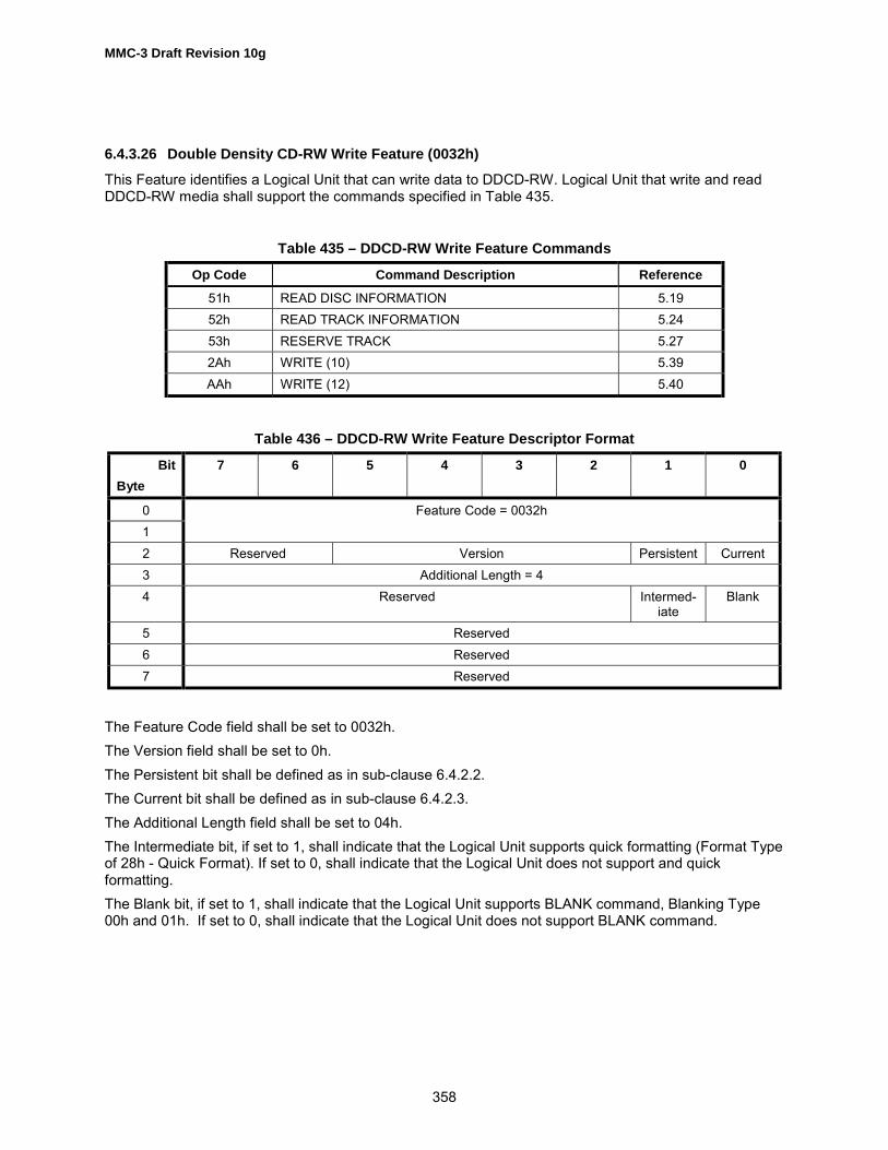
MMC-3 Draft Revision 10g
358
6.4.3.26 Double Density CD-RW Write Feature (0032h)This Feature identifies a Logical Unit that can write data to DDCD-RW. Logical Unit that write and readDDCD-RW media shall support the commands specified in Table 435.
Table 435 – DDCD-RW Write Feature Commands
Op Code Command Description Reference
51h READ DISC INFORMATION 5.1952h READ TRACK INFORMATION 5.2453h RESERVE TRACK 5.272Ah WRITE (10) 5.39AAh WRITE (12) 5.40
Table 436 – DDCD-RW Write Feature Descriptor Format
BitByte
7 6 5 4 3 2 1 0
01
Feature Code = 0032h
2 Reserved Version Persistent Current3 Additional Length = 44 Reserved Intermed-
iateBlank
5 Reserved6 Reserved7 Reserved
The Feature Code field shall be set to 0032h.The Version field shall be set to 0h.The Persistent bit shall be defined as in sub-clause 6.4.2.2.The Current bit shall be defined as in sub-clause 6.4.2.3.The Additional Length field shall be set to 04h.The Intermediate bit, if set to 1, shall indicate that the Logical Unit supports quick formatting (Format Typeof 28h - Quick Format). If set to 0, shall indicate that the Logical Unit does not support and quickformatting.The Blank bit, if set to 1, shall indicate that the Logical Unit supports BLANK command, Blanking Type00h and 01h. If set to 0, shall indicate that the Logical Unit does not support BLANK command.

MMC-3 Draft Revision 10g
359
6.4.3.27 Power Management Feature (0100h)This Feature identifies a Logical Unit that can perform Initiator and Logical Unit directed powermanagement. Logical Units that support this Feature shall implement the commands specified in Table437 and the mode parameters specified in Table 438.
Table 437 – Power Management Feature Commands
Op Code Command Description Reference
4Ah GET EVENT/STATUS NOTIFICATION (Note 1) 5.61Bh START STOP UNIT (Note 2) SBC
Note:1. Power Management Class events shall be supported2. Power Condition field shall be supported
Table 438 – Power Management Feature Parameters
Page Code Page Description Reference
1Ah Power Condition Page 6.3.8
The Feature descriptor response data to be returned to the Initiator is defined in Table 439.
Table 439 – Power Management Feature Descriptor Format
BitByte
7 6 5 4 3 2 1 0
0 (MSB) Feature Code = 0100h1 (LSB)2 Reserved Version Persistent Current3 Additional Length = 00h
The Feature Code field shall be set to 0100h.The Version field shall be set to 0h.The Persistent bit shall be set to one.The Current bit shall be set to one.The Additional Length field shall be set to 0.

MMC-3 Draft Revision 10g
360
6.4.3.28 S.M.A.R.T. Feature (0102h)This Feature identifies a Logical Unit that can perform Self-Monitoring Analysis and ReportingTechnology. S.M.A.R.T. was developed to manage the reliability of data storage Logical Units.S.M.A.R.T.Peripheral data storage Logical Units can suffer performance degradation or failure due to a single eventor a combination of events. Some events are immediate and catastrophic while others cause a gradualdegradation of the Logical Unit�s ability to perform. It is possible to predict a portion of the failures, butS.M.A.R.T. cannot and shall not predict all future Logical Unit failures.It is the responsibility of a S.M.A.R.T. Logical Unit to predict an impending failure and report that failurevia an Informational Exception Condition.
BitByte
7 6 5 4 3 2 1 0
0 (MSB) Feature Code = 0101h1 (LSB)2 Reserved Version Persistent Current3 Additional Length = 04h4 Reserved PP5 Reserved6 Reserved7 Reserved
The Feature Code field shall be set to 0101h.The Version field shall be set to 0h.The Persistent bit shall be defined as in sub-clause 6.4.2.2.The Current bit shall be defined as in sub-clause 6.4.2.3.The Additional Length field shall be set to 04h.If the Page Present (PP) bit is cleared to zero, then the Fault/Failure Reporting Mode Page (1Ch) is notsupported by this Logical Unit.If the Page Present (PP) bit is set to one, then the Fault/Failure Reporting Mode Page (1Ch) is supportedby this Logical Unit.If the Fault / Failure Reporting Mode Page is not supported the Logical Unit shall use the following defaultvalues:1. Performance (Perf ) bit shall be 0 (Delays are acceptable).2. Enable Warning (EWasc) bit shall be 0 (Disable WARNING Sense Code reporting).3. Disable Exception Control (DExcept) bit shall be 0 (Do not Disable reporting of exception conditions).
Test bit shall be 0.4. Method of Reporting Informational Exceptions (MRIE) shall be 4 (Unconditionally generate recovered
error).5. Interval Timer shall be set to 6 000.
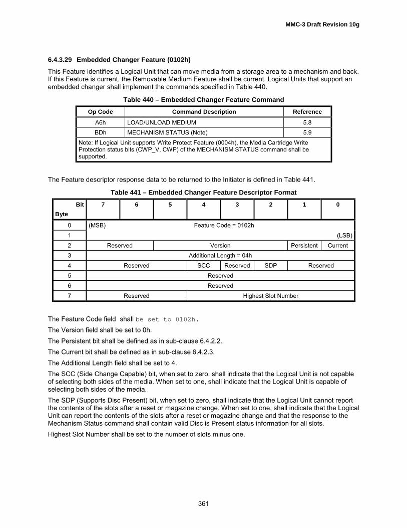
MMC-3 Draft Revision 10g
361
6.4.3.29 Embedded Changer Feature (0102h)This Feature identifies a Logical Unit that can move media from a storage area to a mechanism and back.If this Feature is current, the Removable Medium Feature shall be current. Logical Units that support anembedded changer shall implement the commands specified in Table 440.
Table 440 – Embedded Changer Feature Command
Op Code Command Description Reference
A6h LOAD/UNLOAD MEDIUM 5.8BDh MECHANISM STATUS (Note) 5.9
Note: If Logical Unit supports Write Protect Feature (0004h), the Media Cartridge WriteProtection status bits (CWP_V, CWP) of the MECHANISM STATUS command shall besupported.
The Feature descriptor response data to be returned to the Initiator is defined in Table 441.
Table 441 – Embedded Changer Feature Descriptor Format
BitByte
7 6 5 4 3 2 1 0
0 (MSB) Feature Code = 0102h1 (LSB)2 Reserved Version Persistent Current3 Additional Length = 04h4 Reserved SCC Reserved SDP Reserved5 Reserved6 Reserved7 Reserved Highest Slot Number
The Feature Code field shall be set to 0102h.The Version field shall be set to 0h.The Persistent bit shall be defined as in sub-clause 6.4.2.2.The Current bit shall be defined as in sub-clause 6.4.2.3.The Additional Length field shall be set to 4.The SCC (Side Change Capable) bit, when set to zero, shall indicate that the Logical Unit is not capableof selecting both sides of the media. When set to one, shall indicate that the Logical Unit is capable ofselecting both sides of the media.The SDP (Supports Disc Present) bit, when set to zero, shall indicate that the Logical Unit cannot reportthe contents of the slots after a reset or magazine change. When set to one, shall indicate that the LogicalUnit can report the contents of the slots after a reset or magazine change and that the response to theMechanism Status command shall contain valid Disc is Present status information for all slots.Highest Slot Number shall be set to the number of slots minus one.

MMC-3 Draft Revision 10g
362
6.4.3.30 CD Audio External Play Feature (0103h)This Feature identifies a Logical Unit that can play CD Audio data directly to an external output. LogicalUnits that have a CD-Audio external output shall support the commands specified by Table 442 and themode pages specified in Table 443.A Logical Unit without a CD-Audio output shall respond to a PLAY AUDIO command, that has a transferlength of zero, with CHECK CONDITION status, and set the sense key to ILLEGAL REQUEST. Thisbehavior allows an Initiator to determine if a CD-Audio analog output is supported.
Table 442 – CD-Audio External Play Feature Commands
OpCode Command Description Reference
BDh MECHANISM STATUS 5.94Bh PAUSE/RESUME 5.1045h PLAY AUDIO (10) 5.1147h PLAY AUDIO MSF 5.1343h READ TOC/PMA/ATIP 5.2342h READ SUBCHANNEL 5.222Bh SEEK SBC4Eh STOP PLAY/SCAN 5.37
Table 443 – CD-Audio External Play Feature Parameters
Page Code Page Description Reference
0Eh CD Audio Control Page 6.3.7
The Feature descriptor response data to be returned to the Initiator is defined in Table 444.
Table 444 – CD Audio External Play Feature Descriptor Format
BitByte
7 6 5 4 3 2 1 0
0 (MSB) Feature Code = 0103h1 (LSB)2 Reserved Version Persistent Current3 Additional Length = 04h4 Reserved Scan SCM SV5 Reserved6 (MSB) Number of Volume Levels
7 - n (LSB)
The Feature Code field shall be set to 0103h.The Version field shall be set to 0h.The Persistent bit shall be defined as in sub-clause 6.4.2.2.The Current bit shall be defined as in sub-clause 6.4.2.3.The Additional Length field shall be set to 4.

MMC-3 Draft Revision 10g
363
The Scan bit, when set to one, indicates the SCAN command is supported.The SCM (Separate Channel Mute) bit, when set to zero, shall indicate that all audio channels are mutedsimultaneously.When set to one, shall indicate that each audio channel can be independently muted.The SV (Separate Volume) bit, when set to zero, shall indicate that all audio channels have the samevolume level. When set to one, shall indicate that audio channel volume may be set independently.The Number of Volume Levels shall indicate the number of discrete volume levels supported by theLogical Unit. If the Logical Unit supports only turning audio on and off, the Number of Volume Levels fieldshall be set to 2.

MMC-3 Draft Revision 10g
364
6.4.3.31 Microcode Upgrade Feature (0104h)This Feature identifies a Logical Unit that can upgrade its internal microcode via the interface. LogicalUnits that support microcode upgrades shall implement the commands specified in Table 445.
Table 445 – Microcode Upgrade Feature Command
Op Code Command Description Reference
3Ch READ BUFFER with Mode 011b set SPC3Bh WRITE BUFFER with Mode 111b (Download microcode
with offset and save)SPC
The Feature descriptor response data to be returned to the Initiator is defined in Table 446.
Table 446 – Microcode Upgrade Feature Descriptor Format
BitByte
7 6 5 4 3 2 1 0
0 (MSB) Feature Code = 0104h1 (LSB)2 Reserved Version Persistent Current3 Additional Length = 00h
The Feature Code field shall be set to 0104h.The Version field shall be set to 0h.The Persistent bit shall be defined as in sub-clause 6.4.2.2.The Current bit shall be defined as in sub-clause 6.4.2.3.The Additional Length field shall be set to 0.

MMC-3 Draft Revision 10g
365
6.4.3.32 Time-Out Feature (0105h)This Feature identifies a Logical Unit that can always respond to commands within a set time period. If acommand cannot complete normally within the allotted time, it completes with an error. Logical Units thatsupport this Feature shall support the parameter listed in Table 447.
Table 447 – Time-Out Feature Parameter
Page Code Parameter Reference
1Dh Time-out and Protect Page 6.3.10
Logical Units that support queuing shall support Event Notification Class 6. If queuing is not supported,the current command shall be terminated with CHECK CONDITION status and SK/ASC/ASCQ valuesshall be set to ILLEGAL REQUEST/INSUFFICIENT TIME FOR OPERATION.Event Notification Class 6 shall be supported if queuing is supported.The Feature descriptor response data to be returned to the Initiator is defined in Table 448.
Table 448 – Time-Out Feature Descriptor Format
BitByte
7 6 5 4 3 2 1 0
0 (MSB) Feature Code = 0105h1 (LSB)2 Reserved Version Persistent Current3 Additional Length = 00h
The Feature Code field shall be set to 0105h.The Version field shall be set to 0h.The Persistent bit shall be defined as in sub-clause 6.4.2.2.The Current bit shall be defined as in sub-clause 6.4.2.3.The Additional Length field shall be set to 00h.

MMC-3 Draft Revision 10g
366
6.4.3.33 DVD CSS Feature (0106h)This Feature identifies a Logical Unit that can perform DVD CSS/CPPM authentication and keymanagement. This Feature identifies Logical Units that support CSS for DVD-Video and CPPM for DVD-Audio. The Logical Unit shall maintain the integrity of the keys by only using DVD CSS authentication andkey management procedures. This Feature shall be current only if a media containing CSS-protectedDVD-Video and/or CPPM-protected DVD-Audio content is loaded.Logical Units that support this Feature shall implement the commands specified by Table 449.
Table 449 – DVD CSS Feature Commands
Op Code Command Description Reference
A2h REPORT KEY except KEY Format 010001b (Note) 5.26A3h SEND KEY 5.32ADh READ DVD STRUCTURE with Format Code 02h 5.20
Note: The KEY Format 000100b (TITLE KEY) does not succeed for CPPM protected sectors,since they do not contain a Title Key.
The Feature descriptor response data to be returned to the Initiator is defined in Table 450.
Table 450 – DVD CSS Feature Descriptor Format
BitByte
7 6 5 4 3 2 1 0
0 (MSB) Feature Code 0106h1 (LSB)2 Reserved Version Persistent Current3 Additional Length = 04h4 Reserved5 Reserved6 Reserved7 CSS Version
The Feature Code field shall be set to 0106h.The Version field shall be set to 0h.The Persistent bit shall be defined as in sub-clause 6.4.2.2.The Current bit shall be set to zero if DVD CSS/CPPM media is not present. Otherwise, this bit shall bedefined as in sub-clause 6.4.2.3.The Additional Length field shall be set to 4.The CSS version shall be set to 01h.

MMC-3 Draft Revision 10g
367
6.4.3.34 Real Time Streaming Feature (0107h)This Feature identifies a Logical Unit that can perform reading and writing within Initiator specified (andLogical Unit verified) performance ranges. This Feature also indicates whether the Logical Units supportsthe Stream playback operation. Logical Units that support this Feature shall implement the commandslisted in Table 451.
Table 451 – Real Time Streaming Feature Commands
Op Code Command Description Reference
ACh GET PERFORMANCE with Type field of 00h, and Typefield 01h when SW bit is set to one and Type field of 03hwhen WSPD bit is set to one
5.7
A8h READ (12) 5.145Ch READ BUFFER CAPACITY with Block bit of 1 (Note 1) 5.15B6h SET STREAMING (Note 2) 5.36A7h SET READ AHEAD 5.35AAh WRITE (12) with Streaming bit when SW bit is set to one 5.40
Note:1 � Shall be implemented if RBCB set to 12 - WRC field of SET STREAMING command shall be supported if WSPD bit is set to one.
The Feature descriptor response data to be returned to the Initiator is defined in Table 452.
Table 452 – Real Time Streaming Feature Descriptor Format
BitByte
7 6 5 4 3 2 1 0
0 (MSB) Feature Code = 0107h1 (LSB)2 Reserved Version Persistent Current3 Additional Length =04h4 Reserved RBCB SCS MP2A WSPD SW5 Reserved6 Reserved7 Reserved
The Feature Code field shall be set to 0107h.The Version Field shall be set to 3h.The Persistent bit shall be defined as in sub-clause .The Current bit shall be defined as in sub-clause 6.4.2.3.The Additional Length field shall be set to 04h.The Read Buffer Capacity Block (RBCB) bit indicates that the Logical Unit supports the READ BUFFERCAPACITY command and its Block bit.The Set CD Speed (SCS) bit of one indicates that the Logical Unit supports the SET CD SPEEDcommand. Otherwise, the Logical Unit does not support the SET CD SPEED command.The Mode Page 2A (MP2A) bit of one indicates that the CD/DVD Capabilities & Mechanical Status ModePage (2Ah) with the Logical Unit Write Speed Performance Descriptor Blocks are supported. Otherwise,

MMC-3 Draft Revision 10g
368
the CD/DVD Capabilities & Mechanical Status Mode Page (2Ah), with the Logical Unit Write SpeedPerformance Descriptor Blocks are not supported by the Logical Unit.A Write Speed Performance Descriptor (WSPD) bit of one indicates that the Logical Unit supports theWrite Speed (Type field = 03h) data of GET PERFORMANCE command and the WRC field of SETSTREAMING command. This bit shall be set to one, if Logical Unit supports writing speed selection.A Stream Writing (SW) bit of one indicates that the Logical Unit supports the Stream recording operation.A SW bit of zero indicates that the Logical Unit may not support the Stream recording operation (see4.6.1)
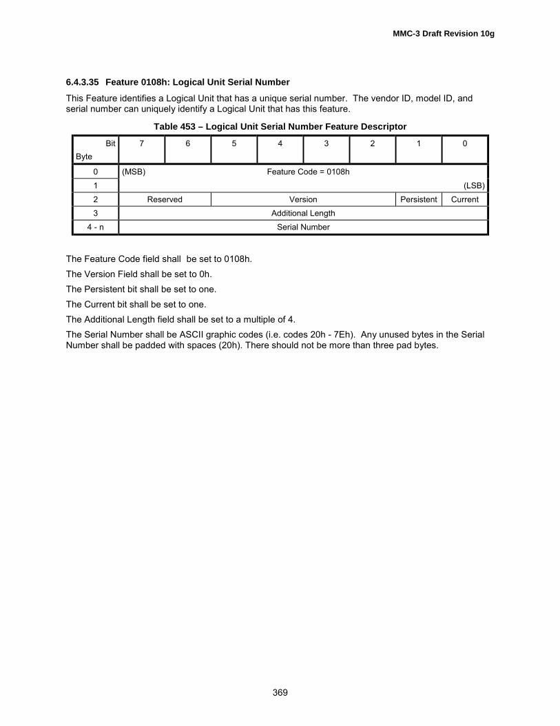
MMC-3 Draft Revision 10g
369
6.4.3.35 Feature 0108h: Logical Unit Serial NumberThis Feature identifies a Logical Unit that has a unique serial number. The vendor ID, model ID, andserial number can uniquely identify a Logical Unit that has this feature.
Table 453 – Logical Unit Serial Number Feature Descriptor
BitByte
7 6 5 4 3 2 1 0
0 (MSB) Feature Code = 0108h1 (LSB)2 Reserved Version Persistent Current3 Additional Length
4 - n Serial Number
The Feature Code field shall be set to 0108h.The Version Field shall be set to 0h.The Persistent bit shall be set to one.The Current bit shall be set to one.The Additional Length field shall be set to a multiple of 4.The Serial Number shall be ASCII graphic codes (i.e. codes 20h - 7Eh). Any unused bytes in the SerialNumber shall be padded with spaces (20h). There should not be more than three pad bytes.

MMC-3 Draft Revision 10g
370
6.4.3.36 Feature 010Ah: Disc Control BlocksThis Feature identifies a Logical Unit that can read and/or write Disc Control Blocks from or to the media.Logical Units that support this Feature shall implement the commands listed in Table 454.
Table 454 – Disc Control Blocks Feature Commands
Op Code Command Description Reference
ADh READ DVD STRUCTUREFormat Code 30h shall be supported.
5.20
BFh SEND DVD STRUCTUREIf any DCB�s are identified as writable, this commandshall be supported.
5.30
Table 455 – Disc Control Blocks Feature Descriptor
BitByte
7 6 5 4 3 2 1 0
0 (MSB) Feature Code = 010Ah1 (LSB)2 Reserved Version Persistent Current3 Additional Length4 (MSB)5 Supported DCB entry 067 (LSB)
n*4 + 4 (MSB)n*4 + 5 Supported DCB entry nn*4 + 6n*4 + 7 (LSB)
The Feature Code field shall be set to 010Ah.The Version Field shall be set to 0h.The Persistent bit shall be defined as in sub-clause 6.4.2.2.The Current bit shall be defined as in sub-clause 6.4.2.3.The Additional Length field shall be set to N * 4, where n is the number of Supported DCB entries. TheSupported DCB entry n fields shall each contain the Content Descriptor of a supported DCB. Entries shallbe sorted in ascending order.

MMC-3 Draft Revision 10g
371
6.4.3.37 Feature 010Bh: DVD CPRMThis Feature identifies a Logical Unit that can perform DVD CPRM and can perform CPRM authenticationand key management.This Feature shall be current only if a DVD CPRM recordable or rewritable medium is loaded. LogicalUnits that support this Feature shall implement the commands listed in Table 456.
Table 456 – DVD CPRM Feature Commands
Op Code Command Description Reference
A2h REPORT KEY 5.26A3h SEND KEY 5.32ADh READ DVD STRUCTURE 5.20
The Feature descriptor response data to be returned to the Initiator is defined in Table 457.
Table 457 – DVD CPRM Feature Descriptor Format
BitByte
7 6 5 4 3 2 1 0
0 (MSB) Feature Code = 010Bh1 (LSB)2 Reserved Version Persistent Current3 Additional Length = 04h4 Reserved5 Reserved6 Reserved7 CPRM version
The Feature Code field shall be set to 010Bh.The Version Field shall be set to zero (0h).The Persistent bit shall be defined as in sub-clause 6.4.2.2.The Current bit shall be defined as in sub-clause 6.4.2.3.The Additional Length field shall be set 04h.The CPRM version field shall be set to 01h.

MMC-3 Draft Revision 10g
372
6.4.4 Profile DefinitionsProfiles define a base set of functions for Logical Units. Logical Units that list a Profile as current shallsupport all Features required by that Profile, but not all Features may be current. Logical Units maysupport Features in addition to those required by the Profile. A single device may implement more thanone Profile, and more than one Profile may be active at any given time. All required Features may not becurrent, depending on the medium installed. If a Not Ready response would be given to a TEST UNITREADY command, no Profile shall be current.For example, a Logical Unit, with unformatted media, may not be able to read or write and thecorresponding Features would not be current. But the Profile corresponding to the Logical Unit/mediasystem may be current, i.e., a DVD-RAM Logical Unit with unformatted media loaded may claimcompliance to the DVD-RAM Profile; a DVD-RAM Logical Unit with no media loaded shall claim no Profileas current.Table 373 shows the list of profiles defined in this document.
6.4.4.1 Profile 1h: Non-Removable Disk
Logical Units identifying Profile 1 as current shall support the Features listed in Table 458.
Table 458 – Mandatory Features for Non-removable Disks
FeatureNumber
Feature Name Description
0000h Profile List A list of all Profiles supported by the device0001h Core Basic Functionality0010h Random Readable, PP=1 Read ability for storage devices with random addressing.0020h Random Writable Write support for randomly addressed writes0024h Defect Management Ability of the Logical Unit/media system to provide an apparently defect-
free space0100h Power Management Initiator and device directed power management0101h SMART Self Monitoring Analysis and Reporting Technology (Failure prediction)
6.4.4.2 Profile 2h: Removable Disk
Logical Units identifying Profile 2 as current shall support the Features listed in Table 459.
Table 459 – Mandatory Features for Removable Disks
FeatureNumber
Feature Name Description
0000h Profile List A list of all Profiles supported by the device0001h Core Basic Functionality0002h Morphing The device changes its operational behavior due to external events0003h Removable Medium The medium may be removed from the device0010h Random Readable, PP=1 Read ability for storage devices with random addressing.0020h Random Writable Write support for randomly addressed writes0023h Formattable Support for formatting of media0024h Defect Management Ability of the Logical Unit/media system to provide an apparently defect-
free space0100h Power Management Initiator and device directed power management0105h Timeout Ability to respond to all commands within a specific time
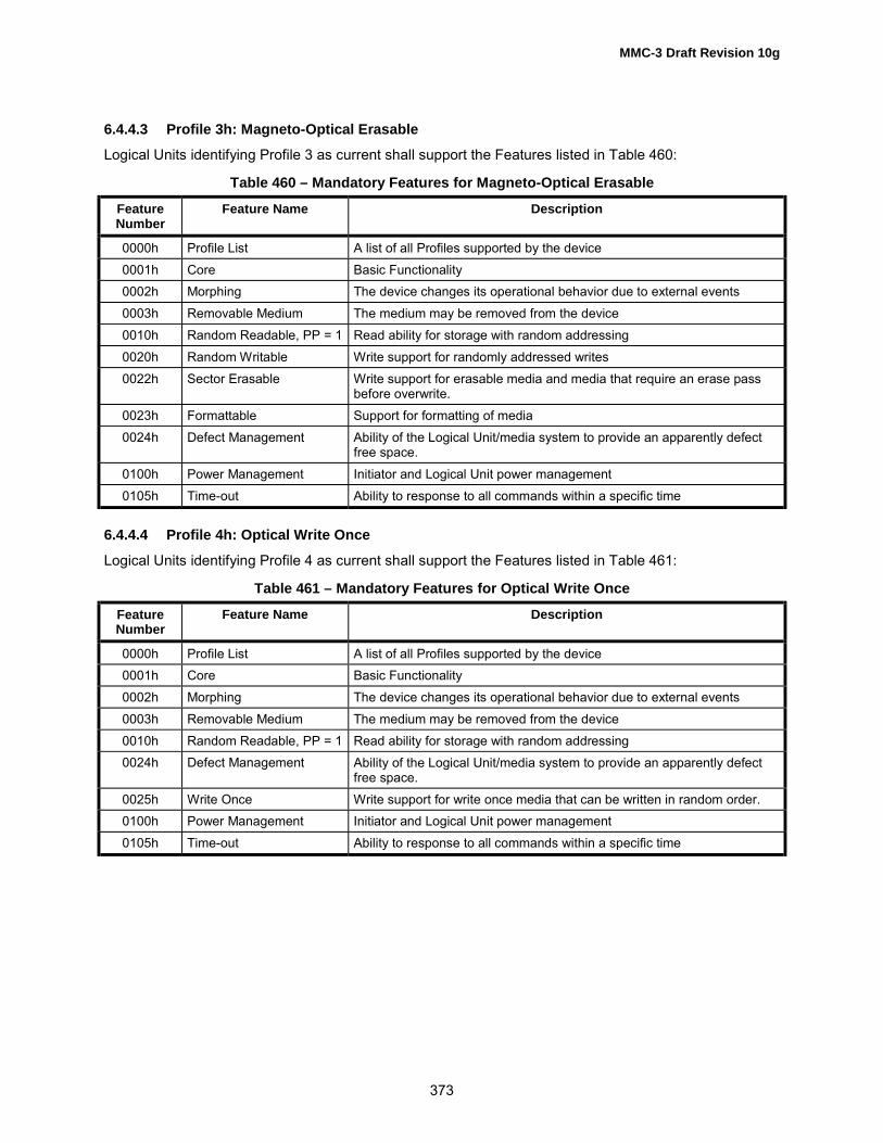
MMC-3 Draft Revision 10g
373
6.4.4.3 Profile 3h: Magneto-Optical ErasableLogical Units identifying Profile 3 as current shall support the Features listed in Table 460:
Table 460 – Mandatory Features for Magneto-Optical Erasable
FeatureNumber
Feature Name Description
0000h Profile List A list of all Profiles supported by the device0001h Core Basic Functionality0002h Morphing The device changes its operational behavior due to external events0003h Removable Medium The medium may be removed from the device0010h Random Readable, PP = 1 Read ability for storage with random addressing0020h Random Writable Write support for randomly addressed writes0022h Sector Erasable Write support for erasable media and media that require an erase pass
before overwrite.0023h Formattable Support for formatting of media0024h Defect Management Ability of the Logical Unit/media system to provide an apparently defect
free space.0100h Power Management Initiator and Logical Unit power management0105h Time-out Ability to response to all commands within a specific time
6.4.4.4 Profile 4h: Optical Write Once
Logical Units identifying Profile 4 as current shall support the Features listed in Table 461:
Table 461 – Mandatory Features for Optical Write Once
FeatureNumber
Feature Name Description
0000h Profile List A list of all Profiles supported by the device0001h Core Basic Functionality0002h Morphing The device changes its operational behavior due to external events0003h Removable Medium The medium may be removed from the device0010h Random Readable, PP = 1 Read ability for storage with random addressing0024h Defect Management Ability of the Logical Unit/media system to provide an apparently defect
free space.0025h Write Once Write support for write once media that can be written in random order.0100h Power Management Initiator and Logical Unit power management0105h Time-out Ability to response to all commands within a specific time

MMC-3 Draft Revision 10g
374
6.4.4.5 Profile 5h: AS-MOLogical Units identifying Profile 5 shall support the Features listed in Table 462.
Table 462 – Mandatory Features for AS-MO
FeatureNumber
Feature Name Description
0000h Profile List A list of all Profiles supported by the device0001h Core Basic Functionality0002h Morphing The device changes its operational behavior due to external events0003h Removable Medium The medium may be removed from the device0010h Random Readable, PP=1 Read ability for storage devices with random addressing.0020h Random Writable Write support for randomly addressed writes0023h Formattable Support for formatting of media0024h Defect Management Ability of the Logical Unit/media system to provide an apparently defect-
free space0100h Power Management Initiator and device directed power management0105h Timeout Ability to respond to all commands within a specific time0107h Real-Time Streaming Ability to read and write using Initiator requested performance parameters
6.4.4.6 Profile 8h: CD-ROM
Logical Units identifying Profile 8 as current shall support the Features listed in Table 463.
Table 463 – Mandatory Features for CD-ROM
FeatureNumber
Feature Name Description
0000h Profile List A list of all Profiles supported by the device0001h Core Basic Functionality0002h Morphing The device changes its operational behavior due to external events0003h Removable Medium The medium may be removed from the device0010h Random Readable, PP=1 Read ability for storage devices with random addressing.001Eh CD Read The ability to read CD specific structures0100h Power Management Initiator and device directed power management0105h Timeout Ability to respond to all commands within a specific time
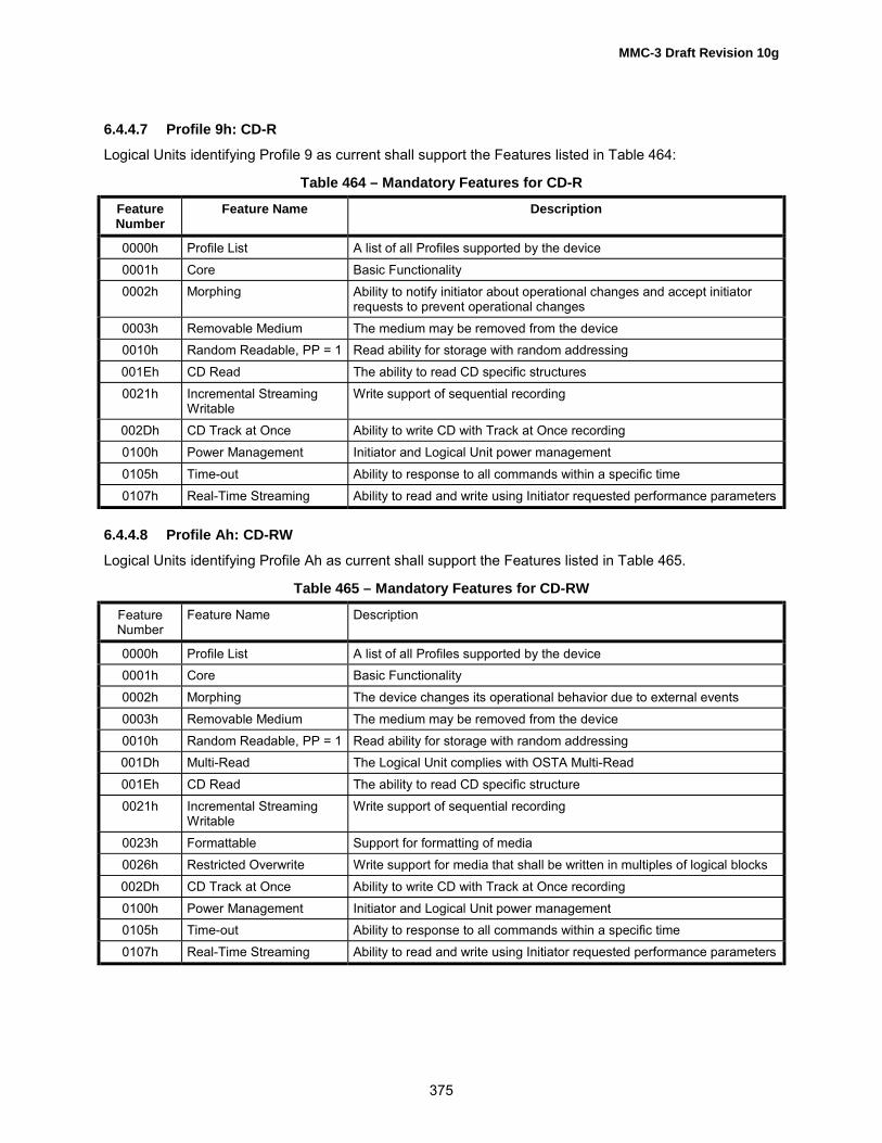
MMC-3 Draft Revision 10g
375
6.4.4.7 Profile 9h: CD-RLogical Units identifying Profile 9 as current shall support the Features listed in Table 464:
Table 464 – Mandatory Features for CD-R
FeatureNumber
Feature Name Description
0000h Profile List A list of all Profiles supported by the device0001h Core Basic Functionality0002h Morphing Ability to notify initiator about operational changes and accept initiator
requests to prevent operational changes0003h Removable Medium The medium may be removed from the device0010h Random Readable, PP = 1 Read ability for storage with random addressing001Eh CD Read The ability to read CD specific structures0021h Incremental Streaming
WritableWrite support of sequential recording
002Dh CD Track at Once Ability to write CD with Track at Once recording0100h Power Management Initiator and Logical Unit power management0105h Time-out Ability to response to all commands within a specific time0107h Real-Time Streaming Ability to read and write using Initiator requested performance parameters
6.4.4.8 Profile Ah: CD-RW
Logical Units identifying Profile Ah as current shall support the Features listed in Table 465.
Table 465 – Mandatory Features for CD-RW
FeatureNumber
Feature Name Description
0000h Profile List A list of all Profiles supported by the device0001h Core Basic Functionality0002h Morphing The device changes its operational behavior due to external events0003h Removable Medium The medium may be removed from the device0010h Random Readable, PP = 1 Read ability for storage with random addressing001Dh Multi-Read The Logical Unit complies with OSTA Multi-Read001Eh CD Read The ability to read CD specific structure0021h Incremental Streaming
WritableWrite support of sequential recording
0023h Formattable Support for formatting of media0026h Restricted Overwrite Write support for media that shall be written in multiples of logical blocks002Dh CD Track at Once Ability to write CD with Track at Once recording0100h Power Management Initiator and Logical Unit power management0105h Time-out Ability to response to all commands within a specific time0107h Real-Time Streaming Ability to read and write using Initiator requested performance parameters

MMC-3 Draft Revision 10g
376
6.4.4.9 Profile 10h: DVD-ROMLogical Units identifying Profile 10h as current shall support the Features listed in Table 466.
Table 466 – Mandatory Features for DVD-ROM
FeatureNumber
Feature Name Description
0000h Profile List A list of all Profiles supported by the device0001h Core Basic Functionality0002h Morphing The device changes its operational behavior due to external events0003h Removable Medium The medium may be removed from the device0010h Random Readable, PP=1 Read ability for storage devices with random addressing.001Fh DVD Read The ability to read DVD specific structures0100h Power Management Initiator and device directed power management0105h Timeout Ability to respond to all commands within a specific time0107h Real-Time Streaming Ability to read using Initiator requested performance parameters
6.4.4.10 Profile 11h: DVD-R Sequential recording
Logical Units identifying Profile 11h as current shall support the Features listed in Table 467:
Table 467 – Mandatory Features for DVD-R Sequential recording
FeatureNumber
Feature Name Description
0000h Profile List A list of all Profiles supported by the device0001h Core Basic Functionality0002h Morphing The device changes its operational behavior due to external events0003h Removable Medium The medium may be removed from the device0010h Random Readable, PP = 1 Read ability for storage with random addressing001Fh DVD Read The ability to respond to all commands within a specific time0021h Incremental Streaming
WritableWrite support for sequential recording
002Fh DVD-R/-RW Write Ability to write data in Disc At Once mode0100h Power Management Initiator and Logical Unit power management0105h Time-out Ability to response to all commands within a specific time0107h Real-Time Streaming Ability to read and write using initiator requested performance parameters0108h Logical Unit Serial Number Ability to provide Logical Unit serial number
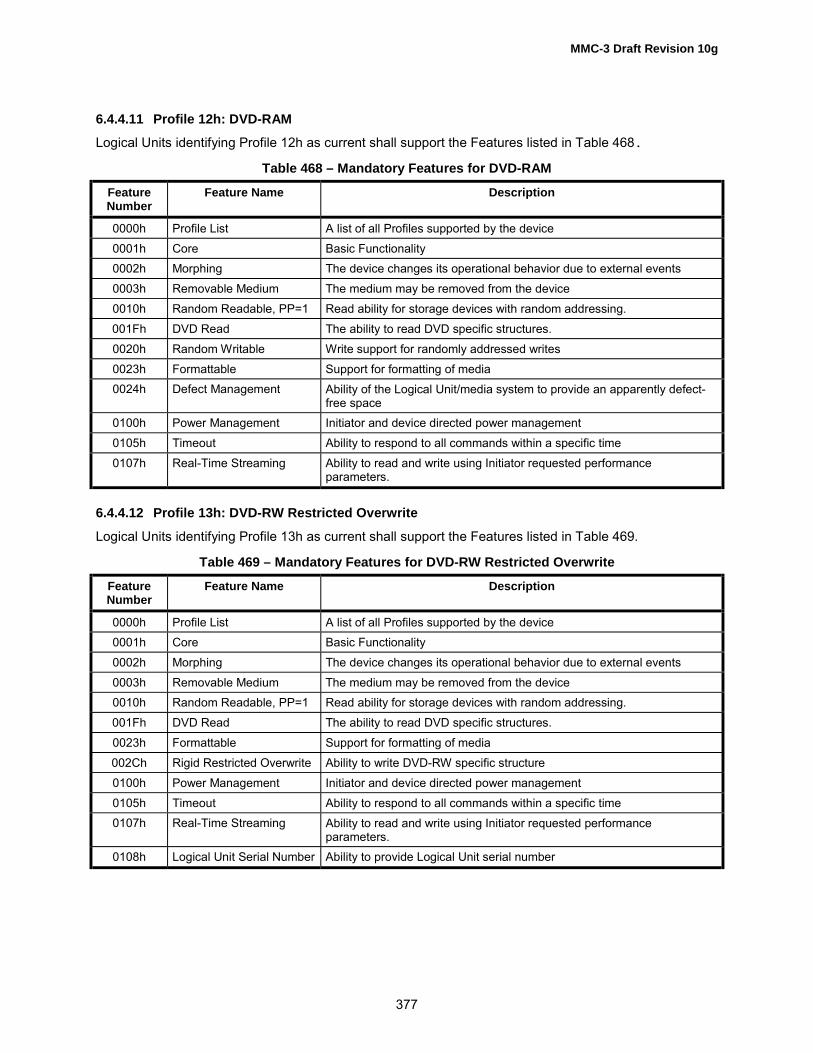
MMC-3 Draft Revision 10g
377
6.4.4.11 Profile 12h: DVD-RAMLogical Units identifying Profile 12h as current shall support the Features listed in Table 468.
Table 468 – Mandatory Features for DVD-RAM
FeatureNumber
Feature Name Description
0000h Profile List A list of all Profiles supported by the device0001h Core Basic Functionality0002h Morphing The device changes its operational behavior due to external events0003h Removable Medium The medium may be removed from the device0010h Random Readable, PP=1 Read ability for storage devices with random addressing.001Fh DVD Read The ability to read DVD specific structures.0020h Random Writable Write support for randomly addressed writes0023h Formattable Support for formatting of media0024h Defect Management Ability of the Logical Unit/media system to provide an apparently defect-
free space0100h Power Management Initiator and device directed power management0105h Timeout Ability to respond to all commands within a specific time0107h Real-Time Streaming Ability to read and write using Initiator requested performance
parameters.
6.4.4.12 Profile 13h: DVD-RW Restricted Overwrite
Logical Units identifying Profile 13h as current shall support the Features listed in Table 469.
Table 469 – Mandatory Features for DVD-RW Restricted Overwrite
FeatureNumber
Feature Name Description
0000h Profile List A list of all Profiles supported by the device0001h Core Basic Functionality0002h Morphing The device changes its operational behavior due to external events0003h Removable Medium The medium may be removed from the device0010h Random Readable, PP=1 Read ability for storage devices with random addressing.001Fh DVD Read The ability to read DVD specific structures.0023h Formattable Support for formatting of media002Ch Rigid Restricted Overwrite Ability to write DVD-RW specific structure0100h Power Management Initiator and device directed power management0105h Timeout Ability to respond to all commands within a specific time0107h Real-Time Streaming Ability to read and write using Initiator requested performance
parameters.0108h Logical Unit Serial Number Ability to provide Logical Unit serial number

MMC-3 Draft Revision 10g
378
6.4.4.13 Profile 14h: DVD-RW Sequential recordingLogical Units identifying Profile 14h as current shall support the Features listed in Table 467:
Table 470 – Mandatory Features for DVD-RW Sequential recording
FeatureNumber
Feature Name Description
0000h Profile List A list of all Profiles supported by the device0001h Core Basic Functionality0002h Morphing The device changes its operational behavior due to external events0003h Removable Medium The medium may be removed from the device0010h Random Readable, PP = 1 Read ability for storage with random addressing001Fh DVD Read The ability to respond to all commands within a specific time0021h Incremental Streaming
WritableWrite support for sequential recording
002Fh DVD-R/-RW Write Ability to write data in Disc At Once mode0100h Power Management Initiator and Logical Unit power management0105h Time-out Ability to response to all commands within a specific time0107h Real-Time Streaming Ability to read and write using initiator requested performance parameters0108h Logical Unit Serial Number Ability to provide Logical Unit serial number
6.4.4.14 Profile 1Ah: DVD+RWLogical Units identifying Profile 001Ah as current shall support the features listed in Table 471.
Table 471 – Mandatory Features for DVD+RW
FeatureNumber
Feature Name Description
0000h Profile List A list of all Profiles supported by the device0001h Core Mandatory behavior for all devices0002h Morphing The device changes its operational behavior due to external events0003h Removable Medium The medium may be removed from the device0010h Random Readable, PP=1 Read ability for storage devices with random addressing001Fh DVD Read The ability to read DVD specific structures0020h Random Writable Write support for randomly addressed writes0023h Formattable Support for formatting of media002Ah DVD+RW Support for reading and optionally writing DVD+RW Media0100h Power Management Host and device directed power management0105h Time-Out Ability to respond to all commands within a specific time0107h Real-time Streaming Ability to read and write using Host requested performance parameters010Ah DCBs The ability to read and optionally write DCBs.

MMC-3 Draft Revision 10g
379
6.4.4.15 Profile 20h: DDCD-ROMLogical Units identifying Profile 20h as current shall support the Features listed in Table 472.
Table 472 – Mandatory Feature List for the DDCD-ROM
FeatureNumber
Feature Name Description
0000h Profile List A list of all Profiles supported by the device0001h Core Basic Functionality0002h Morphing The device changes its operational behavior due to external events0003h Removable Medium The medium may be removed from the device0010h Random Readable, PP = 1 Read ability for storage with random addressing0030h DDCD Read The ability to read DDCD specific structure0100h Power Management Initiator and device directed power management.0105h Time-out Ability to response to all commands within a specific time
6.4.4.16 Profile 21h: DDCD-RLogical Units identifying Profile 20h as current shall support the Features listed in Table 473.
Table 473 – Mandatory Feature List for the DDCD-R
FeatureNumber
Feature Name Description
0000h Profile List A list of all Profiles supported by the device0001h Core Basic Functionality0002h Morphing The device changes its operational behavior due to external events0003h Removable Medium The medium may be removed from the device0010h Random Readable, PP = 1 Read ability for storage with random addressing0021h Incremental Streaming
WritableWrite support of sequential recording
0030h DDCD Read The ability to read DDCD specific structure0031h DDCD-R Write The ability to write DDCD-R specific structure0100h Power Management Initiator and Logical Unit power management.0105h Time-out Ability to response to all commands within a specific time0107h Real-Time Streaming Ability to read and write using Initiator requested performance parameters

MMC-3 Draft Revision 10g
380
6.4.4.17 Profile 22h: DDCD-RWLogical Units identifying Profile 20h as current shall support the Features listed in Table 474.
Table 474 – Mandatory Feature List for the DDCD-R/RW
FeatureNumber
Feature Name Description
0000h Profile List A list of all Profiles supported by the device0001h Core Basic Functionality0002h Morphing The device changes its operational behavior due to external events0003h Removable Medium The medium may be removed from the device0010h Random Readable, PP = 1 Read ability for storage with random addressing0020h Random Writable Write support for randomly addressed writes0021h Incremental Streaming
WritableWrite support of sequential recording
0023h Formattable Support for formatting of media0026h Restricted Overwrite Write support for media that shall be written in multiples of logical blocks0030h DDCD Read The ability to read DDCD specific structure0031h DDCD-R Write The ability to write DDCD-R specific structure0032h DDCD-RW Write The ability to write DDCD-RW specific structure0100h Power Management Initiator and Logical Unit power management.0105h Time-out Ability to response to all commands within a specific time0107h Real-Time Streaming Ability to read and write using Initiator requested performance parameters
6.4.4.18 Profile FFFFh: Logical Units Not Conforming to a Standard Profile
Logical Units identifying Profile FFFFh as current shall support the Features listed in Table 475.
Table 475 – Mandatory Features for Logical Units Not Conforming to a Standard Profile
FeatureNumber
Feature Name Description
0000h Profile List A list of all Profiles supported by the device0001h Core Basic Functionality

MMC-3 Draft Revision 10g
381
Annex A(Normative)
SK, ASC and ASCQ Combinations for MMCA.1 OverviewThis annex lists error codes that may be generated by MMC defined Logical Units. Specificcommands specify that certain errors occur in response to certain conditions, but each commanddoes not contain a comprehensive list of possible error conditions.
A.2 Deferred ErrorsAny error may be reported in response to any command due to the occurrence of a deferrederror. For example, a write error may occur due to a cached write command and that error shallbe reported in response to the next command.
A.3 Error ListsA number of tables are included within this annex for error classification. Each table has columnsidentifying SK, ASC, and ASCQ values and the associated meaning. Each command descriptionsub-clause contains an error-reporting table with entries that reference the tables included withinthis annex. There are five classifications:
Table A.1 � Logical Unit Sense Key, ASC and ASCQ Assignments, lists all errors.
Table A.2 � Logical Unit General Errors, lists errors that may occur at any time, typically inresponse to a protocol or hardware error or user intervention.
Table A.3 � Media Access Errors, lists errors that may be generated by media access commandsof any type (read of control or user data or writing of control or data area).
Table A.4 � Logical Unit Write Errors, describes errors that may be generated by commands thatcause user or control data to be written to the medium.
Table A.5 � Logical Unit Fixation Errors, describes errors that may be generated by commandsthat cause the Logical Unit session to be closed.

MMC-3 Draft Revision 10g
382
Table A.1 – Logical Unit Sense Key, ASC and ASCQ Assignments
Sense Key ASC ASCQ Description0 00 00 NO ADDITIONAL SENSE INFORMATION
B 00 06 I/O PROCESS TERMINATED
5 00 11 AUDIO PLAY OPERATION IN PROGRESS
5 00 12 AUDIO PLAY OPERATION PAUSED
5 00 13 AUDIO PLAY OPERATION SUCCESSFULLY COMPLETED
5 00 14 AUDIO PLAY OPERATION STOPPED DUE TO ERROR
5 00 15 NO CURRENT AUDIO STATUS TO RETURN
4 00 17 CLEANING REQUESTED
3 02 00 NO SEEK COMPLETE
2 04 00 LOGICAL UNIT NOT READY, CAUSE NOT REPORTABLE
2 04 01 LOGICAL UNIT IS IN PROCESS OF BECOMING READY
2 04 02 LOGICAL UNIT NOT READY, INITIALIZING CMD. REQUIRED
2 04 03 LOGICAL UNIT NOT READY, MANUAL INTERVENTION REQUIRED
2 04 04 LOGICAL UNIT NOT READY, FORMAT IN PROGRESS
2 04 07 LOGICAL UNIT NOT READY, OPERATION IN PROGRESS
2 04 08 LOGICAL UNIT NOT READY, LONG WRITE IN PROGRESS
4 05 00 LOGICAL UNIT DOES NOT RESPOND TO SELECTION
3 06 00 NO REFERENCE POSITION FOUND
5 07 00 MULTIPLE PERIPHERAL DEVICES SELECTED
4 08 00 LOGICAL UNIT COMMUNICATION FAILURE
4 08 01 LOGICAL UNIT COMMUNICATION TIME-OUT
4 08 02 LOGICAL UNIT COMMUNICATION PARITY ERROR
4 08 03 LOGICAL UNIT COMMUNICATION CRC ERROR (ULTRA-DMA/32)
4 09 00 TRACK FOLLOWING ERROR
4 09 01 TRACKING SERVO FAILURE
4 09 02 FOCUS SERVO FAILURE
4 09 03 SPINDLE SERVO FAILURE
4 09 04 HEAD SELECT FAULT
6 0A 00 ERROR LOG OVERFLOW
1 0B 00 WARNING
1 0B 01 WARNING - SPECIFIED TEMPERATURE EXCEEDED
1 0B 02 WARNING - ENCLOSURE DEGRADED
3 0C 00 WRITE ERROR
3 0C 07 WRITE ERROR - RECOVERY NEEDED
3 0C 08 WRITE ERROR - RECOVERY FAILED
3 0C 09 WRITE ERROR - LOSS OF STREAMING
3 0C 0A WRITE ERROR - PADDING BLOCKS ADDED
Notes:
1. All values are in hexadecimal2. When no value for SK is given, the error is applicable to multiple sense keys.

MMC-3 Draft Revision 10g
383
Table A.1 – Logical Unit Sense Key, ASC and ASCQ Assignments (cont.)
Sense Key ASC ASCQ Description3 11 00 UNRECOVERED READ ERROR
3 11 01 READ RETRIES EXHAUSTED
3 11 02 ERROR TOO LONG TO CORRECT
3 11 05 L-EC UNCORRECTABLE ERROR
3 11 06 CIRC UNRECOVERED ERROR
3 11 0F ERROR READING UPC/EAN NUMBER
3 11 10 ERROR READING ISRC NUMBER
B 11 11 READ ERROR - LOSS OF STREAMING
3 15 00 RANDOM POSITIONING ERROR
3 15 01 MECHANICAL POSITIONING ERROR
3 15 02 POSITIONING ERROR DETECTED BY READ OF MEDIUM
1 17 00 RECOVERED DATA WITH NO ERROR CORRECTION APPLIED
1 17 01 RECOVERED DATA WITH RETRIES
1 17 02 RECOVERED DATA WITH POSITIVE HEAD OFFSET
1 17 03 RECOVERED DATA WITH NEGATIVE HEAD OFFSET
1 17 04 RECOVERED DATA WITH RETRIES AND/OR CIRC APPLIED
1 17 05 RECOVERED DATA USING PREVIOUS SECTOR ID
1 17 07 RECOVERED DATA WITHOUT ECC - RECOMMEND REASSIGNMENT
1 17 08 RECOVERED DATA WITHOUT ECC - RECOMMEND REWRITE
1 17 09 RECOVERED DATA WITHOUT ECC - DATA REWRITTEN
1 18 00 RECOVERED DATA WITH ERROR CORRECTION APPLIED
1 18 01 RECOVERED DATA WITH ERROR CORR. & RETRIES APPLIED
1 18 02 RECOVERED DATA - DATA AUTO-REALLOCATED
1 18 03 RECOVERED DATA WITH CIRC
1 18 04 RECOVERED DATA WITH L-EC
1 18 05 RECOVERED DATA � RECOMMEND REASSIGNMENT
1 18 06 RECOVERED DATA � RECOMMEND REWRITE
1 18 08 RECOVERED DATA WITH LINKING
5 1A 00 PARAMETER LIST LENGTH ERROR
4 1B 00 SYNCHRONOUS DATA TRANSFER ERROR
A 1D 00 MISCOMPARE DURING VERIFY OPERATION
5 20 00 INVALID COMMAND OPERATION CODE
5 21 00 LOGICAL BLOCK ADDRESS OUT OF RANGE
5 21 01 INVALID ELEMENT ADDRESS
5 21 02 INVALID ADDRESS FOR WRITE
5 24 00 INVALID FIELD IN CDB
5 25 00 LOGICAL UNIT NOT SUPPORTED
Notes:
1. All values are in hexadecimal2. When no value for SK is given, the error is applicable to multiple sense keys.
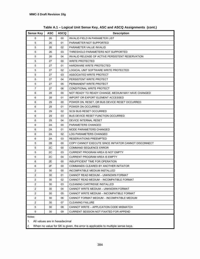
MMC-3 Draft Revision 10g
384
Table A.1 – Logical Unit Sense Key, ASC and ASCQ Assignments (cont.)
Sense Key ASC ASCQ Description5 26 00 INVALID FIELD IN PARAMETER LIST
5 26 01 PARAMETER NOT SUPPORTED
5 26 02 PARAMETER VALUE INVALID
5 26 03 THRESHOLD PARAMETERS NOT SUPPORTED
5 26 04 INVALID RELEASE OF ACTIVE PERSISTENT RESERVATION
5 27 00 WRITE PROTECTED
5 27 01 HARDWARE WRITE PROTECTED
5 27 02 LOGICAL UNIT SOFTWARE WRITE PROTECTED
5 27 03 ASSOCIATED WRITE PROTECT
5 27 04 PERSISTENT WRITE PROTECT
5 27 05 PERMANENT WRITE PROTECT
7 27 06 CONDITIONAL WRITE PROTECT
6 28 00 NOT READY TO READY CHANGE, MEDIUM MAY HAVE CHANGED
6 28 01 IMPORT OR EXPORT ELEMENT ACCESSED
6 29 00 POWER ON, RESET, OR BUS DEVICE RESET OCCURRED
6 29 01 POWER ON OCCURRED
6 29 02 SCSI BUS RESET OCCURRED
6 29 03 BUS DEVICE RESET FUNCTION OCCURRED
6 29 04 DEVICE INTERNAL RESET
6 2A 00 PARAMETERS CHANGED
6 2A 01 MODE PARAMETERS CHANGED
6 2A 02 LOG PARAMETERS CHANGED
6 2A 03 RESERVATIONS PREEMPTED
5 2B 00 COPY CANNOT EXECUTE SINCE INITIATOR CANNOT DISCONNECT
5 2C 00 COMMAND SEQUENCE ERROR
5 2C 03 CURRENT PROGRAM AREA IS NOT EMPTY
5 2C 04 CURRENT PROGRAM AREA IS EMPTY
6 2E 00 INSUFFICIENT TIME FOR OPERATION
6 2F 00 COMMANDS CLEARED BY ANOTHER INITIATOR
2 30 00 INCOMPATIBLE MEDIUM INSTALLED
2 30 01 CANNOT READ MEDIUM � UNKNOWN FORMAT
2 30 02 CANNOT READ MEDIUM � INCOMPATIBLE FORMAT
2 30 03 CLEANING CARTRIDGE INSTALLED
2 30 04 CANNOT WRITE MEDIUM � UNKNOWN FORMAT
2 30 05 CANNOT WRITE MEDIUM � INCOMPATIBLE FORMAT
2 30 06 CANNOT FORMAT MEDIUM � INCOMPATIBLE MEDIUM
2 30 07 CLEANING FAILURE
5 30 08 CANNOT WRITE � APPLICATION CODE MISMATCH
5 30 09 CURRENT SESSION NOT FIXATED FOR APPEND
Notes:
1. All values are in hexadecimal2. When no value for SK is given, the error is applicable to multiple sense keys.

MMC-3 Draft Revision 10g
385
Table A.1 – Logical Unit Sense Key, ASC and ASCQ Assignments (cont.)
Sense Key ASC ASCQ Description5 30 10 MEDIUM NOT FORMATTED
3 31 00 MEDIUM FORMAT CORRUPTED
3 31 01 FORMAT COMMAND FAILED
3 31 02 ZONED FORMATTING FAILED DUE TO SPARE LINKING
34 00 ENCLOSURE FAILURE
35 00 ENCLOSURE SERVICES FAILURE
35 01 UNSUPPORTED ENCLOSURE FUNCTION
35 02 ENCLOSURE SERVICES UNAVAILABLE
35 03 ENCLOSURE SERVICES TRANSFER FAILURE
35 04 ENCLOSURE SERVICES TRANSFER REFUSED
1 37 00 ROUNDED PARAMETER
5 39 00 SAVING PARAMETERS NOT SUPPORTED
2 3A 00 MEDIUM NOT PRESENT
2 3A 01 MEDIUM NOT PRESENT - TRAY CLOSED
2 3A 02 MEDIUM NOT PRESENT - TRAY OPEN
6 3B 0D MEDIUM DESTINATION ELEMENT FULL
6 3B 0E MEDIUM SOURCE ELEMENT EMPTY
6 3B 0F END OF MEDIUM REACHED
6 3B 11 MEDIUM MAGAZINE NOT ACCESSIBLE
6 3B 12 MEDIUM MAGAZINE REMOVED
6 3B 13 MEDIUM MAGAZINE INSERTED
6 3B 14 MEDIUM MAGAZINE LOCKED
6 3B 15 MEDIUM MAGAZINE UNLOCKED
4 3B 16 MECHANICAL POSITIONING OR CHANGER ERROR
5 3D 00 INVALID BITS IN IDENTIFY MESSAGE
2 3E 00 LOGICAL UNIT HAS NOT SELF-CONFIGURED YET
4 3E 01 LOGICAL UNIT FAILURE
4 3E 02 TIMEOUT ON LOGICAL UNIT
6 3F 00 TARGET OPERATING CONDITIONS HAVE CHANGED
6 3F 01 MICROCODE HAS BEEN CHANGED
6 3F 02 CHANGED OPERATING DEFINITION
6 3F 03 INQUIRY DATA HAS CHANGED
4 40 NN DIAGNOSTIC FAILURE ON COMPONENT NN (80H-FFH)
5 43 00 MESSAGE ERROR
4 44 00 INTERNAL TARGET FAILURE
B 45 00 SELECT OR RESELECT FAILURE
4 46 00 UNSUCCESSFUL SOFT RESET
4 47 00 SCSI PARITY ERROR
B 48 00 INITIATOR DETECTED ERROR MESSAGE RECEIVED
B 49 00 INVALID MESSAGE ERROR
Notes:
1. All values are in hexadecimal2. When no value for SK is given, the error is applicable to multiple sense keys.

MMC-3 Draft Revision 10g
386
Table A.1 – Logical Unit Sense Key, ASC and ASCQ Assignments (cont.)
Sense Key ASC ASCQ Description4 4A 00 COMMAND PHASE ERROR
4 4B 00 DATA PHASE ERROR
4 4C 00 LOGICAL UNIT FAILED SELF-CONFIGURATION
B 4D NN TAGGED OVERLAPPED COMMANDS (NN = QUEUE TAG)
B 4E 00 OVERLAPPED COMMANDS ATTEMPTED
3 51 00 ERASE FAILURE
3 51 01 ERASE FAILURE - INCOMPLETE ERASE OPERATION DETECTED4 53 00 MEDIA LOAD OR EJECT FAILED
5 53 02 MEDIUM REMOVAL PREVENTED
5 55 00 SYSTEM RESOURCE FAILURE
3 57 00 UNABLE TO RECOVER TABLE-OF-CONTENTS
6 5A 00 OPERATOR REQUEST OR STATE CHANGE INPUT
6 5A 01 OPERATOR MEDIUM REMOVAL REQUEST
6 5A 02 OPERATOR SELECTED WRITE PROTECT
6 5A 03 OPERATOR SELECTED WRITE PERMIT
6 5B 00 LOG EXCEPTION
6 5B 01 THRESHOLD CONDITION MET
6 5B 02 LOG COUNTER AT MAXIMUM
6 5B 03 LOG LIST CODES EXHAUSTED
1 5D 01 FAILURE PREDICTION THRESHOLD EXCEEDED � Predicted Media failure
1 5D 02 LOGICAL UNIT FAILURE PREDICTION THRESHOLD EXCEEDED
1 5D 03 FAILURE PREDICTION THRESHOLD EXCEEDED � Predicted Spare Area Exhaustion
1 5D FF FAILURE PREDICTION THRESHOLD EXCEEDED (FALSE)
6 5E 00 LOW POWER CONDITION ON
6 5E 01 IDLE CONDITION ACTIVATED BY TIMER
6 5E 02 STANDBY CONDITION ACTIVATED BY TIMER
6 5E 03 IDLE CONDITION ACTIVATED BY COMMAND
6 5E 04 STANDBY CONDITION ACTIVATED BY COMMAND
5 63 00 END OF USER AREA ENCOUNTERED ON THIS TRACK
5 63 01 PACKET DOES NOT FIT IN AVAILABLE SPACE
5 64 00 ILLEGAL MODE FOR THIS TRACK
5 64 01 INVALID PACKET SIZE
4 65 00 VOLTAGE FAULT
Notes:
1. All values are in hexadecimal2. When no value for SK is given, the error is applicable to multiple sense keys.

MMC-3 Draft Revision 10g
387
Table A.1 – Logical Unit Sense Key, ASC and ASCQ Assignments (cont.)
Sense Key ASC ASCQ Description5 6F 00 COPY PROTECTION KEY EXCHANGE FAILURE � AUTHENTICATION FAILURE
5 6F 01 COPY PROTECTION KEY EXCHANGE FAILURE � KEY NOT PRESENT
5 6F 02 COPY PROTECTION KEY EXCHANGE FAILURE �KEY NOT ESTABLISHED
5 6F 03 READ OF SCRAMBLED SECTOR WITHOUT AUTHENTICATION
5 6F 04 MEDIA REGION CODE IS MISMATCHED TO LOGICAL UNIT REGION
5 6F 05 LOGICAL UNIT REGION MUST BE PERMANENT/REGION RESET COUNT ERROR
3 72 00 SESSION FIXATION ERROR
3 72 01 SESSION FIXATION ERROR WRITING LEAD-IN
3 72 02 SESSION FIXATION ERROR WRITING LEAD-OUT
5 72 03 SESSION FIXATION ERROR � INCOMPLETE TRACK IN SESSION
5 72 04 EMPTY OR PARTIALLY WRITTEN RESERVED TRACK
5 72 05 NO MORE TRACK RESERVATIONS ALLOWED
3 73 00 CD CONTROL ERROR
1 73 01 POWER CALIBRATION AREA ALMOST FULL
3 73 02 POWER CALIBRATION AREA IS FULL
3 73 03 POWER CALIBRATION AREA ERROR
3 73 04 PROGRAM MEMORY AREA UPDATE FAILURE
3 73 05 PROGRAM MEMORY AREA IS FULL
3 73 06 RMA/PMA IS ALMOST FULL
Notes:
1. All values are in hexadecimal2. When no value for SK is given, the error is applicable to multiple sense keys.

MMC-3 Draft Revision 10g
388
Table A.2 – Logical Unit General Errors
Sense Key ASC ASCQ Description0 00 00 NO ADDITIONAL SENSE INFORMATION
B 00 06 I/O PROCESS TERMINATED
2 04 00 LOGICAL UNIT NOT READY, CAUSE NOT REPORTABLE
2 04 01 LOGICAL UNIT IS IN PROCESS OF BECOMING READY
2 04 02 LOGICAL UNIT NOT READY, INITIALIZING CMD. REQUIRED
2 04 03 LOGICAL UNIT NOT READY, MANUAL INTERVENTION REQUIRED
2 04 04 LOGICAL UNIT NOT READY, FORMAT IN PROGRESS
2 04 07 LOGICAL UNIT NOT READY, OPERATION IN PROGRESS
2 04 08 LOGICAL UNIT NOT READY, LONG WRITE IN PROGRESS
4 05 00 LOGICAL UNIT DOES NOT RESPOND TO SELECTION
5 07 00 MULTIPLE PERIPHERAL DEVICES SELECTED
4 08 00 LOGICAL UNIT COMMUNICATION FAILURE
4 08 01 LOGICAL UNIT COMMUNICATION TIME-OUT
4 08 02 LOGICAL UNIT COMMUNICATION PARITY ERROR
6 0A 00 ERROR LOG OVERFLOW
1 0B 00 WARNING
1 0B 01 WARNING - SPECIFIED TEMPERATURE EXCEEDED
1 0B 02 WARNING - ENCLOSURE DEGRADED
5 1A 00 PARAMETER LIST LENGTH ERROR
4 1B 00 SYNCHRONOUS DATA TRANSFER ERROR
5 20 00 INVALID COMMAND OPERATION CODE
5 24 00 INVALID FIELD IN CDB
5 25 00 LOGICAL UNIT NOT SUPPORTED
5 26 00 INVALID FIELD IN PARAMETER LIST
5 26 01 PARAMETER NOT SUPPORTED
5 26 02 PARAMETER VALUE INVALID
6 28 00 NOT READY TO READY CHANGE, MEDIUM MAY HAVE CHANGED
6 29 00 POWER ON, RESET, OR BUS DEVICE RESET OCCURRED
6 29 01 POWER ON OCCURRED
6 29 02 SCSI BUS RESET OCCURRED
6 29 03 BUS DEVICE RESET FUNCTION OCCURRED
6 29 04 DEVICE INTERNAL RESET
6 2A 00 PARAMETERS CHANGED
6 2A 01 MODE PARAMETERS CHANGED
6 2A 02 LOG PARAMETERS CHANGED
6 2F 00 COMMANDS CLEARED BY ANOTHER INITIATOR
Notes:
1. All values are in hexadecimal2. When no value for SK is given, the error is applicable to multiple sense keys.

MMC-3 Draft Revision 10g
389
Table A.2 – Logical Unit General Errors (cont.)
Sense Key ASC ASCQ Description34 00 ENCLOSURE FAILURE
35 00 ENCLOSURE SERVICES FAILURE
35 01 UNSUPPORTED ENCLOSURE FUNCTION
35 02 ENCLOSURE SERVICES UNAVAILABLE
35 03 ENCLOSURE SERVICES TRANSFER FAILURE
35 04 ENCLOSURE SERVICES TRANSFER REFUSED
5 3D 00 INVALID BITS IN IDENTIFY MESSAGE
2 3E 00 LOGICAL UNIT HAS NOT SELF-CONFIGURED YET
4 3E 01 LOGICAL UNIT FAILURE
4 3E 02 TIMEOUT ON LOGICAL UNIT
6 3F 00 TARGET OPERATING CONDITIONS HAVE CHANGED
6 3F 01 MICROCODE HAS BEEN CHANGED
6 3F 02 CHANGED OPERATING DEFINITION
6 3F 03 INQUIRY DATA HAS CHANGED
4 40 NN DIAGNOSTIC FAILURE ON COMPONENT NN (80H-FFH)
5 43 00 MESSAGE ERROR
4 44 00 INTERNAL TARGET FAILURE
B 45 00 SELECT OR RESELECT FAILURE
4 46 00 UNSUCCESSFUL SOFT RESET
4 47 00 SCSI PARITY ERROR
B 48 00 INITIATOR DETECTED ERROR MESSAGE RECEIVED
B 49 00 INVALID MESSAGE ERROR
4 4A 00 COMMAND PHASE ERROR
4 4B 00 DATA PHASE ERROR
4 4C 00 LOGICAL UNIT FAILED SELF-CONFIGURATION
B 4D NN TAGGED OVERLAPPED COMMANDS (NN = QUEUE TAG)
B 4E 00 OVERLAPPED COMMANDS ATTEMPTED
6 5A 00 OPERATOR REQUEST OR STATE CHANGE INPUT
6 5A 01 OPERATOR MEDIUM REMOVAL REQUEST
6 5B 00 LOG EXCEPTION
6 5B 01 THRESHOLD CONDITION MET
6 5B 02 LOG COUNTER AT MAXIMUM
6 5B 03 LOG LIST CODES EXHAUSTED
6 5D 00 FAILURE PREDICTION THRESHOLD EXCEEDED
6 5D FF FAILURE PREDICTION THRESHOLD EXCEEDED (FALSE)
4 65 00 VOLTAGE FAULT
Notes:
1. All values are in hexadecimal2. When no value for SK is given, the error is applicable to multiple sense keys.
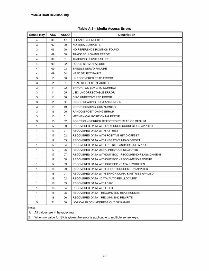
MMC-3 Draft Revision 10g
390
Table A.3 – Media Access Errors
Sense Key ASC ASCQ Description4 00 17 CLEANING REQUESTED
3 02 00 NO SEEK COMPLETE
3 06 00 NO REFERENCE POSITION FOUND
4 09 00 TRACK FOLLOWING ERROR
4 09 01 TRACKING SERVO FAILURE
4 09 02 FOCUS SERVO FAILURE
4 09 03 SPINDLE SERVO FAILURE
4 09 04 HEAD SELECT FAULT
3 11 00 UNRECOVERED READ ERROR
3 11 01 READ RETRIES EXHAUSTED
3 11 02 ERROR TOO LONG TO CORRECT
3 11 05 L-EC UNCORRECTABLE ERROR
3 11 06 CIRC UNRECOVERED ERROR
3 11 0F ERROR READING UPC/EAN NUMBER
3 11 10 ERROR READING ISRC NUMBER
3 15 00 RANDOM POSITIONING ERROR
3 15 01 MECHANICAL POSITIONING ERROR
3 15 02 POSITIONING ERROR DETECTED BY READ OF MEDIUM
1 17 00 RECOVERED DATA WITH NO ERROR CORRECTION APPLIED
1 17 01 RECOVERED DATA WITH RETRIES
1 17 02 RECOVERED DATA WITH POSITIVE HEAD OFFSET
1 17 03 RECOVERED DATA WITH NEGATIVE HEAD OFFSET
1 17 04 RECOVERED DATA WITH RETRIES AND/OR CIRC APPLIED
1 17 05 RECOVERED DATA USING PREVIOUS SECTOR ID
1 17 07 RECOVERED DATA WITHOUT ECC - RECOMMEND REASSIGNMENT
1 17 08 RECOVERED DATA WITHOUT ECC - RECOMMEND REWRITE
1 17 09 RECOVERED DATA WITHOUT ECC - DATA REWRITTEN
1 18 00 RECOVERED DATA WITH ERROR CORRECTION APPLIED
1 18 01 RECOVERED DATA WITH ERROR CORR. & RETRIES APPLIED
1 18 02 RECOVERED DATA - DATA AUTO-REALLOCATED
1 18 03 RECOVERED DATA WITH CIRC
1 18 04 RECOVERED DATA WITH L-EC
1 18 05 RECOVERED DATA � RECOMMEND REASSIGNMENT
1 18 06 RECOVERED DATA � RECOMMEND REWRITE
5 21 00 LOGICAL BLOCK ADDRESS OUT OF RANGE
Notes:
1. All values are in hexadecimal2. When no value for SK is given, the error is applicable to multiple sense keys.

MMC-3 Draft Revision 10g
391
Table A.3 – Media Access Errors (cont.)
Sense Key ASC ASCQ Description2 30 00 INCOMPATIBLE MEDIUM INSTALLED
2 30 01 CANNOT READ MEDIUM � UNKNOWN FORMAT
2 30 02 CANNOT READ MEDIUM � INCOMPATIBLE FORMAT
2 30 03 CLEANING CARTRIDGE INSTALLED
2 30 07 CLEANING FAILURE
3 31 00 MEDIUM FORMAT CORRUPTED
2 3A 00 MEDIUM NOT PRESENT
2 3A 01 MEDIUM NOT PRESENT - TRAY CLOSED
2 3A 02 MEDIUM NOT PRESENT - TRAY OPEN
3 57 00 UNABLE TO RECOVER TABLE-OF-CONTENTS
6 5E 00 LOW POWER CONDITION ON
6 5E 01 IDLE CONDITION ACTIVATED BY TIMER
6 5E 02 STANDBY CONDITION ACTIVATED BY TIMER
6 5E 03 IDLE CONDITION ACTIVATED BY COMMAND
6 5E 04 STANDBY CONDITION ACTIVATED BY COMMAND
5 63 00 END OF USER AREA ENCOUNTERED ON THIS TRACK
5 64 00 ILLEGAL MODE FOR THIS TRACK
3 73 00 CD CONTROL ERROR
Notes:
1. All values are in hexadecimal2. When no value for SK is given, the error is applicable to multiple sense keys.

MMC-3 Draft Revision 10g
392
Table A.4 – Logical Unit Write Errors
Sense Key ASC ASCQ Description3 0C 00 WRITE ERROR
3 0C 07 WRITE ERROR - RECOVERY NEEDED
3 0C 08 WRITE ERROR - RECOVERY FAILED
3 0C 09 WRITE ERROR - LOSS OF STREAMING
3 0C 0A WRITE ERROR - PADDING BLOCKS ADDED
5 27 00 WRITE PROTECTED
5 27 01 HARDWARE WRITE PROTECTED
5 27 02 LOGICAL UNIT SOFTWARE WRITE PROTECTED
5 27 03 ASSOCIATED WRITE PROTECT
5 27 04 PERSISTENT WRITE PROTECT
5 27 05 PERMANENT WRITE PROTECT
2 30 04 CANNOT WRITE MEDIUM � UNKNOWN FORMAT
2 30 05 CANNOT WRITE MEDIUM � INCOMPATIBLE FORMAT
5 30 08 CANNOT WRITE � APPLICATION CODE MISMATCH
5 30 09 CURRENT SESSION NOT FIXATED FOR APPEND
5 30 10 MEDIUM NOT FORMATTED
6 5A 02 OPERATOR SELECTED WRITE PROTECT
6 5A 03 OPERATOR SELECTED WRITE PERMIT
1 73 01 POWER CALIBRATION AREA ALMOST FULL
3 73 02 POWER CALIBRATION AREA IS FULL
3 73 03 POWER CALIBRATION AREA ERROR
3 73 04 PROGRAM MEMORY AREA UPDATE FAILURE
3 73 05 PROGRAM MEMORY AREA IS FULL
Notes:
1. All values are in hexadecimal2. When no value for SK is given, the error is applicable to multiple sense keys.
Table A.5 – Logical Unit Fixation Errors
Sense Key ASC ASCQ Description5 2C 03 CURRENT PROGRAM AREA IS NOT EMPTY
5 2C 04 CURRENT PROGRAM AREA IS EMPTY
3 72 00 SESSION FIXATION ERROR
3 72 01 SESSION FIXATION ERROR WRITING LEAD-IN
3 72 02 SESSION FIXATION ERROR WRITING LEAD-OUT
5 72 03 SESSION FIXATION ERROR � INCOMPLETE TRACK IN SESSION
5 72 04 EMPTY OR PARTIALLY WRITTEN RESERVED TRACK
Notes:
1. All values are in hexadecimal2. When no value for SK is given, the error is applicable to multiple sense keys.

MMC-3 Draft Revision 10g
393
Annex B(normative)
ATAPI ComplianceB.1 IntroductionThis section describes the implementation of the MultiMedia Commands in ATAPI devices. Theintent is to make the command sets highly compatible. It may be desired that a common devicedriver exist to control both SCSI and ATAPI devices.
B.2 GeneralATAPI devices implement a subset of SCSI behavior. Certain errors and conditions that exist inSCSI do not exist in ATAPI. In addition, certain terms are used in ATAPI instead of related SCSIterms. The mechanisms for transporting the commands, data, and status are unique to eachtransport. Addressing of units is also unique to each transport. MMC-3 does not directly specifyany of these mechanisms; the command and data layer definition may be layered on eithertransport.
B.2.1 Terms
B.2.1.1 Initiatorthe ATAPI equivalent for the SCSI term �Initiator.�
B.2.1.2 Device
the ATAPI equivalent for the SCSI term �Target� or �Logical Unit.�
B.2.1.3 Command Packet
the ATAPI equivalent for the SCSI term �Command Descriptor Block.�
B.2.2 Supported Block SizesATAPI does not use the block size in the mode select block descriptor. Instead, the block sizeshall be determined by the command. The READ Command shall return 2 048 bytes per block.The WRITE command shall send the number of bytes per block as determined by the WriteParameters Page. The READ CD and READ CD MSF commands shall return the number ofbytes per block as specified by the command.
B.2.3 CD Audio error reportingPLAY AUDIO Commands with the immediate bit set in the audio control mode return status assoon as the command has been validated (that may involve a seek to the starting address). Theplayback operation continues and may complete without notification to the Initiator. Errortermination of audio operations shall not be reported to the Initiator by returning immediateCHECK CONDITION status to the next command. The status may be obtained with READ SUB-CHANNEL or any command that returns the audio status.
B.2.4 Multi-Initiator EnvironmentA multi-Initiator environment cannot exist in ATAPI. Therefore, conditions that occur only in multi-Initiator environments cannot occur. For example, there is no way in ATAPI to produce areservation conflict, or for another Initiator to change common mode parameters. Thedescriptions of these conditions in SCSI shall be ignored in ATAPI implementations.

MMC-3 Draft Revision 10g
394
B.2.5 Command Packet PaddingAll ATAPI commands are twelve bytes long. SCSI commands are six, ten, or twelve bytes long.To build the appropriate ATAPI Command Packet, padding bytes shall be added to the six andten byte SCSI Command Descriptor Blocks. Six byte commands shall have six padding bytesadded. Ten byte commands shall have two padding bytes added. These pad bytes shall have avalue of zero.The Control byte shall be reserved and set to zero.
B.2.6 Mapping of reset functions shows how the different reset functions specified in the SCSI standards are used in thisstandard. Note that this table is not intended to show all possible resets or their mapping.
Table B.1 – Example Reset Function Mapping in ATAPI
Reset Type ATAPI
Power-On Reset Same as Power-On ResetHard Reset
Hard ResetATA SRST. This is a channel reset and assuch is treated as a Hard Reset. Howeverthe SRST shall not reset any modeparameters to the default state.
Device Reset Device Reset in ATA/ATAPI-4

MMC-3 Draft Revision 10g
395
Annex C(normative)
Requirements for SBP-2 ComplianceC.1 SBP-2 Definitions
C.1.1 command blockSpace reserved within an ORB to describe a command intended for a Logical Unit that controlsdevice functions or the transfer of data to or from device medium.
C.1.2 IEEE 1394shall be understood as a reference to IEEE Std 1394-1995 as amended by IEEE Std 1394a-2000
C.1.3 loginThe process by which an Initiator obtains access to a set of device fetch agents. The device fetchagents and their control and status registers provide a mechanism for an Initiator to signal ORB�sto the device.
C.1.4 quadletFour bytes, or 32 bits, of data.
C.1.5 registerA term used to describe quadlet aligned addresses that may be read or written by IEEE 1394transactions. In the context of this standard, the use of the term register does not imply a specifichardware implementation. For example, a processor may emulate the behavior of registers.
C.1.6 status blockA data structure written to system memory by a device when an operation request block has beencompleted.
C.1.7 system memoryThe portions of any node�s memory that are directly addressable by a IEEE 1394 address andwhich accepts, at a minimum, quadlet read and write access. Computers are the most commonexample of nodes that make system memory addressable from IEEE 1394, but any node,including those usually thought of as peripheral devices, may have system memory.
C.1.8 transactionAn exchange between a requester and a responder that consists of a request and a responsesub-action. The request sub-action transmits a IEEE 1394 transaction such as quadlet read,block write or lock, from the requesting node to the node intended to respond. Some IEEE 1394commands include data as well as transaction codes. The response sub-action returnscompletion status and sometimes data from the responding node to the requesting node.
C.1.9 unitA component of a IEEE 1394 node that provides processing, memory, I/O or some otherfunctionality. Once the node is initialized, the unit provides a CSR interface that is typicallyaccessed by device driver software at an Initiator. A node may have multiple units, whichnormally operate independently of each other. Within this standard, a unit is equivalent to adevice.

MMC-3 Draft Revision 10g
396
C.1.10 unit architectureThe specification of the interface to and the services provided by a unit implemented within anIEEE 1394 node.
C.1.11 unit attentionA state that a Logical Unit maintains while it has unsolicited status information to report to one ormore logged-in Initiators. A unit attention condition shall be created as described elsewhere inthis standard or in the applicable command set- and device-dependent documents.
C.2 SBP-2 Storage ModelThe SBP-2 Storage Model describes general characteristics and functions of MMC3 Logical Unitswhen implemented using SBP-2. It is intended to provide design information and lead to a betterunderstanding of MMC3 Logical Unit functionality.
C.2.1 Model configurationThis configuration is used only as an example of a common implementation. The followingassumptions are made for this model configuration.
• The device supports a single Logical Unit.
• The device does not support multiple Initiators.
• The device does not support isochronous data transfers.
Figure C.1 – Mass storage interface block diagram
C.2.2 Model operationThe block diagram in Figure C.1 indicates the functional blocks contained in an MMC3 device thatsupports SBP-2. This section describes the function of those blocks when processing a list ofORBs. The ORBs contain READ commands in this example.
1394 Bus 1394CSRs
ExecutionEngine
DeviceInterface
1394Interface
CommandAgentEngine
ManagementAgentEngine
1394Configuration
ROM

MMC-3 Draft Revision 10g
397
After power-on or bus reset, the Command_Agent and Management_Agent engines are in theReset state.The Initiator reads the MMC3 device�s Configuration ROM data in order to determine its 1394capabilities, SBP-2 capabilities, EUI-64 value, command set identifiers, software versions, andManagement_Agent CSR address.The Initiator performs a Login operation prior to any request to the MMC2 device. To perform aLogin, the Initiator writes its Login ORB address to the Management_Agent register. The LoginORB should contain either the current or master password for the Login to be successful. TheMMC3 device returns the Login response to the bus address specified in the Login ORB. Onefield of the Login response contains the Command_Agent�s CSR base address.Prior to initiating command transfers, the Initiator builds a list of Command_Block ORBs in systemmemory. The list may be as short as one ORB, but this example assumes a list length of morethan one. The last ORB in the list contains a NULL Next_ORB pointer which indicates the end ofthe list to the MMC3 device�s Command_Agent fetch engine.To transition the Command_Agent state from Reset to Active the Initiator writes the offset of thefirst ORB in the ORB list to the MMC3 device�s ORB_Pointer CSR address. This allows theCommand_Agent fetch engine to begin fetching ORBs from Initiator memory. If the Initiator writesto the Doorbell CSR, the MMC3 device shall ignore the Doorbell at this time.The MMC3 device fetches ORBs until its ORB space is full or until an ORB containing a NULLNext_ORB pointer is fetched. Fetched ORBs are routed to the Execution engine. The Executionengine may reorder the commands contained in the ORBs for best performance.As each READ command is executed the MMC3 device transfers READ data to the Initiator�smemory space via block write requests.Following the data transfer portion of each command the MMC3 device writes a Status_Block tothe Initiator�s Status_FIFO address. The Status_FIFO address for Command Block ORBs iscontained in the Login ORB. The status block contains SBP-2 specific command information,such as the ORB_offset of the Command_Block ORB associated with this status, as well asgeneral sense information.Note: ORBs contain a NOTIFY bit that is to be set if a Status_Block is to be written to Initiatormemory after every ORB is executed or cleared if a Status_Block is to be written only after ORBexecution encounters an error. This bit is advisory only. MMC3 Logical Units shall return aStatus_Block for all ORBs executed.If an ORB containing a Null Next_ORB pointer is fetched the Execution engine completes allfetched commands, including the one in the just fetched ORB, before the Command_Agenttransitions to the Suspended state.If additional commands are to be executed, the Initiator creates a new list of Command_BlockORBs; changes the Next_ORB pointer in the last ORB of the old list from NULL to the offset ofthe first ORB in the new list; then writes to the MMC3 device�s Doorbell CSR address. Thistransitions the Command_Agent to the Active state.The MMC3 device fetches the new Next_ORB pointer value from the last ORB of the old list andbegins fetching ORBS from the new list at that offset.If the Command_Agent fetch engine has not reached the ORB containing a Null Next_ORBpointer (and is still in the Active state), the MMC3 device ignores any writes to the Doorbell CSRaddress.This sequence may continue until the MMC3 device is reset, power is removed, or an erroroccurs.

MMC-3 Draft Revision 10g
398
C.2.3 Reconnect /Power reset support (normative)MMC3 Logical Units shall support the Reconnect management function following a bus reset, asdescribed in SBP-2. However, in the case that a Reconnect request occurs following a powerreset, MMC3 Logical Units shall perform as follows:1. Following a power reset, any previous login information shall be discarded and the device
shall transition to the Reset state.2. If an Initiator sends a Reconnect ORB to the device, the device shall return status with RESP
set to 0, REQUEST COMPLETE, and sbp_status set to A16, LOGIN ID NOT RECOGNIZED.
C.3 Configuration ROM support (normative)Although most Configuration ROM entries are generic, several contain information that is specificto each device type. Hard disk Logical Unit specific Configuration ROM information is defined inthis section.
C.3.1 Unit Directory - Command_Set_Spec_IDThe COMMAND_SET_SPEC_ID entry (key - 3816) is an immediate entry that specifies theorganization responsible for the command set definition for the device. SCSI targets shall have acommand_set_spec_ID of 00 609Eh, which indicates that NCITS is responsible for the commandset definition.
C.3.2 Unit Directory - Command_SetThe COMMAND_SET entry (key � 39h) is an immediate entry that, in combination with theCOMMAND_SET_SPEC_ID entry specifies the command set supported by the unit. SCSI targetsshall have a command_set value of 01 04D8h, which indicates that the target�s command set isspecified by SCSI Primary Commands 2 (SPC-2) and related command set standard(s), asdetermined by the targets peripheral device type(s).
C.3.3 Unit Directory - Command_Set_RevisionThe COMMAND_SET_REVISION entry (key - 3Bh) is an immediate entry that specifies the currentrevision level of the command set implemented by the unit.
C.3.4 Unit Directory - Logical_Unit_NumberThe LOGICAL_UNIT_NUMBER entry (key � 14h) is an immediate entry that specifies the device typeand the Logical Unit number of a Logical Unit supported by the device. The format of this entry isdefined in SBP-2 and duplicated here with additional field information for hard disk drives.
R in the figure above indicates reserved bits.
Logical_unit_number14h R O device_type(05h)
38h
39h
3Bh Command_set_revision
Command_set = 01
Command_set_spec_ID = 00

MMC-3 Draft Revision 10g
399
The ordered bit (abbreviated as O in the figure above) specifies the manner in which the LogicalUnit executes tasks signaled to the command block agent. If the Logical Unit executes andreports completion status without any ordering constraints, the ordered bit shall be zero.Otherwise, if the Logical Unit both executes all tasks in order and reports their completion statusin the same order, the ordered bit shall be one.The Device_Type field indicates the peripheral device type implemented by the Logical Unit. Thevalue defined for MMC3 Logical Units is 05h.Logical_Unit_Number field shall identify the Logical Unit to which the information in theLOGICAL_UNIT_NUMBER entry applies.
C.4 Login support (normative)MMC3 Logical Units shall implement the Login support as defined in SBP-2.
C.5 Security support (normative)MMC3 Logical Units shall implement security against unauthorized media access as defined inthe security annex of SBP-2.The master password, referenced in SBP-2, is contained in the INQUIRY command, Vital ProductData, page 80h. Following a successful Login operation, the Initiator shall request that the LogicalUnit perform the INQUIRY command, in order to obtain the Logical Unit�s serial number.
C.6 Status block support (normative)The status block for MMC3 Logical Units shall be implemented as described in the following textand figure. Refer to SBP-2, Annex B, for a complete description of all bits and fields.If no exception status is generated, only the first two quadlets (LEN =1) shall be written to theInitiator�s STATUS_FIFO address.If exception status is generated, the device shall write, at a minimum, the four quadlets (len = 2 )shown below. This format is required for unsolicited status as well as command status.
C.7 Unsolicited Status support (normative)MMC3 Logical Units that support the SBP-2 transport protocol shall implement the generation ofunsolicited status. Devices shall notify Initiators of unsolicited status support by setting theASYNCHRONOUS EVENT REPORTING CAPABILITY (AERC) bit to one in the standard data format of theINQUIRY command (see SPC-2)As stated in SBP-2, unsolicited status is enabled when the Initiator writes to theUnsolicited_Status_Enable CSR. Devices default to unsolicited status disabled and only sendunsolicited status following a write to the Unsolicited_Status_Enable CSR. TheUnsolicited_Status_Enable CSR is a handshake mechanism and shall be written after everyunsolicited status event in order to enable another such event.
information
sense qualifier
ORB-offset_hi sbp_statussrc
sfmt
resp
status v
d len
ORB_offset_lo
sense codesense keym e i

MMC-3 Draft Revision 10g
400
C.8 Unit attention conditionA unit attention condition shall persist for a logged-in Initiator untila) unsolicited status, that reports the unit attention condition, is successfully written to the
Initiator�s status FIFO address, orb) the Initiator�s login becomes invalid or is released. Logical Units may queue unit attention
conditions; more than one unit attention condition may exist at the same time.

MMC-3 Draft Revision 10g
401
Annex D (normative)
Requirements for Fibre Channel Protocol for SCSI ComplianceD.1 IntroductionThis Annex describes the implementation of the MultiMedia Commands in Fibre Channel devices.The intent is to highlight the concerns of implementation of the command set using the FibreChannel Protocol (FCP). The Fibre Channel Protocol for SCSI (ANSI Standard X3.269:1996) wasreferenced for the writing of this Annex.
D.2 GeneralCertain terms are used in FCP in addition to the related SCSI terms. The mechanisms fortransporting the commands, data, and status are unique to each transport. FCP differs from othertransports such as SBP-2, SCSI, etc. Addressing of units is also unique to each transport. MMCdoes not directly specify any of these mechanisms; the command and data layer definition maybe layered on either transport.
D.2.1 Terms
D.2.1.1 Originatorthe FCP equivalent for the SCSI term �Initiator.�
D.2.1.2 Responder
the FCP equivalent for the SCSI term �Target� or �Logical Unit.�
D.2.1.3 Information Unit (IU)
similar to the SCSI phases. Carried in FCP frames.
D.2.2 Information UnitsCDBs are transferred from the initiator to target using FCP_CMND IUs. Responses to thesecommands are returned in the FCP_RSP IUs. For write operations, a CDB and associated datamay be transferred in a single IU possibly followed by subsequent FCP_DATA IUs. For readoperations, the final IU may contain both the FCP_DATA and FCP_RSP.
D.2.3 Process login/logoutBefore any commands can be issued, the FCP link-level protocol of Process login (PRLI) shall becompleted between the initiator and target. This can be accomplished either implicitly via externalconventions or explicitly using IUs. The first command that completes after a PRLI shall generatea Unit Attention condition with an ASC of Reset Occurred (ASC=29h, ASCQ=00h).
D.2.4 Sense InformationFCP devices always use auto-sense to report the sense data associated with a CHECKCONDITION status in an FCP_RSP_IU. This replaces the most common but not the only use ofthe REQUEST SENSE command.
D.2.5 Reset MappingFCP initiators use the FCP_CNTL field contained within the FCP_CMND IU to reset the FCPtargets. Byte 2, bit 5 of the FCP_CNTL field represents a TARGET RESET that shall be mappedto a Hard Reset for MMC-2 targets. Byte 2, bit 2 of the FCP_CNTL field represents a CLEAR

MMC-3 Draft Revision 10g
402
TASK SET that shall be mapped to a Device Reset for MMC-2 targets. Byte 2, bit 1 of theFCP_CNTL field represents an ABORT TASK SET that shall be mapped to a Device Reset forMMC-2 targets.

MMC-3 Draft Revision 10g
403
Annex E(normative)
SPI (SCSI Parallel Interface) Implementation NotesE.1 IntroductionThis standard is intended to be used in conjunction with the SCSI Architecture Model (SAM), theSCSI Primary Command Set (SPC-2) standard, and the SCSI Block Command Set (SBC)standard. See the NCITS/T10 SCSI Standards for information on the physical connection andprotocol to be used for attachment of a SCSI Logical Unit.
E.2 SCSI Signal Utilization Logical Unit shall utilize the same signals and timing from the SCSI Standard and Extensions.
E.3 SCSI Compatibility
E.3.1 Additions to the SCSI StandardNew requirements:
• GET EVENT/STATUS NOTIFICATION command in addition to the AEN capability in SCSI.
• Features are introduced and added.
• CHANGE DEFINITION is not required.
• The Mechanism State in this specification uses a value of 3h for the data port in use and not1h as is specified in the SCSI Standard.
• The power model for this specification is different from that described for SCSI.
• The Information Exceptions Mode Page is called the Fault / Failure Reporting page in thisstandard.
E.4 Reset FunctionalityThis sub-clause describes the functionality of the various resets implemented in SCSI.
E.4.1 Power On ResetThe Power On Reset is an event that causes the Power On condition in SCSI. See �Task andCommand Lifetimes� in the SCSI Architecture Model standard (SAM).
E.4.2 Hard ResetHard Reset is described in the SCSI Architecture Model. See �Hard Reset� in SAM.A Hard Reset for a SCSI Device shall:� Abort all tasks in all task sets;� Clear all auto contingent allegiance conditions;� Release all SCSI device reservations;� Return any device operating modes to their appropriate initial conditions, similar to thoseconditions that would be found following device power-on. The MODE SELECT conditions shallbe restored to their last saved values if saved values have been established. MODE SELECTconditions for which no saved values, have been established, shall be returned to their defaultvalues;� Unit Attention condition shall be set.

MMC-3 Draft Revision 10g
404
E.4.3 TARGET RESET task management functionThe TARGET RESET function may be used to reset all Logical Units in the Target.Note: TheTARGET RESET task management function was called a �Bus Device Reset� in SCSI-2.If the Initiator issues the LOGICAL UNIT RESET function to a Logical Unit, the response of theLogical Unit shall be the same as the response to a TARGET RESET task management function.
E.4.4 Device ResetThere are two possible Device Reset alternatives, ABORT TASK SET and CLEAR TASK SET.The ABORT TASK SET is mandatory for all SCSI Logical Units. SCSI Logical Units that do notsupport tagged tasks may support CLEAR TASK SET.CLEAR TASK SET is different from ABORT TASK SET in that CLEAR TASK SET clears all of thequeued tasks for all Initiators. If the Logical Unit is in a single Initiator environment, ABORT andCLEAR TASK SET functions in the same manner.The ABORT/CLEAR TASK SET:� Does not immediately reset SCSI bus protocol.� Does not reset parameters in mode page to default values� Always keep the disc information such as disc TOC information� Does not change the Persistent Prevent state
E.4.5 Power Management and Device Reset in SCSIWhen a SCSI Device is in the Power Managed Sleep state, a reset through the service deliverysubsystem shall be used to wake the device.
E.4.6 Mapping of reset functionsError! Reference source not found. shows how the different reset functions specified in thevarious ATAPI specifications are used in this standard. Note that this table is not intended toshow all possible resets or their mapping.
Table E.1 – Example Reset Function Mapping in SCSI
Reset Type SCSIPower-On Reset Same as Power-On Reset
TARGET RESET task management functionHard Reset SAM Reset events. Note that this is SCSI
protocol dependent.SPI Reset Signal
Device Reset TARGET RESET

MMC-3 Draft Revision 10g
405
Annex F(normative)
Power Management FunctionsF.1 Power Management StatesFour power states are defined. These are named Active, Idle, Standby, and Sleep with Activebeing the �Full-On� state, Sleep the �Off� state and �Idle, Standby and Sleep� progressively moreaggressive power managed states. This model differs significantly from previous ATA and SCSIpower management definitions. This new model (Table F.1) defines power states in terms of theperceived impact on the end user, instead of absolute power levels. The Idle state is optimizedfor minimal end user performance impact. The Standby state is optimized for power savings.To provide consistent behavior across Logical Units, standard definitions are used for the powerstates of Logical Units. These states are defined in terms of the following criteria.- Power Consumption: How much power the Logical Unit uses.- Logical Unit Context: How much of the internal state of the Logical Unit is retained by hardwareand what shall be restored by the responsible software.- Restore time: How long it takes to raise the power level to the active power state and to put theLogical Unit into operational condition (including mechanical operation such as spin up) requiredbefore entering into the Active power state. Restoring is vendor specific and any mechanism canbe employed here to raise the power consumption and to put the Logical Unit in operationcondition required in a higher power state. For example, �turning on or raising internal Vcc forpower hungry circuits such as motors, laser sensors,� �raising internal Vcc or the clock frequencyfor the digital circuits,� etc. A critical factor is how quickly restoring the Logical Unit to operationcondition required in a higher power state (e.g. spin up).- De-power time: How long it takes to reduce the power to the desired level in lower power stateafter entering the lower power state from higher power state. De-powering is vendor specific andany mechanism can be employed here to reduce the power consumption. For example, �turningoff or lowering internal Vcc for power hungry circuits such as motors, laser sensors,� �loweringinternal Vcc or reducing the clock frequency for the digital circuits,� �dynamic clock gating,��cutting off the DC paths for unused circuits,� �turning off PLLs,� etc.
Table F.1 – Power Management Model States
Logical UnitState
PowerConsumption
Logical Unit ContextRetained
Restore Time
Active (D0) As needed foroperation
All None
Idle (D1) Less thanActive
All The Logical Unit shall be restored to activestate within 1 second on any request to enteractive state, independent of the de-poweringprocess.
Standby (D2) Less than idle All buffers are emptybefore enteringStandby state.
Vendor specific: Greater than or equal to Idleto Active
Sleep (D3) Less thanStandby
None, Buffer & All ofcommand queues areempty before enteringSleep state.
Greater than or equal to Standby to Active.Vendor Specific. May Need full initialization.The Initiator may remove Vcc.

MMC-3 Draft Revision 10g
406
Transitions between these power states may occur at the request of the Initiator or the LogicalUnit. Transitions to a higher power state from a lower power state shall occur after restoring theLogical Unit to the operating conditions (including mechanical operation if applicable, such asspin up) required in the higher power state. When the Logical Unit transitions from a higher powerstate to a lower power state, the Logical Unit shall be considered to be in the lower power statewhen the Logical Unit is assured of reaching the lower power condition. Actual de-poweringoccurs after the Logical Unit enters the lower power state. The Logical Unit shall generate apower event when the Logical Unit is considered to have entered a power state.In order to create a robust power management environment, Logical Units shall support thefollowing:- Four power states: Active(D0), Idle(D1), Standby(D2) and Sleep(D3).- Idle Timer. Provides a method for the Logical Unit to enter Idle state from Active state, followinga programmed period of inactivity.- Standby Timer. Provides a method for the Logical Unit to enter Standby state from either Activeor Idle state, following a programmed period of inactivity.- START STOP UNIT command and the Power Condition Field. Provides a method for theInitiator to request the Logical Unit to enter a power state.- GET EVENT/STATUS NOTIFICATION command. Notifies the Initiator of power state changesand current power status.- Power Condition Mode page. Enables or disables timers and specifies the reload value of theIdle and Standby timers.
F.2 Power State TransitionsActive State (D0):The Logical Unit is completely active and responsive. The Logical Unit is consuming its highestlevel of power. During the execution of a media access command (commands that reload bothtimers) the Logical Unit shall be in active state.The Logical Unit should minimize power consumption at all times, even when in the active state.Any mechanism can be employed, as long as it is transparent to software and does not preventthe Logical Unit from performing expected functions.For example, the Logical Unit may dynamically gate on/off internal clocks by monitoring busactivities and internal activities.Idle State (D1):In Idle state, the Logical Unit is capable of responding to commands but may take up to onesecond longer to complete commands than the Active state. The Logical Unit is consuming lesspower than the Active state. Any mechanism can be employed as long as the restoring time isless than one second. The Logical Unit may, for example:- Reduce internal clock frequency- Lower the internal Vcc for digital circuits- Dynamically gate internal clocks by monitoring bus/internal activitiesStandby State (D2):In Standby state the Logical Unit shall only be required to accept commands from the Initiator. Allother mechanisms are in the power save condition. In Standby state, the Logical Unit is capableof responding to commands but the Logical Unit takes longer to complete commands than whenin Idle state. Buffers shall be emptied before entering into Standby state. The Logical Unit contextshall be preserved. The Logical Unit is consuming less power than when in Idle state.

MMC-3 Draft Revision 10g
407
Sleep State (D3):Maximum power saving state. Buffers and all command queues, including GET EVENT/STATUSNOTIFICATION commands, shall be emptied before entering into the Sleep state. When theLogical Unit enters the sleep state, any GET EVENT/STATUS NOTIFICATION commandspresent in the command queue, shall be removed from the command queue, without commandcompletion. In this Sleep state, all functions are stopped and no commands, except for reset canbe received. The unit is consuming less power than when in the Standby state. The Logical Unitcontext is invalid in the Sleep state.The Initiator software shall fully initialize the Logical Unit after exiting Sleep state, as all contextmay be lost in the Sleep state. Therefore, disc(s)/cassette may be manually ejected or insertedwhile in sleep state, independent of any lock/unlock mechanism employed. For the Initiator toconsistently rely on the Logical Unit Media Status Notifications, when the Logical Unit is unable todetermine if media has been changed while the Logical Unit was in the sleep state, the LogicalUnit shall report NEW MEDIA on the next GET EVENT/STATUS NOTIFICATION (Media Status)command.In the Sleep state, the Initiator may completely remove power from the device by turning off Vcc.
F.3 Power Management State DiagramThe state diagram, Figure F.1, defines state transitions for the power management model.A power-on or hard reset always returns the Power State to the Standby State. A Device Resetdoes not alter the current Power State, unless the current Power State is Sleep. A Device Resetreceived while in sleep state returns the Power State to Standby.The Sleep state is entered when the Logical Unit has been commanded to go to Sleep but Vcc isstill applied to the device. Removing Vcc always takes the device to the Power Off State.Removing Vcc is recommended only when all Logical Units on a given bus are in Sleep State.Table F.2 shows transition conditions for this model, and shows the Initial state, the Resultantstate, Notification class, and Event class (Media or Power Management). Notification class andEvent class (Power Event/Media Event) fields specify the events that shall be generated duringthe transitions as outlined in the GET EVENT/STATUS NOTIFICATION command.In Idle or Standby states, the Logical Unit should attempt to maintain the minimal power level forthat state at all times. However, the Logical Unit may create transitory, higher power levelconditions as needed. The transitory power conditions shall not affect the reported power state, orgenerate power state events. Example transitory conditions are: flushing the buffers, emptyingcommand queues, media insertion spin up, or auto off-line, etc. On insertion of new media, theLogical Unit may enter a transitory, higher power condition and stay in this condition for vendorspecific time period. If the Logical Unit has not received a media access command (commandsthat reload both timers) during this period, the Logical Unit shall return to the normal power levelfor the current power state. This prevents excessive power consumption while the Initiator is off-line.It is permissible to enter intermediate states while in transition between states, however, theLogical Unit shall not report power change events for the intermediate states. If the Logical Unitfails to enter the target Power State, the Logical Unit shall return to the original Power State.Simultaneous expiration of multiple timers, shall cause the Logical Unit to enter the lower PowerState, and shall only report the result of the transition to that state.When the Logical Unit is reporting NOT READY, the Logical Unit shall enter the Standby State.
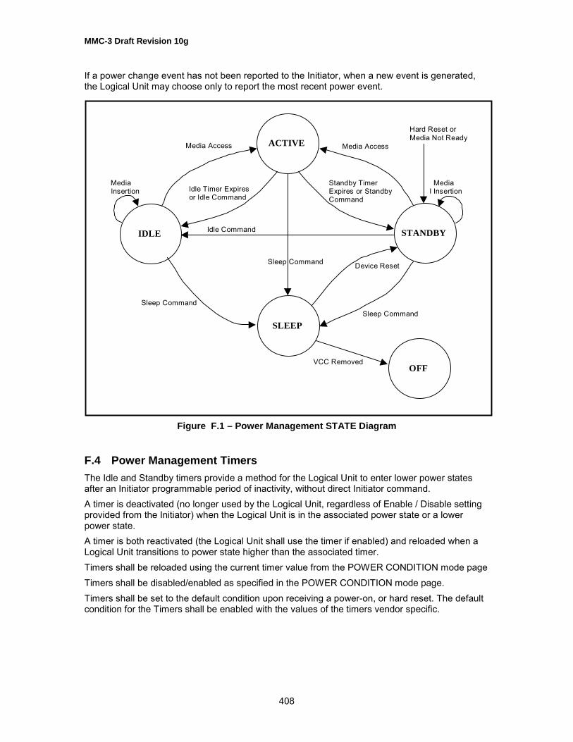
MMC-3 Draft Revision 10g
408
If a power change event has not been reported to the Initiator, when a new event is generated,the Logical Unit may choose only to report the most recent power event.
Figure F.1 – Power Management STATE Diagram
F.4 Power Management TimersThe Idle and Standby timers provide a method for the Logical Unit to enter lower power statesafter an Initiator programmable period of inactivity, without direct Initiator command.A timer is deactivated (no longer used by the Logical Unit, regardless of Enable / Disable settingprovided from the Initiator) when the Logical Unit is in the associated power state or a lowerpower state.A timer is both reactivated (the Logical Unit shall use the timer if enabled) and reloaded when aLogical Unit transitions to power state higher than the associated timer.Timers shall be reloaded using the current timer value from the POWER CONDITION mode pageTimers shall be disabled/enabled as specified in the POWER CONDITION mode page.Timers shall be set to the default condition upon receiving a power-on, or hard reset. The defaultcondition for the Timers shall be enabled with the values of the timers vendor specific.
ACTIVE
STANDBYIDLE
SLEEP
OFF
Media Insertion
MediaI Insertion
Media Access Media Access
Idle Timer Expires or Idle Command
Standby Timer Expires or Standby Command
Idle Command
Sleep Command
Sleep Command
Device Reset
Sleep Command
Hard Reset or Media Not Ready
VCC Removed

MMC-3 Draft Revision 10g
409
F.5 Standby TimerIf the Standby Timer expires the Logical Unit shall attempt to flush all buffers.If this operation fails, the Logical Unit shall remain in the current power state, and the Standbytimer is reloaded. If the flush succeeds, the Logical Unit shall enter the Standby State.
Table F.2 – State Transition Events and Status
InitialState
ResultantState
Cause of Transition NotificationClass
Event
Active Active Unsuccessful Idle, Standby, or Sleep command Power PwrChg-FailIdle Successful completion of Idle command Power PwrChg-SuccIdle The expiration of Idle timer Power PwrChg-SuccStandby Successful completion of Standby command Power PwrChg-SuccStandby The expiration of Standby timer, all Buffers are
emptyPower PwrChg-Succ
Sleep Successful completion of Sleep command Power PwrChg-SuccIdle Idle Successful completion of Idle command Power PwrChg-Succ
Idle Unsuccessful Idle, Standby, or Sleep command Power PwrChg-FailIdle Insertion of media and ready to use Media New MediaStandby The expiration of Standby timer, all buffers are
emptyPower PwrChg-Succ
Standby Successful completion of Standby command Power PwrChg-SuccSleep Successful completion of Sleep command Power PwrChg-SuccActive Receptions of a command that reloads both
timersPower PwrChg-Succ
Standby Standby Successful completion of Standby command Power PwrChg-SuccStandby Unsuccessful Idle, Standby, or Sleep command Power PwrChg-FailStandby Insertion of media and ready to use Media NewMediaIdle Successful completion of Idle command Power PwrChg-SuccSleep Successful completion of Sleep command Power PwrChg-SuccActive Receptions of a command that reloads both
timersPower PwrChg-Succ
Any Standby A power-on, or hard reset occurred, or theLogical Unit becomes NOT READY
Power PwrChg-Succ
Sleep Standby Device Reset Power PwrChg-Succ
Commands issued by the Initiator shall have an effect on the timers implemented by the LogicalUnit. The effect is defined in Table F.3.

MMC-3 Draft Revision 10g
410
Table F.3 – Effects of Initiator Commands on Timers
Initiator Command Issued Timer Effects CommentsBLANK Reload Both Recordable onlyCHANGE DEFINITION NoneCLOSE TRACK Reload Both Recordable onlyCOMPARE Reload Both SCSI onlyEXCUTE LOGICAL UNIT DIAGNOSTIC Reload Both ATA commandSYNCHRONIZE CACHE Reload BothFORMAT UNIT Reload Both Recordable onlyGET CONFIGURATION NoneGET EVENT/STATUS NOTIFICATION NoneINQUIRY NoneLOAD/UNLOAD MEDIUM Reload BothLOCK/UNLOCK CACHE None SCSI only. A Lock Cache command shall prevent
the Logical Unit from entering Standby or Sleepstates.
LOG SELECT/SENSE None SCSI onlyMECHANISM STATUS NoneMODE SELECT May Reload
TimersA MODE SELECT command that changes theStandby or Idle timers shall reload the timer.
MODE SENSE NonePLAY AUDIO MSF Reload BothPREFETCH Reload Both SCSI onlyPREVENT ALLOW MEDIUM REMOVAL Reload StandbyREAD (12) Reload BothREAD BUFFER Reload StandbyREAD CD/DVD CAPACITY Reload BothREAD CD Reload BothREAD CD MSF Reload BothREAD DISC INFORMATION Reload BothREAD DVD STRUCTURE Reload BothREAD FORMATTABLE CAPACITIES Reload StandbyREAD LONG Reload Both SCSI onlyREAD TRACK INFORMATION Reload BothREAD SUB-CHANNEL Reload BothREAD TOC/PMA/ATIP Reload Both

MMC-3 Draft Revision 10g
411
Table F.3 – Effects of Initiator Commands on Timers (cont.)
Initiator Command Issued Timer Effects Comments
RELEASE None SCSI onlyREPAIR TRACK Reload Both Sequential CD/DVD RecordableREPORT KEY Reload BothGET PERFORMANCE Reload Both May need to access mediaREQUEST SENSE NoneRESERVE None SCSI onlyRESERVE TRACK Reload Both Recordable onlyREZERO Reload Both SCSI onlySCAN Reload BothSEEK Reload BothSEND EVENT Reload Both May effect media accessSEND KEY Reload BothSEND DVD STRUCTURE Reload Both DVD RecordableSEND OPC INFORMATION Reload Both Recordable onlySET CD SPEED Reload Both ObsoleteSET READ AHEAD Reload BothSET STREAMING Reload BothSTART STOP UNIT See Start Stop Unit
commandTEST UNIT READY Reload BothVERIFY Reload BothWRITE Reload Both Recordable onlyWRITE AND VERIFY (10) Reload Both Recordable onlyDevice Reset Reload Both Reset operation, the Logical Unit shall not return to
default timer conditions.Other commands Vendor Specific
F.6 Power Management Status ReportingThe POWER STATUS field of the GET EVENT/STATUS NOTIFICATION (Power ManagementClass) event data shall always report the current Logical Unit power state. This provides amechanism for the Initiator to query the current Power State, irrespective of state transitions.
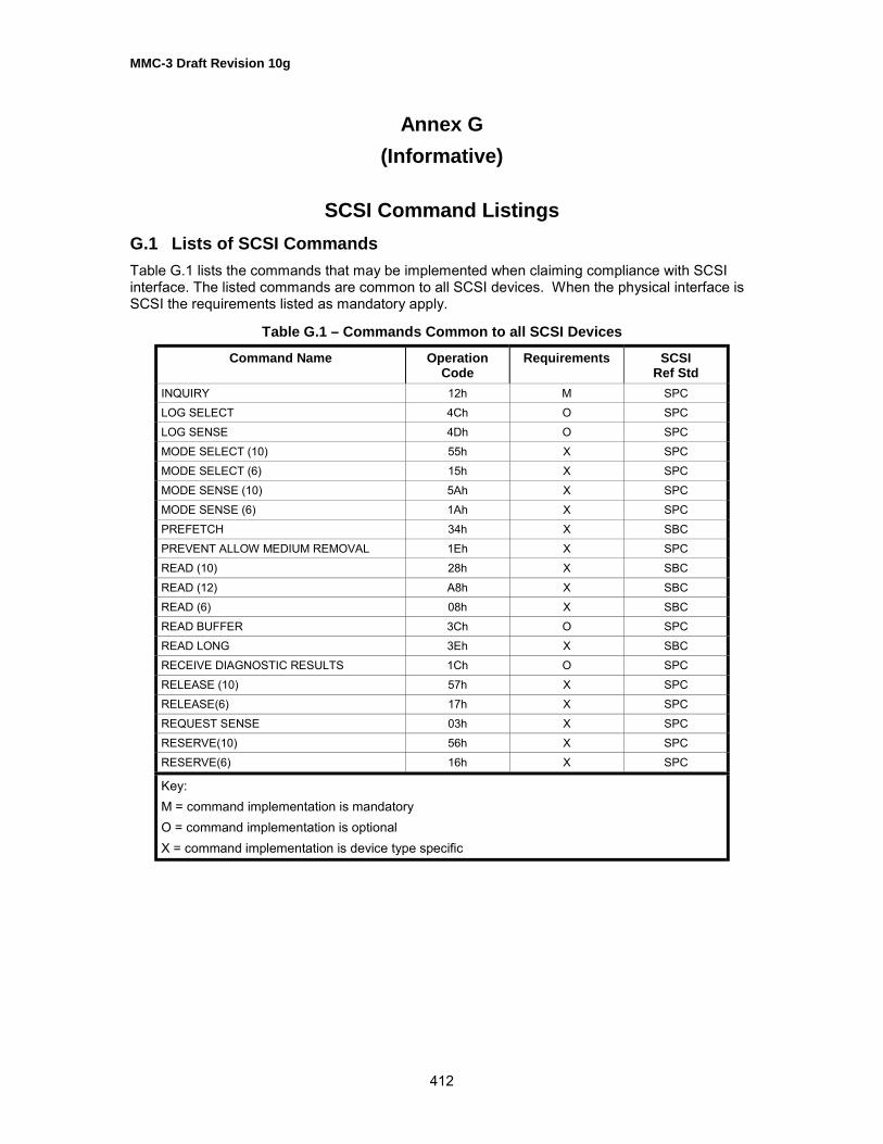
MMC-3 Draft Revision 10g
412
Annex G(Informative)
SCSI Command ListingsG.1 Lists of SCSI CommandsTable G.1 lists the commands that may be implemented when claiming compliance with SCSIinterface. The listed commands are common to all SCSI devices. When the physical interface isSCSI the requirements listed as mandatory apply.
Table G.1 – Commands Common to all SCSI Devices
Command Name OperationCode
Requirements SCSIRef Std
INQUIRY 12h M SPCLOG SELECT 4Ch O SPCLOG SENSE 4Dh O SPCMODE SELECT (10) 55h X SPCMODE SELECT (6) 15h X SPCMODE SENSE (10) 5Ah X SPCMODE SENSE (6) 1Ah X SPCPREFETCH 34h X SBCPREVENT ALLOW MEDIUM REMOVAL 1Eh X SPCREAD (10) 28h X SBCREAD (12) A8h X SBCREAD (6) 08h X SBCREAD BUFFER 3Ch O SPCREAD LONG 3Eh X SBCRECEIVE DIAGNOSTIC RESULTS 1Ch O SPCRELEASE (10) 57h X SPCRELEASE(6) 17h X SPCREQUEST SENSE 03h X SPCRESERVE(10) 56h X SPCRESERVE(6) 16h X SPC
Key:M = command implementation is mandatoryO = command implementation is optionalX = command implementation is device type specific

MMC-3 Draft Revision 10g
413
Table G.1 – Commands Common to all SCSI Devices (continued)
Command Name OperationCode
Requirements SCSIRef Std
SEEK (10) 2Bh X SBCSEEK (6) 0Bh X SCSI-2SEND DIAGNOSTIC 1Dh O SPCSET LIMITS (10) 33h X SBCSET LIMITS (12) B3h X SBCSTART STOP UNIT 1Bh X SBCTEST UNIT READY 00h M SPCVERIFY (10) 2Fh X SBCVERIFY (12) AFh X SBCWRITE BUFFER 3Bh X SPC
Key:M = command implementation is mandatoryO = command implementation is optionalX = command implementation is device type specific
The following command codes are vendor-specific:02h,05h,06h,09h,0Ch through 11h,13h,14h,19h,20h through 24h,26h,27h,29h,and C0h through FFh.

MMC-3 Draft Revision 10g
414
Annex H(Informative)
Implementation of FeaturesH.1 What Is a Feature?A Feature is an atomic unit of functionality.The descriptions of Features in this document appear complex, however, these descriptionsdescribe almost nothing new; they are simply the descriptions of existing legacy behavior. Theonly new parts are the descriptors themselves that are either static identification blocks or groupsof information that the Logical Unit shall already have to operate, even in a legacy behavior. Forexample, a Logical Unit shall internally identify whether or not a PLAY AUDIO command maysucceed; Features are simply a way to let the Initiator in on the secret.Previously, new devices had to make a choice: to look completely like an old device with addedfunctionality or as a new device not compatible with old drivers. Feature and Profiles, an Initiatorcan first determine if the �right� driver is available by examining the Profiles. If �the� right driverisn�t available, the Initiator can identify operable subsets when multiple Profiles are reported.Finally, the Initiator can identify basic functions to use the device via the Feature reporting
H.2 HistoryThe separation of status and error reporting is very important in multitasking environments.Typically, the operating system needs to constantly be aware of the status of the drive. Variousapplications, operating through a variety of OS interfaces, may also need to be aware of LogicalUnit status. Reporting of status via errors breaks down in this environment; only one process ismade aware of state changes via the error, while other processes cannot obtain the same stateinformation because the error (status change) has already been reported to the Initiator(according to the drive).Features do not replace legacy behavior. Features, in most cases, define a subset of legacybehavior. Several Features, taken together, are generally equivalent to legacy devices of thesame type. Error and status reporting in legacy Initiator environments is the same as legacydevices, without any special mode setting.The Features described in Mt. Fuji 2 add something new: reporting. Legacy devices, whileimplementing the content of the Features, did not have any mechanism to report specifically thedrive�s capabilities. The closest mechanism that has existed is a command that reportedimplemented commands. Implemented mode pages are also reportable via standardmechanisms. However, a command is more than an operation code (OpCode). A whole set ofcommands, mode pages, and behavior needs to be grouped together to be useful. For example,write once MO, hard disk drives, and CD-R all use the WRITE command, but it is impossible touse the same strategies for writing these three media. Typically, different drivers or fragments ordrivers are used for each kind of media. The previous mechanism would only identify that theWRITE command was implemented, but could not identify how to use it.The capabilities of a particular Logical Unit may change at arbitrary times. The most commonexample of this is seen in a removable medium device. Even a basic removable magneticmedium device changes: from a random read/write device to a virtually less functional devicewhen the medium is removed. Multi-function devices can change their behavior even moreradically when they accept a variety of physical and logical formats.Before Features, Initiators had to use a trial and error method for determining what would orwould not function. Medium codes became outdated even before publication of the relevantstandard, and still were not adequate to describe all media. The Profiles, also introduced in Mt.

MMC-3 Draft Revision 10g
415
Fuji 2, provide an equivalent to the medium type. However, the Profile does not indicate exactcapabilities for the drive/medium system, only a generic identification of core capabilities.Feature reporting is not completely new. Operating systems first identify a driver via the devicetype. The device type implied a core set of functions, e.g. a CD-ROM Logical Unit would supportREAD, READ TOC, etc. However, even these commands would not work if no medium wereloaded. A driver would determine media status by trying a few commands and examining theerror codes. After determining that media was present, a driver would have to probe to find outabout additional Features such as audio or medium changers. Features were �reportable,� buteach Feature had a different mechanism, and many of the mechanisms relied on the success orfailure of special �key� commands.
H.3 Implementation of FeaturesThere are only two requirements to fully implement Features. The first is the GETCONFIGURATION command. This command is a very basic reporting command that reportssome very static information; only a few Features have any dynamic fields; most Features haveonly one bit that changes. The command is a form of Inquiry: a technique for the Initiator toidentify the device on the bus. The GET CONFIGURATION command simply provides moredetail, and the information reported is expected to be dynamic.Implementation of Feature reporting via the GET CONFIGURATION command is simple: theimage of the result data can be copied from device ROM to its buffer, a few fields set withinformation already known to the Logical Unit (such as the block size), and a few bits setaccording to already existing flags in the firmware (i.e. DVD vs. CD, audio tracks present, etc.).Devices with non-removable media may have a completely static image that is reported. If astarting point other than the beginning is requested, the Logical Unit walks the table to find thefirst requested Feature, subtracts the offset from the data length, and transfers data starting at thesame offset.The second part of Features is reporting when the Features change. It is important for theInitiator to know which operations function with the Logical Unit at any given moment.Preemptive reporting of Feature changes greatly eases Initiator implementations by reducing thenumber of error conditions that need to be handled. The GET EVENT/STATUS NOTIFICATIONcommand is used for status change reporting (an �Event.�) In many drives, implementationsimply requires recording an event whenever a UNIT ATTENTION is generated.As mentioned earlier, Features are not new; their reporting is. This reporting has become veryimportant in modern environments. Multiple drivers are talking to the same device, doing differenttasks. For example, a DVD-ROM Logical Unit may use the basic CD-ROM driver when a CD isinstalled, and another driver when a DVD is installed, and both a basic DVD driver and a separatecopy protection process when copy protected media is mounted. All of these processes shallinteract well to provide seamless and solid support. Feature reporting provides a method for cleaninteraction.
H.4 CompatibilityDrives implementing Feature reporting are fully compatible with legacy systems.The GET CONFIGURATION changes no behavior of the drive; it simply reports existing stateinformation. Repeated GET CONFIGURATION commands shall report the same information(unless the user inserts or removes the medium, etc.). GET CONFIGURATION never changesany state information in the drive, including unit attention conditions.The GET EVENT/STATUS NOTIFICATION command shall not return CHECK CONDITIONstatus to report a unit attention condition. Any pending unit attention condition for which acorresponding event is reported shall not be cleared for the drive.

MMC-3 Draft Revision 10g
416
H.5 SummaryFeatures do not radically modify any legacy behavior or functionality. The only new parts involvereporting of behavior, and typically reflect state information already required of any firmwareimplementation, via two new commands. One command reports status, and the other notifies theInitiator that the status may have changed.The benefits include easier coding of highly robust drivers, fewer error conditions, and forwardand backward compatibility with operating system drivers.

MMC-3 Draft Revision 10g
417
Annex I(Informative)
MMC Command ListingsTable I.1 – Multimedia Commands - Alphabetically
Command Name Op Code Reference
BLANK A1h 5.2CLOSE TRACK/SESSION 5Bh 5.3FORMAT UNIT 04h 5.4GET CONFIGURATION 46h 5.5GET EVENT/STATUS NOTIFICATION 4Ah 5.6GET PERFORMANCE ACh 5.7INQUIRY 12h SPCLOAD/UNLOAD CD/DVD A6h 5.8MECHANISM STATUS BDh 5.9MODE SELECT (10) 55h SPCMODE SENSE (10) 5Ah SPCPAUSE/RESUME 4Bh 5.10PLAY AUDIO (10) 45h 5.11PLAY AUDIO (12) A5h 5.12PLAY AUDIO MSF 47h 5.13PREVENT ALLOW MEDIUM REMOVAL 1Eh SPCREAD (10) 28h SPCREAD (12) A8h 5.14READ BUFFER CAPACITY 5Ch 5.15READ CAPACITY 25h 5.16READ CD BEh 5.17READ CD MSF B9h 5.18READ DISC INFORMATION 51h 5.19READ DVD STRUCTURE ADh 5.20READ FORMAT CAPACITIES 23h 5.21READ SUB-CHANNEL 42h 5.22READ TOC/PMA/ATIP 43h 5.23READ TRACK INFORMATION 52h 5.24REPAIR TRACK 58h 0REPORT KEY A4h 5.26REQUEST SENSE 03h SPCRESERVE TRACK 53h 5.27SCAN BAh 5.28SEEK (10) 2Bh SBCSEND CUE SHEET 5Dh 5.29SEND DVD STRUCTURE BFh 5.30SEND EVENT A2h 5.31SEND KEY A3h 5.32SEND OPC INFORMATION 54h 5.33SET CD SPEED BBh 5.34

MMC-3 Draft Revision 10g
418
Table I.1 – Multimedia Commands – Alphabetically (cont.)
Command Name Op Code Reference
SET READ AHEAD A7h 5.35SET STREAMING B6h 5.36START STOP UNIT 1Bh SBCSTOP PLAY/SCAN 4Eh 5.37SYNCHRONIZE CACHE 35h 5.38TEST UNIT READY 00h SPCVERIFY (10) 2Fh SBCWRITE (10) 2Ah 5.39WRITE (12) AAh 5.40WRITE AND VERIFY (10) 2Eh 5.41
Table I.2 – Multimedia Commands - by OpCode
Command Name Op Code Reference
TEST UNIT READY 00h SPCREQUEST SENSE 03h SPCFORMAT UNIT 04h 5.4INQUIRY 12h SPCSTART STOP UNIT 1Bh SBCPREVENT ALLOW MEDIUM REMOVAL 1Eh SPCREAD FORMAT CAPACITIES 23h 5.21READ CAPACITY 25h 5.16READ (10) 28h SPCWRITE (10) 2Ah 5.39SEEK (10) 2Bh SBCWRITE AND VERIFY (10) 2Eh 5.41VERIFY (10) 2Fh SBCSYNCHRONIZE CACHE 35h 5.38READ SUB-CHANNEL 42h 5.22READ TOC/PMA/ATIP 43h 5.23PLAY AUDIO (10) 45h 5.11GET CONFIGURATION 46h 5.5PLAY AUDIO MSF 47h 5.13GET EVENT/STATUS NOTIFICATION 4Ah 5.6PAUSE/RESUME 4Bh 5.10STOP PLAY/SCAN 4Eh 5.37READ DISC INFORMATION 51h 5.19READ TRACK INFORMATION 52h 5.24RESERVE TRACK 53h 5.27SEND OPC INFORMATION 54h 5.33MODE SELECT (10) 55h SPCREPAIR TRACK 58h 0MODE SENSE (10) 5Ah SPCCLOSE TRACK/SESSION 5Bh 5.3
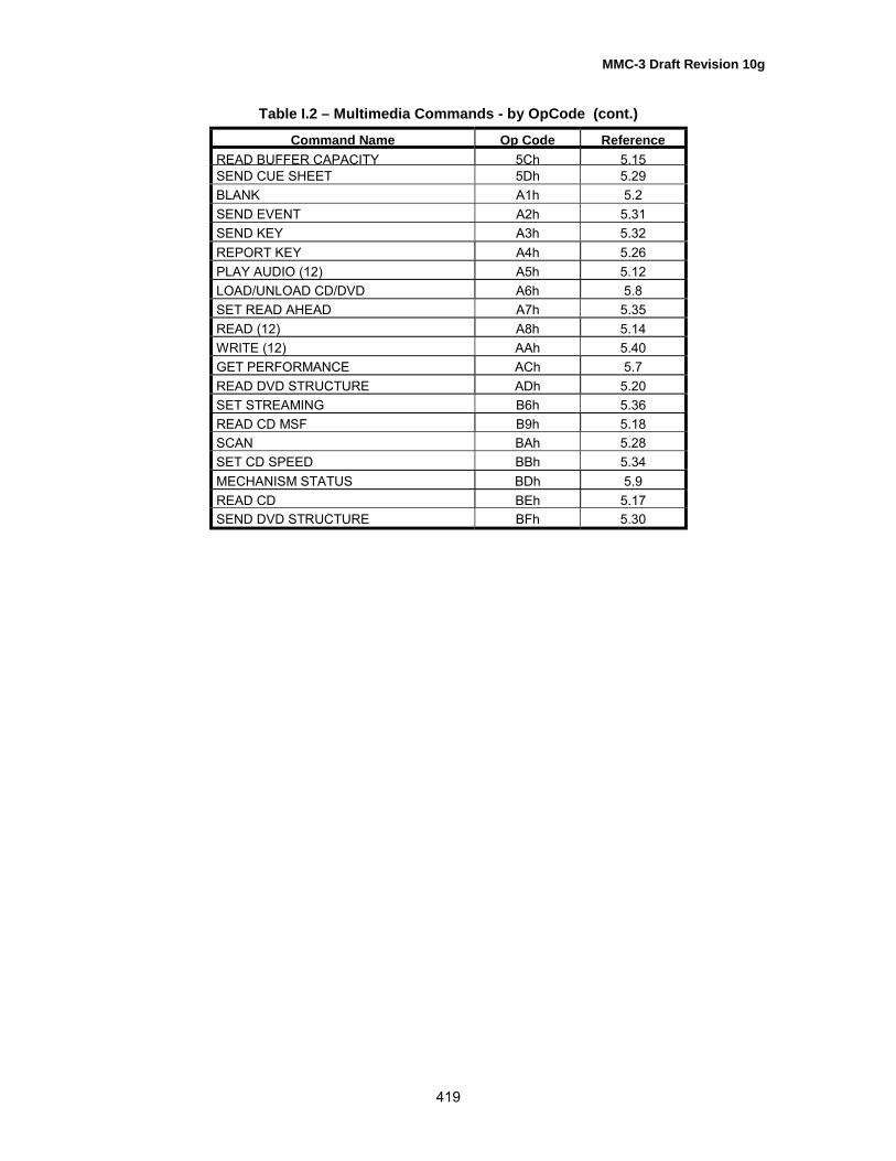
MMC-3 Draft Revision 10g
419
Table I.2 – Multimedia Commands - by OpCode (cont.)
Command Name Op Code ReferenceREAD BUFFER CAPACITY 5Ch 5.15SEND CUE SHEET 5Dh 5.29BLANK A1h 5.2SEND EVENT A2h 5.31SEND KEY A3h 5.32REPORT KEY A4h 5.26PLAY AUDIO (12) A5h 5.12LOAD/UNLOAD CD/DVD A6h 5.8SET READ AHEAD A7h 5.35READ (12) A8h 5.14WRITE (12) AAh 5.40GET PERFORMANCE ACh 5.7READ DVD STRUCTURE ADh 5.20SET STREAMING B6h 5.36READ CD MSF B9h 5.18SCAN BAh 5.28SET CD SPEED BBh 5.34MECHANISM STATUS BDh 5.9READ CD BEh 5.17SEND DVD STRUCTURE BFh 5.30
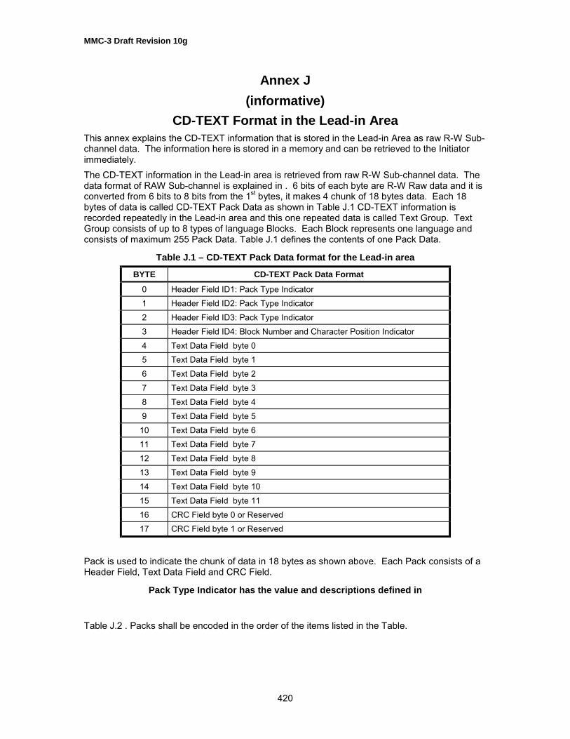
MMC-3 Draft Revision 10g
420
Annex J(informative)
CD-TEXT Format in the Lead-in AreaThis annex explains the CD-TEXT information that is stored in the Lead-in Area as raw R-W Sub-channel data. The information here is stored in a memory and can be retrieved to the Initiatorimmediately.The CD-TEXT information in the Lead-in area is retrieved from raw R-W Sub-channel data. Thedata format of RAW Sub-channel is explained in . 6 bits of each byte are R-W Raw data and it isconverted from 6 bits to 8 bits from the 1st bytes, it makes 4 chunk of 18 bytes data. Each 18bytes of data is called CD-TEXT Pack Data as shown in Table J.1 CD-TEXT information isrecorded repeatedly in the Lead-in area and this one repeated data is called Text Group. TextGroup consists of up to 8 types of language Blocks. Each Block represents one language andconsists of maximum 255 Pack Data. Table J.1 defines the contents of one Pack Data.
Table J.1 – CD-TEXT Pack Data format for the Lead-in area
BYTE CD-TEXT Pack Data Format
0 Header Field ID1: Pack Type Indicator1 Header Field ID2: Pack Type Indicator2 Header Field ID3: Pack Type Indicator3 Header Field ID4: Block Number and Character Position Indicator4 Text Data Field byte 05 Text Data Field byte 16 Text Data Field byte 27 Text Data Field byte 38 Text Data Field byte 49 Text Data Field byte 5
10 Text Data Field byte 611 Text Data Field byte 712 Text Data Field byte 813 Text Data Field byte 914 Text Data Field byte 1015 Text Data Field byte 1116 CRC Field byte 0 or Reserved17 CRC Field byte 1 or Reserved
Pack is used to indicate the chunk of data in 18 bytes as shown above. Each Pack consists of aHeader Field, Text Data Field and CRC Field.
Pack Type Indicator has the value and descriptions defined in
Table J.2 . Packs shall be encoded in the order of the items listed in the Table.

MMC-3 Draft Revision 10g
421
Table J.2 – Pack Type Indicator Definitions
Value Descriptions
80h Title of Album name(ID2=00h) or Track Titles (ID2=01h...63h)81h Name(s) of the performer(s) (in ASCII)82h Name(s) of the songwriter(s) (in ASCII)83h Name(s) of the composer(s) (in ASCII)84h Name(s) of the arranger(s) (in ASCII)85h Message(s) from content provider and/or artist (in ASCII)86h Disc Identification information87h Genre Identification and Genre information88h Table of Content information
89h Second Table of Content information8Ah Reserved8Bh Reserved8Ch Reserved8Dh Reserved for content provider only8Eh UPC/EAN code of the album and ISRC code of each track8Fh Size information of the Block
The track Number Indicator is accompanied by 2 information fields. The MSB of this byte in theExtension Flag and is normally set to 0b. If it is set to 1b, the Pack is used for an extendedapplication that is beyond the scope of this document. The rest of the byte is used for TrackNumber or Pack Element Number. Track Number is used when the Text Data field belongs to thetrack. If the Pack is independent of the Track, this field indicates Pack Element Number thatdepends on the type of the Pack.Sequence Number Indicator is the number incrementally increased from the first Pack to the endin each Block. It starts from 00h to FFh.Block Number and Character Position Indicator contains 3 fields of information defined in TableJ.3.
Table J.3 – Block Number Character Position
Bit 7 Bit 6 Bit 5 Bit 4 Bit 3 Bit 2 Bit 1 Bit 0
DBCC Block Number Character Position
Bit 7 is the Double Byte Character Code indication, that indicates if Text Data Field contains theDouble Byte Character Code or not. If it is set to 0b, the Single Byte Character Code is used.Bit 4 to 6, 3 bits, indicate the Block Number of the Block to which the Pack belongs. A Block isused to indicate a set of text information representing one particular language. It can be used upto 8 at the same time.Bit 0 to Bit 3, indicate the Character Position. It is the number of character in the strings thatbelongs to the Text Data Field in the previous Pack. The Character Position starts from 0 to 15and 15 indicates that the first character belongs to the one before the previous Pack. When thecharacter code is double byte code, a set of 2 bytes in the Text Data Field is counted at one.

MMC-3 Draft Revision 10g
422
A null code is also counted as a character, that indicates termination of each strings.Character Position is not used in Packs with ID1=88h, 89h and 8Fh. 00h shall be used in allthese Packs.A Text Data Field consists of 12 bytes. It contains either character strings or binary informationdepending on the type of Pack. All data in this field shall be transferred as recorded on the disc.Packs except ID1=88h, 89h and 8Fh shall contains character strings in the Text Data Field. IfPacks with ID1=80h to 85h, and 8Eh are used, a character strings for each track shall beprovided.A character string consists of series of characters and a terminator(One null code for single byte,two null code for double byte)`The size of a character string is recommended to be less than 160 bytes. If a character stringdoes not fit in a Text Data Field of a Pack, it is continued onto the succeeding Packs. Thesucceeding character string shall be encoded starting at the next byte in the Text Data Field afterthe terminator of the current string. Unused bytes in the Text Data Field shall be filled with nullcodes.In case the same character stings is used for consecutive tracks, the Tab Indicator may be usedto indicate the same as previous track. It is a single tab code (09h) for single byte codes, and twotab codes for double bytes character codes. It shall not used for the first track.Packs with ID1=86h, 87h, 88h, 89h and 8Fh contains binary information in the Text Data Field.CRC Field consists of 2 bytes. Initiator system may use these bytes to check errors in the Pack.The polynomial is X16 + X12 + X5 + 1. All bits shall be inverted. This field is not mandatory forsupporting CD-TEXT data.

MMC-3 Draft Revision 10g
423
Annex K(Informative)
Using MRW Formatted MediaK.1 A CD-MRW EXAMPLEA CD-RW disc is mounted into a MRW capable CD-RW drive. The lead-in ATIP on this discindicates that the first lead-in begins at 97:38:20 and the last possible lead-out begins at75:04:12. Suppose the disc is completely formatted as a CD MRW disc.The MRW format requires that the program area be formatted as a single track of fixed packetswith 32 user sectors each. This yields a maximum of 337 812 sectors within the program area(from 00:00:00 to but not including 75:04:12). The first user sector is found at 00:02:00. Thismeans that the first packet overhead invades the track 1 pre-gap by 5 sectors. So, 337 667sectors may be dedicated to fixed packets. This yields 8 658 packets with 5 sectors remaining(337 812 - (150 - 5) = 39 * 8 658 + 5). The 5 extra sectors are moved into the lead-out.The GAA requires 32 packets from the beginning of the program area while the STA requires 33packets at the end of the program area. This leaves 8 658 - 65 = 8593 packets for the DMA.Each SA/DA pair is 144 packets in length. 8 593 = 59*144 + 97, so we may have 59 SA/DA pairswith 97 packets remaining. Of these 97 packets, 8 are reserved for the final SA, leaving 89packets for the final DA.The actual number of user sectors in the DMA is 32*(59*136+89) = 25 916.There are a few significant disc addresses of interest (Table K.1 � MRW Example: SignificantAddresses):
Table K.1 – MRW Example: Significant Addresses
MSF LBA Significance
00:00:00 - Start of program area of the disc.00:02:00 0 First user sector of GAA00:18:40 1023 Last user sector of GAA00:18:43 - Link block separating GAA from DMA00:22:60 0 First user sector of DMA:
First user sector of first packet of first DA74:48:34 259615 Last user sector of DMA:
Last user sector of last packet of last DA75:04:07 - Actual lead-out start address:
Link block separating last STA packet and lead-out75:04:12 - Last possible start time for start of lead-out according to ATIP
After unit attention conditions have been cleared, the initiator may choose to collect informationabout this disc.

MMC-3 Draft Revision 10g
424
Next, examples of the data returned for:READ CAPACITYREAD DISC INFORMATIONREAD TRACK INFORMATIONREAD TOC/PMA/ATIP
K.1.1 READ CAPACITY CommandThe READ CAPACITY command response is the last LBA in the address space and the blocksize.
Table K.2 – MRW Example: Read Capacity Results
Byte Field Value when LBA Space = GAA Value when LBA Space = DMA
0..3 Last LBA 1 023 (3FFh) 259 615 (3F61Fh)4..7 Block size 2 048 (800h) 2 048 (800h)
Note that regardless of the current LBA Space, the block size is 2 048 bytes (0800h) bytes persector.
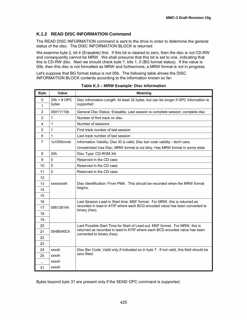
MMC-3 Draft Revision 10g
425
K.1.2 READ DISC INFORMATION CommandThe READ DISC INFORMATION command is sent to the drive in order to determine the generalstatus of the disc. The DISC INFORMATION BLOCK is returned.We examine byte 2, bit 4 (Erasable) first. If this bit is cleared to zero, then the disc is not CD-RWand consequently cannot be MRW. We shall presume that this bit is set to one, indicating thatthis is CD-RW disc. Next we should check byte 7, bits 1, 0 (BG format status). If the value is00b, then this disc is not formatted as MRW and furthermore, a MRW format is not in progress.Let's suppose that BG format status is not 00b. The following table shows the DISCINFORMATION BLOCK contents according to the information known so far:
Table K.3 – MRW Example: Disc Information
Byte Value Meaning
01
20h + # OPCbytes
Disc Information Length: At least 32 bytes, but can be longer if OPC information issupported
2 00011110b General Disc Status: Erasable, Last session is complete session, complete disc3 1 Number of first track on disc4 1 Number of sessions5 1 First track number of last session6 1 Last track number of last session7 1x1000mmb Information Validity: Disc ID is valid, Disc bar code validity - don't care,
Unrestricted Use Disc, MRW format is not dirty, Has MRW format in some state8 20h Disc Type: CD-ROM XA9 0 Reserved in the CD case
10 0 Reserved in the CD case11 0 Reserved in the CD case12131415
xxxxxxxxh Disc Identification: From PMA. This should be recorded when the MRW formatbegins.
16171819
00612614hLast Session Lead-in Start time: MSF format. For MRW, this is returned asrecorded in lead-in ATIP where each BCD encoded value has been converted tobinary (hex).
20212223
004B040ChLast Possible Start Time for Start of Lead-out: MSF format. For MRW, this isreturned as recorded in lead-in ATIP where each BCD encoded value has beenconverted to binary (hex).
2425...31
xxxxhxxxxhxxxxhxxxxh
Disc Bar Code: Valid only if indicated so in byte 7. If not valid, this field should bezero filled.
Bytes beyond byte 31 are present only if the SEND OPC command is supported.

MMC-3 Draft Revision 10g
426
K.1.3 READ TRACK INFORMATION CommandNext, our initiator sends the READ TRACK INFORMATION command for track 1. The TRACKINFORMATION BLOCK is returned as follows:
Table K.4 – MRW Example: Track Information
Byte Value Meaning
01
20h Track Information Length: 32 for CD discs
2 1 Track Number3 1 Session Number4 0 Reserved5 0000 0111b Track Status: Track mode is incrementally recorded data, copying is not prohibited6 10110010b Track Status: Reserved, not blank, fixed packet, mode 2 sectors7 000000x0b Validities: Last recorded address - don't care, next writable address - not valid89
1011
00000000h Track Start Address:This is given in LBA format. It is always zero for MRW.
12131415
00000000h Next Writable Address:Not valid on fixed packet formatted discs. Should be zero filled.
16171819
00000000h Free Blocks:Not valid on fixed packet formatted discs. Should be zero filled.
20212223
00000020h Fixed Packet Size:This value is 32 for CD MRW
24252627
GAA: 1 024DMA: 259 616
Track Size: This is the number of user sectors in the track.
28293031
xxxxxxxxh Last Recorded Address: Not required.

MMC-3 Draft Revision 10g
427
K.1.4 READ TOC/PMA/ATIP CommandThe READ TOC/PMA/ATIP command requires that the initiator select one of 6 forms:
form 0: Legacy TOC (from SCSI2)form 1: Multi-session informationform 2: Full TOC - all information recorded in the lead-in(s), presented in a non-redundant wayform 3: PMA - all information recorded in the PMA, presented in a non-redundant wayform 4: ATIP - disc specific parameters from the disc lead-in, encoded in the ATIPform 5: CD-TEXT - valid only for CD audio discs
K.1.4.1 Form 0 TOC: SCSI-2 TOC, List of Track DescriptorsTable K.5 shows the expected data returned for the form 0 TOC request.
Table K.5 – MRW Example: Form 0 TOC (SCSI-2 TOC)
Byte MSF = 0 MSF = 1 Meaning
01
18 18 Data length
2 1 1 First Track number3 1 1 Last Track Number
TOC Descriptor: Track 1
0 0 0 Reserved1 17h 17h ADR/CONTROL2 1 1 Track Number3 0 0 Reserved4567
GAA: 0DMA: 0
GAA: 00:02:00DMA: 00:22:60
Track Start Address
TOC Descriptor: Lead-out
0 0 0 Reserved1 16h 16h ADR/CONTROL2 AAh AAh Track Number3 0 0 Reserved4567
GAA: 1 024DMA: 259 712
GAA: 00:18:43DMA: 74:48:37
Track Start Address
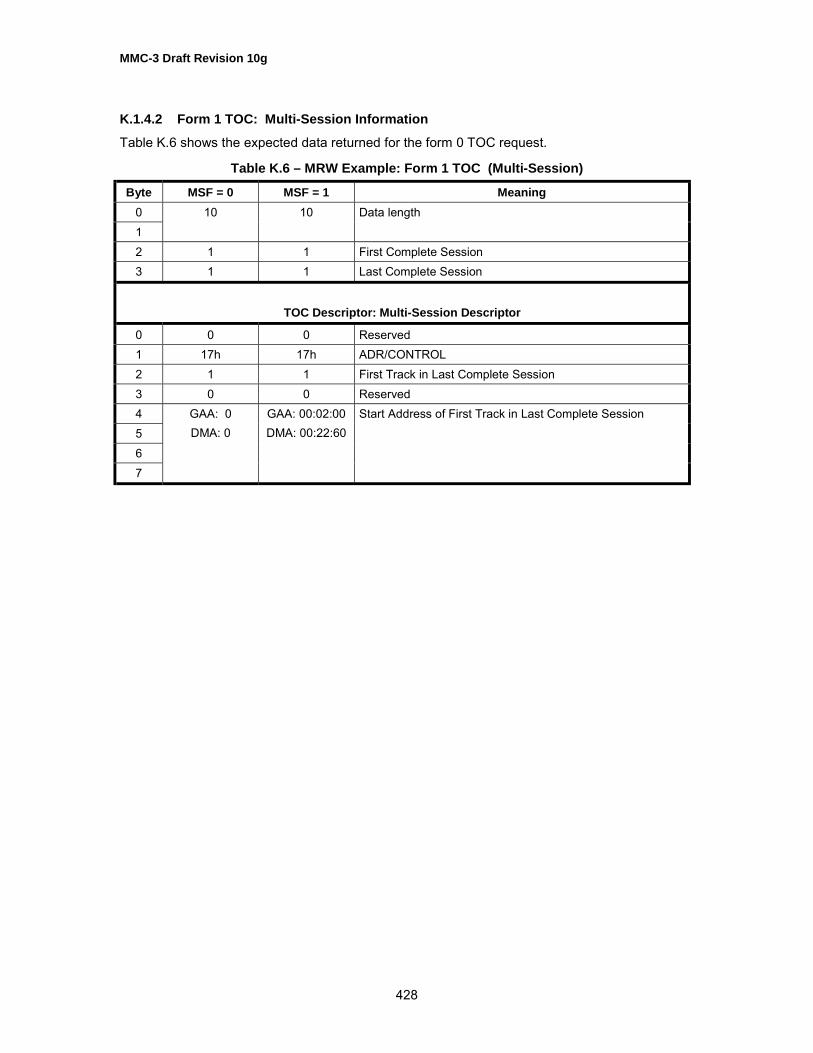
MMC-3 Draft Revision 10g
428
K.1.4.2 Form 1 TOC: Multi-Session InformationTable K.6 shows the expected data returned for the form 0 TOC request.
Table K.6 – MRW Example: Form 1 TOC (Multi-Session)
Byte MSF = 0 MSF = 1 Meaning01
10 10 Data length
2 1 1 First Complete Session3 1 1 Last Complete Session
TOC Descriptor: Multi-Session Descriptor
0 0 0 Reserved1 17h 17h ADR/CONTROL2 1 1 First Track in Last Complete Session3 0 0 Reserved4567
GAA: 0DMA: 0
GAA: 00:02:00DMA: 00:22:60
Start Address of First Track in Last Complete Session

MMC-3 Draft Revision 10g
429
K.1.4.3 Form 2: Full TOCWhen the MRW format has completed, form 2 TOC shall be reported as described for other CDformats (seeTable K.7). When the MRW format is not complete, the final TOC has not beenrecorded. In this case, the drive shall predict the TOC content. Since some addresses may haveno consistent LBA representation, only the MSF form is supported. Note that because these arenot logical addresses, there is no reference to the LBA Space.
Table K.7 – MRW Example: Form 2 TOC (Full TOC)
Byte MSF = 1 Meaning01
xx Data length
2 1 First Complete Session number3 1 Last Complete Session Number
TOC Descriptor: Track 1
0 1 Session Number1 16h ADR/CONTROL2 0 TNO3 1 POINT: Track number456
mm:ss:ffMIN, SEC, FRAMEAbsolute address of current location
7 0 ZERO89
10
00:02:00PMIN, PSEC, PFRAMEStart address of Track
TOC Descriptor: Point A0
0 1 Session Number1 16h ADR/CONTROL2 0 TNO3 A0h POINT456
mm:ss:ffMIN, SEC, FRAMEAbsolute address of current location
7 0 ZERO8 1 PMIN: First Track Number9 0 PSEC
10 0 PFRAME

MMC-3 Draft Revision 10g
430
Table K.7 – MRW Example: Form 2 TOC (Full TOC), continued
TOC Descriptor: Point A1
0 1 Session Number1 16h ADR/CONTROL2 0 TNO3 A1h POINT456
mm:ss:ffMIN, SEC, FRAMEAbsolute address of current location
7 0 ZERO8 1 PMIN: Last Track Number9 0 PSEC
10 0 PFRAME
TOC Descriptor: Point A2
0 1 Session Number1 16h ADR/CONTROL2 0 TNO3 A0h POINT456
mm:ss:ffMIN, SEC, FRAMEAbsolute address of current location
7 0 ZERO89
10
75:05:51PMIN, PSEC, PFRAMEStart time of lead-out
TOC Descriptor: Point C0
0 1 Session Number1 16h ADR/CONTROL2 0 TNO3 C0h POINT4 xx MIN: Optimum recording power5 0 SEC6 0 FRAME7 0 ZERO8910
97:38:20PMIN, PSEC, PFRAMEAddress of first lead-in according to ATIP

MMC-3 Draft Revision 10g
431
Table K.7 – MRW Example: Form 2 TOC (Full TOC), continued
TOC Descriptor: Point C1
0 1 Session Number1 16h ADR/CONTROL2 0 TNO3 C1h POINT4 xx MIN: ATIP Additional information 001, min byte5 yy SEC: ATIP Additional information 001, sec byte6 zz FRAME: ATIP Additional information 001, frm byte7 0 ZERO8 0 PMIN9 0 PSEC
10 0 PFRAME
K.1.4.4 Form 3: PMAReporting of the PMA values is not changed due to the MRW format.
K.1.4.5 Form 4: ATIPReporting of the ATIP values is not changed due to the MRW format.
K.1.4.6 Form 5: CD-TEXTReporting CD-TEXT data is valid only for CD-DA discs. This form is not valid when a MRWformatted disc is present. If this form is requested, then the drive shall terminate the READTOC/PMA/ATIP command with CHECK CONDITION status and SK/ASC/ASCQ values shall beset to ILLEGAL REQUEST/INVALID FIELD IN CDB.
K.1.5 READ(10), READ(12), READ CD, WRITE(10), WRITE and VERIFY(10),SEEK(10), VERIFY(10) COMMANDS
Each of these commands requires that the initiator provide a starting LBA and (except SEEK) atransfer length. The limits of the requested range has always been governed by the maximumLBA value returned by the READ CAPACITY command.When the MRW Mode Page shows the GAA as current LBA Space, all references to sectorswithin the range 0 through 1023 are valid. If any of the listed commands references a LBAoutside that range, then the command shall be terminated with CHECK CONDITION status andSK/ASC/ASCQ values shall be set to ILLEGAL REQUEST/LOGICAL BLOCK ADDRESS OUTOF RANGE.When the MRW Mode Page shows the DMA as current LBA Space, all references to sectorswithin the range 0 through 259615 are valid. If any of the listed commands references a LBAoutside that range, then the command shall be terminated with CHECK CONDITION status andSK/ASC/ASCQ values shall be set to ILLEGAL REQUEST/LOGICAL BLOCK ADDRESS OUTOF RANGE.

MMC-3 Draft Revision 10g
432
K.2 LEGACY CONSIDERATIONSThis medium could be mounted in several system combinations of Logical Unit and initiatorsoftware. Of course, when all parties are aware of MRW formatted CD-RW media, then thereshould be no misunderstandings. There is an installed base of Logical Units and software thatrecognizes this medium differently. Each combination is highlighted here. The greatest attentionis given to initiator and Logical Unit interaction when the two components are both Mount Rainiercapable.
Table K.8 – MRW: Legacy Combinations
SOFTWARECOMBINATIONS Legacy Software
SystemMRW Aware Software
System
Legacy CD-ROM Logical Unit(Multi-read capable)
1A 1B
MRW Compliant CD-ROMLogical Unit
2A 2B
Legacy CD-RW Logical Unit(at least MMC1)
3A 3B
HARDWARE
MRW Compliant CD-RWLogical Unit
4A 4B
The Legacy hardware cannot be �too old�. There are some minimal requirements:
• Logical Units shall be minimally compliant with OSTA Multi-read in order to read CD-RWmedium.
• Both CD-ROM and CD-RW Logical Units shall be minimally compliant with MMC1.
• A DVD-ROM Logical Unit, which meets the first 2 requirements when CD-RW medium ismounted, may be viewed as an acceptable legacy CD-ROM Logical Unit.
The Legacy software is presumed to be maximally capable with its companion hardware:
• In the case of reading, the legacy system software is capable of reading information stored instandard file systems (e.g. ISO9660, UDF, Joliet).
Note: It is only for the sake of completeness that we describe what might happen in cases1A, 1B, 3A, and 3B. Nothing can be done within this document to make the legacysituations operate better. That work has been done in the format definition document:MRW Defect Management & Physical Formatting revision 1.0
K.2.1 Combinations 1A, 1B: Legacy CD-ROM Logical UnitThe legacy CD-ROM Logical Unit sees a MRW disc as having a single, closed session thatcontains a single fixed packet track with length 32 packets. This Logical Unit sees this disc ashaving a single LBA space that begins at LBA = 0 (00:02:00). The LBAs continue upward,following method 2 addressing (according to Orange Book).

MMC-3 Draft Revision 10g
433
K.2.1.1 With Legacy SoftwareIf no file system was placed within the GAA, then the initiator shall declare that this disc is notinitialized in any recognizable way.If some file system, recognizable by the system software was placed within the GAA, then itexists entirely within the GAA and makes no references into the DMA. No relocations have beenmade within the GAA, so there is no loss. The file system within the GAA may contain automaticrun software that can provide some special function for the user. Minimally, this shall containinformation as described in the CD-MRW DM & PF.
K.2.1.2 With Mount Rainier Aware System SoftwareNote that software which can recognize and read MRW from a legacy Logical Unit is required tooperate differently than software which expects a MRW capable Logical Unit:In the first case, the system software shall perform address translations and defect insertionsIn the second case, the Logical Unit already does all LBA translations and defect replacements.
K.2.2 Combinations 2A, 2B: MRW Compliant CD-ROM Logical UnitWhen the Logical Unit is capable of correctly reading a MRW disc, the system software initiallysees only the LBA Space defined by the DMA. Both legacy and MRW system software sees onlythe file system installed in the DMA.The primary difference with a read-only system is GAA access. The legacy software is unawareof the existence of the GAA and cannot understand how to address it. The MRW compliantsystem software is able to switch addressing to the GAA.
K.2.3 Combinations 3A, 3B: Legacy (MMC1) CD-RW Logical UnitThe legacy CD-RW Logical Unit is unaware of the MRW format and presents the disc to theinitiator as a single session with one fixed packet written track in which the packet size is 32 andthe block type is mode 2, form 1.
K.2.3.1 With Legacy System SoftwareWith this combination: this Logical Unit can write and the legacy system software knows how toask it to write.
K.2.3.2 With Mount Rainier System SoftwareIn this case, the Mount Rainier aware software is aware of the unit�s inability to perform defectmanagement and sector-addressable writes, and shall force read-only access to the medium.
K.2.4 Combinations 4A, 4B: MRW Compliant CD-RW Logical UnitThe most important of these combinations is the case where the system software is MountRainier aware.
K.2.4.1 With Legacy System SoftwareSince the system software is not aware of how to enable writing, the Logical Unit effectivelybecomes a CD-RW Logical Unit.
K.2.4.2 With MRW Aware System SoftwareSince this represents the future, a great deal of attention needs to be given to how the LogicalUnit should implement the updated MMC and how the system software can use the command setto fully utilize the MRW format. This is described from the initiator perspective.
MMC-3 Draft Revision 10g
434
K.2.4.2.1 Determining the Format State of a New MediaWhen a new medium is mounted, a media event is generated. This event is typically discoveredby polling with the Get Event Status Notification command (GESN).
K.2.4.2.2 Case: Discovering that the Media is Formatted/Formatting as a MRW DiscThe GESN poll reports a NewMedia Media Event.The GESN poll reports NoEvent (no additional Media Events to report).The GET CONFIGURATION command is issued, and reports CD-RW Profile and MRW Featuresas current.The READ DISC INFORMATION command is issued.It is discovered that the MRW format status is non-zero.If formatting was started earlier and needs restarting, then the status is 01b.If formatting was started earlier and is still running, then the status is 10b.If formatting has completed, then the status is 11b.
K.2.4.2.3 Case: Discovering Blank MediaThe GESN poll reports a NewMedia Media Event.The GESN poll reports NoEvent (no additional Media Events to report).The GET CONFIGURATION command is issued, and reports CD-RW Profile as current andMRW Feature as not current or not supported.The READ DISC INFORMATION command is issued.It is discovered that the media is RW, BLANK, and the MRW state is 00b.We may now conclude that a format is required before this medium may be used as a MRW disc.
6.4.4.18.1 Case: Discovering Non-Blank Media which is not a MRW disc
The GESN poll reports a NewMedia Media Event.The GESN poll reports NoEvent (no additional Media Events to report).The GET CONFIGURATION command is issued, and reports CD-RW Profile as current andMRW Feature as not current or not supported.The READ DISC INFORMATION command is issued.It is discovered that the media is RW, not BLANK, and the MRW state is 00b.It may now be concluded that a new format is required before this medium may be used as a CD-MRW disc.
When the time arises to access a disc for writing, the initiator must be aware of whether or notthis disc should be formatted.
K.2.5 Doing the FormatIf it is determined that the currently mounted medium requires formatting before it may be used,and the user desires to format the medium, then:The parameter list for a FORMAT UNIT command is initialized for Format Type 24h, MRW. Weprefer to have the IMMED bit cleared to zero. The FORMAT UNIT command is then issued. TheFORMAT UNIT command should not terminate until the track 1 PMA entry, the track 1 pre-gap,the GAA and the first SA have been written. This assures no waiting for additional action beforewrites are accepted. The total elapsed time for a Logical Unit with 4x write capability is less than10 seconds.
MMC-3 Draft Revision 10g
435
The initiator writes file system structures for initialization, as required.If the Format completes, the GESN poll reports a BGformatCompleted Media Event.If our user wishes to remove the medium, and no BGformatCompleted Media Event has beenseen, a CLOSE TRACK/SESSION command is issued to stop the background formatting. For a4x writing system, the medium is ejected within 1 minute after the user�s media removal requestwas noted.
K.2.5.1 Writing User Data to the Medium During Background FormatOnce the FORMAT UNIT command has completed, the initiator may issue WRITE(10)commands for the purpose of initializing the logical volume (e.g. writing initial file systemstructures). That is, the initiator is not required to perform any special functions or sequences offunctions in order to write to the medium. But note: When reading this medium Read(10) andRead(12) commands are guaranteed to be accepted. The initiator should check the CD READfeature to determine if the READ CD and/or READ CD MSF commands are supported.
Note that in order to write the GAA, the initiator is required to first select the GAA address spaceusing the MRW Mode Page.
K.2.5.2 Completing a FormatSuppose that a disc was mounted and our medium identification discovered a disc withincomplete background format. We may issue a new FORMAT UNIT command with the FormatDescriptor that indicates that we only wish to continue the background format. There are goodreasons to NOT do that.Suppose a format has begun or a format restart is requested, then sometime after thebackground part of the format has begun, a CLOSE SESSION is requested in preparation formedium eject. The time required to stop the background format and then close the disc can beup to 30 seconds.It is possible that a partially formatted disc is mounted only for reading. The initiator knows bestwhen to restart BG format, so the initiator is required to restart the BG format.
K.2.5.3 Early EjectAbove, it was noted that the initiator is in charge of when a BG format is restarted. It follows then,that it is very much the job of the initiator to ensure that the disc is ejected in a usable state. Forthis reason the Logical Unit must not take independent action to stop the formatting or close thesession. However, the Logical Unit is responsible for protecting a BG format, so the Logical Unitis responsible to disallow improper action. The Logical Unit simply disallows media spin-down orejects when a BG format is in progress. The behavior is described in sub-clause 5.4.3.12.

![contenthub.bvsd.org Catalog/C… · Web viewDRAFT. DRAFT. DRAFT. DRAFT. DRAFT. DRAFT. DRAFT. DRAFT. DRAFT. DRAFT. DRAFT. DRAFT. 2/11/2016BVSD Curriculum Essentials44 [Course Name]](https://img.pdfslide.tips/doc/110x75/5b8152ab7f8b9a2b678c1860/catalogc-web-viewdraft-draft-draft-draft-draft-draft-draft-draft-draft.jpg)