Embed Size (px)
DESCRIPTION
Clivet Elfo Energy - Translated from Norwegian to English
Citation preview

CLIVET TALK.COMPACT
ELFO ENERGY SMALL application
WSAT EE
WSAN EEOppdatert med firmware utgivelse :
WSA
WSNtatastur base
WSH
WSHN
Enheterutstyrt med:
1
KOMPRESSOR EJ-T 20-07-2006 EJ-b 21-07-2006
Manual kode MS04N001NO - - 02
KONTROLL SYSTEM MANUAL
Multilizer demo

Merk: All informasjon som ansees som relevant for bruker / driftansvarlig, er oversatt til Norsk.All annen informasjon, som vedrører innstallasjon og igangkjøring er beholdt på originalspråket.
Multilizer demo

4
I N N H O L D
1 SIKKERHET . . . . . . . . . . . . . . . . . . . . . . . . . . . . . . . . . . . . . . . . . . . . . . . . . . . . . . . . . . . . . . . . . . . . . . . . . . . . . . . . . . . . . . . . . . . 6
2 OPPDATERING AV PARAMETERVERDIER. . . . . . . . . . . . . . . . . . . . . . . . . . . . . . . . . . . . . . . . . . . . . . . . . . . 6
3 HOVED EGENSKAPER . . . . . . . . . . . . . . . . . . . . . . . . . . . . . . . . . . . . . . . . . . . . . . . . . . . . . . . . . . . . . . . . . . . . . . . . . . . . .73.1 VALGMULIGHETER .............................................................................................Feil! Bokmerke er ikke definert.
4 BLOKKSKJEMA OVER SYSTEMET MED TILLEGGSFUNKSJONER . . . . . . . . . . . . . . . . . . .84.1 PWM MODUL Æ FASE KUTT..................................................................................................................................84.2 KONVERTER MODUL RS-485 ................................................................................................................................84.3 BASE MODUL..........................................................................................................................................................94.4 “PLUG-IN” EKSPANSJONS MODUL .....................................................................................................................114.5 LED TASTATUR.....................................................................................................................................................124.6 TASTATUR ...........................................................................................................Feil! Bokmerke er ikke definert.4.7 FJERNTABLÅ.........................................................................................................................................................17
5 T I L K O B L I N G E R . . . . . . . . . . . . . . . . . . . . . . . . . . . . . . . . . . . . . . . . . . . . . . . . . . . . . . . . . . . . . . . . . . . . . . . . . . . . . . . . . . . . 1 8
6 START AV ENHETEN . . . . . . . . . . . . . . . . . . . . . . . . . . . FE IL! BOKMERKE ER IKKE DEFINERT.
7 FORANDRING AV SETTPUNKT. . . . . . . . . . . . . . . . . . . . . . . . . . . . . . . . . . . . . . . . . . . . . . . . . . . . . . . . . . . . . . . . 19
8 S T A T U S E R . . . . . . . . . . . . . . . . . . . . . . . . . . . . . . . . . . . . . . . . . . . . . . . . . . . . . . . . . . . . . . . . . . . . . . . . . . . . . . . . . . . . . . . . . . . 2 0
9 ALARMER . . . . . . . . . . . . . . . . . . . . . . . . . . . . . . . . . . . . . . . . . . . . . . . . . . . . . . . . . . . . . . . . . . . . . . . . . . . . . . . . . . . . . . . . . . . . 219.1 SLETTING AV ALARM LOGG ...............................................................................................................................22
10 ALARM LOGIKK. . . . . . . . . . . . . . . . . . . . . . . . . . . . . . . . . . . . . . . . . . . . . . . . . . . . . . . . . . . . . . . . . . . . . . . . . . . . . . . . . . . . 2310.1 LAV TRYKK ALARM BEHANDLING ......................................................................................................................2310.2 VARME LAV TRYKK FOR-ALARM........................................................................................................................2310.3 FROSTSIKRING GRENSEVERDI..........................................................................................................................2310.4 FROSTSIKRING FOR-ALARM...............................................................................................................................2310.5 FROSTSIKRING ALARM .......................................................................................................................................2310.6 FROSTSIKRING VARMEELEMENT......................................................................................................................2310.7 FROSTSIKRING BEHANDLING I DE FORSKJELLIGE TYPER UTSTYR.............................................................2410.8 STRÅLE PANEL VANN FROSTSIKRING SIKKERHET.........................................................................................2410.9 KJØLE GRENSE ALARM.......................................................................................................................................2410.10 SJEKK AV VANNET VED ΔT KONGRUENS.........................................................................................................24
11 STYRBARE SYSTEM ALTERNATIVER . . . . . . . . . . . . . . . . . . . . . . . . . . . . . . . . . . . . . . . . . . . . . . . . . . . . . . . 2611.1 FLEREVEIS VENTIL FOR VARMT TAPPEVANN..................................................................................................26
12 SETT-PUNKT STYRI NG . . . . . . . . . . . . . . . . . . . . . . . . . . . . . . . . . . . . . . . . . . . . . . . . . . . . . . . . . . . . . . . . . . . . . . . . . . 2712.1 KORRIGERING AV SETTPUNKT..........................................................................................................................2712.1.1 KORREKSJON FOR UTVENDIG TEMPERATUR............................................................................................2712.1.2 KORREKSJONON AV ENTALPI........................................................................................................................3012.1.3 KORREKSJON AV VANN RESET .....................................................................................................................3112.2 BERGENING AV TOTAL SETTPUNKT ................................................................................................................31
1 3 V E D L I K E H O L D S E T T P U N K T . . . . . . . . . . . . . . . . . . . . . . . . . . . . . . . . . . . . . . . . . . . . . . . . . . . . . . . . . . . . . . . . . . . 3 2
1 4 K O M P R E S S O R T I M I N G . . . . . . . . . . . . . . . . . . . . . . . . . . . . . . . . . . . . . . . . . . . . . . . . . . . . . . . . . . . . . . . . . . . . . . . . . . 3 2
1 5 K O M P E N S A S J O N E R . . . . . . . . . . . . . . . . . . . . . . . . . . . . . . . . . . . . . . . . . . . . . . . . . . . . . . . . . . . . . . . . . . . . . . . . . . . . . . 3 315.1 KOMPENSASJON AV LASTEN ............................................................................................................................3415.2 KOMPENSASJON AV PAUSE STYRING..............................................................................................................3515.3 KOMPENSASJON AV VARIGHET........................................................................................................................35
16 TEMPERATUR KONTROLL . . . . . . . . . . . . . . . . . . . . . . . . . . . . . . . . . . . . . . . . . . . . . . . . . . . . . . . . . . . . . . . . . . . . . . 3616.1 KJØLING................................................................................................................................................................3616.2 VARME...................................................................................................................................................................37
17 D IG ITAL SCROLL MODULERENDE KOMPRESSOR . . . . . . . . . . . . . . . . . . . . . . . . . . . . . . . . . . . . . 38
18 ELEKTRISK VARME KONTROLL. . . . . . . . . . . . . . . . . . . . . . . . . . . . . . . . . . . . . . . . . . . . . . . . . . . . . . . . . . . . . . 4318.1 VARMEREELEMENT SOM INTEGRERT ELEMENT ............................................................................................43
Multilizer demo
18.2 ELEKTRISKE VARMEELEMENT SOM ERSTATTNING FOR KOMPRESSOREN ...............................................4318.3 HOVEDREGULERENDE KOMPONENT VED VARME .........................................................................................4318.4 EFFEKTBEGRENSNING PÅ UTVENDIG TEMPERATUR ....................................................................................4418.5 ANALOG UTGANG BEGRENSNING.....................................................................................................................45
19 STYRBARE ENHETER TYPER . . . . . . . . . . . . . . . . . . . . . . . . . . . . . . . . . . . . . . . . . . . . . . . . . . . . . . . . . . . . . . . . . 45a. WSHH – ENHET AV TYPE 8 .................................................................................................................................45b. WBAN – ENHET AV TYPE 9 .................................................................................................................................46c. WSH – ENHET AV TYPE 10..................................................................................................................................47d. WSH – ENHET AV TYPE 11..................................................................................................................................47e. WSHN – ENHET AV TYPE 12 ...............................................................................................................................47f. WSH – ENHET AV TYPE 13..................................................................................................................................47g. WSH – ENHET AV TYPE 14..................................................................................................................................47h. WSHN – ENHET AV TYPE 15 ...............................................................................................................................47
2 0 S I R K U L A S J O N S P U M P E . . . . . . . . . . . . . . . . . . . . . . . . . . . . . . . . . . . . . . . . . . . . . . . . . . . . . . . . . . . . . . . . . . . . . . . . . 4 820.1 ENKEL PUMPE......................................................................................................................................................4820.2 ENKEL PUMPE + STAND-BY PUMPE ..................................................................................................................4820.3 PUMPE MED VARIABEL KAPASITET...................................................................................................................4920.4 SIRKULERING STYRT AV VARIABEL HASTIGHET............................................................................................4920.5 TO HASTIGHETS SIRKULERING .........................................................................................................................50
2 1 K O N D E N S E R I N G K O N T R O L L . . . . . . . . . . . . . . . . . . . . . . . . . . . . . . . . . . . . . . . . . . . . . . . . . . . . . . . . . . . . . . . . . . 5 121.1 LUFTKJØLTE ENHETER.......................................................................................................................................5121.2 TRYKK TRANSDUCER AVLESNING ....................................................................................................................5321.3 TVANGSSTYRING AV VIFTEN MED KOMPRESSOREN AV ...............................................................................5421.4 VANNKJØLTE ENHETER......................................................................................................................................55
22 STRÅLE PANELER . . . . . . . . . . . . . . . . . . . . . . . . . . . . . . . . . . . . . . . . . . . . . . . . . . . . . . . . . . . . . . . . . . . . . . . . . . . . . . . . 5622.1 VENTIL KONTROLL TIL PANELENE ...................................................................................................................5722.2 STRÅLING SETTPUNKT .......................................................................................................................................5722.3 STRÅLE PANEL FORSTSIKRINGSSIKKERHET FOR VANN...............................................................................5822.4 KJØLE BEGRENSNING VIA DIGITAL INNGANG. ................................................................................................59
23 AVRIMING . . . . . . . . . . . . . . . . . . . . . . . . . . . . . . . . . . . . . . . . . . . . . . . . . . . . . . . . . . . . . . . . . . . . . . . . . . . . . . . . . . . . . . . . . . . 60
24 TEMPERATUR OMREGNINGSTABELL - NTC FØLER PÅ VARMER - . . . . . . . . . . . . . . 63
25 T ILG ANG T IL PARAMETERENE . . . . . . . . . . . . . . . . . . . . . . . . . . . . . . . . . . . . . . . . . . . . . . . . . . . . . . . . . . . . . . . 64
2 6 P A R A M E T E R L I S T E . . . . . . . . . . . . . . . . . . . . . . . . . . . . . . . . . . . . . . . . . . . . . . . . . . . . . . . . . . . . . . . . . . . . . . . . . . . . . . . 6 5
Multilizer demo

1 SIKKERHETFORORDArbeid, som installasjon, vedlikehold, og tilgang til elektriske komponenter, må kun utføres av kvalifisertpersonell, i hht. IEC 60364 - International Electrotechnical Commission -.Konfigurasjon, oppstart og vedlikehold må utføres av personell som er:• spesialiset• opplært på systemet og dets komponenter• klar over mulige farer ved systemet (spenning, beveglige deler, varmt og/eller kaldt vann, osv.)
Alle spesifikasjoner i datablad, merke-etiketter, manualer og bulletiner må følges under installasjon ogoppstar.
TILGANG TIL SPENNINGSFØRENDE KOMPONENTERFør arbeide med spenningsførende komponenter, fjern tilførselspenningen med hovedbryteren tilenheten, eller fjern spenningen ved å ta ut sikringer.Sjekk alltid at utstyret er skikkelig jordet, og kvaliteten på dette..
.
2 OPPDATERING AV PARAMETERVERDIER
Parameter verdiene i dette dokumentet er updatert til den aller siste versjon, til d.d..Noen parameter lister som refererer til “type” enheter er vedlagt på slutten av dokumentet.
Parameters kan forandres på grunnlag av erfaring ved bruk over tid.
Derfor, kan du finne andre parametere, på enheten, enn de som er vist her.Ved tvil, referer til parameterlisten for gjeldende enhet, basert på serienr..
Multilizer demo
WSAT EE WSAN EE WSA WSN WSH WSHN
circulator ON - OFF YESReserve pump OPT OPT OPT OPT OPT OPTVariable ca
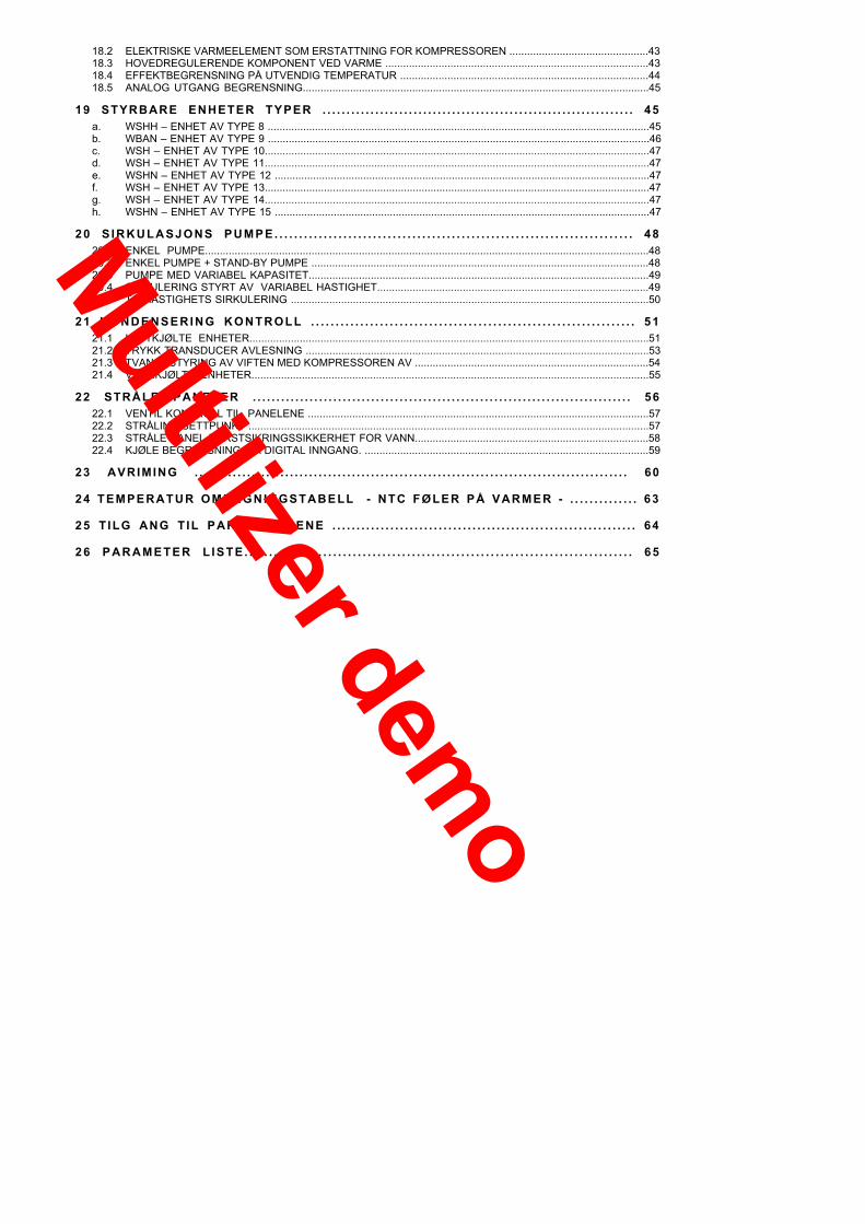
3 HOVED EGENSKAPER
Kontroll systemets hoved egenskaper:
• 1-kompressor styring
• kjøler/varme pumpe
• avkjølt luft eller vann
• fjern VARME - KJØLING omkobling
• fuktighetsføler (settpunkt korreksjon, entalpi avriming)
• vann reset (settpunkt forandring) mod. plug-in
• 2. settpunkt ( eco )
• VEDLIKEHOLD settpunkt (systemet innenfor arbeidsgrensene)• variabel settpunkt styring (forandres ved: utv. temperatur, entalpi, vann reset)
• variabel kompressor beskyttelse (kompensasjoner: last, pause styring, driftstid)
• variabel pumpe styring (reserve pumpe, variabel kapasitet)
• integrerte elektriske varmeelement mod. plug-in
• stråle paneler mod. Plug-in
• system kommunikasjon CLIVET TALK
• grensesnitt RS 485 mod. rs 485Noen av disse funsjoner er bare tilgjengelig ved installering av tilleggsmoduler..
3.1 VALGMULIGHETER
pacity OPT OPT OPT OPT OPT OPT2 speeds OPT OPT OPT OPT OPT OPT
Water differential pressure switch YES YES YES YES YES YES
Inl
Ex
M
w
M
et and outlet probe YES YES YES YES YES YES
Coil temperature probe - YES - YES - YES
ternal air temperature probe OPT YES OPT YES OPT YES
Pressure transducer OPT YES OPT YES OPT YESHumidity probe OPT OPT OPT OPT OPT OPTVentilation ON - OFF YES - YES - - -
ODULATING ventilation OPT YES OPT YES - -
Integrating electric heaters OPT OPT OPT OPT OPT OPTater reset OPT OPT OPT OPT OPT OPT
module RS 485 OPT OPT OPT OPT OPT OPTodulating external pump control OPT OPT OPT OPT OPT OPT
Radiating panels OPT OPT OPT OPT OPT OPT
YES YES YES YES YES
Multilizer demo

4 BLOKKSKJEMA OVER SYSTEMET MED TILLEGSFUNKSJONER
1CN2
12
11
10
9
8
765432
1
gnd
1CN1
21
20
19
18
17
16
15
14
13
+5v gnd
26
25
24
23
22
30
29
28
27
1CN3
OUT12 VDC
AC
DC
MAIN MODULEC5110760
CONV. MODULERS-485 C5110761
LOCAL KEYBOARDC5110766+C6541668
REMOTE KEYBOARDPE2N0001
max. 100 m
MODULE PWM- PHASECUT C5111026
PLUG-IN MODULEC5110767
4.1 PWM MODUL Æ FASE KUTT
Kode C5111026Denne modulen brukes til å styre kondenserings viften når denne trengs å styres (f.eks. varme pumpe).
AN
1A
N1
IIIIIIIAN1, AN1: PWM inn, tilført via terminal 13 og 15 på hoved modulen
I: Nettspenning inn 230 V ACDet må være samme fasen, som er tilkoblet transformatoren til hovedmodulen (med 12 V ac ut på CN 1, pin 1 og 2)
II, II, II: fase kutt utganger (3 i parallel) spenningstilførselen til vifta.
4.2 KONVERTER MODUL RS-485
KOD C5110761
Installert på hoved modulen for tilkobling til en ekstern serielllinje i RS485
Supplymodule 12 Vac
Serial lineRS-485
gnd+-
Multilizer demo

4.3 HOVED MODULKOD C5110766Modulen kontrollerer standard funksjonene; tilleggsfunksjonene styres av egne moduler.Figuren viser koblingen til en standard varme pumpe som, ulik kjøleren, har en trykkstyrt vifteregulator, som styrerhastigheten på kondenseringsvifta, føler for batteritemp. og utendørs temp..
.
1CN2
12
11
10
9
8
76
5
43
2
1
gnd
1CN1
212019181716151413
+5v gnd
BT6
BT3
BT1
BT2
C1
YV1
M4
BP1
230 v50 Hz
SP1
SP2
12 VacSQ1
SA3
SA2
SA1
FSC
RA BASIC MODULE
C1: kompressorYV1: 4veis ventilRA: Frostsikring varmeelementM4: Kondenserings vifteFSC: Vifte kontroll modulBP1: Trykk regulatorBT6: Utendørs lufttemp.følerBT3: Batteri temperatur følerBT2: Vanninntak temp.følerBT1: Vann utgangs temp.følerSP1: Høytrykk bryterSP2: Lavtrykk bryterSQ1: Strømningsbryter/Differensialtrykkbryter.SA1: Fjernstyrt PÅ-AVSA2: Fjernstyrt varme/kjølingSA3: Valg 2. settpunkt.
1
2
7
5
4
11
12
1
1211
109
87
65
43
21
CN2
gnd
6
116 mm
CN1
9
3
212019181716151413
8
91m
m
35791113
2468101214
135791113
24681214
15
16
+5V
Tx Rx
DTR
GN
D
8 KORT RESET STRAPTilkobling for firmware oppdatering via en ekstern programmerer: referansen “I“ indikerer hvordanprogrammeringskontakten skal tilkobles.9 RESET STRAPMå alltid være tilkoblet, både ved vanlig drift og under programmering.For å restarte modulen, ta ut strappen et kort øyeblikk.11 SERIELL TERMINERINGS STRAPDenne må være tilkoblet hvis “CANopen” seriell skal termineres; denne seiell, hvis brukt, er tilkoblet via pin19, 20og 21 (når en gateway brukes for å konvertere fra CANOPEN protokoll til en annen protokoll, for eksempel)12 PIN STRIP “TTL”Ikke i bruk på nåværende tidspunkt.
Multilizer demo

DIGITALE UTGANGER
( 1 ) KANTKONTAKTTerminal Beskrivelse Merknad
1 Nettspenning 230V2 Kompressor kontroll3 4 veis ventil kontroll / defrost at hot gas4 Integrasjon5 2° pumpe hastighet6 Frostsikring varmeelement kontroll7 Ekstern vifte /vannventil /kondenserings pumpe
RelèerMAKS 5 A (AC1) - 250V AC
( 2 ) KANTKONTAKT8 Fase inngang9 Fordamper pumpe kontroll 110 Fase inngang11 Kumulativ alarm signallering (NO)12 Kumulativ alarm signallering (NC)
MAKS 5 A (AC1) – 250 VAC
( 3 ) KANTKONTAKT DIVERSE13 Viftekontroll (PWM)14 Variabel pumpe kontroll (PWM)15 Felles referanse for (13) e (14)16 Tastatur strømforsyning (+12V - 2.5VA)17 Net (+Clivet Bus serial positiv)18 Gnd (-Clivet Bus serial negativ)19 GND – CAN OPEN serial20 L – CAN OPEN serial21 H – CAN OPEN serial
DIGITALE INNGANGER
( 6 ) MULTIPOLAR PLUGG CN1Pin Beskrivelse Merknad1 Kort strømforsyning2 Kort strømforsyning
12 VAC / 12 VDC
3 Kondensator strømning4 Lav trykk5 Begrensning kjøling6 Fase vakt7 Høy trykk8 Kompressor 1 sikkerhet + Vifte 1 sikkerhet9 Vann fylling system10 Ledig11 Inngang felles fra 1 til 1012 Fjernkontrollert PÅ-AV13 Fjernkontrollert Varme – Kjøling14 Valg av 2. settpunkt / ”Forespørsel” om varmt tappevann15 Strømningsbryter16 Inngang felles fra 12 til 15
Innganger isolert med OPTO-koblereSpenning 12 VAC eller12 V-15 VDC
ANALOGE INNGANGER UTGANGER
( 7 ) MULTIPOLAR PLUGG CN2Pin Beskrivelse Merknad1 Veksler vannutgangs temperatur2 Strålingspanel vann temperatur3 Veksler vann inngangs temperatur4 Krets 1 batteri temperatur5 Utgangs temperatur føler for elektrisk varmeelement6 Ekstern luft temperatur7 GND (jord) (Temperatur føler felles)
NTC 10 kilohm at 25 °C
8 Krets 1 trykk9 Ekstern RH%10 +12V (Trykkføler felles)
4-20 mA inn
11 -12 Analog utgang 0-10V (vifter / vann ventil)13 Analog utgang 0-10V (Pumpe inverter)14 Analoge utganger felles
0-10 V ut
Multilizer demo

4.4 �PLUG-IN� EKSPANSJON MODUL
KOD C5110767
Er plassert over hoved modulen for å kontrollere tilleggsfunksjonene:• Integrerte varmeelement ( side 35 )• vann reset ( side 27 )• strålingspaneler ( side 48 )
13
14
2625
2423
2230
2928
27
CN3
1357911
24681012
15
( 13 ) ANALOGE SIGNALER
UTGANGERPIN Beskrivelse Merknader1 Ledig2 Ledig3 Integrasjon4 Stålingpaneler ventil5 Proporsjonal kompressor styring6 Gnd (Jord)felles for utgang fra 1 til 5 og (12)
0-10 V
INNGANGERPIN Beskrivelse Merknader7 Vann reset8 Ledig / WBAN trykk føler9 +12V positiv strømforsyning(7), (8) e (11) INN 4-20 mA
10 Ledig11 Inngang 0-10V (Ikke i bruk)12 Ikke i bruk ikke kontrollerte innganger
DIGITALE UTGANGER
( 14 ) AVTAGBART TERMINAL KORTTerminal Beskrivelse Merknader22 Nettspenning 230V23 Strålingspaneler ventil 124 Strålingspaneler pumpeventil25 Strålingspaneler ventil 226 Varmt tappevann ventil kontroll
5 A 250 VAC
( 15 ) AVTAGBART TERMINAL KORTTerminal Beskrivelse Merknader27 Nettspenning28 Vanninntak solenoid ventil for varme pumpe29 Nettspenning30 Vannutgangs solenoid ventil for varme pumpe
5 A 250 VAC
Multilizer demo
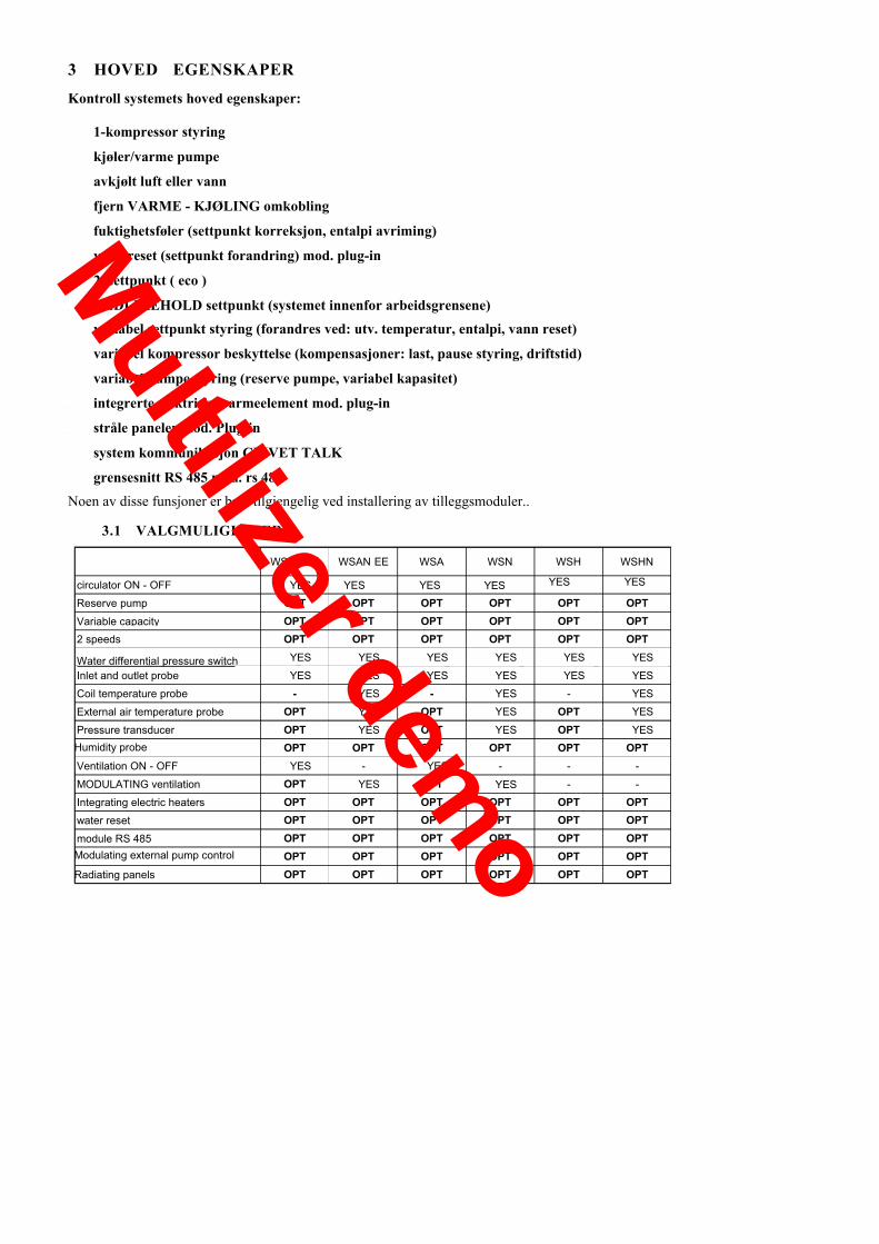
4.5 LED TASTATURKNAPP FUNKSJON
LED INDIKASJON
VINTER funksj.
VARME
KJØLING
1.1.1.1 PÅ / AVLANGT trykk
KOMFORT modus
LED funksjonstest
ØKONOMI modus2° settpunkt
1° settpunkt
ELEKTRISKkrets alarm
KULDEMEDIUMkrets alarm SOMMER funksj.
VANN kretsalarm
enhet PÅ / AV /VEDLIKEHOLD (Blinker)
På tastaturet, kan du se, og forandre funksjonene til enheten.Service tastaturet trengs for å vise, og oppdatere funksjonsparameterene.
PÅ - AV
PÅ � AV funksjonen på tastaturet, aktiverer og deaktiverer enhetens normale funksjoner.
INNSTILLING AV ARBEIDS MODUS
KJØLING: for å stille inn SOMMER modus, trykk knappen, og hold den inne en liten stund.Når den er blitt aktivert, lyser tilsvarende grønne LED.
VARME: for å aktivere VINTER modus, trykk knappen, og hold den inne en liten stund.Når den er blitt aktivert, lyser tilsvarende grønne LED.
VEDLIKEHOLD: Den grønne LEDen som indikerer driftsmodus, fortsetter å lyse, selv om maskinen er i vedlikehold modus.Vedlikehold settpunktet (hvis aktivert) kontrollerer vann temperaturen når enheten er AV eller i STANDBY. For å gjøre dette,blir sirkulasjonspumpen aktivert periodisk, slik at vanntemperaturen kan sjekkes, og kompressoren starter, hvis nødvendig..
VALG AV ARBEIDS TEMPERATUR
KOMFORT: for å velge KOMFORT temperatur for gjeldende arbeidsmodus, trykk KOMFORT knappen. Settpunktet visesbare på maskinen.Når denne modusen er aktivert,, vil LEDen til venstre for knappen tennes, og være tent.
ECO: for å velge ØKONOMI temperatur for gjeldende arbeidsmodus, trykk ECO knappen.Settpunktet reduseres i vinterdrift, og økes i sommerdrift.Når denne modusen er aktivert, vil den grønne LEDen til venstre for knappen, blinke sakte.
SIGNALLERING AV PRODUKSJON AV VARMT TAPPEVANN
VARME modus +vinter modus +Fremstilling av varmt tappevann Blinker på
VARME modus +sommer modus + På blinker
Multilizer demo

ALARMER
BLINKENDE LED: det er en uregelmessighet med AUTOMATISK reset
FAST LYSENDE LED: det er en uregelmessighet med MANUAL reset
ALARM RESET: TEST + ON/OFF knapper trykkes samtidig i mer enn 2 sekunder
Alarm type:
ELECTRISK KRETS ALARM KJØLE KRETS ALARM VANN KRETS ALARM
Inngangs føler HP StrømningspumpeUtgangsføler LP Vannfylt systemStrålingspanel vannføler CCMP/VENT Frostsikrings alarmBatter/strømnings føler HP1 Pre-Alarm Frostsikring FORAlarmEkstern føler BP1 Pre-Alarm Pumpe alarmTrykk 1 føler C1 FORAlarmVann reset inngang PRad. Kjølebegrensning alarmEkstern føler for relativ fuktighet PRad. Vann frost alarmFase monitor Batteri frost alarmVarmeelement utgangs føler Alarm ?T° inkongruentPlug-in trykk føler (WBAN) Varmeelement frostsikring alarm
FUNKSJONS TEST
�Test� bekrefter at alle 6 LEDen fungerer tilfredsstillende.Når den er trykket inn, lyser alle LEDene, helt til knappen slippes.
FIRMWARE VERSJON INDIKERINGTastaturets firmware versjon står på en merkelapp på innsiden av LED tastaturet .
Multilizer demo

4.6 TASTATUR
KOD C 5110799 ( tastatur ) + C6541668 (silk-screen print )For tastaturets bruker modus, se: set modifikasjon, side. 16, alarmer side 18. , statuser side. 17, passord side. 56I noen serier/størrelser kan ikke tastaturet monteres.In this case, the following controls are given through external arranged by the customer:
REMOTE ON- OFF , HEAT � COOL , SECONDARY Set pointDet nye UNIFIED C5110799 tastaturet tilpasser seg automatisk basis firmwaren, slik at det ikke er nødvendig åprogrammere den for hver type enhet.Den kan også ta seg av ALARMER, alvorlige varslet med den vanlige E�. , og SIGNALLERING, mindre alvorligmed C� eller S�.
Tasto + led Raffreddamento
Tasto + led Riscaldamento
Indeks Dispaly Verdi Display
Når LEDen lyser, må avlest verdiPå displayet ganges 100
enu parametri
T indici
-Off
Avri di stato dello 1
Led di stato del compresso
Tasto per ingresso nel m
asti per scorrimento
Tasto di On
ta valoristi per incremento e decremento dei
tasto per ingresso nel menù e nello sorico allarmi
Tasto per ingresso nel menu Stati
re 1
pompa
Defrosting status led 1
Compressor 1 status led
Led di stato dellaPump status led
Led ON-OFF: Lyser bare hvis enheten er påslått.
Led HEAT: Lyser når enheten er i VARME modus, også hvis enheten er AV
Led COOL: Lyser når enheten er i KJØLE modus, også hvis enheten er AV
Led SET : Lyser når PARAMETER SETTING menyen er aktiv
Led STATUS : Lyser når ENHETENS STATUS meny er aktiv
Led ALARM : Lyser bare i ALARM LOG menyen, blinker ved alarm.
Led �Defrosting status 1�: lyser når avriming pågår, blinker for timerstyrt avriming
Led �Compressor status 1�: lyser når kompressoren er PÅ, blinker for timerstyring
Led �Pump status�: Lyser når pumpa går.Led �multiplier by 100�: Når den lyser, må avlest verdi i displayet ganges med 100.
Led ON-OFF: Lyser bare når enheten er PÅ.
Index scrolling key
Key for value increase or decrease
Key + led heating
Key + led Cooling
Parameter menu inlet key
Menu and log alarms inlet key
Status menu inlet key
On-off key
Multilizer demo

Led HEAT: Lyser når enheten er i VARME modus også når enheten erAV
Led COOL: Lyser når enheten er i KJØLE modus også når enheten erAV
Led SET : Lyser når PARAMETER SETTING menyen ier aktive
Led STATUS : Lyser når ENHETENS STATUS meny er aktive
Led ALARM : Lyser bare i ALARM LOG menyen, blinker vedalarm..Led �Defrosting status 1�: lyser når avriming pågår, blinker for
timerstyrt avriming
Led �Compressor status 1�: lyser når kompressoren er PÅ, blinker fortimerstyring
Led �Pump status�: Lyser når pumpa går.
Led �multiplier by 100�: Når den lyser, må avlest verdi i displayetganges med 100.
Multilizer demo

4.7 REMOTE KEYBOARD
COD C5110799 (keyboard code only)
The figure shows the connections of the local keyboard (if installed) and of the remote keyboard (optional).The two keyboards work in parallel and practically perform the same functions.
After having supplied each keyboard, assign the relevant address within the network.Keyboard address on the Clivet Bus network: Par 207 = 7 keyboard on machine
= 1 remote keyboard
If the unit is equipped with a led keypad rather than with a keypad with 7 segments ( C5110776 ) , the remotekeypad must have address 7.
Connection with the remote keyboard:• shielded and twisted cable 2 x 0.35 mm2, max. 100 m• installed according with the relevant norms (electric systems)• laid within a dedicated raceway and far from power cables .
Terminals on the keyboard seen from the rear:1 e 2 For the keyboard standard operation the two jumpers must be off
to change the firmware bridge the two jumpers.3 connector to be used to change the firmware (connection with the flash programmer�
eeprom ) .
212019181716151413
+5V TxRxR N
DTG
D
1
23
gnd
NET
+12V+12V
gnd
+12V
gnd
F N PE230 VAC
MA
X 10
0 m
2x0.
35m
m
2
twis
ted
and
shie
lded
UNIT1
23
gnd
+12V+12V
gnd
NET
PE2N0001
Multilizer demo

5 CONNECTIONS TO THE CUSTOMER CARE
REMOTE ON-OFF :remote switching on and off of the unitcompulsory connection on the units without keyboardalways enabled, not linked with par 163 Remote input configurationconnections on basic module, CN1 pin 12 e 16
REMOTE HEAT-COOL :switching from summer to winter mode and vice versacompulsory connection on the units without keyboardenabled only if par 163 Remote input configuration = 0connections on basic module, CN1 pin 13 and 16
SECONDARY SET-POINT :enabling of a second set-pointusually higher in summer and lower in winter than the standard set-point.enabled only if par 163 Remote input configuration = 0connections on base module, CN1 pin 14 and 16
par 29 Summer secondary set-point 10 °Cpar 30 Winter secondary SetPoint 35 °Cpar 31 Enable second Set 0 num
EXTERNAL AIR TEMPERATURE PROBE :see the paragraph on Ext. temperature correction on page Feil! Bokmerke er ikke definert.4connections on basic module, CN2 pin 6 e 7
SONDA UMIDITÀ ARIA ESTERNA :see the paragraph on Ext. temperature correction on page 306connections on basic module, CN 2 pin 9 and 10
WATER RESET :see the relevant paragraph page 317connections on optional plug-in module, CN3 pin 7 and 9
REMOTE KEYBOARD :connections on base module, removable term. 16 17 18
RADIATING PANELS :See the relevant paragraph on pag 48The following connections are required for this function:Temp. probe. (connections on basic module CN2 pin 2 and 7 )Valve (connection on optional module on page 10)Pump (connections on optional plug-in module on page 10)Cooling limit (connections on base module, CN1 pin 5 and 11)
Multilizer demo

6 START AV ENHETEN
Enhet i AV status:• Fra tastatur• Fra FJERN PÅ/AV kontakt
PÅSLAG:FORLENGET trykk avPÅ-AV KNAPPEN
Visning avUTKOBLING TEMPERATUR
7 FORANDRING AV SETTPUNKT
Trykk knappen SET
For å komme til ønsket verdi:trykk PIL OPP - NED
Vent 2 sekunder
PARAMETERVERDIEN vises
Justere parameterverdien:
knappene + e -For å komme til andre parametere:
trykk PIL OPP - NED
For å avslutte:knappen SET
OF F
OF F
11. 6
11. 6
0 0
2 9 - - - -
2 9 1 0. 0
2 9 1 0. 0
3 0
11. 6Multilizer dem
o
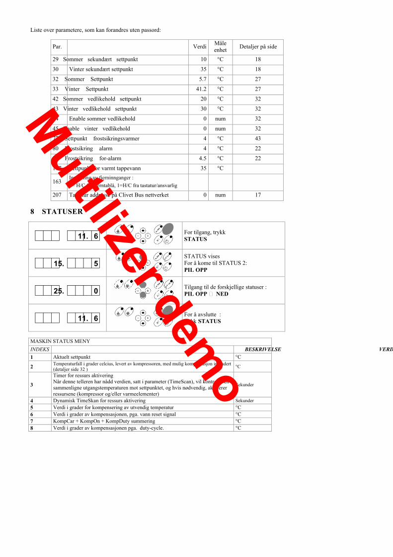
Liste over parametere, som kan forandres uten passord:
Par. Verdi Måleenhet Detaljer på side
29 Sommer sekundært settpunkt 10 °C 18
30 Vinter sekundært settpunkt 35 °C 18
32 Sommer Settpunkt 5.7 °C 27
33 Vinter Settpunkt 41.2 °C 27
42 Sommer vedlikehold settpunkt 20 °C 32
43 Vinter vedlikehold settpunkt 30 °C 32
44 Enable sommer vedlikehold 0 num 32
45 Enable vinter vedlikehold 0 num 32
77 Settpunkt frostsikringsvarmer 4 °C 43
80 Frostsikring alarm 4 °C 22
84 Frostsikring for-alarm 4.5 °C 22
117 Settpunkt for varmt tappevann 35 °C
163Innstilling av fjerninnganger :0= H/C fra fjerntablå, 1=H/C fra tastatur/ansvarlig
207 Tastatur addresse på Clivet Bus nettverket 0 num 17
8 STATUSER
For tilgang, trykkSTATUS
STATUS visesFor å kome til STATUS 2:PIL OPP
11. 6
15. 5
Tilgang til de forskjellige statuser :PIL OPP � NED
For å avslutte :trykk STATUS
25. 0
11. 6
MASKIN STATUS MENYINDEKS BESKRIVELSE VERDI1 Aktuelt settpunkt °C
2 Temperaturfall i grader celcius, levert av kompressoren, med mulig kompensasjon inkludert(detaljer side 32 ) °C
3
Timer for ressurs aktiveringNår denne telleren har nådd verdien, satt i parameter (TimeScan), vil kontrollerensammenligne utgangstemperaturen mot settpunktet, og hvis nødvendig, aktivererressursene (kompressor og/eller varmeelementer)
Sekunder
4 Dynamisk TimeSkan for ressurs aktivering Sekunder5 Verdi i grader for kompensering av utvendig temperatur °C6 Verdi i grader av kompensasjonen, pga. vann reset signal °C7 KompCar + KompOn + KompDuty summering °C8 Verdi i grader av kompensasjonen pga. duty-cycle. °C
Multilizer demo

MASKIN STATUS MENYINDEKS BESKRIVELSE VERDI9 Inngangs temperatur °C10 Utgangs temperatur °C11 Vanntemperatur på strålings panelene °C12 Batteri temperatur °C13 Kondenseringstrykk Bar14 Prosentvis Vifte/Ventil 1 0-100%15 Varmeelement utgangstemperatur °C16 WBAN kondenseringstrykk Bar17 Modulerende kompressor utgangsstatus %18 Vannreset signal verdi 4-20 mA19 Utvendig temperatur °C20 Utvendig fuktighet 0-100%21 �Unit watch� ( kun enhetens driftstimer ) Num22 Driftstimer C1 Num23 Starter C1 Num24 Strålingspanel ventil status ON-OFF25 Strålingspanel ventil status %26 Pumpe prosentandel %27 Integration heaters status ON-OFF28 Radiating panel valve status (Out-1) ON-OFF29 Radiant set point °C30 Tastatur programvare EJ � t ( ELFO31 Validation year of keyboard SW 200632 Validation month of keyboard SW 0733 Validation day of keyboard SW 2034 Base Software EJ � b (ELFO35 Validation year of base SW 200636 Validation month of base SW 0737 Validation day of base SW 21
9 ALARMER
BLINKINGalarm kodeenhetens driftstimer ved hendelsen
KORT trykk på knappen ALARMGir tilgang til ALARM LOGGENDen ALLER SISTE alarmen vises
For å sjekke alarmer i loggen:PIL NED
KORT trykk på knappen ALARM:Går ut av alarmloggen
For å NULLSTILLE alarmene:LANGT trykk på knappen ALARM
E11 2
E11 2
E11 2
E17 2
E11 2
Multilizer demo

INDEX ALARM RESET
1 E Defekt, eller frakoblet føler på vanninngangen Auto.
2 E Defekt, eller frakoblet føler på vannutgangen Auto.
3 E Defekt, eller frakoblet vannføler på strålingspanelet (strålingspanel option) Auto.
4 E Defekt, eller frakobler føler på batteriet Auto.
5 E Elektrisk varmeelement utgangsføler Auto
6 E Defekt, eller frakoblet ekstern føler Auto.
7 E Defekt, eller frakoblet trykk transducer Auto.
8 E WBAN plug-in trykkføler Auto
9 S Vannreset inngang kortsluttet, eller ute av området Auto.
10 E Defekt, eller frakoblet RH% føler Auto.
11 E Høytrykk MANUAL
12 E Lavtrykk Auto.
13 E Kondenseringsvifte og/eller kompressor termisk bryter MANUAL
14 E Varmeelement frostsikrings alarm MANUAL
17 E Strømningspumpe Auto.
18 E Lavtrykk på vann rørsystemet MANUAL
19 E Fase monitor Auto.
20 E Frostsikring alarm MANUAL
21 S Frostsikring FORAlarm Auto.
22 S Høytrykk ForAlarm Auto.
24 S Pumpe bytte (system med hoved pumpe og stand-by pumpe) Auto.
25 E Kondensator strømningsalarm (differensial trykkbryter, kun vannkjølte enheter) Auto.
30 E Batteri ising alarm MANUAL
31 E Kjøling / Varme begrensning alarm (strålingspanel option) Auto.
32 E Vann frost alarm (strålingspanel option) Auto.
33 E Inkongruent deltaT alarm MANUAL
34 S / E BP1 for-alarm Auto.
9.1 SLETTING AV ALARMLOGG
Et passord (= 101), bekreftes ved å trykke �pil opp�, sletter alarm loggen, og nullstiller maskin klokken (detaljer side 56)
Multilizer demo
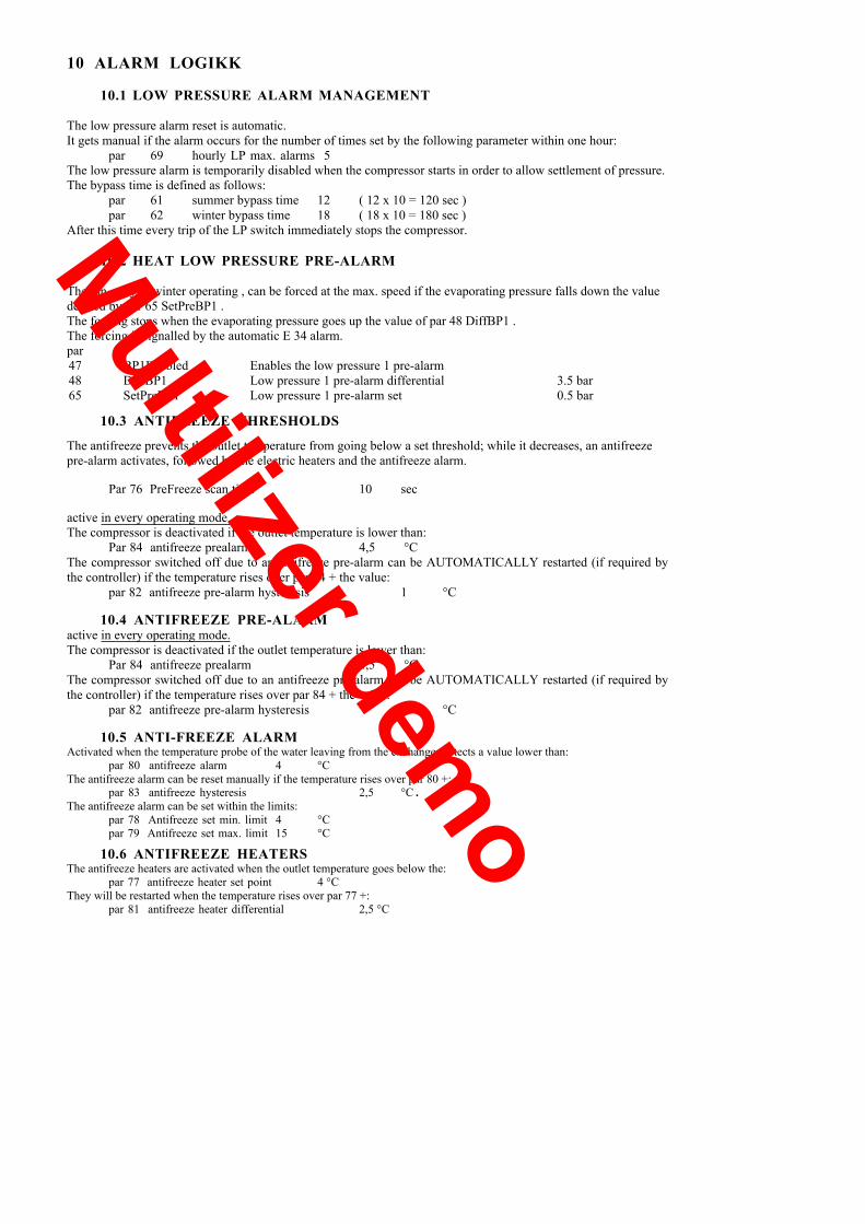
10 ALARM LOGIKK
10.1 LOW PRESSURE ALARM MANAGEMENT
The low pressure alarm reset is automatic.It gets manual if the alarm occurs for the number of times set by the following parameter within one hour:
par 69 hourly LP max. alarms 5The low pressure alarm is temporarily disabled when the compressor starts in order to allow settlement of pressure.The bypass time is defined as follows:
par 61 summer bypass time 12 ( 12 x 10 = 120 sec )par 62 winter bypass time 18 ( 18 x 10 = 180 sec )
After this time every trip of the LP switch immediately stops the compressor.
10.2 HEAT LOW PRESSURE PRE-ALARM
The fan, only in winter operating , can be forced at the max. speed if the evaporating pressure falls down the valuedefined by par 65 SetPreBP1 .The forcing stops when the evaporating pressure goes up the value of par 48 DiffBP1 .The forcing is signalled by the automatic E 34 alarm.par47 BP1Enabled Enables the low pressure 1 pre-alarm48 DiffBP1 Low pressure 1 pre-alarm differential 3.5 bar65 SetPreBP1 Low pressure 1 pre-alarm set 0.5 bar
10.3 ANTIFREEZE THRESHOLDS
The antifreeze prevents the outlet temperature from going below a set threshold; while it decreases, an antifreezepre-alarm activates, followed by the electric heaters and the antifreeze alarm.
Par 76 PreFreeze scan time 10 sec
active in every operating mode.The compressor is deactivated if the outlet temperature is lower than:
Par 84 antifreeze prealarm 4,5 °CThe compressor switched off due to an antifreeze pre-alarm can be AUTOMATICALLY restarted (if required bythe controller) if the temperature rises over par 84 + the value:
par 82 antifreeze pre-alarm hysteresis 1 °C
10.4 ANTIFREEZE PRE-ALARMactive in every operating mode.The compressor is deactivated if the outlet temperature is lower than:
Par 84 antifreeze prealarm 4,5 °CThe compressor switched off due to an antifreeze pre-alarm can be AUTOMATICALLY restarted (if required bythe controller) if the temperature rises over par 84 + the value:
par 82 antifreeze pre-alarm hysteresis 1 °C
10.5 ANTI-FREEZE ALARMActivated when the temperature probe of the water leaving from the exchanger detects a value lower than:
par 80 antifreeze alarm 4 °CThe antifreeze alarm can be reset manually if the temperature rises over par 80 +:
par 83 antifreeze hysteresis 2,5 °C .The antifreeze alarm can be set within the limits:
par 78 Antifreeze set min. limit 4 °Cpar 79 Antifreeze set max. limit 15 °C
10.6 ANTIFREEZE HEATERSThe antifreeze heaters are activated when the outlet temperature goes below the:
par 77 antifreeze heater set point 4 °CThey will be restarted when the temperature rises over par 77 +:
par 81 antifreeze heater differential 2,5 °C
Multilizer demo
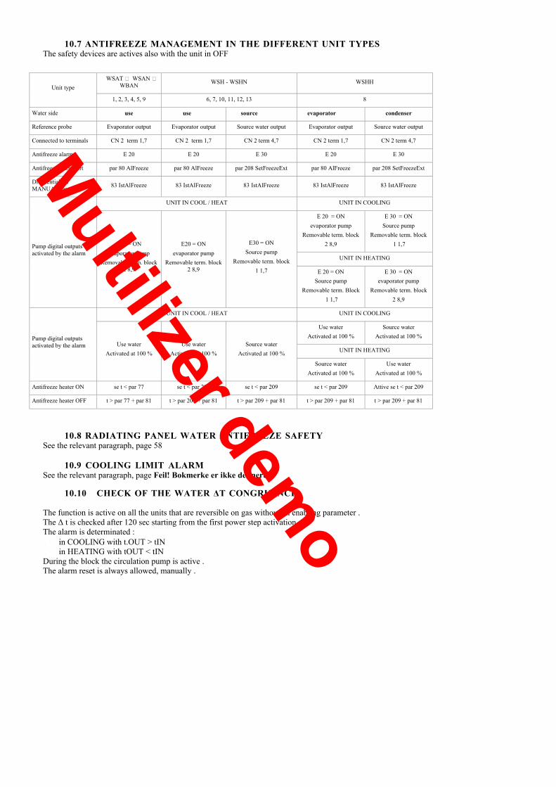
10.7 ANTIFREEZE MANAGEMENT IN THE DIFFERENT UNIT TYPESThe safety devices are actives also with the unit in OFF
WSAT � WSAN �WBAN WSH - WSHN WSHH
Unit type
1, 2, 3, 4, 5, 9 6, 7, 10, 11, 12, 13 8
Water side use use source evaporator condenser
Reference probe Evaporator output Evaporator output Source water output Evaporator output Source water output
Connected to terminals CN 2 term 1,7 CN 2 term 1,7 CN 2 term 4,7 CN 2 term 1,7 CN 2 term 4,7
Antifreeze alarm E 20 E 20 E 30 E 20 E 30
Antifreeze alarm sert par 80 AlFreeze par 80 AlFreeze par 208 SetFreezeExt par 80 AlFreeze par 208 SetFreezeExt
Differential forMANUAL reset 83 IstAlFreeze 83 IstAlFreeze 83 IstAlFreeze 83 IstAlFreeze 83 IstAlFreeze
UNIT IN COOL / HEAT UNIT IN COOLING
E 20 = ONevaporator pump
Removable term. block2 8,9
E 30 = ONSource pump
Removable term. block1 1,7
UNIT IN HEATING
Pump digital outputsactivated by the alarm
E20 = ONevaporator pump
Removable term. block2 8,9
E20 = ONevaporator pump
Removable term. block2 8,9
E30 = ONSource pump
Removable term. block1 1,7 E 20 = ON
Source pumpRemovable term. Block
1 1,7
E 30 = ONevaporator pump
Removable term. block2 8,9
UNIT IN COOL / HEAT UNIT IN COOLING
Use waterActivated at 100 %
Source waterActivated at 100 %
UNIT IN HEATING
Pump digital outputsactivated by the alarm Use water
Activated at 100 %Use water
Activated at 100 %Source water
Activated at 100 %
Source waterActivated at 100 %
Use waterActivated at 100 %
Antifreeze heater ON se t < par 77 se t < par 209 se t < par 209 se t < par 209 Attive se t < par 209
Antifreeze heater OFF t > par 77 + par 81 t > par 209 + par 81 t > par 209 + par 81 t > par 209 + par 81 t > par 209 + par 81
10.8 RADIATING PANEL WATER ANTIFREEZE SAFETYSee the relevant paragraph, page 58
10.9 COOLING LIMIT ALARMSee the relevant paragraph, page Feil! Bokmerke er ikke definert.
10.10 CHECK OF THE WATER ΔT CONGRUENCE
The function is active on all the units that are reversible on gas without an enabling parameter .The Δ t is checked after 120 sec starting from the first power step activation .The alarm is determinated :• in COOLING with t.OUT > tIN• in HEATING with tOUT < tIN
During the block the circulation pump is active .The alarm reset is always allowed, manually .
Multilizer demo

MAX. VENTILATION - HP1 COOL PREALARM
The fan speed control logic is explained on page45:
In the units including this option, it is possible to enable a pressure threshold over which the fan is forced to themax. speed. To prevent stop due to high pressure.
Par 111 Enable HP1 prealarm 0
the fan sets to the max. silenced speed, equal to 100% the max. applicable voltage if during the operation thecondensing pressure rises over the value:
par 112 set summer HP1 prealarm 25 bar
goes back to 80% when the pressure lowers to the value par 112�par 113 delta summer HP1 prealarm 2 bar
A log alarm signal is expected when condensing pressure goes over par 112 .
FLOW ALARM MANAGEMENT
The management referred to a unit configured with single pump + stand-by pump is shown as example .
UNITSTART
THE PILOT PUMPSTOPS AND THE
STAND-BYONE STARTS
UNIT' ONPUMP ON
COUNTING START 25 SEC(flow bypass time= par
142 )
ELAPSED 25 SEC(flow bypass time = par 142 )
CLOSED FLOWSWITCH ?
Yes
THE PUMP STILLOPERATE NORMALLY
THE COMPRESSOR STOPSSIGNALLING PUMP STILL OPERATING
FOR 120 SEC.( par 145 )
THE FLOW ALARM ISRECOVERED BEFORE THE TIME
HAS ELAPESD 120 sec
PUMP STOPFLOW ALARM SIGNAL
RESTART BY MANUALRESET ONLY
COMPRESSOR HAS BEENSTARTED
ELAPSED 25 SEC ?(compressor start delay time=
par 143 )
Yes
No
No
FAULT ON WATER FLOW
Yes
No
A TRIAL WITHTHE
STAND-BY PUMP HASBEEN MADE ALREADY
Yes
No
FLOW ALARM MANAGEMENT WITH WATER CONDENSATIONWINTER : the alarm is bypassed for the time par 107 TimeOffV from the condenser pump startingSUMMER : the alarm is bypassed for the time par 107 TimeOffV from the evaporator pump starting
Multilizer demo

11 MANAGEABLE SYSTEM OPTIONS
The system can manage le following options (all at the same time, only one or two by choice):• heating integrative element (heaters or boiler, details on page 35)• 3-way valve for sanitary water• double temperature � radiant panels (details on page 48)
Below is an indicative diagram with all options.
UNIT� RADIANTS INSTALLATION
YVR
T IN
T Ext
T. RadOn-Off /
0-10V
T OUT
FAN COIL
BOILER
HYDRAULIC MODULEHEATING INTEGRATION 3-WAY VALVE
11.1 WAY VALVE MANAGEMENT FOR SANITARY WATER
By par 50 = 1 the input of the 2° set point on the main board is configured as SANITARY WATER REQUEST.It is possible to manage a 3-way valve for the sanitary hot water production by a dedicated set point (par 117)It is necessary the expansion plug-in module that must be enabled by parameter 140 = 1 .
MODEINPUT
2° set point on themain board
VALVE POS. SET POINT 2° SET POINT
HEATING ON to the installation set HEAT 2° setpoint heat *
SANITARY WATER OFF to the boiler SetH2OSanitaria not manageable
ON to the installation set cool 2° setpoint cool *COOLING
OFF to the installation set cool 2° setpoint cool *
* enable : from led keypad or setting the par 49 =1
Par Description Meaning value
49 Comando2°Set Mode control 2° set point by parameter 0
50 EnH2OSanitaria Enabling sanitary water valve management 0
117 SetH2OSanitaria Set Point sanitary water 35
140 PlugInEn Enables the PLUG-IN presence. 1=YES / 0=NO
The setH2Osanitaria is not loaded of the different compensations and corrections ; only the relative compensationis in case active at the external temperature limit ( par 73 , see page 30 )
Multilizer demo

12 SET-POINT MANAGEMENT
The controller uses two set-points, one for summer and for winter
Par 32 Summer Set Point def = 5.7 °CPar 33 Winter Set Point def = 41.2 °C
In both cases the set-point is automatically limited within the max. and min. limits defined byPar 25 MAX Set Heat def = 51 °CPar 26 Min Set Heat def =22 °CPar 27 Max Set Cool def = 21 °CPar 28 Min Set Cool def = 5 °C
12.1 CORRECTIONS ON SET-POINT
The corrections are aimed at optimising the unit energy efficiency.
To achieve this, the corrections modify the set-point dynamically according to certain variables. For example, inthe summer operation with low external temperatures, thus with reduced load, it is possible to obtain an indoorcomfort with set-points even higher than the standard, thus with a higher energy efficiency
Correct Set Point (es 6.7 °C)
The static set-point can be modified dynamically with two CORRECTIONS based on as many
factors external to the unit:
• correction based on the external temperature/enthalpy
• correction based on the Water reset (signal 4-20 mA supplied by the customer)
The correct set-point, to which all corrections have been added or subtracted, is identified asACTUAL set-point and is displayed by the status n°1 ( see page 20 )
12.1.1 CORRECTION ON THE EXTERNAL TEMPERATURE
This function can be activated on the chillers only if the external air probe BT6 is installed (basic module, CN2 pin6 and 7)
Par 152 EXT. air probe presence 1 numPar 9 Comp. enabling for external temperature = 0 no compensation
1 compensates in summermode only
2 compensates in wintermode only
CORRECTION
ACTUAL Set pointor right ( state n° 1 )
correction
Set Point (es 5.7 °C)
Summer/Winter Set Point
Slettet:
Slettet:
Slettet:
Summer/Winter
Summer/Winter
Multilizer demo

SUMMERIn the summer operation with low external temperatures a reduced cooling demand is supposed.Thus, the indoor confort can be obtained even with set-points higher than the standard.In the summer operation, the correction is added to the set-point (thus it is increased while external temperaturedecreases. )
The max. value of the correction that can be applied is set by:Par 14 Max. value of summer correction 6 °C
The correction is active in the temperature range defined by:Par 10 External temperature for max. summer correction 15 °CPar 11 External temperature for min. summer correction 30 °C
This function can be used also with a different logic: increase the set-point while the external temperatureincreases.In this case, the required operation is opposite the previous one; the set values are thus reversed:
Par 10 External temperature for max. summer correction 30 °CPar 11 External temperature for min. summer correction 15 °C
WINTER
In the winter mode with mild external temperatures (e.g. 15°C) the thermal requirement is supposed low and thusthe room comfort can be reached with a lower set-point, too.The correction is thus subtracted from the set-point (thus it is decreased while the external temperature increases )
ACTUAL set-point
Correction Max. Value= par 15
correction
Max correction =par 14
External Temp.Par 10 par 11
correction
ACTUAL set-point
External Temp.
Par 13 par 12
The max. value of the correction that can be applied is set by:Par 15 Max. value of winter correction 10 °C
The correction is active in the temperature range defined by:Par 12 External temperature for max. winter correction 15 °CPar 13 External temperature for min. winter correction -5 °C
The above remarks apply here, too: the function can be used with a different logic:decrease the set-point while the external temperature decreases.The required operation is opposite the previous one; the set values are thus reversed.
Par 12 External temperature for max. winter correction -5 °CPar 13 External temperature for min. winter correction 15 °C
Multilizer demo

MAX correction
CORRECTION ON THE EXTERNAL TEMPERATURE FOR COMPRESSOR OPERATING LIMITThis function allows to extend the operating limit lowering the setpoint when the external temperature decreases
par 73 enables correction for the ext temp limit 1=YESpar 74 external temperature for max heat setpoint - 2 °Cpar 160 external temperature for min heat setpoint -15 °Cpar 175 min value settable of the heat setpoint 35 °C
Enabling both the correction for the external temperature ( curve A ) and the correction for limit ( curve B ) , thecorrect setpoint has this performance :
12.1.2 CORRECTION ON ENTHALPYThe function can be activated only if the expansion PLUG-IN module and the humidity probe areinstalled.The enthalpy correction is active in the summer operation; in the winter operation the correction isapplied only on the external air dry bulb temperature (enthalpy value is not active).The logic is the previously described one: the lower the humidity content in the air, the lower the coolingdemand thus the set-point can be increased (compensated)
Par 14 Max. value of summer correction 6 °CPar 16 External enthalpy min. correction 10.5 °CPar 17 External enthalpy max. correction 13.5 °CPar 156 Enable external RH% probe 0 num
Par 14 = 6 °C
set point
correzionepar 16 par 17= 10.5 = 13.5 temp b.u. °C
SET POINT
COMP.= 0COMP.
MAX
P175
Text °cP 74P 160
SET POINT40 °C
37 °C
35 °C
T EXT15°C7 °C
AB
-2 °C-15 °C
Slettet: Correzione MASSIMA
Multilizer demo
summer correction
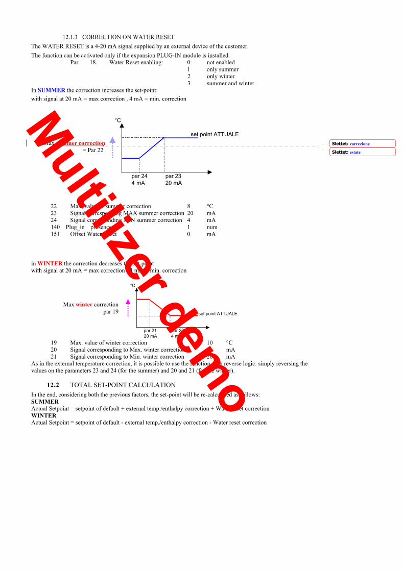
12.1.3 CORRECTION ON WATER RESETThe WATER RESET is a 4-20 mA signal supplied by an external device of the customer.The function can be activated only if the expansion PLUG-IN module is installed.
Par 18 Water Reset enabling: 0 not enabled1 only summer2 only winter3 summer and winter
In SUMMER the correction increases the set-point:with signal at 20 mA = max correction , 4 mA = min. correction
°C
set point ATTUALE
22 Max. value of summer correction 8 °C23 Signal corresponding MAX summer correction 20 mA24 Signal corresponding MIN summer correction 4 mA140 Plug_in presence 1 num151 Offset Water Reset 0 mA
in WINTER the correction decreases the set-pointwith signal at 20 mA = max correction , 4 mA = min. correction
19 Max. value of winter correction 10 °C20 Signal corresponding to Max. winter correction 4 mA21 Signal corresponding to Min. winter correction 20 mA
As in the external temperature correction, it is possible to use the function with reverse logic: simply reversing thevalues on the parameters 23 and 24 (for the summer) and 20 and 21 (for the winter).
12.2 TOTAL SET-POINT CALCULATIONIn the end, considering both the previous factors, the set-point will be re-calculated as follows:SUMMERActual Setpoint = setpoint of default + external temp./enthalpy correction + Water reset correctionWINTERActual Setpoint = setpoint of default - external temp./enthalpy correction - Water reset correction
Max= Par 22
°C
set point ATTUALE
par 21 par 2020 mA 4 mA
par 24 par 234 mA 20 mA
Slettet:
Slettet:
correzione
estate
Max winter correction= par 19
Multilizer demo
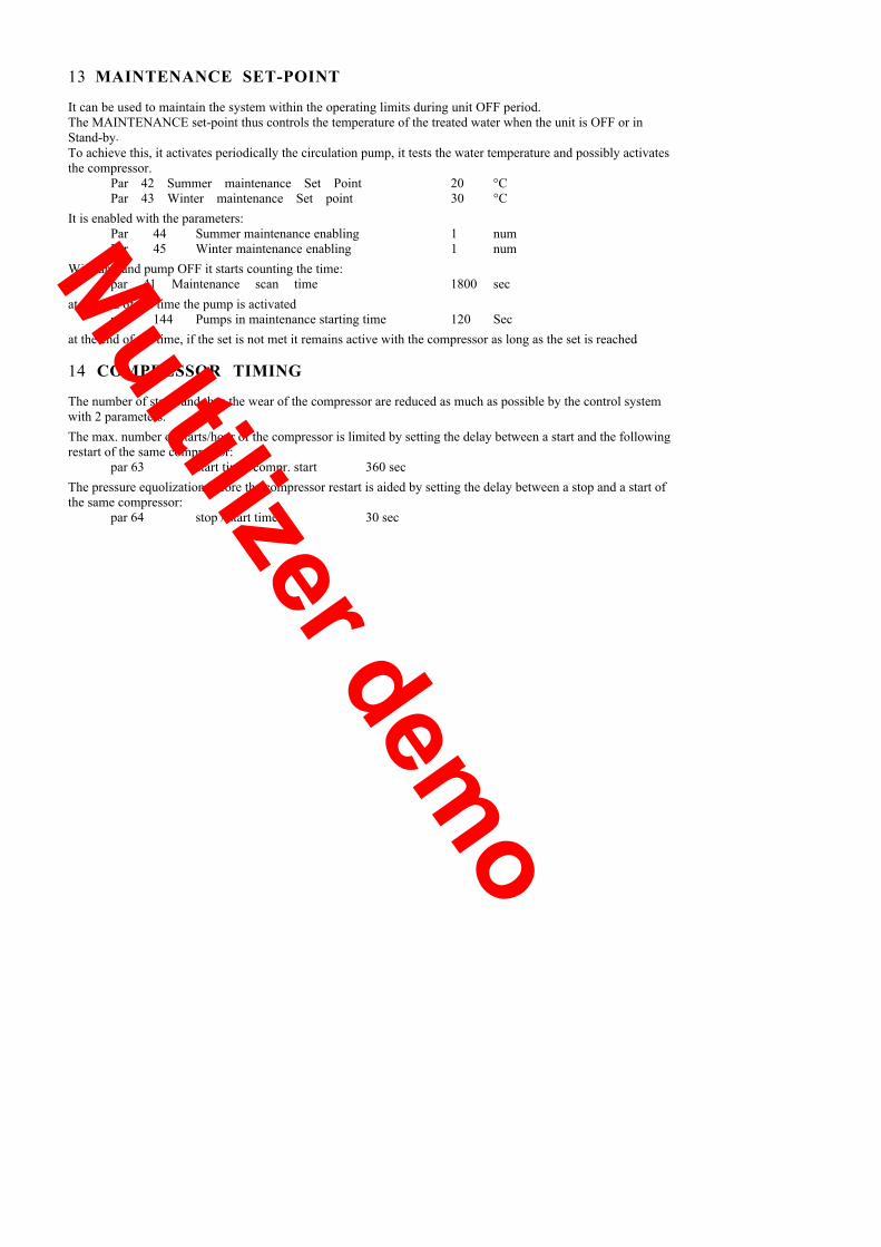
13 MAINTENANCE SET-POINT
It can be used to maintain the system within the operating limits during unit OFF period.The MAINTENANCE set-point thus controls the temperature of the treated water when the unit is OFF or inStand-by.To achieve this, it activates periodically the circulation pump, it tests the water temperature and possibly activatesthe compressor.
Par 42 Summer maintenance Set Point 20 °CPar 43 Winter maintenance Set point 30 °C
It is enabled with the parameters:Par 44 Summer maintenance enabling 1 numPar 45 Winter maintenance enabling 1 num
With unit and pump OFF it starts counting the time:par 41 Maintenance scan time 1800 sec
at the end of the time the pump is activatedpar 144 Pumps in maintenance starting time 120 Sec
at the end of the time, if the set is not met it remains active with the compressor as long as the set is reached.
14 COMPRESSOR TIMING
The number of starts and thus the wear of the compressor are reduced as much as possible by the control systemwith 2 parameters.The max. number of starts/hour of the compressor is limited by setting the delay between a start and the followingrestart of the same compressor:
par 63 start time/ compr. start 360 secThe pressure equolization before the compressor restart is aided by setting the delay between a stop and a start ofthe same compressor:
par 64 stop / start time 30 sec
Multilizer demo
temp. °C
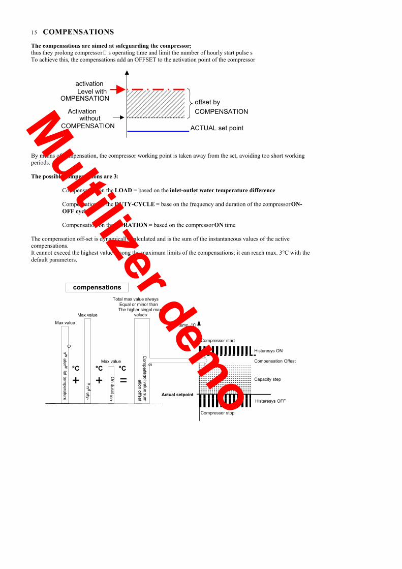
15 COMPENSATIONS
The compensations are aimed at safeguarding the compressor;thus they prolong compressor�s operating time and limit the number of hourly start pulse sTo achieve this, the compensations add an OFFSET to the activation point of the compressor
offset byCOMPENSATION
ACTUAL set point
activationLevel with
OMPENSATION
Activation levelwithout
COMPENSATION
By means of compensation, the compressor working point is taken away from the set, avoiding too short workingperiods.
The possible compensations are 3:
Compensation on the LOAD = based on the inlet-outlet water temperature difference
Compensation on the DUTY-CYCLE = base on the frequency and duration of the compressor ON-OFF cycles
Compensation on the DURATION = based on the compressor ON time
The compensation off-set is dynamically calculated and is the sum of the instantaneous values of the activecompensations.It cannot exceed the highest value among the maximum limits of the compensations; it can reach max. 3°C with thedefault parameters.
Capacity step
Compensation Offest
Histeresys ON
Actual setpointHisteresys OFF
Compressor stop
Compressor start
compensationsO
n duration
on d
uty-
On w
ater inlet tem
perature
Com
pensation offset
Singolvalue
sum
+ + =°C °C °C
Max value
Total max value alwaysEqual or minor thanThe higher singol max.
values
Max value
Max value
Multilizer demo
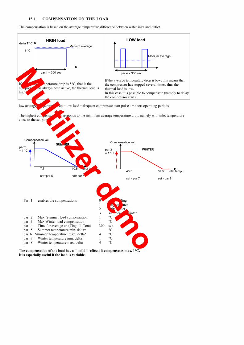
15.1 COMPENSATION ON THE LOAD
The compensation is based on the average temperature difference between water inlet and outlet.
If the average temperature drop is 5°C, that is thecompressor has always been active, the thermal load ishigh.
If the average temperature drop is low, this means thatthe compressor has stopped several times, thus thethermal load is low.In this case it is possible to compensate (namely to delaythe compressor start).
LOW load
Medium average
par 4 = 300 sec
HIGH loaddelta T °C
Medium average5 °C
par 4 = 300 sec
low average temperature drop = low load = frequent compressor start pulse s + short operating periods
The highest compensation corresponds to the minimum average temperature drop, namely with inlet temperatureclose to the set-point.
Compensation val.SUMMER
par 2= 1 °C
7,5 10,5 Inlet temp..
set+par 5 set+par 6
Compensation val.
par 3 WINTER= 1 °C
40.5 37.5 Inlet temp..
set - par 7 set - par 8
Par 1 enables the compensations 0 not enabling1 only summer2 only winter3 summer and winter
par 2 Max. Summer load compensation 1 °Cpar 3 Max.Winter load compensation 1 °Cpar 4 Time for average on (Ting. � Tout) 300 secpar 5 Summer temperature min. delta* 1 °Cpar 6 Summer temperature max. delta* 4 °Cpar 7 Winter temperature min. delta 1 °Cpar 8 Winter temperature max. delta 4 °C
The compensation of the load has a �mild� effect: it compensates max. 1°C.It is especially useful if the load is variable.
Multilizer demo

15.2 COMPENSATION ON DUTY-CYCLE
The compensation on DUTY-CYCLE is based on the ratio : operating time
Oper. time + stop time
This function is based on elaborate mathematical calculations and test checks.The resulting values are thus to be meant as standard and cannot be modified.Please note that the worst conditions occur for duty-cycle values included in the range between 20% and 50% (ONtime = 50 % OFF time) .
53 Enables compensation on duty 1 num54 Value of critic duty 20 %55 Max. value compensation on duty 1,5 °C56 Time of medium duty calculation 1800 sec
The compensation on the duty operates a standard optimisation of the ON-OFF cycles; thus, it is of generaluse and must be enabled always.
15.3 COMPENSATION ON THE DURATION
The compensation on the DURATION is based on the compressor ON time. Short ON times, even if followed bylong OFF periods, are critical for the compressor (lubrication problems).
That's why at the end of each operating cycle of the compressor the controller checks the duration (compressorON).If the ON time is lower than 200 sec the controller increases the compensation, then it checks if ON reaches 200sec; otherwise, it increases the compensation again. The compensation is increased max. three times the max.value.If the ON time is longer than 300 sec, the compensation is decreased with the same logic.
Par 57 It enables the duration of compensation 1 numPar 58 Min. operating time 200 secPar 59 Max. operating time 300 secPar 60 Max. duration comp. value 1 °C
The duration compensation has an �incisive� effect: it compensates up to 3°C.It is useful when the water content is limited.The incisiveness is detrimental to the low temperature control accuracy: in industrial applications, where a finetemperature control is required, this compensation can be disabled but a fair water quantity in the system isnecessary.PLEASE NOTE THAT WITH SHORT COMPRESSOR ON PERIODS IT IS POSSIBLE TO HAVE ALOW AVERAGE TEMPERATURE DROP; IN THIS CASE, THE LOAD COMPENSATION WOULDHAVE A LIMITED EFFECT.
ON compr. with active compensationON
Averagetemp. drop
Multilizer demo

16 TEMPERATURE CONTROL
The temperature control is based on the outlet temperature and is based on temperature drop between water inletand outlet defined while designing the system
Par 37 Summer temperature average 5 °CIf the temperature drop on the system is not 5°C, it is basic to update the parameter value to the current temperaturedrop on the system; otherwise, the adjustment logic is distorted.The cooling/heating capacity supplied by the individual resources is defined (capacity step):
single capacity stepthe compressor alone supplies 100% of the required power (SUMMER)
double capacity stepthe compressor alone supplies only a part of the required power (WINTER with electric heaters)
Par 72 Compressor output capacity 70 %Par 177 Output by the integration heaters 30 %
The controller can activate one and only one step at a time, and only after the activation scanning time (status 4 ,page 20) .The activation scan time is not fixed, rather it changes according to the difference between water outlettemperature and current set-point value. The higher the difference value (both positive and negative) the shorter theinterval between scanning points.
Par 34 Max. activation scanning time 1200 secPar 35 Min. activation scanning time 120 sec
The release of active power steps can take place one step at a time, except the safety devices, when the releasescanning time has elapsed.
Par 36 Release scan time 10 sec
16.1COOLING
compressor ON if :at the end of the scanning time the outlet water temperature is over the current set-point (which considersthe possible corrections) plus the capacity step that the compressor can supply
Drop
Offest compensations
ON Hysteresis
temp. °C
supplied by the compressor
Actual setpoint
OFF Hysteresis
ompressor offC
Compressor on
Scan time
START ZONECOMPRESSOR
SENSING
SENSING
SENSING
SENSING
KEY
ON hysteresispar 40 First step activation hysteresis
OFF hysteresispar 39 Last step release hysteresis
Compensation offsetsee pag 339
Capacity step supplied by the compressorpar 37 summer temperature delta ( 5 °C ).
compressor OFF when the temperature goes below the set-point minus hysteresis last step
Par 37 Summer temperature delta 5 °Cpar 39 Last step release hysteresis -0.3 °Cpar 40 First step activation hysteresis -0.3 °Cpar 72 Compressor 1 capacity 100 %
Output capacity c1 always expressed as percentage of deltatc and in this case equal to 100% (single-compressorunit in cooling), namely the design 5°c
Multilizer demo

temp. °C
Actual setpoint
16.2HEATING
In this mode also the heaters can be installed and managed, that is a second capacity step integrating the first one.Thus, the total capacity is distributed between compressor and electric heaters.Compressor ON if :
at the end of the scanning time the outlet water temperature is below the current set-point (which considersthe possible corrections) plus the capacity supplied by the single capacity step of the compressor.
Heaters ON if :the scan time has started and ended, if the outlet temperature is over the heater capacity step.
If the heaters are not installed, the capacity step supplied by the compressor is equal to the total capacity step as inthe cooling mode.
Par 37 Summer temperature delta 5 °Cpar 38 Winter temperature delta 5 °Cpar 39 Last step release hysteresis 0.3 °Cpar 40 First step activation hysteresis 0.3 °Cpar 72 Compressor output power 70 * %par 161 Cycle reversing valve polarity 0 numpar 177 Output by the integration heaters 30 * %
* the value is indicative: it depends on how the power is distributed between heaters and compressor.
drop
Compensation offset
ON Hysteresis
OFF Hysteresis
Compressor switching-OFF
Compressor switching on
OFFOFF
STARTCOMP
Scan time
+ Time
COMPRESSORE.g. 70% di DeltaTH
HEATERSE.g.. 30% di DeltaTH
100% of capcity step
DeltaTH
Integration heaterStart are (after compressor
Start,only)
Compressor capcity stepHeater capcity step
OFF ON
ON
OFF
Heater switching-off
KEY
• ON Hysteresis : par 40 First step activation hysteresis• OFF Hysteresis : par 39 Last step release hysteresis, heater switching-off area, too• Compensation offset : see page 33• Compressor capacity step: calculated as percentage of par 38 (Winter temperature delta, the total capacity
step the machine can supply in heating).Heater drop: calculated as percentage of par 38 (Winter temperature delta)
Multilizer demo

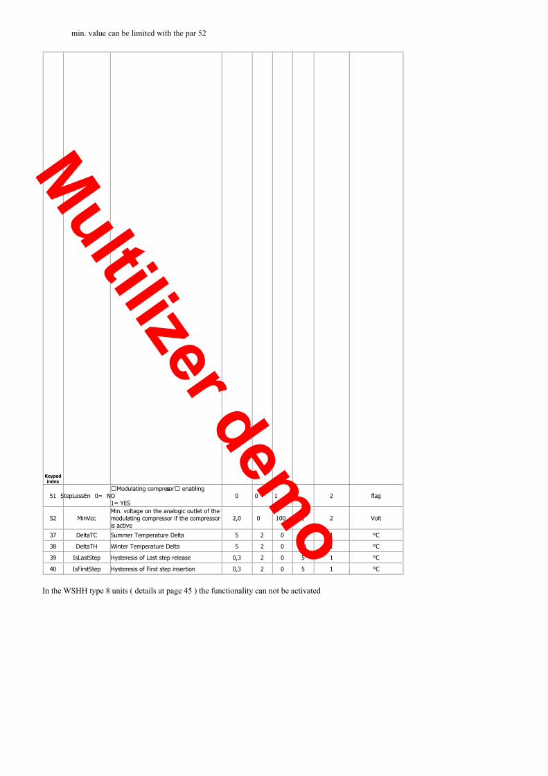
17 DIGITAL SCROLL MODULATING COMPRESSOR
The function , if enabled with par 51 = 1, allows to control a modulating compressor .Characteristics of the pilot signal :• is a function of the INLET water temperature• is a 0-10Vcc• the min. value can be limited with the par 52
Multilizer demo

NG COMPRESSOR
NG
CO
The function , if enabled with par 51 = 1, allows to control a modulating compressor .Characteristics of the pilot signal :• is a function of the INLET water temperature• is a 0-10Vcc• the min. value can be limited with the par 52
MPRESSOR
Thefunction ,ifenabledwithpar51 =1,allows tocontrol amodulatingcompressor .Characteristicsof thepilotsignal :•
Multilizer demo

unction of the INLET water temperature• is a 0-10Vcc
•
• the min. value can be limited with the par 52
•
Multilizer demo
min. value can be limited with the par 52
Keypadindex
51 StepLessEn 0= NO�Modulating compressor� enabling
1= YES0 0 1 0 2 flag
52 MinVccMin. voltage on the analogic outlet of themodulating compressor if the compressoris active
2,0 0 100 1 2 Volt
37 DeltaTC Summer Temperature Delta 5 2 0 20 1 °C
38 DeltaTH Winter Temperature Delta 5 2 0 20 1 °C
39 IsLastStep Hysteresis of Last step release 0,3 2 0 5 1 °C
40 IsFirstStep Hysteresis of First step insertion 0,3 2 0 5 1 °C
In the WSHH type 8 units ( details at page 45 ) the functionality can not be activated
Multilizer demo

COOLING HEATING
ANALOGIC
INLET temp.
DIGITAL
OUTLET temp.
T ing
P 40P 39
SetCool
0 Vcc
MinVcc
100%Vcc
P 37
T out
P 40P 39
SetCool
OFF
ON
P 37
T ing
P 40 P 39
SetHeat
0 Vcc
MinVcc
100%Vcc
P 38
T out
P 40 P 39
OFF
ON
P 38
SetHeat
Multilizer demo

18 ELECTRIC HEATER CONTROL
While heating, besides the compressor, optionally, it is possible to use the electric heaters.The operating modes and thus the adjustment logics can be different, as indicated here below.
If present, is possible to perform the temperature control in heatwith the Tout1 probe , installed on the electric heater output .The temperature control in cool will be performed always by theTout probe installed downstream from the exchanger.
70 it enables the heater output probe 1 YES , 0 NO150 offset temp. uscita riscaldatore elettrico °C
If the Tout1 is present, the antifreeze alarm is monitored fromboth the probes :• the Tout activates the antifreeze heaters on the exchanger• the Tout1 activates the integration heaters
T Ext
T IN
T OUT1T OUT
UNIT WITHOUT HEATERSThe unit can heat only by means of the compressor
Par 178 Compressor oper. enabling in heating 0 numPar 179 Power limit enabling for ext. temperature 0 num
18.1HEATERS AS INTEGRATION ELEMENTThe heaters integrate the compressor work.If it is defrosting or is stopped due to alarms, it becomes the main heating component.Starting from the machine ON, the heaters before operating wait for a delay time controlled by parameters; thesame occurs also during the maintenance step (see page 32) at each pump restart.
72 Compressor capacity 70 * %177 Capacity by the integration heaters 30 * %178 Compressor operation enabling in heating 1 num179 Power limit enabling for ext. temperature 0 num182 Heater timeout 1200 sec
* the value is indicative: it depends on how the power is distributed between heaters and compressor
18.2ELECTRIC HEATERS REPLACING THE COMPRESSORIn this mode the electric heaters operate only as an alternative to the compressor:• when this is excluded due to the external temperature limit• when this is excluded due to an alarm.
With external temperatures lower than parameter 180 the only available step is represented by the heaters.The compressor is enabled again when the heat pump operates for external temperatures over par 180 + 2°C.
177 Capacity by the integration heaters 100 %178 Compressor oper. enabling in heating 1 num179 Power limit enabling for ext. temperature 1 num180 Ext. temp. limit at the compressor oper. 0 °C
18.3MAIN ADJUSTMENT COMPONENT IN HEATINGIn this case heaters are the only heating element of the unitThe compressor does not operate in heating mode ( par 178 = 2 ) .
178 Compressor oper. enabling in heating 2 num179 Power limit enabling for ext. temperature 1 num
Multilizer demo

18.4POWER LIMITING ON EXTERNAL TEMPERATURE
In this case the operation of compressor and heaters in heating mode is subject to the external temperatureconditions as shown in the diagram.
1° zonecompressor ENABLED, heaters DISABLED
2° zonecompressor ENABLED, heaters ENABLED
3° zonecompressor DISABLED, heaters ENABLED
178 Compressor oper. enabling in heating 2 num179 Power limit enabling for ext. temperature 2 num181 Differential on ext. temp. limit for heater act 5 °C
HEATERS CONTROL OUTPUTS
The heaters control mode described above is ON � OFF.Anyway, it is possible to control the heaters proportionally, using the plug-in module and a diving signal (optionstill to be implemented, not available at the present).
apacity
10 Vd
0 Vdc
°C
Set Point
c
Heater temperaturedrop
ON
OFF0 %
100 %
Digital
Analogue
4
1
230 V 50 Hz
FN
CN33
6
GND 0-10 VDC
BASIC MODULE PLUG-IN MODULE
Ext
erna
l tem
pera
ture
1a zone COMPRESSOR enabled
Dead zone = 2 °C0 °C par 180 = 0 °C
2a zone
COMPRESSOR + HEATERSpar 181 = 5 °C
Dead zone = 2 °C- 5 °C
3a zona HEATERS ENABLED
Multilizer demo

18.5ANALOGICAL OUTPUT LIMITATION
With the par 207 is possible to define the max. value of the integration heaters pilotage when they are used together with thecompressor .
Keypadpar Mnemonic Description Default Min Max Tenths pwd level U.M.
207 MaxInteg Max. value of the CN3_3/6 analogical output when theheaters are actives together with the compressor 100 0 100 0 1 %
The CN3 analogical output limitation on the PLUG-IN module, pin 3/6 , is active when the heaters are managed :
Par 178ModeHeater
Par 179LimPotTextEn
Electric elements only as integration element 1 0
Electric elements in the place of the compressor 1 1
Power limitation on the external temperature 2 2
19 MANAGEABLE UNIT TYPES
type example 159 106 162 119
1 ventilation ON for compressor ON WSA 0 0 0 0
4 pressurised ventilation WSAT 2 0 0 0
5 pressurised ventilation, defrosting in temperature WSAN 2 0 1 0
6 condensation in water , pressurised modulating valve WSH 2 1 0 0
7 condensation in water, pressurised modulating valve,reversing cycle on gas, management of pump to condenser WSHN 2 1 1 0
8 condensation in water, reversing cycle on water,management of pump to condenser WSHH 1 2 1 0
9 Only heat pump with defrosting at hot gas , withoutreversing cycle valve WBAN 2 0 1 2
10 Water condensing, valve On for compressor On, antifreezeprobe Not active WSH 0 1 0 0
11 Water condensing, valve On for compressor On, antifreezeprobe active WSH 1 1 0 0
12 Inversing cycle on gas, water condensing, valve On forcompressor On, antifreeze probe Not active WSHN 0 1 1 0
13 Inversing cycle on gas, water condensing, valve On forcompressor On, antifreeze probe active WSHN 1 1 1 0
14 WSH (water condensing, pressurised modulating valve,antifreeze probe Not active) WSH 3 1 0 0
15 WSHN (Inversing cycle on gas, water condensing,pressurised modulating valve, antifreeze probe Not active) WSHN 3 1 1 0
A. WSHH � UNIT OF TYPE 8The unit is reversible on the water circuit so are present the following variations :
EVAPORATOR output probe control in cooling and antifreezeCONDENSER output probe control in heating and antifreezeFan digital output pump control output to condenser
The pump to condenser :• It is activated in advance respect the compressor ( par 100 Tstartup )• It stops in late respect the compressor ( par 107 TimeOffV )
Multilizer demo

B. WBAN � UNIT OF TYPE 9
The unit can operate exclusively for hot water production .The reversing cycle valve does not exist ; the defrosting is performed with a defrosting valve with hot gas .The expansion plug-in module is necessary .
It is possible to manage a 3-way valve for the production of sanitary hot water with a dedicated set point ( par 117 )With the par 50 = 1 the 2° set point input on the main board is set as SANITARY WATER REQUEST.
MODE HEAT/COOLinput 2° setpoint input VALVE SET POINT 2° SET POINT
HEATING OFF ON to theinstallation set HEAT 2° setpoint HEAT
*
HEATING+ H2O SANITARIA OFF OFF to the boiler SetH2OSanitaria not manageable
COOLING ON ON to the boiler Temperature control NOT ALLOWED
COOLING+ H2O SANITARIA ON OFF to the boiler SetH2OSanitaria not manageable
* enable :• from led keypad• setting par 49 =1
par Description Meaning value49 Comando2°Set 2° set point mode control from parameter 0
50 EnH2OSanitaria Enabling of the sanitary water valve management 0
117 SetH2OSanitaria Sanitary water Set Point 35
140 PlugInEn It enables the PLUG-IN presence. 1=YES / 0=NO
External exchanger
Internal exchanger
Compressor
Gas defrosting valve
Te
YVR
BOILER
rmostatica
Electric heater
Water valve
Multilizer demo
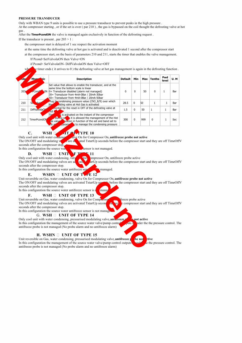
PRESSURE TRANSDUCEROnly with WBAN type 9 units is possible to use a pressure transducer to prevent peaks in the high pressure .At the compressor starting , or if the set is over ( par 210 ) , the gas is bypassed on the coil thought the defrosting valve at hotgas .After the TimerPcondON the valve is managed again exclusively in function of the defrosting request .If the transducer is present , par 203 > 1 :• the compressor start is delayed of 1 sec respect the activation moment• at the same time the defrosting valve at hot gas is activated and is deactivated 1 second after the compressor start• at the compressor start, on the basis of parameters 210 and 211, starts the timer that enables the valve management.
If Pcond>SetValvolaON then Valve=ONif Pcond< SetValvolaON- DiffValvolaON then Valve=OFF
• when the timer ends ( it arrives to 0 ) the defrosting valve at hot gas management is again in the defrosting function .
Index Mnemonic Description Default Min Max Tenths Pwdlevel U. M
203 EnPCondPlugIN
Set value that allows to enable the transducer, and at thesame time the bottom scale is linear0= Transducer disabled (alarm not managed)30= Transducer from 4mA-0Bar / 20mA-30bar50= Transducer from 4mA-0Bar / 20mA-50bar
0 0 50 0 1 Bar
210 SetValvolaON Plug In condensing pressure value (CN3_8/9) over whichthe defrosting valve at Hot Gas is activated 28.5 0 50 1 1 Bar
211 DiffValvolaON Differential for the reset in OFF of the defrosting valve atHot Gas 1.5 0 50 1 1 Bar
212 TimerPcondON
Timer that is activated on the instant of the compressorstart during which it is allowed the management of the HotGas valve activation in function of the set and band set tothe added parameters to manage the condensing pressure
300 0 999 0 1 Sec
C. WSH � UNIT OF TYPE 10Only cool unit with water condensing, valve On for Compressor On, antifreeze probe not activeThe ON/OFF and modulating valves are activated TstartUp seconds before the compressor start and they are off TimeOffVseconds after the compressor stop.In this configuration the source water antifreeze sensor is not managed.
D. WSH � UNIT OF TYPE 11Only cool unit with water condensing, valve On for Compressor On, antifreeze probe activeThe ON/OFF and modulating valves are activated TstartUp seconds before the compressor start and they are off TimeOffVseconds after the compressor stop.In this configuration the source water antifreeze sensor is not managed.
E. WSHN � UNIT OF TYPE 12Unit reversible on Gas, water condensing, valve On for Compressor On, antifreeze probe not activeThe ON/OFF and modulating valves are activated TstartUp seconds before the compressor start and they are off TimeOffVseconds after the compressor stop.In this configuration the source water antifreeze sensor is not managed.
F. WSH � UNIT OF TYPE 13Unit reversible on Gas, water condensing, valve On for Compressor On, antifreeze probe activeThe ON/OFF and modulating valves are activated TstartUp seconds before the compressor start and they are off TimeOffVseconds after the compressor stop.In this configuration the source water antifreeze sensor is not managed.
G. WSH � UNIT OF TYPE 14Only cool unit with water condensing, pressurised modulating valve, antifreeze probe not activeIn this configuration the management of the source water valve/pump control outputs is under the the pressure control. Theantifreeze probe is not managed (No probe alarm and no antifreeze alarm)
H. WSHN � UNIT OF TYPE 15Unit reversible on Gas, water condensing, pressurised modulating valve, antifreeze probe not activeIn this configuration the management of the source water valve/pump control outputs is under the the pressure control. Theantifreeze probe is not managed (No probe alarm and no antifreeze alarm)
Multilizer demo

20 CIRCULATION PUMP
It is possible to control:• single pump on the unit• single pump + stand-by pump• modulating pump controlling the assisted starts of the compressor
(changing the number of pump revolutions the water flow rate is modulated in order to, keepthe water temperature within the working limits at the start)
Par 141 = 0 single pump on the unit1 single pump + stand-by pump2 one pump with variable flow
The different outputs to control the pumps are all on the main control module.
12
11
10
98
765432
1
212019181716151413
+5VTxRx
DTGRN
D
COMMON
FIRST SPEEDPUMP
COMMON
FIRST PUMP OR SINGLEPUMP SPEED
REFERENCE PWM 0-10 V
By precise choice control is carried out on the system water pressure: the relevant input on the card is bridged (CN1 pin 9 e 11 )
Par 142 Flow by-pass from pump start 25 secPar 143 Delay at Comp. start from pump activation 25 secPar 144 Maintenance pump start time 120 SecPar 145 Delay at pump switch-off from comp. OFF 120 Sec
20.1SINGLE PUMP
The circulation pump sets ON every time the unit is switched on.(actually, first a check on the system charged with water through the input 9 of CN1 is made; being this bridged, itis always positive).
On page 22 the flow alarm management is described.
20.2SINGLE PUMP + STAND-BY PUMP
There are 2 pumps:• one operating• one in stand-by ready to start if the first one does not work roperly
The stand-by pump is always the one having less running hours.
THE ONLY DIFFERENCE WITH RESPECT TO THE PREVIOUS CYCLE IS A TRIAL IS MADE WITHTHE STAND-BY PUMP BEFORE STOPPING THE UNIT BY FLOW ALARM ( SEE PAGE 25 ) .
Multilizer demo
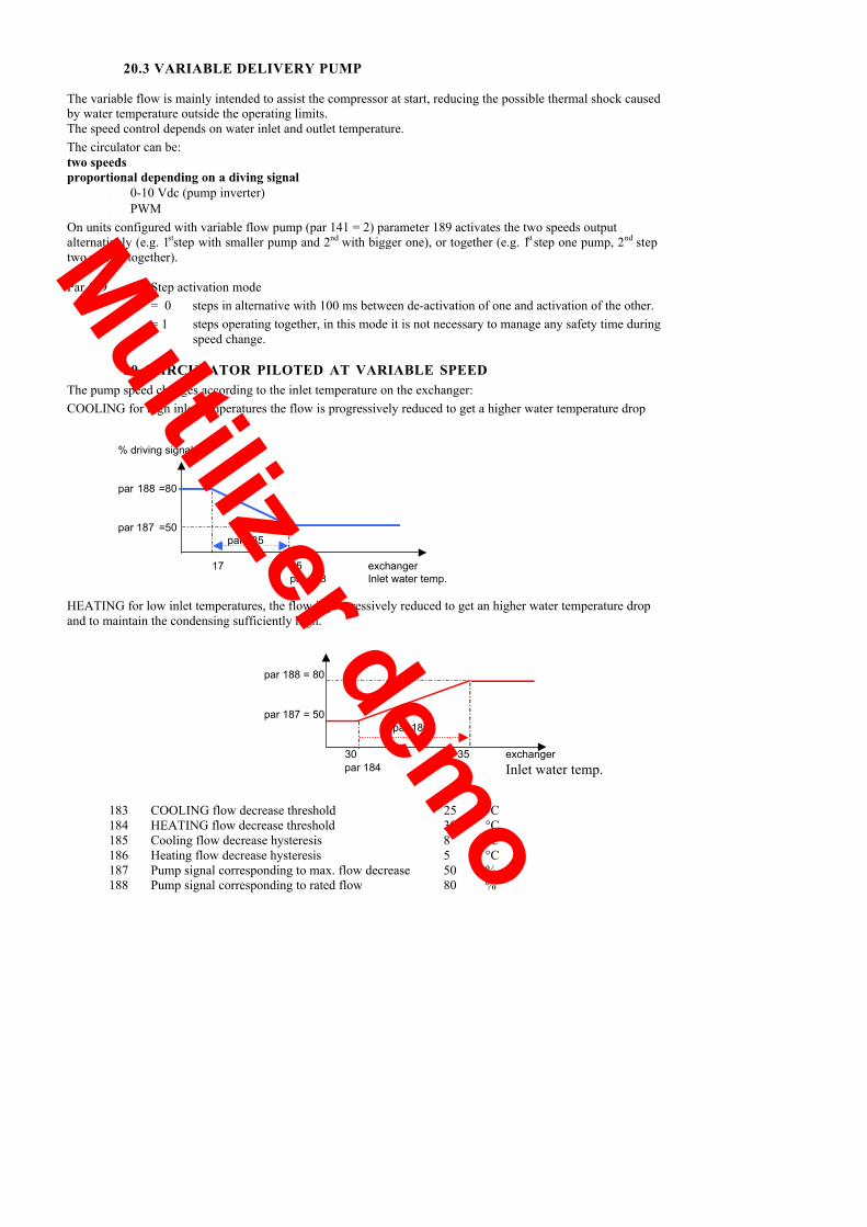
% driving signal
par 188 =80
par
20.3 VARIABLE DELIVERY PUMP
The variable flow is mainly intended to assist the compressor at start, reducing the possible thermal shock causedby water temperature outside the operating limits.The speed control depends on water inlet and outlet temperature.The circulator can be:two speedsproportional depending on a diving signal
• 0-10 Vdc (pump inverter)• PWM
On units configured with variable flow pump (par 141 = 2) parameter 189 activates the two speeds outputalternatively (e.g. 1 step with smaller pump and 2st nd with bigger one), or together (e.g. 1 step one pump, 2st nd steptwo pumps together).
Par 189 Step activation mode= 0 steps in alternative with 100 ms between de-activation of one and activation of the other.= 1 steps operating together, in this mode it is not necessary to manage any safety time during
speed change.
20.4CIRCULATOR PILOTED AT VARIABLE SPEEDThe pump speed changes according to the inlet temperature on the exchanger:COOLING for high inlet temperatures the flow is progressively reduced to get a higher water temperature drop
187 =50par 185
17 25 exchangerpar 183 Inlet water temp.
HEATING for low inlet temperatures, the flow is progressively reduced to get an higher water temperature dropand to maintain the condensing sufficiently high.
par 188 = 80
par 187 = 50par 186
30 35 exchangerpar 184 Inlet water temp.
183 COOLING flow decrease threshold 25 °C184 HEATING flow decrease threshold 30 °C185 Cooling flow decrease hysteresis 8 °C186 Heating flow decrease hysteresis 5 °C187 Pump signal corresponding to max. flow decrease 50 %188 Pump signal corresponding to rated flow 80 %
Multilizer demo

2n
20.5TWO SPEED CIRCULATOR
The pump can operate only at a reduced speed or at its nominal speed according to the inlet water temperature.
COOLING
The concept is similar to the previously described one :for high inlet temperature the speed is reduced to get a higher water heat drop
2nd
peeds
1st
peedpar 185 = 8
°C
17 par 183 water IN= 25
s
HEATING
For high inlet temperatures the speed is increased to get a lower water heat drop
FORCINGS• MAX. SPEED: in case of anti-frost pre-alarm• MIN. speed: in case of high pressure pre-alarm• MAX. SPEED: in cooling if the inlet temperature is over 25°C (par 183 COOLING delivery decrease
threshold) and the outlet temperature is within the off hysteresis (par 39 = 1°C, see diagram on page 32 )• MAX. SPEED: in heating if the inlet temperature is below 30°C (par 184 HEATING delivery
decrease threshold) and the outlet temperature is within the off hysteresis (par 39 = 1°C, seediagram on page 37 )
d
speed
1st
peedpar 186 = 5
°C
par 184 35 water IN= 30
s
Multilizer demo

21 CONDENSING CONTROLthe controller can manage units:• Air cooled, using fans• Water cooled, using valves
in both cases the regulation can be• On-Off type• Proportional according to condensing pressure• proportional according to condensing temperature
The configuration is carried out by the parameters below:106 Condensation type159 Selection of the type of condensation probe162 Configuration of the unit as CHILLER or HEAT PUMP
PARAMETERS
Unit type 159 162 106
WSAT (Ventilation On for Compressor On) 0 0 0
WSAN (Ventilation On for Compressor On) 0 1 0
WSAT (Ventilation temperature controlled) 1 0 0
WSAT (Ventilation pressure controlled) 2 0 0
WSAN (Ventilation pressure controlled, defrosting temperature controlled) 2 1 0
WSH (Water cooled, valve modulating according to pressure) 2 0 1
WSHN (Cycle reversal on refrigerant side, valve modulating according topressure) 2 1 1
WSHH (Cycle reversal, pump management at the condenser) 1 1 2
21.1AIR COOLED UNITSThe condensation/evaporation fans are active only when the compressor is active.Their type can be:• ON-OFF• variable speed• with control according to condensing temperature• with control according to condensing/evaporating pressure
The parameters determining fan operating mode are:
92 Summer FAN start pressure with comp. off 23 Bar/°C93 Winter FAN start pressure with comp. off 0 Bar/°C94 Max. Fan speed pressure 3.7 bar/°C95 Min. Fan speed pressure 4.2 bar/°C96 Max. Fan cool pressure 17 bar/°C97 Min. Fan cool pressure 13,5 bar/°C98 Fan Cut-OFF Heat 4.8 bar/°C99 Fan Cut-OFF Cool 12 bar/°C100 Fan start pulse duration 5 sec101 Bypass cut-off duration 25 sec102 Max % Fan 100 %103 % Fan 40 %104 Fan % at start 70 %112 Summer HP pre-alarm set ( see page 25 ) 25 bar
Multilizer demo

ON-OFF TYPE REGULATION
COOLINGAt the compressor start:
regardless of the pressure value the fan activates for:par 100 fan start pulse duration 5 sec.
After the counting, the fan is kept in On if the pressure is higher thanPar 99 cool fan cut off 12 bar/°C
otherwise it remains active until:par 101 cut-off bypass duration 25 sec has elapsed
During the compressor operation:the fan, when stopped, starts again when
Par 97 min fan speed pressure cool 13,5 bar/°C is exceededand stops when the pressure drops below
par 99 cool fan cut-off 12 bar / °CHEATINGAt the compressor start:
regardless of the pressure value the fan activates for:par 100 fan start pulse duration 5 sec.
After that fan is kept ON if the pressure is lower thanPar 98 heat fan cut off 4,8 bar / °C
otherwise it remains active untilpar 101 cut-off bypass duration 25 sec has elapsed
During the compressor operation:the fan, when stopped, starts if pressure drops below
par 95 Min fan speed pressure heat 4,2 bar/°Cand stops when the pressure goes over
par 98 cut-off heat fan 4,8 bar / °C
REGULATION ACCORDING TO CONDENSING TEMPERATURE WITH PROPORTIONAL PHASECUT OR INVERTER OUTPUT (COOLING ONLY)COOLING MODE it is possible to control the fan speed according to condensing temperature.
CONDENSINGTEMPERATURE
40 % =par 103 =
IN SPPEDM
100 % =par 102 =MAX speed
70 % = par104 = %
ATPICK-UP
5 sec = durationStart pulse = par 100
25 sec = par101
fanspeed
26 °C =par 99 =
CUTOFFCOOL
30 °C =par 97 =
MIN temp.COOL SPEED
42 °C =par 96 =. MAX temp.COOL SPPED
Multilizer demo

REGULATION ACCORDING TO CONDENSING PRESSURE WITH PROPORTIONAL PHASE CUTOR INVERTER OUTPUT
COOLING
CONDENSIN
PRESSURE.
40 % =103 =
IN SPEED
80 % =par 102
=MAXSPEED
70 % =par 104 =% AT
START PULSE
parM
5 sec = durationStart pulse = par 100
100 % =Max Fan
Silent
25 sec =par 101
12 bar =par 99 =
CUTOFFCOOL
13.5 bar =par 97 =
Min.pressCOOL speed
17 bar =par 96 =
Max. press.COOL speed
FanSpeed
2 bar =par 113 =
deltapreal. HP
25 bar =par 112 =preALHP
MaxFanSilent is not defined by a parameter: it is always 100% of the speed.If par 102 = MaxFan = 100% that is Max. SPEED = MaxFanSilent, the �superventilation� does not take place.
HEATING
Evaporatingpressure
5 sec =par 100 =Start pulse duration
25 sec =par 101
FanSpeed
4.8 bar =par 98 =
CUT OFFHEAT
4.2 bar =par 95 =pres MIN
HEAT
3.7 bar =par 94 =
pres MAXHEAT
40 % =r 103 =papeedMIN s
70 % =r 104 =pase fanStart pul
100 % =par 102 =
MAX speed
21.2PRESSURE TRANSDUCER READING
It is possible to use a transducer with 0-30 bar or 0-50 bar field ( both correspond to the 4-20 ma output signal )par 67 bottom scale of the 4-20Ma pressure probe 30 = 30 bar , 50 = 50 bar
Multilizer demo

21.3 FAN FORCING WITH COMPRESSOR OFF
The function activates the condensing fans when , with compressors in off , the pressure/temperature on thecondensong coil reaches high values .The function is active only with unit in cooling .
ventilation Fan start Fan stop
ON �OFFExternal temp. Probe incontact with the coil to
enable with par 152par 158 - 2 ° C
Modulation in temperature Probe on the coil par 92 - 2 ° C
Modulation in pressure transducer par 92 - 2 barMultilizer demo
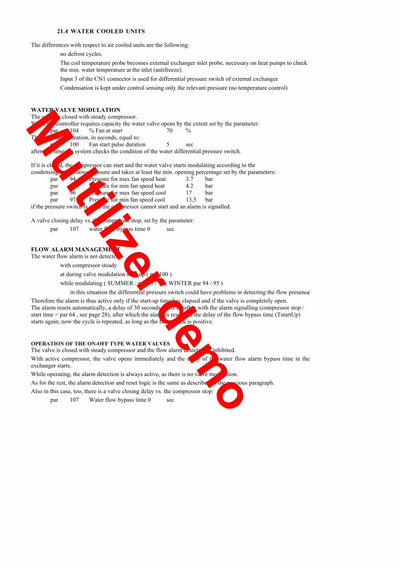
21.4 WATER COOLED UNITS
The differences with respect to air cooled units are the following:• no defrost cycles.• The coil temperature probe becomes external exchanger inlet probe, necessary on heat pumps to check
the min. water temperature at the inlet (antifreeze).• Input 3 of the CN1 connector is used for differential pressure switch of external exchanger.• Condensation is kept under control sensing only the relevant pressure (no temperature control)
WATER VALVE MODULATIONThe valve is closed with steady compressor.When the controller requires capacity the water valve opens by the extent set by the parameter:
par 104 % Fan at start 70 %This step has a duration, in seconds, equal to:
par 100 Fan start pulse duration 5 secafter this time the system checks the condition of the water differential pressure switch.
If it is closed, the compressor can start and the water valve starts modulating according to thecondensing/evaporating pressure and takes at least the min. opening percentage set by the parameters:
par 94 Pressure for max fan speed heat 3.7 barpar 95 Pressure for min fan speed heat 4.2 barpar 96 Pressure for max fan speed cool 17 barpar 97 Pressure for min fan speed cool 13,5 bar
if the pressure switch is open the compressor cannot start and an alarm is signalled.
A valve closing delay vs. the compressor stop, set by the parameter:par 107 water flow bypass time 0 sec
FLOW ALARM MANAGEMENTThe water flow alarm is not detected:
• with compressor steady• at during valve modulation start-up ( par 100 )• while modulating ( SUMMER : par 96 / 97 ; WINTER par 94 / 95 )• in this situation the differential pressure switch could have problems in detecting the flow presence.
Therefore the alarm is thus active only if the start-up time has elapsed and if the valve is completely open.The alarm resets automatically, a delay of 30 seconds starts together with the alarm signalling (compressor stop /start time = par 64 , see page 28), after which the alarm is reset and the delay of the flow bypass time (TstartUp)starts again; now the cycle is repeated, as long as the flow check is positive.
OPERATION OF THE ON-OFF TYPE WATER VALVESThe valve is closed with steady compressor and the flow alarm detection is inhibited.With active compressor, the valve opens immediately and the delay of the water flow alarm bypass time in theexchanger starts.While operating, the alarm detection is always active, as there is no valve modulation.As for the rest, the alarm detection and reset logic is the same as described in the previous paragraph.Also in this case, too, there is a valve closing delay vs. the compressor stop:
par 107 Water flow bypass time 0 sec
Multilizer demo
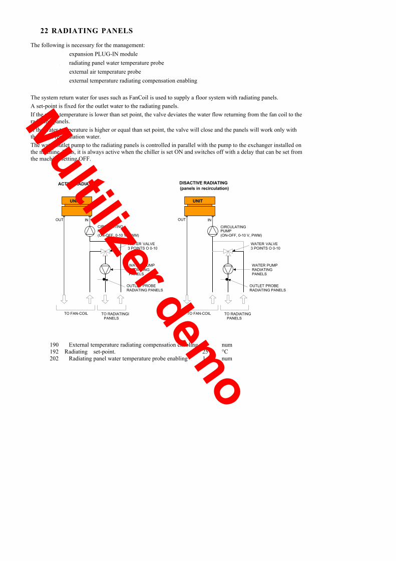
22 RADIATING PANELS
The following is necessary for the management:• expansion PLUG-IN module• radiating panel water temperature probe• external air temperature probe• external temperature radiating compensation enabling
The system return water for uses such as FanCoil is used to supply a floor system with radiating panels.A set-point is fixed for the outlet water to the radiating panels.If the water temperature is lower than set point, the valve deviates the water flow returning from the fan coil to theradiating panels.If the water temperature is higher or equal than set point, the valve will close and the panels will work only withtheir own recirculation water.The water outlet pump to the radiating panels is controlled in parallel with the pump to the exchanger installed onthe machine. Thus, it is always active when the chiller is set ON and switches off with a delay that can be set fromthe machine setting OFF.
OUT IN
TO FAN-COIL TO RADIATINGIPANELS
UNIT
CIRCULATINGPUMP(ON-OFF, 0-10 V, PWM)
WATER PUMPRADIATINGPANELS
OUTLET PROBERADIATING PANELS
WATER VALVE3 POINTS O 0-10V
IN
TO FAN-COIL TO RADIATINGPANELS
UNIT
CIRCULATINGPUMP(ON-OFF, 0-10 V, PWM)
WATER PUMPRADIATINGPANELS
OUTLET PROBERADIATING PANELS
WATER VALVE3 POINTS O 0-10V
ACTIVE RADIATING DISACTIVE RADIATING(panels in recirculation)
OUT
190 External temperature radiating compensation enabling. 1 num192 Radiating set-point. 25 °C202 Radiating panel water temperature probe enabling 1 num
Multilizer demo

22.1 VALVE CONTROL TO THE PANELS
As alternative, it is possible to control 3-point or proportional valves.There are 3 outputs for radiating panels:
• analogue 0-10 V• valve opening digital• valve closing digital
CALCULATION OF THE START THRESHOLD OF THE RADIANT VALVE CONTROLThe outlet temperature threshold for the control start is calculated with the parameter 169 TdeltaChiller :
Active control Inhibited control
COOL t mandata < SetPointRAD � 2 °C t mandata > SetPointRAD + 2 °C
HEAT t mandata > SetPointRAD + 2 °C t mandata < SetPointRAD � 2 °C
22.2 RADIANT SET-POINT
There are 3 modalities to set the radiant .
1. Value setting by parameter or by ModBus variable.The valve is managed to obtain water on the panels at the parameter value �192 SetPointTR� independentlyfrom the operating mode selected on the chiller.
2. Set point calculated in function of the external air temperature.The electronics determinates two reference set point ( summer / winter ) that are set automatially in base ofthe operating mode selected on the unit. This configuration is obtained setting �190 EnCompExttR = 1�
3. Summer set point correction in function of the dew temperature value.The system must be interfaced with a ModBus (Ex ElfoControl) net Master, able to communicate theambient UR and the ambient temperature values thorough the serial. In function of these information, analgorithm inside the board allows to correct the min. summer set point if the dew temperature valuecalculated is critical. This configuration is obtained setting �191 EnCompRugiada = 1�
2 - HEATINGWhile the external temperature increases, the heating demand decreases, and thus can be complied even with alower set-point (increasing the power efficiency).
27,028,029,030,031,032,033,034,035,036,0
setp
oint
4 5 6 7 8 9 1 0 1 1 1 2 1 3 1 4 1 5 1 6 1 7 1 8 1 9 2 0 2 1 2 2
external temp.
The set is automatically limited within the limits :par 198 Min heating set point 30 °Cpar 199 Max heating set point 35 °C
the actual value is function of the external temperature:par 200 Min external temperature heating 5 °Cpar 201 Max external temperature heating 20 °C
Multilizer demo
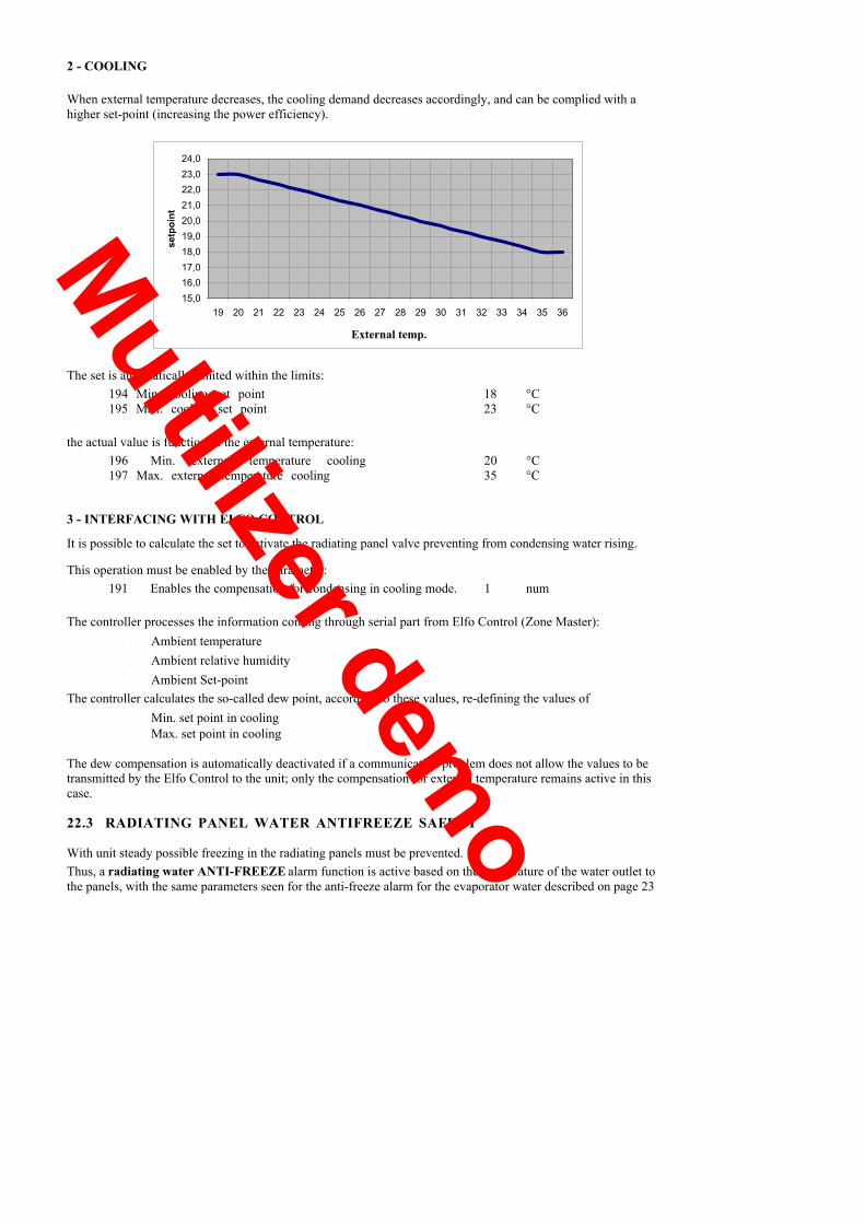
2 - COOLING
When external temperature decreases, the cooling demand decreases accordingly, and can be complied with ahigher set-point (increasing the power efficiency).
15,016,017,018,019,020,021,022,023,0
19 20 21 22 23 24 25 26 27 28 29 30 31 32 33 34 35 36
24,0se
tpoi
nt
temp. esternaExternal temp.
The set is automatically limited within the limits:194 Min. cooling set point 18 °C195 Max. cooling set point 23 °C
the actual value is function of the external temperature:196 Min. external temperature cooling 20 °C197 Max. external temperature cooling 35 °C
3 - INTERFACING WITH ELFO CONTROL
It is possible to calculate the set to activate the radiating panel valve preventing from condensing water rising.
This operation must be enabled by the parameter:191 Enables the compensation for condensing in cooling mode. 1 num
The controller processes the information coming through serial part from Elfo Control (Zone Master):• Ambient temperature• Ambient relative humidity• Ambient Set-point
The controller calculates the so-called dew point, according to these values, re-defining the values of• Min. set point in cooling• Max. set point in cooling
The dew compensation is automatically deactivated if a communication problem does not allow the values to betransmitted by the Elfo Control to the unit; only the compensation for external temperature remains active in thiscase.
22.3 RADIATING PANEL WATER ANTIFREEZE SAFETY
With unit steady possible freezing in the radiating panels must be prevented.Thus, a radiating water ANTI-FREEZE alarm function is active based on the temperature of the water outlet tothe panels, with the same parameters seen for the anti-freeze alarm for the evaporator water described on page 23
Multilizer demo
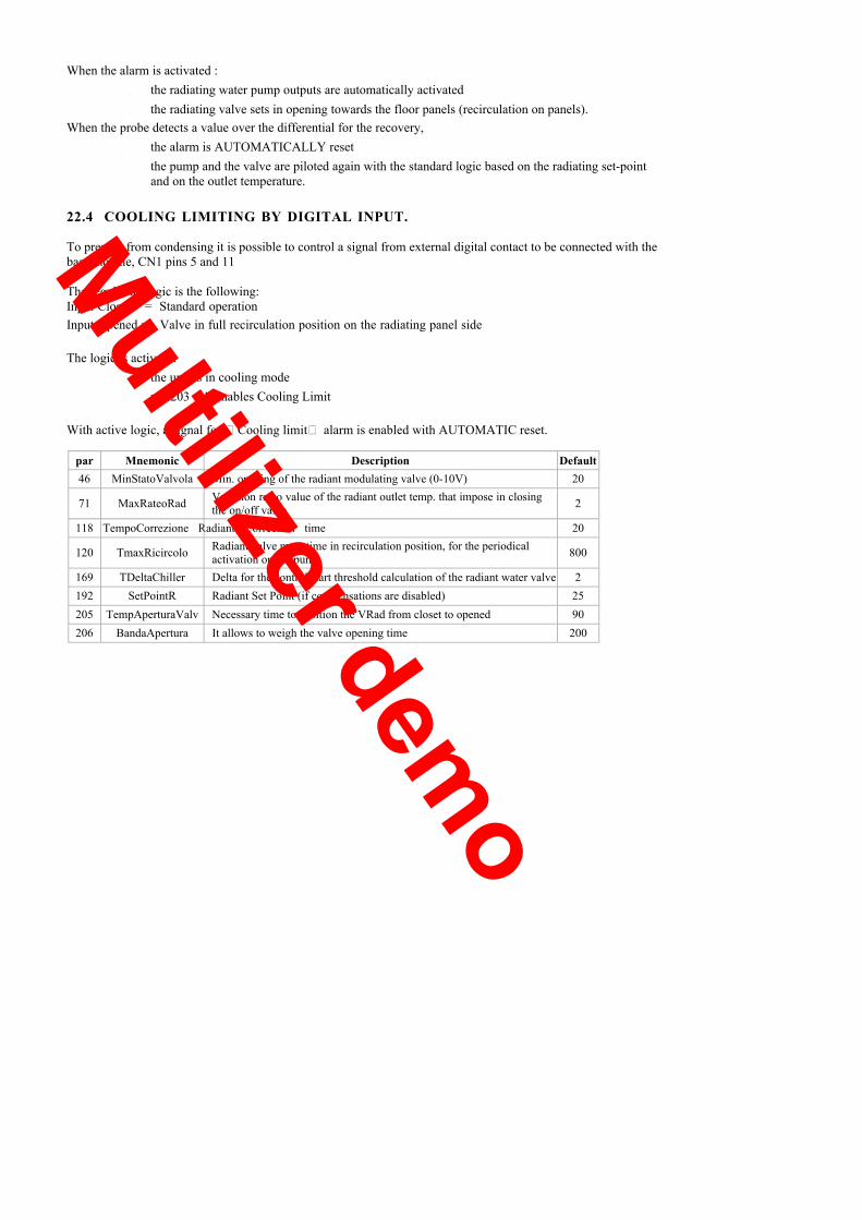
When the alarm is activated :• the radiating water pump outputs are automatically activated• the radiating valve sets in opening towards the floor panels (recirculation on panels).
When the probe detects a value over the differential for the recovery,• the alarm is AUTOMATICALLY reset• the pump and the valve are piloted again with the standard logic based on the radiating set-point
and on the outlet temperature.
22.4 COOLING LIMITING BY DIGITAL INPUT.
To prevent from condensing it is possible to control a signal from external digital contact to be connected with thebase module, CN1 pins 5 and 11
The regulation logic is the following:Input Closed = Standard operationInput Opened = Valve in full recirculation position on the radiating panel side
The logic is active if:• the unit is in cooling mode• par 203 = 1 Enables Cooling Limit
With active logic, a signal for �Cooling limit� alarm is enabled with AUTOMATIC reset.
par Mnemonic Description Default46 MinStatoValvola Min. opening of the radiant modulating valve (0-10V) 20
71 MaxRateoRad Variation rateo value of the radiant outlet temp. that impose in closingthe on/off valve 2
118 TempoCorrezione Radiant Correction time 20
120 TmaxRicircolo Radiant valve max. time in recirculation position, for the periodicalactivation on the pump 800
169 TDeltaChiller Delta for the control start threshold calculation of the radiant water valve 2192 SetPointR Radiant Set Point (if compensations are disabled) 25205 TempAperturaValv Necessary time to position the VRad from closet to opened 90206 BandaApertura It allows to weigh the valve opening time 200
Multilizer demo

BASIC TIME
2700 SECpar 132
180
23 DEFROSTING
Defrost can occur when:• the unit is working as heat pump• the compressor is active.
The cycle starts with:• a pressure test
� a defined threshold is exceeded• a counting is started
o at the counting end the temperature is checked� If it is lower than a defined value
• defrosting starts.
COUNTING CALCULATIONThe counting, or basic delay time for defrost, is dynamic and is calculated in two ways: according to externaltemperature or to the enthalpy.EXTERNAL TEMPERATURE ONLY
The basic delay time for defrost increases while the external temperature decreases.Indeed, it is supposed that when the external temperature decreases the humidity rate in air decreases, andtherefore the need for defrost is lower.
0 SECpar 131
- 10 °C 5 °C EXTERNAL TEMP.par 134 par 133
EXTERNAL TEMPERATURE + HUMIDITYor enthalpy defrostThe basic delay time is determined according to the air specific humidity calculated through the humidityprobe (optional, to be declared present with par 156).
The BASIC DELAY TIME for defrost changes depending on the variation of evaporating pressure (ratio).Practically, if the pressure:• decreases quickly the coil is icing and thus the counting must speed up• decreases slowly the counting can slow down• is stable (with low values, too) the counting keeps the values according to the graph above.
For example if the pressure in 1 minute falls down of 1 bar ( par130=1) , at every second the time is decreased of 4seconds ( par 129 ) .
Multilizer demo

Switch to defrost:• keeps the compressor active• the refrigerating circuit direction is reversed through the 4-way valve• The fans are stopped and the low pressure by-pass is active at reversal.• The safety devices remain active• Defrost is performed even if the controller does not require the step anymore.
Defrost end:• by temperature or max. time• the compressor is stopped• the compressor can restart in heating after having counted the dropping time or the compressor safety
times• the fans are activated at max. speed for 15 sec (par 136)
if the external temperature is over 3°C (par 137)
Setting the par 135 dropping time at 0, the compressor is not stopped at the of the defrosting but it remains active.
FORCING DEFROST FOR LOW PRESSUREIn special situations sudden drops in the evaporation pressure can occur (typically while counting the delay time fordefrosting, that is with low pressure/external temperature and with high humidity).The defrost forcing prevents such situations.It is active only if the counting of the delay time for defrost has been active for at least 10 minutes.Defrost starts immediately if the pressure drops below 1.4 bar (par 138 defrost forcing pressure), regardless of thetemperature value at the coil.
If this function is activated for more than 3 times, in the same circuit during one hour of machine operation, this issignalled in the alarm log.
DEFROSTING CONTROL PARAMETERS
121 Defrost Start Press. 3.4 bar122 Defrosting start temperature 1 °C123 Defrosting stop temperature 15 °C124 Max. defrost time 480 sec125 Max. defrost delay time 2700 sec126 Defrost transient duration 90 sec128 Defrost delta pressure 1,5 bar129 Max. counting IN defrost 4 num130 Max. pressure ratio 1 bar/min131 Min defrosting counting delay 1800 sec132 Max defrosting count. delay 2700 sec133 Ext. temperature min delay 5 °C134 Ext. temperature max delay -10 °C135 Drip time 60 sec136 Fan running time after defrost 15 sec137 Min external temperature fan activation after defrost 3 °C138 Defrost forcing pressure 1.4 bar156 External RH % probe enable 0 num
Multilizer demo
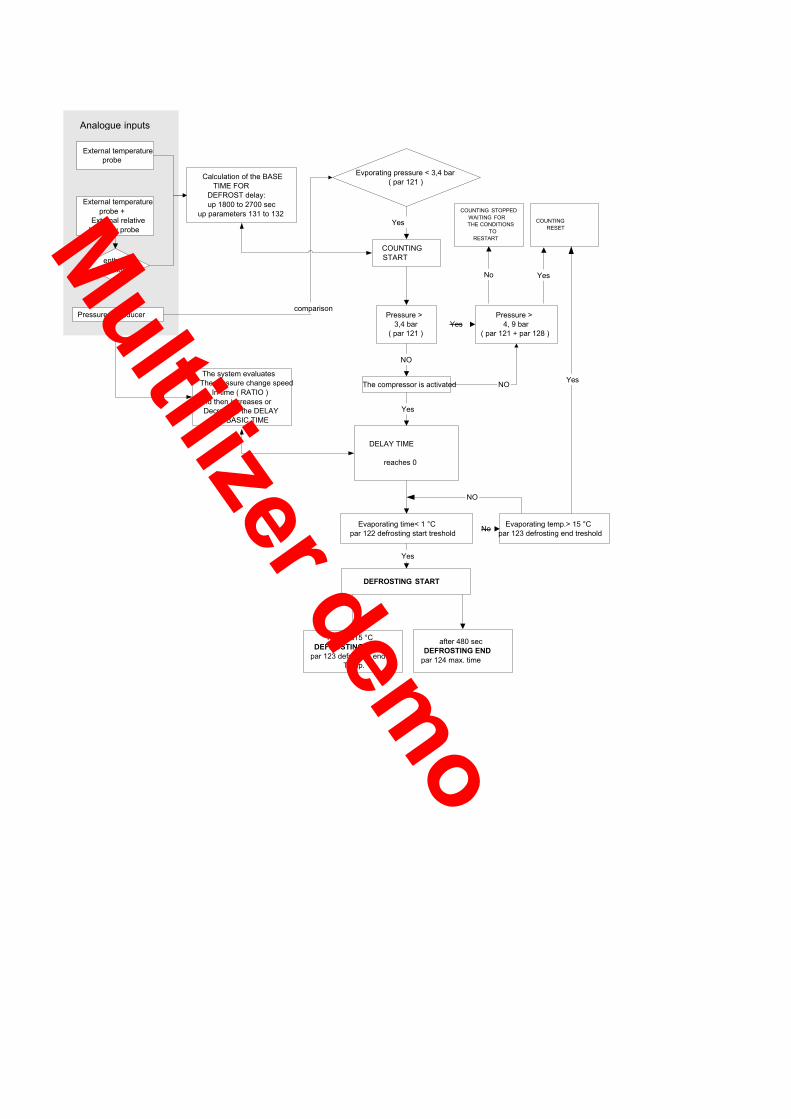
External temperatureprobe
External temperatureprobe +
External relativeHumidity probe
enthalpycalculation
Calculation of the BASETIME FOR
DEFROST delay:up 1800 to 2700 sec
up parameters 131 to 132
Evporating pressure < 3,4 bar( par 121 )
Yes
COUNTINGSTART
Pressure transducer Pressure >3,4 bar
( par 121 )Yes
Pressure >4, 9 bar
( par 121 + par 128 )
COUNTINGRESET
YesNo
DELAY TIME
reaches 0
NO
The compressor is activated NO
Yes
Evaporating time< 1 °Cpar 122 defrosting start treshold
DEFROSTING START
Yes
Evaporating temp.> 15 °Cpar 123 defrosting end tresholdNo
NO
Yes
comparison
Analogue inputs
COUNTING STOPPEDWAITING FORTHE CONDITIONS
TORESTART
reached15 °CDEFROSTING END
par 123 defrosting endTemp.
after 480 secDEFROSTING END
par 124 max. time
The system evaluatesThe pressure change speed
In time ( RATIO )And then increases or
Decreases the DELAYBASIC TIME
Multilizer demo

24 TEMPERATURE CONVERSION TABLE - NTC PROBE HEATER -Temperature Heater Temperature Heater Temperature Heater
-10,0°C 43547Ω 16,0°C 14324Ω 42,0°C 5559Ω
-9,5°C 42543Ω 16,5°C 14046Ω 42,5°C 5466Ω
-9,0°C 41566Ω 17,0°C 13774Ω 43,0°C 5374Ω
-8,5°C 40615Ω 17,5°C 13508Ω 43,5°C 5285Ω
-8,0°C 39689Ω 18,0°C 13249Ω 44,0°C 5197Ω
-7,5°C 38787Ω 18,5°C 12995Ω 44,5°C 5111Ω
-7,0°C 37909Ω 19,0°C 12746Ω 45,0°C 5026Ω
-6,5°C 37054Ω 19,5°C 12503Ω 45,5°C 4943Ω
-6,0°C 36221Ω 20,0°C 12266Ω 46,0°C 4862Ω
-5,5°C 35410Ω 20,5°C 12034Ω 46,5°C 4782Ω
-5,0°C 34619Ω 21,0°C 11806Ω 47,0°C 4704Ω
-4,5°C 33849Ω 21,5°C 11584Ω 47,5°C 4627Ω
-4,0°C 33099Ω 22,0°C 11367Ω 48,0°C 4552Ω
-3,5°C 32368Ω 22,5°C 11154Ω 48,5°C 4478Ω
-3,0°C 31655Ω 23,0°C 10946Ω 49,0°C 4405Ω
-2,5°C 30961Ω 23,5°C 10742Ω 49,5°C 4334Ω
-2,0°C 30284Ω 24,0°C 10543Ω 50,0°C 4264Ω
-1,5°C 29624Ω 24,5°C 10348Ω 50,5°C 4196Ω
-1,0°C 28981Ω 25,0°C 10157Ω 51,0°C 4129Ω
-0,5°C 28353Ω 25,5°C 9970Ω 51,5°C 4063Ω
0,0°C 27742Ω 26,0°C 9787Ω 52,0°C 3998Ω
0,5°C 27146Ω 26,5°C 9608Ω 52,5°C 3934Ω
1,0°C 26564Ω 27,0°C 9433Ω 53,0°C 3872Ω
1,5°C 25997Ω 27,5°C 9261Ω 53,5°C 3810Ω
2,0°C 25444Ω 28,0°C 9093Ω 54,0°C 3750Ω
2,5°C 24904Ω 28,5°C 8929Ω 54,5°C 3691Ω
3,0°C 24378Ω 29,0°C 8768Ω 55,0°C 3633Ω
3,5°C 23864Ω 29,5°C 8610Ω 55,5°C 3576Ω
4,0°C 23363Ω 30,0°C 8456Ω 56,0°C 3520Ω
4,5°C 22874Ω 30,5°C 8305Ω 56,5°C 3465Ω
5,0°C 22397Ω 31,0°C 8157Ω 57,0°C 3411Ω
5,5°C 21931Ω 31,5°C 8012Ω 57,5°C 3358Ω
6,0°C 21477Ω 32,0°C 7870Ω 58,0°C 3306Ω
6,5°C 21033Ω 32,5°C 7730Ω 58,5°C 3255Ω
7,0°C 20600Ω 33,0°C 7594Ω 59,0°C 3205Ω
7,5°C 20177Ω 33,5°C 7461Ω 59,5°C 3156Ω
8,0°C 19764Ω 34,0°C 7330Ω 60,0°C 3107Ω
8,5°C 19361Ω 34,5°C 7202Ω 60,5°C 3060Ω
9,0°C 18967Ω 35,0°C 7076Ω 61,0°C 3013Ω
9,5°C 18583Ω 35,5°C 6953Ω 61,5°C 2967Ω
10,0°C 18208Ω 36,0°C 6832Ω 62,0°C 2922Ω
10,5°C 17841Ω 36,5°C 6714Ω 62,5°C 2878Ω
11,0°C 17483Ω 37,0°C 6598Ω
11,5°C 17133Ω 37,5°C 6485Ω
12,0°C 16791Ω 38,0°C 6374Ω
12,5°C 16457Ω 38,5°C 6264Ω
13,0°C 16131Ω 39,0°C 6158Ω13,5°C 15812Ω 39,5°C 6053Ω14,0°C 15501Ω 40,0°C 5950Ω14,5°C 15196Ω 40,5°C 5849Ω15,0°C 14899Ω 41,0°C 5751Ω15,5°C 14608Ω 41,5°C 5654Ω
Multilizer demo
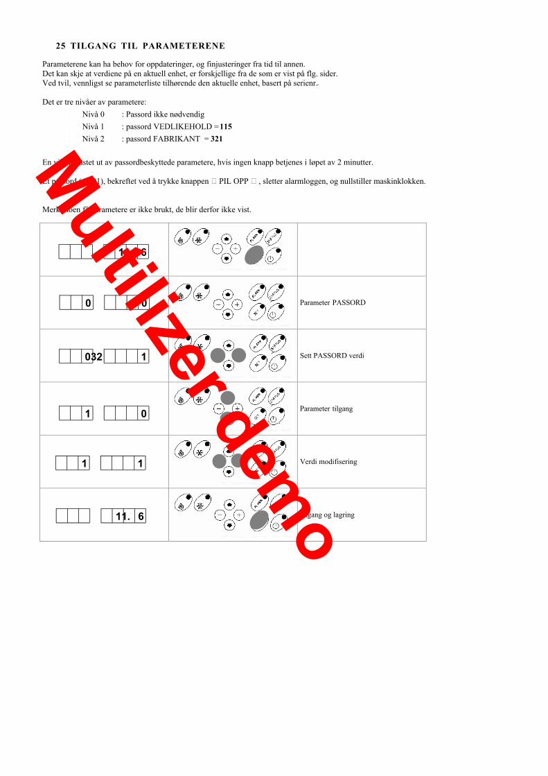
25 TILGANG TIL PARAMETERENE
Parameterene kan ha behov for oppdateringer, og finjusteringer fra tid til annen.Det kan skje at verdiene på en aktuell enhet, er forskjellige fra de som er vist på flg. sider.Ved tvil, vennligst se parameterliste tilhørende den aktuelle enhet, basert på serienr..
Det er tre nivåer av parametere:• Nivå 0 : Passord ikke nødvendig• Nivå 1 : passord VEDLIKEHOLD = 115• Nivå 2 : passord FABRIKANT = 321
En vil bli kastet ut av passordbeskyttede parametere, hvis ingen knapp betjenes i løpet av 2 minutter.
Et passord (= 101), bekreftet ved å trykke knappen �PIL OPP �, sletter alarmloggen, og nullstiller maskinklokken.
Merk: noen få parametere er ikke brukt, de blir derfor ikke vist.
11. 6
Parameter PASSORD
Sett PASSORD verdi
Parameter tilgang
Verdi modifisering
Utgang og lagring
0 0
032 1
1 0
1 1
11. 6Multilizer dem
o

26 PARAMETER LISTE
PARAMETER MENYTastat
urIndex
MnemonicName Beskrivelse Default Psw level Min maks Tenths UM
1ENCCar It enables charged comp. 0=No 1=Cool
2=Heat 3=Always 0 1 0 3 0 only 2= heating only0=None 1=cooling
3=Always
2 CompCarC Max. Summer load compensation 1 2 0 10 1 °C
3 CompCarH Max. Winter load compensation 1 2 0 10 1 °C
4 MediaDelta Time for average on (Ting. � Tout) 300 2 0 999 0 sec
5 MinDeltaC Min. Summer delta temperature 1 2 0 10 1 °C
6 MaxDeltaC Max. Summer delta temperature 4 2 0 10 1 °C
7 MinDeltaH Min. Winter delta temperature 1 2 0 10 1 °C
8 MaxDeltaH Max. Winter delta temperature 4 2 0 10 1 °C
9CompExt Ext.temp. comp. enabling 0=No 1=Cool
2=Heat 3=Always 0 1 0 3 0 only 2= heating only0=None 1=cooling
3=Always
10 CextMaxC Ext. temp. for max. summer correction 15 2 -60 90 0 °C
11 CextMinC Ext. temp. for min. summer correction 30 2 -60 90 0 °C
12 CextMaxH Ext. temp. for max. winter correction 15 2 -60 90 0 °C
13 CextMinH Ext. temp. for min winter correction 0 2 -60 90 0 °C
14 MaxCExtC Max. value of summer correction 8 2 0 25 1 °C
15 MaxCExtH Max. value of winter correction 10 2 0 25 1 °C
16 HExtMinC Ext. enthalpy for min. correction 10,5 2 0 50 0 g/Kg
17 HExtMaxC Ext. enthalpy for max. correction 13,5 2 0 50 0 g/Kg
18WaterReset Water Reset enabling 0=No 1=Cool 2=Heat
3=Always 0 1 0 3 0 only 2= heating only0=None 1=cooling
3=Always
19 MaxCWRH Max. value of WR winter correction 10 2 0 15 1 °C
20 SWRMAXH Signal corresponding to Max. wintercorrection 4 2 4 20 0 mA
21 SWRMinH Signal corresponding to Min. wintercorrection 20 2 4 20 0 mA
22 MaxCWRC Max. value of WR correction in summeroperation 8 2 0 15 1 °C
23 SWRMaxC Signal corresponding to Max. WR in summeroperation 20 2 4 20 0 mA
24 SWRMinC Signal corresponding to Min. WR in summeroperation 4 2 4 20 0 mA
25 MaxSetHeat MAX Set Heat 51 2 -60 90 1 °C
26 MinSetHeat Min Set Heat 22 2 -60 90 1 °C
27 MaxSetCool Max Set Cool 21 2 -60 90 1 °C
28 MinSetCool Min Set Cool 5 2 -60 90 1 °C
29 SecondSetC Secondary summer SetPoint 10 0 -60 90 1 °C
30 SecondSetH Secondary winter SetPoint 35 0 -60 90 1 °C
31 Set2EN Enables second Set Point 0 1 0 1 0 1=YES / 0=NO
32 SetCool Summer Set Point 5,7 0 -30 60 1 °C
33 SetHeat Winter Set Point 41,2 0 -30 60 1 °C
34 TScanMax Max. activation scann time 600 2 0 9999 0 secMultilizer dem
o
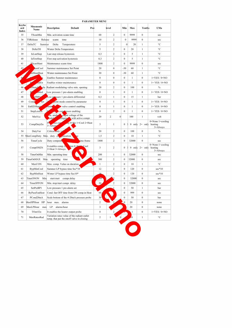
PARAMETER MENUKeybo
ardIndex
MnemonicName Description Default Psw level Min Max Tenths UMa
35 TScanMin Min. activation scann time 60 2 0 9999 0 sec
36 TSRelease Release scann time 10 2 0 9999 0 sec
37 DeltaTC Summer Delta Temperature 5 2 0 20 1 °C
38 DeltaTH Winter Delta Temperature 5 2 0 20 1 °C
39 IsLastStep Last step release hysteresis 0,3 2 0 5 1 °C
40 IsFirstStep First step activation hysteresis 0,3 2 0 5 1 °C
41 TScanMant Maintenance scann time 1800 2 0 9999 0 sec
42 SetMantCool Summer maintenance Set Point 20 0 -30 60 1 °C
43 SetMantHeat Winter maintenance Set Point 30 0 -30 60 1 °C
44 MantCoolEn Enables Summer maintenance 0 0 0 1 0 1=YES / 0=NO
45 MantHeatEn Enables winter maintenance 0 0 0 1 0 1= YES / 0=NO
46 MinStatoValvola Radiant modulating valve min. opening 20 2 0 100 0 %
47 BP1Enabled Low pressure 1 pre-alarm enabling 0 1 0 1 0 1= YES / 0=NO
48 DiffBP1 Low pressure 1 pre-alarm differential 0,3 1 0 15 1 bar
49 Comando2°Set 2° set point mode control by parameter 0 1 0 1 0 1= YES / 0=NO
50 EnH2OSanitaria Sanitary water valve control enabling 0 1 0 1 0 1= YES / 0=NO
51 StepLessEn Modulatine compressor enabling 0 2 0 1 0 1= YES / 0=NO
52 MinVcc Min. analogic output voltage of themodulating compressor with active compr. 20 2 0 100 1 volt
53 CompDutyEn It enables comp. Duty 0=No 1=Cool 2=Heat3=Always 3 1 0 3 0 only 2= only heating
0=None 1=cooling
3=Always54 DutyVar Critical duty value 20 2 0 100 0 %
55 MaxCompDuty Max. duty compensation value 1,5 2 0 10 1 °C
56 TimeCycle Duty compensation calculation time frame 1800 2 0 32000 0 sec
57 CompONEN It enables comp. Duration 0=No 1=Cool2=Heat 3=Always 3 2 0 3 0 only 2= only heating
0=None 1=cooling
3=Always58 TimeOnMin Min. operating time 200 1 0 32000 0 sec
59 TimeOnMAX Max. operating time 300 2 0 32000 0 sec
60 MaxCON Max. comp. Value on duration 1 2 0 10 1 °C
61 BypMinCool Summer LP bypass time Sec*10 12 2 0 120 0 sec*10
62 BypMinHeat Winter LP bypass time Sec10* 18 2 0 120 0 sec*10
63 TimeONON Min. start/start compr.delay 360 2 0 32000 0 sec
64 TimeOFFON Min. stop/start compr. delay 30 2 0 32000 0 sec
65 SetPreBP1 Low pressure 1 pre-alarm set 3,5 1 0 50 1 bar
66 ByPassFanHeat Cond. fan OFF time from ON comp.in Heat 60 2 0 999 0 sec
67 PCond20mA Scale bottom of the 4-20mA pressure probe 30 2 0 50 0 bar
68 MaxHPHour HP hour max. alarms 2 2 0 20 0 none
69 MaxLPHour max LP alarms/hour 3 2 0 20 0 none
70 TOut1En It enables the heater output probe 0 2 0 1 0 1=YES / 0=NO
71 MaxRateoRad Variation rateo value of the radiant outlettemp. that put the onoff valve in closing 2 1 0 10 1 °C
Multilizer demo

PARAMETER MENUKeybo
ardIndex
MnemonicName Description Default Psw level Min Max Tenths UMa
72 PotC1 Compressor1 capacity percentage 1 100 2 0 100 0 %
73 EnLimiteTExtH SP Heat corr. Enabling for external air limit 0 2 0 1 0 1=YES / 0=NO
74 TlimiteMaxH External temperature for max SP Heat -5 2 -60 90 0 °C
76 ScanPreAF PreFreeze scann time 10 2 0 9999 0 sec
77 SetHeater Antifreeze heater set point 4 0 -60 90 1 °C
78 MinFreeze Min. level antifreeze alarm 4 2 -60 90 1 °C
79 MaxFreeze Max. level antifreeze alarm 15 2 -60 90 1 °C
80 AlFreeze Antifreeze alarm set 4 0 -60 90 1 °C
81 DiffHeater Antifreeze heater differential 2,5 1 0 15 1 °C
82 IsPreAF Antifreeze Pre-alarm hysteresis 1 2 0 15 1 °C
83 IstAlFreeze Antifreeze Alarm hysteresis 2,5 2 0 15 1 °C
84 PreAF Antifreeze pre-alarm set 4,5 0 0 15 1 °C
91 FanPFCorr Fan phase factor correction 3800 1 0 32000 0 1=500ns
92 ONFanCool FAN start pressure with comp. Off summer 17 1 -60 90 1 bar
93 ONFanHeat FAN start pressure with comp. Off winter 0 1 -60 90 1 bar
94 MaxFanHeat Pressure for max fan speed heat. 3,7 1 -60 90 1 bar
95 MinFanHeat Pressure for min fan speed heat 4,2 1 -60 50 1 bar
96 MaxFanCool Pressure for max fan speed cool 17 1 -60 50 1 bar
97 MinFanCool Pressure for min fan speed cool 13,5 1 -60 50 1 bar
98 CutOffHeat Fan Cut-OFF heat 4,8 1 -60 50 1 bar
99 CutOffCool Fan Cut-OFF cool 12 1 -60 50 1 bar
100 TstartUp Pulse duration at fan start 5 1 0 120 0 sec
101 TbypCutOf Cut-off by-pass duration 25 1 0 120 0 sec
102 MaxFan Max % Fan 70 1 0 100 0 %
103 MinFan Min % Fan 40 1 0 100 0 %
104 MaxStartUp % Fan at start pulse 70 1 0 100 0 %
105 ToutEn It enables the evaporator outlet temp. probe 1 2 0 1 0 1=YES / 0=NO
106 TypeCECondensing time 0=In Air 1=In Water2=Temp. Control in heat for unit reversibleon water
0 2 0 2 0 none
107 TimeOffV Water flow by-pass time 0 1 0 120 0 sec
111 HP1Enabled Enables HP1 Prealarm 0 1 0 1 0 1=YES / 0=NO
112 SMaxPreC Summer HP1 Prealarm Set 24,5 1 0 50 1 bar
113 DiffMaxPreC Summer HP1 Prealarm Hysteresis 2 1 0 15 1 bar
114 ByPassFreeze ByPassAntifreeze alarm 120 1 0 32000 0 sec
117 SetH2OSanitaria Sanitary water set point 35 0 -60 90 1 °C
118 TempoCorrezione Radiant correction time 20 1 0 999 0 sec
119 ModeEnable It sets the operating modes 0 2 0 4 0 none
120 TmaxRicircolo Radiant valve max. time in recirculationposition 800 2 10 990 0 min
121 PstartDfr Defrost start press. 3,4 1 0 50 1 bar
122 TstartDfr Defrost start temp. 1 1 -10 30 1 °C
Multilizer demo

PARAMETER MENUKeybo
ardIndex
MnemonicName Description Default Psw level Min Max Tenths UMa
123 TstopDfr Defrost stop. Temp. 15 2 -10 30 1 °C
124 TmaxDfr Defrost max. time 480 2 0 32000 0 sec
125 TimeInDfr Defrost start max. time 2700 2 0 32000 0 sec
126 Ttransient Defrost transient time 90 2 0 32000 0 sec
128 DeltaPDfr Defrost delta press. 1,5 1 0 30 1 bar
129 MaxCnt Max. counting IN defrost 4 2 0 10 0 none
130 RateoMaxP Max. pressure ratio 1 2 0 30 1 bar/min
131 TminCntDfr Min. defrost. counting time 1800 2 0 32000 0 sec
132 TmaxCntDfr Max. defrost. counting time 2700 2 0 32000 0 sec
133 TextMinDly External temperature for minimum delay 5 2 -10 30 1 °C
134 TextMaxDly External temperature for maximum delay -10 2 -10 30 1 °C
135 TimeDrain Drop time 60 1 0 900 0 sec
136 TimeFanDfr Fan time after defrost 15 1 0 900 0 sec
137 TExtDfr Extern. temperature for fan start after defrost 3 1 -10 30 1 °C
138 PFDfr Defrost forcing pressure 1,4 1 0 50 1 bar
140 PlugInEN Plug-in presence 1 2 0 1 0 1=YES / 0=NO
141 SecondPump board 1=Single pump+reserve 2=VariableSecond pump presence 0=Single pump on
pump0 2 0 2 0 none
142 ByPassFlusso Flow by-pass from pump start 25 1 0 32000 0 sec
143 RitComp Comp. start delay from pump On 25 1 0 32000 0 sec
144 TStartPump Maintenance pump start time 120 1 0 32000 0 sec
145 DlyPumpC Pump switch-off delay from comp. OFF 120 2 0 32000 0 sec
146 OffsetBTIn Inlet temp.Offset 0 1 -10 10 1 °C
147 OffsetBT1 Outlet 1 temp.Offset 0 1 -10 10 1 °C
148 OffsetPR Radiating panel water temperature Offset 0 1 -10 10 1 °C
149 OffsetBT3 Coil 1 temp.Offset 0 1 -10 10 1 °C
150 OffsetBTRe Electric heater output temp. offset 0 2 -10 10 1 °C
151 OffsetWR Offset Water Reset 0 1 -100 100 0 mA
152 TextEn EXT air probe presence 1 1 0 1 0 1=YES / 0=NO
153 OffsetBTE Offset external temperature 0 1 -10 10 1 °C
154 OffsetBP1 Offset pressure 1 0 1 -10 10 1 bar
155 OffsetURExt Offset Ext RH 0 1 -10 10 1 %
156 URProbeExt Enables external RH% probe 0 1 0 1 0 1=YES / 0=NO
157 OffsetPCWBAN WBAN condensing pressure offset 0 1 -10 10 1 bar
158 TextOnFanCool Threshold of fan Start ext. temperature atstopped compressor 43 1 -30 90 0 °C
159 ProbeCondEn Selection of the type of condensation probe 2 2 0 3 0 none
160 TlimiteMinH Ext. Temperature for min SP Heat -15 2 -60 90 0 °C
161 ValveMode Cycle reversing valve polarity 0 2 0 1 0 flag
162 HeatPump Configurate unit as CHILLER (0)HEATPUMP (1) 1 2 0 1 0 flag
163 RemMode Remote input setting 0=H/C from ID 1=H/Cfrom keypad or supervisor 0 0 0 1 0 flag
Multilizer demo

PARAMETER MENUKeybo
ardIndex
MnemonicName Description Default Psw level Min Max Tenths UMa
164 Address ModBus serial address 55 2 0 127 0 none
165 Baud Rate Baud Rate (0=4800 / 1=9600) 0 2 0 1 0 flag
166 Parity Parity 0=NO / 1=YES 0 2 0 1 0 flag
169 TDeltaChiller Water delta for the calculation of the wateroutlet control threshold 2 1 -20 20 0 °C
173 TPompaMax Max. flow-rate activation timer 20 2 0 999 0 sec
175 MinSetLimiteH Min. settable value for the SP Heat 35 2 -30 90 1 °C
176 CANAddressNode CANOPEN board address 1 1 0 127 0 none
177 PotRes Output by the integration heaters 100 2 0 100 0 %
178 ModeHeater Compressor oper. enabling in heating 0 2 0 2 0 none
179 LimPotTextEn Power limit enabling for ext. temperature. 0 2 0 2 0 none
180 LimText Ext. temperature limit for compressoroperation 0 2 -30 30 0 °C
181 IstRes Differential on the LimText value foractivating the heaters 5 2 2 20 0 °C
182 Tregime Heaters Timeout 1200 1 0 10000 0 sec
183 MaxTempC COOLING delivery decrease threshold 15 2 0 90 1 °C
184 MinTempH HEATING delivery decrease threshold 15 2 0 90 1 °C
185 IstTempC Cooling delivery decrease hysteresis 8 2 0 15 1 °C
186 IstTempH Heating delivery decrease hysteresis 5 2 0 15 1 °C
187 MinSignal Pump signal corresponding to max. deliverydecrease 60 2 0 100 0 %
188 MaxSignal Pump signal corresponding to rated delivery 100 2 0 100 0 %
189 StepType Modality of variable pump step insertion 1 2 0 1 0 flag
190 EnCompExtR External temperature radiating compensationenabling 0 1 0 1 0 1= YES / 0=NO
191 EnCompRugiada Enables the compensation for dew in cooling 0 1 0 1 0 1=YES / 0=NO
192 SetPointR Radiating set-point 25 2 -60 90 1 °C
194 SetMinC Differential for radiating set-point 18 2 -60 90 0 °C
195 SetMaxC Min. set-point in cooling 23 2 -60 90 0 °C
196 TMinExtC Max. set-point in cooling 20 2 -60 90 0 °C
197 TmaxExtC Min. summer temperature in cooling 35 2 -60 90 0 °C
198 SetMinH Max. summer temperature in cooling 30 2 -60 90 0 °C
199 SetMaxH Min. set-point in heating 35 2 -60 90 0 °C
200 TMinExtH Max. set-point in heating 5 2 -60 90 0 °C
201 TMaxExtH Min. external temperature heating 20 2 -60 90 0 °C
202 TPannRadEn Max. external temperature heating 0 2 0 1 0 1=YES / 0=NO
203 EnPCondPlugIn It enables and sets F.S. WBAN condensingpress. probe 0 1 0 50 0 bar
204 PumpPFCorr Evaporator pump power factor correction 3800 1 0 32000 0 1=500ns
205 TempAperturaValv Necessary time to position the VRad fromclosed to completely opened 90 1 0 999 0 sec
206 BandaApertura It allows to weigh the valve opening time 200 1 100 1000 0 none
207 MaxInteg when activated at the same time of theMax. value of the integration heater outputs
compressor100 1 0 100 1 %
208 SetfreezeExt Source water temp. threshold for the Coilfreeze alarm activation 4 1 -30 90 1 °C
209 SetHeaterExt Source water temp. Threshold for theantifreeze heater activation 4 1 -30 90 1 °C
210 SetValvolaOn Activation threshold of the defrosting valve athot gas 28,5 1 0 50 10 bar
Multilizer demo

70
PARAMETER MENUKeybo
ardIndex
MnemonicName Description Default Psw level Min Max Tenths UMa
211 DiffValvolaOn Differential for the reset in OFF of thedefrosting valve at hot gas 1,5 1 0 50 10 bar
212 TimerPCondOn manages the DFR valve at hot gas in base ofActive timer from ON compressor that
the critical pressure thresholds300 1 0 900 1 sec
213 AddTast Keypad address 7=Local 1=Remote 7 0 0 127 0 none
Multilizer demo

www.clivet.com
The information contained in this manual is not binding and may be changed by the manufacturer without prior notice.All copying, even partial, is prohibited.
Multilizer demo