Embed Size (px)
Citation preview

X5 GSM Control & Monitoring SystemsX5 GSM Control & Monitoring SystemsX5 GSM Control & Monitoring SystemsX5 GSM Control & Monitoring Systems
Installation and Setup ManualInstallation and Setup ManualInstallation and Setup ManualInstallation and Setup Manual
Firmware F5.03Firmware F5.03Firmware F5.03Firmware F5.03
GSM850MHz, GSM900MHzGSM850MHz, GSM900MHzGSM850MHz, GSM900MHzGSM850MHz, GSM900MHz
DCS1800MHz & PCS1900MHzDCS1800MHz & PCS1900MHzDCS1800MHz & PCS1900MHzDCS1800MHz & PCS1900MHz
OpenOpenOpenOpen----onononon----Call Access ControlCall Access ControlCall Access ControlCall Access Control Alarm Dialer & SMS SenderAlarm Dialer & SMS SenderAlarm Dialer & SMS SenderAlarm Dialer & SMS Sender Remote Voltage MonitoringRemote Voltage MonitoringRemote Voltage MonitoringRemote Voltage Monitoring
Remote Relay ControlRemote Relay ControlRemote Relay ControlRemote Relay Control
www.adventcontrols.co.ukwww.adventcontrols.co.ukwww.adventcontrols.co.ukwww.adventcontrols.co.uk
Contents
1 Introduction 3 1.1 Product Selection an d Specification 3 1.2 Number Types 4 2 Numbers and Startup 5 2.1 Registration 5 2.2 Command Message Format 5 2.3 Master Number Setup 6 2.4 Allowing Master Control for All Users 7 2.5 Adding a User Number 7 2.6 Removing a User Number 7 2.7 Viewing the Valid Number List 8 2.8 Finding a Number in the Memory 9 2.9 Clearing All Numbers and Settings 9 2.10 Result Acknowledgement Message 9 3 General Setup 10 3.1 Input-Output Status Message 10 3.2 PAYG SIM Keep Alive 10 3.3 Signal Strength Indicator 11 3.4 Power Up/Reset Text Message 12 3.5 SIM Card Balance Checking and Service Data Forwarding 12 3.6 Forwarding SMS Messages to any Number 12 3.7 Inverting the Relay Output 13 3.8 Input A Relay Control 13 4 Relay Operation/Access Control 14 4.1 Enabling Any Number and Disabling Open-on-Call 14 4.2 Call Reject 14 4.3 Connecting a Call 14 4.4 Relay Activation Mode 15 4.5 Relay Activation Time 15 4.6 OPEN/ON & CLOSE/OFF Commands 15 4.7 Exit Switch Enable 16 4.8 Output Change Acknowledge SMS 16 5 Auto-Dialler/SMS Sender 17 5 Input Triggered SMS Text Sending and Auto-Dialling 17 5.1 Enabling and Disabling Inputs 17 5.2 Input Change State Level 18 5.3 Customising the Input Alert Message 19 5.4 Autodial Logic 19 5.5 Changing the Maximum Ring Time 19 5.6 Changing the Maximum Call Time 20 5.7 Changing the Maximum Silence Time 20 5.8 Adding SMS Sender Text Numbers 20 5.9 Adding Auto-Dialler Call Numbers 20 5.10 Assigning a Number to One Channel Only 20 5.11 International Calling/Texting 21 5.12 Dial Now 21 5.13 Input Hold-off Timer 21 5.14 Repeating the SMS/Call 21 5.15 Silencing the Alarm 21 6 Analogue Voltage Measurements 22 6.1 Setting the Upper Voltage Threshold Voltage 22 6.2 Setting the Lower Voltage Threshold Voltage 22 7 GPRS Software PC Connection 23 7.1 Specifying the Access Point Name (APN) 23 7.2 Initiating a PC Connection 23 8 Installation 24 8.1 Power Connection 24 8.2 Input Connection 25 6.3 Connection to a Burglar Alarm 25 6.4 Output Connection 26 6.5 Antenna Connection 27 6.5 Mounting 27 9 Command Set Summary 28
1. Introduction
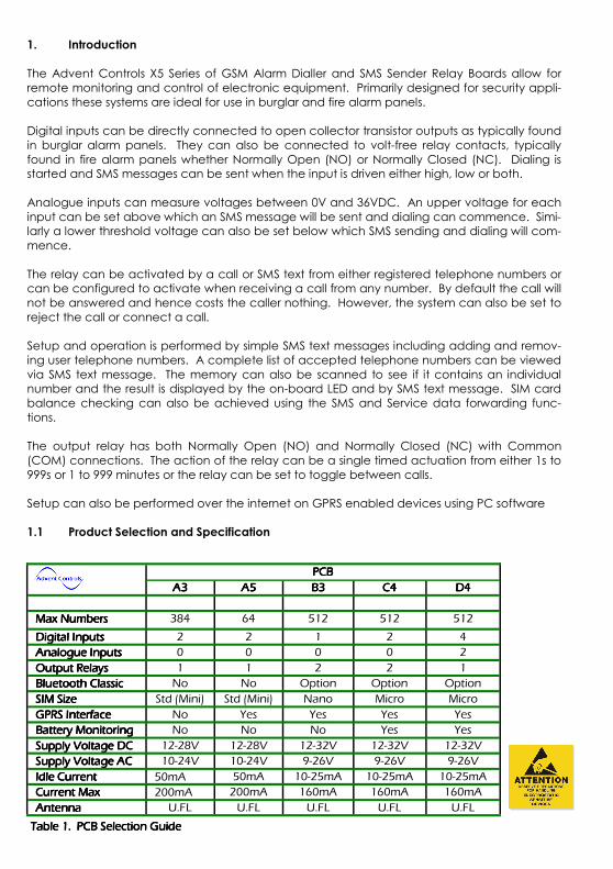
The Advent Controls X5 Series of GSM Alarm Dialler and SMS Sender Relay Boards allow for remote monitoring and control of electronic equipment. Primarily designed for security appli-cations these systems are ideal for use in burglar and fire alarm panels. Digital inputs can be directly connected to open collector transistor outputs as typically found in burglar alarm panels. They can also be connected to volt-free relay contacts, typically found in fire alarm panels whether Normally Open (NO) or Normally Closed (NC). Dialing is started and SMS messages can be sent when the input is driven either high, low or both. Analogue inputs can measure voltages between 0V and 36VDC. An upper voltage for each input can be set above which an SMS message will be sent and dialing can commence. Simi-larly a lower threshold voltage can also be set below which SMS sending and dialing will com-mence. The relay can be activated by a call or SMS text from either registered telephone numbers or can be configured to activate when receiving a call from any number. By default the call will not be answered and hence costs the caller nothing. However, the system can also be set to reject the call or connect a call. Setup and operation is performed by simple SMS text messages including adding and remov-ing user telephone numbers. A complete list of accepted telephone numbers can be viewed via SMS text message. The memory can also be scanned to see if it contains an individual number and the result is displayed by the on-board LED and by SMS text message. SIM card balance checking can also be achieved using the SMS and Service data forwarding func-tions. The output relay has both Normally Open (NO) and Normally Closed (NC) with Common (COM) connections. The action of the relay can be a single timed actuation from either 1s to 999s or 1 to 999 minutes or the relay can be set to toggle between calls. Setup can also be performed over the internet on GPRS enabled devices using PC software 1.1 Product Selection and Specification
PCBPCBPCBPCB
A3A3A3A3 A5A5A5A5 B3B3B3B3 C4C4C4C4 D4D4D4D4
Max NumbersMax NumbersMax NumbersMax Numbers 384 64 512 512 512
Digital InputsDigital InputsDigital InputsDigital Inputs 2 2 1 2 4
Analogue InputsAnalogue InputsAnalogue InputsAnalogue Inputs 0 0 0 0 2
Output RelaysOutput RelaysOutput RelaysOutput Relays 1 1 2 2 1
Bluetooth ClassicBluetooth ClassicBluetooth ClassicBluetooth Classic No No Option Option Option
SIM SizeSIM SizeSIM SizeSIM Size Std (Mini) Std (Mini) Nano Micro Micro
GPRS InterfaceGPRS InterfaceGPRS InterfaceGPRS Interface No Yes Yes Yes Yes
Battery MonitoringBattery MonitoringBattery MonitoringBattery Monitoring No No No Yes Yes
Supply Voltage DCSupply Voltage DCSupply Voltage DCSupply Voltage DC 12-28V 12-28V 12-32V 12-32V 12-32V
Supply Voltage ACSupply Voltage ACSupply Voltage ACSupply Voltage AC 10-24V 10-24V 9-26V 9-26V 9-26V
Idle CurrentIdle CurrentIdle CurrentIdle Current 50mA 50mA 10-25mA 10-25mA 10-25mA
Current MaxCurrent MaxCurrent MaxCurrent Max 200mA 200mA 160mA 160mA 160mA
AntennaAntennaAntennaAntenna U.FL U.FL U.FL U.FL U.FL
Table 1. PCB Selection GuideTable 1. PCB Selection GuideTable 1. PCB Selection GuideTable 1. PCB Selection Guide
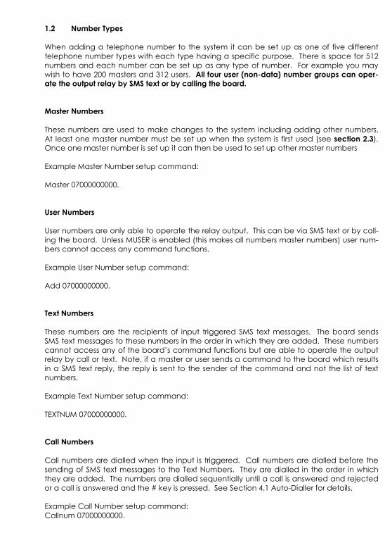
1.2 Number Types
When adding a telephone number to the system it can be set up as one of five different telephone number types with each type having a specific purpose. There is space for 512 numbers and each number can be set up as any type of number. For example you may wish to have 200 masters and 312 users. All four user (non-data) number groups can oper-ate the output relay by SMS text or by calling the board.
Master Numbers
These numbers are used to make changes to the system including adding other numbers. At least one master number must be set up when the system is first used (see section 2.3). Once one master number is set up it can then be used to set up other master numbers Example Master Number setup command: Master 07000000000.
User Numbers
User numbers are only able to operate the relay output. This can be via SMS text or by call-ing the board. Unless MUSER is enabled (this makes all numbers master numbers) user num-bers cannot access any command functions. Example User Number setup command: Add 07000000000. Text Numbers
These numbers are the recipients of input triggered SMS text messages. The board sends SMS text messages to these numbers in the order in which they are added. These numbers cannot access any of the board’s command functions but are able to operate the output relay by call or text. Note, if a master or user sends a command to the board which results in a SMS text reply, the reply is sent to the sender of the command and not the list of text numbers. Example Text Number setup command: TEXTNUM 07000000000. Call Numbers
Call numbers are dialled when the input is triggered. Call numbers are dialled before the sending of SMS text messages to the Text Numbers. They are dialled in the order in which they are added. The numbers are dialled sequentially until a call is answered and rejected or a call is answered and the # key is pressed. See Section 4.1 Auto-Dialler for details. Example Call Number setup command: Callnum 07000000000.
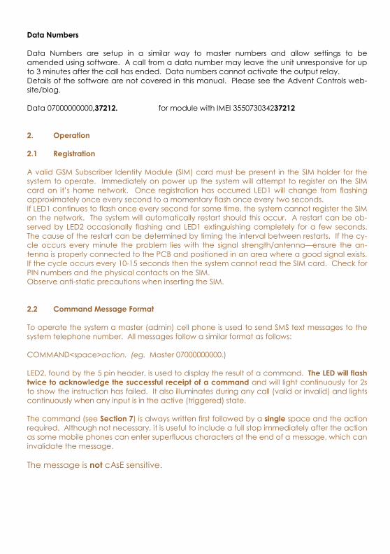
Data Numbers
Data Numbers are setup in a similar way to master numbers and allow settings to be amended using software. A call from a data number may leave the unit unresponsive for up to 3 minutes after the call has ended. Data numbers cannot activate the output relay. Details of the software are not covered in this manual. Please see the Advent Controls web-site/blog. Data 07000000000,37212. for module with IMEI 355073034237212
2. Operation
2.1 Registration
A valid GSM Subscriber Identity Module (SIM) card must be present in the SIM holder for the system to operate. Immediately on power up the system will attempt to register on the SIM card on it’s home network. Once registration has occurred LED1 will change from flashing approximately once every second to a momentary flash once every two seconds. If LED1 continues to flash once every second for some time, the system cannot register the SIM on the network. The system will automatically restart should this occur. A restart can be ob-served by LED2 occasionally flashing and LED1 extinguishing completely for a few seconds. The cause of the restart can be determined by timing the interval between restarts. If the cy-cle occurs every minute the problem lies with the signal strength/antenna—ensure the an-tenna is properly connected to the PCB and positioned in an area where a good signal exists. If the cycle occurs every 10-15 seconds then the system cannot read the SIM card. Check for PIN numbers and the physical contacts on the SIM. Observe anti-static precautions when inserting the SIM. 2.2 Command Message Format
To operate the system a master (admin) cell phone is used to send SMS text messages to the system telephone number. All messages follow a similar format as follows: COMMAND<space>action. (eg. Master 07000000000.) LED2, found by the 5 pin header, is used to display the result of a command. The LED will flash
twice to acknowledge the successful receipt of a command and will light continuously for 2s to show the instruction has failed. It also illuminates during any call (valid or invalid) and lights continuously when any input is in the active (triggered) state. The command (see Section 7) is always written first followed by a single space and the action required. Although not necessary, it is useful to include a full stop immediately after the action as some mobile phones can enter superfluous characters at the end of a message, which can invalidate the message. The message is not cAsE sensitive.
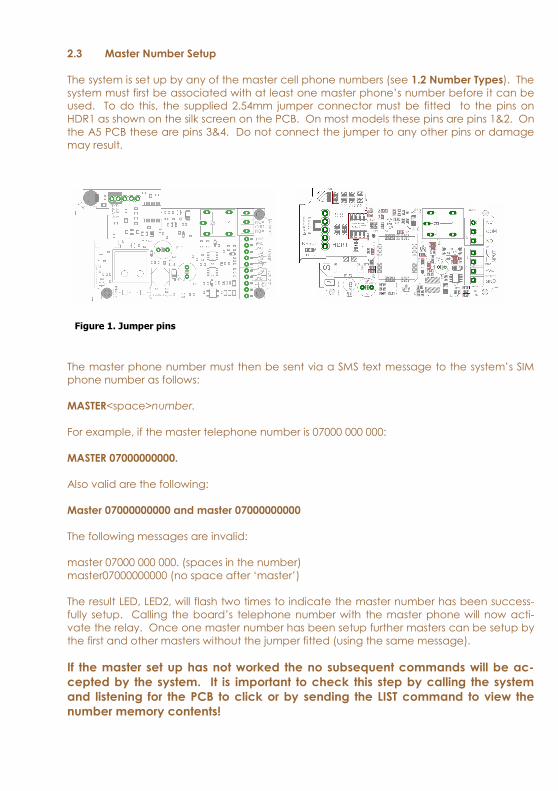
2.3 Master Number Setup
The system is set up by any of the master cell phone numbers (see 1.2 Number Types). The system must first be associated with at least one master phone’s number before it can be used. To do this, the supplied 2.54mm jumper connector must be fitted to the pins on HDR1 as shown on the silk screen on the PCB. On most models these pins are pins 1&2. On the A5 PCB these are pins 3&4. Do not connect the jumper to any other pins or damage may result.
The master phone number must then be sent via a SMS text message to the system’s SIM phone number as follows:
MASTER<space>number.
For example, if the master telephone number is 07000 000 000:
MASTER 07000000000.
Also valid are the following: Master 07000000000 and master 07000000000
The following messages are invalid: master 07000 000 000. (spaces in the number) master07000000000 (no space after ‘master’) The result LED, LED2, will flash two times to indicate the master number has been success-fully setup. Calling the board’s telephone number with the master phone will now acti-vate the relay. Once one master number has been setup further masters can be setup by the first and other masters without the jumper fitted (using the same message). If the master set up has not worked the no subsequent commands will be ac-
cepted by the system. It is important to check this step by calling the system
and listening for the PCB to click or by sending the LIST command to view the
number memory contents!
Figure 1. Jumper pins
Using the PIN for Master Setup
The Master Number can also be set up using the PIN. This is only possible for the first master number that is added to the system. Subsequent masters must be added by a master using the MASTER command. The PIN is the last 5 characters of the IMEI number written on the QUECTEL GSM module sticker. The command is sent as follows: Master 07000000000,37212. for module with IMEI 355073034237212
2.4 Allowing Master Control for all Users
To enable any user to control master commands (such as adding and removing numbers) the MUSER command is sent to the board, by a master number, as follows: MUSER ENABLE Allows any valid user number to modify settings MUSER DISABLE Only master numbers can modify settings By default MUSER is set to disable full access for all users. N.B. Only master numbers can add other master numbers despite this setting
2.5 Adding a User Number
Any telephone number of at least 5 digits where caller ID is available is valid. The system only compares the last 8 digits (if present) of any calling number against the numbers stored in memory. Therefore it is not necessary to enter the international dialling code format of the telephone number. i.e. for 07000000000 only the characters shown in BOLD text are considered The ADD command is used to add a new telephone number. To add a new number any master phone must send the following SMS text message to the system telephone number: add<space>number. e.g. Add 07000000000. If TEXTRES is enabled the system will respond with the ‘Operation Successful’ message. 2.6 Removing a User Number
The REMOVE command is used to remove an existing telephone number. To remove an existing telephone number any master phone must send the following SMS text message: remove<space>number. e.g. REMOVE 07000000000.
The REMOVE command must be sent for each number in the memory. The user can specify which number type is desired to be removed and only that type will be removed regardless of whether the number is already in the memory in a different form.
For example to remove a Call Number the ‘C’ character is appended after the word remove as follows: REMOVEC 07574163361. This will only remove instances of the number 07574163367 that are stored as Call Num-bers. The following shows the characters associated with each number type: T—Text Number C—Call Number M—Master Number D—Data Number None specified—Any number (including User Numbers) If TEXTRES is enabled the system will respond with the ‘Operation Successful’ message. If the number is not found the ‘Operation Failed’ message will be sent by the system.
2.7 Viewing the Valid Number List
The system can send a SMS text message containing a complete list of valid user numbers to any master phone. To receive the list of numbers the LIST command is used. The master phone must send the following SMS text message to the system: List
The response format shows the number type, the channel (if applicable) and the last 8 digits of the stored number followed by a space and the next number and so on… Number Types: T—Text Number C—Call Number M—Master Number U—User Number D—Data Number K—Keep Alive Number Input Channels: A—Channel A B—Channel B M—Multiple (Both A&B) The numbers are in the reverse order to the order they were added. e.g. TA74163367 CM17283167 D51953899 U17283167 M30666575 07574163367 is a Text Number for Channel A 01517283167 is a Call Number for both channels and so on...
2.8 Finding a Number in the Memory
When a large number of numbers are stored in the memory using the LIST command can be impractical. To find whether an individual number is stored in the memory the master user sends the following command to the board: QUERY<space>number. or QNUM<space>number
NB the number should be the full number (not the 8-digit truncated number)
If the number is present the LED will flash 4 times and if not in the memory the LED will light twice for 2 seconds. If TEXTRES is enabled an SMS text message will be sent with the result.
2.9 Clearing All Numbers and Settings
The CLEAR ALL command is used to erase all stored user and master numbers. To erase all numbers the following SMS text message is sent by a master number: CLEAR ALL
No response is sent by the system to acknowledge the command. This does not earse the customisable input text messages.
2.10 Result Acknowledgement Message
The system can be setup to send a SMS text message to acknowledge a command. This acknowledges the result of the last command processed such as adding a new user num-ber. The SIM card in the system must have sufficient credit for sending SMS text messages. To enable/disable the service the following text message is sent by the master number: TEXTRES enable (or also valid: TEXTRES e) TEXTRES DISABLE (or also valid: TEXTRES d)
The result message ‘Operation Successful’ is sent when the service is enabled
Notes
3 General Setup
3.1 Input/Output Status Message
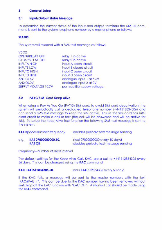
To determine the current status of the input and output terminals the STATUS com-mand is sent to the system telephone number by a master phone as follows: STATUS
The system will respond with a SMS text message as follows: V5.XX OPEN#RELAY OFF relay 1 in-active CLOSE*RELAY OFF relay 2 in-active INPUTA HIGH input A open circuit INPUTB LOW input B closed circuit INPUTC HIGH input C open circuit INPUTD HIGH input D open circuit AN1 05.6V analogue input 1 at 5.6V AN2 00.0V analogue input 2 at 0V SUPPLY VOLTAGE 10.7V post rectifier supply voltage 3.2 PAYG SIM Card Keep Alive
When using a Pay As You Go (PAYG) SIM card, to avoid SIM card deactivation, the system will periodically call a dedicated telephone number (+441512834306) and can send a SMS text message to keep the SIM active. Ensure the SIM card has suffi-cient credit to make a call or text (the call will be answered and will be active for 15s). To setup the Keep Alive Text function the following SMS text message is sent to the system: KAT<space>number,frequency. enables periodic text message sending e.g. KAT 07000000000,10. (text 07000000000 every 10 days) KAT Off disables periodic text message sending Frequency—number of days interval The default settings for the Keep Alive Call, KAC, are a call to +441512834306 every 56 days. This can be changed using the KAC command: KAC +441512834306,50. dials +441512834306 every 50 days If the KAC fails, a message will be sent to the master numbers with the text ‘KAC#FAIL :(“. This can be due to the KAC number having been removed without switching off the KAC function with ‘KAC OFF’. A manual call should be made using the DIAL command.
3.3 Signal Strength Indicator
When setting up the system it is important to know the strength of signal for reliable opera-tion. To receive a message showing the Received Signal Strength Indicator (RSSI) the CSQ command is sent to the system as follows: CSQ
When the system SIM card has sufficient credit a SMS text message is sent to the number which sent the command displaying the current RSSI. e.g. >RSSI 21 It is recommended that the minimum signal level for the installation is 12 (-83dBm) to en-sure reliable operation. The system will operate below 8 (–100dBm) but may become unresponsive at times. The CSQ command will respond to any number that sends it not just master numbers. To achieve an improved RSSI the standard antenna can be upgraded to a model with higher gain and/or the antenna should be positioned in an area with less physical ob-struction. An extension lead can be attached to the SMA connector on the PCB to lo-cate the antenna away from the control unit housing.
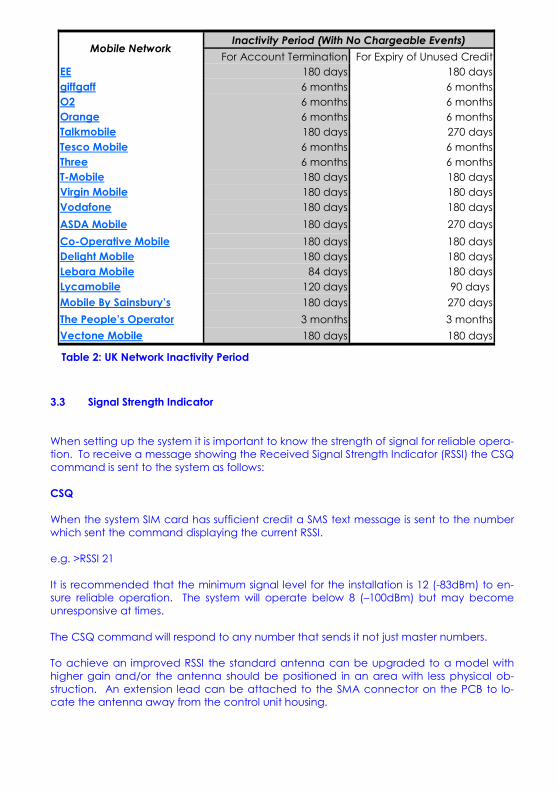
Mobile Network Inactivity Period (With No Chargeable Events)
For Account Termination For Expiry of Unused Credit EE 180 days 180 days
giffgaff 6 months 6 months O2 6 months 6 months Orange 6 months 6 months Talkmobile 180 days 270 days
Tesco Mobile 6 months 6 months Three 6 months 6 months T-Mobile 180 days 180 days Virgin Mobile 180 days 180 days
Vodafone 180 days 180 days
ASDA Mobile 180 days 270 days
Co-Operative Mobile 180 days 180 days Delight Mobile 180 days 180 days
Lebara Mobile 84 days 180 days
Lycamobile 120 days 90 days
Mobile By Sainsbury’s 180 days 270 days
The People’s Operator 3 months 3 months
Vectone Mobile 180 days 180 days
Table 2: UK Network Inactivity Period
3.4 Power Up/Reset Text Message
The system can send an message to all the text numbers when a system reset or power up has occurred. This can be due to network failure or power cycling (power off followed by power on). Note the system repeatedly resets during network out-age. You will only receive 1-message after a network outage. RSMS Enable enables the reset text message RSMS Disable disables the reset text message PSMS Enable enables the power up text message PSMS Disable disables the power up text message
3.5 SIM Card Balance Checking and Service Data Forwarding
The system is able to forward SMS messages and service sata which networks use to display remaining air-time minutes or credit. The forward function can also send network data used to register a SIM with the network website. All forwarded data is sent to the phone which set the service up. The forwarding service can be perma-nently enabled to forward all unsolicited messages from unrecognised numbers (i.e. not user or master numbers) to the forwarding phone number. However, to stop excessive ‘spamming’ and wasting credit, the service can be enabled in temporary mode limiting to forwarding messages for only 3 minutes after a master user has sent a valid message (typically the SMS or DIAL command). Additionally only one mes-sage will be forwarded every minute to ensure excessive numbers of messages are not sent. Forward Enable Forwarding service permanently enabled Forward Temp Forwarding for up to 3 mins after a valid messaged received Forward Disable No SMS/Service Data Message forwarding Networks require either a SMS text message to be sent to retrieve a balance or a network code to be dialled. Please check with your network to find your balance checking method. 3.6 Forwarding SMS Messages to any Number
Typically the SMS command is used to forward a SMS text to the network to request a balance. However the SMS function will forward the text to any number specified. SMS <number>,<text>.
Typical example (Orange, T-Mobile Balance Request) SMS 150,Balance sends ‘Balance’ to 150 This will text ‘Balance’ to number 150. Please note you need to ensure the forward service is set up as above to receive a reply from the system For network which require a code to be dialled use the DIAL for example Vectone UK: DIAL *102# dials ‘*102#’ for a balance request (see section 4.10 Dial Now)
3.7 Inverting the Relay Output
If desired the relay output can be inverted so that the Normally Open output termi-nal becomes the Normally Closed terminal and vice-verse. To invert the output the follow command is sent to the system: Normally Closed sets the Normally Open output to Normally Closed Normally Open sets the Normally Open output to Normally Open Whilst this is useful to change the operation remotely the system will draw an addi-tional 35mA at 12VDC. Also when the power is disconnected the relay will revert to it’s un-energised Normally Open state. 3.8 Input A Relay Control
Input A can be used to The activate the # relay as per a telephone call from a user. This is achieved by sending the Latch or Exit commands: Latch enable allows the relay to be activated by input A Exit enable allows the relay to be activated by input A Latch disable disables input A relay control Exit disable disables input A relay control
Notes
4 Relay Operation/Access Control
4.1 Enabling Any Number and Disabling Open-on-Call
The system can be setup to allow any number to operate the relay output. To enable any call the CALL command is used with the action ANY and is sent by the master phone in the following format: Call any
To return the system to operate from only valid user numbers the LIST action is sent with the CALL command as follows: call list
To disable activation of the relay by calling the following command is sent to the board (the relay can still be activated by SMS text; see OPEN/ON & CLOSE/OFF commands): CALL NONE
To switch the inputs on and off the CALL DIALER command is used. There is no relay acti-
vation by calling in this mode (although it can be activated by SMS text)
CALL DIALER switches the inputs on and off (see section 4)
When the inputs are being disabled the call is rejected; when the inputs are being en-abled the system rings out
4.2 Call Reject
By default any call to the system will be allowed to ring indefinitely (or up to the host net-work time limit). This is to avoid calls being diverted to voicemail when rejected by the system. However the system can be instructed to reject (hang up) calls using the REJECT command: REJECT ALL rejects all valid calls The reject command can also be used to determine the status of the relay when in tog-gle mode by sending the following command: REJECT OPEN rejects the call when the call is deactivating the relay connects the call when the call is activating the relay REJECT NONE disables all call rejection
4.3 Connecting a Call
By default, when called the system is set to ring indefinitely or until the SIM card network operator transfers the call to voicemail. However the system can be set to connect a call when the input is OPen (high/12V) or Closed (low/0V). This is done to allow the caller to know the state of the input even when the system has insufficient credit to send a status SMS text message. See also the REJECT command if call rejection is preferred.
To change the connect mode the CONN command is sent by the master phone with the action CL or OP. To disable connect on call the NOne action is sent. e.g. CONN CL connect when input high CONN OP connect when input low CONN NO do not connect call
4.4 Relay Activation Mode
When a valid call is received the relay can be set to activate for a set period of time (set by the RLYTIME command), to activate whilst the caller is ringing or to toggle between states on each call. By default the relay mode is set for timed (pulsed) activation. To switch to toggle mode the following message is sent to the system by the master number: RLYMODE TOG GLE enables toggle mode To activate the relay for however long the caller rings (n.b. turn off voicemail!) RLYMODE RING relay active whilst phone rings To revert to timed (pulsed) mode the following message is sent: RLYMODE PULSE relay Normally Open (NO) 4.5 Relay Activation Time
The RLYTIME command is used to adjust the time the relay is active following a call when RLYMODE is set to PULSE. By default the relay time is set to 3s. The time can be set from 1s to 999 seconds or 1 to 999 minutes using this command. To change the activation time the master number sends a SMS text message as follows: RLYTIME seconds.
e.g. rlytime 10. 1 second activation time rlytime 250s 250 second activation time Rlytime 1m. 1 minute activation time RLYTIME 960m. 16 hour (16 x 60mins) activation time 4.6 OPEN/ON & CLOSE/OFF Commands
The OPEN and ON commands are used to activate the relay with a SMS text message. The CLOSE and OFF commands deactivate the relay, whether activated by the OPEN or ON command or a call. When the OPEN command is sent without any additional instruc-tions the relay is activated indefinitely. When sent with a value and m(inutes) or s(econds) parameter the relay activates for a set period of time. The maximum number length is three characters therefore the timer is limited to 999 seconds or 999 minutes. If the m or s parameter is not sent then the timer value is read as the number of seconds. The ON and OFF commands are identical to the OPEN and CLOSE commands respec-tively and can be used interchangeably.
When sent with additional time information the relay is activated for however many sec-onds or minutes specified. e.g. OPEN activates relay indefinitely on activates relay indefinitely open 10. 10 second activation time (s parameter optional) Open 250s 250 second activation time ON 1m. 1 minute activation time open 960m. 16 hour (16 x 60mins) activation time CLOSE deactivates relay under all conditions OFF deactivates relay under all conditions
If the system loses power the relay state is restored when the power is reconnected!
4.7 Exit Switch Enable
The INPUTA connection can be used to activate the output relay which is ideal for con-nection to a secure-side exit switch. It uses the trigger level for the input text message (see INLVL) and activates the relay as per a phone call. To enable the exit switch input the EXIT command is sent to the board as follows: EXIT ENABLE enables the exit switch input Exit disable disable the exit switch input 4.8 Output Change Acknowledge SMS
Where necessary the board can send an acknowledgement SMS text message to all of the TEXTNUM numbers showing the current status of the output. When the output is actu-ated by a telephone call or text message the activating number is also sent. When the output is activated via an exit switch (see section 3.8) on INPUTA the relay status and ‘MANUAL’ message is sent. To activate and de-activate the acknowledge message the following command is sent to the board: Acknowledge Enable enables the acknowledge text ACKNOWLEDGE DISABLE disables the acknowledge text also valid,
ack e acknowledge enable ack d acknowledge disable
5 Auto-dialler: Input Triggered SMS Text Message Sending and Autodialing
The inputs can be used to trigger the sending of customisable SMS text messages to all of the ‘text numbers’ (see section 1.2 Number Types) and to sequentially dial all of the ‘call numbers’ (see section 1.2 Number Types). Call numbers are given priority and are dialled before the sending of SMS text messages to the Text Numbers. If no call numbers are stored no call dialling will occur and the sys-tem will begin sending SMS text messages straight away. Each input can be configured to either send a text message, initiate dialling or both send a text message and dial the call numbers. Each input can also be disabled by SMS re-motely. Each input has it’s own customisable message (see section 4.3) which can be sent when the associated input is triggered. Dialling can be triggered by any input. Additionally inputs A&B can initiate dialing in a logical OR configuration or can be triggered only when both inputs are active in a logical AND arrangement (see section 4.4). Additionally, dialling can be triggered only when input A is triggered followed by input B in an A THEN B sequence. Calls are dialled in the order in which they are added. The numbers are dialled sequen-tially until a call is answered and rejected (hung-up) or a call is answered and the ∗ key is pressed or until all of the numbers have been dialled. If a call is answered the system will automatically hang up the call after 5s. The board will then call the next number. During the 5s call the recipient can end dialling by holding the ∗ key on their phone or by hanging up on the call. After dialling is complete, the sys-tem will proceed to send the customisable text message to the list of text numbers. The maximum call length in auto-dialler mode is fixed at 5s. The maximum ring time (the time between dialling and call pick up) can be set using the RTIME command. The triggering of dialling and SMS messaging can be delayed using the HOLD command. If the input ceases to be active during the holding period the dialling and texting is can-celled. This is useful were the input is used to inform the user a door has been 5.1 Enabling and Disabling Inputs
To disable the dialer completely (all inputs) by calling the SIM card telephone number see section 4.1 (CALL DIALER command). To enable and disable autodialing and message sending on any input the following command is sent via a SMS text message by any mas-ter telephone number: INPUTA Auto enables autodialing on input A INPUTA Text enables SMS text sending on input A INPUTA Both enables both autodialing and SMS text sending on input A INPUTA Disable disables input A Similarly, INPUTB Auto enables autodialing on input B INPUTC Text enables SMS text sending on input C INPUTD Both enables both autodialing and SMS text sending on input D
also valid; inputa a enables autodialing on input B input t input A is the default input if not specified inpc b
INPD D
5.2 Input Change State Level
The INLEVEL commands sets the active state of the input for triggering the auto-dialler. For example, if the user requires triggering when the input is (going) closed (GND), then the following message is sent by the master number: INLEVEL CLOSED trigger when input A closed (GND/-VE) or, Inlevela negative trigger when input A closed (GND/-VE) If the trigger is required when the input goes open the following message is sent:
INLEVELB OPEN trigger when input B open (+VE) or, Inlevelc positive trigger when input C open (+VE) The input functions become inactive whilst the input remains in the active state (i.e. GND for INLEVEL CLOSED/+V for INLEVEL OPEN) and remains inactive for 5 seconds after return-ing to the idle state. INLEVEL BOTH allows triggering on either edge (no inactive state) INLEVELD BOTH trigger input D on either edge similarly;
INLEVELC C trigger when input C closed (GND) INLD O trigger when input D open (+VE) INL B trigger input A on either edge (BOTH) By default changes will only be made to input A if not specified by the INLEVEL com-mand. When connecting the input to a volt free relay output the default settings (INLEVEL CLOSED/NEGATIVE) are suitable for connection to NO/COM contacts. When connecting to NC/COM (for example when connecting to a typical PIR detector) the input level should be changed to: Inlevelx open This ensures the input triggers when the contact goes open-circuit. When connecting to a typical open-collector burglar alarm output (eg. Bell outputs/Strobe outputs/Set or unset outputs) then the default inlevel closed/negative settings should be used. On some alarm panels the bell output is positive 12v when actuating the alarm. In this case the inlevel positive/open command should be sent. A 1kohm resistor is typically connected over the input to ground in this case to stop the alarm off voltage ‘floating’.
5.3 Customising the Input Alert Message
The default input alert message is ‘>INPUTX ACTIVE’. This can be customised by the user using the CUSTOM command for each input. The maximum length of the message is 127 characters and it must end with a full stop. The custom command is used as follows: CUSTOMA THE GATE IS OPEN. customised A message CUSTOMB THE PUMP HAS STOPPED PLEASE CALL 07000000000. customised B message Custom1 the voltage is outside the specified limits. analogue input 1 message Use only text or number characters in the message. The message will end where there is a full stop. Do not use a full stop in the middle of the message. If you do not specify the channel the message is applied to channel A. Separate messages can be specified for when the channel is triggered by a positive going (logic HIGH) edge or a negative going edge (LOW). This is achieved by adding the appro-priate suffix to the command (this is particularly useful when INLEVEL is set to BOTH: CUSTOMAH this is sent when input A goes positive. CUSTOMBL this is sent when input B goes negative. When setting analogue channel customised messages the over-voltage message is set using the H (high) suffix. Similarly when setting the under voltage limit the L (low) suffix is used. Custom2H this is the an2 channel over-voltage message custom2L this is the an2 channel under-voltage message 5.4 Autodial Logic
By default, if both inputs are set to autodial, then if either input is triggered dialling will com-mence (OR configuration). If desired the system can be set to require both inputs to be in the active state in order to initiate dialling (AND configuration). Additionally the system can be set for input A to be triggered before input B (A THEN B) in order to initiate dialling. To change the autodial logic settings the following message is sent to the board: autodial AND requires both inputs to be active to initiate dialling autodial OR triggering either input initiates dialling AUTODIAL THEN A THEN B triggering
aut A
aut o
Aut T
5.5 Changing the Maximum Ring Time
The maximum time for which the system will attempt dialling before dialling the next num-ber is set using the RTIME command. The default time limit is 60s. The RTIME command is specified in seconds and can be set from 1s to 255s. Most calls will require at least 15s for connection which is included in RTIME.
RTIME 45. sets the maximum ring time to 45 seconds
5.6 Changing the Maximum Call Time
The maximum time limit for an answered call is set using the CTIME command. The de-fault time limit is 45s. The CTIME command is specified in seconds and can be set from 1s to 255s. CTIME 45. sets the maximum call time to 45 seconds
5.7 Changing the Maximum Line Silence Time
The maximum time for which a silent call will remain connected is set using the SILENCE command. This is useful were a call may be redirected to voicemail. The silence during recording will cause the system to hang the call. The default silence time is 15s and can be set from 1s to 255s. STIME 25. sets the maximum line silence time to 25 seconds
5.8 Adding Auto-dialler SMS Text Numbers
The system can send the input triggered message (2.16) to up to all 511 numbers. To add a text number the following SMS text message is sent to the system by any master num-ber:
TEXTNUM<space>number.
e.g. textnum 07000000000.
5.9 Adding Auto-dialler Call Numbers
The system can call up to all 511 numbers when the input is triggered. To add a call num-ber the following SMS text message is sent to the system by any master number:
CALLNUM<space>number. e.g. callnum 07000000000.
5.10 Assigning a Number to Specified Channel Only
Both Call and Text Numbers can be assigned to call/text only when one particular chan-nel is activated. This is done by appending A or B to the CALLNUM and TEXTNUM com-mands as follows: CALLNUMA 07000000000 calls the number 07000000000 only when channel A is active
TEXTNUMB 07000000000 texts the number 07000000000 only when channel B is active N.B. Text/Call numbers can also activate the output—there is no need to ADD the number
It is important to know that channels A&C and analogue input 1 are common. Numbers
specified for channel A will also be sent message/dialled when input C and analogue input 1 are triggered. Similarly input B shares its number with D and analogue input 2.
5.11 International Calling/Texting
The system can call/text international numbers, however the exit code should not be specified and should be replaced with the ‘+’ symbol e.g: UK Number 07574163367 should be entered as +447574163367 when outside the UK
5.12 Dial Now
If necessary the system can make a call to a number not stored in it’s memory at any time. This is achieved using the DIAL command. The call observes the RTIME, CTIME and SILENCE time settings DIAL<space>number. make an ad-hoc call to the specified number e.g. dial 01517283167. The call will end when the other party hangs up or the CTIME or SILENCE time limit is reached. 5.13 Input Hold-off Time
Dialling and SMS sending can be delayed from 1 second to up to 500 minutes (over 8 hours) on any input using the HOLD command. Additionally after sending the SMS mes-sage/dialling the call numbers the system can repeat the action after the delay time again if required. To set up the hold-ff time the following SMS text is sent to the system; HOLD 10 10s delay on Input A HOLDA R10 10s delay on Input A; repeat every 10s HOLDB R120m. 120 minute delay on Input B; repeat every 120 mins (2 hours) Holdc 2s 2 second delay on Input C hold1 0 turn off delay on analogue input 1 (set delay time to zero) NB. If the input is not specified then the default input is Input A 5.14 Repeating the SMS/Call
Dialling and SMS sending can be repeated after a user specified period from 1 second to up to 500 minutes (over 8 hours) on any input using the REPEAT command. The call is made/SMS sent immediately on the input becoming active and is repeated after the time specified. repeatA 10m. resends input A SMS/restarts dialling after 10 minutes Repeat1 120. resends analogue channel 1 SMS/restarts dialling after 120s 5.15 Silencing the Alarm
The bell –ve wire can be routed through the relay COM and NC terminals onto the bell. This allows the relay to break the connection when active and silence the alarm. Whilst the bell is sounding the SILENCE command can be used to silence the bell. The connec-tion is re-established once both inputs return to the idle state (i.e. the alarm panel is reset) silence activates the output relay until the inputs are idle
6. Analogue Voltage Measurements
Analogue inputs 1 & 2 are able to measure voltages between 0V and 36V (accuracy 0.5v or better) When a voltage on the input exceeds the upper voltage limit the high SMS messages are sent to the text numbers and dialling commences. Similarly when a voltage drops below the lower voltage limit dialling commences and the low voltage message is sent to the text numbers associated with that input. Input 1 sends SMS messages to channel A numbers or both if not specified. Input 2 sends messages to channel B numbers or both if not specified. The low voltage message is customised using the CUSTOMXL command (where X is the channel number) and the over voltage message is specified using the CUS-TOMXH command. Analogue inputs can be connected directly to burglar alarm zone terminals. This allows an individual zone to be monitored even when the alarm is not armed. To determine the required voltage levels the STATUS message is sent in both active and in-active states. This reports the voltage of both states so the limits can be set. The supply voltage is measured and an under and over voltage message is sent to the master numbers should the supply voltage drop or exceed the maximum permis-sible voltage. The supply voltage is monitored after the bridge rectifier DC output (see diagram below). There is therefore a voltage drop of ~0.7V per voltage input A&B (i.e. VINA and VINB). When connecting a DC voltage to VINA and GND there will be a 0.7V drop. When connecting DC to VINA and VINB there will be a 1.4V drop. As the AC voltage is rectified, the voltage measured will be the peak voltage not RMS voltage found by multiplying the RMS by √2. Therefore a 24VAC supply will be measured as ~32V 24 x √2—0.7—0.7 ~32VDC 6.1 Setting the Upper Voltage Threshold Voltage
The VUPPERX command is used to set the upper voltage threshold. When the input voltage rises above this voltage the upper voltage message is sent. The range can be set between 0V and 36V. Setting the upper voltage to 36.0V will ensure no upper voltage messages are sent; the measured voltage must exceed the limit (not be equal to the limit). VUPPER2 35.1 initiates dialling and SMS sending when AN2 exceeds 35.1V VUPPER1 28 initiates dialling and SMS sending when AN1 exceeds 28.0V VUPPER1 36.0 no measured voltage can exceed 36.0V hence no alerts 6.2 Setting the Lower Voltage Threshold Voltage
The VLOWERX command is used to set the lower voltage threshold. When the input voltage drops below this voltage the lower voltage message is sent. Setting the lower voltage to 0V will ensure no lower voltage messages are sent; the measured voltage must be below the limit (not be equal to the limit). vlower2 10.0 initiates dialling and SMS sending when AN2 is below 10.0V vlower1 0 no measured voltage can be below 0V hence no alerts
7 GPRS PC Connection
The system can connect to a PC running Advent Controls Remote Setup software. The most common method for accessing the system remotely using a PC is shown below 7.1 Specifying the Access Point Name (APN)
It is essential that your GSM network’s Access Point Name (APN) is specified. This informa-tion can typically be found from your network’s website. Some common networks are de-tailed below. To set up the APN the APN command is used as follows APN “access point name”,”username”,”password”. Examples: Vectone Mobile
APN: uk.mundio.com User: vectone PWD: none
Command to be sent to the system:
APN “uk.mundio.com”,”vectone”.
GiffGaff
APN: giffgaff.com User: giffgaff PWD: none
Command to be sent to the system:
APN “giffgaff.com”,”giffgaff”.
7.2 Initiating a Connection
To initiate a connection with your PC running the Advent Controls Remote Setup Software the IP Address of your PC is required. This can be found by searching for ’my IP address’ in a search engine. You should also set your router port forwarding for port 88 to direct con-nections to your PC. To initiate a connection the IP command is used as follows: IP “<IPV4 address>”,”<port>“ IP “97.77.43.250” using default port of 88 The unit may become unresponsive for up to 3 minutes after a connection.
8 Installation
8.1 Power Connection
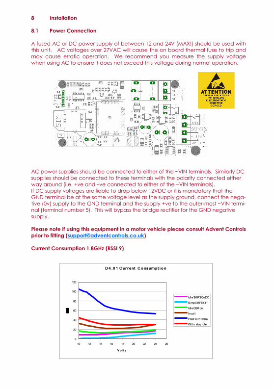
A fused AC or DC power supply of between 12 and 24V (MAX!) should be used with this unit. AC voltages over 27VAC will cause the on board thermal fuse to trip and may cause erratic operation. We recommend you measure the supply voltage when using AC to ensure it does not exceed this voltage during normal operation. AC power supplies should be connected to either of the ~VIN terminals. Similarly DC supplies should be connected to these terminals with the polarity connected either way around (i.e. +ve and –ve connected to either of the ~VIN terminals). If DC supply voltages are liable to drop below 12VDC or it is mandatory that the GND terminal be at the same voltage level as the supply ground, connect the nega-tive (0v) supply to the GND terminal and the supply +ve to the outer-most ~VIN termi-nal (terminal number 5). This will bypass the bridge rectifier for the GND negative supply. Please note if using this equipment in a motor vehicle please consult Advent Controls
prior to fitting ([email protected])
Current Consumption 1.8GHz (RSSI 9)
D4 .0 1 Current Consumpt ion
0
20
40
60
80
100
120
10 12 14 16 18 20 22 24 26
V ol t s
Idle SMPS On DC
Sleep SMPS Of f
Idle GSM on
In cal l
Peak wi th Relay
Wi th r elay Idle
8.2 Input Connection
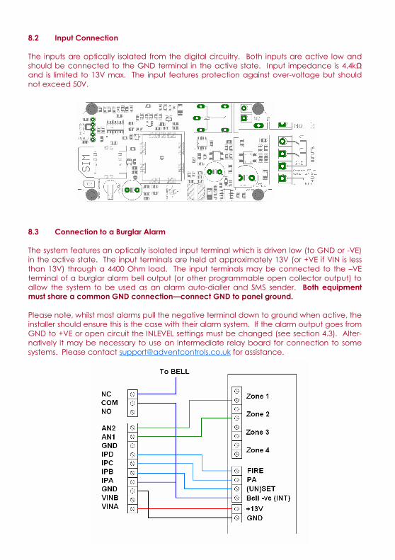
The inputs are optically isolated from the digital circuitry. Both inputs are active low and should be connected to the GND terminal in the active state. Input impedance is 4.4kΩ and is limited to 13V max. The input features protection against over-voltage but should not exceed 50V. 8.3 Connection to a Burglar Alarm
The system features an optically isolated input terminal which is driven low (to GND or -VE) in the active state. The input terminals are held at approximately 13V (or +VE if VIN is less than 13V) through a 4400 Ohm load. The input terminals may be connected to the –VE terminal of a burglar alarm bell output (or other programmable open collector output) to allow the system to be used as an alarm auto-dialler and SMS sender. Both equipment must share a common GND connection—connect GND to panel ground. Please note, whilst most alarms pull the negative terminal down to ground when active, the installer should ensure this is the case with their alarm system. If the alarm output goes from GND to +VE or open circuit the INLEVEL settings must be changed (see section 4.3). Alter-natively it may be necessary to use an intermediate relay board for connection to some systems. Please contact [email protected] for assistance.
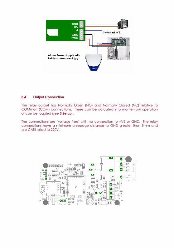
8.4 Output Connection
The relay output has Normally Open (NO) and Normally Closed (NC) relative to COMmon (COM) connections. These can be actuated in a momentary operation or can be toggled (see 3 Setup). The connections are ‘voltage free’ with no connection to +VE or GND. The relay connections have a minimum creepage distance to GND greater than 5mm and are CATII rated to 220V.
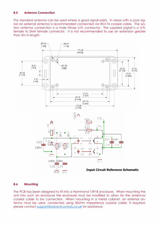
8.5 Antenna Connection
The standard antenna can be used where a good signal exists. In areas with a poor sig-nal an external antenna is recommended connected via RG174 coaxial cable. The sys-tem antenna connection is a male Hirose U.FL connector. The supplied pigtail is a U.FL female to SMA female connector. It is not recommended to use an extension greater than 3m in length.
8.6 Mounting
The PCB has been designed to fit into a Hammond 1591B enclosure. When mounting the unit into such an enclosure the enclosure must be modified to allow for the antenna/coaxial cable to be connected. When mounting in a metal cabinet, an external an-tenna must be used, connected using 50ohm impedance coaxial cable. If required, please contact [email protected] for assistance.
Input Circuit Reference Schematic
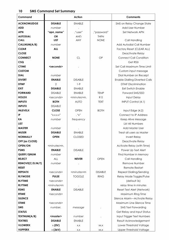
10 SMS Command Set Summary
Command Action Comments
ACKNOWLEDGE DISABLE ENABLE SMS on Relay Change State
ADD number . Add User Number
APN “apn_name” ,“user” ,”password” Set Network APN
AUTODIAL OR AND THEN CALL LIST ANY NONE Call Handling
CALLNUM(A/B) number Add Autodial Call Number
CLEAR ALL Factory Reset (CLEAR ALL)
CLOSE Deactivate Relay
CONNECT NONE CL OP Connect Call Condition
CSQ Get RSSI
CTIME <seconds> . Set Call Maximum Time Limit
CUSTOM Custom input message
DIAL number Dial Number on Receipt
DIVERT ENABLE DISABLE Enable Dialling Diverted Calls
EXIT DISABLE ENABLE Exit Switch Enable
FORWARD DISABLE ENABLE TEMP Forward SMS/SSD
HOLDX <seconds> <minutes>m. R 0 Input Delay
INPUTX BOTH AUTO TEXT INPUT Control (4.1)
INPUTX DISABLE
INLEVELX CLOSE OPEN BOTH Input Edge (4.2)
IP “x.x.x.x” ,“x” Connect to IP Address
KA number frequency Keep Alive Message
LIST List All Numbers
MASTER number . Add Master User
MUSER DISABLE ENABLE Treat all users as Master
OFF [as CLOSE Deactivate Relay
OPEN/ON <minutes>m. Activate Relay (with Time)
PSMS ENABLE DISABLE Power Up Text Alert
QUERY/QNUM number . Find Number in Memory
REJECT ALL NEVER OPEN Call Handling
REMOVE(C/D/M/T) number . Remove Number
RESET Remote Restart
REPEATX <seconds> <minutes>m DISABLE Repeat Dialling/Sending
RLYMODE PULSE TOGGLE RING Relay Mode Toggle/Pulse
RLYTIME <seconds> (default 3s)
RLYTIME <minutes>m . relay time in minutes
RSMS ENABLE DISABLE Reset Text Alert (Network)
RTIME <seconds> Maximum Ring Time
SILENCE Silence Alarm—Activate Relay
STIME <seconds> Maximum Line Silence Time
SMS number, message . SMS Text Forwarding
STATUS Get Relay and Input Status
TEXTNUM(A/B) <master> number . Input Trigger Text Numbers
TEXTRES DISABLE ENABLE Result Acknowledgement
VLOWERX x (0V) x.x xx.x Lower Threshold Voltage
VUPPERX x (36V) x.x xx.x Upper Threshold Voltage
NORMALLY OPEN CLOSED Invert Relay
DTMF 2 1-9 DTMF Discrimination