Embed Size (px)
Citation preview
QUICK START
Copyright © 2000 ROLAND CORPORATIONAll rights reserved. No part of this publication may be reproduced in any form without the written permissionof ROLAND CORPORATION.
Thank you for purchasing the Roland XV-5080 synthesizer module.
Before using this unit, carefully read the sections entitled: “IMPORTANT SAFETY INSTRUCTIONS”(Owner’s manual p. 2), “USING THE UNIT SAFELY” (Owner’s manual p. 3, 4), and “IMPORTANTNOTES” (Owner’s manual p. 5). These sections provide important information concerning the properoperation of the unit. Additionally, in order to feel assured that you have gained a good grasp of ev-ery feature provided by your new unit, Owner’s Manual and Quick Start should be read in its entire-ty. The manual should be saved and kept on hand as a convenient reference.
The guide comprises three sections, a “Quick Start” manual, an“Owner’s Manual”and a “Q&A, Sound List.”
The “Quick Start” manual (this volume) explains the XV-5080’s basic functions using examples that are clear and easy to grasp. Read this volume first.
In addition to the XV-5080’s basic operations, the “Owner’s Manual” provides descriptions of more advanced uses and applications. When referring to the Owner’s Manual, you can find the information you are looking for by checking the Table of Contents, and Index in each page.
The “Q&A, Sound List” contains frequently asked questions about the XV-5080, along with answer to those questions.
* The display screens printed in this owner's manual are based on the factory settings. However, please be aware that in some cases they may differ from the actual factory settings.
2
Contents
Getting Read
Installing the PrecauInstalli
Installation dConnecting toTurning the PRestoring the
Listening to t
Try Out the S
Playing PatchSelecting Patc
SelectinSelectinMaking
Switching MoSelecting SouPlaying Soun
ConnecSetting
Playing MultiSelectinTurninAssignChangi
Having DifferSelectinSetting
Try Using an Using aUsing a
Turning Effec
Let’s Play So
Installing the CautionRemovConfirm
Augmenter laEnleveAssure
Connecting thLoading SamPlaying Back
Let’s Make a
Registering a Selecting Patc
Using the XV-
Using the XVUsing an Exte
For More Adv
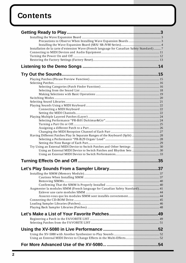
y to Play.............................................................................3Wave Expansion Board ..................................................................................................... 3tions to Observe When Installing Wave Expansion Boards ......................................... 3ng the Wave Expansion Board (SRX/SR-JV80 Series)................................................... 4e la carte d'extension Wave (French language for Canadian Safety Standard) ......... 7 MIDI Devices and Audio Equipment.......................................................................... 11ower On and Off .............................................................................................................. 12 Factory Settings (Factory Reset)..................................................................................... 13
he Demo Songs ..............................................................14
ounds...............................................................................15es (Phrase Preview Function) ......................................................................................... 15hes....................................................................................................................................... 16g Categories (Patch Finder Function) ........................................................................... 16g from the Sound List ..................................................................................................... 18 Selections with Basic Operations ................................................................................. 19des ...................................................................................................................................... 20
nd Libraries........................................................................................................................ 21ds Using a MIDI Keyboard.............................................................................................. 22ting a MIDI Keyboard ..................................................................................................... 22
the MIDI Channels........................................................................................................... 22ple Layered Patches (Layer) ........................................................................................... 24g Performance “PR-B:01 Dulcimar&Gtr”..................................................................... 24
g a Part On or Off.............................................................................................................. 25ing a different Patch to a Part.......................................................................................... 26ng the MIDI Reception Channel of Each Part .............................................................. 27ent Patches Play In Separate Ranges of the Keyboard (Split) ................................... 28g a Performance “PR-B:29 Organ/Lead”..................................................................... 28
the Note Range of Each Part........................................................................................... 29External MIDI Device to Switch Patches and Other Settings .................................... 30n External MIDI Device to Switch Patches and Rhythm Sets ................................... 30n External MIDI Device to Switch Performances........................................................ 33
ts On and Off ..................................................................35
unds From a Sampler Library........................................37SIMM (Memory Module) ................................................................................................ 37s When Installing SIMM ................................................................................................ 37
ing SIMMs.......................................................................................................................... 40ing That the SIMM Is Properly Installed .................................................................... 40
modules SIMM (French language for Canadian Safety Standard).......................... 41r une carte modules SIMM .............................................................................................. 44z-vous que les modules SIMM sont installés correctement........................................ 44e CD-ROM Drive ............................................................................................................. 45
pler Libraries (Patches)..................................................................................................... 46Sampler Libraries (Patches) ............................................................................................ 48
List of Your Favorite Patches........................................49Patch in the FAVORITE LIST ......................................................................................... 49hes from the FAVORITE LIST........................................................................................ 51
5080 in Live Performance .............................................52-5080 with Another Synthesizer to Play Sounds .......................................................... 52rnal MIDI Device to Change Effects in the Multi-Effects........................................... 52
anced Use of the XV-5080... ..........................................54
Getting Ready to Play
Installing the Wave Expansion BoardThe XV-5080 can be further expanded with the installation of up to eight optional wave expansion boards (up to four SRX Series boards and four SR-JV80 Series boards). Wave data is stored in these wave expansion boards. Also stored are Patches and Rhythm Sets that use the Wave data from the wave expansion boards, allowing these to be called up directly for use.
Precautions to Observe When Installing Wave Expansion Boards
• To avoid the risk of damage to internal components that can be caused by static electricity, please carefully observe the following whenever you handle the board.
❍ Before you touch the board, always first grasp a metal object (such as a water pipe), so you are sure that any static electricity you might have been carrying has been discharged.
❍ When handling the board, grasp it only by its edges. Avoid touching any of the electronic components or connectors.
❍ Save the bag in which the board was originally shipped, and put the board back into it whenever you need to store or transport it.
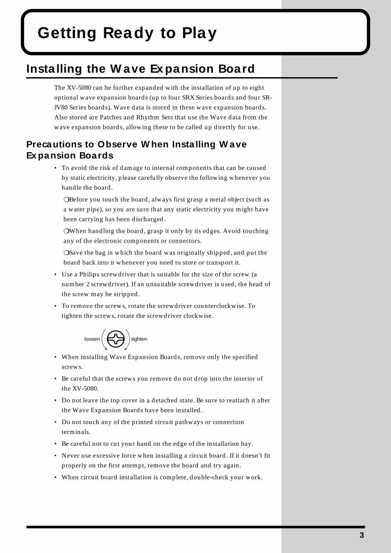
• Use a Philips screwdriver that is suitable for the size of the screw (a number 2 screwdriver). If an unsuitable screwdriver is used, the head of the screw may be stripped.
• To remove the screws, rotate the screwdriver counterclockwise. To tighten the screws, rotate the screwdriver clockwise.
fig.00-001.e(screws)
• When installing Wave Expansion Boards, remove only the specified screws.
• Be careful that the screws you remove do not drop into the interior of the XV-5080.
• Do not leave the top cover in a detached state. Be sure to reattach it after the Wave Expansion Boards have been installed.
• Do not touch any of the printed circuit pathways or connection terminals.
• Be careful not to cut your hand on the edge of the installation bay.
• Never use excessive force when installing a circuit board. If it doesn’t fit properly on the first attempt, remove the board and try again.
• When circuit board installation is complete, double-check your work.
tightenloosen
3
Getting Ready to Play
Wave expansion boards (SR-JV80 Series and SRX Series; sold separately) are installed after removing the cover at the top of the unit. Insert SRX Series boards in the EXP-E through -H slots, and SR-JV80 Series boards in the EXP-A through -D slots.
Installing the Wave Expansion Board (SRX/SR-JV80 Series)
1 Before installing any Wave Expansion Board, turn off the power on the XV-5080 and all devices connected to it.
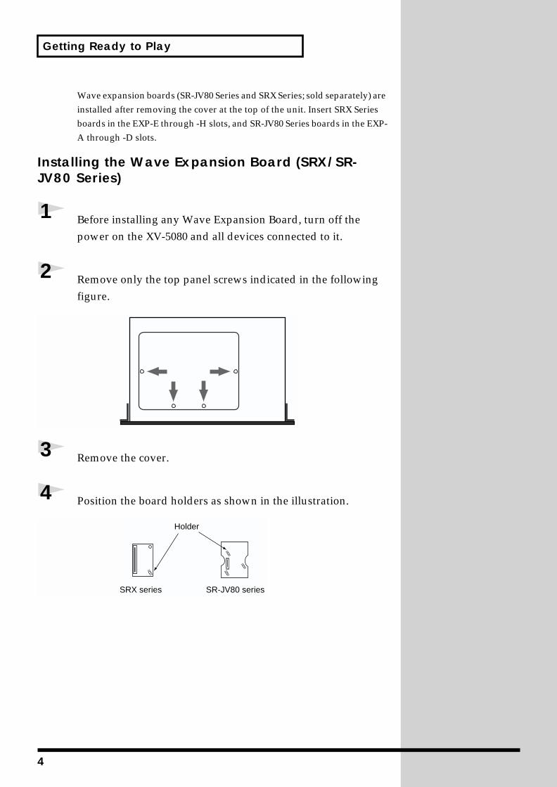
2 Remove only the top panel screws indicated in the following figure.
fig.00-002.e(top panel)
3 Remove the cover.
4 Position the board holders as shown in the illustration.fig.00-003.e(exp-board holder)
Holder
SRX series SR-JV80 series
4
Getting Ready to Play
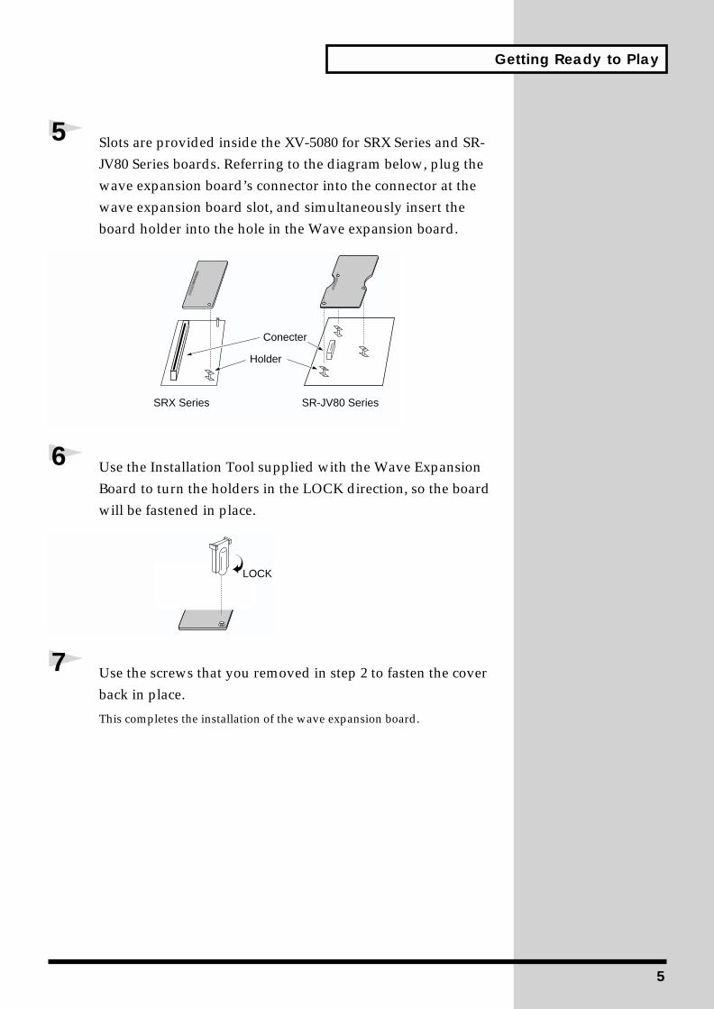
5 Slots are provided inside the XV-5080 for SRX Series and SR-JV80 Series boards. Referring to the diagram below, plug the wave expansion board’s connector into the connector at the wave expansion board slot, and simultaneously insert the board holder into the hole in the Wave expansion board.
fig.00-004.e(Install)
6 Use the Installation Tool supplied with the Wave Expansion Board to turn the holders in the LOCK direction, so the board will be fastened in place.
fig.00-005.e(lock)
7 Use the screws that you removed in step 2 to fasten the cover back in place.
This completes the installation of the wave expansion board.
Holder
Conecter
SRX Series SR-JV80 Series
LOCK
5
Getting Ready to Play
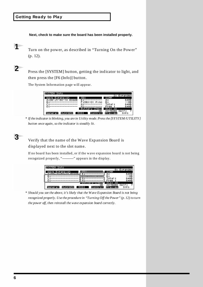
Next, check to make sure the board has been installed properly.
1 Turn on the power, as described in “Turning On the Power” (p. 12).
2 Press the [SYSTEM] button, getting the indicator to light, and then press the [F6 (Info)] button.
The System Information page will appear.fig.00-007.e_80
* If the indicator is blinking, you are in Utility mode. Press the [SYSTEM/UTILITY]
button once again, so the indicator is steadily lit.
3 Verify that the name of the Wave Expansion Board is displayed next to the slot name.
If no board has been installed, or if the wave expansion board is not being recognized properly, “----------” appears in the display.
fig.00-008.e
* Should you see the above, it’s likely that the Wave Expansion Board is not being
recognized properly. Use the procedure in “Turning Off the Power” (p. 12) to turn
the power off, then reinstall the wave expansion board correctly.
6
Getting Ready to Play
Installation de la carte d'extension Wave(French language for Canadian Safety Standard)
Les cartes d'exten-sion Wave contiennent des donnees Wave, aussi bien que des morceaux musicaux et des ensembles rythmiques utilisant ces donnees, auxquelles on peut directement acceder dans la zone temporaire et les faire jouer.
Precautions lors de l'installation de la carte d'extension Wave● Pour éviter tout dommage des composants internes pouvant provenir de
l’électricité statique, veuillez suivre les conseils suivants quand vous installez la carte.• Avant de toucher la carte, saisissez toujours un objet métallique
(tuyau d’eau ou autre) pour être sûr que l’électricité statique se décharge.
• Quand vous saisissez la carte, prenez-la par les bords. Evitez de toucher les composants électroniques ou les connecteurs.
• Conservez le sac dans lequel la carte était emballée et remettez la carte dedans pour l’expédier ou l’entreposer.
● Utiliser un tournevis cruciforme correspondant à la taille de la vis (un tournevis numéro 2). En cas d’utilisation d’un tournevis inapproprié, la tête de la vis pourrait être endommagée.
● Pour enlever les vis, tourner le tournevis dans le sens contraire des aiguilles d’une montre. Pour resserrer, tourner dans le sens des aiguilles d’une montre.
● Lors de l’insertion de la carte d’extension Wave, enlevez seulement les vis indiquées dans les instructions.
● Veillez à ne pas laisser tomber de vis dans le châssis du XV-5080.● Ne pas laisser le panneau de protection avant détaché. S’assurer de
l’avoir rattacher après avoir installé le disque dur.● Ne touchez aucun des circuits imprimés ni les bornes de connexion.● Veillez à ne pas vous couper les doitgs sur le bord de l’ouverture
d’installation.● Ne jamais forcer quand vous installez une carte de circuits. Si la carte ne
rentre pas correctement, ressortez-la et ressayez.● Quand la carte est installée, vérifiez si l’installation est correcte.
resserrerdesserrer
7
Getting Ready to Play
Pour installer une carte d'extension (vendue en option dans les séries SR-JV80 et SRX), détacher la plaque du dessus. La carte de série SRX s'installe dans l'emplacement EXP-E–H et la carte de série SR-JV80, dans l'emplacement EXP-A–D.
1 Avant d'installer la carte d'extension, éteindre le XV-5080 et tous les appareils qui y sont reliés.
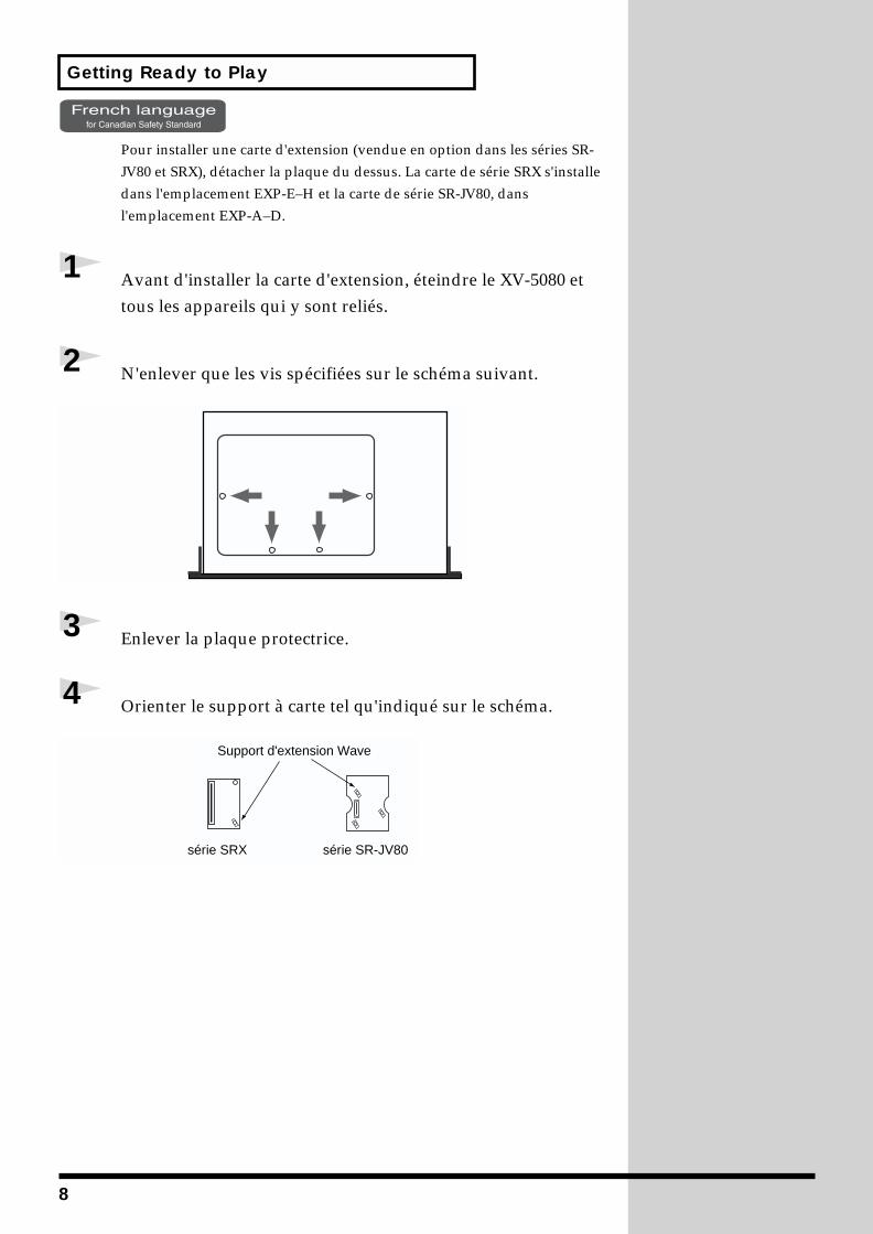
2 N'enlever que les vis spécifiées sur le schéma suivant.
3 Enlever la plaque protectrice.
4 Orienter le support à carte tel qu'indiqué sur le schéma.
Support d'extension Wave
série SRX série SR-JV80
8
Getting Ready to Play
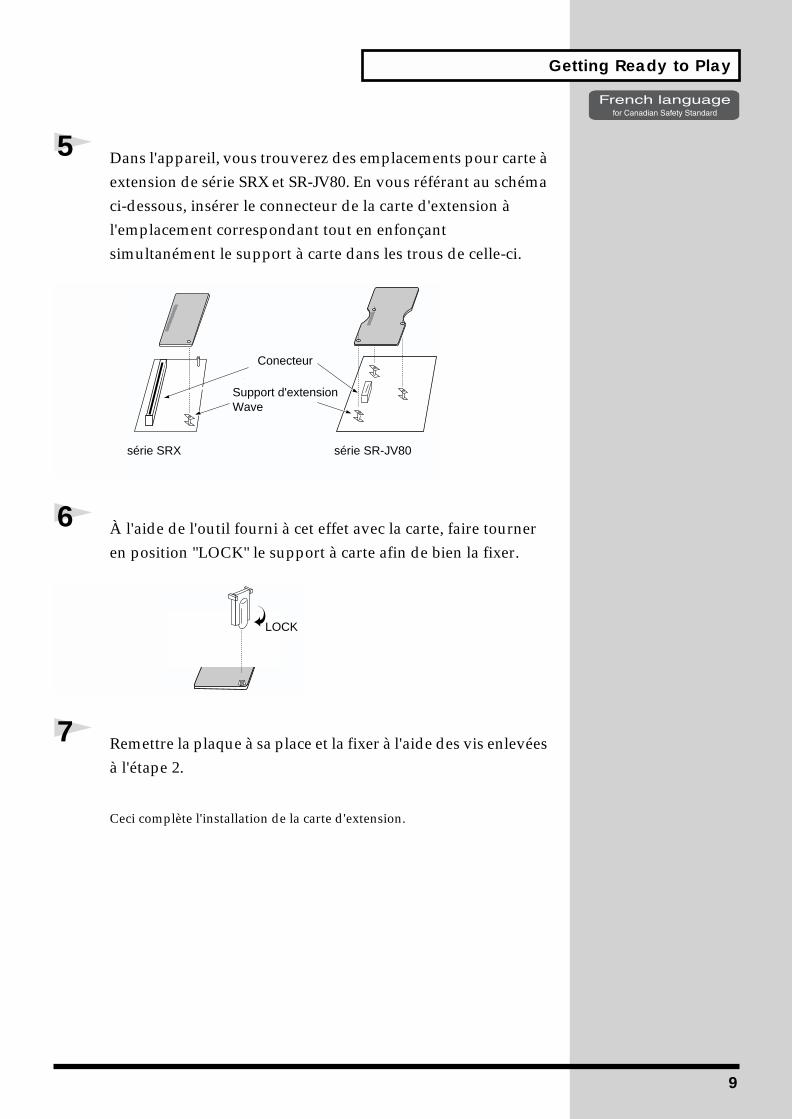
5 Dans l'appareil, vous trouverez des emplacements pour carte à extension de série SRX et SR-JV80. En vous référant au schéma ci-dessous, insérer le connecteur de la carte d'extension à l'emplacement correspondant tout en enfonçant simultanément le support à carte dans les trous de celle-ci.
6 À l'aide de l'outil fourni à cet effet avec la carte, faire tourner en position "LOCK" le support à carte afin de bien la fixer.
7 Remettre la plaque à sa place et la fixer à l'aide des vis enlevées à l'étape 2.
Ceci complète l'installation de la carte d'extension.
Conecteur
série SRX série SR-JV80
Support d'extension Wave
LOCK
9
Getting Ready to Play
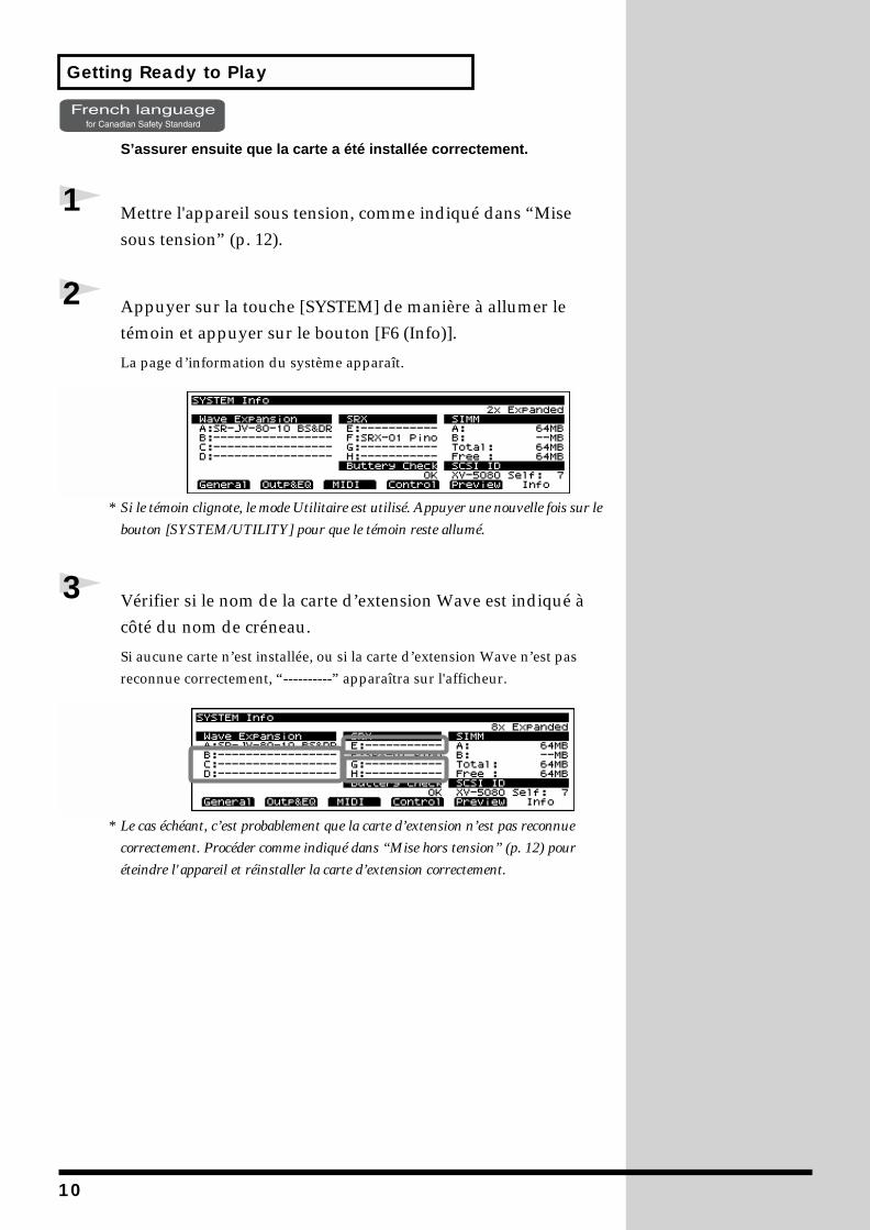
S’assurer ensuite que la carte a été installée correctement.
1 Mettre l'appareil sous tension, comme indiqué dans “Mise sous tension” (p. 12).
2 Appuyer sur la touche [SYSTEM] de manière à allumer le témoin et appuyer sur le bouton [F6 (Info)].
La page d’information du système apparaît.fig.00-007.e_80
* Si le témoin clignote, le mode Utilitaire est utilisé. Appuyer une nouvelle fois sur le
bouton [SYSTEM/UTILITY] pour que le témoin reste allumé.
3 Vérifier si le nom de la carte d’extension Wave est indiqué à côté du nom de créneau.
Si aucune carte n’est installée, ou si la carte d’extension Wave n’est pas reconnue correctement, “----------” apparaîtra sur l'afficheur.
fig.00-008.e
* Le cas échéant, c’est probablement que la carte d’extension n’est pas reconnue
correctement. Procéder comme indiqué dans “Mise hors tension” (p. 12) pour
éteindre l'appareil et réinstaller la carte d’extension correctement.
10
Getting Ready to Play
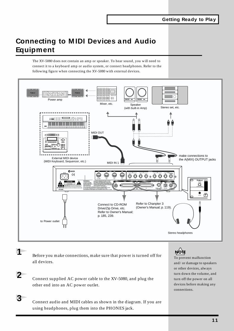
Connecting to MIDI Devices and Audio Equipment
The XV-5080 does not contain an amp or speaker. To hear sound, you will need to connect it to a keyboard amp or audio system, or connect headphones. Refer to the following figure when connecting the XV-5080 with external devices.
fig.00-009.e(connections)_98
1 Before you make connections, make sure that power is turned off for all devices.
2 Connect supplied AC power cable to the XV-5080, and plug the other end into an AC power outlet.
3 Connect audio and MIDI cables as shown in the diagram. If you are using headphones, plug them into the PHONES jack.
Power amp
MIDI IN 1
MIDI OUT
External MIDI device(MIDI Keyboard, Sequencer, etc.)
Mixer, etc. Speaker(with built-in Amp) Stereo set, etc.
Stereo headphones
to Power outlet
make connections tothe A(MIX) OUTPUT jacks
Refer to Chanpter 3(Owner's Manual; p. 119).
Connect to CD-ROMDrive/Zip Drive, etc.Refer to Owner's Manual; p. 185, 239.
To prevent malfunction and/or damage to speakers or other devices, always turn down the volume, and turn off the power on all devices before making any connections.
11

Getting Ready to Play
Turning the Power On and Off
Turning On the PowerOnce the connections have been completed (p. 11), turn on power to your various devices in the order specified. By turning on devices in the wrong order, you risk causing malfunction and/or damage to speakers and other devices.
1 Before you turn the power on, check to make sure that:
• Are all devices connected properly?
• Are the volume levels on the XV-5080 and any amp or mixer that is connected turned down to the lowest settings?
2 Turn on the power to connected SCSI devices.
3 Press the XV-5080’s [POWER] switch to turn on the power.fig.00-010.e(power button)
4 Turn on the power to connected audio devices.
Turning Off the Power
1 Before turning off the power, confirm the following.
• Are the volume levels on the XV-5080 and any amp or mixer that is connected turned down to the lowest settings?
• Have you saved your data, including data for any sounds you have created? (Owner’s Manual; p. 194)
2 Turn off the power to connected external devices.
3 Press the XV-5080’s [POWER] switch to turn off the power.
This unit is equipped with a protection circuit. A brief interval (a few seconds) after power up is required before the unit will operate normally.
12
Getting Ready to Play
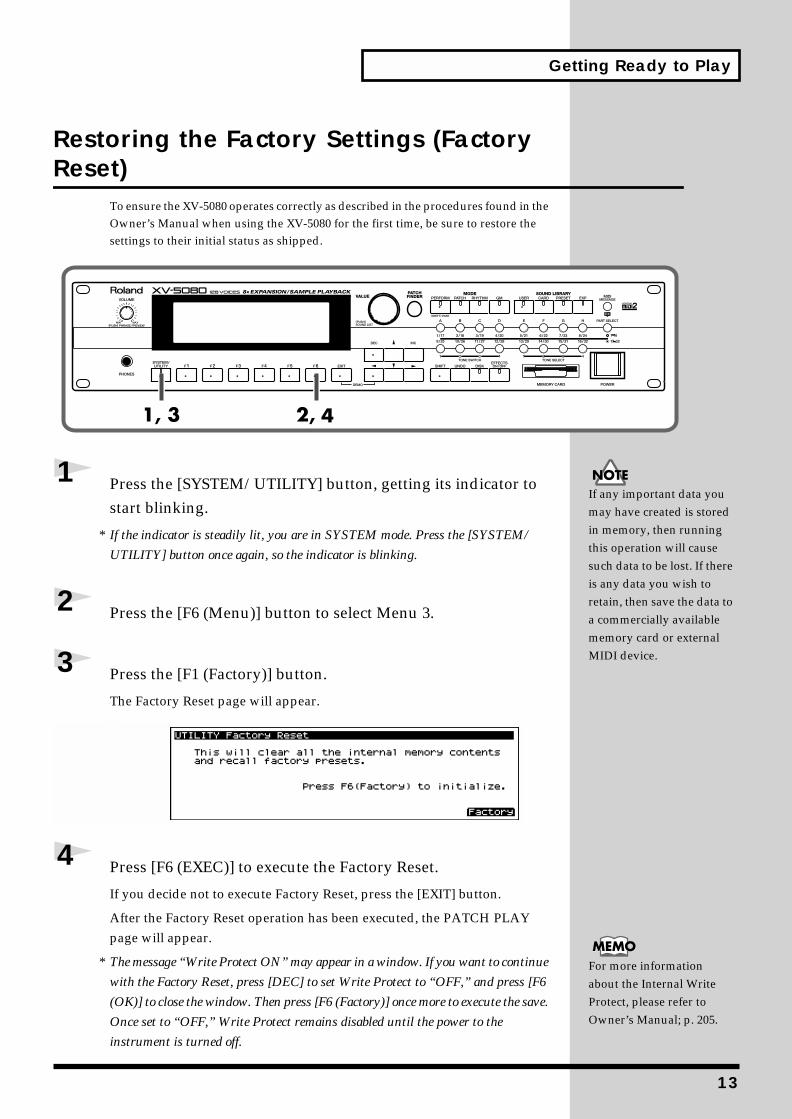
Restoring the Factory Settings (Factory Reset)
To ensure the XV-5080 operates correctly as described in the procedures found in the Owner’s Manual when using the XV-5080 for the first time, be sure to restore the settings to their initial status as shipped.
fig.00-011.e_80
1 Press the [SYSTEM/UTILITY] button, getting its indicator to start blinking.
* If the indicator is steadily lit, you are in SYSTEM mode. Press the [SYSTEM/
UTILITY] button once again, so the indicator is blinking.
2 Press the [F6 (Menu)] button to select Menu 3.
3 Press the [F1 (Factory)] button.
The Factory Reset page will appear.fig.00-011a.e_80
4 Press [F6 (EXEC)] to execute the Factory Reset.
If you decide not to execute Factory Reset, press the [EXIT] button.
After the Factory Reset operation has been executed, the PATCH PLAY page will appear.
* The message “Write Protect ON” may appear in a window. If you want to continue
with the Factory Reset, press [DEC] to set Write Protect to “OFF,” and press [F6
(OK)] to close the window. Then press [F6 (Factory)] once more to execute the save.
Once set to “OFF,” Write Protect remains disabled until the power to the
instrument is turned off.
If any important data you may have created is stored in memory, then running this operation will cause such data to be lost. If there is any data you wish to retain, then save the data to a commercially available memory card or external MIDI device.
For more information about the Internal Write Protect, please refer to Owner’s Manual; p. 205.
13
1
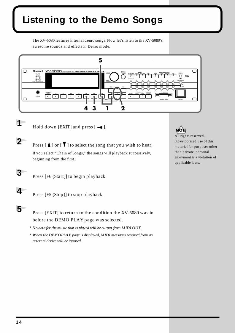
Listening to the Demo Songs
The XV-5080 features internal demo songs. Now let’s listen to the XV-5080’s awesome sounds and effects in Demo mode.
fig.00-012.e_80
1 Hold down [EXIT] and press [ ].
2 Press [ ] or [ ] to select the song that you wish to hear.
If you select “Chain of Songs,” the songs will playback successively, beginning from the first.
3 Press [F6 (Start)] to begin playback.
4 Press [F5 (Stop)] to stop playback.
5 Press [EXIT] to return to the condition the XV-5080 was in before the DEMO PLAY page was selected.
* No data for the music that is played will be output from MIDI OUT.
* When the DEMOPLAY page is displayed, MIDI messages received from an
external device will be ignored.
All rights reserved. Unauthorized use of this material for purposes other than private, personal enjoyment is a violation of applicable laws.
4
Try Out the Sounds
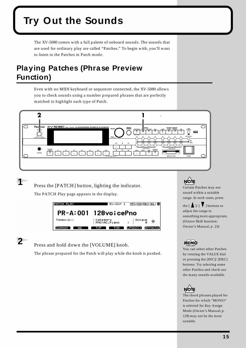
The XV-5080 comes with a full palette of onboard sounds. The sounds that are used for ordinary play are called “Patches.” To begin with, you’ll want to listen to the Patches in Patch mode.
Playing Patches (Phrase Preview Function)
Even with no MIDI keyboard or sequencer connected, the XV-5080 allows you to check sounds using a number prepared phrases that are perfectly matched to highlight each type of Patch.
fig.00-014.e_80
1 Press the [PATCH] button, lighting the indicator.
The PATCH Play page appears in the display.fig.00-015.e_80
2 Press and hold down the [VOLUME] knob.
The phrase prepared for the Patch will play while the knob is pushed.
Certain Patches may not sound within a suitable range. In such cases, press
the [ ]/[ ] buttons to adjust the range to something more appropriate. (Octave Shift function: Owner’s Manual, p. 23)
You can select other Patches by rotating the VALUE dial or pressing the [INC]/[DEC] buttons. Try selecting some other Patches and check out the many sounds available.
The chord phrases played for Patches for which “MONO” is selected for Key Assign Mode (Owner’s Manual; p. 129) may not be the most suitable.
15
Try Out the Sounds
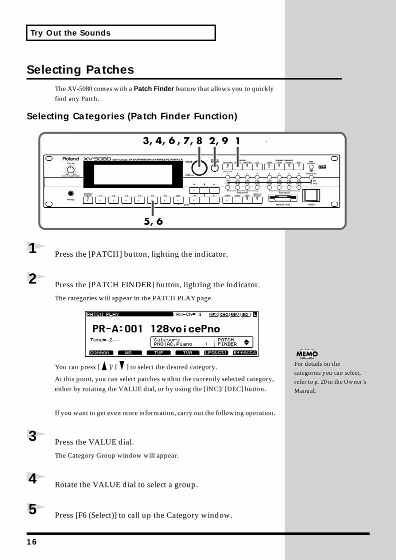
Selecting PatchesThe XV-5080 comes with a Patch Finder feature that allows you to quickly find any Patch.
Selecting Categories (Patch Finder Function)fig.00-016.e_80
1 Press the [PATCH] button, lighting the indicator.
2 Press the [PATCH FINDER] button, lighting the indicator.
The categories will appear in the PATCH PLAY page.fig.00-017.e_80
You can press [ ]/[ ] to select the desired category.
At this point, you can select patches within the currently selected category, either by rotating the VALUE dial, or by using the [INC]/[DEC] button.
If you want to get even more information, carry out the following operation.
3 Press the VALUE dial.
The Category Group window will appear.
4 Rotate the VALUE dial to select a group.
5 Press [F6 (Select)] to call up the Category window.
For details on the categories you can select, refer to p. 20 in the Owner’s Manual.
16
Try Out the Sounds
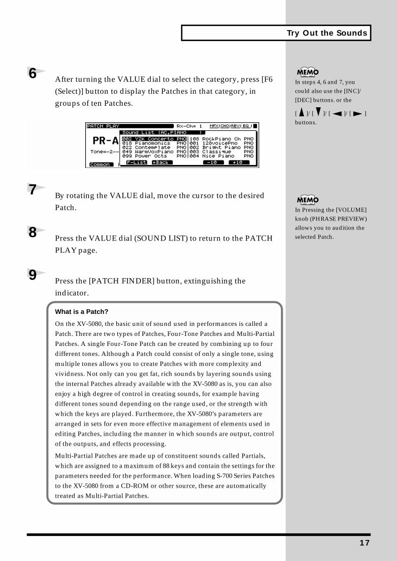
6 After turning the VALUE dial to select the category, press [F6 (Select)] button to display the Patches in that category, in groups of ten Patches.
7 By rotating the VALUE dial, move the cursor to the desired Patch.
8 Press the VALUE dial (SOUND LIST) to return to the PATCH PLAY page.
9 Press the [PATCH FINDER] button, extinguishing the indicator.
In steps 4, 6 and 7, you could also use the [INC]/[DEC] buttons. or the
[ ]/[ ]/[ ]/[ ] buttons.
In Pressing the [VOLUME] knob (PHRASE PREVIEW) allows you to audition the selected Patch.
What is a Patch?
On the XV-5080, the basic unit of sound used in performances is called a Patch. There are two types of Patches, Four-Tone Patches and Multi-Partial Patches. A single Four-Tone Patch can be created by combining up to four different tones. Although a Patch could consist of only a single tone, using multiple tones allows you to create Patches with more complexity and vividness. Not only can you get fat, rich sounds by layering sounds using the internal Patches already available with the XV-5080 as is, you can also enjoy a high degree of control in creating sounds, for example having different tones sound depending on the range used, or the strength with which the keys are played. Furthermore, the XV-5080’s parameters are arranged in sets for even more effective management of elements used in editing Patches, including the manner in which sounds are output, control of the outputs, and effects processing.
Multi-Partial Patches are made up of constituent sounds called Partials, which are assigned to a maximum of 88 keys and contain the settings for the parameters needed for the performance. When loading S-700 Series Patches to the XV-5080 from a CD-ROM or other source, these are automatically treated as Multi-Partial Patches.
17
Try Out the Sounds
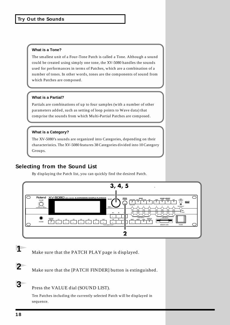
Selecting from the Sound ListBy displaying the Patch list, you can quickly find the desired Patch.
fig.00-018.e_80
1 Make sure that the PATCH PLAY page is displayed.
2 Make sure that the [PATCH FINDER] button is extinguished.
3 Press the VALUE dial (SOUND LIST).
Ten Patches including the currently selected Patch will be displayed in sequence.
What is a Tone?
The smallest unit of a Four-Tone Patch is called a Tone. Although a sound could be created using simply one tone, the XV-5080 handles the sounds used for performances in terms of Patches, which are a combination of a number of tones. In other words, tones are the components of sound from which Patches are composed.
What is a Partial?
Partials are combinations of up to four samples (with a number of other parameters added, such as setting of loop points to Wave data) that comprise the sounds from which Multi-Partial Patches are composed.
What is a Category?
The XV-5080’s sounds are organized into Categories, depending on their characteristics. The XV-5080 features 38 Categories divided into 10 Category Groups.
18

Try Out the Sounds
fig.00-019.e_80
[F3 (-Bank)]/[F4 (+Bank)]: Switches the banks.
[F5 (-10)]/[F6 (+10)]: Switches the displayed Patched in steps of 10.
4 By rotating the VALUE dial, move the cursor to the desired Patch.
5 Press the VALUE dial (SOUND LIST) to return to the PATCH PLAY page.
Making Selections with Basic Operationsfig.00-020.e
On the PATCH PLAY page
Selecting with the VALUE DialRotate the VALUE dial to select. Holding down the VALUE dial while rotating it changes the value by tens (the value can be similarly changed by tens by holding down the [SHIFT] button while rotating the VALUE dial).
Selecting with the [INC] and [DEC] ButtonsPress the [INC]/[DEC] buttons to select. Holding down one button while pressing the other changes the value more rapidly.
Holding down the [SHIFT] button while pressing the [INC]/[DEC] button changes the value by tens.
When the [INC]/[DEC] button is held down continuously, the value stops at the top (001) of the current bank (A–H). To advance to the next bank, release the button then press it again.
In step 3, you could also use the [INC]/[DEC]
buttons, or the [ ]/[ ]/
[ ]/[ ] buttons.
SHIFT buttonINC/DEC button
VALUE dial
19
Try Out the Sounds
Switching ModesIn addition to Patch mode, the XV-5080 also features three other modes: Performance mode, Rhythm Set mode, and GM2 mode. Let’s try switching the modes and listen to the sounds in each one.
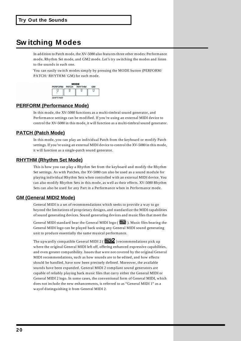
You can easily switch modes simply by pressing the MODE button (PERFORM/PATCH/RHYTHM/GM) for each mode.
fig.00-021.e
PERFORM (Performance Mode)In this mode, the XV-5080 functions as a multi-timbral sound generator, and Performance settings can be modified. If you’re using an external MIDI device to control the XV-5080 in this mode, it will function as a multi-timbral sound generator.
PATCH (Patch Mode)In this mode, you can play an individual Patch from the keyboard or modify Patch settings. If you’re using an external MIDI device to control the XV-5080 in this mode, it will function as a single-patch sound generator.
RHYTHM (Rhythm Set Mode)This is how you can play a Rhythm Set from the keyboard and modify the Rhythm Set settings. As with Patches, the XV-5080 can also be used as a sound module for playing individual Rhythm Sets when controlled with an external MIDI device. You can also modify Rhythm Sets in this mode, as well as their effects. XV-5080 Rhythm Sets can also be used for any Part in a Performance when in Performance mode.
GM (General MIDI2 Mode)General MIDI is a set of recommendations which seeks to provide a way to go beyond the limitations of proprietary designs, and standardize the MIDI capabilities of sound generating devices. Sound generating devices and music files that meet the
General MIDI standard bear the General MIDI logo ( ). Music files bearing the General MIDI logo can be played back using any General MIDI sound generating unit to produce essentially the same musical performance.
The upwardly compatible General MIDI 2 ( ) recommendations pick up where the original General MIDI left off, offering enhanced expressive capabilities, and even greater compatibility. Issues that were not covered by the original General MIDI recommendations, such as how sounds are to be edited, and how effects should be handled, have now been precisely defined. Moreover, the available sounds have been expanded. General MIDI 2 compliant sound generators are capable of reliably playing back music files that carry either the General MIDI or General MIDI 2 logo. In some cases, the conventional form of General MIDI, which does not include the new enhancements, is referred to as “General MIDI 1” as a wayof distinguishing it from General MIDI 2.
20
Try Out the Sounds
Selecting Sound LibrariesOn the XV-5080, tone data is stored in what are called “SOUND LIBRARY.” The SOUND LIBRARY is divided into four “groups”: USER, CARD, PRESET, and EXP.
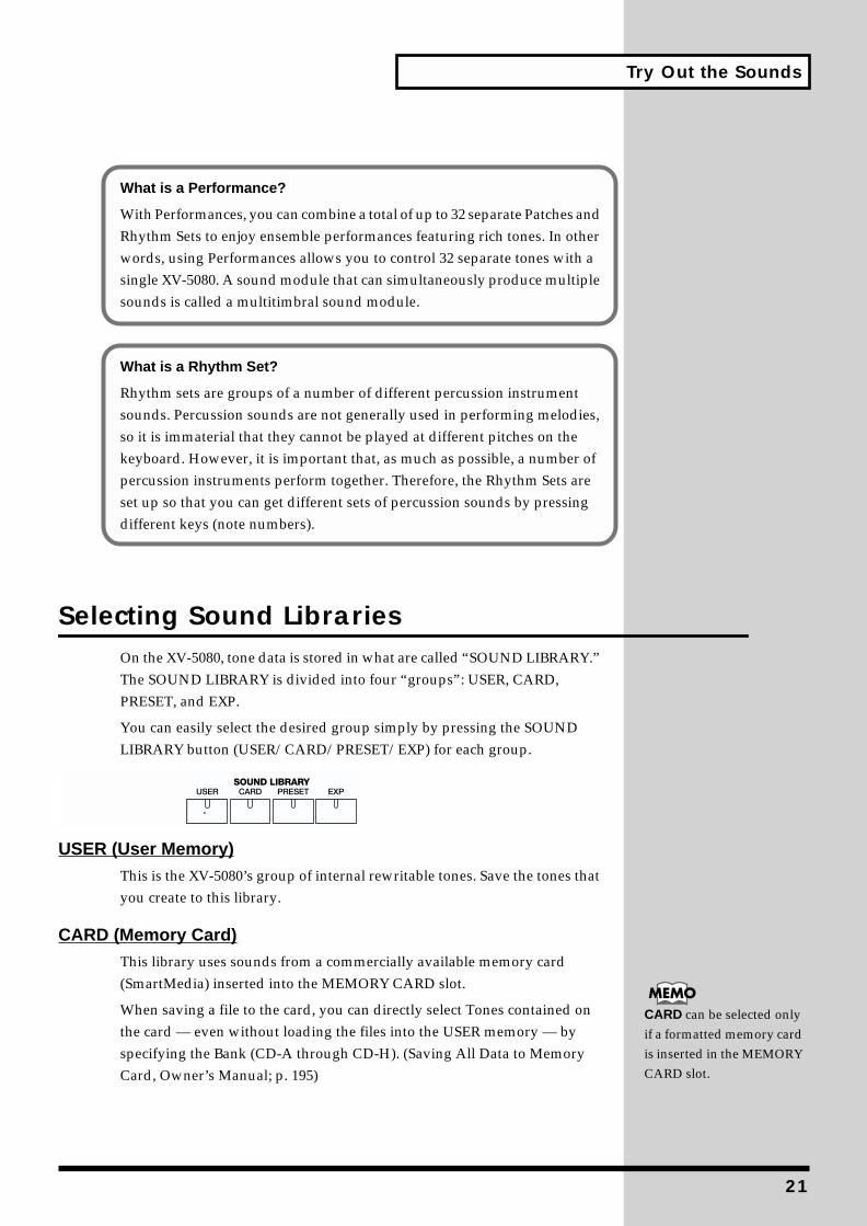
You can easily select the desired group simply by pressing the SOUND LIBRARY button (USER/CARD/PRESET/EXP) for each group.
fig.00-022.e
USER (User Memory)This is the XV-5080’s group of internal rewritable tones. Save the tones that you create to this library.
CARD (Memory Card)This library uses sounds from a commercially available memory card (SmartMedia) inserted into the MEMORY CARD slot.
When saving a file to the card, you can directly select Tones contained on the card — even without loading the files into the USER memory — by specifying the Bank (CD-A through CD-H). (Saving All Data to Memory Card, Owner’s Manual; p. 195)
What is a Performance?
With Performances, you can combine a total of up to 32 separate Patches and Rhythm Sets to enjoy ensemble performances featuring rich tones. In other words, using Performances allows you to control 32 separate tones with a single XV-5080. A sound module that can simultaneously produce multiple sounds is called a multitimbral sound module.
What is a Rhythm Set?
Rhythm sets are groups of a number of different percussion instrument sounds. Percussion sounds are not generally used in performing melodies, so it is immaterial that they cannot be played at different pitches on the keyboard. However, it is important that, as much as possible, a number of percussion instruments perform together. Therefore, the Rhythm Sets are set up so that you can get different sets of percussion sounds by pressing different keys (note numbers).
CARD can be selected only if a formatted memory card is inserted in the MEMORY CARD slot.
21
Try Out the Sounds
PRESET (Preset Memory)The PRESET library group contains the sounds that are permanently stored in the XV-5080’s memory.
EXP (Wave Expansion Board)Select this group to use the tones stored on wave expansion boards (SRX Series, SR-JV80 Series; sold separately) inserted in the EXP-A through -H slots.
To select an installed wave expansion board, press the [A]–[H] button.
The EXP-A through EXP-D slots are for cards from the SR-JV80 Series. The EXP-E through EXP-H slots are for SRX Series boards.
Playing Sounds Using a MIDI KeyboardNow, try connecting your MIDI keyboard and playing sounds from the XV-5080.
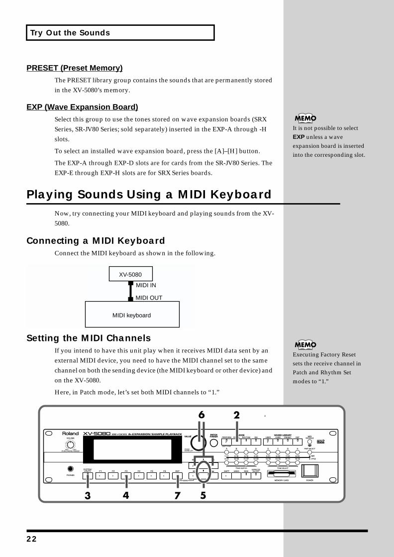
Connecting a MIDI KeyboardConnect the MIDI keyboard as shown in the following.
fig.00-023.e
Setting the MIDI ChannelsIf you intend to have this unit play when it receives MIDI data sent by an external MIDI device, you need to have the MIDI channel set to the same channel on both the sending device (the MIDI keyboard or other device) and on the XV-5080.
Here, in Patch mode, let’s set both MIDI channels to “1.”fig.00-024.e_80
It is not possible to select EXP unless a wave expansion board is inserted into the corresponding slot.
XV-5080
MIDI keyboard
MIDI IN
MIDI OUT
Executing Factory Reset sets the receive channel in Patch and Rhythm Set modes to “1.”
22
Try Out the Sounds
1 Set the send channel of the sending MIDI keyboard to “1.”
For instructions on making this setting, refer to the owner’s manual for the MIDI keyboard.
2 Press the [PATCH] button, lighting the indicator.
* As the receive channel is set to “1” when Factory Reset is executed, the following
step is not necessary.
Now play the MIDI keyboard to produce the sounds.
3 Press the [SYSTEM] button, lighting the indicator.
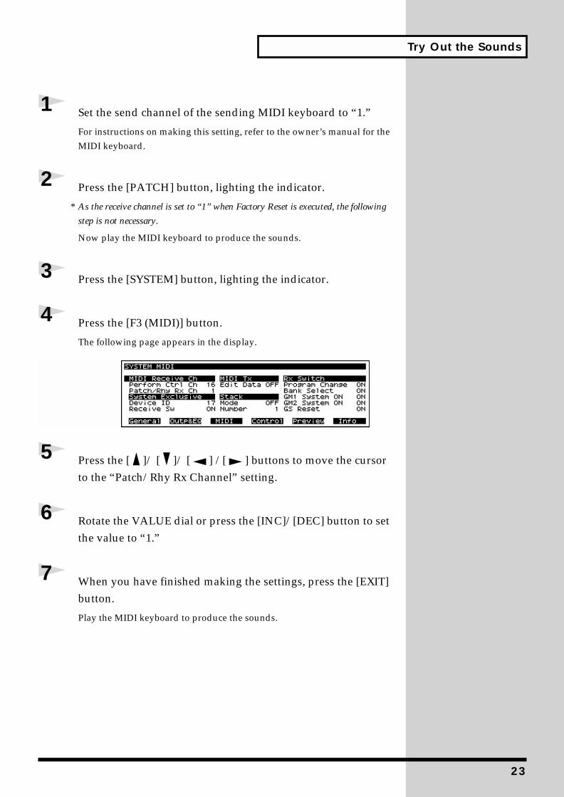
4 Press the [F3 (MIDI)] button.
The following page appears in the display.fig.00-025.e_80
5 Press the [ ]/ [ ]/ [ ] /[ ] buttons to move the cursor to the “Patch/Rhy Rx Channel” setting.
6 Rotate the VALUE dial or press the [INC]/[DEC] button to set the value to “1.”
7 When you have finished making the settings, press the [EXIT] button.
Play the MIDI keyboard to produce the sounds.
23
Try Out the Sounds
Playing Multiple Layered Patches (Layer)
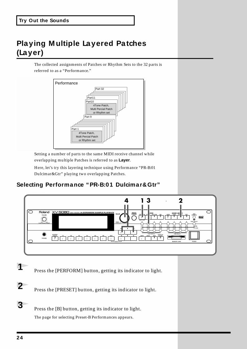
The collected assignments of Patches or Rhythm Sets to the 32 parts is referred to as a “Performance.”
fig.00-026.e
Setting a number of parts to the same MIDI receive channel while overlapping multiple Patches is referred to as Layer.
Here, let’s try this layering technique using Performance “PR-B:01 Dulcimar&Gtr” playing two overlapping Patches.
Selecting Performance “PR-B:01 Dulcimar&Gtr”fig.00-027.e_80
1 Press the [PERFORM] button, getting its indicator to light.
2 Press the [PRESET] button, getting its indicator to light.
3 Press the [B] button, getting its indicator to light.
The page for selecting Preset-B Performances appears.
Performance
Part 1
Part 9
Part 10
Part11
Part 32
4Tone Patch, Multi Percial Patch
or Rhythm set
4Tone Patch, Multi Percial Patch
or Rhythm set
24
Try Out the Sounds
fig.00-028.e_80
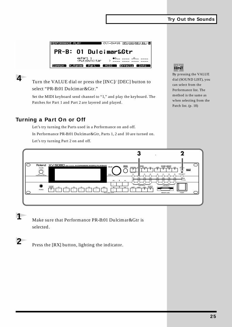
4 Turn the VALUE dial or press the [INC]/[DEC] button to select “PR-B:01 Dulcimar&Gtr.”
Set the MIDI keyboard send channel to “1,” and play the keyboard. The Patches for Part 1 and Part 2 are layered and played.
Turning a Part On or OffLet’s try turning the Parts used in a Performance on and off.
In Performance PR-B:01 Dulcimar&Gtr, Parts 1, 2 and 10 are turned on.
Let’s try turning Part 2 on and off.fig.00-029.e_80
1 Make sure that Performance PR-B:01 Dulcimar&Gtr is selected.
2 Press the [RX] button, lighting the indicator.
By pressing the VALUE dial (SOUND LIST), you can select from the Performance list. The method is the same as when selecting from the Patch list. (p. 18)
25
Try Out the Sounds
3 Make sure that the [1-16/17-32] indicator is dark, and then press the PART SELECT [2/18] button to make the indicator go dark (off).
fig.00-030.e_80
4 When you press the same button again, the indicator lights and turns Part 2 back on.
Assigning a different Patch to a PartThis is how to change the Patch assigned to a Part in a Performance.
Here, we will switch the Patch in Part 2 of the Performance PR-A:01Seq:Template to 018 (Slap Bass).
fig.00-031.e_80
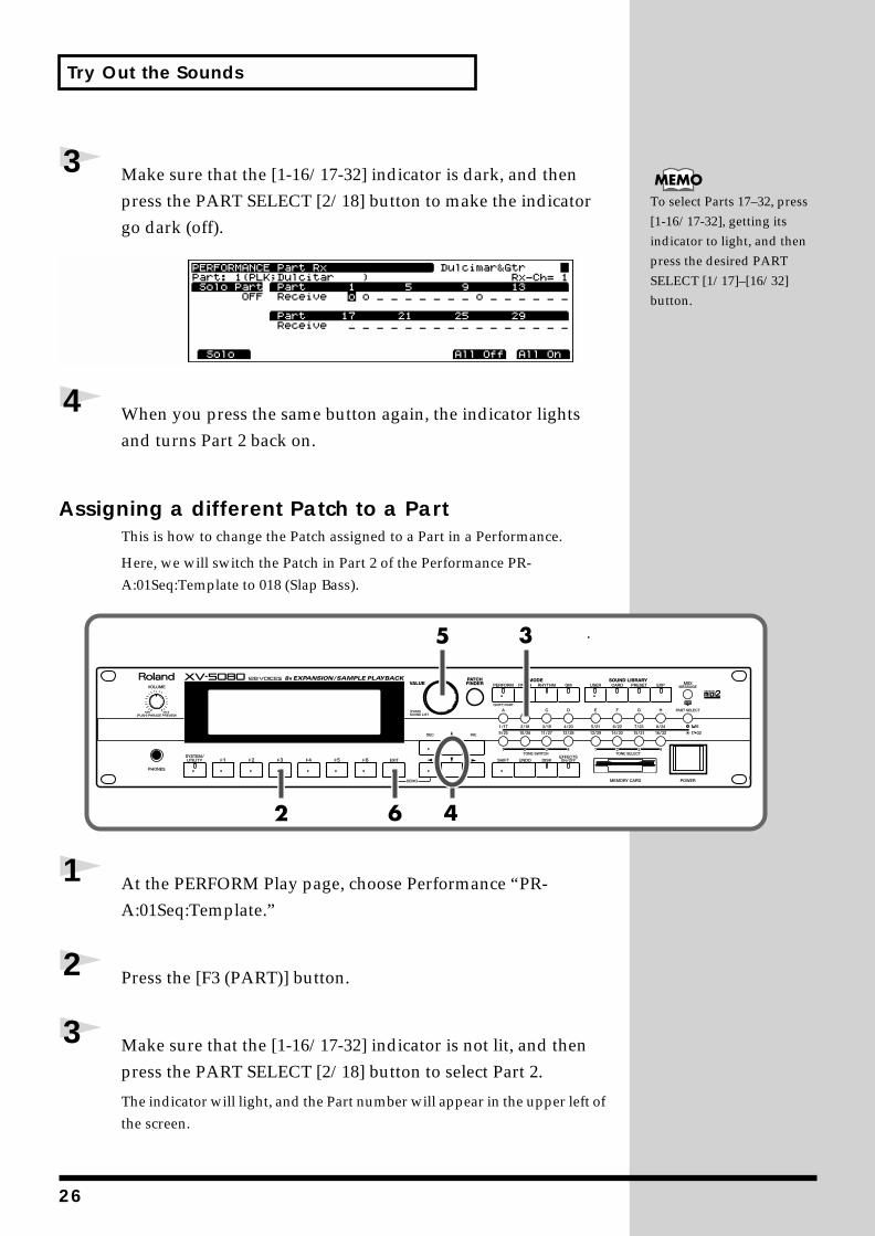
1 At the PERFORM Play page, choose Performance “PR-A:01Seq:Template.”
2 Press the [F3 (PART)] button.
3 Make sure that the [1-16/17-32] indicator is not lit, and then press the PART SELECT [2/18] button to select Part 2.
The indicator will light, and the Part number will appear in the upper left of the screen.
To select Parts 17–32, press [1-16/17-32], getting its indicator to light, and then press the desired PART SELECT [1/17]–[16/32] button.
26
Try Out the Sounds
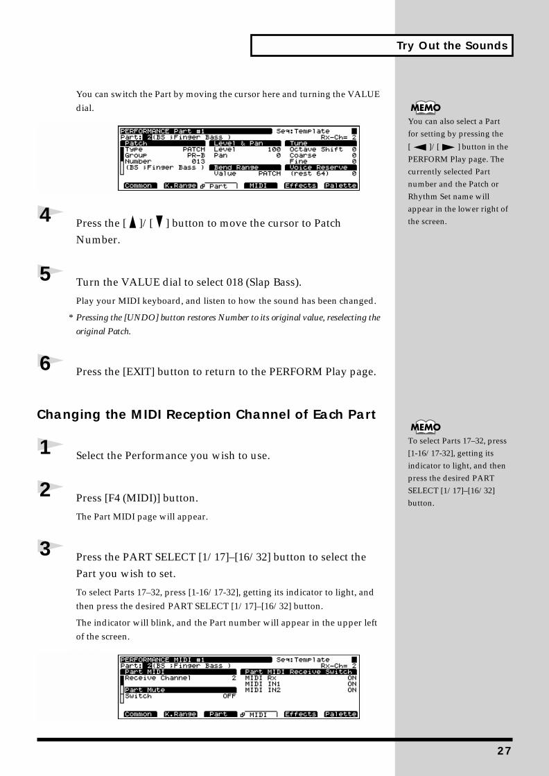
You can switch the Part by moving the cursor here and turning the VALUE dial.
fig.00-032.e_80
4 Press the [ ]/[ ] button to move the cursor to Patch Number.
5 Turn the VALUE dial to select 018 (Slap Bass).
Play your MIDI keyboard, and listen to how the sound has been changed.
* Pressing the [UNDO] button restores Number to its original value, reselecting the
original Patch.
6 Press the [EXIT] button to return to the PERFORM Play page.
Changing the MIDI Reception Channel of Each Part
1 Select the Performance you wish to use.
2 Press [F4 (MIDI)] button.
The Part MIDI page will appear.
3 Press the PART SELECT [1/17]–[16/32] button to select the Part you wish to set.
To select Parts 17–32, press [1-16/17-32], getting its indicator to light, and then press the desired PART SELECT [1/17]–[16/32] button.
The indicator will blink, and the Part number will appear in the upper left of the screen.
fig.00-033.e_80
To select Parts 17–32, press [1-16/17-32], getting its indicator to light, and then press the desired PART SELECT [1/17]–[16/32] button.
You can also select a Part for setting by pressing the
[ ]/[ ] button in the PERFORM Play page. The currently selected Part number and the Patch or Rhythm Set name will appear in the lower right of the screen.
27
Try Out the Sounds
4 Press the [ ]/[ ] button to move the cursor to the “Receive Channel” setting.
5 Turn the VALUE dial or press the [INC]/[DEC] button to select the desired MIDI channel.
6 Press the [EXIT] button to return to the PERFORM Play page.
Having Different Patches Play In Separate Ranges of the Keyboard (Split)
In a Performance, by selecting the same MIDI receive channel for a number of parts and then changing the pitch range over which each part is to be played, you can thus divide the keyboard into separate ranges and assign a different Patch to each range. This is referred to as a Split.
The split is one application of the layer technique (Playing Multiple Layered Patches). The split works by changing the sounding range of each patches of the layered parts.
Now, try a creating a split using Performance “PR-B:29 Organ/Lead.”
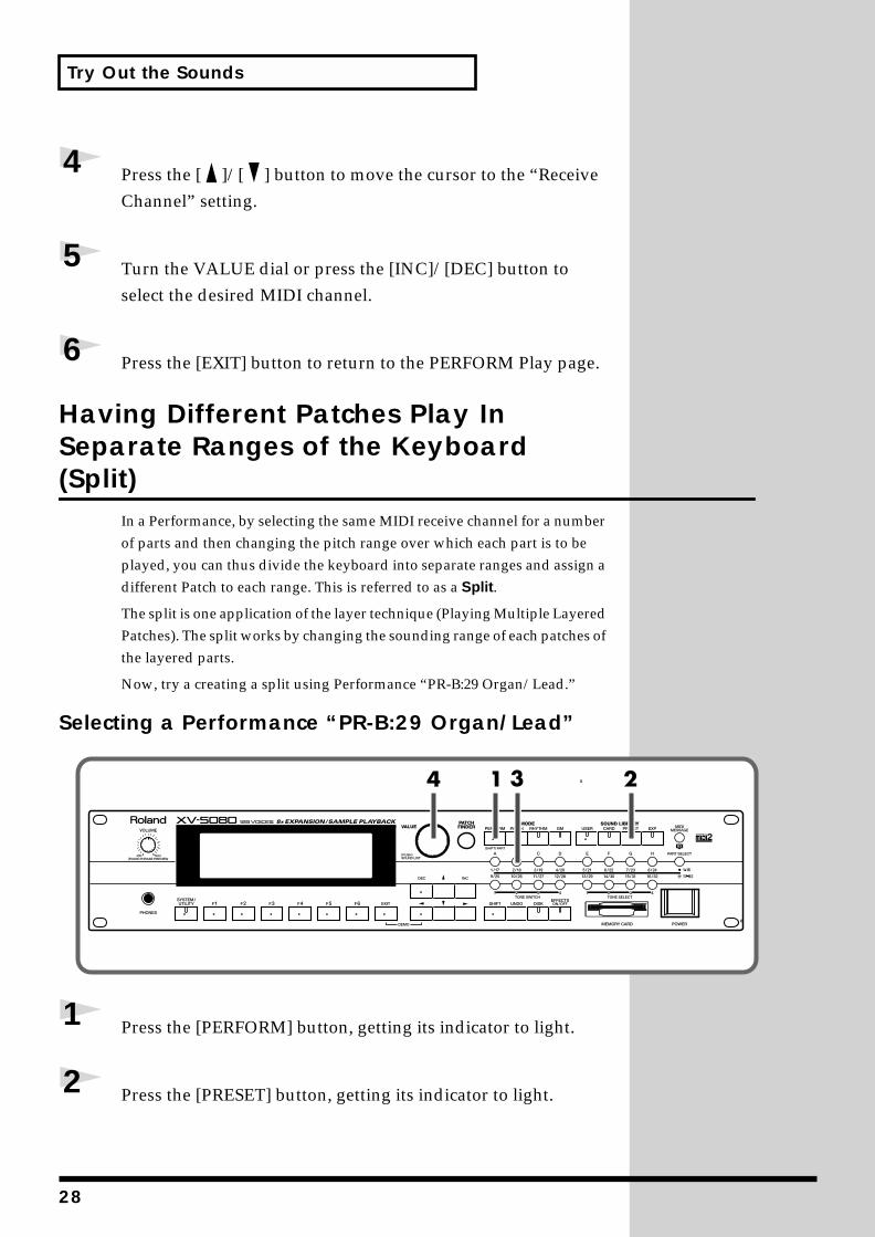
Selecting a Performance “PR-B:29 Organ/Lead”fig.00-034.e_80
1 Press the [PERFORM] button, getting its indicator to light.
2 Press the [PRESET] button, getting its indicator to light.
28
Try Out the Sounds
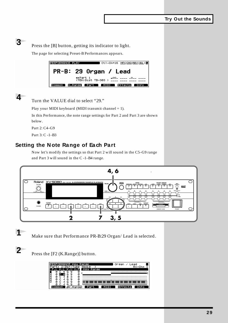
3 Press the [B] button, getting its indicator to light.
The page for selecting Preset-B Performances appears.fig.00-035.e_80
4 Turn the VALUE dial to select “29.”
Play your MIDI keyboard (MIDI transmit channel = 1).
In this Performance, the note range settings for Part 2 and Part 3 are shown below.
Part 2: C4–G9
Part 3: C -1–B3
Setting the Note Range of Each PartNow let’s modify the settings so that Part 2 will sound in the C5–G9 range and Part 3 will sound in the C -1–B4 range.
fig.00-036.e_80
1 Make sure that Performance PR-B:29 Organ/Lead is selected.
2 Press the [F2 (K.Range)] button.fig.00-037.e_80
29
Try Out the Sounds
3 Press [ ]/[ ]/[ ]/[ ] to move the cursor to K.L of Part 2.
4 Turn the VALUE dial to select “C5.”
5 Press [ ]/[ ]/[ ]/[ ] to move the cursor to K.U of Part 3.
6 Turn the VALUE dial to select “B4.”
7 Press the [EXIT] button to return to the PERFORM PLAY page.
Play your MIDI keyboard and notice how the Parts’ ranges have changed.
Try Using an External MIDI Device to Switch Patches and Other Settings
Using an External MIDI Device to Switch Patches and Rhythm Sets
By receiving MIDI messages, the XV-5080 can switch Patches (including the Patches for each Part of a Performance) or Rhythm Sets.
Here, after setting the send channel for the external MIDI device and the XV-5080’s receive channel (??Patch/Rhy Rx Ch??) to “1,” try sending a MIDI message from the external MIDI device to switch the XV-5080’s Patch to PR-A:002 Bright Piano.
1 Use a MIDI cable to connect the the MIDI OUT connector of the external MIDI device to MIDI IN connector of the XV-5080.
2 Press the [PATCH] button, lighting the indicator.
3 Set the channel used for transmission by the external MIDI device and the XV-5080’s receive channel to the same channel. (See p. 22.)
Since the receive channel is always set to “1” when a Factory Reset is
30
Try Out the Sounds
executed, it may not be necessary to set the receive channel.
4 Send a Bank Select MSB (Control Number 0) value of “87” to the XV-5080.
If you want to switch Rhythm Sets, send “86” as the value.
5 Next, send a Bank Select LSB (Control Number 32) value of “64.”
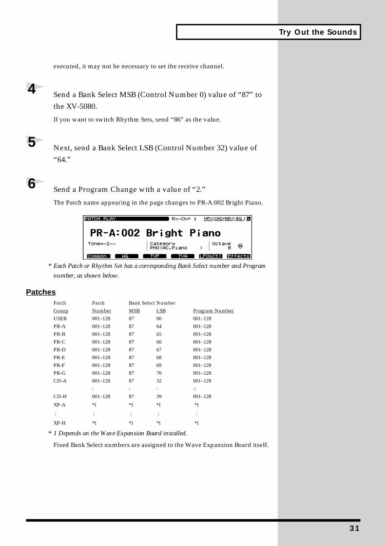
6 Send a Program Change with a value of “2.”
The Patch name appearing in the page changes to PR-A:002 Bright Piano.fig.00-038.e_80
* Each Patch or Rhythm Set has a corresponding Bank Select number and Program
number, as shown below.
PatchesPatch Patch Bank Select NumberGroup Number MSB LSB Program NumberUSER 001–128 87 00 001–128PR-A 001–128 87 64 001–128PR-B 001–128 87 65 001–128PR-C 001–128 87 66 001–128PR-D 001–128 87 67 001–128PR-E 001–128 87 68 001–128PR-F 001–128 87 69 001–128PR-G 001–128 87 70 001–128CD-A 001–128 87 32 001–128
: : : ::CD-H 001–128 87 39 001–128
XP-A *1 *1 *1 *1
: : : : :
XP-H *1 *1 *1 *1
* 1 Depends on the Wave Expansion Board installed.
Fixed Bank Select numbers are assigned to the Wave Expansion Board itself.
31
Try Out the Sounds
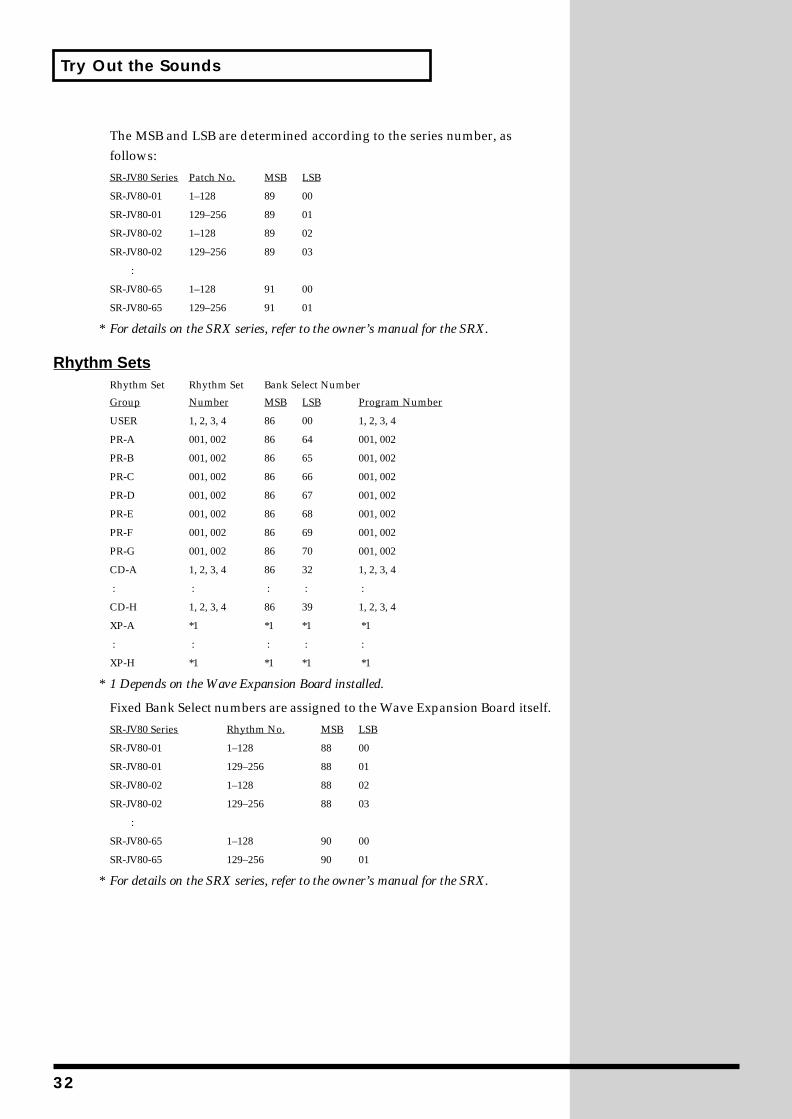
The MSB and LSB are determined according to the series number, as follows:
SR-JV80 Series Patch No. MSB LSB
SR-JV80-01 1–128 89 00
SR-JV80-01 129–256 89 01
SR-JV80-02 1–128 89 02
SR-JV80-02 129–256 89 03
:
SR-JV80-65 1–128 91 00
SR-JV80-65 129–256 91 01
* For details on the SRX series, refer to the owner’s manual for the SRX.
Rhythm SetsRhythm Set Rhythm Set Bank Select Number
Group Number MSB LSB Program Number
USER 1, 2, 3, 4 86 00 1, 2, 3, 4
PR-A 001, 002 86 64 001, 002
PR-B 001, 002 86 65 001, 002
PR-C 001, 002 86 66 001, 002
PR-D 001, 002 86 67 001, 002
PR-E 001, 002 86 68 001, 002
PR-F 001, 002 86 69 001, 002
PR-G 001, 002 86 70 001, 002
CD-A 1, 2, 3, 4 86 32 1, 2, 3, 4
: : : : :
CD-H 1, 2, 3, 4 86 39 1, 2, 3, 4
XP-A *1 *1 *1 *1
: : : : :
XP-H *1 *1 *1 *1
* 1 Depends on the Wave Expansion Board installed.
Fixed Bank Select numbers are assigned to the Wave Expansion Board itself.
SR-JV80 Series Rhythm No. MSB LSB
SR-JV80-01 1–128 88 00
SR-JV80-01 129–256 88 01
SR-JV80-02 1–128 88 02
SR-JV80-02 129–256 88 03
:
SR-JV80-65 1–128 90 00
SR-JV80-65 129–256 90 01
* For details on the SRX series, refer to the owner’s manual for the SRX.
32
Try Out the Sounds
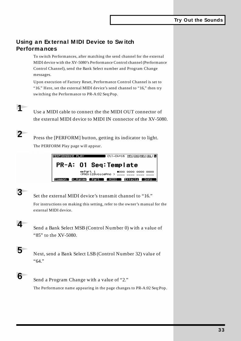
Using an External MIDI Device to Switch Performances
To switch Performances, after matching the send channel for the external MIDI device with the XV-5080’s Performance Control channel (Performance Control Channel), send the Bank Select number and Program Change messages.
Upon execution of Factory Reset, Performance Control Channel is set to “16.” Here, set the external MIDI device’s send channel to “16,” then try switching the Performance to PR-A:02 Seq:Pop.
1 Use a MIDI cable to connect the the MIDI OUT connector of the external MIDI device to MIDI IN connector of the XV-5080.
2 Press the [PERFORM] button, getting its indicator to light.
The PERFORM Play page will appear.fig.00-039.e_80
3 Set the external MIDI device’s transmit channel to “16.”
For instructions on making this setting, refer to the owner’s manual for the external MIDI device.
4 Send a Bank Select MSB (Control Number 0) with a value of “85” to the XV-5080.
5 Next, send a Bank Select LSB (Control Number 32) value of “64.”
6 Send a Program Change with a value of “2.”
The Performance name appearing in the page changes to PR-A:02 Seq:Pop.
33
Try Out the Sounds
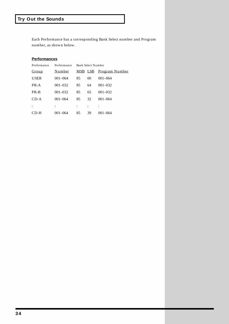
Each Performance has a corresponding Bank Select number and Program number, as shown below.
Performances
Performance Performance Bank Select Number
Group Number MSB LSB Program Number
USER 001–064 85 00 001–064
PR-A 001–032 85 64 001–032
PR-B 001–032 85 65 001–032
CD-A 001–064 85 32 001–064
: : : : :
CD-H 001–064 85 39 001–064
34
Turning Effects On and Off
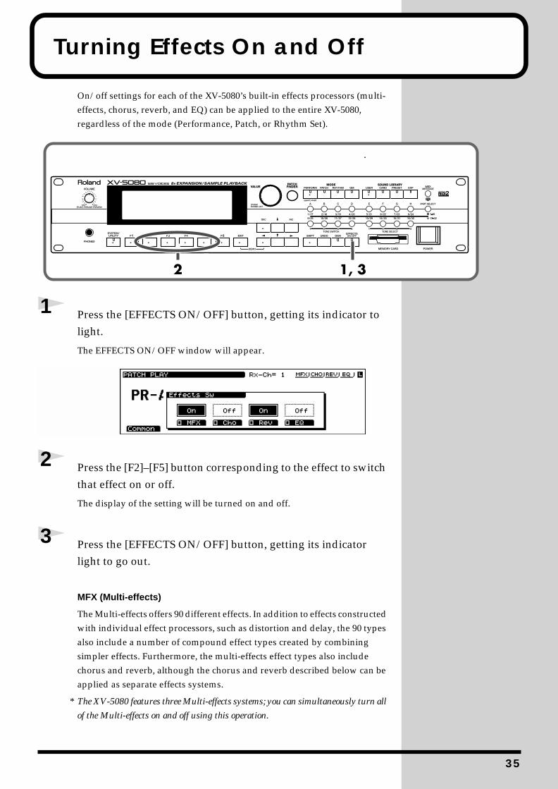
On/off settings for each of the XV-5080’s built-in effects processors (multi-effects, chorus, reverb, and EQ) can be applied to the entire XV-5080, regardless of the mode (Performance, Patch, or Rhythm Set).
fig.00-040.e_80
1 Press the [EFFECTS ON/OFF] button, getting its indicator to light.
The EFFECTS ON/OFF window will appear.fig.00-041.e_80
2 Press the [F2]–[F5] button corresponding to the effect to switch that effect on or off.
The display of the setting will be turned on and off.
3 Press the [EFFECTS ON/OFF] button, getting its indicator light to go out.
MFX (Multi-effects)
The Multi-effects offers 90 different effects. In addition to effects constructed with individual effect processors, such as distortion and delay, the 90 types also include a number of compound effect types created by combining simpler effects. Furthermore, the multi-effects effect types also include chorus and reverb, although the chorus and reverb described below can be applied as separate effects systems.
* The XV-5080 features three Multi-effects systems; you can simultaneously turn all
of the Multi-effects on and off using this operation.
35
Turning Effects On and Off
Chorus
Chorus adds depth and spaciousness to the sound.
Reverb
Reverb is an effect that adds reverberation resembling that created when sounds are played in a hall.
EQ
An equalizer lets you boost or cut specified frequency ranges of a sound to adjust the tone.
* Although you can add equalization to each of the XV-5080’s output jacks, this
operation turns the EQ for all of the outputs on and off simultaneously.
36
Let’s Play Sounds From a Sampler Library
Now let’s try loading a sampler library (such as the optional L-CDX Series) into the XV-5080 and playing some sounds.
Playing sampler libraries with the XV-5080 requires a SCSI-type CD-ROM drive, and commercially available SIMMs (memory modules).
* At least 16 MB (32 MB or more recommended) of additional memory is required.
Installing the SIMM (Memory Module)Loading commercial sampler libraries into the XV-5080 requires installation of a SIMM memory module. The XV-5080 is equipped with two slots for SIMMs, allowing you to expand memory capacity by 128 MB (with two 64-megabyte SIMMs installed).
SIMMs for use with the XV-5080 must match the following
specifications.
Number of pins: 72
Access time: 60 ns or faster
Access protocol: FPM or EDO
Voltage: 5 V
Capacity: 64 MB/32 MB/16 MB (can be mixed)
* Both parity and non-parity are supported.
SIMM Hight: 36 mm or lower
Cautions When Installing SIMM• To avoid the risk of damage to internal components that can be caused
by static electricity, please carefully observe the following whenever you handle the board.
❍ Before you touch the board, always first grasp a metal object (such as a water pipe), so you are sure that any static electricity you might have been carrying has been discharged.
❍ When handling the board, grasp it only by its edges. Avoid touching any of the electronic components or connectors.
❍ Save the bag in which the board was originally shipped, and put the board back into it whenever you need to store or transport it.
• Use a Philips screwdriver that is suitable for the size of the screw. If an unsuitable screwdriver is used, the head of the screw may be stripped.
• To remove a screw, rotate the screwdriver counter-clockwise. To tighten the screws, rotate the screwdriver clockwise.
fig.00-042.e
• Be careful not to cut your hands on the edges of the opening while removing the cover.
• When adding SIMMs, remove only the specified screws.
The Akai S1000/3000 CD-ROM sound libraries can also be loaded. For more on this, “Chapter 7 Loading Each Type of Data” in the Owner’s Manual.
tightenloosen
37
Let’s Play Sounds From a Sampler Library
• Be careful that the screws you remove do not drop into the interior of the XV-5080.
• Do not touch any of the printed circuit pathways or connection terminals.
• Never use excessive force when installing a circuit board. If it doesn’t fit properly on the first attempt, remove the board and try again.
• When circuit board installation is complete, double-check your work.
• Do not leave the cover removed. Be sure to reattach it after the SIMM has been installed.
1 Turn off the power on the XV-5080 and any connected devices, and disconnect any cables connected to the XV-5080.
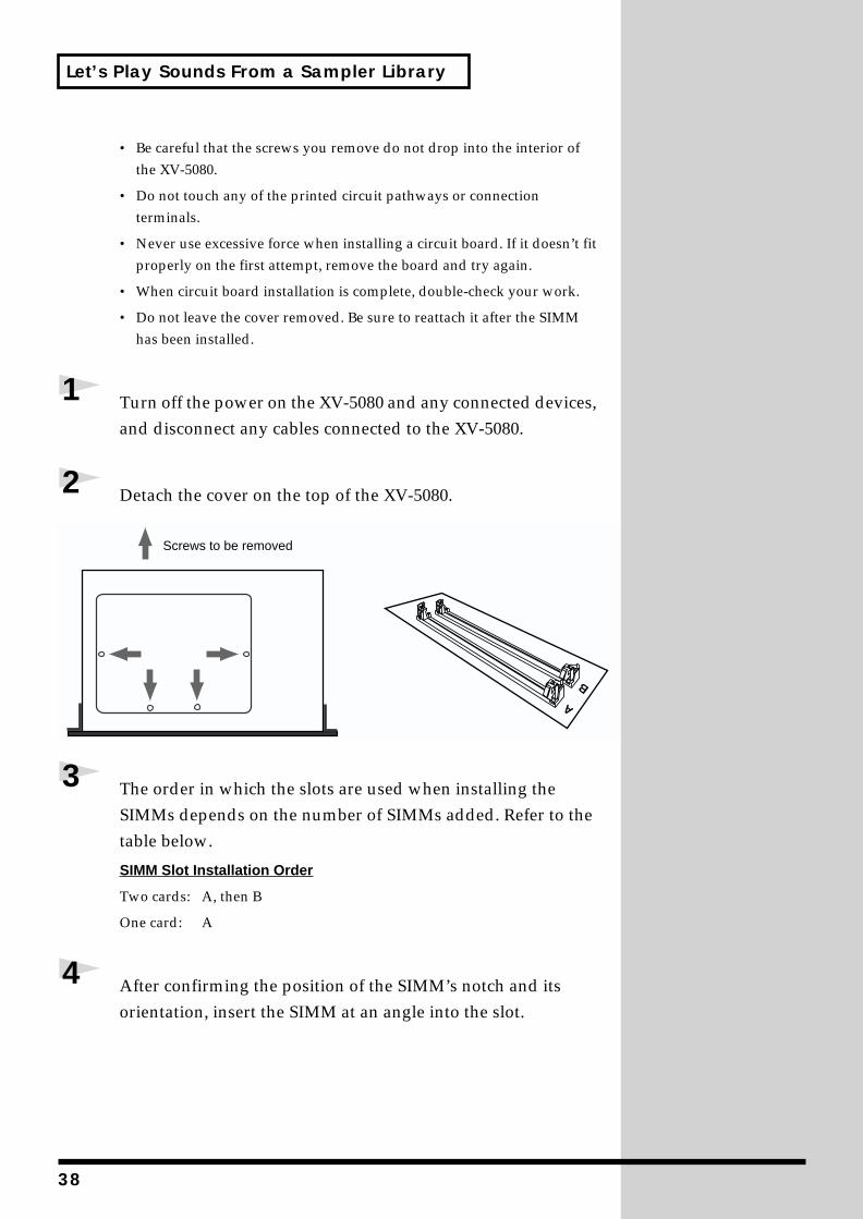
2 Detach the cover on the top of the XV-5080.fig.00-043.e
3 The order in which the slots are used when installing the SIMMs depends on the number of SIMMs added. Refer to the table below.
SIMM Slot Installation Order
Two cards: A, then B
One card: A
4 After confirming the position of the SIMM’s notch and its orientation, insert the SIMM at an angle into the slot.
A
B
Screws to be removed
38
Let’s Play Sounds From a Sampler Library
fig.00-044a.e
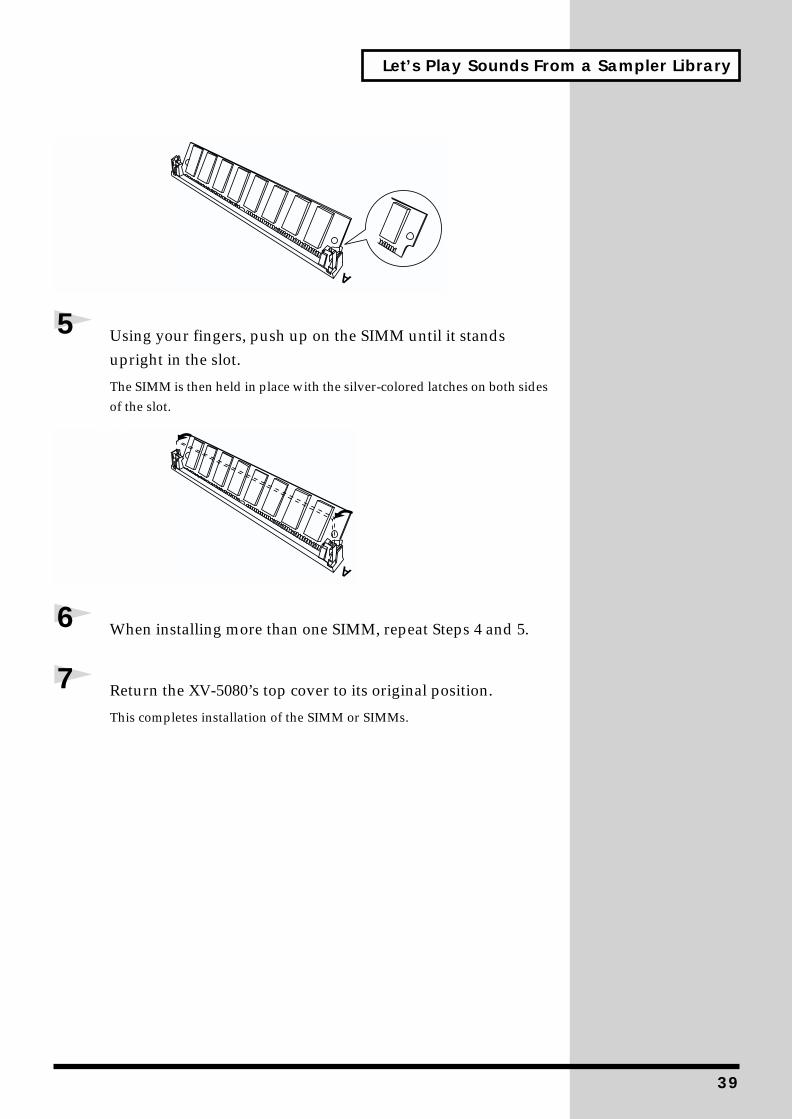
5 Using your fingers, push up on the SIMM until it stands upright in the slot.
The SIMM is then held in place with the silver-colored latches on both sides of the slot.
fig.00-044b.e
6 When installing more than one SIMM, repeat Steps 4 and 5.
7 Return the XV-5080’s top cover to its original position.
This completes installation of the SIMM or SIMMs.
A
A
39
Let’s Play Sounds From a Sampler Library
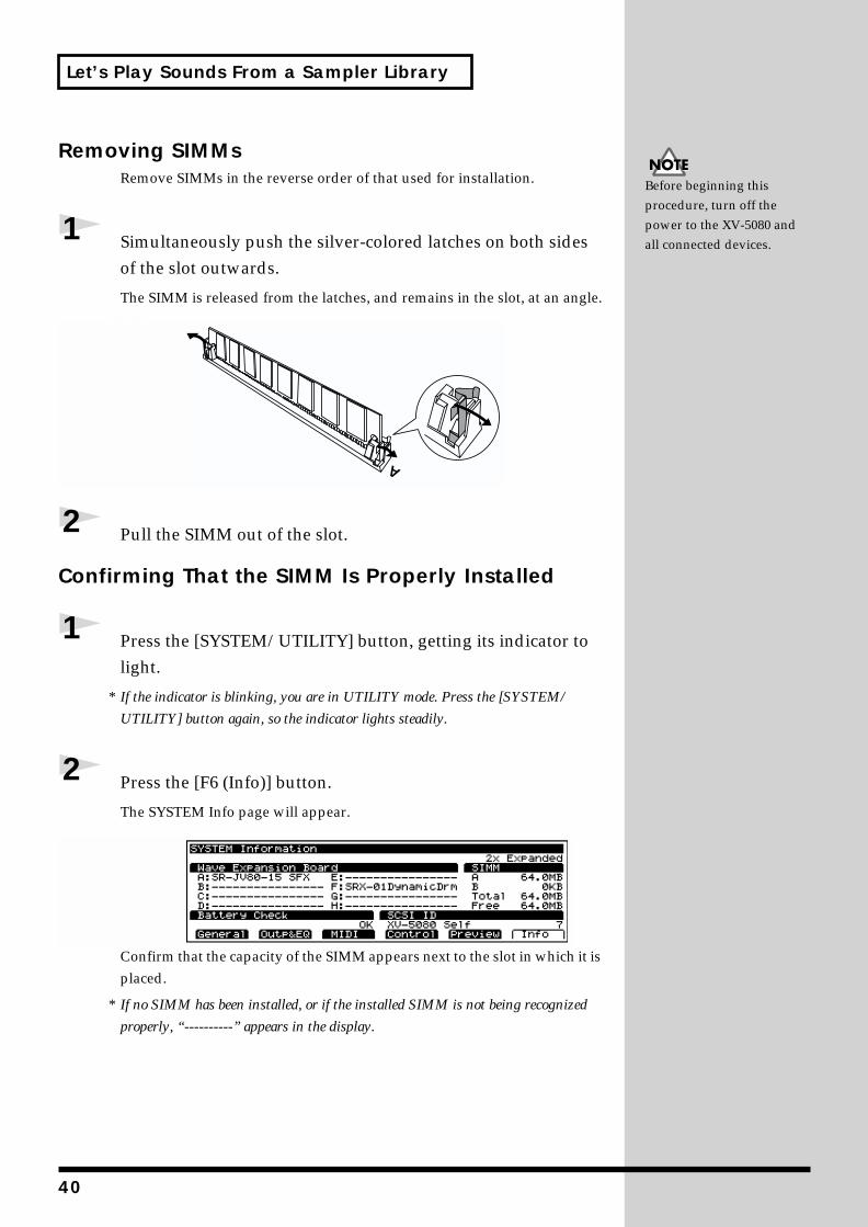
Removing SIMMsRemove SIMMs in the reverse order of that used for installation.
1 Simultaneously push the silver-colored latches on both sides of the slot outwards.
The SIMM is released from the latches, and remains in the slot, at an angle.fig.00-045.e
2 Pull the SIMM out of the slot.
Confirming That the SIMM Is Properly Installed
1 Press the [SYSTEM/UTILITY] button, getting its indicator to light.
* If the indicator is blinking, you are in UTILITY mode. Press the [SYSTEM/
UTILITY] button again, so the indicator lights steadily.
2 Press the [F6 (Info)] button.
The SYSTEM Info page will appear.fig.00-045a.e_80
Confirm that the capacity of the SIMM appears next to the slot in which it is placed.
* If no SIMM has been installed, or if the installed SIMM is not being recognized
properly, “----------” appears in the display.
Before beginning this procedure, turn off the power to the XV-5080 and all connected devices.
A
40
Let’s Play Sounds From a Sampler Library
Augmenter l
(French languag
Des modules SIMXV-5080 des biblLes deux fentes pl’expansion jusquchacun).
Vous pouvez ut
Nombre de broch
Temps d’accès :6
Méthode d’accès
Tension :5 V
Taille de la mém
* Compatible avec le
Hauteur des mod
Précautions à prend
• Veuillez suivrmanipulez la cpieces internes
❍
Toujours topar exempll’electricite
❍
Lorsque votoucher aux
❍
Conservez let remettez
• Choisir un toutournevis qui la tête des vis.
• Faire tourner lmontre pour ddes aiguilles d
fig.T01-001-expF
• Attention de nlorsque la plaq
desserrer
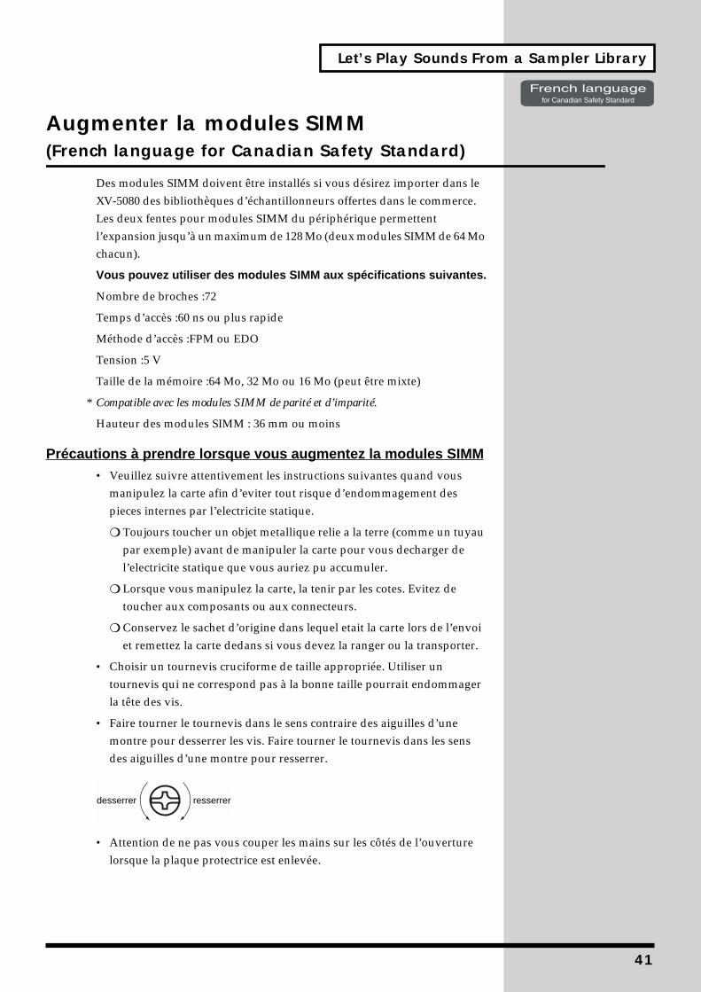
a modules SIMM e for Canadian Safety Standard)
M doivent être installés si vous désirez importer dans le iothèques d’échantillonneurs offertes dans le commerce. our modules SIMM du périphérique permettent ’à un maximum de 128 Mo (deux modules SIMM de 64 Mo
iliser des modules SIMM aux spécifications suivantes.
es :72
0 ns ou plus rapide
:FPM ou EDO
oire :64 Mo, 32 Mo ou 16 Mo (peut être mixte)
s modules SIMM de parité et d’imparité.
ules SIMM : 36 mm ou moins
re lorsque vous augmentez la modules SIMMe attentivement les instructions suivantes quand vous arte afin d’eviter tout risque d’endommagement des par l’electricite statique.
ucher un objet metallique relie a la terre (comme un tuyau e) avant de manipuler la carte pour vous decharger de statique que vous auriez pu accumuler.
us manipulez la carte, la tenir par les cotes. Evitez de composants ou aux connecteurs.
e sachet d’origine dans lequel etait la carte lors de l’envoi la carte dedans si vous devez la ranger ou la transporter.
rnevis cruciforme de taille appropriée. Utiliser un ne correspond pas à la bonne taille pourrait endommager
e tournevis dans le sens contraire des aiguilles d’une esserrer les vis. Faire tourner le tournevis dans les sens ’une montre pour resserrer.
e pas vous couper les mains sur les côtés de l’ouverture ue protectrice est enlevée.
resserrer
41
42
Let’s Play Sounds From a Sampler Library
• Enlevez seulem
• Veiller à ne pa
• Ne pas touche
• Ne jamais forces’ajuste mal au
• Quand l’instalreverifiez si to
• Ne pas laisserremettre en pl
1
Éteindre le XVEnsuite, décon
2
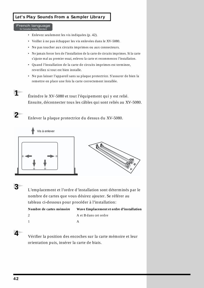
Enlever la pla
fig.T01-002-expF
3
L’emplacemennombre de cartableau ci-des
Nombre de carte
2
1
4
Vérifier la posorientation pu
Vis à enleve
ent les vis indiquées (p. 42).
s échapper les vis enlevées dans le XV-5080.
r aux circuits imprimes ou aux connecteurs.
r lors de l’installation de la carte de circuits imprimes. Si la carte premier essai, enlevez la carte et recommencez l’installation.
lation de la carte de circuits imprimes est terminee, ut est bien installe.
l’appareil sans sa plaque protectrice. S’assurer de bien la ace une fois la carte correctement installée.
-5080 et tout l’équipement qui y est relié. necter tous les câbles qui sont reliés au XV-5080.
que protectrice du dessus du XV-5080.
t et l’ordre d’installation sont déterminés par le tes que vous désirez ajouter. Se référer au
sous pour procéder à l’installation:
s mémoire Wave Emplacement et ordre d’installation
A et B dans cet ordre
A
ition des encoches sur la carte mémoire et leur is, insérer la carte de biais.
A
B
r
Let’s Play Sounds From a Sampler Library
fig.T01-003
5
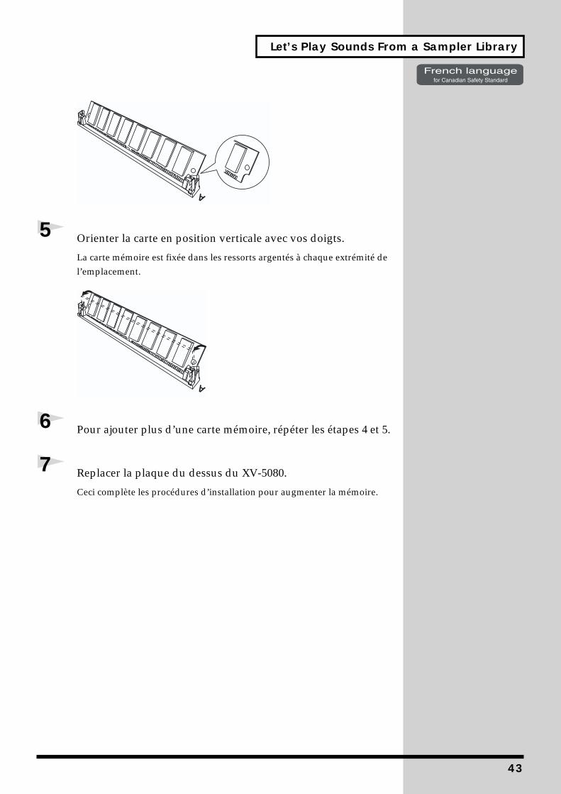
Orienter la car
La carte mémoirel’emplacement.
fig.T01-004
6
Pour ajouter p
7
Replacer la pl
Ceci complète les
te en position verticale avec vos doigts.
est fixée dans les ressorts argentés à chaque extrémité de
lus d’une carte mémoire, répéter les étapes 4 et 5.
aque du dessus du XV-5080.
procédures d’installation pour augmenter la mémoire.
A
A
43
44
Let’s Play Sounds From a Sampler Library
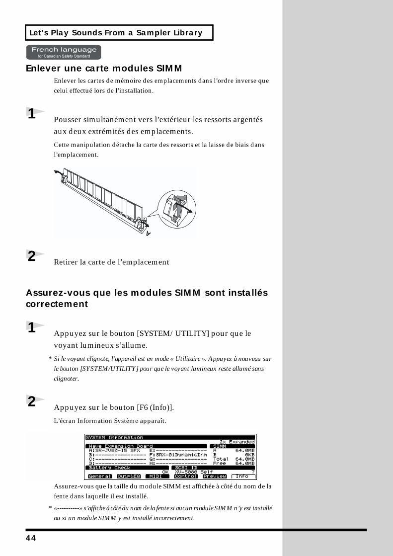
Enlever une cart
Enlever les cartescelui effectué lor
1
Pousser simulaux deux extr
Cette manipulatil’emplacement.
fig.T01-005
2
Retirer la carte
Assurez-vous qucorrectement
1
Appuyez sur voyant lumine
* Si le voyant cligno
le bouton [SYSTE
clignoter.
2
Appuyez sur
L’écran Informat
fig.00-045a.e_80
Assurez-vous qufente dans laque
* «----------» s’affich
ou si un module S
e modules SIMM de mémoire des emplacements dans l’ordre inverse que
s de l’installation.
tanément vers l’extérieur les ressorts argentés émités des emplacements.
on détache la carte des ressorts et la laisse de biais dans
de l’emplacement
e les modules SIMM sont installés
le bouton [SYSTEM/UTILITY] pour que le ux s’allume.
te, l’appareil est en mode « Utilitaire ». Appuyez à nouveau sur
M/UTILITY] pour que le voyant lumineux reste allumé sans
le bouton [F6 (Info)].
ion Système apparaît.
e la taille du module SIMM est affichée à côté du nom de la lle il est installé.
e à côté du nom de la fente si aucun module SIMM n’y est installé
IMM y est installé incorrectement.
A
Let’s Play Sounds From a Sampler Library
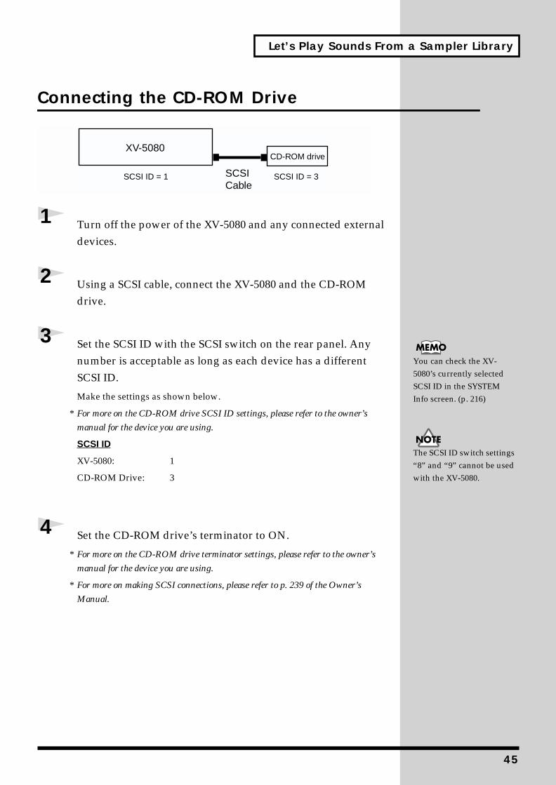
Connecting the CD-ROM Drivefig.00-046.e
1 Turn off the power of the XV-5080 and any connected external devices.
2 Using a SCSI cable, connect the XV-5080 and the CD-ROM drive.
3 Set the SCSI ID with the SCSI switch on the rear panel. Any number is acceptable as long as each device has a different SCSI ID.
Make the settings as shown below.
* For more on the CD-ROM drive SCSI ID settings, please refer to the owner’s
manual for the device you are using.
SCSI ID
XV-5080: 1
CD-ROM Drive: 3
4 Set the CD-ROM drive’s terminator to ON.
* For more on the CD-ROM drive terminator settings, please refer to the owner’s
manual for the device you are using.
* For more on making SCSI connections, please refer to p. 239 of the Owner’s
Manual.
XV-5080CD-ROM drive
SCSICable
SCSI ID = 1 SCSI ID = 3
You can check the XV-5080’s currently selected SCSI ID in the SYSTEM Info screen. (p. 216)
The SCSI ID switch settings “8” and “9” cannot be used with the XV-5080.
45
Let’s Play Sounds From a Sampler Library
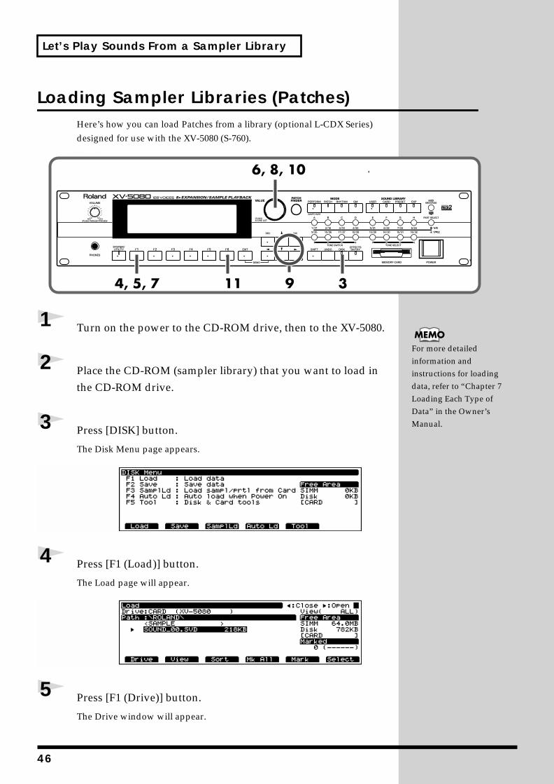
Loading Sampler Libraries (Patches)Here’s how you can load Patches from a library (optional L-CDX Series) designed for use with the XV-5080 (S-760).
fig.00-047.e_80
1 Turn on the power to the CD-ROM drive, then to the XV-5080.
2 Place the CD-ROM (sampler library) that you want to load in the CD-ROM drive.
3 Press [DISK] button.
The Disk Menu page appears.fig.00-048.e_80
4 Press [F1 (Load)] button.
The Load page will appear.fig.00-049.e_80
5 Press [F1 (Drive)] button.
The Drive window will appear.
For more detailed information and instructions for loading data, refer to “Chapter 7 Loading Each Type of Data” in the Owner’s Manual.
46
Let’s Play Sounds From a Sampler Library
6 Turn the VALUE dial to select “SCSI3: (Volume Name).”
7 Press the [F6 (OK)] button.
The CD-ROM’s contents are displayed.
Folders appear within the <> symbols. Folders cannot be load.
The types of folders appearing on the screen may differ according to the library that has been loaded.
8 Turn the VALUE dial or press [ ] or [ ] to select the folder containing the file you want to load.
9 Press [ ] to display the files that can be loaded.
* Press [ ] to move up one level.
10 Turn the VALUE dial or press [ ] or [ ] to select the Patch to be loaded, then press [F5 (Mark)] button to place a “*” marker.
To place a marker on all categories, press [F4 (Mk All)] button. Press this once more to remove all markers.
11 Press the [F6 (Select)] button.
12 Press the [F6 (Load)] button.
The message “Overwrite the following USER data. Sure?” and a window showing the number of the Patch in the User Group that will be overwritten appear in the display.
In this window, you can specify the Patch number to which the Patch is to be loaded.
13 Here, press [F6 (OK)] to overwrite and load.
* To cancel the operation, press the [EXIT] button.
If you want to restore overwritten User Group Patches to the original settings, carry out the Factory Reset procedure (p. 13).
47
Let’s Play Sounds From a Sampler Library
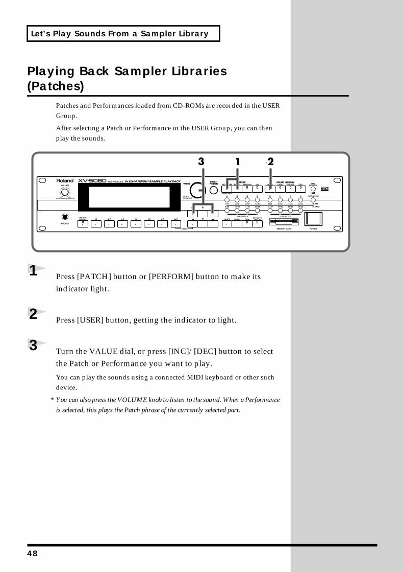
Playing Back Sampler Libraries (Patches)
Patches and Performances loaded from CD-ROMs are recorded in the USER Group.
After selecting a Patch or Performance in the USER Group, you can then play the sounds.
fig.00-050.e_80
1 Press [PATCH] button or [PERFORM] button to make its indicator light.
2 Press [USER] button, getting the indicator to light.
3 Turn the VALUE dial, or press [INC]/[DEC] button to select the Patch or Performance you want to play.
You can play the sounds using a connected MIDI keyboard or other such device.
* You can also press the VOLUME knob to listen to the sound. When a Performance
is selected, this plays the Patch phrase of the currently selected part.
48
Let’s Make a List of Your Favorite Patches
Registering a Patch in the FAVORITE LIST
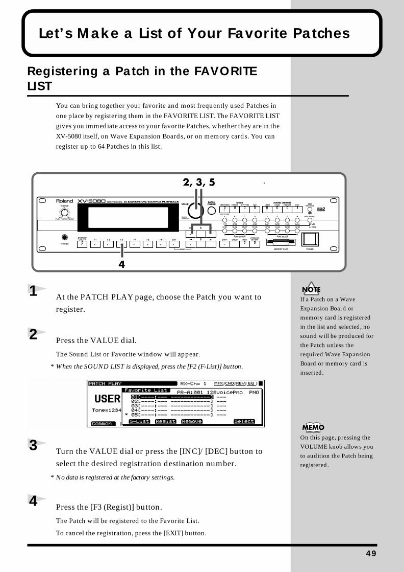
You can bring together your favorite and most frequently used Patches in one place by registering them in the FAVORITE LIST. The FAVORITE LIST gives you immediate access to your favorite Patches, whether they are in the XV-5080 itself, on Wave Expansion Boards, or on memory cards. You can register up to 64 Patches in this list.
fig.00-051.e_80
1 At the PATCH PLAY page, choose the Patch you want to register.
2 Press the VALUE dial.
The Sound List or Favorite window will appear.
* When the SOUND LIST is displayed, press the [F2 (F-List)] button.fig.00-052.e_80
3 Turn the VALUE dial or press the [INC]/[DEC] button to select the desired registration destination number.
* No data is registered at the factory settings.
4 Press the [F3 (Regist)] button.
The Patch will be registered to the Favorite List.
To cancel the registration, press the [EXIT] button.
If a Patch on a Wave Expansion Board or memory card is registered in the list and selected, no sound will be produced for the Patch unless the required Wave Expansion Board or memory card is inserted.
On this page, pressing the VOLUME knob allows you to audition the Patch being registered.
49
Let’s Make a List of Your Favorite Patches
* To cancel the registration, select the file you want to cancel, and then press the [F4
(Remove)] button.
5 Press the [EXIT] button or the VALUE dial to return to the PATCH PLAY page.
You can also register the Rhythm Set in the same way.
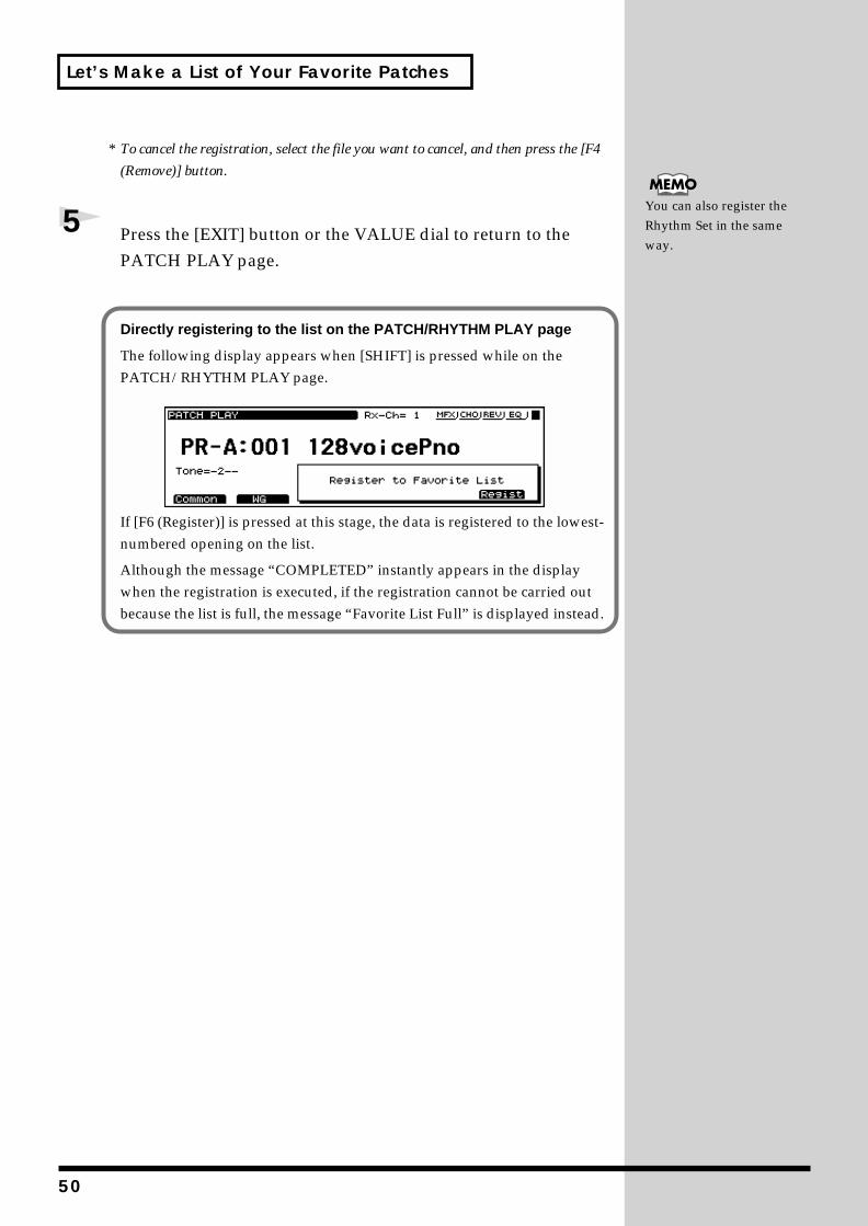
Directly registering to the list on the PATCH/RHYTHM PLAY page
The following display appears when [SHIFT] is pressed while on the PATCH/RHYTHM PLAY page.
fig.00-052a.e_80
If [F6 (Register)] is pressed at this stage, the data is registered to the lowest-numbered opening on the list.
Although the message “COMPLETED” instantly appears in the display when the registration is executed, if the registration cannot be carried out because the list is full, the message “Favorite List Full” is displayed instead.
50
Let’s Make a List of Your Favorite Patches
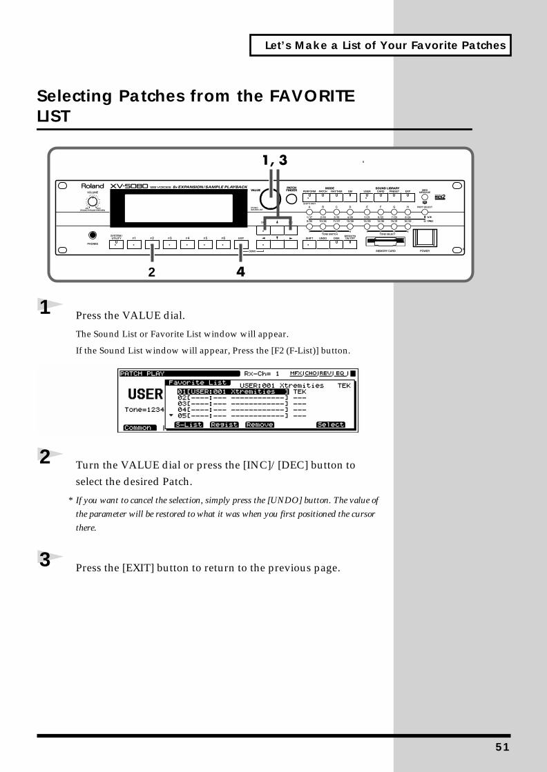
Selecting Patches from the FAVORITE LIST
fig.00-053.e_80
1 Press the VALUE dial.
The Sound List or Favorite List window will appear.
If the Sound List window will appear, Press the [F2 (F-List)] button.fig.00-054.e_80
2 Turn the VALUE dial or press the [INC]/[DEC] button to select the desired Patch.
* If you want to cancel the selection, simply press the [UNDO] button. The value of
the parameter will be restored to what it was when you first positioned the cursor
there.
3 Press the [EXIT] button to return to the previous page.
2
51
5
Using the XV-5080 in Live Performance
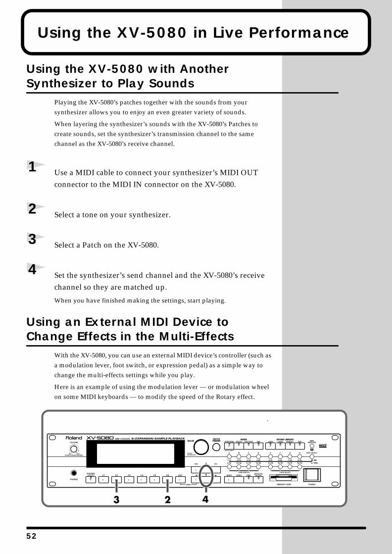
Using the XV-5080 with Another Synthesizer to Play Sounds
Playing the XV-5080’s patches together with the sounds from your synthesizer allows you to enjoy an even greater variety of sounds.
When layering the synthesizer’s sounds with the XV-5080’s Patches to create sounds, set the synthesizer’s transmission channel to the same channel as the XV-5080’s receive channel.
1 Use a MIDI cable to connect your synthesizer’s MIDI OUT connector to the MIDI IN connector on the XV-5080.
2 Select a tone on your synthesizer.
3 Select a Patch on the XV-5080.
4 Set the synthesizer’s send channel and the XV-5080’s receive channel so they are matched up.
When you have finished making the settings, start playing.
Using an External MIDI Device to Change Effects in the Multi-Effects
With the XV-5080, you can use an external MIDI device’s controller (such as a modulation lever, foot switch, or expression pedal) as a simple way to change the multi-effects settings while you play.
Here is an example of using the modulation lever — or modulation wheel on some MIDI keyboards — to modify the speed of the Rotary effect.
fig.00-055.e_80
2
Using the XV-5080 in Live Performance
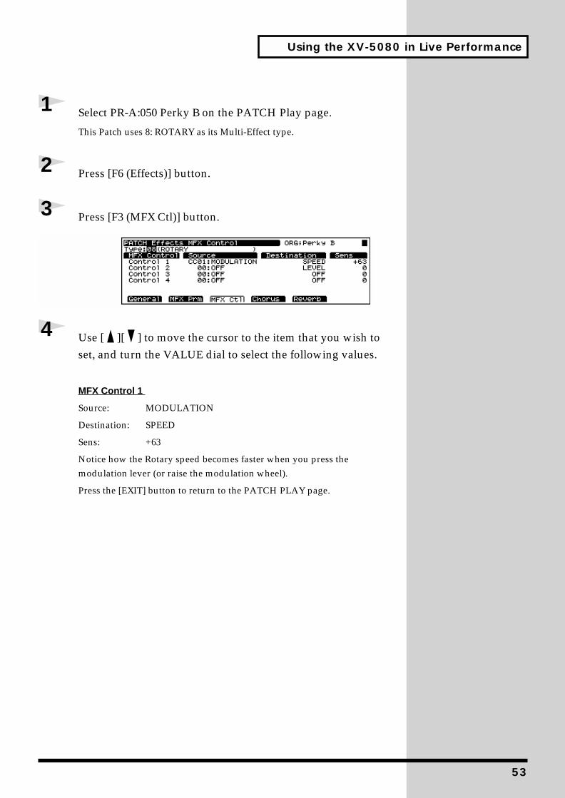
1 Select PR-A:050 Perky B on the PATCH Play page.
This Patch uses 8: ROTARY as its Multi-Effect type.
2 Press [F6 (Effects)] button.
3 Press [F3 (MFX Ctl)] button.fig.00-056.e_80
4 Use [ ][ ] to move the cursor to the item that you wish to set, and turn the VALUE dial to select the following values.
MFX Control 1
Source: MODULATION
Destination: SPEED
Sens: +63
Notice how the Rotary speed becomes faster when you press the modulation lever (or raise the modulation wheel).
Press the [EXIT] button to return to the PATCH PLAY page.
53
5
For More Advanced Use of the XV-5080...
The XV-5080 includes numerous other functions that could not be covered in this volume. Such functions are explained in detail in the Owner’s Manual.
Furthermore, for more advanced ways to use the XV-5080, we recommend reading the Owner’s Manual and referring to the following items.
Editing PatchesFour-Tone Patch (p. 134)
Multi-partial Patch (p. 148)
Editing Tones (p. 134)
Editing Partials (p. 149)
Editing Samples (p. 150)
Creating Performances (p. 159)
Creating Rhythm Sets (p. 168)
Changing effect settings (p. 24)
Setting the output connectors (p. 107)
Using the Digital Interface (p. 119)
Using the XV-5080 as a General MIDI sound module (p. 224)
Saving the data you create (p. 194)
Controlling the XV-5080 in realtime (p. 217)
Changing the Part settings from an external MDI device (p. 221)
Saving on a memory card (p. 195)
4

For More Advanced Use of the XV-5080...
Memo
55
02019823 ’02-6-F2-51K
Demo Song and Profile of the Composer
Epic Passage
Scott Tibbs
©
2000 Roland Corporation
Scott Tibbs has performed and conducted for several orchestral groups, including the Atlanta Symphony Orchestra, throughout the United States, Canada, Latin America, and Japan. His diverse compositional output ranges from numerous film, theater and
television projects to the symphonic concert stage. He has received a Ph.D. degree in composition from UCLA and has recently composed music for recordings with Clare Fisher and Bill Holman. He has performed with well-known artists Dizzy Gillespie, Bill Cosby, Jerry Sienfeld, and Bobby Shew, amongst numerous others.
A Better Day
Igor Len
©
2000 Roland Corporation
Igor Len, pianist and composer, started playing piano at the age of four. He graduated with a Masters Degree in Performing Arts from prestigious Moscow Tchaikovsky Conservatory, and later toured as a pop-keyboardist in Asia, Europe and the United States.
He has appeared in concert with the C. Santana Band, Doobie Brothers, J.Taylor, B.Raitt, T.Dolby, and others. Since relocating to the US, Igor has composed a wide variety of music, ranging from contemporary ballet to dance remixes.
Igor joined Roland Corporation U.S. 1994, and has contributed music and sounds for various Roland products.
Xtra Vaganza
Hans-Joerg Scheffler
©
2000 Digital Audio Design
Born and raised in the Ruhr valley, the biggest industrial area in Germany, Hans's attraction to noise and rhythm came naturally.
Today he runs his own company, DIGITAL AUDIO DESIGN, which produces sampling CDs and CD ROMs.
He works for Roland as a pro audio product specialist, as a sound designer for expansion boards, and as a composer of demo songs. He has released several CDs that use the Roland RSS system.
Soundclips of his work can be downloaded at: http://www.united-sound.com/usmaster/cell2downde.htm
* All rights reserved. Unauthorized use of this material for purposes other than private, personal enjoyment is a violation of
applicable laws.