Embed Size (px)
Citation preview
User Manual
用户手册
YN-E3-RT闪光灯信号发射器

Contents
Introduction . . . . . . . . . . . . . . . . . . . . 1Nomenclature . . . . . . . . . . . . . . . . . . . 2-4
Preparation Before Use . . . . . . . . . . . . . . . 5-6
Wireless Flash Shooting. . . . . . . . . . . . . . . . 7Wireless Settings . . . . . . . . . . . . . . . . . 8-9
ETTL:Fully Automatic Wireless Flash Shooting . . . . . 10-14
M: Wireless Multiple Flash Shooting with Manual Flash Output. 15-16
MULI: Stroboscopic Flash . . . . . . . . . . . . . . 17
Gr: Shooting with a Different Flash Mode for Each Group . 18-19
Remote Release from a Slave Unit/Linked Shooting . . . 20-21
Transmitter Control from Camera’s Menu Screen . . . . 22-23C.Fn/P.Fn: Setting . . 24-27Reference . . . . . . . . . . . . . . . . . . . 28-29Troubleshooting Guide . . . . . . . . . . . . . . 30-31Specifications . . . . . . . . . . . . . . . . . . 32-33
Read this instruction manual while also referring to the instruction manuals of your camera and Speedlite.
Before using the transmitter, read this instruction manual and the instruction manuals of your camera and Speedlite to familiarize yourself with the operations.
Custom and Personal Functions
Introduction
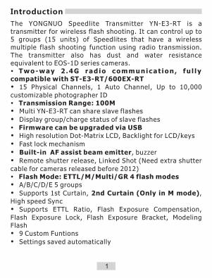
The YONGNUO Speedlite Transmitter YN-E3-RT is a transmitter for wireless flash shooting. It can control up to 5 groups (15 units) of Speedlites that have a wireless multiple flash shooting function using radio transmission. The transmitter also has dust and water resistance equivalent to EOS-1D series cameras.�Two-way 2 .4G rad io communicat ion , fu l l y compatible with ST-E3-RT/600EX-RT�15 Physical Channels, 1 Auto Channel, Up to 10,000 customizable photographer ID�Transmission Range: 100M�Multi YN-E3-RT can share slave flashes
�Display group/charge status of slave flashes�Firmware can be upgraded via USB�High resolution Dot-Matrix LCD, Backlight for LCD/keys
�Fast lock mechanism
�Built-in AF assist beam emitter, buzzer
�Remote shutter release, Linked Shot (Need extra shutter cable for cameras released before 2012)�Flash Mode: ETTL/M/Multi/GR 4 flash modes�A/B/C/D/E 5 groups
�Supports 1st Curtain, 2nd Curtain (Only in M mode), High speed Sync�Supports ETTL Ratio, Flash Exposure Compensation, Flash Exposure Lock, Flash Exposure Bracket, Modeling Flash�9 Custom Funtions
�Settings saved automatically
1
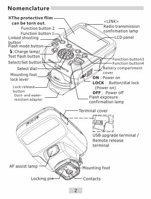
※The protective flim
can be torn out.
LCD panelFunction button 1
Linked shooting button
Select/Set button
Select dial
Dust- and water-
resistant adapter
Mounting footlock lever
Lock-release
button
ON:Power on
LOCK: Button/dial lock
(Power on)
OFF: Power offFlash exposure confirmation lamp
Battery compartment
cover
<LINK>
Radio transmission confirmation lamp
Terminal cover
Mounting foot
Locking pin Contacts
USB upgrade /
Remote release terminal
terminal
AF assist lamp
:Charge lamp/ Test flash button
Function button 2
Function button4Function button3
Flash mode button
2
Nomenclature

Manual flashM:Manual Flash
Manual flash
output
E-TTL(II) Autoflash
FEB
FEC amount
ETTL:E-TTL II/E-TTL autoflash
Flash exposure
compensation(FEC)
Firing group
Flash ratio
Flash exposure level Slave flash ready
Custom
Functions
Ch:Channel
AUTO: Channel
automatic setting
Radio transmission
wireless shooting
Beep
Personal Functions
High-speed sync
Master
FEB sequence
RATIO:Flash ratio
�The display will show only the settings currently applied.�The functions displayed above function buttons 1 to 4, change according to the setting’s status.
�When a button or dial is operated, the LCD panel illuminates.
Manual Flash 2nd
curtain sync
3
Nomenclature
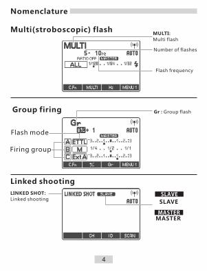
Multi(stroboscopic) flash
Group firing
Linked shooting
MULTI:
Multi flash
Number of flashes
Flash frequency
Gr : Group flash
Flash mode
Firing group
LINKED SHOT:
Linked shootingSLAVE
MASTER
SLAVE
MASTER
4
Nomenclature
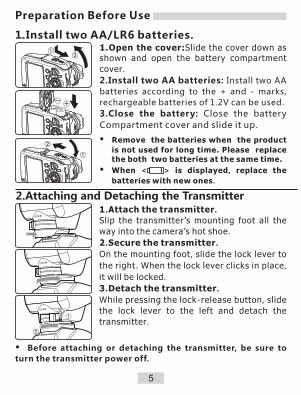
1.Install two AA/LR6 batteries.1.Open the cover:Slide the cover down as shown and open the battery compartment
cover.
2.Install two AA batteries: Install two AA
batteries according to the + and - marks,
rechargeable batteries of 1.2V can be used.
3.Close the battery: Close the battery
Compartment cover and slide it up.
�Remove the batteries when the product
is not used for long time. Please replace the both two batteries at the same time.
�When < > is displayed, replace the
batteries with new ones.
Preparation Before Use
5
2.Attaching and Detaching the Transmitter1.Attach the transmitter.
Slip the transmitter’s mounting foot all the
way into the camera’s hot shoe.
2.Secure the transmitter.
On the mounting foot, slide the lock lever to
the right. When the lock lever clicks in place,
it will be locked.
3.Detach the transmitter.
While pressing the lock-release button, slide
the lock lever to the left and detach the
transmitter.
�Before attaching or detaching the transmitter, be sure to
turn the transmitter power off.
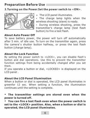
ØThe LCD panel illuminates.
�The charge lamp lights when the
wireless shooting (slave) is ready.
�During wireless shooting, press the transmitter’s charge lamp (test flash button) to fire a test flash.
About Auto Power OffTo save battery power, the power will turn off automatically after 5 min. of idle use. To turn on the transmitter again, press the camera’ s shutter button halfway, or press the test flash button (charge lamp).
About the Lock FunctionBy setting the power switch to <LOCK>, you can disable flash’ s button and dial operations. Use this to prevent the transmitter function settings from being accidentally changed after you set them.
If you operate a button or dial, <LOCKED> is displayed on the LCD panel .
About the LCD Panel IlluminationWhen a button or dial is operated, the LCD panel illuminates in greenfor 12 sec. When setting a function, the illumination continues until the setting is complete.
�The transmitter settings are stored even when the
power is turned off.
�You can fire a test flash even when the power switch is
set to the <LOCK> position. Also, when a button or dial is operated, the LCD panel illuminates.
3.Turning on the Power:Set the power switch to <ON>.
Preparation Before Use
6

C
AB
MASTER
SLAVE
SLAVE
SLAVE
Positioning and Operation Range(Example of wireless flash shooting)
Transmission distance
Approx. 100 m
Using a transmitter and a Speedlite compatible with radio transmission wireless shooting makes it easy to shoot with
advanced wireless multiple flash lighting, in the same way as
normal E-TTL II/E-TTL autoflash shooting.
The system is designed so that the settings of the transmitter
attached to the camera (master) are automatically reflected on
the Speedlite that is wirelessly controlled (slave). Therefore, you
do not need to operate the slave unit while shooting.
The basic relative positions and operating range are as shown in
the figure. You can then perform wireless E-TTL II/E-TTL
autoflash shooting just by setting the master unit to <ETTL>.
Wireless Flash Shooting
�Before shooting, perform a test flash (p.10) and test
shooting.
�The transmission distance may be shorter depending
on the conditions such as the positioning of slave units,
the surrounding environment and weather conditions.
7

Wireless Settings
1.Display < >.�Press function button 4 to
displaym < >.
2.Set a channel.
�Press function button 1 <CH>.
�Turn < > to select “AUTO”
or a channel from Ch. 1 to 15, and
press the < > button.
3.Set a wireless radio ID.
�Press function button 2 < >.
�Tu rn < > t o s e l e c t t h e
position(digit) or number to set,
and press the < > button.
�Press function button 4 < > to
return to the shooting-ready state.
ØWhen transmission between the master unit and slave unit is
established, the <LINK> lamp is lit
in green.(Refer to page 28)
To avoid interference, Set the same channel and ID
for both the master unit and slave unit.
Set a flash that is compatible with radio transmission wireless flash shooting as the slave unit. For the slave unit settings, see the flash’s instruction manual.
ID
8
Setting the Master Unit Transmission Channel /
Wireless Radio ID.

Scanning while “AUTO” is set
Scanning while Ch. 1 to 15 is set
�Scanning the Master Unit Transmission Channels to Set
You can scan the radio reception status and set the master unit’s transmission channel automatically or manually. When the channel is set to “AUTO”, the channel with the best reception signal is automatically set. When setting the channel manually, you can set the transmission channel again while referring to the scan results.
Wireless Settings
Run the scan.
�Press function button 4 to display
< >.
�Press function button 3 < >.
ØThe channel is reset to one with a
good reception signal.
2.Set a channel.�Turn< >to select a channel from Ch1 to 15.
�Press the < > button to set
the channel and return to the shooting ready state.
1.Run the scan.
�Press function button 4 to display
< >.
�Press function button 3 < >.
�The r a d i o r e c ep t i o n s t a t u s i s
displayed in a graph.
� The higher the peak of the channel in
the graph, the better the radio reception
signal.
9

ETTL:Fully Automatic Wireless Flash Shooting
1.Set the flash as the slave unit A, B or C . The flash will not fire if it is set to D or E.
2.Set the same channel and ID of the master unit and slave unit .(p.8)
3.Position the camera and the flash.(p.7)
4.Press the <MODE> button on the master unit and set the flash mode to <ETTL>.
�The slave unit is set automatically to <ETTL> during shooting via the control from the master unit.
5.Check the transmission status and that the flash is ready.
�Check that the <LINK> lamp is lit in green.
�Check that the < > slave flash-ready icon is lit on the master unit’s LCD panel.
�When the recycling of all the flash units is completed, the master unit's charge lamp lights.
6.Check the operation.
�Press the master unit’s test flash button (charge lamp). The slave unit flashes.
7.Take the picture.
�If a standard flash exposure was o b t a i n e d , t h e f l a s h e x p o s u r e confirmation lamp lights for 3 sec.
10
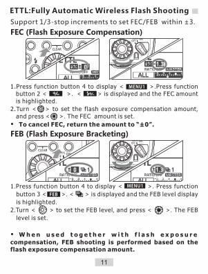
FEC (Flash Exposure Compensation)
FEB (Flash Exposure Bracketing)
1.Press function button 4 to display < >.Press function button 2 < >. < > is displayed and the FEC amount is highlighted.
2.Turn < > to set the flash exposure compensation amount, and press < >. The FEC amount is set.
�To cancel FEC, return the amount to “±0”.
Support 1/3-stop increments to set FEC/FEB within ±3.
1.Press function button 4 to display < >. Press function
button 3 < >. < > is displayed and the FEB level display
is highlighted.
2.Turn < > to set the FEB level, and press < >. The FEB
level is set.
�W h e n u s e d t o g e t h e r w i t h f l a s h e x p o s u r e
compensation, FEB shooting is performed based on the flash exposure compensation amount.
ETTL:Fully Automatic Wireless Flash Shooting
11
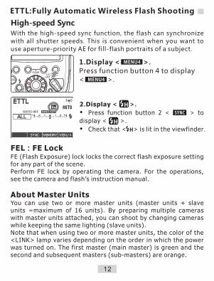
High-speed Sync
With the high-speed sync function, the flash can synchronize
with all shutter speeds. This is convenient when you want to
use aperture-priority AE for fill-flash portraits of a subject.
1.Display < >.
Press function button 4 to display
< >.
2.Display < >.
�Press function button 2 < > to
display < >.
�Check that < > is lit in the viewfinder.
FEL:FE LockFE (Flash Exposure) lock locks the correct flash exposure setting for any part of the scene.Perform FE lock by operating the camera. For the operations, see the camera and flash’s instruction manual.
About Master UnitsYou can use two or more master units (master units + slave units =maximum of 16 units). By preparing multiple cameras with master units attached, you can shoot by changing cameras while keeping the same lighting (slave units).Note that when using two or more master units, the color of the <LINK> lamp varies depending on the order in which the power was turned on. The first master (main master) is green and the second and subsequent masters (sub-masters) are orange.
12
ETTL:Fully Automatic Wireless Flash Shooting
C
A B
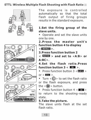
T h e e x p o s u r e i s c o n t r o l l e d automatically so that the total f lash output of f i r ing groups results in the standard exposure.
1.Set the firing group of the
slave units.�Operate and set the slave units one by one.2.Press the master un i t ’s function button 4 to display
< >.
3.Press function button 2
< > and set to <A:B> or
A:BC>.
4 .Set the f lash ratio.Press
function button 3 < >.
�Press function button 3 < >
or < >.
�Turn < > to set the flash ratio
or the flash exposure, and press
the < > button.
�Press function button 4 < >
to return to the shooting-ready
state.
5.Take the picture.The slave units flash at the set flash ratio.
ETTL: Wireless Multiple Flash Shooting with Flash Ratio
A:B /+ -
/+ -C
13

Slave Group Control
Firing group A
If you need more flash output or wish
to perform more sophisticated lighting,
you can increase the number of slave
units.
Simply set an additional slave unit to
the firing group (A, B or C) whose flash
output you want to increase. You can
increase the number of slave units up
to 15 units in total.For example, if you set a firing group with three slave units to
<A>,the three units are controlled as a single firing group A with
a large flash output.
�To fire the three firing groups A, B and C at the same time, set
<A:B:C>. With the < A:B > setting, firing group C does not fire.
� If you shoot with firing group C pointing directly toward the
main subject, overexposure may result.
�The flash ratio of 8:1 to 1:1 to 1:8 is equivalent to 3:1 to 1:1 to
1:3 (1/2-stop increments) when converted to number of stops.
� The details of the flash ratio settings are as follows.
14
Modeling FlashModeling Flash from a Master Unit
�Press the depth-of-field preview
�button on the camera.
� The flash fires continuously for 1
sec.
ETTL: Wireless Multiple Flash Shooting with Flash Ratio

M: Wireless Multiple Flash Shooting with Manual Flash Output
1.Set the flash mode to <M>.2.Set the number of firing groups.
�While < > is displayed, press
function button 2 < > and set
the groups to fire.
�The setting changes as follows
each time you press the button:
ALL(RATIO OFF)→
A/B(RATIO A:B)→
A/B/C(RATIO A:B:C)
3.Select a firing group.
�Press function button 3< >,
�turn < > and select the group for
which you want to set the flash output.
4.Set the flash output.
�Press function button3< >.
�Turn < > to set the flash output,
and press the < > button.
�Repeat steps 3 and 4 to set the flash output of all groups.
5.Take the picture.
�Each group fires at the set flash output.
This describes wireless (multiple flash) shooting using manual flash.You can shoot with a different flash output setting for each slave unit(firing group). Set all parameters on the master unit.
/+ -
15
�When ALL <RATIO OFF> is set, set A, B or C as the firing group for the slave units. The flash will not fire if it is set to D or E.�To fire multiple slave units with the same flash output, select ALL <RATIO OFF> in step 2.

M:The shutter sync of manual flash setting
1.Display < >.
Press funct ion button 4 to
display< >.
2.Shutter Sync setting
While < > is displayed, press
function button 2 < > and set
the shutter sync.
�The setting changes as follows
each time you press the button:
:High-speed Sync
:2nd Curtain Sync
(no icon):1st Curtain Sync
You can use 1st curtain Sync, high-speed Sync, or 2nd
curtain sync in manual flash.
16
�The 2nd curtain sync can be
used in manual flash only.
�When using the 2nd curtain
sync , wireless settings and
other parameters recommend
using the speedlite transmitter
settings.
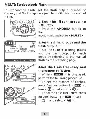
MULTI: Stroboscopic Flash
In stroboscopic flash, set the flash output, number of flashes, and flash frequency (number of flashes per second = Hz).
1 . S e t t h e f l a s h m o d e t o
<MULTI>.�Press the <MODE> button on themaster unit and set to <MULTI>.
2.Set the firing groups and the
flash output.
�Set the number of firing groups and the flash output for each group by referring to the manual flash on the preceding page.
3.Set the flash frequency and
thenumber of flashes.
�While < > is displayed,
perform the following procedure.
�To set the number of flashes,
press function button 2 < >,
turn < > and select < >.
�To set the flash frequency, press
function button 3 < >, turn
< > and select < >.
17

Gr: Shooting with a Different Flash Mode for Each Group
A BC
ED
Ext.A
E-TTL II
�Yo u c a n s h o o t w i t h a different flash mode set for each firing group, with up to 5groups (A/B/C/D/E).�The flash modes that can be
s e t a r e E - T T L I I / E - T T L
autoflash, Manual flash and
Auto external flash metering.
�This function is for advanced u s e r s w h o a r e v e r y knowledgeable and experienced in lighting.
�When using the <Gr> flash mode of the camera released from 2007 to 2011, all the parameters should be set up through the speedlite transmitter.
1.Set the flash mode to <Gr>.
�Press the <mode> button on
the master unit and set the flash
mode to<Gr>.
2.Set the firing group on the
slave units.
�Operate and set the slave
units one by one.
�Set a firing group (A/B/C/D/E)
for all the slave units.
18
* The flash mode settings are indicated only as an example.
Manual Flash
Manual Flash
Manual Flash

3.Set the flash mode of each firing
group by operating the master unit.
�While < > is displayed, press
function button 3 < > and turn
< > to select the group.
�Press function button 2 < >
and select the flash mode of the
selected group from < E-TTL>、< M
> and <Ext.A >.
�To turn the firing of the selected
group off, press function button 1
< > to set it to <OFF>.
4.Set the flash output or flash
exposure compensation amount.
�While a firing group is selected,
press function button 3 < >.
�Turn < > to set the flash function
corresponding to the flash mode, and
press < >.
�When using the <M> mode, set
the flash output. When using the < E-TTL> or <Ext.A> mode, set the flash
exposure compensation amount as
required.
�If you press function button 2
< > when < > is displayed,
flash exposure compensation can be
set for all the firing groups.
Gr: Shooting with a Different Flash Mode for Each Group
19
You can perform remote release (remote control shooting) from a flash set as a slave unit. (see the flash’s instruction manual).
*When using the function with the cameras released until
2011, it needs the shutter release cable LS-MINIB/C3 or
LS-MINIB/C1(sold separately). As for the EOS digital
cameras(such as EOS-1D X) released after 2012, it does
not need the shutter release cable.
Remote Release from a Slave Unit/Linked Shooting
Remote Release from a Slave Unit*
20
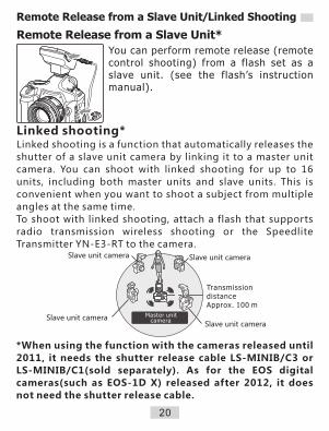
Linked shooting*Linked shooting is a function that automatically releases the
shutter of a slave unit camera by linking it to a master unit
camera. You can shoot with linked shooting for up to 16
units, including both master units and slave units. This is
convenient when you want to shoot a subject from multiple
angles at the same time.
To shoot with linked shooting, attach a flash that supports
radio transmission wireless shooting or the Speedlite
Transmitter YN-E3-RT to the camera.
Slave unit camera
TransmissiondistanceApprox. 100 m
Slave unit cameraSlave unit camera
Slave unit camera
Master unit camera
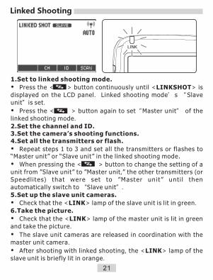
1.Set to linked shooting mode.
�Press the < > button continuously until <LINKSHOT> is displayed on the LCD panel. Linked shooting mode’ s “Slave unit”is set.
�Press the < > button again to set“Master unit” of the linked shooting mode.
2.Set the channel and ID.3.Set the camera’s shooting functions.4.Set all the transmitters or flash.
�Repeat steps 1 to 3 and set all the transmitters or flashes to “Master unit” or “Slave unit” in the linked shooting mode.
�When pressing the < > button to change the setting of a unit from ”Slave unit” to ”Master unit,” the other transmitters (or Speedl i tes ) that were set to ”Master unit” unti l then automatically switch to “Slave unit”.
5.Set up the slave unit cameras.
�Check that the <LINK> lamp of the slave unit is lit in green.
6.Take the picture.
�Check that the <LINK> lamp of the master unit is lit in green and take the picture.
�The slave unit cameras are released in coordination with the master unit camera.
�After shooting with linked shooting, the <LINK> lamp of the slave unit is briefly lit in orange.
Linked Shooting
21

Transmitter Control from Camera’s Menu Screen
When using EOS digital cameras released since 2007, you can set flash functions, transmitter functions or Custom Functions from the camera’s menu screen. See the camera’s instruction manual.
1.Select [External Speedl ite
control].
�Select [External Speedlite control]
or [Flash control].
2.Select [Flash function settings].
�Select [Flash function settings] or
[External flash func. setting].
�The s c reen changes t o t he
(external) flash function settings
screen.
3.Set the function.
�T h e s e t t i n g s c r e e n v a r i e s
depending on the camera.
�Se lec t an i t em and se t the
Settings Available in [Flash function settings]
EOS digital cameras released since 2012 When using the transmitter with cameras such as EOS-1D X, you can set the functions for “Radio transmission wireless shooting” in the [Flash function settings] screen.
EOS digital cameras released from 2007 to 2011When performing “ Radio transmission wireless shooting”, set the functions by operating the transmitter.
22
s menu screen. camera
s instruction manual. For the camera operations, see the camera

E-TTL II flash meteringFor normal exposures, set it to [Evaluative]. If [Average] is set,
the flash exposure will be averaged for the entire scene
metered by the camera. Flash exposure compensation may be
necessary depending on the scene. This setting is for
advanced users.Flash synchronization speed in Av modeYou can set the flash sync speed when performing wireless
flash shooting in aperture-priority AE (AV) mode.Flash modeYou can select the flash mode from [E-TTL II], [Manual flash],[MULTI flash] and [Individual group control] to suit your
desired flash shooting.Shutter synchronizationYou can select the flash firing timing/method from [1st
curtain] and [High-speed synchronization]. To perform
normal wireless flash shooting, set it to [1st curtain].Flash exposure compensationIn the same way as normal exposure compensation, you can
set exposure compensation for flash. The flash exposure
compensation amount can be set up to ±3 stops in 1/3-stop
increments.FEBYou can take three shots while automatically changing the
flashoutput. The settable range is up to ±3 stops in 1/3-stop
increments.Wireless flash functions (setting)R a d i o t r a n s m i s s i o n w i re l e s s f l a s h s h o o t i n g i s s e t
automatically.Clear Speedlite (function) settingsYou can return the transmitter settings to their default
settings.
23
Transmitter Control from Camera’s Menu Screen

C.Fn/P.Fn: Setting Custom and Personal Functions
24
You can customize the transmitter features to suit your shooting preferences with Custom Functions and Personal Functions.
1.Display the Custom Functions
screen.
�Short press function button 1
< >The Custom Functions screen is
displayed.
�Long press function button 1
< >The Personal Functions
screen is displayed.
2.Select an item to set.
�Turn < > to select an item(number)
to set.
3.Change the setting.
� Press the < > button, The setting
is displayed. Turn < > to select the
setting that you want, and press the
< > button.
�Press function button 4 < > to
return to the shooting-ready state.
�
For the Custom Functions, see pages 26 to 27.
If C.Fn-20 and 22 are not displayed, set them by operating the
transmitter.
1.Select [Flash C.Fn settings] or
[External flash C.Fn setting].
2 .Select the Custom Function
number and set the function.
�The displayed contents vary
depending on the camera.
Transmitter C.Fn Settings From Camera’s Menu Screen

25
P.Fn-21: Legacy Trigger (Single-contact trigger function)
P.Fn-22: Free Mask Group(Quickly set background flash groups)
With this function, this YN-E3-RT is
more compatible with non-Canon
cameras trigger with its single contact
on the hot shoe. Only“M”mode
supported.
0:ON (Enabled)
1:OFF (Disabled)�Only when the non-Canon cameras work abnormally with
legacy trigger function, set P.Fn-21 as “ON”; when use a
Canon camera, please set P.Fn-21 as “OFF”.
�Press TEST button to test the flash every time the flash
output is adjusted manually.
For example: set as 0:D/E from P.FN22 Free Mask Group,
in Gr mode, long press < > button, the display
screen shows “FM”, at this moment, only D/E group at
the receiving group responds and flashes, A/B/C won't
flash. This function is suitable for quickly controlling
the background flash groups when shooting. Long
press < > again to return to normal.
Quickly enable/disable the flash group
which is used as background flash in Gr
mode.
0: D/E (quickly enable D/E group)
1: C/D/E (quickly enable C/D/E group)
2: B/C/D/E (quickly enable B/C/D/E
group)
�The above functions correspond to the firmware program
since V1.19.
FM
P.Fn: Setting Personal Functions

0: (Enabled (Depth-of-field preview button))
Press the camera’s depth-of-field preview button to fire the
modeling flash.
1: (Enabled (Test firing button))
Press the transmitter’s test flash button to fire the modeling flash.
2: / (Enabled (with both buttons))
Press the camera’s depth-of-field preview button or the
transmitter’s test flash button to fire the modeling flash.
3: OFF (Disabled)
Disables the modeling flash.
When the transmitter is not operated for 5 min., the power turns
off automatically to save energy. You can disable this function.
0: ON (Enabled)
1: OFF (Disabled)
You can set whether or not to cancel FEB automatically after
shooting three shots with FEB.
0: ON (Enabled)
1: OFF (Disabled)
You can change the order of the FEB sequence, 0: Standard
exposure, – :Decreased exposure (darker) and +: Increased
exposure (brighter).
0: 0 → → +
1: - → 0 → +
-
(Auto power off)C.Fn-01:
C.Fn-02: (Modeling flash)
C.Fn-03: (FEB auto cancel)
(FEB sequence)C.Fn-04:
C.Fn: Setting Custom Functions
26

You can change the flash output when firing the test flash in
E-TTL II/E-TTL autoflash mode.
0: 1/32 (1/32)
1: 1/1 (Full output)
C.Fn-07: (Test firing with autoflash)
C.Fn-08: (AF-assist beam firing)
0: ON (Enabled)
1: OFF(Disabled)The AF-assist beam is not fired from
the speedlite transmitter
C.Fn-13: (Flash exposure metering setting)
0: + (Speedlite button and dial)
1: (Speedlite dial only)
You can perform flash exposure compensation by directly
turning < >, without pressing the < > button.
C.Fn-20: (Beep)
You can enable a beep to sound when the slave units are
fully charged.
0: OFF (Disabled)
1: ON (Enabled)
C.Fn-22: (LCD panel illumination)
When a button or dial is operated, the LCD panel illuminates.
You can change this illumination setting.
0: 12sec (On for 12 sec.)
1: OFF (Disable panel illumination)
2: ON (Illumination always on)
C.Fn: Setting Custom Functions
27

Reference
28
About the <LINK> LampThe color of the <LINK> lamp changes depending on the transmission status of the master unit and the slave unit.
�If the transmission channels of the master unit and slave unit are
�different, the slave unit does not fire. Set both to the same number, or set both to ”AUTO”.
Color Status Description Action
Green LitTransmission
OK –
Lit Not connected Check the channel and ID
Too many units Master units + slave units =
16 units or less
Error Turn the power off and on again
BlinkingRed
Clearing Transmitter Settings
Press function buttons 2 and 3 simultaneously for 2 seconds or longer. The transmitter settings are cleared and the shooting mode
returns to <ETTL> flash mode.
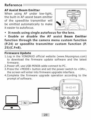
�It needs using single autofocus for the lens.
�Enable or disable the AF assist Beam Emitter
function through the camera menu custom function
(P.24) or speedlite transmitter custom function (P.
25)(C.Fn8).
AF Assist Beam EmitterWhen using AF under low-light, the built-in AF-assist beam emitter
of the speedlite transmitter will
be emitted automatically to make
it easier to autofocus.
29
Reference
Firmware Update1.Log in the YONGNUO official website (www.hkyongnuo.com)
to download the firmware update software and the latest firmware.
2.Power off, use USB-MINIB cable connect to PC. 3.Press the <MODE> button and set the power switch to <ON>,
the screen will enter into firmware upgrade interface.4.Complete the firmware upgrade operation according to the
prompt of software.

Troubleshooting Guide
Power does not turn on.�Make sure that the batteries are installed in the correct
orientation.�Insert the mounting foot into the camera’s hot shoe all the
way, slide the lock lever to the right, and secure the transmitter
to the camera .�If the electrical contacts of the transmitter and camera are
dirty, clean the contacts.�The charge lamp lights when the wireless shooting (slave) is
ready.
The power turns off by itself.�The transmitter’ s auto power off function has activated.
Press the shutter button halfway, or press the test flash button .
The slave unit does not fire.�Check that the slave unit supports radio transmission wireless
flash shooting.�Set the slave unit to < > < >.�Set the transmission channels and wireless radio IDs of the
master unit and slave unit to the same numbers.�Check that the slave unit is within the transmission range of
the master unit.
Unable to use the AF assist beam emitter.�Check the custom function C.Fn08.
Firmware update failed or the screen display the
firmware upgrade interface all along.�Disconnect, restart the equipment and try again.
The screen displays "ERROR: 2001"� Try upgrade the firmware again.
30

The picture is underexposed or overexposed.
�If there was a highly reflective object (glass window, etc.) in
the picture, use FE lock).
�If the subject looks very dark or very bright, set flash
exposure compensation.
�When high-speed sync is set, the effective flash range is
shorter.
Position the slave unit closer to the subject.
�When using autoflash shooting with three firing groups A, B
and C, do not fire with firing group C pointed toward the main
subject.
�When shooting with a different flash mode setting for each
firing group, do not fire with multiple firing groups set to
<ETTL> or <Ext.A> pointed toward the main subject .
The picture is very blurred.
� When the shooting mode is set to <AV> and the scene is
dark, slow sync is enabled automatically (the shutter speed
becomes slower). Use a tripod, or set the shooting mode to <P>
or fully automatic mode. Note that you can also set the sync
speed in [Flash sync. speed in Av mode]
Cannot release from a slave unit.
� When an EOS camera which was released up to 2011, has
remote control terminal and is compatible with E-TTL II/E-TTL
autoflash is used to perform remote release from a slave unit or
when it has been set as the slave unit during linked shooting, the
shutter release cable “ LS-MINIB/C3 “ or “ LS-MINIB/C1 ”
(sold separately) is necessary.
31
Troubleshooting Guide

Type: On-camera Speedlite transmitterCompatible cameras: EOS type-A camera compatible with
E-TTL II/E-TTL autoflash Exposure control system: E-TTL II/E-TTL autoflash, manual
f l a sh , s t roboscop i c f l a sh , au to external flash metering**Only when the flash mode is set to <Gr>
Frequency: 2405 - 2475 MHZModulation system: P r i m a r y m o d u l a t i o n : O Q P S K ,
secondary modulation: DS-SSChannel: Auto, Ch. 1 - 15Wireless radio ID: 0000 - 9999Slave unit control: Up to 5 groups (A/B/C/D/E), up to 15
unitsTransmission distance: Approx. 100 m Flash ratio control: 1:8 - 1:1 - 8:1, 1/2-stop increments
Flash exposurecompensation: ±3 stops in 1/3- incrementsFEB: ±3 stops in 1/3- increments (when
u s e d w i t h f l a s h e x p o s u r e compensation)
FE lock: Press the camera’s <M-Fn>, <FEL> or <*> button
High-speed sync: ProvidedManual flash: 1 / 1 - 1 / 1 2 8 p o w e r ( 1 / 3 - s t o p
increments)Stroboscopic flash: Provided (1 - 500 Hz)
32
Specifications

33
Specifications
Slave flash battery check: On the master unit’s LCD panel, the < > icon lights, the slave unit’s AF-assist beam emitter bl inks and the charge lamp lights.
Flash exposure confirmation: F lash exposure conf i rmat ion lamp lights
Modeling flash: Fired with camera‘s depth-of-field preview button
Linked shooting: ProvidedCustom Functions: 9
AF assist Beam Emitter: Provided
Firmware update : Provided
Power source: 2 AA/LR6 alkaline batteries Ni-MH batteries
Wireless flash shooting Approx. time:1 0 c o n t i n u o u s hours*
time *When using AA/LR6 alkaline batteries
Power saving: Power off after 5 min. of idle operation
Dimensions: Approx. 67.7 (W) x 66.7 (H) x 81.3 (D) mm
Weight: Approx. 110 g (transmitter only, excluding batteries)
The functions of this user manual are based on test conditions of our company.Further notice will not be given if the design and specifications change.The YONGNUO logo in this manual includes the registered trademark or trademark of Shenzhen Yongnuo Photography E q u i p m e n t C o . , L t d i n C h i n a o r / a n d o t h e r countries(regions).All other trademarks are the property of their respective owners.