Embed Size (px)
Citation preview
COSTRUZIONE APPARECCHIATURE ELETTRONICHE - OLEODINAMICHE - INDUSTRIALICOSTRUZIONE APPARECCHIATURE ELETTRONICHE - OLEODINAMICHE - INDUSTRIALICOSTRUZIONE APPARECCHIATURE ELETTRONICHE - OLEODINAMICHE - INDUSTRIALICOSTRUZIONE APPARECCHIATURE ELETTRONICHE - OLEODINAMICHE - INDUSTRIALICOSTRUZIONE APPARECCHIATURE ELETTRONICHE - OLEODINAMICHE - INDUSTRIALI
42028 - POVIGLIO - (R.E.) - Via Parma, 59 - ITALIATel. (0522) 960050 (r.a.) - Tlx. 530021 AINDRE I - Fax (0522) 960259
ZAPIMOS H0 200A
OPERATING HANDBOOK AND
FUNCTION DESCRIPTION
Page 1
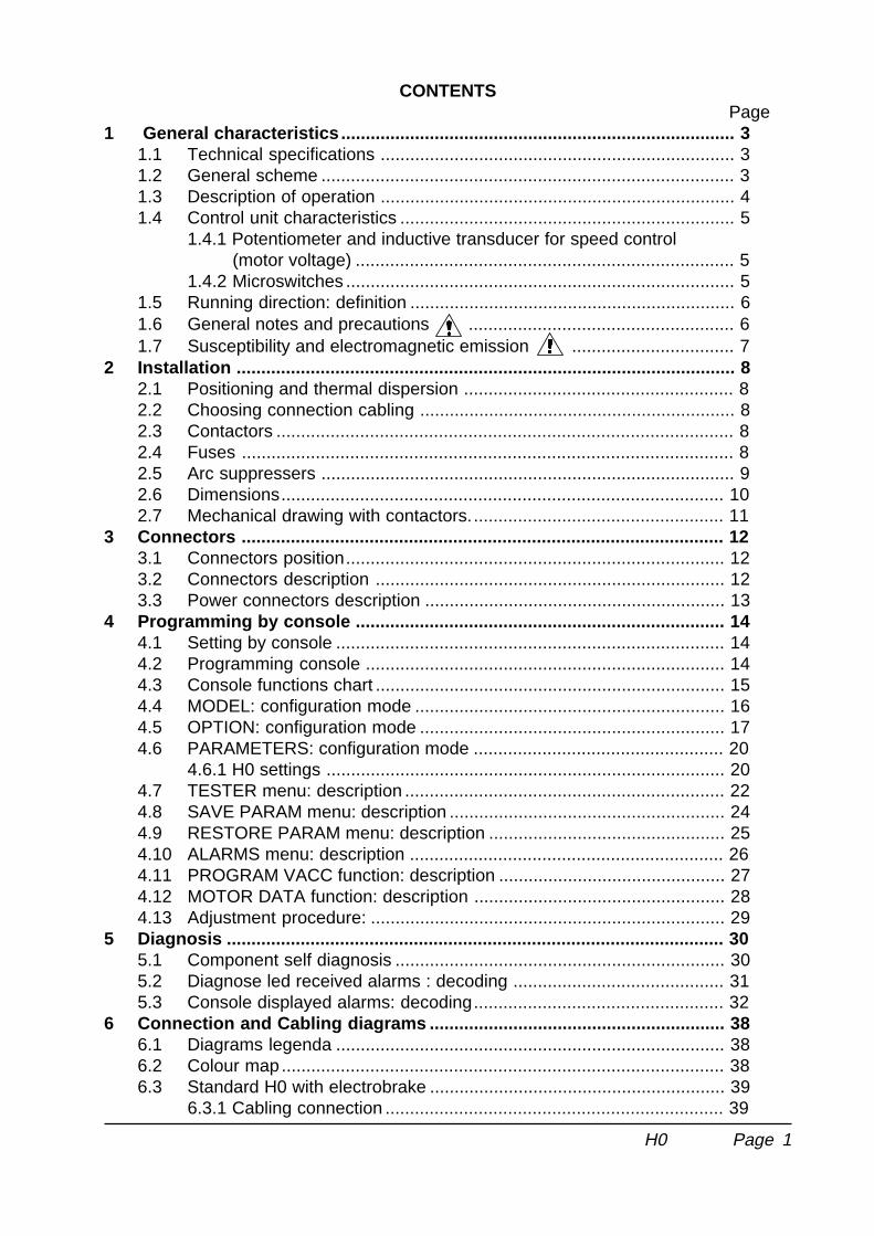
CONTENTSPage
1 General characteristics ................................................................................ 31.1 Technical specifications ........................................................................ 31.2 General scheme .................................................................................... 31.3 Description of operation ........................................................................ 41.4 Control unit characteristics .................................................................... 5
1.4.1 Potentiometer and inductive transducer for speed control (motor voltage) ............................................................................. 51.4.2 Microswitches ............................................................................... 5
1.5 Running direction: definition .................................................................. 61.6 General notes and precautions ...................................................... 61.7 Susceptibility and electromagnetic emission ................................. 7
2 Installation ..................................................................................................... 82.1 Positioning and thermal dispersion ....................................................... 82.2 Choosing connection cabling ................................................................ 82.3 Contactors ............................................................................................. 82.4 Fuses .................................................................................................... 82.5 Arc suppressers .................................................................................... 92.6 Dimensions.......................................................................................... 102.7 Mechanical drawing with contactors.................................................... 11
3 Connectors .................................................................................................. 123.1 Connectors position............................................................................. 123.2 Connectors description ....................................................................... 123.3 Power connectors description ............................................................. 13
4 Programming by console ........................................................................... 144.1 Setting by console ............................................................................... 144.2 Programming console ......................................................................... 144.3 Console functions chart ....................................................................... 154.4 MODEL: configuration mode ............................................................... 164.5 OPTION: configuration mode .............................................................. 174.6 PARAMETERS: configuration mode ................................................... 20
4.6.1 H0 settings ................................................................................. 204.7 TESTER menu: description ................................................................. 224.8 SAVE PARAM menu: description ........................................................ 244.9 RESTORE PARAM menu: description ................................................ 254.10 ALARMS menu: description ................................................................ 264.11 PROGRAM VACC function: description .............................................. 274.12 MOTOR DATA function: description ................................................... 284.13 Adjustment procedure: ........................................................................ 29
5 Diagnosis ..................................................................................................... 305.1 Component self diagnosis ................................................................... 305.2 Diagnose led received alarms : decoding ........................................... 315.3 Console displayed alarms: decoding................................................... 32
6 Connection and Cabling diagrams ............................................................ 386.1 Diagrams legenda ............................................................................... 386.2 Colour map.......................................................................................... 386.3 Standard H0 with electrobrake ............................................................ 39
6.3.1 Cabling connection ..................................................................... 39
H0
Page 2
6.3.2 Power configuration.................................................................... 396.4 Standard H0 with by-pass ................................................................... 40
6.4.1 Cabling connection ..................................................................... 406.4.2 Power configuration.................................................................... 40
6.5 Standard H0 with general contactor .................................................... 416.5.1 Cabling connection ..................................................................... 416.5.2 Power configuration.................................................................... 41
6.6 H0 autostop ......................................................................................... 426.6.1 Controls connection.................................................................... 426.6.2 Power configuration.................................................................... 42
6.7 H0 : Europe type quick inversion connection ...................................... 436.7.1 H0 autostop IRE ......................................................................... 436.7.2 H0 standard IRE ........................................................................ 44
6.8 Power configuration with 3 cables series motors ................................ 446.8.1 With contactors........................................................................... 446.8.2 With forth braking cable and standard contactors ...................... 44
6.9 Power configuration with permanent magnet motors .......................... 446.10 Guide drawing for pallet trucks connection ......................................... 456.11 Optional fuse-keeper board ................................................................. 46
7 Periodic maintenance to be repeated ............................................................ 478 Reccomended spare parts ............................................................................ 48
= Information provided within paragraphs marked by this symbol are absolutelyimportant in view of ensure safety.
SIGNATURE TABLE
COMPANY DEPT. SERVICES MANAGEMENT EXECUTIVE
ENGINEERING SECTION EXECUTIVE
EXPORT MANAGER
Publication n. AB2ZP0EAEdition: June 1995
H0
Page 3
1 GENERAL CHARACTERISTICS
1.1 TECHNICAL SPECIFICATIONS
Operating voltage: .................................................................................. type model 24V................................................................................... type model36V
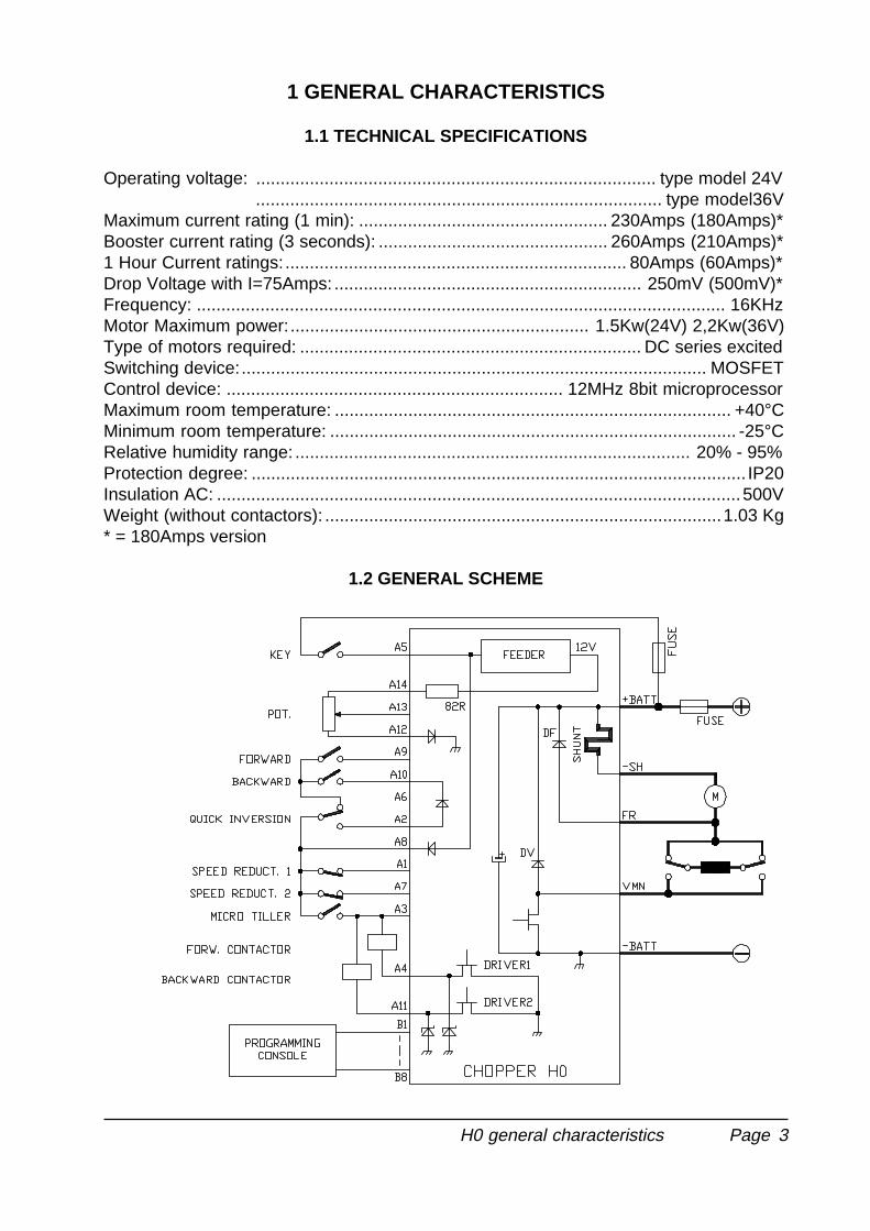
Maximum current rating (1 min): ................................................... 230Amps (180Amps)*Booster current rating (3 seconds): ............................................... 260Amps (210Amps)*1 Hour Current ratings: ...................................................................... 80Amps (60Amps)*Drop Voltage with I=75Amps: ............................................................... 250mV (500mV)*Frequency: ............................................................................................................ 16KHzMotor Maximum power:............................................................. 1.5Kw(24V) 2,2Kw(36V)Type of motors required: ...................................................................... DC series excitedSwitching device:............................................................................................... MOSFETControl device: ..................................................................... 12MHz 8bit microprocessorMaximum room temperature: ................................................................................. +40°CMinimum room temperature: ................................................................................... -25°CRelative humidity range: ................................................................................. 20% - 95%Protection degree: ..................................................................................................... IP20Insulation AC: ...........................................................................................................500VWeight (without contactors): .................................................................................1.03 Kg* = 180Amps version
1.2 GENERAL SCHEME
H0 general characteristics
Page 4
1.3 DESCRIPTION OF OPERATION
- Two configurations are available:
1) AUTOSTOP configuration: releasing forward running, an adjustable braking modeis automatically accomplished by the device.
2) STANDARD configuration: electric braking is available only inverting runningdirection; anyway you can use an auxiliary output for the electrobrake or by-passor general contactor.
- By console all adjusting and option-configuring parameters range is programmable(see chapter 4).
- Diagnostic led placed on console connector.
- Motor plugging electric braking; braking intensity controlled via current.
- Complete and broad diagnosis on each chopper’s element: any functional irregularityor component’s fault is detected, displayed or revealed and cause a safety procedurestart (running halts).
- Quick inversion: activated with an appropriate safe micro, if you’re running forward. Itconsists of a strong braking and consequent start in backward direction with constantspeed.
- Speed reduction with ohmic drop compensation. You can choose within 2 differentoperating modes:
1°: both speed reductions are selected the slower prevails.
2°: both speed reductions are selected, a 70% of slower speed is provided.
- A permanent magnet motor can be used changing programming setting for a correcthandling.
- You can handle electro-brake in standard configuration.
- Acceleration stroke programmable
- Accomplished in conformity to 86/663 rules referring to points 9.7.3.5.5 and 9.7.3.1.7
- Accomplished in conformity to DRAFT PREN 1175 rules with reference to points5.9.3, 5.9.4, 5.9.5, 5.13, 5.14, 5.15.
H0 general characteristics
Page 5
1.4 CONTROL UNITS CHARACTERISTICS
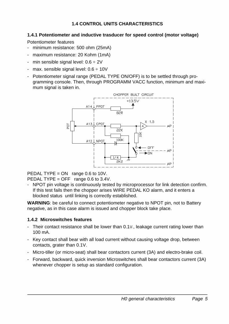
1.4.1 Potentiometer and inductive trasducer for speed control (motor voltage)
Potentiometer features- minimum resistance: 500 ohm (25mA)
- maximum resistance: 20 Kohm (1mA)
- min sensible signal level: 0.6 ÷ 2V
- max. sensible signal level: 0.6 ÷ 10V
- Potentiometer signal range (PEDAL TYPE ON/OFF) is to be settled through pro-gramming console. Then, through PROGRAMM VACC function, minimum and maxi-mum signal is taken in.
PEDAL TYPE = ON range 0.6 to 10V.PEDAL TYPE = OFF range 0.6 to 3.4V.- NPOT pin voltage is continuously tested by microprocessor for link detection confirm.
If this test fails then the chopper arises WIRE PEDAL KO alarm, and it enters ablocked status until linking is correctly established.
WARNING: be careful to connect potentiometer negative to NPOT pin, not to Batterynegative, as in this case alarm is issued and chopper block take place.
1.4.2 Microswitches features
- Their contact resistance shall be lower than 0.1W, leakage current rating lower than100 mA.
- Key contact shall bear with all load current without causing voltage drop, betweencontacts, grater than 0.1V.
- Micro-tiller (or micro-seat) shall bear contactors current (3A) and electro-brake coil.
- Forward, backward, quick inversion Microswitches shall bear contactors current (3A)whenever chopper is setup as standard configuration.
H0 general characteristics
Page 6
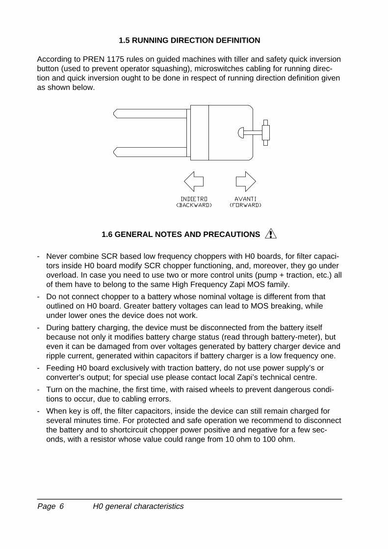
1.5 RUNNING DIRECTION DEFINITION
According to PREN 1175 rules on guided machines with tiller and safety quick inversionbutton (used to prevent operator squashing), microswitches cabling for running direc-tion and quick inversion ought to be done in respect of running direction definition givenas shown below.
1.6 GENERAL NOTES AND PRECAUTIONS
- Never combine SCR based low frequency choppers with H0 boards, for filter capaci-tors inside H0 board modify SCR chopper functioning, and, moreover, they go underoverload. In case you need to use two or more control units (pump + traction, etc.) allof them have to belong to the same High Frequency Zapi MOS family.
- Do not connect chopper to a battery whose nominal voltage is different from thatoutlined on H0 board. Greater battery voltages can lead to MOS breaking, whileunder lower ones the device does not work.
- During battery charging, the device must be disconnected from the battery itselfbecause not only it modifies battery charge status (read through battery-meter), buteven it can be damaged from over voltages generated by battery charger device andripple current, generated within capacitors if battery charger is a low frequency one.
- Feeding H0 board exclusively with traction battery, do not use power supply’s orconverter’s output; for special use please contact local Zapi’s technical centre.
- Turn on the machine, the first time, with raised wheels to prevent dangerous condi-tions to occur, due to cabling errors.
- When key is off, the filter capacitors, inside the device can still remain charged forseveral minutes time. For protected and safe operation we recommend to disconnectthe battery and to shortcircuit chopper power positive and negative for a few sec-onds, with a resistor whose value could range from 10 ohm to 100 ohm.
H0 general characteristics

Page 7
1.7 SUSCEPTIBILITY AND ELECTROMAGNETIC EMISSION
Susceptibility and electromagnetic emission are remarkably affected by installationprocedure; attention should be applied towards electric connection path, length andtowards shielding.Therefore Zapi declines any responsibility for any sort of not correct functioning due towhat mentioned above, mostly if machine builder sould fail in undertaking test requiredby current laws (irradiate emission, EN 50081-2).
H0 general characteristics
Page 8
2 INSTALLATION
2.1 POSITIONING AND THERMAL DISSIPATION
Chopper is to be installed on a flat metallic plate, unpainted and clean.Between the 2 surfaces a light layer of thermo-conductive grease to allow a better heatconveyance is to be laid down.Chopper has got a IP20 protection level, so it's necessary housing the chopper in sucha place to be enough protected against sprinklings and drippings.To fix the chopper make use of fitting holes on clamping plate.Verify that head-ropes and connector cabling are correctly accomplished.
2.2 CHOOSING CONNECTION CABLING
For auxiliary circuits 0.5 mm² cross-section wires shall be used.For power connection toward motor and battery 16 mm² cross-section wires shall beused.To improve chopper performance wires toward battery shall be aligned each other andas short as possible.
2.3 CONTACTORS
Choosing contactor type depending upon maximum current rating the motor is ex-pected to work.- Current soaked up through coil shall not exceed 3 Amps.
- Coil suppressers are chopper inside, therefore do not use arc-suppresser-built-incontactors.
- Do protect contactor’s contacts against dust, dirty, external agents which can lead tojeopardise performance and good functioning.
2.4 FUSES
- To protect auxiliary circuits do use a 10 Amps fuse.
- To protect power circuits do use a 160 Amps fuse; if the fuse shall protect pumpcircuit its value has to be increased as much as the amount of current soaked up bypump in full load condition.Shown value is the maximum allowed; for applications or special applications it canbe reduced.For safety reasons we recommend that you use protected fuses in order to preventthe spread of fused particles in case of blow out.
H0 installation
Page 9
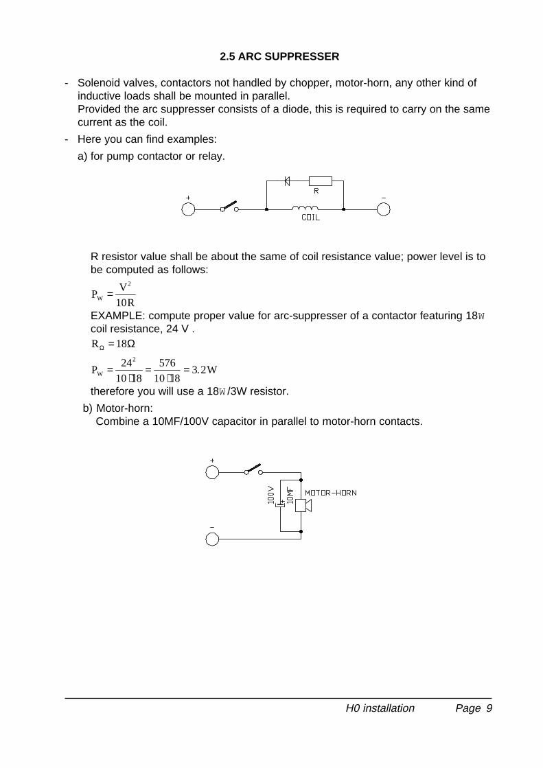
2.5 ARC SUPPRESSER
- Solenoid valves, contactors not handled by chopper, motor-horn, any other kind ofinductive loads shall be mounted in parallel.Provided the arc suppresser consists of a diode, this is required to carry on the samecurrent as the coil.
- Here you can find examples:
a) for pump contactor or relay.
R resistor value shall be about the same of coil resistance value; power level is tobe computed as follows:
PV
10RW
2
=
EXAMPLE: compute proper value for arc-suppresser of a contactor featuring 18Wcoil resistance, 24 V .RΩ Ω= 18
P24
10 18
576
10 183.2WW
2
=⋅
=⋅
=
therefore you will use a 18W/3W resistor.
b) Motor-horn:Combine a 10MF/100V capacitor in parallel to motor-horn contacts.
H0 installation

Page 10
2.6 DIMENSIONS
H0 installation

Page 11
2.7 MECHANICAL DRAWING WITH CONTACTORS
H0 installation
Page 12
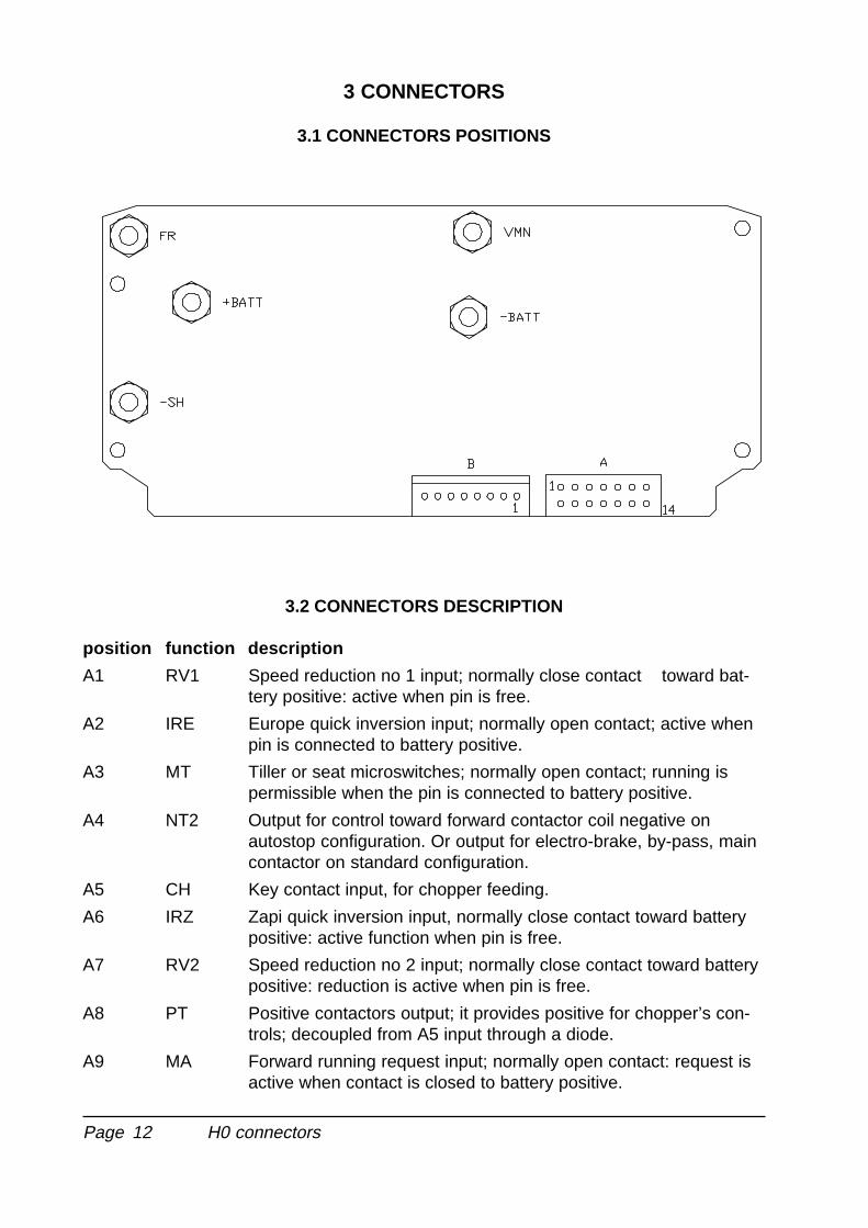
3 CONNECTORS
3.1 CONNECTORS POSITIONS
3.2 CONNECTORS DESCRIPTION
position function description
A1 RV1 Speed reduction no 1 input; normally close contact toward bat-tery positive: active when pin is free.
A2 IRE Europe quick inversion input; normally open contact; active whenpin is connected to battery positive.
A3 MT Tiller or seat microswitches; normally open contact; running ispermissible when the pin is connected to battery positive.
A4 NT2 Output for control toward forward contactor coil negative onautostop configuration. Or output for electro-brake, by-pass, maincontactor on standard configuration.
A5 CH Key contact input, for chopper feeding.
A6 IRZ Zapi quick inversion input, normally close contact toward batterypositive: active function when pin is free.
A7 RV2 Speed reduction no 2 input; normally close contact toward batterypositive: reduction is active when pin is free.
A8 PT Positive contactors output; it provides positive for chopper’s con-trols; decoupled from A5 input through a diode.
A9 MA Forward running request input; normally open contact: request isactive when contact is closed to battery positive.
H0 connectors
Page 13
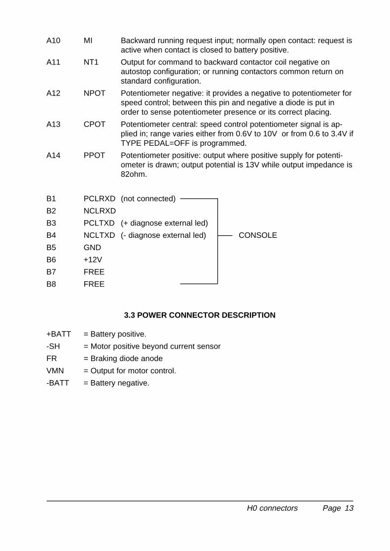
A10 MI Backward running request input; normally open contact: request isactive when contact is closed to battery positive.
A11 NT1 Output for command to backward contactor coil negative onautostop configuration; or running contactors common return onstandard configuration.
A12 NPOT Potentiometer negative: it provides a negative to potentiometer forspeed control; between this pin and negative a diode is put inorder to sense potentiometer presence or its correct placing.
A13 CPOT Potentiometer central: speed control potentiometer signal is ap-plied in; range varies either from 0.6V to 10V or from 0.6 to 3.4V ifTYPE PEDAL=OFF is programmed.
A14 PPOT Potentiometer positive: output where positive supply for potenti-ometer is drawn; output potential is 13V while output impedance is82ohm.
B1 PCLRXD (not connected)
B2 NCLRXD
B3 PCLTXD (+ diagnose external led)
B4 NCLTXD (- diagnose external led) CONSOLE
B5 GND
B6 +12V
B7 FREE
B8 FREE
3.3 POWER CONNECTOR DESCRIPTION
+BATT = Battery positive.
-SH = Motor positive beyond current sensor
FR = Braking diode anode
VMN = Output for motor control.
-BATT = Battery negative.
H0 connectors
Page 14
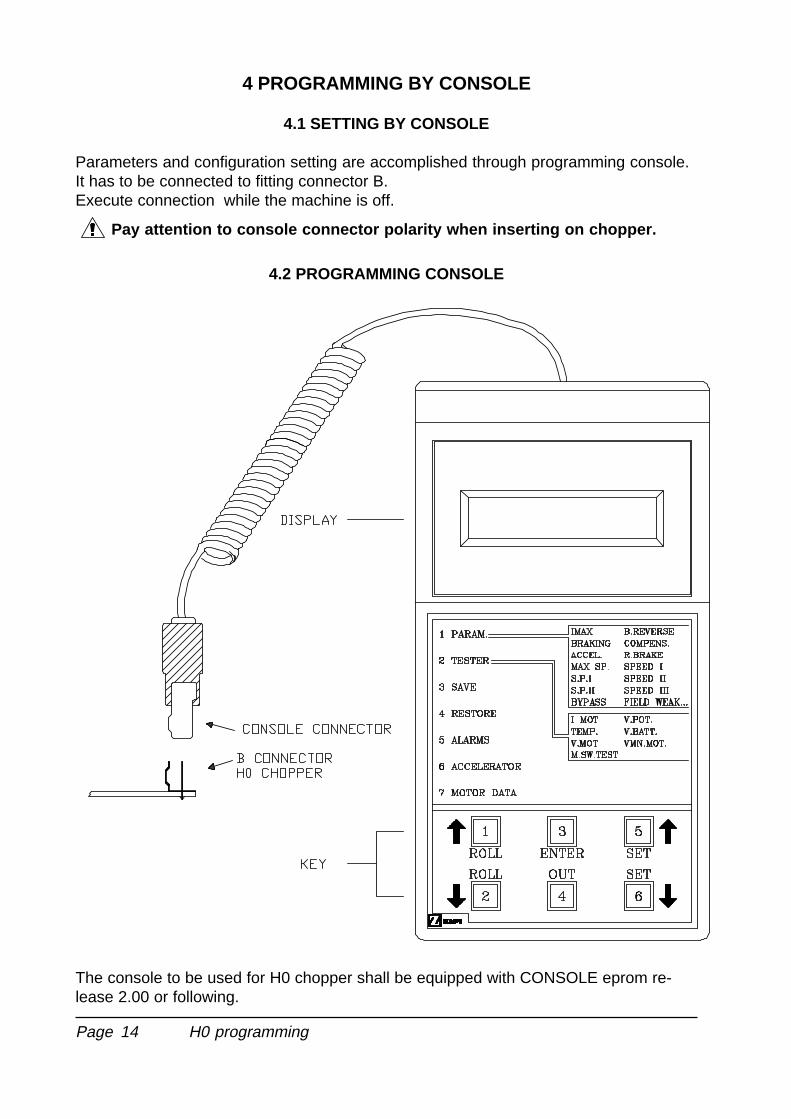
4 PROGRAMMING BY CONSOLE
4.1 SETTING BY CONSOLE
Parameters and configuration setting are accomplished through programming console.It has to be connected to fitting connector B.Execute connection while the machine is off.
Pay attention to console connector polarity when inserting on chopper.
4.2 PROGRAMMING CONSOLE
The console to be used for H0 chopper shall be equipped with CONSOLE eprom re-lease 2.00 or following.
H0 programming
Page 15
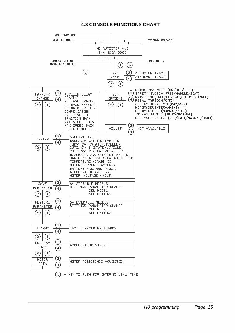
4.3 CONSOLE FUNCTIONS CHART
H0 programming
Page 16
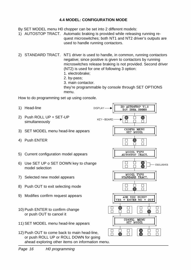
4.4 MODEL: CONFIGURATION MODE
By SET MODEL menu H0 chopper can be set into 2 different models:1) AUTOSTOP TRACT. Automatic braking is provided while releasing running re-
quest microswitches; both NT1 and NT2 driver’s outputs areused to handle running contactors.
2) STANDARD TRACT. NT1 driver is used to handle, in common, running contactorsnegative; since positive is given to contactors by runningmicroswitches release braking is not provided. Second driver(NT2) is used for one of following 3 option:1. electrobrake;2. by-pass;3. main contactor.they’re programmable by console through SET OPTIONSmenu.
How to do programming set up using console.
1) Head-line
2) Push ROLL UP + SET-UPsimultaneously
3) SET MODEL menu head-line appears
4) Push ENTER
5) Current configuration model appears
6) Use SET UP o SET DOWN key to changemodel selection
7) Selected new model appears
8) Push OUT to exit selecting mode
9) Modifies confirm request appears
10) Push ENTER to confirm changeor push OUT to cancel it
11) SET MODEL menu head-line appears
12) Push OUT to come back to main head-line,or push ROLL UP or ROLL DOWN for goingahead exploring other items on information menu.
H0 programming
Page 17
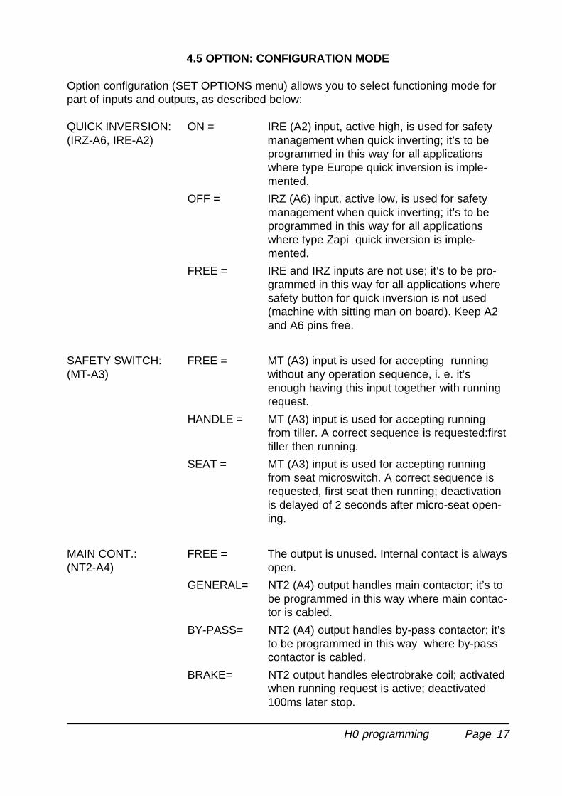
4.5 OPTION: CONFIGURATION MODE
Option configuration (SET OPTIONS menu) allows you to select functioning mode forpart of inputs and outputs, as described below:
QUICK INVERSION: ON = IRE (A2) input, active high, is used for safety(IRZ-A6, IRE-A2) management when quick inverting; it’s to be
programmed in this way for all applicationswhere type Europe quick inversion is imple-mented.
OFF = IRZ (A6) input, active low, is used for safetymanagement when quick inverting; it’s to beprogrammed in this way for all applicationswhere type Zapi quick inversion is imple-mented.
FREE = IRE and IRZ inputs are not use; it’s to be pro-grammed in this way for all applications wheresafety button for quick inversion is not used(machine with sitting man on board). Keep A2and A6 pins free.
SAFETY SWITCH: FREE = MT (A3) input is used for accepting running(MT-A3) without any operation sequence, i. e. it’s
enough having this input together with runningrequest.
HANDLE = MT (A3) input is used for accepting runningfrom tiller. A correct sequence is requested:firsttiller then running.
SEAT = MT (A3) input is used for accepting runningfrom seat microswitch. A correct sequence isrequested, first seat then running; deactivationis delayed of 2 seconds after micro-seat open-ing.
MAIN CONT.: FREE = The output is unused. Internal contact is always(NT2-A4) open.
GENERAL= NT2 (A4) output handles main contactor; it’s tobe programmed in this way where main contac-tor is cabled.
BY-PASS= NT2 (A4) output handles by-pass contactor; it’sto be programmed in this way where by-passcontactor is cabled.
BRAKE= NT2 output handles electrobrake coil; activatedwhen running request is active; deactivated100ms later stop.
H0 programming
Page 18
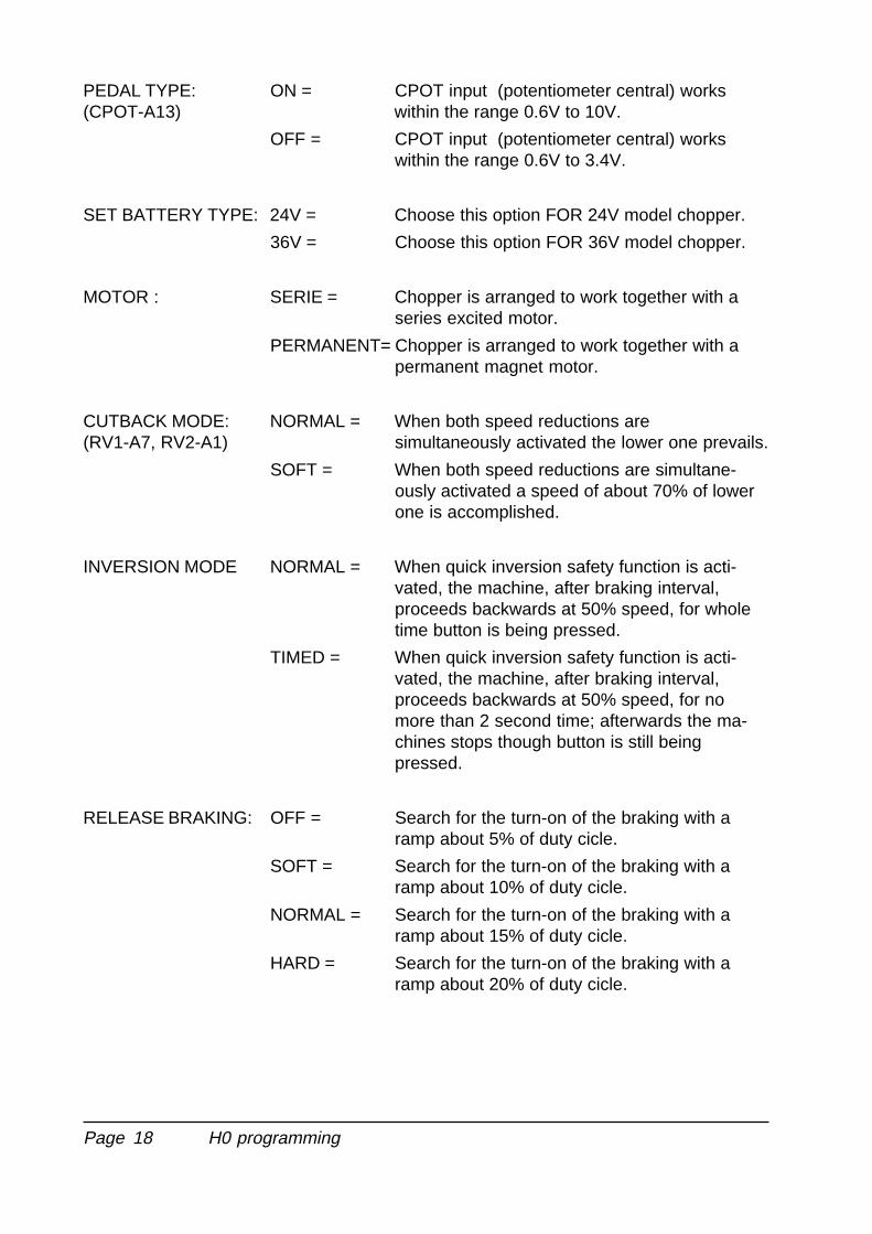
PEDAL TYPE: ON = CPOT input (potentiometer central) works(CPOT-A13) within the range 0.6V to 10V.
OFF = CPOT input (potentiometer central) workswithin the range 0.6V to 3.4V.
SET BATTERY TYPE: 24V = Choose this option FOR 24V model chopper.
36V = Choose this option FOR 36V model chopper.
MOTOR : SERIE = Chopper is arranged to work together with aseries excited motor.
PERMANENT= Chopper is arranged to work together with apermanent magnet motor.
CUTBACK MODE: NORMAL = When both speed reductions are(RV1-A7, RV2-A1) simultaneously activated the lower one prevails.
SOFT = When both speed reductions are simultane-ously activated a speed of about 70% of lowerone is accomplished.
INVERSION MODE NORMAL = When quick inversion safety function is acti-vated, the machine, after braking interval,proceeds backwards at 50% speed, for wholetime button is being pressed.
TIMED = When quick inversion safety function is acti-vated, the machine, after braking interval,proceeds backwards at 50% speed, for nomore than 2 second time; afterwards the ma-chines stops though button is still beingpressed.
RELEASE BRAKING: OFF = Search for the turn-on of the braking with aramp about 5% of duty cicle.
SOFT = Search for the turn-on of the braking with aramp about 10% of duty cicle.
NORMAL = Search for the turn-on of the braking with aramp about 15% of duty cicle.
HARD = Search for the turn-on of the braking with aramp about 20% of duty cicle.
H0 programming
Page 19
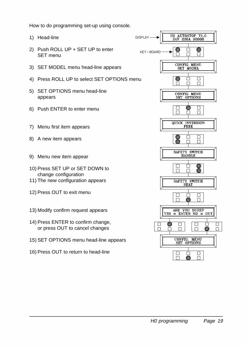
How to do programming set-up using console.
1) Head-line
2) Push ROLL UP + SET UP to enterSET menu
3) SET MODEL menu head-line appears
4) Press ROLL UP to select SET OPTIONS menu
5) SET OPTIONS menu head-lineappears
6) Push ENTER to enter menu
7) Menu first item appears
8) A new item appears
9) Menu new item appear
10) Press SET UP or SET DOWN tochange configuration
11) The new configuration appears
12) Press OUT to exit menu
13) Modify confirm request appears
14) Press ENTER to confirm change,or press OUT to cancel changes
15) SET OPTIONS menu head-line appears
16) Press OUT to return to head-line
H0 programming
Page 20
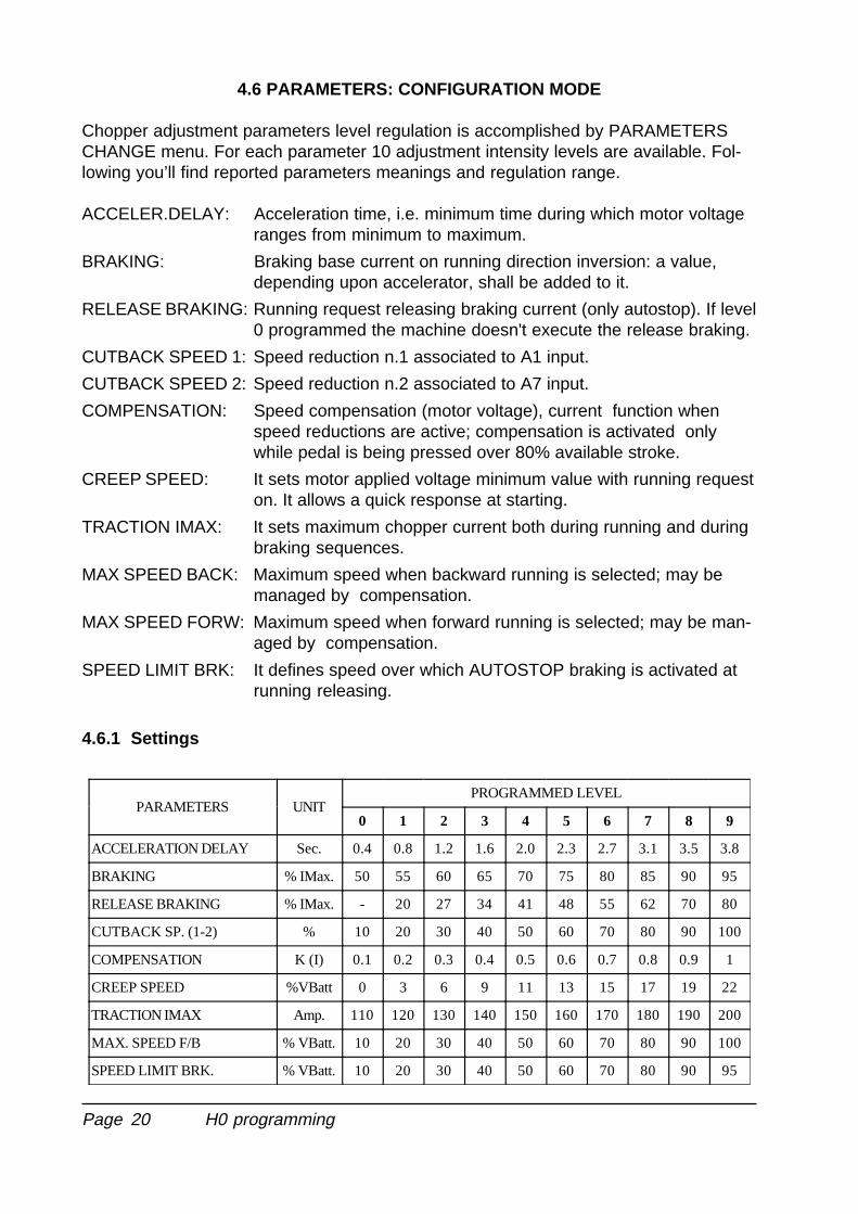
4.6 PARAMETERS: CONFIGURATION MODE
Chopper adjustment parameters level regulation is accomplished by PARAMETERSCHANGE menu. For each parameter 10 adjustment intensity levels are available. Fol-lowing you’ll find reported parameters meanings and regulation range.
ACCELER.DELAY: Acceleration time, i.e. minimum time during which motor voltageranges from minimum to maximum.
BRAKING: Braking base current on running direction inversion: a value,depending upon accelerator, shall be added to it.
RELEASE BRAKING: Running request releasing braking current (only autostop). If level0 programmed the machine doesn't execute the release braking.
CUTBACK SPEED 1: Speed reduction n.1 associated to A1 input.
CUTBACK SPEED 2: Speed reduction n.2 associated to A7 input.
COMPENSATION: Speed compensation (motor voltage), current function whenspeed reductions are active; compensation is activated onlywhile pedal is being pressed over 80% available stroke.
CREEP SPEED: It sets motor applied voltage minimum value with running requeston. It allows a quick response at starting.
TRACTION IMAX: It sets maximum chopper current both during running and duringbraking sequences.
MAX SPEED BACK: Maximum speed when backward running is selected; may bemanaged by compensation.
MAX SPEED FORW: Maximum speed when forward running is selected; may be man-aged by compensation.
SPEED LIMIT BRK: It defines speed over which AUTOSTOP braking is activated atrunning releasing.
4.6.1 Settings
PARAMETERS UNITPROGRAMMED LEVEL
0 1 2 3 4 5 6 7 8 9
ACCELERATION DELAY Sec. 0.4 0.8 1.2 1.6 2.0 2.3 2.7 3.1 3.5 3.8
BRAKING % IMax. 50 55 60 65 70 75 80 85 90 95
RELEASE BRAKING % IMax. - 20 27 34 41 48 55 62 70 80
CUTBACK SP. (1-2) % 10 20 30 40 50 60 70 80 90 100
COMPENSATION K (I) 0.1 0.2 0.3 0.4 0.5 0.6 0.7 0.8 0.9 1
CREEP SPEED %VBatt 0 3 6 9 11 13 15 17 19 22
TRACTION IMAX Amp. 110 120 130 140 150 160 170 180 190 200
MAX. SPEED F/B % VBatt. 10 20 30 40 50 60 70 80 90 100
SPEED LIMIT BRK. % VBatt. 10 20 30 40 50 60 70 80 90 95
H0 programming
Page 21
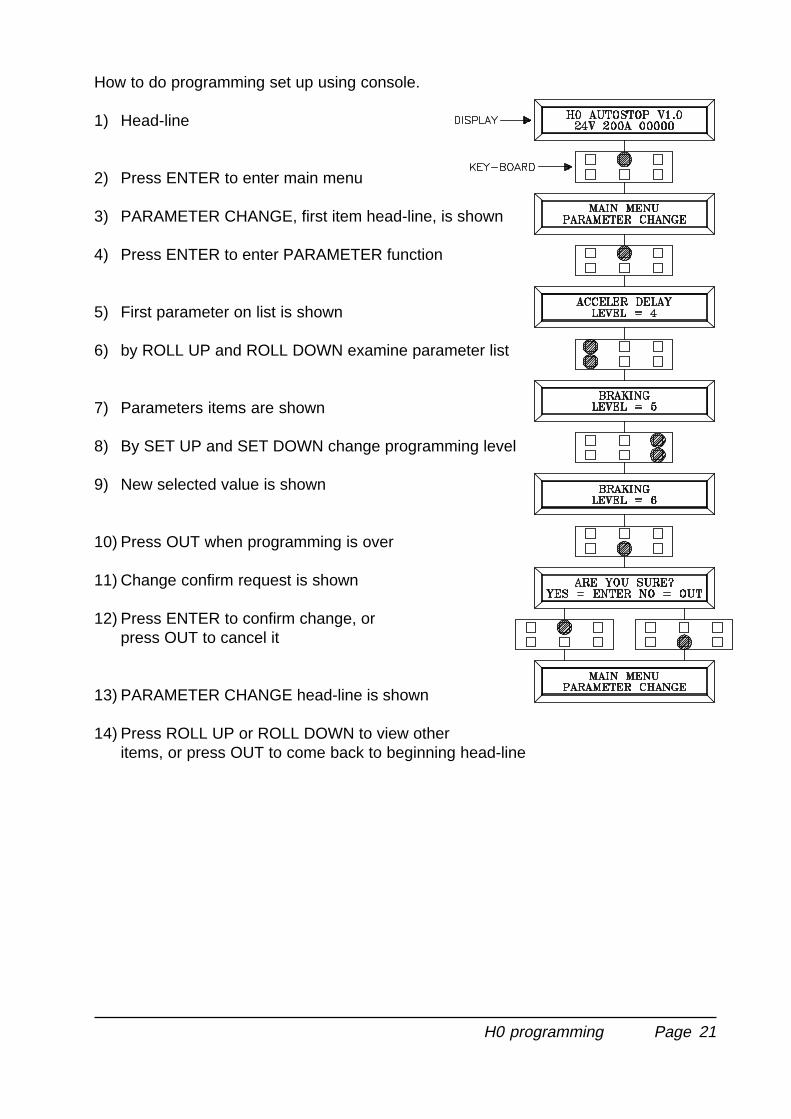
How to do programming set up using console.
1) Head-line
2) Press ENTER to enter main menu
3) PARAMETER CHANGE, first item head-line, is shown
4) Press ENTER to enter PARAMETER function
5) First parameter on list is shown
6) by ROLL UP and ROLL DOWN examine parameter list
7) Parameters items are shown
8) By SET UP and SET DOWN change programming level
9) New selected value is shown
10) Press OUT when programming is over
11) Change confirm request is shown
12) Press ENTER to confirm change, orpress OUT to cancel it
13) PARAMETER CHANGE head-line is shown
14) Press ROLL UP or ROLL DOWN to view otheritems, or press OUT to come back to beginning head-line
H0 programming

Page 22
4.7 CONSOLE TESTER MENU: DESCRIPTION
Some of more important input/output signals can be tested in real time using consoletester function. Below you find a list of tested signals and their meanings:
VMN: Voltage mean value measured between Battery negative and VMNclamp.Capacity=42.5V, resolution=0.2V, accuracy = ±3%.
BACK SW: it’s backward running digital input status (MI pin A10)
ON/+VB= ( ) active input, voltage on connector
OFF/GND = ( ) not active input, free connector.
FORW SW: it’s forward running digital input status (MA pin A9)
ON/+VB= ( ) active input, voltage on connector
OFF/GND = ( ) not active input, free connector.
CUTB.SW 1: it’s speed reduction n.1 digital input status (RV1 pin A1)
OFF/+VB= ( ) non active input, voltage on connector
ON/GND = ( ) active input, free connector.
CUTB.SW 2: it’s speed reduction n.2 digital input status (RV2 pin A7)
OFF/+VB= ( ) non active input, voltage on connector
ON/GND = ( ) active input, free connector.
INVERSION SW: Quick inversion digital input status (IRE pin A2 or IRZ pin A6).If QUICK INVERSION option is programmed ON (IRE pin A2):
ON/+VB= ( ) active input, voltage on connector
OFF/GND = ( ) not active input, free connector.
If QUICK INVERSION option is programmed OFF (IRZ pin A6):
OFF/+VB= ( ) not active input, voltage on connector
ON/GND = ( ) active input, free connector.
HANDLE /SEAT SW:Tiller approval digital input status (MT pin A3)
ON/+VB= ( ) active input, voltage on connector
OFF/GND = ( ) not active input, free connector.
TEMPERATURE: Aluminium plate temperature, near to MOSFET:range = -30°C - +100°C, resolution 2°, accuracy = ±2%
MOTOR CURRENT: It’s motor (rotor) current read through shuntCapacity=255A, resolution=1A, accuracy = ±3%.
BATTERY VOLTAGE: It’s battery voltage, read through input (CH pin A5).Capacity=42.5V, resolution=0.2V, accuracy = ±1.5%.
H0 programming
Page 23
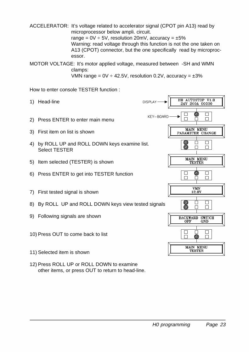
ACCELERATOR: It’s voltage related to accelerator signal (CPOT pin A13) read bymicroprocessor below ampli. circuit.range = 0V ÷ 5V, resolution 20mV, accuracy = ±5%Warning: read voltage through this function is not the one taken onA13 (CPOT) connector, but the one specifically read by microproc-essor.
MOTOR VOLTAGE: It’s motor applied voltage, measured between -SH and WMNclamps:VMN range = 0V ÷ 42.5V, resolution 0.2V, accuracy = ±3%
How to enter console TESTER function :
1) Head-line
2) Press ENTER to enter main menu
3) First item on list is shown
4) by ROLL UP and ROLL DOWN keys examine list.Select TESTER
5) Item selected (TESTER) is shown
6) Press ENTER to get into TESTER function
7) First tested signal is shown
8) By ROLL UP and ROLL DOWN keys view tested signals
9) Following signals are shown
10) Press OUT to come back to list
11) Selected item is shown
12) Press ROLL UP or ROLL DOWN to examineother items, or press OUT to return to head-line.
H0 programming
Page 24
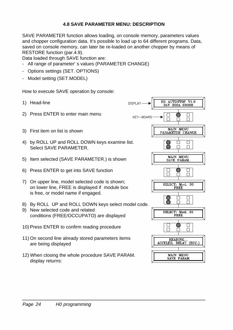
4.8 SAVE PARAMETER MENU: DESCRIPTION
SAVE PARAMETER function allows loading, on console memory, parameters valuesand chopper configuration data. It’s possible to load up to 64 different programs. Data,saved on console memory, can later be re-loaded on another chopper by means ofRESTORE function (par.4.9).Data loaded through SAVE function are:- All range of parameter’ s values (PARAMETER CHANGE)
- Options settings (SET. OPTIONS)
- Model setting (SET.MODEL)
How to execute SAVE operation by console:
1) Head-line
2) Press ENTER to enter main menu
3) First item on list is shown
4) by ROLL UP and ROLL DOWN keys examine list.Select SAVE PARAMETER.
5) Item selected (SAVE PARAMETER.) is shown
6) Press ENTER to get into SAVE function
7) On upper line, model selected code is shown;on lower line, FREE is displayed if module boxis free, or model name if engaged.
8) By ROLL UP and ROLL DOWN keys select model code.9) New selected code and related
conditions (FREE/OCCUPATO) are displayed
10) Press ENTER to confirm reading procedure
11) On second line already stored parameters itemsare being displayed
12) When closing the whole procedure SAVE PARAM.display returns:
H0 programming
Page 25
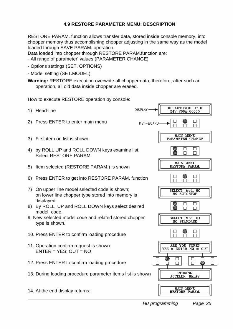
4.9 RESTORE PARAMETER MENU: DESCRIPTION
RESTORE PARAM. function allows transfer data, stored inside console memory, intochopper memory thus accomplishing chopper adjusting in the same way as the modelloaded through SAVE PARAM. operation.Data loaded into chopper through RESTORE PARAM.function are:- All range of parameter’ values (PARAMETER CHANGE)
- Options settings (SET. OPTIONS)
- Model setting (SET.MODEL)
Warning: RESTORE execution overwrite all chopper data, therefore, after such anoperation, all old data inside chopper are erased.
How to execute RESTORE operation by console:
1) Head-line
2) Press ENTER to enter main menu
3) First item on list is shown
4) by ROLL UP and ROLL DOWN keys examine list.Select RESTORE PARAM.
5) Item selected (RESTORE PARAM.) is shown
6) Press ENTER to get into RESTORE PARAM. function
7) On upper line model selected code is shown;on lower line chopper type stored into memory isdisplayed.
8) By ROLL UP and ROLL DOWN keys select desiredmodel code.
9. New selected model code and related stored choppertype is shown.
10. Press ENTER to confirm loading procedure
11. Operation confirm request is shown:ENTER = YES; OUT = NO
12. Press ENTER to confirm loading procedure
13. During loading procedure parameter items list is shown
14. At the end display returns:
H0 programming
Page 26
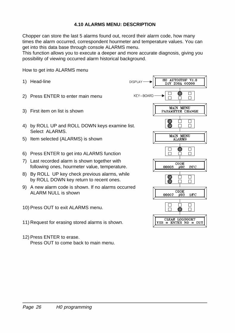
4.10 ALARMS MENU: DESCRIPTION
Chopper can store the last 5 alarms found out, record their alarm code, how manytimes the alarm occurred, correspondent hourmeter and temperature values. You canget into this data base through console ALARMS menu.This function allows you to execute a deeper and more accurate diagnosis, giving youpossibility of viewing occurred alarm historical background.
How to get into ALARMS menu
1) Head-line
2) Press ENTER to enter main menu
3) First item on list is shown
4) by ROLL UP and ROLL DOWN keys examine list.Select ALARMS.
5) Item selected (ALARMS) is shown
6) Press ENTER to get into ALARMS function
7) Last recorded alarm is shown together withfollowing ones, hourmeter value, temperature.
8) By ROLL UP key check previous alarms, whileby ROLL DOWN key return to recent ones.
9) A new alarm code is shown. If no alarms occurredALARM NULL is shown
10) Press OUT to exit ALARMS menu.
11) Request for erasing stored alarms is shown.
12) Press ENTER to erase.Press OUT to come back to main menu.
H0 programming
Page 27
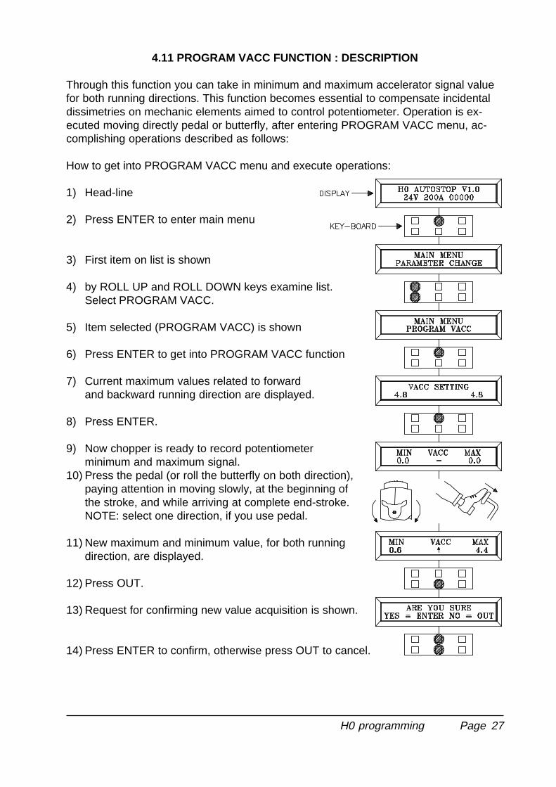
4.11 PROGRAM VACC FUNCTION : DESCRIPTION
Through this function you can take in minimum and maximum accelerator signal valuefor both running directions. This function becomes essential to compensate incidentaldissimetries on mechanic elements aimed to control potentiometer. Operation is ex-ecuted moving directly pedal or butterfly, after entering PROGRAM VACC menu, ac-complishing operations described as follows:
How to get into PROGRAM VACC menu and execute operations:
1) Head-line
2) Press ENTER to enter main menu
3) First item on list is shown
4) by ROLL UP and ROLL DOWN keys examine list.Select PROGRAM VACC.
5) Item selected (PROGRAM VACC) is shown
6) Press ENTER to get into PROGRAM VACC function
7) Current maximum values related to forwardand backward running direction are displayed.
8) Press ENTER.
9) Now chopper is ready to record potentiometerminimum and maximum signal.
10) Press the pedal (or roll the butterfly on both direction),paying attention in moving slowly, at the beginning ofthe stroke, and while arriving at complete end-stroke.NOTE: select one direction, if you use pedal.
11) New maximum and minimum value, for both runningdirection, are displayed.
12) Press OUT.
13) Request for confirming new value acquisition is shown.
14) Press ENTER to confirm, otherwise press OUT to cancel.
H0 programming
Page 28
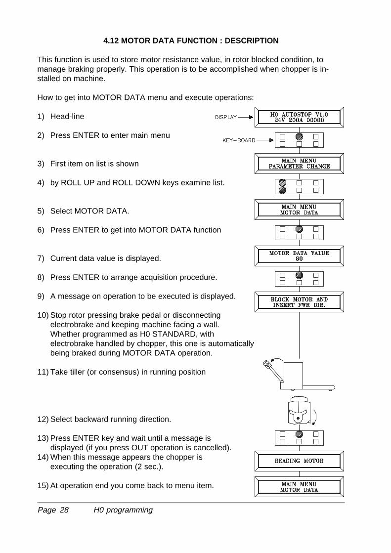
4.12 MOTOR DATA FUNCTION : DESCRIPTION
This function is used to store motor resistance value, in rotor blocked condition, tomanage braking properly. This operation is to be accomplished when chopper is in-stalled on machine.
How to get into MOTOR DATA menu and execute operations:
1) Head-line
2) Press ENTER to enter main menu
3) First item on list is shown
4) by ROLL UP and ROLL DOWN keys examine list.
5) Select MOTOR DATA.
6) Press ENTER to get into MOTOR DATA function
7) Current data value is displayed.
8) Press ENTER to arrange acquisition procedure.
9) A message on operation to be executed is displayed.
10) Stop rotor pressing brake pedal or disconnectingelectrobrake and keeping machine facing a wall.Whether programmed as H0 STANDARD, withelectrobrake handled by chopper, this one is automaticallybeing braked during MOTOR DATA operation.
11) Take tiller (or consensus) in running position
12) Select backward running direction.
13) Press ENTER key and wait until a message isdisplayed (if you press OUT operation is cancelled).
14) When this message appears the chopper isexecuting the operation (2 sec.).
15) At operation end you come back to menu item.
H0 programming
Page 29
4.13 ADJUSTMENT PROCEDURE
While the truck is off, connect programming console, switch on, head-line appears ondisplay.If the chopper has bready bean configured into the model requested (autostop or stand-ard) go to point 3; otherwise proceed as follows:
1) Configure chopper model: choose a model fitting to the function requested and thecabling used. (see par. 4.4).
2) Configure options (see par. 4.5).
3) Verify perfect functionality of all cabled inputs, including potentiometer, using con-sole TESTER function (see par. 4.7).
4) Execute acquisition of accelerator signal with PROGRAM VACC menu (see par.4.11)
5) Select maximum current value, programming it at a desired value level, as reportedon H0 regulating schedule (see par. 4.6.1).
6) Execute MOTOR DATA, as described at par. 4.12.
7) Adjust CREEP value, starting from 0 level; while machine is off press lightly pedal inorder to trigger running microswitch, leaving potentiometer at minimum value, thenarise CREEP level until the machine starts moving.
8) Adjust acceleration (ACCELERATION DELAY) making some standing-starts in bothdirections.
9) Release braking (RELEASE BRAKING) should be adjusted launching machine,then releasing entirely pedal or butterfly and selecting desired intensity.To have a better working you must employ the right trip level of braking turn-onramp. To do that you shall work on the parameter RELEASE BRAKING into themenu options choosing which on of the four levels (OFF / SOFT / NORMAL /HARD) is the most opportune. Too much low trip level could not let the turn-onbraking, while too much high trip level cause a harsh turn-on.
10) Inversion braking (BRAKING) is tested launching machine, then inverting runningdirection request: choose desired braking intensity.
11) Speed reduction (CUTBACK SP1 and CUTBACK SP2) shall be adjusted first withunloaded truck on flat ground, setting COMPENSATION parameter at 0 level; oncedefined the desired speed put on load and adjust COMPENSATION (feedback)parameter until you achieve desired speed.
12) Forward/backward maximum speed (MAX SPEED FORW and MAX SPEED BACK)shall be adjusted depending upon needs and can be subordinate to compensationlike as reduction speeds.
H0 programming

Page 30
5 DIAGNOSIS
5.1 COMPONENT SELF DIAGNOSIS
Microprocessor carries out diagnosis over main chopper functions, involving 4 basicpoints:1) diagnosis on key start-up which includes: WatchDog test, current sensor test, power
mosfet test, contactor drivers test, test for running request present, accelerator test,EEPROM test.
2) Stand-by diagnosis which includes: WatchDog test, power mosfet test, current test,contactor drivers test, accelerator test.
3) Diagnosis while running which includes: WatchDog test, power mosfet test, currenttest, contactor drivers test, accelerator test, contactor opening-closing test.
4) Parameter diagnosis: temperature check, battery charge test.
The diagnostic message on possible fault, is indicated by a certain number of blinks ofthe LED connected to connector A (see par. 5.2).The current alarm message code can be displayed on the programming console (seepar. 5.3).
H0 diagnosis
Page 31
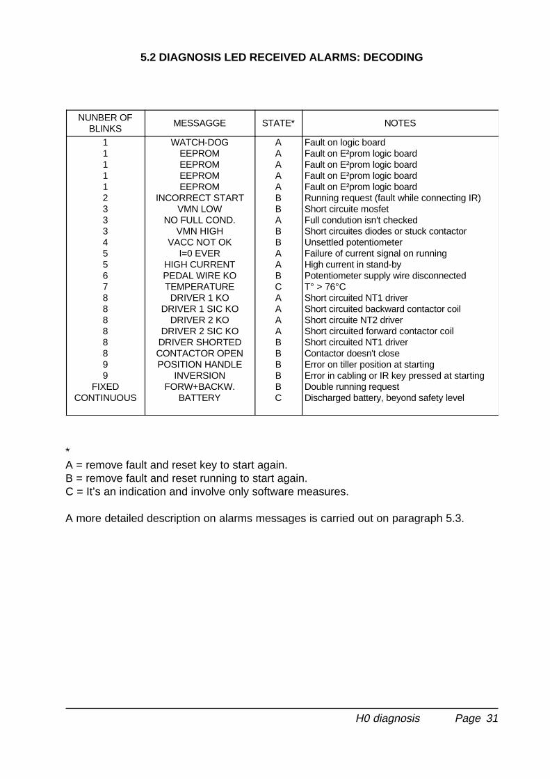
5.2 DIAGNOSIS LED RECEIVED ALARMS: DECODING
NUNBER OFBLINKS
MESSAGGE STATE* NOTES
1111123334556788888899
FIXEDCONTINUOUS
WATCH-DOGEEPROMEEPROMEEPROMEEPROM
INCORRECT STARTVMN LOW
NO FULL COND.VMN HIGH
VACC NOT OKI=0 EVER
HIGH CURRENTPEDAL WIRE KOTEMPERATUREDRIVER 1 KO
DRIVER 1 SIC KODRIVER 2 KO
DRIVER 2 SIC KODRIVER SHORTEDCONTACTOR OPENPOSITION HANDLE
INVERSIONFORW+BACKW.
BATTERY
AAAAABBABBAABCAAAABBBBBC
Fault on logic boardFault on E²prom logic boardFault on E²prom logic boardFault on E²prom logic boardFault on E²prom logic boardRunning request (fault while connecting IR)Short circuite mosfetFull condution isn't checkedShort circuites diodes or stuck contactorUnsettled potentiometerFailure of current signal on runningHigh current in stand-byPotentiometer supply wire disconnectedT° > 76°CShort circuited NT1 driverShort circuited backward contactor coilShort circuite NT2 driverShort circuited forward contactor coilShort circuited NT1 driverContactor doesn't closeError on tiller position at startingError in cabling or IR key pressed at startingDouble running requestDischarged battery, beyond safety level
*A = remove fault and reset key to start again.B = remove fault and reset running to start again.C = It’s an indication and involve only software measures.
A more detailed description on alarms messages is carried out on paragraph 5.3.
H0 diagnosis
Page 32
5.3 CONSOLE DISPLAYED ALARMS: DECODING
In this paragraph console alarm message meanings, both those displayed during analarm in progress and those stored into memory within ALARM menu are reported.
1) WATCHDOGThe test is made in both running and standby. It is a self-diagnosis test within thelogic, and executes a cross software and hardware verify. If this alarm should occur,replace the logic.
2) EEPROM PAR.KOFault in the area of memory in which the adjustment parameters are stored. Thisalarm inhibits machine operation. If the defect persists when the key is switched offand on again, replace the logic. If the alarm disappears, remember that the param-eters stored previously have been cancelled and replaced by the default values.
3) EEPROM CONF.KOFault in the area of memory in which the special chopper configuration data isstored. If the defect persists when the key is switched off and on again, replace thelogic. Otherwise, keep in mind that the chopper configuration has been reset to thedefault values; thus it must be reprogrammed. consult the console manual.par 4.4,4.5, 4.6.
4) EEPROM DATA KOThe data in the area of memory for the hour-metre is incorrect. This alarm does notshut down the machine. If the alarm disappears when the key is switched off and onagain, keep in mind that the hour-metre data has been reset to zero.
5) EEPROM OFF LINEFault in the nonvolatile memory that contains data relative to the area for the hour-metre, the alarms stored and the programming parameters.If the alarm persists when the key is switched off and on again, replace the logic.
6) INCORRECT STARTAn incorrect starting sequence. The machine only starts if this sequence is followed:1 key / 2 handle / 3 running (if safety switch = handle)1 key / 2 running (if safety switch = free)1 key + seat / 2 running (if safety switch = seat)Possible causes:
a) Running microswitch stuck.
b) Error in sequence executed by the operator, id est running request previous tokey start-up or before pulling down tiller.
c) Incorrect wiring. If nothing wrong is detected may be the fault is inside chopper,which has to be replaced.
H0 diagnosis
Page 33
7) VMN LOWIt shows that voltage on VMN bar is low (<30% VD); usually this voltage should rate1/2 battery voltage, when contactors are open. The test is carried out at standbyand in running up to 80% of PWM.Possible causes:
a) If main contactor is installed either it does not close and it’s likely not connectedor resistor, presumably placed in parallel to contacts, is blown up.
b) Check if there are metallic particles thus causing short circuit between VMNcabling and battery negative cabling (-B).
c) Power mosfet shorted or continuously piloted by logic: to verify that disconnectthe cable away from VMN bar, then start the device; if the fault is lasting replacethe chopper.
d) If by-pass contactor is installed, verify either it’s not stuck or excessively slowwhen opening.
8) VMN HIGHIt indicates that voltage on VMN bar is high (> 70% VB); usually this voltage shouldbe 1/2 battery voltage. Possible causes:
a) Running contactor is ever closed for either it’s stuck or it is ever supplied due to awrong wiring toward coil.
b) Either a current dispersion or a short circuit between stator and rotor winding isfound out: to verify it disconnect VMN bar cable and the alarm should disappear.Motor is to be repaired.
c) Motor cabling connection error: check carefully that rotor and stator are exactlycabled as shown on schemes.
d) Defects on chopper power board due to either flywhell or braking diode, whichmay be shorted. To verify that defect is on chopper, disconnect VMN bar cable,then if alarm remains replace chopper.
9) VACC NOT OKThe test is made in standby. The alarm indicates that the accelerator voltage isgreater than 1V with respect to the minimum value stored with PROGRAM VACCfunction. Most likely reason is that either potentiometer or inductive sensor (in pedalor tiller) become unsettled.
10) I=0 EVERTest carried out in running. Checks that the current during running is greater than aminimum value. If not, an alarm is signalled.Possible causes:
a) Motor resistance is too high due to motor fault or more often brushes contacts.
b) The current sensor is faulty. Replace the power unit.
11) HIGH CURRENTChopper discovers current signal greater than 50A when the machine is in standbywith open contactors. It’s most likely chopper current sensor is faulty; replace thechopper.
H0 diagnosis
Page 34
12) PEDAL WIRE KOOn NPOT pin (A12), where potentiometer negative is connected, no voltage isdetected, thus indicating that potentiometer is not supplied due 1 of 2 supply wirescut off.Possible causes:
a) wire toward PPOT (A14) is disconnected
b) wire toward NPOT (A12) is disconnected
c) Potentiometer resistance is cut off.
d) Potentiometer presents a resistance greater than 47Kohm
13) TEMPERATUREIt’s an indication that the chopper temperature has exceeded 76°C.The maximum current is gradually reduced, reaching 0 at a temperature of 86°C.
a) If the alarm occurs at key start-up, while chopper is cold, most likely cause is abreak down on power or logic board thermal detection circuit: replace chopper.
b) If the alarms occurs many times soon after begin working, it’s likely due to insuffi-cient heat dissipation: check fixing nuts and correct installation.
14) NO FULL COND.The test is carried out in full conduction. If, in this condition, the VMN is found to begreater than 1/3 VBATT, the diagnostic circuit is faulty, causing a safety risk, andthus machine operation is inhibited. If the defect persists, replace the logic.
15) DRIVER 1 KOIndicates that NT1 (A11) connector voltage is not consistent with the expectedvalue; the machine is inhibited.Possible causes:
a) either wire toward NT1 connector is disconnected or backward contactor coil isbreak off.
b) Inside chopper mosfet is shorted; replace chopper.
16) DRIVER 1 SIC KOIt indicates a current overload on driver of contactor connected to NT1 (A11); themachine is inhibited.Possible causes:
a) Short circuit between positive and the wire toward NT1.
b) Contactor coil shorted or coil current uptake greater than 5A.
17) DRIVER 2 KOSame as point 15 but with reference to NT2 (A4) connector.
18) DRIVER 2 SIC KOSame as point 16 but with reference to NT2 (A14) connector and relative load.
19) DRIVER SHORTEDIt’s the same alarms as described at point 15, but can be found exclusively onSTANDARD TRACT. configuration.
H0 diagnosis
Page 35
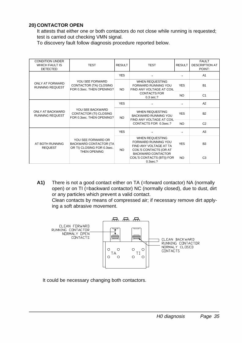
20) CONTACTOR OPENIt attests that either one or both contactors do not close while running is requested;test is carried out checking VMN signal.To discovery fault follow diagnosis procedure reported below.
CONDITION UNDERWHICH FAULT IS
DETECTEDTEST RESULT TEST RESULT
FAULTDESCRIPTION AT
POINT:
ONLY AT FORWARDRUNNING REQUEST
YOU SEE FORWARDCONTACTOR (TA) CLOSING
FOR 0.3sec. THEN OPENING?
YES → → A1
NO
WHEN REQUESTINGFORWARD RUNNING YOU
FIND ANY VOLTAGE AT COILCONTACTS FOR
0.3 sec.?
YES B1
NO C1
ONLY AT BACKWARDRUNNING REQUEST
YOU SEE BACKWARDCONTACTOR (TI) CLOSING
FOR 0.3sec. THEN OPENING?
YES → → A2
NO
WHEN REQUESTINGBACKWARD RUNNING YOU
FIND ANY VOLTAGE AT COILCONTACTS FOR 0.3sec.?
YES B2
NO C2
AT BOTH RUNNINGREQUEST
YOU SEE FORWARD ORBACKWARD CONTACTOR (TAOR TI) CLOSING FOR 0.3sec.
THEN OPENING
YES → → A3
NO
WHEN REQUESTINGFORWARD RUNNING YOUFIND ANY VOLTAGE AT TACOIL'S CONTACTS (OR ATBACKWARD CONTACTOR
COIL'S CONTACTS (BTI)) FOR0.3sec.?
YES B3
NO C3
A1) There is not a good contact either on TA (=forward contactor) NA (normallyopen) or on TI (=backward contactor) NC (normally closed), due to dust, dirtor any particles which prevent a valid contact.Clean contacts by means of compressed air; if necessary remove dirt apply-ing a soft abrasive movement.
It could be necessary changing both contactors.
H0 diagnosis
Page 36
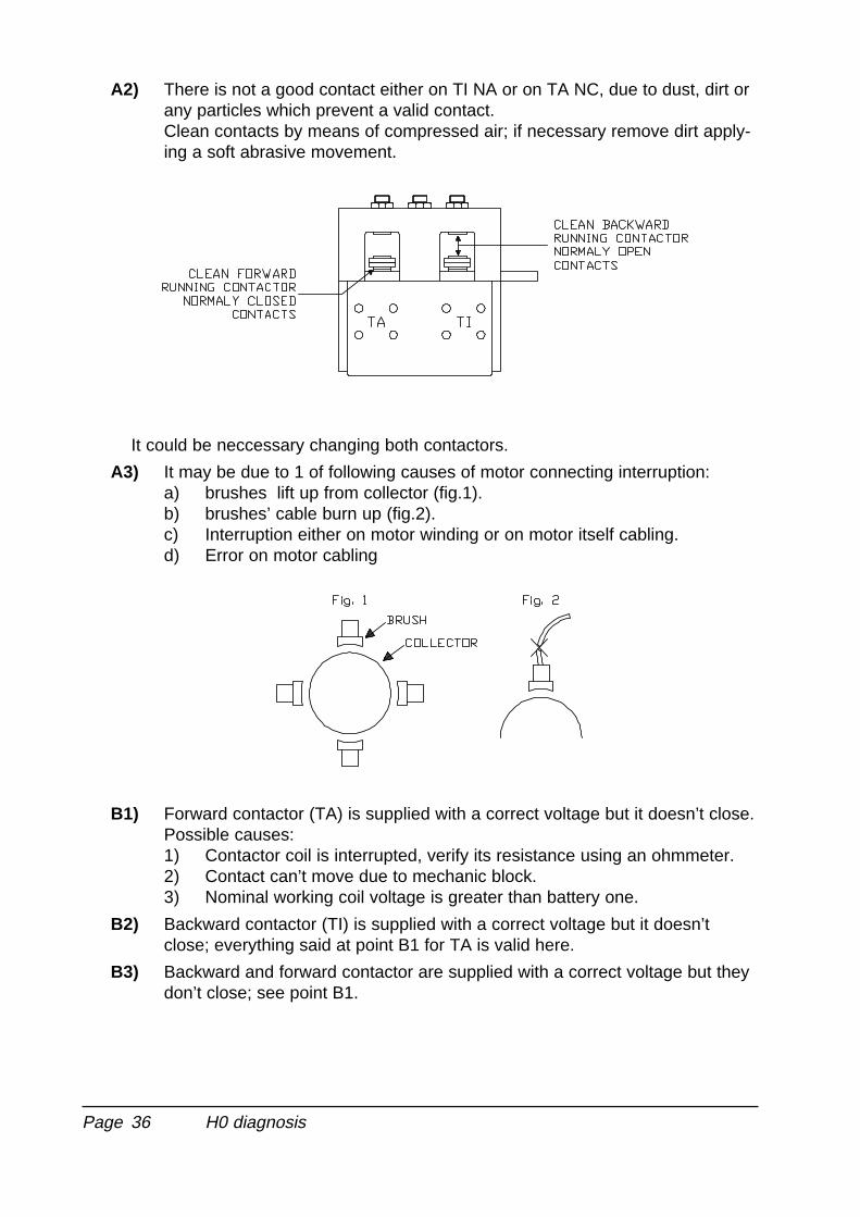
A2) There is not a good contact either on TI NA or on TA NC, due to dust, dirt orany particles which prevent a valid contact.Clean contacts by means of compressed air; if necessary remove dirt apply-ing a soft abrasive movement.
It could be neccessary changing both contactors.
A3) It may be due to 1 of following causes of motor connecting interruption:a) brushes lift up from collector (fig.1).b) brushes’ cable burn up (fig.2).c) Interruption either on motor winding or on motor itself cabling.d) Error on motor cabling
B1) Forward contactor (TA) is supplied with a correct voltage but it doesn’t close.Possible causes:1) Contactor coil is interrupted, verify its resistance using an ohmmeter.2) Contact can’t move due to mechanic block.3) Nominal working coil voltage is greater than battery one.
B2) Backward contactor (TI) is supplied with a correct voltage but it doesn’tclose; everything said at point B1 for TA is valid here.
B3) Backward and forward contactor are supplied with a correct voltage but theydon’t close; see point B1.
H0 diagnosis
Page 37
C1) Supply doesn’t come up to TA: check cabling and connections from TA coilto positive and to A4 (NT2).
C2) Supply doesn’t come up to TI: check cabling and connections from TI coil topositive and to A11 (NT1).
C3) Supply comes up neither to TI nor to TA: check cabling and connectionsfrom TI coil to positive and to A4 (NT2) and to A11 (NT1).
- For points C1, C2, C3 replacing chopper may be necessary.
21) POSITION HANDLEIt indicates that tiller was lowered into running position prior to key-start-up. Thisalarm is not activated if SAFETY SWITCH is programmed FREE.Possible causes:
a) tiller microswitch stuck.
b) Operator error relating to correct sequence.
22) INVERSIONIt indicates that quick inversion key is being pressed at key-start-up.Possible causes:
a) Quick inversion microswitch stuck.
b) Operator action error.
c) Error either in quick inversion microswitch cabling or in programming; this alarmoccurs, for example, whenever, following scheme, it’s cabled to use IRZ input,while chopper is programmed for IRE or viceversa. See par 4.5 and drawingschapter 6.
23) FORW + BACKWIt indicates a double running request. Possible causes:
a) fault in cabling
b) Operator action error.
c) If no external irregularities are found it may be necessary to replace the chopper.
24) BATTERYIt indicates that supply voltage has gone down below 60% nominal voltage.When the alarm appears the machine doesn’t move.To start again it would be enough press again butterfly: alarm remains and themachine proceeds at 50% programmed maximum current rating.
H0 diagnosis
Page 38
6 CONNECTIONS AND CABLING DIAGRAMS
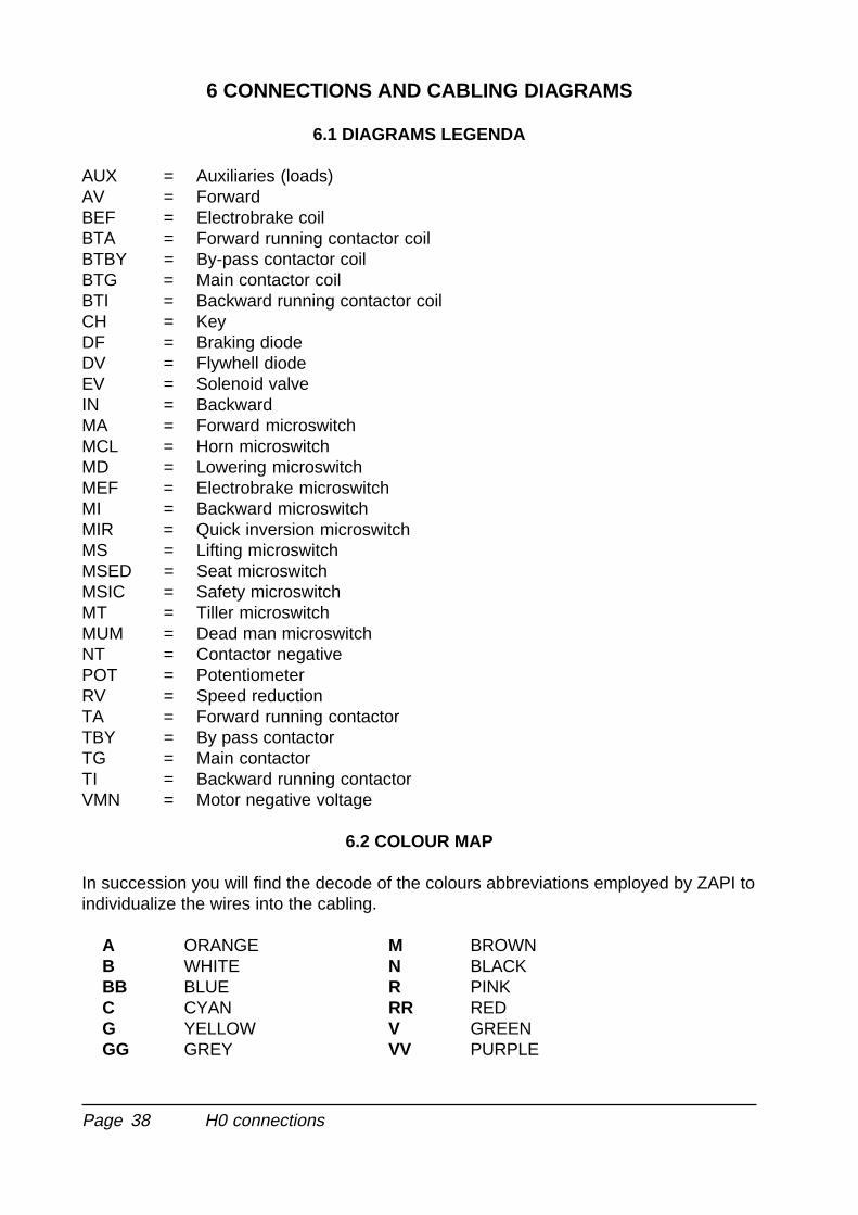
6.1 DIAGRAMS LEGENDA
AUX = Auxiliaries (loads)AV = ForwardBEF = Electrobrake coilBTA = Forward running contactor coilBTBY = By-pass contactor coilBTG = Main contactor coilBTI = Backward running contactor coilCH = KeyDF = Braking diodeDV = Flywhell diodeEV = Solenoid valveIN = BackwardMA = Forward microswitchMCL = Horn microswitchMD = Lowering microswitchMEF = Electrobrake microswitchMI = Backward microswitchMIR = Quick inversion microswitchMS = Lifting microswitchMSED = Seat microswitchMSIC = Safety microswitchMT = Tiller microswitchMUM = Dead man microswitchNT = Contactor negativePOT = PotentiometerRV = Speed reductionTA = Forward running contactorTBY = By pass contactorTG = Main contactorTI = Backward running contactorVMN = Motor negative voltage
6.2 COLOUR MAP
In succession you will find the decode of the colours abbreviations employed by ZAPI toindividualize the wires into the cabling.
A ORANGE M BROWNB WHITE N BLACKBB BLUE R PINKC CYAN RR REDG YELLOW V GREENGG GREY VV PURPLE
H0 connections
Page 39
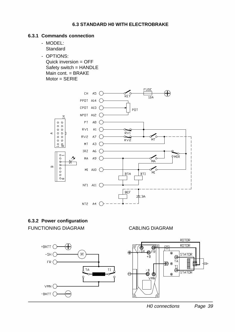
6.3 STANDARD H0 WITH ELECTROBRAKE
6.3.1 Commands connection
- MODEL:Standard
- OPTIONS:Quick inversion = OFFSafety switch = HANDLEMain cont. = BRAKEMotor = SERIE
6.3.2 Power configuration
FUNCTIONING DIAGRAM CABLING DIAGRAM
H0 connections
Page 40
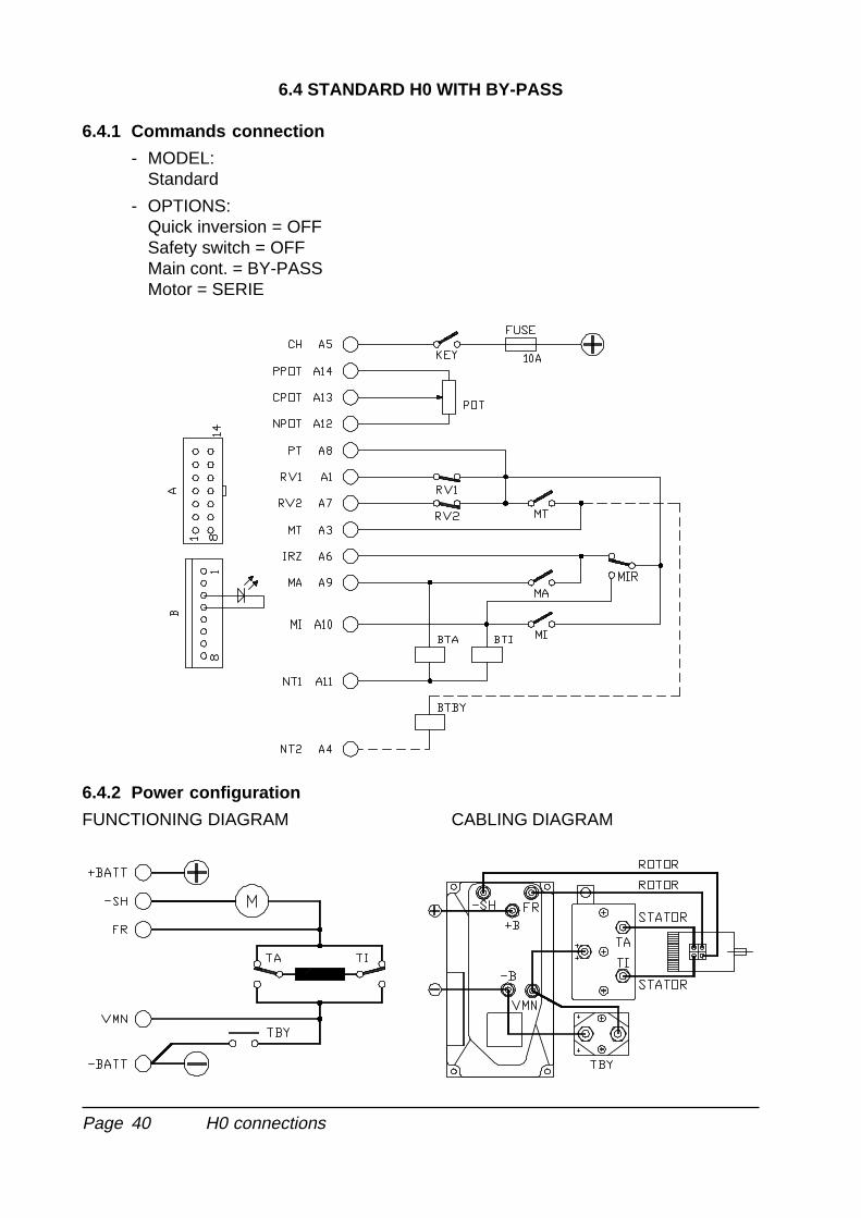
6.4 STANDARD H0 WITH BY-PASS
6.4.1 Commands connection
- MODEL:Standard
- OPTIONS:Quick inversion = OFFSafety switch = OFFMain cont. = BY-PASSMotor = SERIE
6.4.2 Power configuration
FUNCTIONING DIAGRAM CABLING DIAGRAM
H0 connections
Page 41
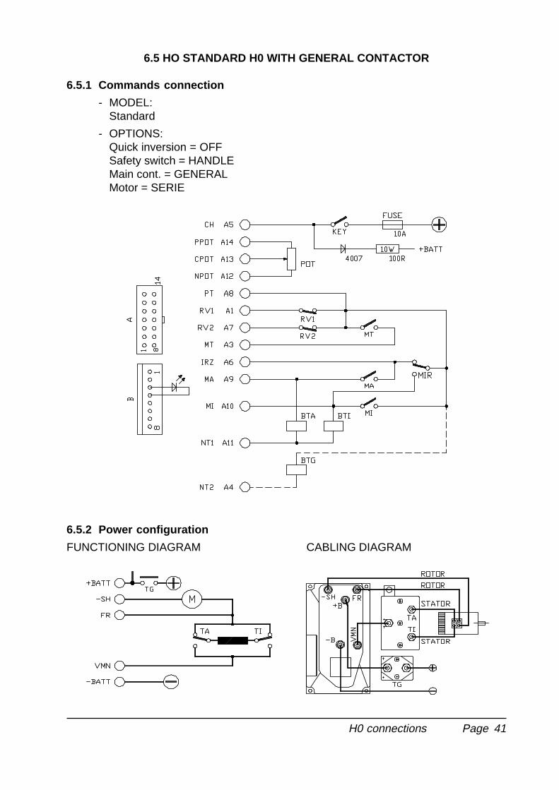
6.5 HO STANDARD H0 WITH GENERAL CONTACTOR
6.5.1 Commands connection
- MODEL:Standard
- OPTIONS:Quick inversion = OFFSafety switch = HANDLEMain cont. = GENERALMotor = SERIE
6.5.2 Power configuration
FUNCTIONING DIAGRAM CABLING DIAGRAM
H0 connections
Page 42
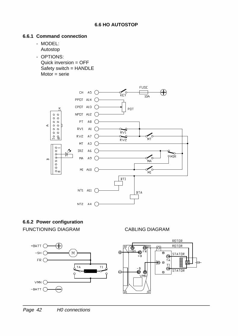
6.6 HO AUTOSTOP
6.6.1 Command connection
- MODEL:Autostop
- OPTIONS:Quick inversion = OFFSafety switch = HANDLEMotor = serie
6.6.2 Power configuration
FUNCTIONING DIAGRAM CABLING DIAGRAM
H0 connections
Page 43
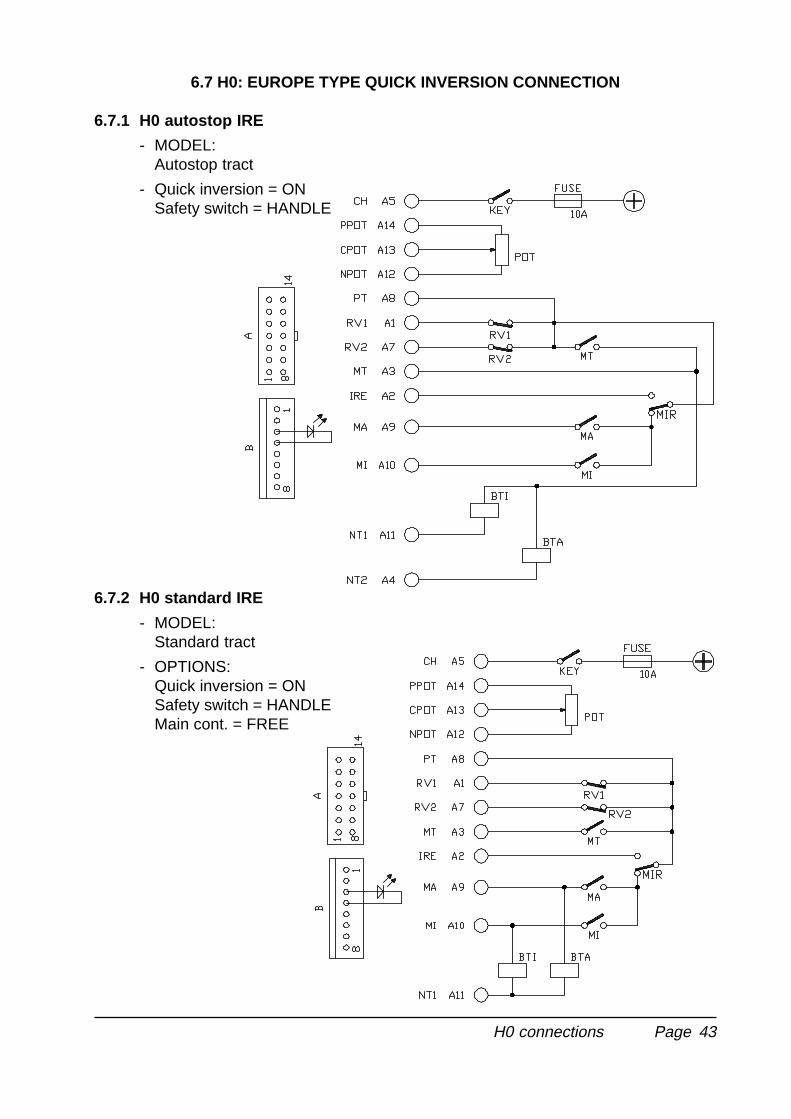
6.7 H0: EUROPE TYPE QUICK INVERSION CONNECTION
6.7.1 H0 autostop IRE
- MODEL:Autostop tract
- Quick inversion = ONSafety switch = HANDLE
6.7.2 H0 standard IRE
- MODEL:Standard tract
- OPTIONS:Quick inversion = ONSafety switch = HANDLEMain cont. = FREE
H0 connections
Page 44
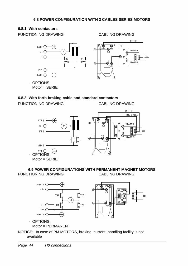
6.8 POWER CONFIGURATION WITH 3 CABLES SERIES MOTORS
6.8.1 With contactors
FUNCTIONING DRAWING CABLING DRAWING
- OPTIONS:Motor = SERIE
6.8.2 With forth braking cable and standard contactors
FUNCTIONING DRAWING CABLING DRAWING
- OPTIONS:Motor = SERIE
6.9 POWER CONFIGURATIONS WITH PERMANENT MAGNET MOTORSFUNCTIONING DRAWING CABLING DRAWING
- OPTIONS:Motor = PERMANENT
NOTICE: In case of PM MOTORS, braking current handling facility is notavailable
H0 connections
Page 45
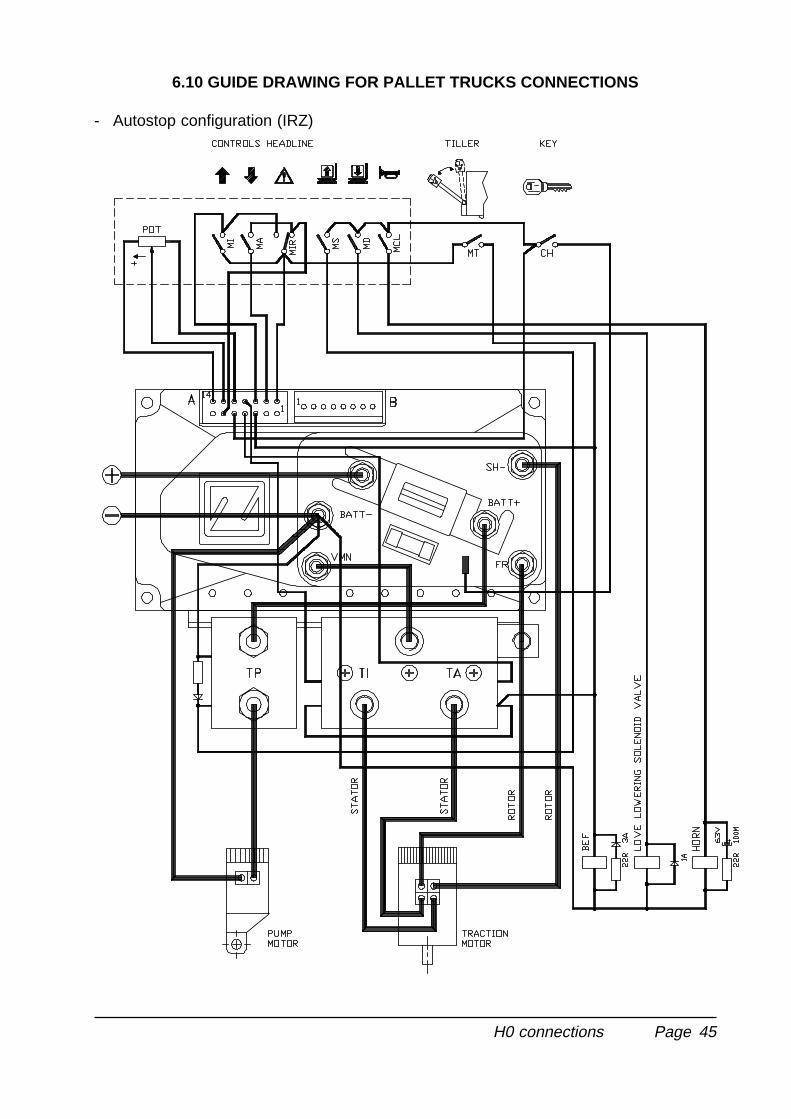
6.10 GUIDE DRAWING FOR PALLET TRUCKS CONNECTIONS
- Autostop configuration (IRZ)
H0 connections
Page 46
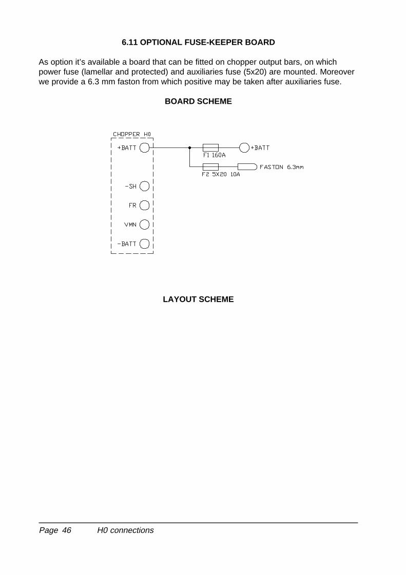
6.11 OPTIONAL FUSE-KEEPER BOARD
As option it’s available a board that can be fitted on chopper output bars, on whichpower fuse (lamellar and protected) and auxiliaries fuse (5x20) are mounted. Moreoverwe provide a 6.3 mm faston from which positive may be taken after auxiliaries fuse.
BOARD SCHEME
LAYOUT SCHEME
H0 connections
Page 47
7 PERIODIC MAINTENANCE TO BE REGULARLY REPEATED
Check wear of electric contacts: they shall be replaced when matchboarding is toostrong and worn-out. Electric contacts shall be checked every 3 months.
Check pedal microswitch: verify with a tester that there is no electric resistance be-tween the contacts by measuring the voltage drop between its terminals. Also the re-lease shall have a firm sound. The pedal microswitch shall be checked every 3months.
Check motor-battery power connections: they shall be in excellent condition as well asthe wires' claddings. Wires shall be checked every 3 months.
Control of the pedal and contactors springs. They shall be able to extend to its fullextention and checked every 3 months.
Check contactors mechanical movements. They shall be frictionfree and not stuck.Mechanical movements of the contactors shall be checked every 3 months.
Checks shall be done only by skilled personnel and, all spare parts shall be original.Installation of this electronic controller shall be done according to the diagrams includedin this manual and any variation shall be done accordingly with the supplier. The sup-plier is not responsible for any problem that rises from using wiring solutions differentfrom the ones suggested on this manual.
Any cause which is visible or realizable by an ordinary technician who periodicallychecks the equipment, that can create damages or defects to the device shall be trans-mitted to the ZAPI's technician or to it's technical commercial network.They will take the responsibility for possible decisions regarding the functioning safetyof the electric vehicle.
DO NOT USE A VEHICLE WITH A
FAULTY ELECTRONIC CONTROLLER
H0
Page 48
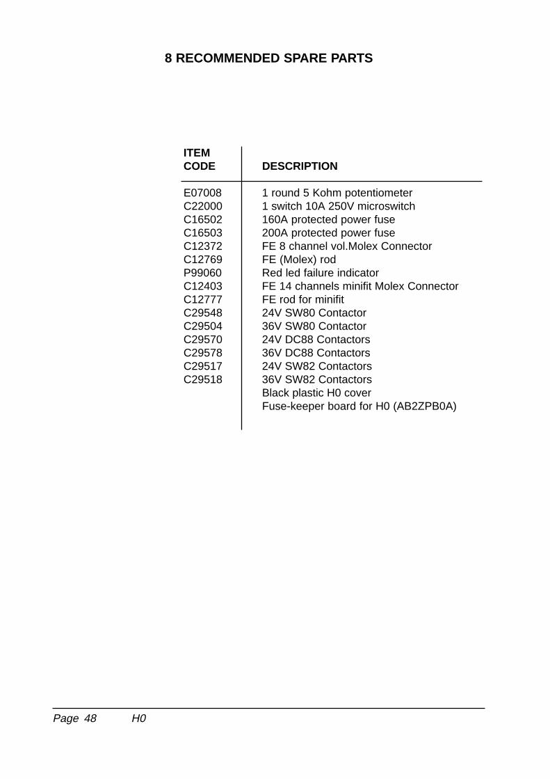
8 RECOMMENDED SPARE PARTS
ITEMCODE DESCRIPTION
E07008 1 round 5 Kohm potentiometerC22000 1 switch 10A 250V microswitchC16502 160A protected power fuseC16503 200A protected power fuseC12372 FE 8 channel vol.Molex ConnectorC12769 FE (Molex) rodP99060 Red led failure indicatorC12403 FE 14 channels minifit Molex ConnectorC12777 FE rod for minifitC29548 24V SW80 ContactorC29504 36V SW80 ContactorC29570 24V DC88 ContactorsC29578 36V DC88 ContactorsC29517 24V SW82 ContactorsC29518 36V SW82 Contactors
Black plastic H0 coverFuse-keeper board for H0 (AB2ZPB0A)
H0

Page 49