Embed Size (px)
Citation preview

ZBPK 13,8V/3A(17Ah)
AWZ 333
• Zasilacz buforowy• Buffer power supply unit • Záložní zdroj• Alimentation tampon
ver. PL/EN/CZ/FR 20060725

PL1. Opis techniczny:
Zasilacz buforowy przeznaczony jest do nieprzerwanego zasilania urządzeń wymagających stabilizowanego napięcia 12V/DC (+/-15%). Zastosowany w urządzeniu liniowy układ stabilizacyjny dostarcza napięcia o mniejszym poziomie szumów i krótszym czasie odpowiedzi na zakłócenie, niż w przypadku stosowania stabilizatora impulsowego. Zasilacz dostarcza napięcia VDC= 12V÷13,8 V DC o wydajności prądowej IMAX=3A. W przypadku zaniku napięcia sieciowego następuje natychmiastowe przełączenie na zasilanie akumulatorowe. Akumulator jest chroniony przed nadmiernym rozładowaniem. Urządzenie wyposażone jest w obwody monitorujące stany pracy oraz wyjścia techniczne sygnalizujące wystąpienie awarii i braku zasilania 230V. Zasilacz zaprojektowany został zgodnie wymogami EMC i LVD Unii Europejskiej.
2. Instalacja:Zasilacz buforowy przeznaczony jest do montażu przez wykwalifikowanego instalatora , posiadający odpowiednie ( wymagane i konieczne dla danego kraju) zezwolenia i uprawnienia do przyłączania( ingerencji) w instalacje 230V/AC oraz instalacje niskonapięciowe.Przed przystąpieniem do instalacji, należy sporządzić bilans obciążenia zasilacza. W czasie normalnej eksploatacji suma prądów pobieranych przez odbiorniki nie może przekroczyć IMAX oraz prąd ładowania akumulatora nie może przekroczyć IACC. Ponieważ zasilacz zaprojektowany jest do pracy ciągłej nie posiada wyłącznika zasilania, dlatego należy zapewnić właściwą ochronę przeciążeniową w obwodzie zasilającym. Należy także poinformować użytkownika o sposobie odłączenia zasilacza od napięcia sieciowego (najczęściej poprzez wydzielenie i oznaczenie odpowiedniego bezpiecznika w skrzynce bezpiecznikowej). Instalacja elektryczna powinna być wykonana według obowiązujących norm i przepisów.
1.Przed przystąpieniem do instalacji należy upewnić się, że napięcie w obwodzie zasilającym 230V jest odłączone.2. Zamontować zasilacz w wybranym miejscu i doprowadzić przewody połączeniowe. 3. Wyjąć bezpiecznik sieciowy zabezpieczający obwód pierwotny transformatora [15]. 4. Przewody zasilania ~230V podłączyć do zacisków AC 230V transformatora [14]. Przewód uziemiający podłączyć do zacisku oznaczonego symbolem uziemienia [16]. Połączenie należy wykonać kablem trójżyłowym (z żółto-zielonym przewodem ochronnym PE). Przewody zasilające należy doprowadzić do odpowiednich zacisków płytki przyłączeniowej [14] [16], poprzez przepust izolacyjny.
Szczególnie starannie należy wykonać obwód ochrony przeciwporażeniowej: żółto-zielony przewód ochronny kabla zasilającego musi być dołączony z jednej strony do zacisku oznaczonego w obudowie zasilacza. Praca zasilacza bez poprawnie wykonanego i sprawnego technicznie obwodu ochrony przeciwporażeniowej jest NIEDOPUSZCZALNA! Grozi uszkodzeniem urządzeń, porażeniem prądem elektrycznym.
5. Podłączyć przewody odbiorników do złączy ‘+’ i ‘-‘ kostki zaciskowej na płytce zasilacza [11]. 6. W razie potrzeby podłączyć przewody od urządzeń ( centrala alarmowa, kontroler, sygnalizator itp.) do wyjść technicznych [11] : - BS wyjście sygnalizujące awarię sieci 230V) Wyjście techniczne BS podczas prawidłowej pracy zasilacza jest odcięte od masy (‘-‘), natomiast w przypadku wystąpienia utraty zasilania 230V AC jest zwierane do masy (‘-‘) po czasie określonym zworkami Z1, Z2 [5] (Tab.3) - AW wyjście sygnalizujące awarie Wyjście techniczne AW podczas prawidłowej pracy zasilacza jest zwarte do masy (‘-‘), natomiast w przypadku wystąpienia jednej z wymienionych przyczyn wyjście zostaje odcięte od masy. 7. Przy pomocy zworek Z3, Z4 [5] określić czas odłączenia akumulatora w przypadku pracy akumulatorowej, gdy napięcie na jego zaciskach spadnie poniżej ~10V. 8. Na kołkach CHARGE [9] określić prąd ładowania akumulatora: IACC = ~0,45A - zworka założona IACC= ~0,9 A - zworka zdjęta 9.Załączyć zasilanie 230V AC i włożyć bezpiecznik sieciowy zabezpieczający obwód pierwotny transformatora [15].Sprawdzić sygnalizację optyczną pracy zasilacza Napięcie wyjściowe nie obciążonego zasilacza wynosi ~13,8V DC.

CZERWONA DIODA• pulsuje - sygnalizuje stan awarii ( Tab.1)
ZIELONA DIODA• świeci - zasilacz zasilany napięciem 230V AC, praca
standardowa• pulsuje - brak napięcia 230V AC, praca z akumulatora
W czasie ładowania akumulatora napięcie może wynosić ~12V÷13,8V DC10. Podłączyć akumulator zgodnie z oznaczeniami [6] (kolorami) . 11. Przy pomocy przycisku STOP [3] włączyć lub wyłączyć dynamiczny test akumulatora (Tab.2)Wyłączenie testu wyłącza również sygnalizację awarii akumulatora na wyjściu AW, lecz nie wyłącza układu chroniącego akumulator przed całkowitym rozładowaniem.12. Wykonać test zasilacza: sygnalizację optyczną [7] [8] (Tab.1), akustyczną [1] (Tab.2), wyjść technicznych poprzez [11] : - odłączenie zasilania 230V AC : sygnalizacja optyczna i akustyczna – natychmiast, wyjście techniczne BS po czasie określonym zworkami Z1, Z2 (Tab.3) - odłączenie akumulatora : sygnalizacja optyczna, akustyczna, wyjście techniczne AW – po wykonaniu testu akumulatora (~ 10 min) 13. Przy pomocy przycisku STOP [3] włączyć lub wyłączyć dynamiczny test akumulatora . Wyłączenie testu wyłącza również sygnalizację awarii akumulatora na wyjściu. 14. Na kołkach ZB [2] określić czy sygnalizacja akustyczna (Tab.2) ma być włączony (zworka założona), czy nie (zworka zdjęta). 15. Po zainstalowaniu i sprawdzeniu poprawności działania zasilacza można zamknąć obudowę.
3. Sygnalizacja pracy zasilaczaUrządzenie wyposażone jest w optyczną i akustyczną sygnalizację stanów pracy
3.1 Sygnalizacja optyczna:
Ilość błysków Typ usterki Przyczyna Uwagi
1 akumulator niesprawny
akumulator nie doładowany, akumulator jest nie
podłączony,przepalony bezpiecznik
akumulatora
sprawdzić poprawność połączenia i bezpiecznik
akumulatora
2 akumulator rozładowany
sygnalizuje obniżenie napięcia akumulatora
poniżej 10Vpodczas pracy bateryjnej
3 za niskie napięcie wyjściowe <10V przeciążone wyjście
usunąć przyczynę odłączyć obciążenie i załączyć
po 30 s
4
za wysokie napięcie wyjściowe
sygnalizowane> 14.5V
uszkodzony stabilizator napięcia, złe ustawienie
potencjometru dostrojczego P1
5 przegrzanie płytki zasilacza temperatura płytki >120°C
Tab.1.

3.2 Sygnalizacja akustyczna:Sytuacje awaryjne sygnalizowane są akustycznie za pomocą buzzera. Częstotliwość i ilość sygnałów uzależniona jest od typu występującej usterki (Tab.2.).Sygnalizację akustyczną można wyłączyć zdejmując zworkę ZB.
Nr Opis Zdarzenie1 1 sygnał co 8s praca bateryjna, brak zasilania 230V AC
2 2 sygnały co 16sniedoładowany akumulator, brak akumulatora
podczas pracy sieciowej, przepalony bezpiecznik akumulatora
3 szybkie sygnałyprzez 3s restart zasilacza
4 12 sygnałów wyłącznie testu akumulatora
5 3 sygnały załączenie testu akumulatora
6 ciągła sygnalizacja awaria, typ sygnalizowany: DIODA CZERWONA
Tab.2.
3.3 Wyjścia techniczne:Zasilacz posiada dwa niezależne wyjścia sygnalizacyjne, umożliwiające przekazanie informacji o braku zasilania AC i awariach systemu.
• AW – wyjście awarii: wyjście typu OC sygnalizujące pojawienie się usterki zasilacza.w stanie normalnym gdy brak awarii wyjście jest zwarte do masy układu, gdy wystąpi awaria wyjście jest rozwierane.
• BS- wyjście brak zasilania 230V/AC: - wyjście typu OC sygnalizuje utratę zasilania 230V AC w stanie normalnym, przy zasilaniu 230V wyjście jest rozwarte w przypadku, utraty zasilania zasilacz załączy wyjście po upływie czasu ustawionego zworkami Z1 Z2.(Tab.3.)
Tab.3
4. Praca z akumulatora.
4.1 Uruchomienie pracy z akumulatora.Czas pracy przy zasilaniu akumulatorowym zależy od pojemności akumulatora, stopnia naładowania oraz prądu obciążenia. Przykładowo, dla typowego w pełni naładowanego akumulatora o pojemności 17Ah i prądu obciążenia 3A maksymalny bezpieczny dla akumulatora czas pracy wynosi ok. 5h.
• Start zasilacza z akumulatora: należy nacisnąć i przytrzymać 5s przycisk START na płycie urządzenia.
• Stop zasilacza z akumulatora: należy nacisnąć i przytrzymać 2s przycisk STOP na płycie urządzenia. Zasilacz odłączy wyjście po ok. 10 sekundach.
4.2 Odłączenie rozładowanego akumulatora.Zasilacz wyposażony jest w układ odłączenia i sygnalizacji rozładowania akumulatora buforowego. Podczas pracy akumulatorowej obniżenie napięcia na zaciskach akumulatora poniżej ~10V spowoduje rozpoczęcie odliczenia czasu do odłączenia akumulatora. Czas odłączenia akumulatora regulowany jest zworkami Z3,Z4. (Tab.4)

Tab.4
4.3 Dynamiczny test akumulatoraCo 10 min zasilacz przeprowadza test akumulatora, poprzez chwilowe obniżenie napięcia na wyjściu i pomiar napięcia na zaciskach akumulatora, awaria jest sygnalizowana w przypadku gdy napięcie będzie niższe niż ~12,2V. Funkcję testu akumulatora w przypadku gdy np. akumulator nie jest podłączony do zasilacza można wyłączyć.
Wyłączenie/załączenie testu: nacisnąć i przytrzymać przez 3s przycisk STOP podczas pracy sieciowej zasilacza.Urządzenie powierdzi akustycznie włączenie lub wyłącznie testu w następujący sposób (Tab.2.).
• testowanie wyłączone 12 dźwięków• testowanie załączone 3 dźwięki
Uwaga:
• załączenie/wyłączenie testu jest pamiętane nawet po odłączeniu urządzenia od zasilania
• wyłączenie testu wyłącza również sygnalizację awarii akumulatora na wyjściu AW, lecz nie wyłącza układu chroniącego akumulator przed całkowitym rozładowaniem.
4.4 Ograniczenie prądu ładowania akumulatoraZasilacz posiada układ automatycznego ograniczenia prądu ładowania akumulatora:
• IACC = ~0,45A - zworka CHARGE założona [9]• IACC = ~0,9A - zworka CHARGE zdjęta [9]
EN 1. Technical description:Buffer power supply unit is designed for the uninterrupted supply of equipment requiring the stabilized voltage of 12V(-/+ 15%). The linear stabilizing system incorporated in the power supply unit provides voltage with less noise and shorter time of fault response, when compared to a pulse stabilizer. The supply unit provides the voltage VDC= 12V÷13,8V DC and the output current of IMAX=3A. In case of power voltage failure, the battery supply is automatically switched on. The battery is protected from the excessive discharge. The unit indicates the operation mode and has the outputs informing about the failure and shortage of power supply 230V. The power supply unit is designed in accordance with the EMC and LVD Directives of European Union.
2. Installation: The buffer power supply unit is to be assembled by a qualified installer, holding the relevant certificates, required and necessary in the particular country for connecting (interfering with) the 230 V AC systems and low-voltage installations. Prior to beginning the installation, the power supply load balance needs to be prepared. In the normal course of operation, the sum of currents used up by the consumers may not exceed IMAX=3A and the battery charging current may not exceed IACC.Because the power supply unit is designed for the continuous operation and is not equipped with ON/OFF switch, the power supply line should have the appropriate overload protection. The user should be informed hot to disconnect the power supply unit from the mains (usually be means of the separate fuse in the fuse-box). The power supply installation should conform to the applicable standards and law.

1. Before installation make sure that the mains 230 V is disconnected.2. Install the power supply at the selected place and evacuate connection wires. 3. Remove the main fuse protecting the transformer primary circuit [15]. 4. Connect the supply conductors ~230V to the terminals of the transformer (AC 230 V). The earthing conductor should be connected to the terminal marked with the grounding symbol. Three-wire cable should be used for the connection (the protective conductor in green-and-yellow). The power conductors should be connected to the appropriate terminals on board [14] [16] and properly insulated.
Particular care must be taken when making the electric shock protection circuit: yellow-green protection conductor of the power cable must be connected from one side to the clamp marked inside the housing of the power supply unit. Operation of the power supply unit without correctly installed and technically functional electric shock protection circuit is NOT ALLOWED! This can lead to damage to the equipment and poses risk of electric shock.
5. Connect the conductors of the consumers to terminals ‘+’ and ‘-‘ of the connection block on the power supply unit board [11]. 6. If necessary, connect the conductors from the equipment (alert central appliance, controller, signalling units, etc.) to technical outputs:
- BS the output signalling the fault to the 230V/ AC In the course of the normal operation of the powerpack, the BS technical output is disconnected from the mass (‘-‘), while in the case of the 230 V AC power failure, it is shortened to the mass (‘-‘) after the time determined by the Z1, Z2 [5] switching pieces (Tab. 3)
- AW output signalling faults The technical output AW during the normal operation of the power supply unit is shortened to the mass (‘-‘), while in the case of the occurrence of any of the above-mentioned events, the output becomes disconnected from the mass. 7. With the switching pieces Z3, Z4 [5] determine the time of disconnecting the battery in the case of battery assisted operation when the voltage on the terminals drops below ~10V. 8. With CHARGE jumper , determine the battery charging current:
IACC = ~0,45A – jumper CHARGE installedIACC = ~0,9A – jumper CHARGE removed
9. Switch on the power supply 230V AC and insert the network fuse protecting the primary circuit of the transformer [15]. Check the optical signalling of the power supply unit operation The output voltage of the unloaded power supply unit is ~13,8V DC.During battery charging, the voltage may be anywhere between ~12V÷13,8V DC.10 .Connect the battery in accordance with the indications [6] (colours). 11. By the means of the STOP [3] pushbutton, enable or disable the battery dynamic test (Tab.2)Disabling the test will also disable signalling the faults to the battery on the AW output, but will not disable the system protecting the battery from entire discharging. 12. Perform the power supply unit test: optical signalling [7] [8] (Tab.1), acoustic signalling [1], technical outputs through:
- disconnecting the 230V AC power supply: optical and acoustic signalling - immediately, technical output BS after the time determined by switching pieces Z1, Z2 (Tab.3) / 3. Indication of operation of the power supply unit /
- disconnecting the battery: optical, acoustic signalling, technical output AW - following performing the battery test (~ 10 min)13. By the means of the STOP [3] pushbutton, enable or disable the battery dynamic test Disabling the test will also disable signalling the fault to the battery on the output. 14. With ZB [2] pins, determine whether the acoustic signalling (Tab.2) is to be enabled (switching piece installed) or disabled (switching piece removed). 15. Following installing and checking the correctness of operation of the power supply, the enclosure may be closed.
3. Indication of operation of the power supply unitThe device is equipped with visual and sound indication of operation.

3.1 Optical indication:
Number of blinks Type of failure Causes Remarks
1 Battery damagedDischarged battery, battery not connected, battery fuse
blown
Check the connection and the fuse of battery
2 Batter dischargedIndicates the drop of the
battery voltage to below 10 V
During operation from battery
3 Output voltage too low < 10V Output overloaded
Remove the condition of the overload and connect
after 30 s
4 Output voltage to high > 14.5V
The voltage stabilizer damaged, incorrect setting of trimming potentiometer
5 Overheating of the power supply unit board
Temperature of board > 120°C
Tab.1.
3.2 Acoustic indication:The buzzer acoustically indicates the failure conditions.The frequency and number of signals depend on the type of failure (Tab.2). The acoustic indication can be disabled by the jumper ZB.
No. Description Event
1 1 signal every 8 s Operation from battery, power supply 230 VAC shortage
2 2 signals every 16 sDischarged battery, no battery during operation from the
mains, battery fuse blown
3 Fast signals during 3s Restart of the power supply unit
4 12 signals Battery test disabled
5 3 signals Battery test enabled
6 Continuous signal Failure, the type of failure indicated by: RED LED
Tab.2.
3.3 Indication outputs.The power supply unit is equipped with indication outputs informing about the power supply shortage and failures.
• AW – failure output: output (OC type) informing about the failures of the power supply unit In the normal state, when there is no failures, the output is closed and it opens if a failure occurs. • BS- Power supply 230 VAC shortage output : output (OC type) informing about the shortageof
power supply 230 VAC in the normal mode, during the operation from 230 VAC the output is open,
RED LED• blinking- indication of failure conditions ( Tab.1)
GREEN LED• lit- power supply unit operated from 230 V/AC, normal
operation • blinking- shortage of power supply 230 V/AC, operation
from battery

in case of power supply shortage the output is activated after the time set by jumpers Z1 Z2 (Tab.3)
Tab.3
4. Operation from battery
4.1 Startup from battery.The operation time from battery depends on the capacity, charge level and load current of battery. For example, the maximum operation time, which is not harmful for the fully charged battery 17 Ah and load current of 3A is about 5h.
• To start the power supply unit from the battery: press and hold Start button on the unit board for 5 s.
• To stop the power supply unit from the battery: press and hold STOP button on the unit board for 2 s.The output will be disabled after about 10 s.
4.2 Disconnection of the discharged batteryThe power supply unit is equipped with the function disconnecting and informing about the discharge of the buffer battery.During the operation from the battery, the decrease of the battery voltage to below 10 V enables the counting of the time for the disconnection of the battery.The battery disconnection time is set by jumpers Z3, Z4. (Tab.4)
Tab.4
4.3 Dynamic test of battery chargeEvery 10 minutes the unit executes the battery test by lowering the input voltage and measuring the voltage on the battery terminals. If the measured voltage is lower than ~12.2V, the failure is indicated.The battery test can be disabled, for example, when the battery was removed from the power supply unit. To enable/disable the battery test: Press and hold the STOP button for 3 s during the operation from the mains. The activation or deactivation of the battery test is indicated as follows:
• test disabled 12 acoustic signals• test enabled 3 acoustic signals
Note: • the activation/deactivation of the test is stored even after the disconnection of the unit
from the mains.• disabling the test will also disable signalling the faults to the battery on the AW output,
but will not disable the system protecting the battery from entire discharging.
4.4 The limitation of the battery charging currentThe unit is equipped with the function for the limitation of the battery charging current
• IACC = ~0,45A - jumper CHARGE set [9]• IACC = ~0,9A - jumper CHARGE removed [9]

CZ1. Technický popis:Záložní zdroj je určen k nepřetržitému napájení zařízení, která vyžadují stabilizované napětí 12V (-/+ 15%). Lineární stabilizační obvod použitý v konstrukcí přístroje dodává napětí o nižší hladině šumu a s kratším časem reakce na rušení ve srovnání s impulsními stabilizátory. Zdroj dodává napětí VDC= 12V÷13,8 V DC o maximální proudové kapacitě IMAX=3A případě ztráty síťového napětí dojde k okamžitému přepnutí na záložní napájení. Akumulátor je chráněn před nadměrným vybitím. Přístroj je vybaven obvody pro monitorování provozních stavů a technickými výstupy signalizujícími poruchy a ztrátu napětí 230V. Zdroj byl zpracován v souladu s požadavky EMC a LVD Evropské unie.
2. Instalace:Stabilizovaný napáječ smí montovat pouze kvalifikovaný instalatér, který má (požadované a v dané zemi nezbytné) povolení a oprávnění pro práci s instalacemi 230V/AC a instalacemi nízkého napětí. Před zahájením instalace je nutné vyhotovit bilanci zatížení napáječe. Během normálního provozu součet proudů napájejících spotřebiče nesmí překročit IMAX=3A a proud nabíjení akumulátoru nesmí překročit IACC.Jelikož je zdroj navržen k nepřetržité práci, nemá vypínač napájení, proto je třeba zajistit v napájecím obvodu příslušnou ochranu proti přetížení. Uživatele je třeba také uvědomit o způsobu odpojení napájení od síťového napětí (nejčastěji označením pojistky v jističové skříňce). Elektrická instalace by měla být provedena podle platných norem a předpisů
1. Dříve, než zahájíte instalaci, ujistěte se, že je v napájecím obvodu vypnuto napětí 230V2. Instalujte napáječ na zvoleném místě a přiveďte spojovací vodiče. 3. Vyjměte síťovou pojistku zabezpečující primární obvod transformátoru. [15]4. Napájecí vodiče ~230V připojte ke svorkám AC 230V transformátoru. Zemnící vodič připojte ke svorce označené symbolem uzemnění. Spojení se provádí trojžilovým kabelem (se žlutozeleným uzemňovacím vodičem PE). Napájecí vodiče přiveďte izolační průchodkou k příslušným svorkám transformátoru [14] [16]
Zvláštní pozornost věnujte obvodu ochrany proti zásahu elektrickým proudem: žlutozelený uzemňovací vodič napájecího kabelu musí být z jedné strany připojen ke svorce označené symbolem ve skříni zdroje. Provoz zdroje bez řádně provedeného a technicky účinného obvodu ochrany proti zásahu elektrickým proudem je NEPŘÍPUSTNÝ! Hrozí nebezpečím poškození zařízení a úrazu elektrickým proudem.
5. Vodiče spotřebičů připojte ke spojům ‘+’ a ‘-‘ svorkovnice na desce napáječe. [11]6. V případě potřeby připojte vodiče zařízení (poplachová centrála, kontrolér, signalizátor apod.) k technickým výstupům:
- BS výstup signalizující poruchu sítě 230V Technický výstup BS je při správné činnosti napáječe odpojený od kostry (‘-‘) a v případě zániku napětí 230V AC je ke kostře připojen (‘-‘) po čase stanoveném svorkami Z1, Z2 [5] (Tab.3).
- AW výstup signalizující poruchu Technický výstup AW je při správné práci napáječe připojen ke kostře (‘-‘) a v případě výskytu některé z uvedených poruch se výstup od kostry odpojí. 7. Pomocí svorek Z3, Z4 [5] určete čas odpojení akumulátoru v případě provozu na akumulátor, pokud napětí na jeho svorkách klesne pod ~10V. 8. Na indikátorech CHARGE [9] určete proud nabíjení akumulátoru:
IACC = ~0,45A – svorka CHARGE zapojená, IACC = ~0,9A – svorka CHARGE rozpojená
9. Zapněte napájení 230V AC a vložte síťovou pojistku zabezpečující primární obvod transformátoru [15]. Zkontrolujte optickou signalizaci práce napáječe.Výstupní napětí nezatíženého napáječe činí ~13,8V DC.Během nabíjení akumulátoru napětí smí činit ~12V÷13,8V DC10 .Připojte akumulátor podle označení [6] (barev). 11. Pomocí tlačítka STOP [3] zapněte nebo vypněte dynamický test akumulátoru (Tab.2)Vypnutí testu vypíná také signalizaci poruchy akumulátoru na výstupu AW, ale nevypíná obvod chránící akumulátor před jeho úplným vybitím. 12. Proveďte test napáječe: optická signalizace [7] [8] (Tab.1), akustická (Tab.2), test technických výstupů [11]:

- odpojením napájení 230V AC: optická a akustická signalizace – okamžitě, technický výstup BS po době určené svorkami Z1, Z2 (Tab.3)
- odpojením akumulátoru: optická signalizace, akustická, technický výstup AW – po provedení testu akumulátoru (~ 10 min).13. Pomocí tlačítka STOP [3] zapněte nebo vypněte dynamický test akumulátoru Vypnutí testu vypíná také signalizaci poruchy akumulátoru na výstupu.14. Na indikátorech ZB [2] určete, zda akustická signalizace (Tab.2) má být zapnutá (svorka spojená), nebo nikoliv (svorka rozpojená). 15. Po instalaci a kontrole správnosti fungování napáječe můžete zavřít skříň.
3. Signalizace provozních stavů zdrojeZařízení je vybaveno optickou a akustickou signalizací provozních stavů .
3.1 Optickou signalizací:
Počet problikn
utíTyp poruchy Příčina Poznámky
1 chyba akumulátoru
Akumulátor není nabitý, akumulátor není připojen,pojistka akumulátoru je
spálená
Zkontrolovat spoje a pojistku akumulátoru
2 akumulátor je vybitý Signalizuje pokles napětí akumulátoru pod 10V Během práce z baterie
3 příliš nízké výstupní napětí <10V Přetížený výstup
Odstraňte příčinu: odpojte zatížení a připojte jej
po 30 s
4příliš vysoké výstupní napětí, signalizováno
> 14.5V
Stabilizátor napětí je poškozen, špatné nastavení dolaďovacího potenciometru
5 přepálená deska zdroje Teplota desky >120°C
Tab.1.
3.2 Akustickou signalizací:Poplašné stavy jsou signalizovány akusticky pomocí buzzeru.Počet a frekvence signálů závisí na typu vzniklé poruchy (Tab.2). Akustickou signalizaci je možné vypnout rozpojením svorky ZB.
ĆERVENÁ DIODA• bliká - signalizuje, že došlo k poruše ( Tab.1)
ZELENÁ DIODA• svítí - zdroj je napájen napětím 230V/AC, pracuje standardně• bliká - ztráta napětí 230V AC, práce z akumulátoru

Č. Popis Událost
1 1 signál každých 8s Práce z baterie, ztráta napětí 230V AC
2 2 signály každých 16s Akumulátor není nabitý, akumulátor není v přístroji během práce z el. sítě, pojistka akumulátoru je spálená
3 rychlé signály po dobu 3s Restart zdroje
4 12 signálů Ukončení testu akumulátoru5 3 signály Zahájení testu akumulátoru6 trvalý signál Porucha, typ signalizovaný : červená DIODA
Tab.2.
3.3 Informační výstupy:Zdroj je vybaven dvěma samostatnými signalizačními výstupy, které předávají informace o ztrátě napětí AC a o poruchách systému.
• AW – výstup poruchy: výstup typu OC signalizuje, že na zdroji došlo k poruše. Za normálního bezporuchového stavu je výstup zkratovaný s kostrou obvodu, dojde-li k poruše, výstup se rozpojí.
• BS- výstup ztráty napětí 230V/AC: výstup typu OC signalizuje ztrátu napájení 230V AC v normálním stavu.Při napájení 230V je výstup rozpojen, v případě ztráty napájení zdroj zapne výstup po uplynutí doby nastavené svorkami Z1 Z2. (Tab.3.)
•
Tab.3
4. Práce z akumulátoru:
4.1 Start práce zdroje z akumulátoruDoba provozu při napájení z akumulátoru závisí na jeho kapacitě, úrovni nabití a zatěžovacím proudu. Například u typického, plně nabitého akumulátoru o kapacitě 17Ah a zatěžovacím proudu 3A maximální pro akumulátor bezpečná provozní doba činí asi 5h.
• Start práce zdroje z akumulátoru: stiskněte a na 5s přidržte tlačítko START na desce přístroje.
• Stop práce zdroje z akumulátoru: stiskněte a na 2s přidržte tlačítko STOP na desce přístroje. Zdroj odpojí výstup po uplynutí asi 10 vteřin.
4.2 Odpojení vybitého akumulátoruZdroj je vybaven obvodem odpojení a signalizace vybití záložního akumulátoru. Pokud během práce akumulátoru napětí na jeho svorkách poklesne pod 10V, začne být odpočítáván čas do odpojení akumulátoru. Doba do odpojení akumulátoru je regulována svorkami Z3 Z4. . (Tab.4)
Tab.4
4.3 Dynamický test nabití akumulátoru:Přístroj provádí každých 10 minut test akumulátoru tak, že dočasně sníží výstupní napětí a proměří napětí na svorkách akumulátoru. Pokud naměří napětí nižší než 12,2 V, bude signalizovat poruchu.

Funkci testování akumulátoru je možné vypnout například v případě, že akumulátor není ke zdroji připojen. Ukončení/zahájení testu: stiskněte a na 3s přidržte tlačítko STOP během práce zdroje ze sítě. Přístroj akusticky potvrdí zahájení nebo ukončení testu takto:
• testování ukončeno 12 zvukových signálů• testování zahájeno 3 zvukové signály
Poznámka: • přístroj si zahájení/ukončení testu zapamatuje i po jeho odpojení od napájení.• vypnutí testu vypíná také signalizaci poruchy akumulátoru na výstupu AW, ale
nevypíná obvod chránící akumulátor před jeho úplným vybitím.
4. 4 Omezení proudu nabíjení akumulátoru.
Zdroj je vybaven obvodem automatického omezení proudu nabíjení akumulátoru• IACC = ~0,45A - svorka CHARGE je sepnutá [9]• IACC = ~0,9A - svorka je od CHARGE rozpojená [9]
FR1. Description technique : L’alimentation tampon est destinée à alimenter sans interruption les appareils demandant une tension stabilisée de 12V (-/+ 15%). Le principe de la régulation linéaire assure une tension de niveau réduit de bruits résiduels et de réponse plus rapide aux perturbations que dans le cas d’un stabilisateur à modulateur d’impulsion. L’alimentation fournit la tension VDC= 12V÷13,8 V/DC d’un rendement de courant de IMAX=3A. Dans le cas d’une coupure de courant dans le secteur il s’opère une commutation immédiate sur l’alimentation de l’appareil par la batterie. La batterie est protégée contre le déchargement trop important. L‘appareil est équipé de circuits de monitoring des états de travail et de sorties techniques signalisant des avaries et l’absence de tension 230V. L’alimentation a été conçue conformément aux exigences EMC et LVD de l’Union Européenne.
2. Installation: L’alimentation tampon est destinée à être montée par un installateur qualifié, possédant les autorisations nécessaires (requises dans le pays donné) pour procéder au branchement (à l’intervention) dans une installation 230V/AC ainsi que dans les installations basse tension.Avant de commencer l’installation il faut faire le bilan de charge prévue pour l’alimentation. Pendant une utilisation normale la somme des courants consommés par les appareils récepteurs ne peut pas dépasser IMAX=3A et le courant de charge de la batterie ne doit pas dépasser IACC.C’est pour ça qu’avant de procéder au câblage il faut bien connaître l’installation électrique du lieu. Pour assurer l’alimentation de l’appareil il faut choisir celui des circuits où l’on est sûr d’avoir de la tension en continu. Il doit être sécurisé avec un fusible spécifique.Puisque l’alimentation ne possède pas d’interrupteur pour la débrancher du courant réseau, il est essentiel d’informer le propriétaire ou l’utilisateur de l‘appareil de la manière de débrancher celui-ci (p. ex. en lui montrant le fusible protégeant le circuit d’alimentation).
1. L’alimentation doit fonctionner en étant branchée en continu sur le courant réseau 230V.2. Monter l’alimentation tampon à l’endroit choisi et amener les câbles de connexion.3. Enlever le fusible protégeant le circuit primaire du transformateur [15].4. Connecter les câbles d’alimentation ~230V aux bornes AC 230V du transformateur [14]. Connecter le fil de terre à la borne marquée du symbole [16]. La connexion doit être faite à l’aide d’un câble trois fils (avec le fils jaune/vert PE). Les câbles d’alimentation doivent être amenés vers les bornes correspondantes du bornier à travers une douille isolée.
Il convient d’apporter un soin tout particulier au circuit de protection contre l’électrocution: le fil jaune/vert du câble d’alimentation doit être connecté d’un côté à la borne marquée du coffret de l’alimentation. Il est INTERDIT de faire fonctionner l’alimentation sans le circuit de protection contre l’électrocution correctement fait et en état de marche.
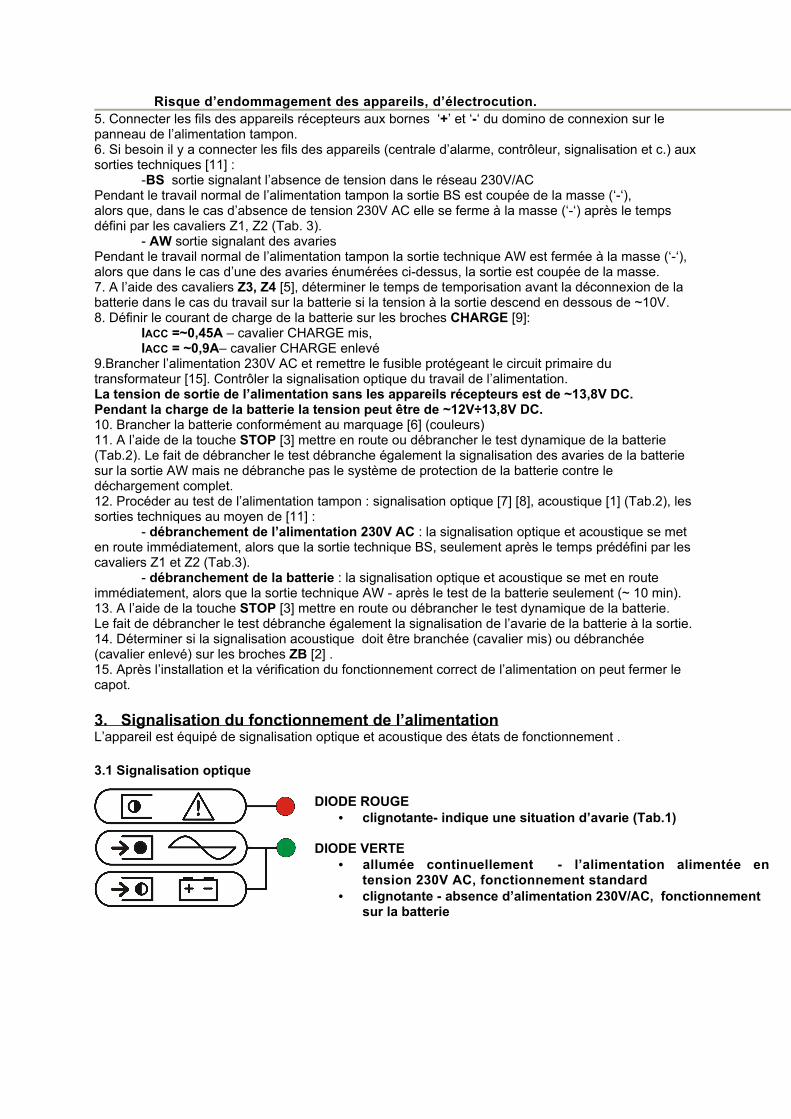
Risque d’endommagement des appareils, d’électrocution.5. Connecter les fils des appareils récepteurs aux bornes ‘+’ et ‘-‘ du domino de connexion sur le panneau de l’alimentation tampon. 6. Si besoin il y a connecter les fils des appareils (centrale d’alarme, contrôleur, signalisation et c.) aux sorties techniques [11] :
-BS sortie signalant l’absence de tension dans le réseau 230V/ACPendant le travail normal de l’alimentation tampon la sortie BS est coupée de la masse (‘-‘),alors que, dans le cas d’absence de tension 230V AC elle se ferme à la masse (‘-‘) après le temps défini par les cavaliers Z1, Z2 (Tab. 3).
- AW sortie signalant des avaries Pendant le travail normal de l’alimentation tampon la sortie technique AW est fermée à la masse (‘-‘), alors que dans le cas d’une des avaries énumérées ci-dessus, la sortie est coupée de la masse.7. A l’aide des cavaliers Z3, Z4 [5], déterminer le temps de temporisation avant la déconnexion de la batterie dans le cas du travail sur la batterie si la tension à la sortie descend en dessous de ~10V. 8. Définir le courant de charge de la batterie sur les broches CHARGE [9]:
IACC =~0,45A – cavalier CHARGE mis,IACC = ~0,9A– cavalier CHARGE enlevé
9.Brancher l’alimentation 230V AC et remettre le fusible protégeant le circuit primaire du transformateur [15]. Contrôler la signalisation optique du travail de l’alimentation.La tension de sortie de l’alimentation sans les appareils récepteurs est de ~13,8V DC.Pendant la charge de la batterie la tension peut être de ~12V÷13,8V DC.10. Brancher la batterie conformément au marquage [6] (couleurs)11. A l’aide de la touche STOP [3] mettre en route ou débrancher le test dynamique de la batterie (Tab.2). Le fait de débrancher le test débranche également la signalisation des avaries de la batterie sur la sortie AW mais ne débranche pas le système de protection de la batterie contre le déchargement complet.12. Procéder au test de l’alimentation tampon : signalisation optique [7] [8], acoustique [1] (Tab.2), les sorties techniques au moyen de [11] :
- débranchement de l’alimentation 230V AC : la signalisation optique et acoustique se met en route immédiatement, alors que la sortie technique BS, seulement après le temps prédéfini par les cavaliers Z1 et Z2 (Tab.3).
- débranchement de la batterie : la signalisation optique et acoustique se met en route immédiatement, alors que la sortie technique AW - après le test de la batterie seulement (~ 10 min).13. A l’aide de la touche STOP [3] mettre en route ou débrancher le test dynamique de la batterie.Le fait de débrancher le test débranche également la signalisation de l’avarie de la batterie à la sortie.14. Déterminer si la signalisation acoustique doit être branchée (cavalier mis) ou débranchée (cavalier enlevé) sur les broches ZB [2] .15. Après l’installation et la vérification du fonctionnement correct de l’alimentation on peut fermer le capot.
3. Signalisation du fonctionnement de l’alimentationL’appareil est équipé de signalisation optique et acoustique des états de fonctionnement .
3.1 Signalisation optique
DIODE ROUGE• clignotante- indique une situation d’avarie (Tab.1)
DIODE VERTE• allumée continuellement - l’alimentation alimentée en
tension 230V AC, fonctionnement standard• clignotante - absence d’alimentation 230V/AC, fonctionnement
sur la batterie

Nombre de
clignotements
Genre d’avarie Cause Commentaires
1 Batterie hors service
Batterie insuffisamment chargée, Batterie n’est
pas connectée,Fusible de la batterie
fondu
Contrôler si le branchement est
correctement faitContrôler le fusible de
la batterie
2 Batterie déchargéeIndique la baisse de la
tension de la batterie en dessous de 10V
Pendant le fonctionnement sur la
batterie
3 Tension de sortie trop basse <10V Sortie surchargée
Eliminer la cause, débrancher la charge et
rebrancher après 30 secondes
4tension de sortie trop
haute> 14.5V
Stabilisateur de tension endommagé, mauvaise
position de potentiomètre de réglage
5 Le panneau de l’alimentation surchauffé
Température de la plaque > 120°C
Tab.1.
3.2 Signalisation acoustique Les situations d’avarie sont signalées acoustiquement à l’aide d’un buzzer.La fréquence et le nombre de signaux dépendent du genre de l’avarie. (Tab.2). La signalisation acoustique peut être débranchée par enlèvement du cavalier ZB.
N° Descrption Evénement
1 1 signal toutes les 8s Fonctionnement sur la batterie, absence d’alimentation 230V AC
2 2 signaux toutes les 16s
Batterie insuffisamment chargée, absence de batterie pendant le fonctionnement sur secteur, fusible de la batterie fondu
3 Série de signaux rapides pendant 3s Redémarrage de l’alimentation
4 12 signaux Arrêt du test de la batterie
5 3 signaux Mise en marche du test de la batterie
6 Signalisation continue Avarie, genre signalisé par la: DIODE ROUGE
Tab.2.
3.3 Sorties d’information:L’alimentation possède deux sorties indépendantes de signalisation permettant la transmission de l’information sur l’absence de l’alimentation AC et sur les avaries du système.
• AW – sortie avarie: sortie de type OC signalisant l’apparition d’une avarie de l’alimentation.En état normal de fonctionnement, sans avarie, la sortie est fermée à la masse du système, quand une avarie survient, la sortie s’ouvre.
• BS- Sortie absence alimentation 230V/AC: - sortie de type OC signalant l’absence de l’alimentation 230V/AC, en état normal de fonctionnement en alimentation 230V, la sortie est ouverte, dans le cas de l’absence d’alimentation, l’alimentation rebranchera la sortie après le temps réglé par les cavaliers Z1 Z2. (Tab.3.)

Tab.3
4. Fonctionnement sur batterie:
4.1 Démarrage du fonctionnement de l’alimentation sur la batterieLe temps de travail sur batterie dépend de la capacité de la batterie, du niveau de sa charge et du courant utilisé par les appareils récepteurs. Par exemple, pour une batterie normale de 17Ah entièrement chargée et le courant servi de 3A, le temps de fonctionnement maximum sûr pour la batterie est d’environ 5h.
• Démarrage du fonctionnement de l’alimentation sur la batterie: appuyer et maintenir pendant 5s la touche START sur le panneau de l’appareil.
• Arrêt du travail de l’alimentation sur batterie: appuyer et maintenir pendant 2s la touche STOP sur le panneau de l’appareil. L’alimentation débranchera la sortie après environ 10 secondes.
4.2 Débranchement de la batterie déchargée.L’alimentation est équipée d’un dispositif de débranchement et de signalisation du déchargement de la batterie tampon. Pendant le fonctionnement de l’alimentation sur la batterie une baisse de tension sur les bornes de la batterie en dessous de ~10V provoquera le début du décompte du temps restant jusqu’au débranchement de la batterie. La durée de temporisation jusqu’au débranchement de la batterie est réglée à l’aide des cavaliers Z3 Z4. (Tab.4)
Tab.4
4.3 Test dynamique de charge de la batterie:Toutes les 10 min l’appareil procède à un test de la batterie par une baisse momentanée de la tension de sortie et la mesure de la tension sur les bornes de la batterie, une avarie est signalée si la tension mesurée est en dessous de 12,2V. La fonction de test peut être débranchée, par exemple quand la batterie n’est pas branchée à l’alimentation.
Arrêt/marche du test: appuyer et maintenir pendant 3s la touche STOP pendant le fonctionnement de l’alimentation sur secteur. L’appareil confirmera acoustiquement la mise marche ou l’arrêt du test de manière suivante:
• test débranché 12 sons• test branché 3 sons
Attention: • marche/arrêt du test est mémorisé même après le débranchement de l’alimentation de
l’appareil • le fait de débrancher le test débranche également la signalisation des avaries de la
batterie sur la sortie AW mais ne débranche pas le système de protection de la batterie contre le déchargement complet.
4.4 Limitation du courant de charge de la batterieL’alimentation est équipée d’un dispositif de limitation automatique du courant de charge de la batterie jusqu’à la valeur :
• IACC = ~0,45A - cavalier CHARGE mis [9]• IACC = ~0,9A - absence de cavalier sur CHARGE [9]

fig. 1

No.[fig.1] PL EN CZ FR
[1] sygnalizacja akustyczna acousticindication
akustickousignalizací signalisation acoustique
[2]ZB zworka ZB jumper ZB svorky ZB cavalier
[3] STOP przycisk STOP button STOP tlačítko STOP touche
[4] START przycisk START button START tlačítko START touche
[5] Z1, Z2, Z3, Z4zworki Z1, Z2, Z3, Z4 jumpers Z1, Z2, Z3, Z4
svorky Z1, Z2, Z3, Z4 cavaliers
[6] WYJŚCIAakumulatora
OUTPUTSbartery
VÝSTUPYakumulátoru
SORTIESbatterie
[7] CZERWONA DIODAsygnalizacja optyczna
RED LEDoptical indication
ĆERVENÁ DIODAoptickou signalizací
DIODE ROUGEsignalisation optique
[8] ZIELONA DIODAsygnalizacja optyczna
GREEN LEDoptical indication
ZELENÁ DIODAoptickou signalizací
DIODE VERTEsignalisation optique
[9] 16V ACzłącze
16V ACterminals
16V ACsvorky
16V ACcavaliers
[10] CHARGEzworka
CHARGEjumper
CHARGEsvorky
CHARGEcavalier
[11] WYJŚCIAzłącze (Tab.6)
OUTPUTSterminals (Tab.6)
VÝSTUPYsvorky (Tab.6)
SORTIEScavaliers (Tab.6)
[12] P1regulacja napięcia
P1voltage adjust
P1regulace výstupniho
napăti
P1régulation de la tension de
sortie
[13]F1
bezpiecznik w obwodzie akumulatora
F1fuse in the battery circuit
F1pojistka v obvodu
akumulátoru
F1fusible dans le circuit de la
batterie
[14] 230V – 0Vzłącze zasil. 230V/AC
230V – 0Vterminals 230V/AC
230V – 0Vsvorky 230V/AC
230V – 0Vcavaliers 230V/AC
[15]F2
bezpiecznik w obwodzie pierwotnym transformatora
F2fuse in the primary
windings of the transformer
F2pojistka v prvotním obvodu
transformátoru
F2fusible dans le circuit
primaire du transformateur
[16] złącze(z żółto-zielonym
przewodem ochronnym PE)
terminals(the protective
conductor in green-and-yellow)
svorky(se žlutozeleným
uzemňovacím vodičem PE)
cavalier(avec le fils
jaune/vert PE)
Tab.5
[11] PL EN CZ FR+ OUT- OUT
‘+’ wyjście +Vcc‘-‘ wyjście 0V
‘+’ output +Vcc‘-‘ output 0V
‘+’výstupní napětí +Vcc‘-‘výstupní napětí 0V
‘+’ sortie +Vcc‘-‘ sortie 0V
AWwyjście techniczne awarii
- NCtypu OC
failure output- NCtype OC
technický výstup poruchy- NC
typu OC
sortie technique de l’avarie- NC
type OC
BSwyjście techniczne braku
230V/AC - NOtypu OC
power supply 230V/AC shortage output- NO
type OC
technický výstup ztráty 230V/AC - NO, typu OC
sortie technique absence 230V/AC- NO, type OC
TAMPERstyki wyłącznika
antysabotażowego - NC tamper contact- NC protisabotážní kontakty - NC
connexion de l’interrupteur anti-
sabotage- NCTab.6

PARAMETRYTECHNICZNE
TECHNICALDATA
TECHNICKÉPARAMETRY
LES PARAMÉTRES TECHNIQUES
Napięcie zasilania Power supply voltage Napájecí napětí Tension d’entrée 230V/AC 50Hz
(-/+15%)
Transformator Transformer Transformátor Transformateur TR 80VA(EN-61558-2-6)
Napięcie wyjściowe OUT Vcc –min/max
Output voltage OUT Vcc-
min/max
Výstupní napětí OUT Vcc –min/max
Tension de sortie OUT Vcc- min/max
12V÷13,8V/DC13,8V/DC – nom.(13,3V/DC@2A)
Prąd wyjściowy OUT - max
Output current OUT - max
Proud výstupní OUT - max
Courant de sortie OUT - maxi
Imax=3A(const.)
Prąd ładowania akumulatora Iacc –
max/max
Battery charging current Iacc –
max/max
Proud nabíjení akumulátoru Iacc –
max/max
Courant de charge de la batterie Iacc -
max/max
Iacc=~450mA/~900
mA
F2 bezpiecznik w obwodzie
pierwotnym transformatora
F2 fuse in the primary windings of
the transformer
F2 pojistka v prvotním obvodu transformátoru
F2 fusible dans le circuit primaire du
transformateur
T 1A(250V)
Prąd obwodu pierwotnego
transformatora - max
Current of the primary windings of
the transformer - max
Proud v prvotním obvodu
transformátoru - max
Courant du circuit primaire du
transformateur - max
~ 400 mA
Zabezpieczenie termiczne
transformatora
Thermal protection of the transformer
Tepelná ochrana transformátoru
Protection thermique du
transformateur130 ºC
F1 bezpiecznik w obwodzie
akumulatora
F1 fuse in the battery circuit
F1 pojistka v obvodu
akumulátoru
F1 fusible dans le circuit de la batterie F 5A
Akumulator Battery Akumulátor Batterie 17Ah/12V
Obciążalność wyjść technicznychAW, BS - max
Technical outputs current
AW, BS - max
Proudová zatížitelnost
technických výstupůAW, BS - max
Courant des sorties techniques
AW, BS -max
50mA@30V(max.)OC
Obciążalność wyjścia TAMPER-
max
Output currentTAMPER - max
Proudová zatížitelnost
výstupů TAMPER - max
Courant des sortie TAMPER - max 500mA@30V
Obudowa IP Casing IP Krytu IP Boitier IP IP 20
Temperatura pracy Operating temperature Provozní teplota Température de
travail -10ºC÷45ºC
Wilgotność względna RH –
max.
Relative humidityRH –max.
Relativni vlhkost RH – max
Humidité RH -max 93 [%]
Wymiary(szer x wys x głeb)
Dimensions(w x h xd )
Rozměry(š x v x h)
Dimensions(larg.x haut. x
profon)
235 x 305 x 98(90+8)
[-/+2] [mm]Waga Weight Hmotnost Poids 3.3 [kg]

PRODUCENT / PRODUCER/ VÝROBCE / PRODUCENT
Pulsar K.Bogusz Sp.j. Siedlec 150,
32-744 Łapczyca, PolandTel. (+48) 14-610-19-40, Fax. (+48) 14-610-19-50
e-mail: [email protected], [email protected]:// www.pulsarspj.com.pl
GWARANCJA :24 miesiące od daty sprzedaży , 36 miesięcy od daty produkcji.
GWARANCJA WAŻNA tylko po okazaniu faktury sprzedaży, której dotyczy reklamacja
GUARANTEE:24 months from the date of sale, 36 months from the date of production.
THE GUARANTEE IS VALID only upon presenting the sale invoice for the unit for which the claim is made.
ZÁRUKA:24 měsíců od data prodeje, 36 měsíců od data výroby.
ZÁRUKA PLATÍ pouze při současném předložení faktury potvrzující prodej, ke kterému se reklamace váže.
GARANTIE:24 mois depuis la date d’achat, 36 mois depuis la date de fabrication.
GARANTIE VALABLE uniquement avec la facture de vente du produit faisant l’objet de la réclamation.


![PSBS 10A12D PSBS 13,8V/10A/40Ah - pulsar.pl - Edition 1... · Deep discharge protection UVP U < 10,0V ... Enclosure dimensions 350 x 445 x 178 (345 x ... [mm] (+/- 2) Fixing 315 x](https://img.pdfslide.tips/doc/110x75/5b8c5b4f09d3f24a638cd0e8/psbs-10a12d-psbs-138v10a40ah-edition-1-deep-discharge-protection-uvp.jpg)