Embed Size (px)
Citation preview

1ELAFLEX - Gummi Ehlers GmbH · 22525 Hamburg · Germany Schnackenburgallee 121 · Tel. +49 40 - 540 00 5-0 · Fax +49 40 - 540 00 5-67
FLUGZEUG-ZAPFVENTIL, NICHT AUTOMATISCH Deutsch
MONTAGE- UND BEDIENUNGSANLEITUNG Seite 2
AVIATION FUEL NOZZLE, NON-AUTOMATIC English
INSTALLATION AND OPERATING INFORMATION page 8
3.2015
ZVF 50

2 3
BESCHREIBUNGDas ZVF 50 ist ein nicht automatisches Hochleistungs-Zapfventil für die Oberflügelbetankung von Flugzeugen und Hubschraubern mit Flugtreibstoffen, zum Beispiel JET A, JET A-1 (ASTM D1655), JP 8, F 34, F 35, F 37 (MIL-T-83133) und AVGAS 80, AVGAS 100, AVGAS 100LL (ASTM D910).
Die Konstruktion des Zapfventils entspricht den Anforderungen von JIG 1, ATA Spec. 103, PEI / RP 1300-13 und SAE AS 1852.
Vorgesehene Einsatzbedingungen:
Nennweite: DN 50 mm ( 2" ) Durchflussrate: empfohlen bis 400 l / min. Betriebsdruck max: 10 bar (Nenndruck) Einsatztemperatur: Standard: - 25° C bis + 55° C 'LT' - Type: - 40° C bis + 55° C Betrieb: Standard: für Druckbetrieb 'L' - Type : auch für Rücksaugung geeignet
Jedes Zapfventil wird vor Auslieferung auf Betriebstauglichkeit geprüft, einer Funktionsprüfung unterzogen und mit einer Seriennummer versehen.
INSTALLATIONDas ZVF 50 wird betriebsfertig geliefert. Nach ordnungsgemäßer Montage an der Schlauchleitung durch fachkundiges Personal sind folgende Schritte durchzuführen:
1. Bei geringem Pumpendruck ( 0,5 – 1 bar) • Prüfung der Dichtheit aller Komponenten. • Entlüftung und Spülung des ZVF 50 Innenraumes durch mehrfaches Betätigen des
Schalthebels. ACHTUNG : Geeigneten Auffangbehälter verwenden.
2. Bei maximal vorgesehenem Druck • Prüfung der Dichtheit aller Komponenten. • Erneute Spülung des ZVF 50 Innenraumes durch mehrfaches Betätigen des Schalthebels.
ACHTUNG : Geeigneten Auffangbehälter verwenden.
Tragen Sie grundsätzlich geeignete Schutzkleidung.
BEDIENUNGFür den Betrieb des ZVF 50 sind die jeweils gültigen Standards und Regelwerke zu berücksichtigen.
Bei eingeschalteter Pumpe wird die Abgabe durch Ziehen des Schalthebels begonnen. Die Durchflussleistung des ZVF 50 lässt sich stufenlos und einfach regulieren. Zu Beginn und Beendigung des Betankungsvorgangs – insbesondere bei ungünstig platzierten oder geformten Einfüllstutzen – wird eine Abgabe mit reduzierter Leisung empfohlen um ein Zurückspritzen von Kraftstoff aus dem Einfüllstutzen sicher zu vermeiden.
Die erforderliche Aufhaltekraft des Schalthebels ist geringer als bei vergleichbaren Ventilen. Bei Nutzung der LeverAssist ® Aufhaltehilfe ( Seite 4 ) wird die notwendige Aufhaltekraft um weitere 75 % reduziert.
Das ZVF 50 schließt selbsttätig beim Loslassen des Schalthebels.
Protektorring
1
2
Auslaufrohr drehen : Das Auslaufrohr ist drehbar, um das Ventil bei JET-Betankung an die Ausrichtung des Stut-zens anzupassen. Hierzu Protektorring gegen Uhrzeigersinn lösen, Auslaufrohr in gewünschte Position drehen, anschließend Protektorring wieder handfest anziehen.
Auslaufrohr wechseln : Protektorring muss handfest angezogen sein. Aus lauf rohr gegen Uhrzeigersinn herausschrau-ben und gegen gewünschte Größe oder Typ austauschen. Vollständiges, handfestes Ein-schrauben genügt für ausreichende Dichtheit. ACHTUNG: gültige Vorschriften beachten. Zur Vermeidung von Fehlbetankungen nur die dem Kraftstoff zugeordneten Auslauf-rohre verwenden.
Inspektion des Siebes :Der Protektorring muss handfest angezogen sein. Auslaufrohr herausschrauben. Zur Kont-rolle hilft es, das Sieb gegen das Licht zu betrachten. Falls eine genaue Kontrolle nicht möglich oder eine Reinigung erforderlich ist wird das Sieb ausgebaut – siehe rechts.
Ausbau des Siebes :Protektorring lösen und herausschrauben. Das Sieb lässt sich nun aus der Aufnahme heraus-nehmen und durch Ausblasen mit Luft bzw. im Reinigungsbad säubern. Bei Beschädigungen Sieb ES 418.1 ersetzen. Die Montage erfolgt handfest, in umgekehrter Reihenfolge.
AUSLAUFROHR / SIEB
Sieb ES 418.1 (160µm / 100 mesh)

4 5
Die LeverAssist® Aufhaltehilfe für den Schalthebel reduziert die notwendige Aufhaltekraft um 75 %. Lange Tankvorgänge werden dadurch komfortabler. Die 'Totmannfunktion' bleibt voll erhalten. Es sind drei Stufen wählbar: niedrige, mittlere und volle Leistung.Dazu Schalthebel auf gewünschte Leis-tung ziehen, LeverAssist mit dem klei-nen Finger betätigen und halten. Zug auf Schalthebel verringern, LeverAssist da - bei weiter halten.
Einsatz der Erdungskabelgarnitur EKG: Anbringung an der Befestigungsöse unterhalb des Zapfventilgehäuses. Das Aufwickeln des Kabels erfolgt um den Protektorring.
NUTZUNG DER AUFHALTEHILFE
s
s
LeverAssist®
ERDUNGSKABEL / GUMMIKAPPENGARNITUR
Einsatz der Gummikappengarnitur GKG: An bringung an einer 'Speiche' des Protektorrin-ges. Beim Wechsel des Auslaufrohres ist auch die Gummikappengarnitur zu wechseln.
6 7
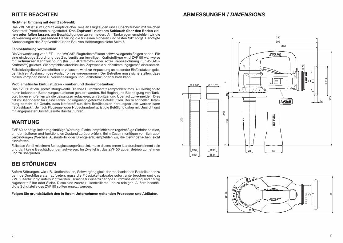
BITTE BEACHTENRichtiger Umgang mit dem Zapfventil:Das ZVF 50 ist zum Schutz empfindlicher Teile an Flugzeugen und Hubschraubern mit weichen Kunststoff-Protektoren ausgestattet. Das Zapfventil nicht am Schlauch über den Boden zie-hen oder fallen lassen, um Beschädigungen zu vermeiden. Am Tankwagen empfehlen wir die Verwendung einer passenden Halterung die für einen sicheren und festen Sitz sorgt. Benötigte Abmessungen des Zapfventils für den Bau von Halterungen siehe Seite 7.
Fehlbetankung vermeiden:Die Verwechslung von 'JET'- und 'AVGAS'-Flugtreibstoff kann schwerwiegende Folgen haben. Für eine eindeutige Zuordnung des Zapfventils zur jeweiligen Kraftstofftype wird ZVF 50 wahlweise mit schwarzer Kennzeichnung (für JET-Kraftstoffe) oder roter Kennzeichnung (für AVGAS- Kraftstoffe) geliefert. Wir empfehlen ausdrücklich, Zapfventile nur bestimmungsgemäß einzusetzen. Falls lokal geltende Vorschriften es zulassen, wird zur Anpassung an besonder Einfüllstutzen gele-gentlich ein Austausch des Auslaufrohres vorgenommen. Der Betreiber muss sicherstellen, dass dieses Vorgehen nicht zu Verwechslungen und Fehlbetankungen führen kann.
Problematische Einfüllstutzen - sauber und dosiert betanken:Das ZVF 50 ist ein Hochleistungsventil. Die volle Durchflussrate ( empfohlen: max. 400 l/min ) sollte nur in bekannten Betankungssituationen genutzt werden. Bei Beginn und Beendigung von Tank-vorgängen empfehlen wir die Leisung zu reduzieren, um Spritzer und Überlauf zu vermeiden. Dies gilt im Besonderen für kleine Tanks und ungünstig geformte Befüllstutzen. Bei zu schneller Betan-kung besteht die Gefahr, dass Kraftstoff aus dem Befüllstutzen herausgedrückt werden kann ('Splashback'). Je nach Flugzeug- oder Hubschraubertyp ist die Befüllung daher mit Umsicht und mit angepasster Durchflussrate durchzuführen.
WARTUNGZVF 50 benötigt keine regelmäßige Wartung. Elaflex empfiehlt eine regelmäßige Sichtinspektion, um den äußeren und funktionalen Zustand zu überprüfen. Beim Zusammenfügen von Schraub-verbindungen ( Wechsel Auslaufrohr oder Drehgelenk ) empfehlen wir, die Gewindeflächen leicht einzufetten.Falls das Ventil mit einem Schauglas ausgerüstet ist, muss dieses immer klar durchscheinend sein und darf keine Beschädigungen aufweisen. Im Zweifel ist das ZVF 50 außer Betrieb zu nehmen und zu überprüfen.
BEI STÖRUNGENSofern Störungen, wie z.B. Undichtheiten, Schwergängigkeit der mechanischen Bauteile oder zu geringe Durchflussraten auftreten, muss die Flüssigkeitsabgabe sofort unterbrochen und das ZVF 50 fachkundig untersucht werden. Ursache für eine zu geringe Durchflussleistung sind häufig zugesetzte Filter oder Siebe. Diese sind zuerst zu kontrollieren und zu reinigen. Äußere beschä-digte Schutzteile des ZVF 50 sollten ersetzt werden.
Folgen Sie grundsätzlich den in Ihrem Unternehmen geltenden Prozessen und Abläufen.
ABMESSUNGEN / DIMENSIONS
38�
32�
44�
38�
305330
115
�
14 363
186
18
70�
28 68
248
262
142
136
Ø
200
G 1 1/2" G 1 1/2"

8 9
DESCRIPTIONThe ZVF 50 is a manual (non-automatic) high flow nozzle for overwing and helicopter refuelling for all types of aviation fuels, such as JET A, JET A-1 (ASTM D1655), JP 8, F 34, F 35, F 37 (MIL-T-83133) and AVGAS 80, AVGAS 100, AVGAS 100LL (ASTM D910).
The construction of the nozzle fulfills the requirements of JIG 1, ATA Spec. 103, PEI / RP 1300-13 and SAE AS 1852.
Operating Conditions:
Nominal size: DN 50 mm ( 2" ) Flow rate: Suggested up to 400 l / min. (85 IGM) Working pressure max. 10 bar (Nominal Pressure PN 10) Operation temperature range: Standard type: - 25° C up to + 55° C 'LT' type: - 40° C up to + 55° C Operation: Standard type: for pressure service 'L' type : also suitable for defuelling
Before leaving the factory, each nozzle is subjected to a functional test and validated with a serial number.
INSTALLATIONThe ZVF 50 is delivered ready for use. Nozzles should only be installed and tested by competent personnel. Applicable laws, regulations and Codes of Practice have to be followed. After connection of the hose assembly to the nozzle, please follow the following steps:
1. With low pump pressure ( 0,5 – 1 bar) • check tightness of all components. • vent and flush the inner parts of the nozzle by pulling the lever several times.
Note : Use suitable receiving container.
2. With maximum pump pressure intended for operation • check tightness of all components. • vent and flush the inner parts of the nozzle again, by pulling the lever several times.
Note : Use suitable receiving container.
Always wear suitable protective clothing.
OPERATIONFor the operation of the ZVF 50, local laws and code of practice must be followed.
When the pump is running, fuelling is started by pulling the nozzle lever. The flow rate of the ZVF 50 can be regulated smoothly and easily. At the beginning and towards the end of the refuelling ope-ration – especially when dealing with awkwardly located or shaped filler openings – a reduced flow rate is advisable to safely avoid fuel splashbacks from the filler opening.
The necessary hold-open force of the lever is lower than with comparable nozzles. When using the LeverAssist ® hold-open aid ( page 10 ) further reduces the necessary hold-open force by 75 %.
To end fuelling, release the lever of the ZVF 50.
Protector Ring
1
2
Rotating spout : The spout can be rotated to the required posi-tion. This is useful for JET refuelling, to locate the nozzle to the filler opening. Loosen protector ring anti-clockwise, rotate spout to required position and fix protector ring hand-tight.
Change spout : Protector ring must be fixed hand-tight. Unscrew spout anti-clockwise and substitute with requi-red new type or size. Hand-tight connection is sufficient for tight connection. NOTE: follow local regulations in place. To avoid misfuelling only spouts should be used which are assigned for the used fuel.
Inspection of strainer :Protector ring must be fixed hand-tight. Unscrew spout anti-clockwise. Inspect the strainer while holding it against the light. If a proper inspection is not possible or cleaning is necessary, the strainer is removed – see remarks on right hand side.
Cleaning of strainer:Loosen and unscrew protector ring. The strainer can now be taken out of its seat. Clean by blowing out with air or in a suitable cleaning bath. If the strainer ES 418.1 is damaged, replace. Re-assembling in opposite order, hand-tight.
SPOUT / STRAINER
Strainer ES 418.1 (160µm / 100 mesh)
10 11
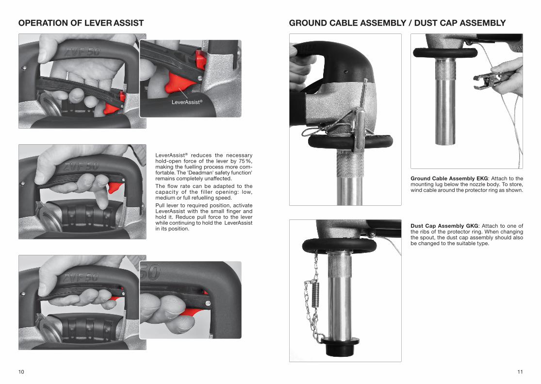
LeverAssist® reduces the necessary hold-open force of the lever by 75 %, making the fuelling process more com-fortable. The 'Deadman' safety function' remains completely unaffected. The flow rate can be adapted to the capacity of the filler opening: low, medium or full refuelling speed.Pull lever to required position, activate LeverAssist with the small finger and hold it. Reduce pull force to the lever while continuing to hold the LeverAssist in its position.
Ground Cable Assembly EKG: Attach to the mounting lug below the nozzle body. To store, wind cable around the protector ring as shown.
OPERATION OF LEVER ASSIST
s
s
LeverAssist®
GROUND CABLE ASSEMBLY / DUST CAP ASSEMBLY
Dust Cap Assembly GKG: Attach to one of the ribs of the protector ring. When changing the spout, the dust cap assembly should also be changed to the suitable type.

12
PLEASE NOTEProper Handling of the Nozzle:The ZVF 50 is equipped with various external soft plastic parts. These are intended to protect the aircraft. To prevent damage to the nozzle, it should not be pulled along the ground or dropped to the ground. When not in use the nozzle should be stoved away in a suitable device (nozzle holder). For the construction of such a device see ZVF 50 dimensions on page 7.
Avoid Misfuelling:Refuelling aircraft with the wrong type of fuel can lead to serious consequences. To clearly allocate the nozzle to the used fuel type, ZVF 50 are available either as black marked 'JET' or red marked 'AVGAS' type. We strongly advise to use aviation nozzles only for the designated fuel type. If local regulations permit, the spout type can be temporarily changed to adopt to special filler openings. It is the responsibility of the operator to safeguard that these actions may never lead to any confusion or to misfuelling with the wrong fuel type.
Problematic Filler Openings - Clean and Well Regulated Refuelling:The ZVF 50 is a high flow nozzle. Adjust the pump performance to a max. flow rate of 400 l/min.The max. flow rate should only be chosen in already known refuelling configurations. At the begin-ning and towards the end of the refuelling operation – especially when dealing with small tanks and awkwardly located or shaped filler openings – a reduced flow rate is advisable to safely avoid fuel splashbacks from the filler opening. Depending on the type of aircraft, the fuelling shall always be done with a suitable flow rate.
MAINTENANCEZVF 50 nozzles do not require regular maintenance. Elaflex suggests recurring visual inspections to check the external and functional condition of the nozzle. When connecting threaded parts ( substitution of spout or swivel ) we suggest to slightly lubricate the thread surface.If the nozzle is equipped with a sight glass, it must always appear clearly transparent and not show any sign of damage. If in doubt, the nozzle shall be put out of service for an inspection by com-petent personnell.
MALFUNCTIONIf malfunctions such as leakage, sluggishness of mechanical parts or too flow rates occur, fuelling should be immediately stopped, and the nozzle should be inspected by competent personnell. Cause for a low flow rate often are clogged strainers or filters. These should be checked respectively cleaned first. Damaged external protecion parts of the ZVF 50 should be replaced.
Always follow your companys laid down process and procedures.


![Verbrauchskennwerte Melken, Reinigen, Leerlauf0 50 1001 50 2002 50 3003 50 4004 50 5005 50 6006 50 Energiebedar f [Wh] Kompressor/Kältetrockner AMS Rest Vakuumpumpe Boiler Grundlast](https://img.pdfslide.tips/doc/110x75/6097c5ce13808c50f13e6dd4/verbrauchskennwerte-melken-reinigen-leerlauf-0-50-1001-50-2002-50-3003-50-4004.jpg)