1
Supporting Information for:
A key concept of utilization of both non-Grignard magnesium chloride and imide salts for rechargeable
Mg battery electrolytes
Toshihiko Mandai,†,* Yasuhiro Akita,† Shunsuke Yagi,‡ Minato Egashira,§
Hirokazu Munakata,† Kiyoshi Kanamura†
†Department of Applied Chemistry, Graduate School of Urban Environmental Sciences, Tokyo
Metropolitan University, 1-1 Minami-Osawa, Hachioji, Tokyo 192-0397, Japan
‡Institute of Industrial Science, The University of Tokyo, 4-6-1 Komaba, Meguro-ku, Tokyo 153-
8505, Japan
§College of Bioresource Science, Nihon University, 1866 Kameino, Fujisawa, Kanagawa, 252-0880,
Japan
CORRESPONDING AUTHOR FOOTNOTES
Telephone:+81-42-677-2826, E-mail: [email protected]
Electronic Supplementary Material (ESI) for Journal of Materials Chemistry A.This journal is © The Royal Society of Chemistry 2017
2
Experimental
Materials and electrolyte preparation
Ethylmagnesium chloride (EtMgCl; ca. 18% in tetrahydrofuran, ca. 2 mol dm−3), anhydrous
ethanol, 1-propanol, ethylene glycol monomethyl ether, ethylene glycol, 2-(dimethylamino)ethanol,
diethylamine, bis(2-methoxyethyl)amine, diphenylamine, N-(2-methoxyethyl)methylamine, and
silver nitrate (AgNO3) were all purchased from Tokyo Chemical Industry Co., Ltd. Anhydrous
tetrahydrofuran (THF) and triglyme (G3; for electrochemistry) were obtained from Wako Pure
Chemical Industries, Ltd., and Kanto Chemical Co., Inc., respectively. Battery grade magnesium
bis(trifluoromethanesulfonyl)imide (Mg(TFSI)2) was purchased from Kishida Chemical Co., Ltd. All
purchased chemicals were used without further purification.
The studied magnesium chloride salts were all synthesized by slowly adding the appropriate
amount of alcohols or amines dropwise into EtMgCl/THF in an open beaker and stirring for 30 minutes
inside an Ar-filled glovebox (< 1 ppm H2O, < 1 ppm O2). The reaction proceeds immediately after
mixing as confirmed by the rapid evolution of ethane gas via a hydrogen metal exchange reaction.
Complete removal of the THF solvent and starting materials by slow evaporation at 60 ºC overnight
and subsequent vacuum drying at 80 ºC for several days yielded the desired salts as light-grey powders.
The ternary electrolyte solutions were prepared by mixing stoichiometric amounts of each component
and vigorously stirring at 100 ºC inside the glovebox to obtain a desired homogeneous clear liquid.
3
Measurements
The transport properties of the selected electrolyte solutions were characterized with respect to
their ionic conductivity and density (concentration). The ionic conductivities (σ) of O1/Mg(TFSI)2/G3
and EtMgCl/Mg(TFSI)2/G3 were determined by the complex impedance method using an
electrochemical analyzer (ALS 760B, HCH Instrument) in the frequency range of 1 to 100 kHz with
a sinusoidal alternating voltage amplitude of 10 mV root-mean-square (rms). A homemade cell
equipped with two platinum black electrodes, whose cell constant was predetermined by a standard
0.1 M KCl aqueous solution, was used for the impedance measurements. The σ values of
O1/Mg(TFSI)2/G3 and EtMgCl/Mg(TFSI)2/G3 were determined to be 0.55 and 0.21 mS cm−1,
respectively, at 100 ºC. The liquid densities of the ternary electrolytes were measured using an
oscillating U-tube densitometer (DMA4100M, Anton Paar) at 80 ºC. The measured density was used
to calculate the concentration of the magnesium in the solution.
Cyclic voltammetry (CV) and linear sweep voltammetry (LSV) were performed on the ternary
electrolytes using a typical three-electrode cell by an electrochemical analyzer (HSV-110, Hokuto). A
Pt disk (3 mm diameter) and a coiled Mg wire (0.3 mm diameter) were employed as the working and
counter electrodes, respectively. A reference electrode was fabricated by soaking a Ag wire in a (0.01
M AgNO3 + 0.1 M Mg(TFSI)2)/G3 solution, confined in a glass tube with a liquid junction of porous
Vycor glass. The electrode potential of the reference electrode was calibrated using the (0.5 M PhMgCl
+ 0.25 M AlCl3)/THF solution where magnesium stripping takes place at almost the ideal electrode
potential.1 Electrochemical magnesium plating/stripping cycles in the selected electrolyte were
4
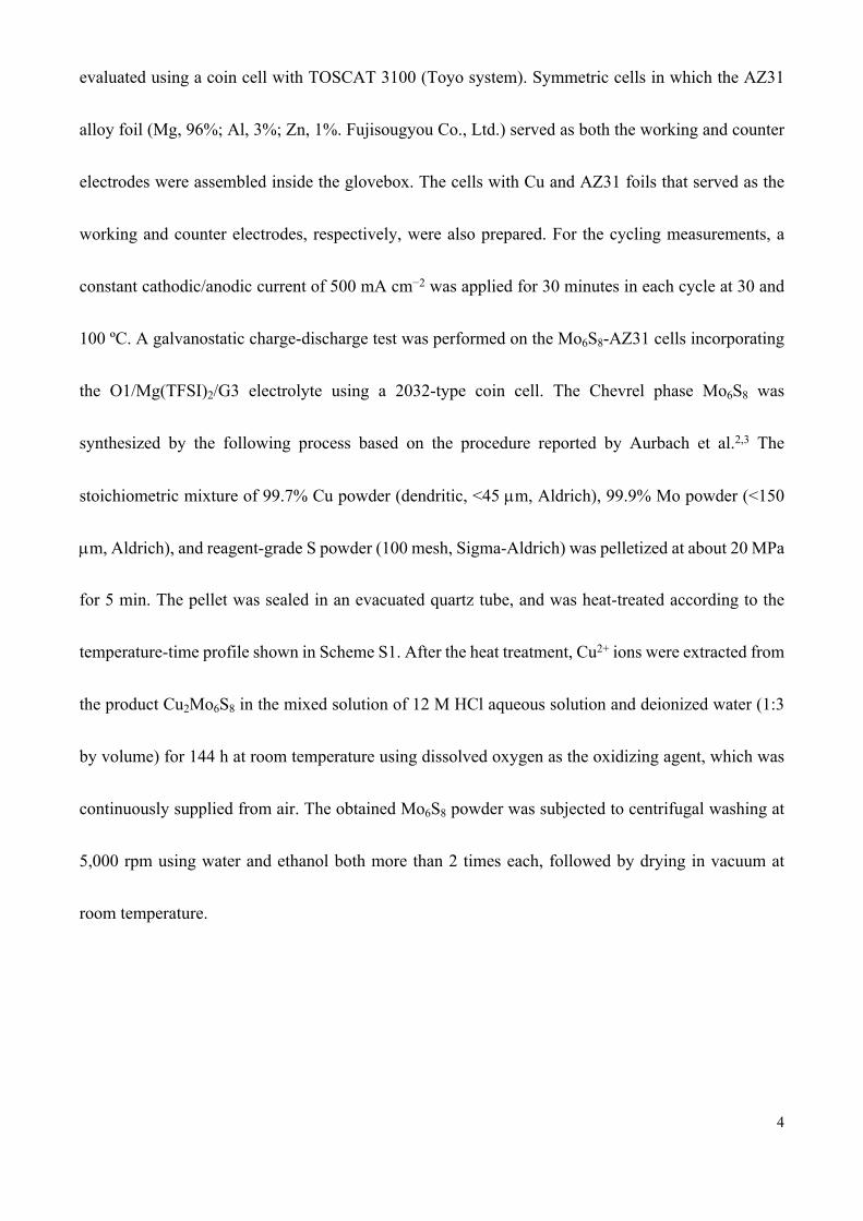
evaluated using a coin cell with TOSCAT 3100 (Toyo system). Symmetric cells in which the AZ31
alloy foil (Mg, 96%; Al, 3%; Zn, 1%. Fujisougyou Co., Ltd.) served as both the working and counter
electrodes were assembled inside the glovebox. The cells with Cu and AZ31 foils that served as the
working and counter electrodes, respectively, were also prepared. For the cycling measurements, a
constant cathodic/anodic current of 500 mA cm−2 was applied for 30 minutes in each cycle at 30 and
100 ºC. A galvanostatic charge-discharge test was performed on the Mo6S8-AZ31 cells incorporating
the O1/Mg(TFSI)2/G3 electrolyte using a 2032-type coin cell. The Chevrel phase Mo6S8 was
synthesized by the following process based on the procedure reported by Aurbach et al.2,3 The
stoichiometric mixture of 99.7% Cu powder (dendritic, <45 m, Aldrich), 99.9% Mo powder (<150
m, Aldrich), and reagent-grade S powder (100 mesh, Sigma-Aldrich) was pelletized at about 20 MPa
for 5 min. The pellet was sealed in an evacuated quartz tube, and was heat-treated according to the
temperature-time profile shown in Scheme S1. After the heat treatment, Cu2+ ions were extracted from
the product Cu2Mo6S8 in the mixed solution of 12 M HCl aqueous solution and deionized water (1:3
by volume) for 144 h at room temperature using dissolved oxygen as the oxidizing agent, which was
continuously supplied from air. The obtained Mo6S8 powder was subjected to centrifugal washing at
5,000 rpm using water and ethanol both more than 2 times each, followed by drying in vacuum at
room temperature.
5
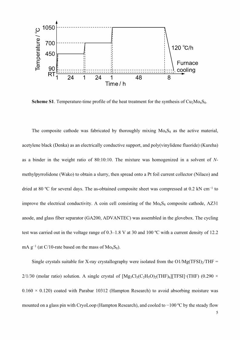
Scheme S1. Temperature-time profile of the heat treatment for the synthesis of Cu2Mo6S8.
The composite cathode was fabricated by thoroughly mixing Mo6S8 as the active material,
acetylene black (Denka) as an electrically conductive support, and poly(vinylidene fluoride) (Kureha)
as a binder in the weight ratio of 80:10:10. The mixture was homogenized in a solvent of N-
methylpyrrolidone (Wako) to obtain a slurry, then spread onto a Pt foil current collector (Nilaco) and
dried at 80 ºC for several days. The as-obtained composite sheet was compressed at 0.2 kN cm−1 to
improve the electrical conductivity. A coin cell consisting of the Mo6S8 composite cathode, AZ31
anode, and glass fiber separator (GA200, ADVANTEC) was assembled in the glovebox. The cycling
test was carried out in the voltage range of 0.3–1.8 V at 30 and 100 ºC with a current density of 12.2
mA g−1 (at C/10-rate based on the mass of Mo6S8).
Single crystals suitable for X-ray crystallography were isolated from the O1/Mg(TFSI)2/THF =
2/1/30 (molar ratio) solution. A single crystal of [Mg3Cl3(C2H5O)2(THF)6][TFSI]·(THF) (0.290 ×
0.160 × 0.120) coated with Parabar 10312 (Hampton Research) to avoid absorbing moisture was
mounted on a glass pin with CryoLoop (Hampton Research), and cooled to −100 ºC by the steady flow
6
of a nitrogen gas stream. All the diffraction measurements were performed by a Rigaku XtaLAB P200
diffractometer using multilayer mirror monochromated Mo-Ka radiation (λ = 0.71073 Å). An
empirical absorption correction was applied by the multiscan averaging of symmetry equivalent data
in the SADABS program.4 The structures were solved by the direct method using SIR92,5 and refined
full-matrix least-squares in the anisotropic approximation for non-hydrogen atoms using
SHELXL2014/7.6 The relatively large residual density, ca. ±1.0 e Å−3, is located close to the THF
molecule co-crystallized with ionic entities. All the hydrogen atoms were placed in geometrically ideal
positions and refined using the riding model. All calculations, except for the refinement, were
performed using the CrystalStructure crystallographic software package.7 Crystal data for
[Mg3Cl3(C2H5O)2(THF)6][TFSI]·(THF): C34H66Cl3F6Mg3NO13S2, Mw = 1054.28, monoclinic crystal
system, space group C2/c (no. 15), a = 27.799(3), b = 19.3811(19), c = 19.2402(2) Å, β = 103.381(2)
º, V = 10084.6(18) Å3, Z = 8, Dcalc = 1.389 g cm−3, μ = 3.785 mm−1, T = 173 K, 47863 total reflections,
11570 unique reflections, Rint = 0.0343, R1 (I > 2σ(I)) = 0.0793, R1 (all data) = 0.1012, wR2 (all data)
= 0.2786, GooF = 1.088, residual minimum and maximum electron densities −1.03 and 1.78 e Å−3,
respectively. CCDC deposited number: 1510823.
The Raman spectra were collected using a 532 nm laser Raman spectrophotometer (NRS1000,
JASCO) at ambient temperature. The samples were enclosed in a glass capillary inside the glovebox
and transferred to the instrument without exposure to air. A spectral resolution of 4 cm−1 and 30 scans
with each accumulation time of 30 seconds were employed for all the measurements.
7
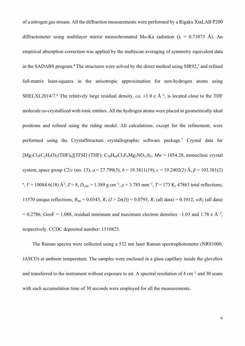
Figure S1. Solubility mapping of one selected ternary electrolyte of O1/Mg(TFSI)2/G3 as a function
of the mole fraction xO1 and molar ratio Mgtotal/G3. Circle, totally soluble at 25 ºC; triangle, soluble at
100 ºC while precipitates found at 25 ºC; cross, insoluble even at 100 ºC.
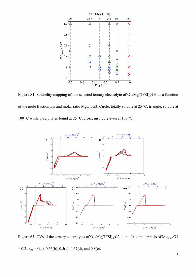
Figure S2. CVs of the ternary electrolytes of O1/Mg(TFSI)2/G3 at the fixed molar ratio of Mgtotal/G3
= 0.2. xO1 = 0(a), 0.33(b), 0.5(c), 0.67(d), and 0.8(e).
8
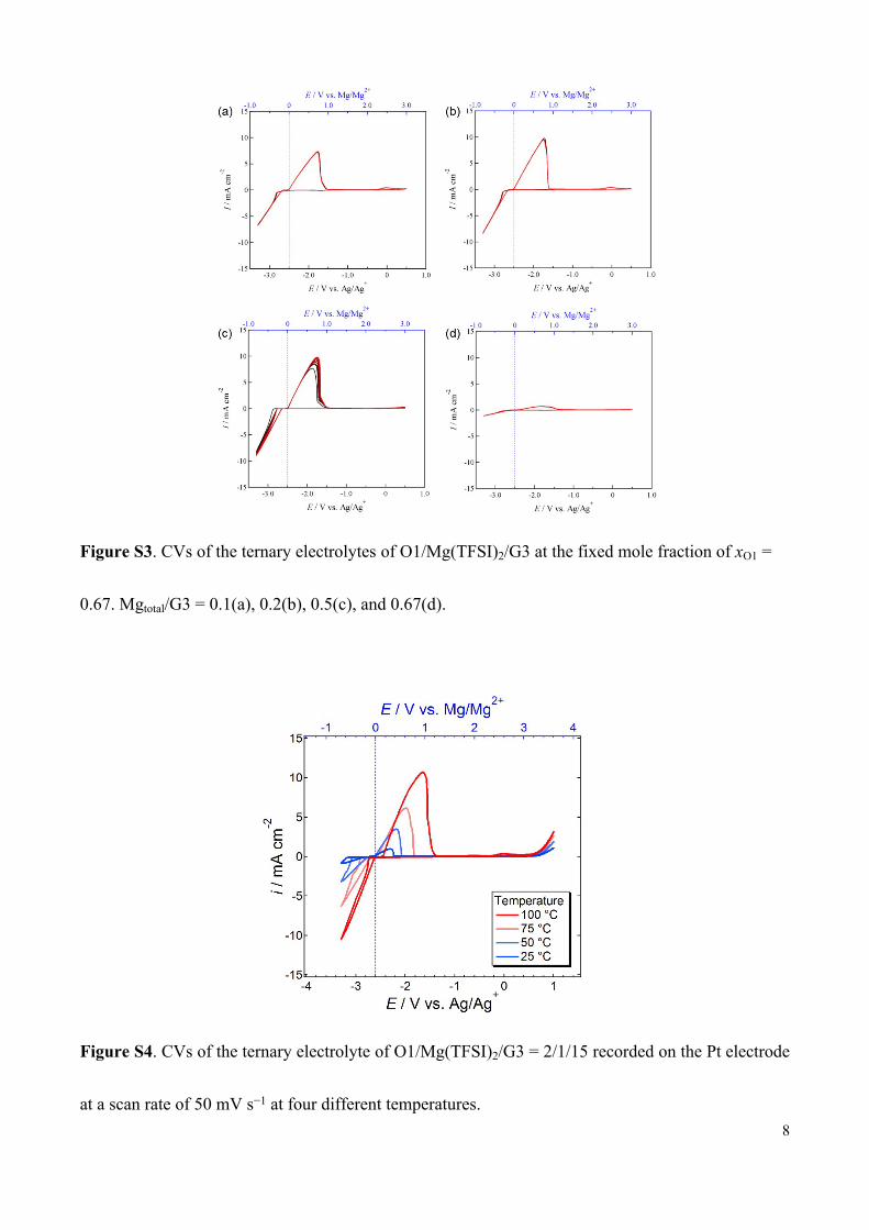
Figure S3. CVs of the ternary electrolytes of O1/Mg(TFSI)2/G3 at the fixed mole fraction of xO1 =
0.67. Mgtotal/G3 = 0.1(a), 0.2(b), 0.5(c), and 0.67(d).
Figure S4. CVs of the ternary electrolyte of O1/Mg(TFSI)2/G3 = 2/1/15 recorded on the Pt electrode
at a scan rate of 50 mV s−1 at four different temperatures.
9
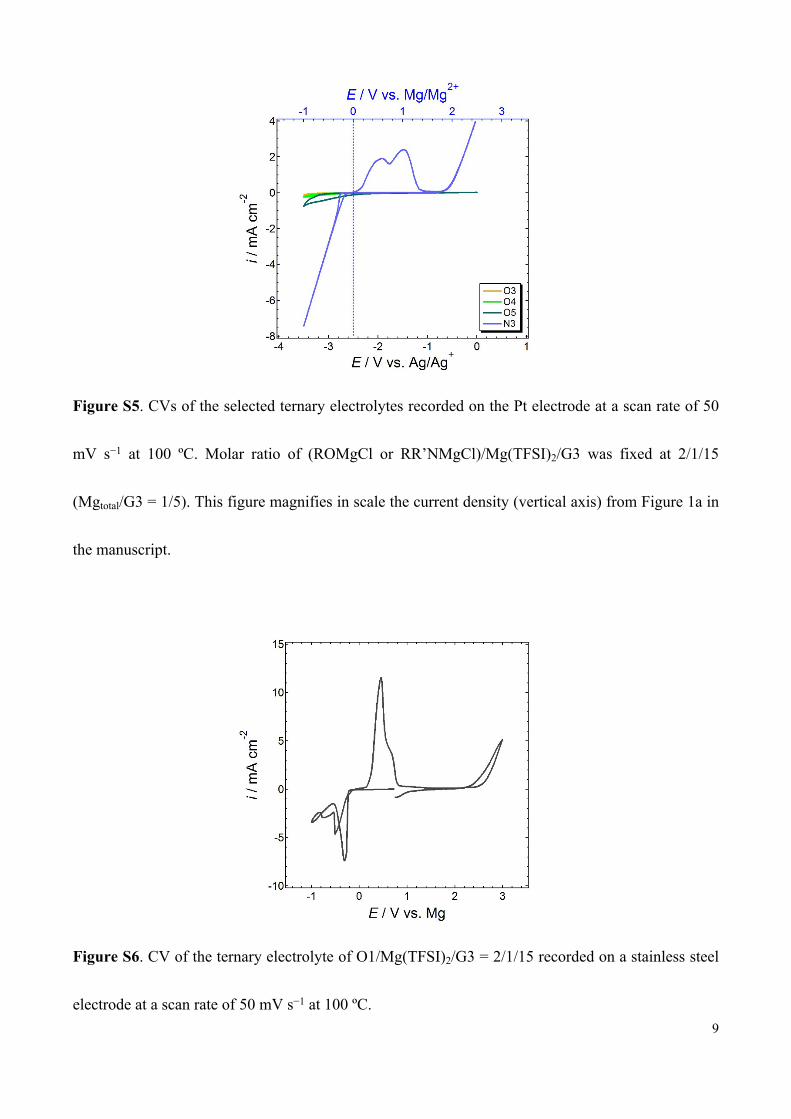
Figure S5. CVs of the selected ternary electrolytes recorded on the Pt electrode at a scan rate of 50
mV s−1 at 100 ºC. Molar ratio of (ROMgCl or RR’NMgCl)/Mg(TFSI)2/G3 was fixed at 2/1/15
(Mgtotal/G3 = 1/5). This figure magnifies in scale the current density (vertical axis) from Figure 1a in
the manuscript.
Figure S6. CV of the ternary electrolyte of O1/Mg(TFSI)2/G3 = 2/1/15 recorded on a stainless steel
electrode at a scan rate of 50 mV s−1 at 100 ºC.
10
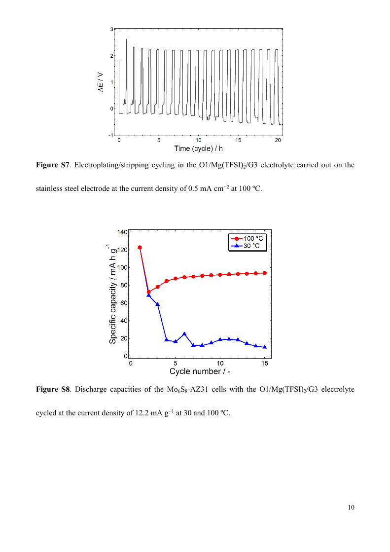
Figure S7. Electroplating/stripping cycling in the O1/Mg(TFSI)2/G3 electrolyte carried out on the
stainless steel electrode at the current density of 0.5 mA cm−2 at 100 ºC.
Figure S8. Discharge capacities of the Mo6S8-AZ31 cells with the O1/Mg(TFSI)2/G3 electrolyte
cycled at the current density of 12.2 mA g−1 at 30 and 100 ºC.
11
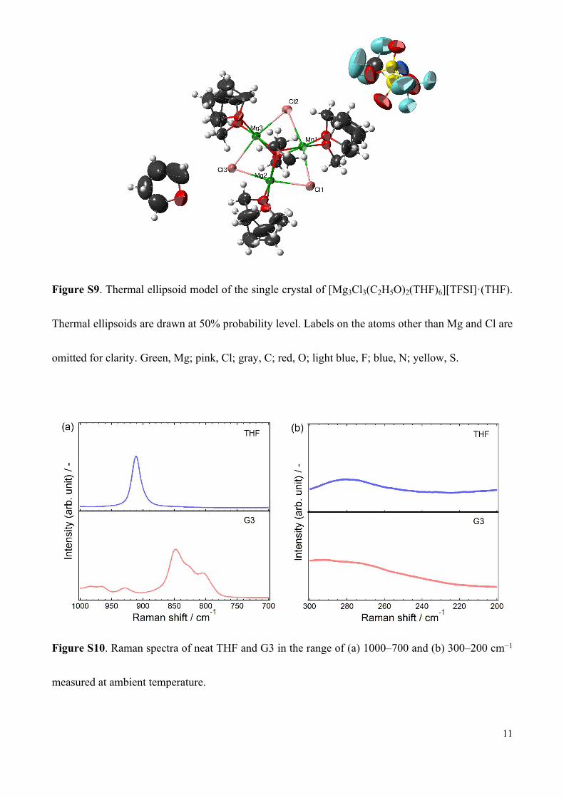
Figure S9. Thermal ellipsoid model of the single crystal of [Mg3Cl3(C2H5O)2(THF)6][TFSI]·(THF).
Thermal ellipsoids are drawn at 50% probability level. Labels on the atoms other than Mg and Cl are
omitted for clarity. Green, Mg; pink, Cl; gray, C; red, O; light blue, F; blue, N; yellow, S.
Figure S10. Raman spectra of neat THF and G3 in the range of (a) 1000–700 and (b) 300–200 cm−1
measured at ambient temperature.
12
References
1. O. Mizrahi, N. Amir, E. Pollak, O. Chusid, V. Marks, H. Gottlieb, L. Larush, E. Zinigrad, D.
Aurbach, Electrolyte Solutions with a Wide Electrochemical Window for Rechargeable
Magnesium Batteries. J. Electrochem. Soc., 2008, 15, A103–A109.
2. M. D. Levi, E. Lancry, H. Gizbar, Z. Lu, E. Levi, Y. Gofer, D. Aurbach, Kinetic and
Thermodynamic Studies of Mg2+ and Li+ Ion Insertion into the Mo6S8 Chevrel Phase. J.
Electrochem. Soc., 2004, 151, A1044–A1051.
3. E. Lancry, E. Levi, Y. Gofer, M. D. Levi, D. Aurbach, The Effect of Milling on the Performance
of a Mo6S8 Chevrel phase as a Cathode Material for Rechargeable Mg Batteries. J. Solid State
Electrochem., 2005, 9, 259–266.
4. Bruker, SADABS. 2007, Bruker AXS Inc., Madison, Wisconsin, USA.
5. A. Altomare, G. Cascarano, C. Giacovazzo, A. Guagliardi, Completion and refinement of crystal
structures with SIR92. J. Appl. Cryst., 1993, 26, 343–350.
6. G. M. Sheldrick, Crystal structure refinement with SHELXL (SHELXL version 2014/7). Acta
Cryst., 2008, A64, 112–122.
7. Rigaku, CrystalStructure 4.2: Crystal Structure Analysis Package, Rigaku Corporation (2000-
2015). Tokyo 196-8666, Japan.
Recommended