CT16 IGBD 3.0 D1
Basic
D
1.0 RIDUTTORI A VITE SENZA FINE IMPORT W1.0 WORM GEARBOXES IMPORT W1.0 SCHNECKENGETRIEBE IMPORT W W
Dopo 5 anni dalla prima presentazione, apartire da questo mese, è disponibile lanuova gamma di riduttori a vite senzafine serie W.La nuova gamma comprende le taglie25, 30, 130 e 150.Sono intercambiabili alla serieprecedente, senza giunto in entrata, inalluminio le taglie 25-90 mentre le taglie110-150 in ghisa e tutte verniciate di blu.
1.1 Technical characteristics 1.1 Technische Eigenschaften1.1 Caratteristiche tecniche
After 5 years from the first presentation,it’s now available the new W wormgearboxes range.We introduce also the new sizes 25, 30,130 and 150.The performances and the dimensionsare the same to the old series but without
input coupling and all sizes painted.
5 Jahre nach der ersten Auflage können wirIhnen eine neue Auswahl anSchneckengetrieben der W-Serie anbieten,die jetzt auch in den Größen 25, 30, 130und 150 verfügbar sind.Sie sind austauschbar mit denVorgängermodellen, ohne Kupplung,verfügbar in den Größen 25 - 90 ausAluminum und in den Größen 110 -150 ausGusseisen und alle blau lackiert.
W
1.1 Caratteristiche tecniche Technical characteristics Technische Eigenschaften D1
1.2 Designazione Designation Bezeichnungen D2
1.2 Versioni Versions Ausführungen D3
1.4 Lubrificazione Lubrication Schmierung D6
1.5 Carichi radiali e assiali Axial and overhung loads Radiale und Axiale Belastungen D7
1.6 Prestazioni riduttori Gearboxes performances Leistungen der Getriebe D10
1.8 Dimensioni Dimensions Abmessungen D13
1.9 Accessori Accessories Zubehör D17
CT16 IGBD 3.0D2
Basic
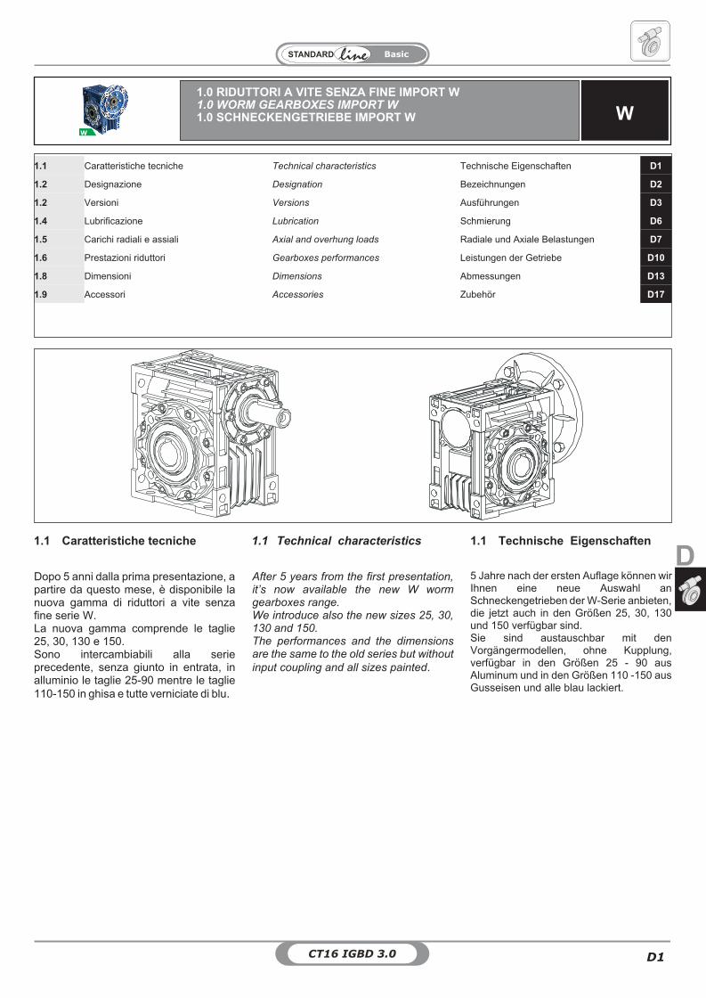
1.2 Bezeichnung1.2 Designation1.2 Designazione 1.2 Bezeichnung
CODE: Example of order: "WMI 40 FA 1/7.5 71B5"
WMI
25304050637590
110130150
�
FAFBFC
— —
Veditabelle
prestazioni
Seeperformanc
e tables
SieheLeistungs-tabellen
— —
80B5...
80B14�
— —
—
DX
SIN
M1M2M3M4M5M6
12345678
— LookCT 18
I —
WEB: Reference Designation
MaschineTyp
ConnectionSize
OutputVersion
MountingVersion
OutputFlange
Reductionratio
IEC typeand
Input Shaft
InputVersion
InputShaft
DesignazioneMotori
Designation
Motors
BezeichnungMotoren
Type
Shaft
Diameter
Shaft
Diameter
Mounting
Position
Output
Flange
Mountingpositions
PositionTerminal
Box
00M
01Tycon
02SIZE
03OV
03aMV
03bOF
04IR
05IECT
06IV
07IS
14TYPSD
15SD
16MPOF
17MP
19PMT
WI WMI
01 TYPCON - Tipo connessione TYPCON - Type Connection TYPCON - Typ Verbindung
M - Macchina M - Maschine M - Getriebe00
W
SIZE - Grandezza SIZE - Size SIZE - Größe02
Flange mounted
FA FB
Universal foot
-
FC
5
6
8
7
1-5 standard
1
2 4
3
5
6
8
7
1-5 standard
1
2 4
3
0303a03b
OV - Versione Uscita OV - Output Version OV - AbtriebausführungMV - Versione Montaggio MV - Mounting Version MV - BauversionOF - Flangia Uscita OF - Output Flange OF - Flansche am Abtrieb
Posizioni della MorsettieraPosition Terminal BoxMontagpositionKlemmenkasten
ElencoversioniVersionsAusführungen
Il senso dell'elica èdestroThe helix is right-hande
Die Schnecke ist rechtsgängigFA FB
-
FC
WIWMI
W
WI - WMI 25 30 40 50 63 75 90 110 130 150
WInot available �
1
2 4
3
5
6
8
7
CT16 IGBD 3.0 D3
Basic
D
1.2 Designation1.2 Designazione 1.2 Bezeichnung
050607
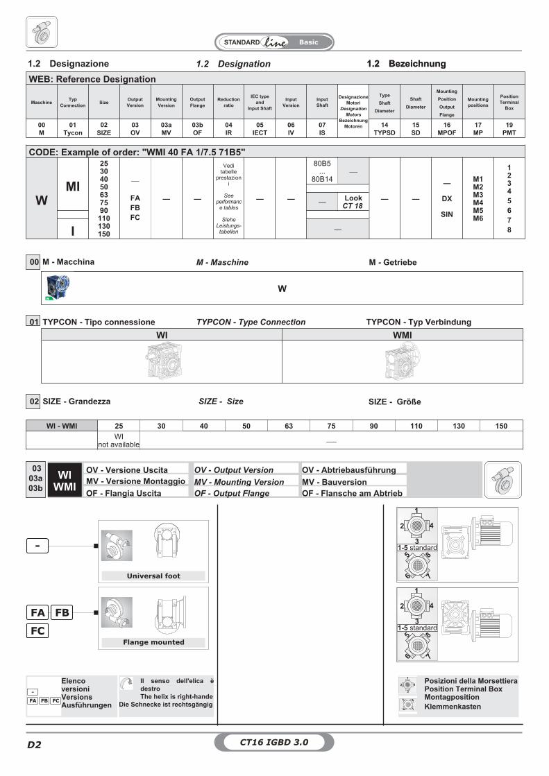
IECT - Tipo IEC e Albero Entrata IECT - IEC type and Input Shaft OV - IEC Typ und AntriebswelleIV - Versione Entrata IV - Input Version IV - AntriebausführungIS - Albero Entrata IS - Input shaft IS - Antriebswelle
WMI
IEC N M P
ir
7.5 10 15 20 25 30 40 50 60 80 100
DWMI 25 56 B14 50 65 80 ø 9 ø 9 ø 9 ø 9 - ø 9 ø 9 ø 9 ø 9 - -
WMI 30
63 B5 95 115 140ø 11 ø 11 ø 11 ø 11 ø 11 ø 11 ø 11 ø 11 - - -
63 B14 60 75 9056 B5 80 100 120
ø 9 ø 9 ø 9 ø 9 ø 9 ø 9 ø 9 ø 9 ø 9 ø 9 -56 B14 50 65 80
WMI 40
71 B5 110 130 160ø 14 ø 14 ø 14 ø 14 ø 14 ø 14 ø 14 - - - -
71 B14 70 85 10563 B5 95 115 140
ø 11 ø 11 ø 11 ø 11 ø 11 ø 11 ø 11 ø 11 ø 11 ø 11 ø 1163 B14 60 75 9056 B5 80 100 120 - - - - - - - ø 9 ø 9 ø 9 ø 9
WMI 50
80 B5 130 165 200ø 19 ø 19 ø 19 ø 19 ø 19 ø 19 - - - - -
80 B14 80 100 12071 B5 110 130 160
ø 14 ø 14 ø 14 ø 14 ø 14 ø 14 ø 14 ø 14 ø 14 ø 14 -71 B14 70 85 10563 B5 95 115 140 - - - - - - ø 11 ø 11 ø 11 ø 11 ø 11
WMI 63
90 B5 130 165 200ø 24 ø 24 ø 24 ø 24 ø 24 ø 24 - - - - -
90 B14 95 115 14080 B5 130 165 200
ø 19 ø 19 ø 19 ø 19 ø 19 ø 19 ø 19 ø 19 ø 19 - -80 B14 80 100 12071 B5 110 130 160
- - - - - - ø 14 ø 14 ø 14 ø 14 ø 1471 B14 70 85 105
WMI 75
100/112 B5 180 215 250ø 28 ø 28 ø 28 - - - - - - - -
100/112 B14 110 130 16090 B5 130 165 200
ø 24 ø 24 ø 24 ø 24 ø 24 ø 24 ø 24 - - - -90 B14 95 115 14080 B5 130 165 200
- - - ø 19 ø 19 ø 19 ø 19 ø 19 ø 19 ø 19 ø 1980 B14 80 100 12071 B5 110 130 160 - - - - - - - ø 14 ø 14 ø 14 ø 14
WMI 90
100/112 B5 180 215 250ø 28 ø 28 ø 28 ø 28 ø 28 ø 28 - - - - -
100/112 B14 110 130 16090 B5 130 165 200
ø 24 ø 24 ø 24 ø 24 ø 24 ø 24 ø 24 ø 24 ø 24 - -90 B14 95 115 14080 B5 130 165 200
- - - - - - ø 19 ø 19 ø 19 ø 19 ø 1980 B14 80 100 120
WMI 110
132 B5 230 265 300 ø 38 ø 38 ø 38 ø 38 - - - - - - -100/112 B5 180 215 250 ø 28 ø 28 ø 28 ø 28 ø 28 ø 28 ø 28 ø 28 ø 28 - -
90 B5 130 165 200 - - - - ø 24 ø 24 ø 24 ø 24 ø 24 ø 24 ø 2480 B5 130 165 200 - - - - - - - - - ø 19 ø 19
WMI 130132 B5 230 265 300 ø 38 ø 38 ø 38 ø 38 ø 38 ø 38 ø 38 - - - -
100/112 B5 180 215 250 - - - - ø 28 ø 28 ø 28 ø 28 ø 28 ø 28 ø 2890 B5 130 165 200 - - - - - - - - - ø 24 ø 24
WMI 150160 B5 250 300 350 ø 42 ø 42 ø 42 ø 42 - - - - - - -132 B5 230 265 300 - - - ø 38 ø 38 ø 38 ø 38 ø 38 - - -
100/112 B5 180 215 250 - - - - - - - ø 28 ø 28 ø 28 ø 28
.
DNMP
(Vedi prestazioni). Tutti i valori dei rapportisono approssimati. Per applicazioni dovenecessita il valore esatto consultare il ns.servizio tecnico.
IR- Rapporto di riduzione IR - Reduction ratio IR - Übersetzungsverhältnis04
(See ratings). Ratios are approximatevalues. If you need exact values for aspecific application, please contact ourEngineering.
(Siehe "Leistungen"). Bei allen Werten derÜbersetzungen handelt es sich umapproximative Wertangaben. BeiApplikationen, bei denen die exakteWertangabe erforderlich ist, muss unserTechnischer Kundendienst konsultiertwerden.
CT16 IGBD 3.0D4
Basic
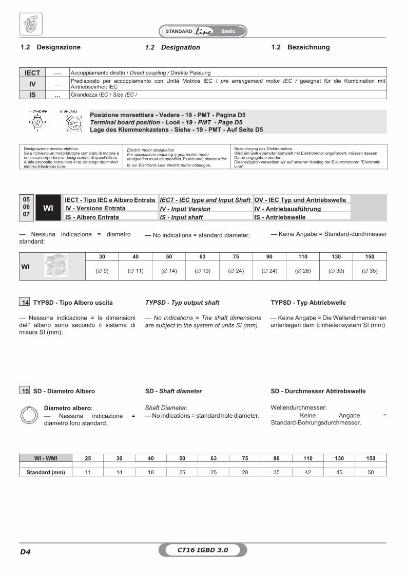
Posizione morsettiera - Vedere - 19 - PMT - Pagina D5Terminal board position - Look - 19 - PMT - Page D5
Lage des Klemmenkastens - Siehe - 19 - PMT - Auf Seite D5
Designazione motore elettricoSe è richiesto un motoriduttore completo di motore ènecessario riportare la designazione di quest'ultimo.A tale proposito consultare il ns. catalogo dei motorielettrici Electronic Line.
Electric motor designationFor applications requiring a gearmotor, motordesignation must be specified.To this end, please refer
to our Electronic Line electric motor catalogue.
Bezeichnung des ElektromotorsWird ein Getriebemotor komplett mit Elektromotor angefordert, müssen dessenDaten angegeben werden.Diesbezüglich verweisen wir auf unseren Katalog der Elektromotoren "ElectronicLine".
IECT�
Accoppiamento diretto / Direct coupling / Direkte Passung
IV�
Predisposto per accoppiamento con Unità Motrice IEC / pre arrangement motor IEC / geeignet für die Kombination mitAntriebseinheit IEC
IS ... Grandezza IEC / Size IEC /
— Nessuna indicazione = diametrostandard;
— Keine Angabe = Standard-durchmesser— No indications = standard diameter;
050607
WI
30 40 50 63 75 90 110 130 150
(� 9) (� 11) (� 14) (� 19) (� 24) (� 24) (� 28) (� 30) (� 35)
IECT - Tipo IEC e Albero Entrata IECT - IEC type and Input Shaft OV - IEC Typ und AntriebswelleIV - Versione Entrata IV - Input Version IV - AntriebausführungIS - Albero Entrata IS - Input shaft IS - Antriebswelle
WI
WI - WMI 25 30 40 50 63 75 90 110 130 150
Standard (mm) 11 14 18 25 25 28 35 42 45 50
15 SD - Diametro Albero SD - Shaft diameter SD - Durchmesser Abtirebswelle
Diametro albero:� Nessuna indicazione =diametro foro standard.
Wellendurchmesser:� Keine Angabe =Standard-Bohrungsdurchmesser.
Shaft Diameter:
� No indications = standard hole diameter.
1.2 Designation1.2 Designazione 1.2 Bezeichnung
14 TYPSD - Tipo Albero uscita TYPSD - Typ output shaft TYPSD - Typ Abtriebwelle
� No indications = The shaft dimensions
are subject to the system of units SI (mm).
� Keine Angabe = Die Wellendimensionenunterliegen dem Einheitensystem SI (mm)
� Nessuna indicazione = le dimensionidell' albero sono secondo il sistema dimisura SI (mm);
CT16 IGBD 3.0 D5
Basic
D
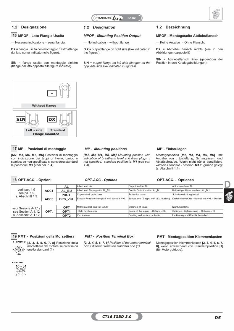
� No indication = without flange;D X = output flange on right side (like indicated inthe figures);
SIN = output flange on left side (flanges on theopposite side like indicated in figures).
� Nessuna indicazione = sena flangia;
DX = flangia uscita con montaggio destro (flangedal lato come indicato nelle figure);
SIN = flange uscita con montaggio sinistro(flange dal lato opposto alle figure indicate).
� Keine Angabe = Ohne Flansch;
DX = Abtriebs- flansch rechts (wie in denAbbildungen dargestellt)
SIN = Abtriebsflansch links (gegenüber derPosition in den Katalogabbildungen).
1.2 Designation1.2 Designazione 1.2 Bezeichnung
16 MPOF - Lato Flangia Uscita MPOF - Mounting Position Output MPOF - Montageseite Abtiebsflansch
Flange mounted
StandardLeft - side
SIN DX
Without flange
-
18 OPT-ACC. - Opzioni OPT-ACC - Options OPT-ACC. - Optionen
MP - Posizioni di montaggio MP - Mounting positions MP - Einbaulagen17
[M2, M3, M4, M5, M6] Posizioni di montaggiocon indicazione dei tappi di livello, carico escarico; se non specificato si considera standardla posizione M1 (vedi par. 1.4)
Montageposition [M2, M3, M4, M5, M6] mitAngabe von . Entlüftung, Schaugläsern undAblaßschraube. Wenn nicht näher spezifiziert,wird die Standard - position M1 zugrunde gelegt(s. Abschnitt 1.4).
[M2, M3, M4, M5, M6] Mounting position withindication of breatherm level and drain plugs; ifnot specified, standard position is M1 (see par.1.4).
PMT - Posizioni della Morsettiera PMT - Position Terminal Box PMT - Montagposition Klemmenkasten19
[2, 3, 4, 5, 6, 7, 8] Posizione dellamorsettiera del motore se diversa daquella standard (1).
Montageposition Klemmenkasten [2, 3, 4, 5, 6, 7,8], wenn abweichend von Standardposition [1](für Motorgetriebe).
[2, 3, 4, 5, 6, 7, 8] Position of the motor terminalbox if different from the standard one (1).
vedi par. 1.9see pa. 1.9
s. Abschnitt 1.9
ACC1AL Alberi lenti - AL Output shafts - AL Abtriebswellen - AL
AL_BU Alberi lenti Bisporgenti - AL_BU Double Output shafts - AL_BU Beidseitige Abtriebswellen - AL_BU
PROT. Coperchio di protezione Protection cover Schultzvorrichtungdeckel
ACC3 BRS_VKL Braccio Reazione Semplice_con boccola_VKL Torque arm - Single_with VKL_bushing Drehmomentstütze - Normal_mit VKL - Buchse
vedi Sezione A-1.12see Section A-1.12s. Abschnitt A-1.12
OPT.OPT Materiale degli anelli di tenuta Materials of Seals Dichtungsstoffe
OPT1 Stato fornitura olio Scope of the supply - Options - OIL Optionen - Lieferzustand - Optionen - Öl
OPT2 Verniciatura Painting and surface protection Lackierung und Oberflächenschutzl
CT16 IGBD 3.0D6
Basic
1.4 Lubrication1.4 Lubrificazione 1.4 Schmierung
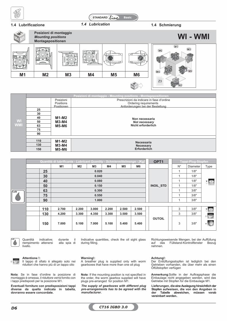
Posizioni di montaggioMounting positions
MontagepositionenWI - WMI
M1 M2 M3 M4 M5 M6
WIWMI
Posizioni di montaggio - Mounting positions - MontagepositionenPosizioniPositions
Positionen
Prescrizioni da indicare in fase d'ordineOrdering requirements
Anforderungen bei der Bestellung25
M1-M2M3-M4M5-M6
Non necessariaNot necessary
Nicht erforderlich
304050637590
110 M1-M2M3-M4M5-M6
NecessariaNecessary
Erforderlich130
150
M1M4 M5
Z3
WIWMI
Quantità di lubrificante - Lubricant Quantity - Schmiermittelmenge - [Kg] OPT1 Tappi-Plug-Stopfen
M1 M2 M3 M4 M5 M6 N° Diameter Type
25 0.020
INOIL_STD
1 1/8"
30 0.040 1 1/8"
40 0.080 1 1/8"
50 0.150 1 1/8"
63 0.300 1 3/8"
75 0.550 1 3/8"
90 1.000 1 3/8"
110 2.700 2.200 3.000 2.200 2.500 2.500
OUTOIL
3 3/8"
130 4.200 3.300 4.350 3.300 3.500 3.500 3 3/8"
150 7.000 5.100 7.000 5.100 5.400 5.400 3 3/8"
Lub
Attentione !:ll tappo di sfiato è allegato solo neiriduttori che hanno più di un tappo olio
Nota: Se in fase d’ordine la posizione dimontaggio è omessa, il riduttore verrà fornito coni tappi predisposti per la posizione M1.
Warning!:A breather plug is supplied only with wormgearboxes that have more than one oil plug
Note: If the mounting position is not specified inthe order, the worm gearbox supplied will haveplugs pre-arranged for position M1.
Achtung!:Der Entlüftungsstopfen ist lediglich bei denGetrieben vorhanden, die über mehr als einenÖlfüllstopfen verfügen
Anmerkung:Sollte in der Auftragsphase dieEinbaulage nicht angegeben werden, wird dasGetriebe mit Stopfen für die Einbaulage M1.
Eventuali forniture con predisposizioni tappidiverse da quella indicata in tabella,dovranno essere concordate.
The supply of gearboxes with different plugpre-arrangements has to be agreed with themanufacturer.
Lieferungen, die eine Auslegung hinsichtlich derStopfen aufweisen, die von den Angaben inder Tabelle abweichen, müssen vorabvereinbart werden..
Quantità indicative; durante ilriempimento attenersi alla spia dilivello.
Indicative quantities, check the oil sight glassduring filling.
Richtungsweisende Mengen, bei der Auffüllungauf das Füllstand-Kontrollfenster Bezugnehmen.
Lub
CT16 IGBD 3.0 D7
Basic
D
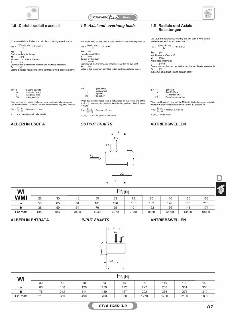
1.5 Axial and overhung loads1.5 Carichi radiali e assiali 1.5 Radiale und AxialeBelastungen
Il carico radiale sull’albero si calcola con la seguente formula:
Fre (N)Carico radiale risultanteM (Nm)Momento torcente sull’alberoD (mm)Diametro dell’elemento di trasmissione montato sull’alberoFr (N)Valore di carico radiale massimo ammesso (ved. tabelle relative)
fz = 1,1 pignone dentato1,4 ruota per catena1,7 puleggia a gola2,5 puleggia piana
Quando il carico radiale risultante non è applicato sulla mezzeriadell’albero occorre calcolare quello effettivo con la seguente formula:
a , b , x = valori riportati nelle tabelle
The radial load on the shaft is calculated with the following formula:
Fre (N)Resulting radial loadM (Nm)Torque on the shaftD (mm)Diameter of the transmission member mounted on the shaftFr (N)Value of the maximum admitted radial load (see relative tables)
fz = 1,1 gear pinion1,4 chain wheel1,7 v-pulley2,5 flat pulley
When the resulting radial load is not applied on the centre line of theshaft it is necessary to calculate the effective load with the followingformula:
a , b , x = values given in the tables
Die Querbelastung (Querkraft) auf der Welle wird durchnachstehende Formel berechnet:
Fre (N)resultierende QuerkraftM (Nm)WellendrehmomentD (mm)Durchmesser des an der Welle montierten AntriebselementsFr (N)max. zul. Querkraft (siehe entspr. Tafel)
fz = 1,1 Zahnrad1,4 Rad für Kette1,7 Flanschscheibe2,5 Flachriemenscheibe
Wenn die Querkraft nicht auf die Mitte der Welle bezogen ist, ist dieeffektive Kraft durch nachstehende Formel zu berechnen:
a , b , x: siehe Tafeln
OUTPUT SHAFTSALBERI IN USCITA ABTRIEBSWELLEN
X
Frx
Fr
L/2
L
Fa
WIWMI
Fr2 (N)
25 30 40 50 63 75 90 110 130 150
a 50 65 84 101 120 131 162 176 188 215
b 38 50 64 76 95 101 122 136 148 174
Fr2 max 1350 1830 3490 4840 6270 7380 8180 12000 13500 18000
INPUT SHAFTSALBERI IN ENTRATA ANTRIEBSWELLEN
X
Frx
Fr
L/2
WI Fr1 (N)
30 40 50 63 75 90 110 130 150
a 86 106 129 159 192 227 266 314 350
b 76 94.5 114 139 167 202 236 274 310
Fr1 max 210 350 490 700 980 1270 1700 2100 2800
CT16 IGBD 3.0D8
Basic
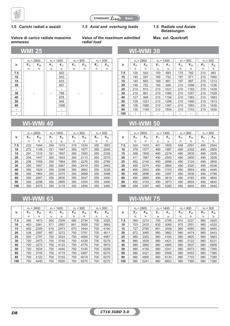
1.5 Axial and overhung loads1.5 Carichi radiali e assiali 1.5 Radiale und AxialeBelastungen
WMI 25
irn1 = 2800 n1 = 1400 n1 = 900 n1 = 500Fr1 Fr2 Fr1 Fr2 Fr1 Fr2 Fr1 Fr2
N N N N N N N N
7.5
- -
503
- -
10 55315 63320 697- -
30 79840 87850 94660 1006- -- -
WI-WMI 30
WI-WMI 40 WI-WMI 50
Value of the maximum admittedradial load
Valore di carico radiale massimoammesso
Max. zul. Querkraft
irn1 = 2800 n1 = 1400 n1 = 900 n1 = 500Fr1 Fr2 Fr1 Fr2 Fr1 Fr2 Fr1 Fr2
N N N N N N N N
7.5 125 542 150 683 175 792 210 96310 140 597 169 752 197 871 210 106015 140 683 169 861 197 997 210 121320 146 752 190 948 210 1098 210 133625 210 810 210 1021 210 1183 210 143930 210 861 210 1085 210 1257 210 152940 127 948 210 1194 210 1383 210 168350 128 1021 210 1286 210 1490 210 181360 126 1085 210 1367 210 1583 210 183080 130 1194 210 1504 210 1743 210 1830
100 - - - - - - - -
irn1 = 2800 n1 = 1400 n1 = 900 n1 = 500Fr1 Fr2 Fr1 Fr2 Fr1 Fr2 Fr1 Fr2
N N N N N N N N
7.5 233 1044 294 1315 319 1524 350 185310 272 1149 331 1447 350 1677 350 204015 291 1315 331 1657 350 1920 350 233520 204 1447 350 1824 350 2113 350 257025 236 1559 350 1964 350 2276 350 276930 350 1657 350 2087 350 2419 350 294240 350 1824 350 2298 350 2662 350 323850 350 1964 350 2475 350 2868 350 348860 350 2087 350 2630 350 3047 350 349080 350 2298 350 2895 350 3354 350 3490
100 350 2475 350 3118 350 3490 350 3490
irn1 = 2800 n1 = 1400 n1 = 900 n1 = 500Fr1 Fr2 Fr1 Fr2 Fr1 Fr2 Fr1 Fr2
N N N N N N N N
7.5 324 1433 401 1805 448 2091 490 254410 378 1577 490 1987 490 2302 490 280015 399 1805 490 2274 490 2635 490 320520 417 1987 490 2503 490 2900 490 352825 482 2140 490 2696 490 3124 490 380030 490 2274 490 2865 490 3320 490 403840 490 2503 490 3153 490 3654 490 444550 490 2696 490 3397 490 3936 490 478860 490 2865 490 3610 490 4183 490 484080 490 3153 490 3973 490 4604 490 4840
100 490 3397 490 4280 490 4840 490 4840
WI-WMI 63 WI-WMI 75
irn1 = 2800 n1 = 1400 n1 = 900 n1 = 500Fr1 Fr2 Fr1 Fr2 Fr1 Fr2 Fr1 Fr2
N N N N N N N N
7.5 395 1873 500 2359 580 2734 700 332510 463 2061 571 2597 661 3009 700 366015 492 2359 615 2973 670 3444 700 419020 538 2597 667 3272 700 3791 700 461125 593 2797 700 3524 700 4084 700 496730 700 2973 700 3745 700 4339 700 527940 700 3272 700 4122 700 4776 700 581050 700 3524 700 4440 700 5145 700 625960 700 3745 700 4719 700 5467 700 627080 700 4122 700 5193 700 6018 700 6270
100 700 4440 700 5595 700 6270 700 6270
irn1 = 2800 n1 = 1400 n1 = 900 n1 = 500Fr1 Fr2 Fr1 Fr2 Fr1 Fr2 Fr1 Fr2
N N N N N N N N
7.5 560 2210 700 2785 810 3227 980 392510 703 2433 830 3065 975 3551 980 432015 727 2785 851 3509 980 4065 980 494520 872 3065 980 3862 980 4474 980 544325 980 3302 980 4160 980 4820 980 586330 980 3509 980 4421 980 5122 980 623140 980 3862 980 4865 980 5637 980 685850 980 4160 980 5241 980 6073 980 738060 980 4421 980 5569 980 6453 980 738080 980 4865 980 6130 980 7103 980 7380
100 980 5241 980 6603 980 7380 980 7380
CT16 IGBD 3.0 D9
Basic
D
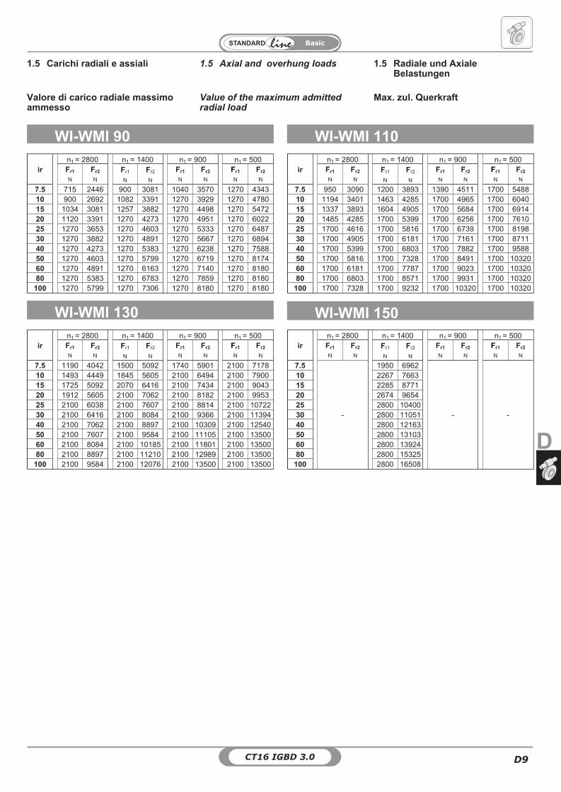
1.5 Axial and overhung loads1.5 Carichi radiali e assiali 1.5 Radiale und AxialeBelastungen
WI-WMI 90 WI-WMI 110
WI-WMI 130
Value of the maximum admittedradial load
Valore di carico radiale massimoammesso
Max. zul. Querkraft
irn1 = 2800 n1 = 1400 n1 = 900 n1 = 500Fr1 Fr2 Fr1 Fr2 Fr1 Fr2 Fr1 Fr2
N N N N N N N N
7.5 715 2446 900 3081 1040 3570 1270 434310 900 2692 1082 3391 1270 3929 1270 478015 1034 3081 1257 3882 1270 4498 1270 547220 1120 3391 1270 4273 1270 4951 1270 602225 1270 3653 1270 4603 1270 5333 1270 648730 1270 3882 1270 4891 1270 5667 1270 689440 1270 4273 1270 5383 1270 6238 1270 758850 1270 4603 1270 5799 1270 6719 1270 817460 1270 4891 1270 6163 1270 7140 1270 818080 1270 5383 1270 6783 1270 7859 1270 8180
100 1270 5799 1270 7306 1270 8180 1270 8180
irn1 = 2800 n1 = 1400 n1 = 900 n1 = 500Fr1 Fr2 Fr1 Fr2 Fr1 Fr2 Fr1 Fr2
N N N N N N N N
7.5 950 3090 1200 3893 1390 4511 1700 548810 1194 3401 1463 4285 1700 4965 1700 604015 1337 3893 1604 4905 1700 5684 1700 691420 1485 4285 1700 5399 1700 6256 1700 761025 1700 4616 1700 5816 1700 6739 1700 819830 1700 4905 1700 6181 1700 7161 1700 871140 1700 5399 1700 6803 1700 7882 1700 958850 1700 5816 1700 7328 1700 8491 1700 1032060 1700 6181 1700 7787 1700 9023 1700 1032080 1700 6803 1700 8571 1700 9931 1700 10320
100 1700 7328 1700 9232 1700 10320 1700 10320
irn1 = 2800 n1 = 1400 n1 = 900 n1 = 500Fr1 Fr2 Fr1 Fr2 Fr1 Fr2 Fr1 Fr2
N N N N N N N N
7.5 1190 4042 1500 5092 1740 5901 2100 717810 1493 4449 1845 5605 2100 6494 2100 790015 1725 5092 2070 6416 2100 7434 2100 904320 1912 5605 2100 7062 2100 8182 2100 995325 2100 6038 2100 7607 2100 8814 2100 1072230 2100 6416 2100 8084 2100 9366 2100 1139440 2100 7062 2100 8897 2100 10309 2100 1254050 2100 7607 2100 9584 2100 11105 2100 1350060 2100 8084 2100 10185 2100 11801 2100 1350080 2100 8897 2100 11210 2100 12989 2100 13500
100 2100 9584 2100 12076 2100 13500 2100 13500
WI-WMI 150
irn1 = 2800 n1 = 1400 n1 = 900 n1 = 500Fr1 Fr2 Fr1 Fr2 Fr1 Fr2 Fr1 Fr2
N N N N N N N N
7.5
-
1950 6962
- -
10 2267 766315 2285 877120 2674 965425 2800 1040030 2800 1105140 2800 1216350 2800 1310360 2800 1392480 2800 15325
100 2800 16508
CT16 IGBD 3.0D10
Basic
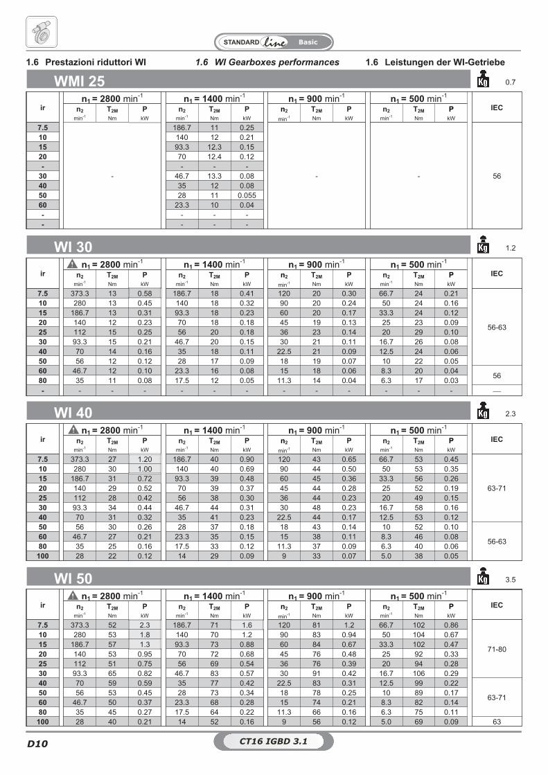
WMI 25 0.7
irn1 = 2800 min-1 n1 = 1400 min-1 n1 = 900 min-1 n1 = 500 min-1
IECn2 T2M P n2 T2M P n2 T2M P n2 T2M Pmin-1 Nm kW min-1 Nm kW min-1 Nm kW min-1 Nm kW
7.5
-
186.7 11 0.25
- - 56
10 140 12 0.2115 93.3 12.3 0.1520 70 12.4 0.12- - - -
30 46.7 13.3 0.0840 35 12 0.0850 28 11 0.05560 23.3 10 0.04- - - -- - - -
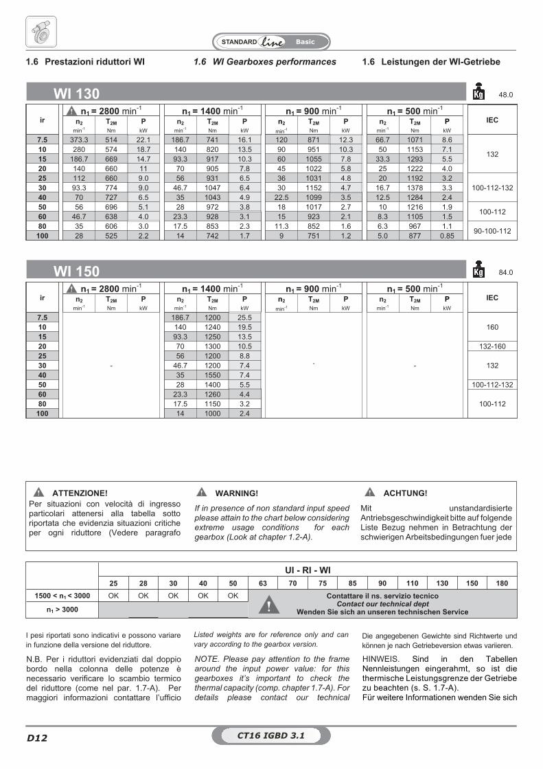
1.6 WI Gearboxes performances 1.6 Leistungen der WI-Getriebe1.6 Prestazioni riduttori WI
WI 30 1.2
irn1 = 2800 min-1 n1 = 1400 min-1 n1 = 900 min-1 n1 = 500 min-1
IECn2 T2M P n2 T2M P n2 T2M P n2 T2M Pmin-1 Nm kW min-1 Nm kW min-1 Nm kW min-1 Nm kW
7.5 373.3 13 0.58 186.7 18 0.41 120 20 0.30 66.7 24 0.21
56-63
10 280 13 0.45 140 18 0.32 90 20 0.24 50 24 0.1615 186.7 13 0.31 93.3 18 0.23 60 20 0.17 33.3 24 0.1220 140 12 0.23 70 18 0.18 45 19 0.13 25 23 0.0925 112 15 0.25 56 20 0.18 36 23 0.14 20 29 0.1030 93.3 15 0.21 46.7 20 0.15 30 21 0.11 16.7 26 0.0840 70 14 0.16 35 18 0.11 22.5 21 0.09 12.5 24 0.0650 56 12 0.12 28 17 0.09 18 19 0.07 10 22 0.0560 46.7 12 0.10 23.3 16 0.08 15 18 0.06 8.3 20 0.04
5680 35 11 0.08 17.5 12 0.05 11.3 14 0.04 6.3 17 0.03
- - - - - - - - - - - - - �
WI 40 2.3
irn1 = 2800 min-1 n1 = 1400 min-1 n1 = 900 min-1 n1 = 500 min-1
IECn2 T2M P n2 T2M P n2 T2M P n2 T2M Pmin-1 Nm kW min-1 Nm kW min-1 Nm kW min-1 Nm kW
7.5 373.3 27 1.20 186.7 40 0.90 120 43 0.65 66.7 53 0.45
63-71
10 280 30 1.00 140 40 0.69 90 44 0.50 50 53 0.3515 186.7 31 0.72 93.3 39 0.48 60 45 0.36 33.3 56 0.2620 140 29 0.52 70 39 0.37 45 44 0.28 25 52 0.1925 112 28 0.42 56 38 0.30 36 44 0.23 20 49 0.1530 93.3 34 0.44 46.7 44 0.31 30 48 0.23 16.7 58 0.1640 70 31 0.32 35 41 0.23 22.5 44 0.17 12.5 53 0.1250 56 30 0.26 28 37 0.18 18 43 0.14 10 52 0.10
56-6360 46.7 27 0.21 23.3 35 0.15 15 38 0.11 8.3 46 0.0880 35 25 0.16 17.5 33 0.12 11.3 37 0.09 6.3 40 0.06
100 28 22 0.12 14 29 0.09 9 33 0.07 5.0 38 0.05
WI 50 3.5
irn1 = 2800 min-1 n1 = 1400 min-1 n1 = 900 min-1 n1 = 500 min-1
IECn2 T2M P n2 T2M P n2 T2M P n2 T2M Pmin-1 Nm kW min-1 Nm kW min-1 Nm kW min-1 Nm kW
7.5 373.3 52 2.3 186.7 71 1.6 120 81 1.2 66.7 102 0.86
71-80
10 280 53 1.8 140 70 1.2 90 83 0.94 50 104 0.6715 186.7 57 1.3 93.3 73 0.88 60 84 0.67 33.3 102 0.4720 140 53 0.95 70 72 0.68 45 76 0.48 25 92 0.3325 112 51 0.75 56 69 0.54 36 76 0.39 20 94 0.2830 93.3 65 0.82 46.7 83 0.57 30 91 0.42 16.7 106 0.2940 70 59 0.59 35 77 0.42 22.5 83 0.31 12.5 99 0.22
63-7150 56 53 0.45 28 73 0.34 18 78 0.25 10 89 0.1760 46.7 50 0.37 23.3 68 0.28 15 74 0.21 8.3 82 0.1480 35 45 0.27 17.5 64 0.22 11.3 66 0.16 6.3 75 0.11
100 28 40 0.21 14 52 0.16 9 56 0.12 5.0 69 0.09 63
CT16 IGBD 3.0CT16 IGBD 3.1
CT16 IGBD 3.0 D11
Basic
D
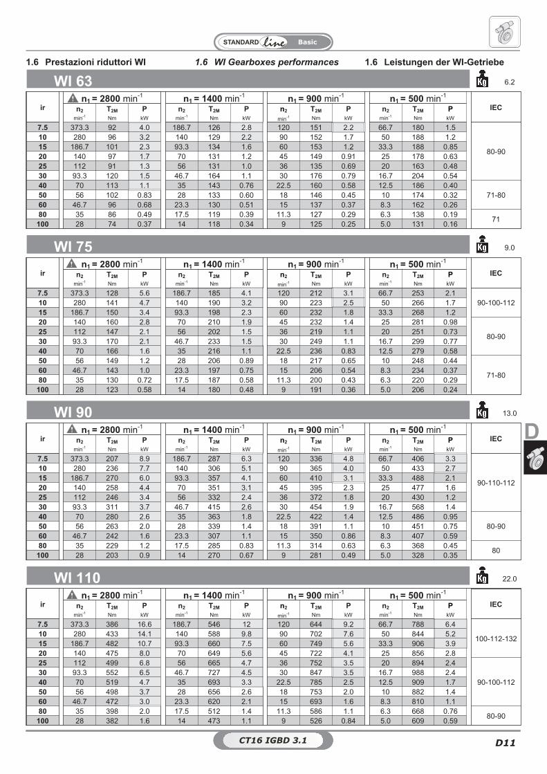
1.6 WI Gearboxes performances 1.6 Leistungen der WI-Getriebe1.6 Prestazioni riduttori WI
WI 63 6.2
irn1 = 2800 min-1 n1 = 1400 min-1 n1 = 900 min-1 n1 = 500 min-1
IECn2 T2M P n2 T2M P n2 T2M P n2 T2M Pmin-1 Nm kW min-1 Nm kW min-1 Nm kW min-1 Nm kW
7.5 373.3 92 4.0 186.7 126 2.8 120 151 2.2 66.7 180 1.5
80-90
10 280 96 3.2 140 129 2.2 90 152 1.7 50 188 1.215 186.7 101 2.3 93.3 134 1.6 60 153 1.2 33.3 188 0.8520 140 97 1.7 70 131 1.2 45 149 0.91 25 178 0.6325 112 91 1.3 56 131 1.0 36 135 0.69 20 163 0.4830 93.3 120 1.5 46.7 164 1.1 30 176 0.79 16.7 204 0.5440 70 113 1.1 35 143 0.76 22.5 160 0.58 12.5 186 0.40
71-8050 56 102 0.83 28 133 0.60 18 146 0.45 10 174 0.3260 46.7 96 0.68 23.3 130 0.51 15 137 0.37 8.3 162 0.2680 35 86 0.49 17.5 119 0.39 11.3 127 0.29 6.3 138 0.19
71100 28 74 0.37 14 118 0.34 9 125 0.25 5.0 131 0.16
WI 75 9.0
irn1 = 2800 min-1 n1 = 1400 min-1 n1 = 900 min-1 n1 = 500 min-1
IECn2 T2M P n2 T2M P n2 T2M P n2 T2M Pmin-1 Nm kW min-1 Nm kW min-1 Nm kW min-1 Nm kW
7.5 373.3 128 5.6 186.7 185 4.1 120 212 3.1 66.7 253 2.190-100-11210 280 141 4.7 140 190 3.2 90 223 2.5 50 266 1.7
15 186.7 150 3.4 93.3 198 2.3 60 232 1.8 33.3 268 1.220 140 160 2.8 70 210 1.9 45 232 1.4 25 281 0.98
80-9025 112 147 2.1 56 202 1.5 36 219 1.1 20 251 0.7330 93.3 170 2.1 46.7 233 1.5 30 249 1.1 16.7 299 0.7740 70 166 1.6 35 216 1.1 22.5 236 0.83 12.5 279 0.5850 56 149 1.2 28 206 0.89 18 217 0.65 10 248 0.44
71-8060 46.7 143 1.0 23.3 197 0.75 15 206 0.54 8.3 234 0.3780 35 130 0.72 17.5 187 0.58 11.3 200 0.43 6.3 220 0.29
100 28 123 0.58 14 180 0.48 9 191 0.36 5.0 206 0.24
WI 90 13.0
irn1 = 2800 min-1 n1 = 1400 min-1 n1 = 900 min-1 n1 = 500 min-1
IECn2 T2M P n2 T2M P n2 T2M P n2 T2M Pmin-1 Nm kW min-1 Nm kW min-1 Nm kW min-1 Nm kW
7.5 373.3 207 8.9 186.7 287 6.3 120 336 4.8 66.7 406 3.3
90-110-112
10 280 236 7.7 140 306 5.1 90 365 4.0 50 433 2.715 186.7 270 6.0 93.3 357 4.1 60 410 3.1 33.3 488 2.120 140 258 4.4 70 351 3.1 45 395 2.3 25 477 1.625 112 246 3.4 56 332 2.4 36 372 1.8 20 430 1.230 93.3 311 3.7 46.7 415 2.6 30 454 1.9 16.7 568 1.440 70 280 2.6 35 363 1.8 22.5 422 1.4 12.5 486 0.95
80-9050 56 263 2.0 28 339 1.4 18 391 1.1 10 451 0.7560 46.7 242 1.6 23.3 307 1.1 15 350 0.86 8.3 407 0.5980 35 229 1.2 17.5 285 0.83 11.3 314 0.63 6.3 368 0.45
80100 28 203 0.9 14 270 0.67 9 281 0.49 5.0 328 0.35
WI 110 22.0
irn1 = 2800 min-1 n1 = 1400 min-1 n1 = 900 min-1 n1 = 500 min-1
IECn2 T2M P n2 T2M P n2 T2M P n2 T2M Pmin-1 Nm kW min-1 Nm kW min-1 Nm kW min-1 Nm kW
7.5 373.3 386 16.6 186.7 546 12 120 644 9.2 66.7 788 6.4
100-112-13210 280 433 14.1 140 588 9.8 90 702 7.6 50 844 5.215 186.7 482 10.7 93.3 660 7.5 60 749 5.6 33.3 906 3.920 140 475 8.0 70 649 5.6 45 722 4.1 25 856 2.825 112 499 6.8 56 665 4.7 36 752 3.5 20 894 2.4
90-100-11230 93.3 552 6.5 46.7 727 4.5 30 847 3.5 16.7 988 2.440 70 519 4.7 35 693 3.3 22.5 785 2.5 12.5 909 1.750 56 498 3.7 28 656 2.6 18 753 2.0 10 882 1.460 46.7 472 3.0 23.3 620 2.1 15 693 1.6 8.3 810 1.180 35 398 2.0 17.5 512 1.4 11.3 586 1.1 6.3 668 0.76
80-90100 28 382 1.6 14 473 1.1 9 526 0.84 5.0 609 0.59
CT16 IGBD 3.0CT16 IGBD 3.1
CT16 IGBD 3.0D12
Basic
WI 130 48.0
irn1 = 2800 min-1 n1 = 1400 min-1 n1 = 900 min-1 n1 = 500 min-1
IECn2 T2M P n2 T2M P n2 T2M P n2 T2M Pmin-1 Nm kW min-1 Nm kW min-1 Nm kW min-1 Nm kW
7.5 373.3 514 22.1 186.7 741 16.1 120 871 12.3 66.7 1071 8.6
13210 280 574 18.7 140 820 13.5 90 951 10.3 50 1153 7.115 186.7 669 14.7 93.3 917 10.3 60 1055 7.8 33.3 1293 5.520 140 660 11 70 905 7.8 45 1022 5.8 25 1222 4.025 112 660 9.0 56 931 6.5 36 1031 4.8 20 1192 3.2
100-112-13230 93.3 774 9.0 46.7 1047 6.4 30 1152 4.7 16.7 1378 3.340 70 727 6.5 35 1043 4.9 22.5 1099 3.5 12.5 1284 2.450 56 696 5.1 28 972 3.8 18 1017 2.7 10 1216 1.9
100-11260 46.7 638 4.0 23.3 928 3.1 15 923 2.1 8.3 1105 1.580 35 606 3.0 17.5 853 2.3 11.3 852 1.6 6.3 967 1.1
90-100-112100 28 525 2.2 14 742 1.7 9 751 1.2 5.0 877 0.85
1.6 WI Gearboxes performances 1.6 Leistungen der WI-Getriebe1.6 Prestazioni riduttori WI
NOTE. Please pay attention to the framearound the input power value: for thisgearboxes it’s important to check thethermal capacity (comp. chapter 1.7-A). Fordetails please contact our technical
HINWEIS. Sind in den TabellenNennleistungen eingerahmt, so ist diethermische Leistungsgrenze der Getriebezu beachten (s. S. 1.7-A).Für weitere Informationen wenden Sie sich
N.B. Per i riduttori evidenziati dal doppiobordo nella colonna delle potenze ènecessario verificare lo scambio termicodel riduttore (come nel par. 1.7-A). Permaggiori informazioni contattare l’ufficio
Listed weights are for reference only and can
vary according to the gearbox version.Die angegebenen Gewichte sind Richtwerte undkönnen je nach Getriebeversion etwas variieren.
I pesi riportati sono indicativi e possono variarein funzione della versione del riduttore.
ATTENZIONE! WARNING! ACHTUNG!Per situazioni con velocità di ingressoparticolari attenersi alla tabella sottoriportata che evidenzia situazioni criticheper ogni riduttore (Vedere paragrafo
If in presence of non standard input speedplease attain to the chart below consideringextreme usage conditions for eachgearbox (Look at chapter 1.2-A).
Mit unstandardisierteAntriebsgeschwindigkeit bitte auf folgendeListe Bezug nehmen in Betrachtung derschwierigen Arbeitsbedingungen fuer jede
UI - RI - WI
25 28 30 40 50 63 70 75 85 90 110 130 150 180
1500 < n1 < 3000 OK OK OK OK OK Contattare il ns. servizio tecnicoContact our technical dept
Wenden Sie sich an unseren technischen Servicen1 > 3000
WI 150 84.0
irn1 = 2800 min-1 n1 = 1400 min-1 n1 = 900 min-1 n1 = 500 min-1
IECn2 T2M P n2 T2M P n2 T2M P n2 T2M Pmin-1 Nm kW min-1 Nm kW min-1 Nm kW min-1 Nm kW
7.5
-
186.7 1200 25.5
- -
16010 140 1240 19.515 93.3 1250 13.520 70 1300 10.5 132-16025 56 1200 8.8
13230 46.7 1200 7.440 35 1550 7.450 28 1400 5.5 100-112-13260 23.3 1260 4.4
100-11280 17.5 1150 3.2100 14 1000 2.4
CT16 IGBD 3.0CT16 IGBD 3.1
CT16 IGBD 3.0 D13
Basic
D
FA
80
9
3
10.4
9
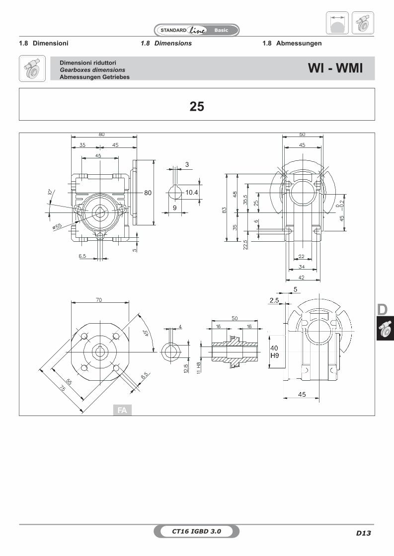
1.8 Dimensions1.8 Dimensioni 1.8 Abmessungen
Dimensioni riduttoriGearboxes dimensions
Abmessungen GetriebesWI - WMI
25
CT16 IGBD 3.0D14
Basic
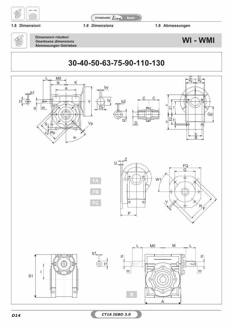
1.8 Dimensions1.8 Dimensioni 1.8 Abmessungen
Dimensioni riduttoriGearboxes dimensions
Abmessungen GetriebesWI - WMI
30-40-50-63-75-90-110-130
B
a
M0
S
L
M L
d
m m
d
M0L
I
d m
m
Vp
Fp
wRp
fE2
E1h
HE
1
bB
tyY
Dy
b2
by
D
CC
G
ZU
V
W1
FQ
FR
Gp
Pp PpC C
t2
P
b1
t1
b1
t1
A
S1
KN
FA
FB
FC
I
CT16 IGBD 3.0 D15
Basic
D
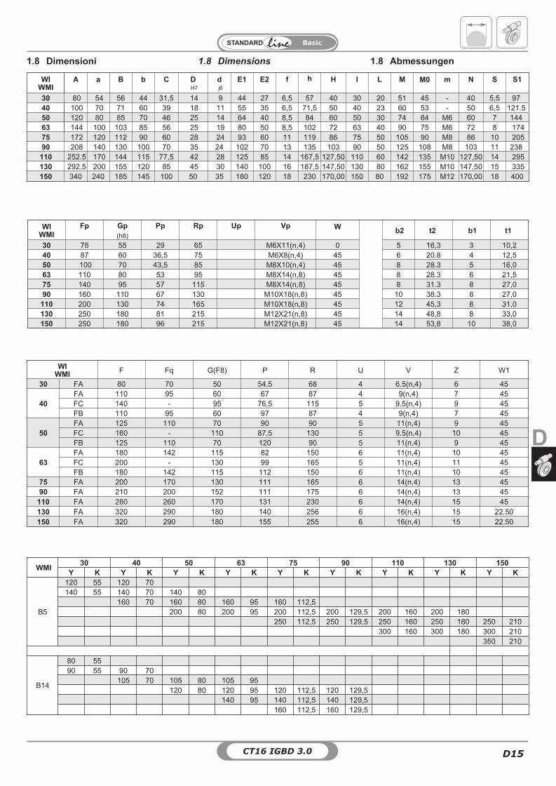
WIWMI
A a B b C DH7
dj6
E1 E2 f h H I L M M0 m N S S1
30 80 54 56 44 31,5 14 9 44 27 6,5 57 40 30 20 51 45 - 40 5,5 9740 100 70 71 60 39 18 11 55 35 6,5 71,5 50 40 23 60 53 - 50 6,5 121.550 120 80 85 70 46 25 14 64 40 8,5 84 60 50 30 74 64 M6 60 7 14463 144 100 103 85 56 25 19 80 50 8,5 102 72 63 40 90 75 M6 72 8 17475 172 120 112 90 60 28 24 93 60 11 119 86 75 50 105 90 M8 86 10 20590 208 140 130 100 70 35 24 102 70 13 135 103 90 50 125 108 M8 103 11 238
110 252.5 170 144 115 77,5 42 28 125 85 14 167,5 127,50 110 60 142 135 M10 127,50 14 295130 292.5 200 155 120 85 45 30 140 100 16 187,5 147,50 130 80 162 155 M10 147,50 15 335150 340 240 185 145 100 50 35 180 120 18 230 170,00 150 80 192 175 M12 170,00 18 400
WIWMI
Fp Gp(h8)
Pp Rp Up Vp W b2 t2 b1 t1
30 75 55 29 65 M6X11(n,4) 0 5 16,3 3 10,240 87 60 36,5 75 M6X8(n,4) 45 6 20.8 4 12,550 100 70 43,5 85 M8X10(n,4) 45 8 28.3 5 16,063 110 80 53 95 M8X14(n,8) 45 8 28.3 6 21,575 140 95 57 115 M8X14(n,8) 45 8 31.3 8 27,090 160 110 67 130 M10X18(n,8) 45 10 38.3 8 27,0
110 200 130 74 165 M10X18(n,8) 45 12 45,3 8 31,0130 250 180 81 215 M12X21(n,8) 45 14 48,8 8 33,0150 250 180 96 215 M12X21(n,8) 45 14 53,8 10 38,0
WIWMI F Fq G(F8) P R U V Z W1
30 FA 80 70 50 54,5 68 4 6.5(n,4) 6 45
40FA 110 95 60 67 87 4 9(n,4) 7 45FC 140 - 95 76,5 115 5 9.5(n,4) 9 45FB 110 95 60 97 87 4 9(n,4) 7 45
50FA 125 110 70 90 90 5 11(n,4) 9 45FC 160 - 110 87,5 130 5 9.5(n,4) 10 45FB 125 110 70 120 90 5 11(n,4) 9 45
63FA 180 142 115 82 150 6 11(n,4) 10 45FC 200 - 130 99 165 5 11(n,4) 11 45FB 180 142 115 112 150 6 11(n,4) 10 45
75 FA 200 170 130 111 165 6 14(n,4) 13 4590 FA 210 200 152 111 175 6 14(n,4) 13 45
110 FA 280 260 170 131 230 6 14(n,4) 15 45
130 FA 320 290 180 140 256 6 16(n,4) 15 22.50
150 FA 320 290 180 155 255 6 16(n,4) 15 22.50
1.8 Dimensions1.8 Dimensioni 1.8 Abmessungen
WMI30 40 50 63 75 90 110 130 150
Y K Y K Y K Y K Y K Y K Y K Y K Y K
B5
120 55 120 70140 55 140 70 140 80
160 70 160 80 160 95 160 112,5200 80 200 95 200 112,5 200 129,5 200 160 200 180
250 112,5 250 129,5 250 160 250 180 250 210300 160 300 180 300 210
350 210
B14
80 5590 55 90 70
105 70 105 80 105 95120 80 120 95 120 112,5 120 129,5
140 95 140 112,5 140 129,5160 112,5 160 129,5
CT16 IGBD 3.0D16
Basic
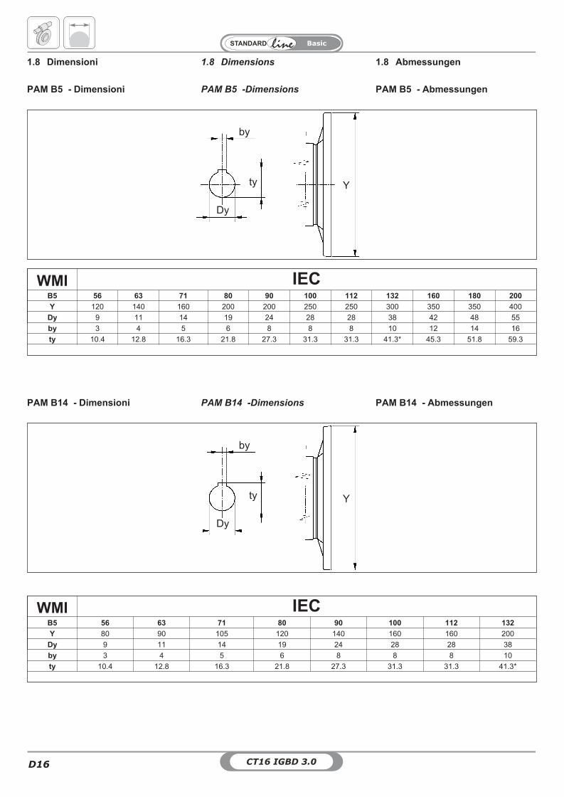
WMI IECB5 56 63 71 80 90 100 112 132 160 180 200
Y 120 140 160 200 200 250 250 300 350 350 400
Dy 9 11 14 19 24 28 28 38 42 48 55
by 3 4 5 6 8 8 8 10 12 14 16
ty 10.4 12.8 16.3 21.8 27.3 31.3 31.3 41.3* 45.3 51.8 59.3
* WMI 130 ty=40.3 (IEC 132)
1.8 Dimensions1.8 Dimensioni 1.8 Abmessungen
PAM B5 -DimensionsPAM B5 - Dimensioni PAM B5 - Abmessungen
ty
by
Dy
Y
PAM B14 -DimensionsPAM B14 - Dimensioni PAM B14 - Abmessungen
WMI IECB5 56 63 71 80 90 100 112 132
Y 80 90 105 120 140 160 160 200
Dy 9 11 14 19 24 28 28 38
by 3 4 5 6 8 8 8 10
ty 10.4 12.8 16.3 21.8 27.3 31.3 31.3 41.3*
* WMI 130 ty=40.3 (IEC 132)
ty
by
Dy
Y
CT16 IGBD 3.0 D17
Basic
D
D19
D18
BRSAL VKLALBU PROT
CT16 IGBD 3.0D18
Basic
d1 R
H
d1
m Lm
RaRb
YL
WMIWI
D
C C
T T
C C
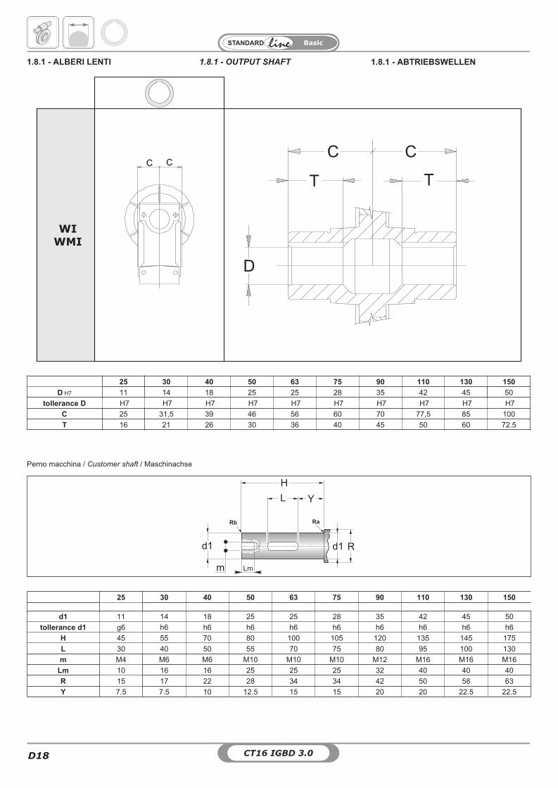
1.8.1 - ALBERI LENTI 1.8.1 - ABTRIEBSWELLEN1.8.1 - OUTPUT SHAFT
25 30 40 50 63 75 90 110 130 150
d1 11 14 18 25 25 28 35 42 45 50
tollerance d1 g6 h6 h6 h6 h6 h6 h6 h6 h6 h6
H 45 55 70 80 100 105 120 135 145 175
L 30 40 50 55 70 75 80 95 100 130
m M4 M6 M6 M10 M10 M10 M12 M16 M16 M16
Lm 10 16 16 25 25 25 32 40 40 40
R 15 17 22 28 34 34 42 50 58 63
Y 7.5 7.5 10 12.5 15 15 20 20 22.5 22.5
25 30 40 50 63 75 90 110 130 150
D H7 11 14 18 25 25 28 35 42 45 50
tollerance D H7 H7 H7 H7 H7 H7 H7 H7 H7 H7
C 25 31,5 39 46 56 60 70 77,5 85 100
T 16 21 26 30 36 40 45 50 60 72.5
Perno macchina / Customer shaft / Maschinachse
CT16 IGBD 3.0 D19
Basic
D
All worm gearboxes aresupplied with hollow output shaft. Outputshafts as shown in the size drawings can besupplied upon request.
Sizes of feathers comply with standardsUNI 6604-69.
Alle Schneckengetriebe werden mit hohlerAbtriebswelle geliefert. Auf Anfrage könnenAbtriebswellen gemäß den Maßzeich-nungen geliefert werden.
Die Abmessungen der Federn entsprechenden Normen UNI 6604-69.
Tutti i riduttori a vite senza finesono forniti con albero lento cavo.A richiesta, possono essere forniti alberilenti come indicato nei disegnidimensionali.Le dimensioni delle linguette sono conformialle norme UNI 6604-69.
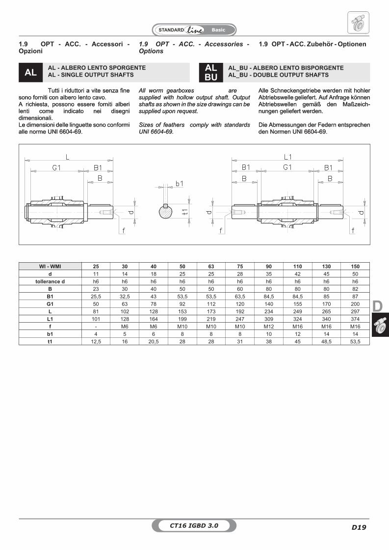
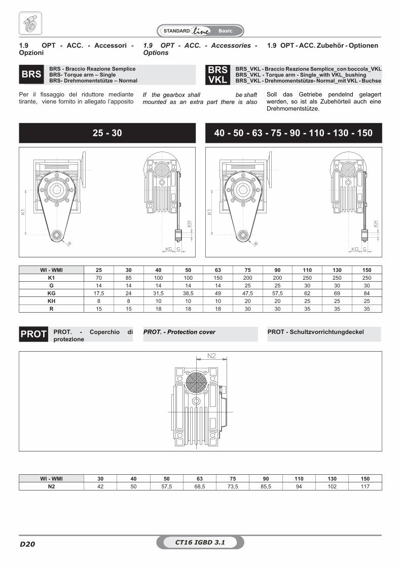
1.9 OPT - ACC. - Accessories -Options
1.9 OPT - ACC. - Accessori -Opzioni
1.9 OPT - ACC. Zubehör - Optionen
All worm gearboxes aresupplied with hollow output shaft. Outputshafts as shown in the size drawings can besupplied upon request.
Sizes of feathers comply with standardsUNI 6604-69.
Alle Schneckengetriebe werden mit hohlerAbtriebswelle geliefert. Auf Anfrage könnenAbtriebswellen gemäß den Maßzeich-nungen geliefert werden.
Die Abmessungen der Federn entsprechenden Normen UNI 6604-69.
Tutti i riduttori a vite senza finesono forniti con albero lento cavo.A richiesta, possono essere forniti alberilenti come indicato nei disegnidimensionali.Le dimensioni delle linguette sono conformialle norme UNI 6604-69.
AL_BU - ALBERO LENTO BISPORGENTEAL_BU - DOUBLE OUTPUT SHAFTS
ALBU
AL - ALBERO LENTO SPORGENTEAL - SINGLE OUTPUT SHAFTSAL
WI - WMI 25 30 40 50 63 75 90 110 130 150
d 11 14 18 25 25 28 35 42 45 50
tollerance d h6 h6 h6 h6 h6 h6 h6 h6 h6 h6
B 23 30 40 50 50 60 80 80 80 82
B1 25,5 32,5 43 53,5 53,5 63,5 84,5 84,5 85 87
G1 50 63 78 92 112 120 140 155 170 200
L 81 102 128 153 173 192 234 249 265 297
L1 101 128 164 199 219 247 309 324 340 374
f - M6 M6 M10 M10 M10 M12 M16 M16 M16
b1 4 5 6 8 8 8 10 12 14 14
t1 12,5 16 20,5 28 28 31 38 45 48,5 53,5
CT16 IGBD 3.0D20
Basic
WI - WMI 25 30 40 50 63 75 90 110 130 150
K1 70 85 100 100 150 200 200 250 250 250
G 14 14 14 14 14 25 25 30 30 30
KG 17,5 24 31,5 38,5 49 47,5 57,5 62 69 84
KH 8 8 10 10 10 20 20 25 25 25
R 15 15 18 18 18 30 30 35 35 35
25 - 30 40 - 50 - 63 - 75 - 90 - 110 - 130 - 150
Per il fissaggio del riduttore mediantetirante, viene fornito in allegato l’apposito
If the gearbox shall be shaftmounted as an extra part there is also
Soll das Getriebe pendelnd gelagertwerden, so ist als Zubehörteil auch eineDrehmomentstütze.
1.9 OPT - ACC. - Accessories -Options
1.9 OPT - ACC. - Accessori -Opzioni
1.9 OPT - ACC. Zubehör - Optionen
PROT. - Protection cover PROT - SchultzvorrichtungdeckelPROT. - Coperchio diprotezione
PROT
WI - WMI 30 40 50 63 75 90 110 130 150
N2 42 50 57,5 68,5 73,5 85,5 94 102 117
CT16 IGBD 3.0CT16 IGBD 3.1
BRS_VKL - Braccio Reazione Semplice_con boccola_VKLBRS_VKL - Torque arm - Single_with VKL_bushingBRS_VKL - Drehmomentstütze- Normal_mit VKL - Buchse
BRSVKL
BRS - Braccio Reazione SempliceBRS- Torque arm – SingleBRS- Drehmomentstütze – Normal
BRS
CT16 IGBD 3.0 D21
Basic
D
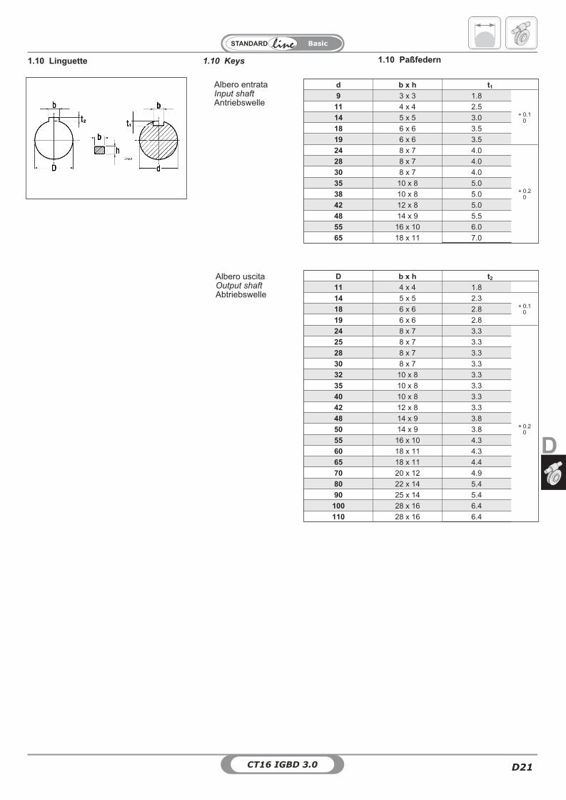
1.10 Keys 1.10 Paßfedern1.10 Linguette
Albero entrataInput shaftAntriebswelle
Albero uscitaOutput shaftAbtriebswelle
D b x h t2
11 4 x 4 1.8
14 5 x 5 2.3+ 0.1
018 6 x 6 2.8
19 6 x 6 2.8
24 8 x 7 3.3
25 8 x 7 3.3
+ 0.20
28 8 x 7 3.3
30 8 x 7 3.3
32 10 x 8 3.3
35 10 x 8 3.3
40 10 x 8 3.3
42 12 x 8 3.3
48 14 x 9 3.8
50 14 x 9 3.8
55 16 x 10 4.3
60 18 x 11 4.3
65 18 x 11 4.4
70 20 x 12 4.9
80 22 x 14 5.4
90 25 x 14 5.4
100 28 x 16 6.4
110 28 x 16 6.4
d b x h t1
9 3 x 3 1.8
+ 0.10
11 4 x 4 2.5
14 5 x 5 3.0
18 6 x 6 3.5
19 6 x 6 3.5
24 8 x 7 4.0
+ 0.20
28 8 x 7 4.0
30 8 x 7 4.0
35 10 x 8 5.0
38 10 x 8 5.0
42 12 x 8 5.0
48 14 x 9 5.5
55 16 x 10 6.0
65 18 x 11 7.0

CT16 IGBD 3.0D22
Basic
Recommended