CCHHAAPPTTEERR33 SSYYNNTTHHEESSIISS AANNDD CCHHAARRAACCTTEERRIISSAATTIIOONN OOFF NNAANNOOSSIIZZEEDD MMEETTAALL OOXXIIDDEESS ((RREESSUULLTTSS AANNDD DDIISSCCUUSSSSIIOONN))
118
3.1 A simple and effective method of the synthesis of αααα-Fe2O3 nanoparticles :
Iron oxides belong to the most abundant minerals and occur with a large variety of
stoichiometries, structures, and properties. The more important ones are FeO (wustite), λ-
Fe2O3 (maghemite), α-Fe2O3 (hematite), and Fe3O4 (magnetite) with rock-salt, vacancy rich
inverse spinel, corundum, and inverse spinel structures, respectively; the two former ones
being thermodynamically less favorable and α-Fe2O3 being the most oxidized one. Iron
oxides are widely used in industry as catalysts or catalyst supports. Metal-oxides constitute an
important class of materials that are involved in environmental science, electrochemistry,
biology, chemical sensors, magnetism and other fields. One of their most important
applications is heterogeneous catalysis. Heterogeneous catalysts based on magnetic mixed
iron oxides (MO-Fe2O3; M: Fe, Co, Cu, Mn) were used for the decolorization of several
synthetic dyes like bromophenol blue, chicago sky blue, Cu-phthalocyanine, eosin yellowish,
evans blue, naphthol blue black, phenol red, poly B-411, and reactive orange 16. All the
catalysts decomposed H2O2 yielding highly reactive hydroxyl radicals, and were able to
decolorize the synthetic dyes. The most effective catalyst FeO-Fe2O3 (25 mg mL-1 with 100
mmol L-1 H2O2) produced more than 90% decolorization of 50 mg L-1.bromophenol blue,
chicago sky blue, evans blue and naphthol blue black within 24 h [1-14]. Aluminium
stabilized mixed metal oxide of copper and iron serve as an active catalyst for the nitration of
benzene in solid–liquid phase reaction, using 69% nitric acid as a nitrating agent. The
reaction was carried out with 100% selectivity towards nitro benzene [15]. Titania- and iron
oxide-supported gold catalysts have been used for the hydrogenation of propyne [16]. Fe2O3,
Mn2O3, and calcined physical mixtures of both ferric and manganese oxides with alumina
and/or silica gel have been used for the catalytic dehydration of ethanol [17]. The catalytic
behaviour of α-Fe2O3-based catalysts has been investigated for the toluene ammoxidation
reaction [18]. Iron (III) hydroxide has been used for the photooxidation of 2-aminophenol in
aqueous solution [19]. The partial oxidation of propane to formaldehyde using uranium
mixed oxide catalysts has been performed. Outstanding results for the selective oxidation of
propane and propene to formaldehyde were obtained using Fe/U catalysts [20]. An efficient
and selective acylation of alcohols and amines employing carboxylic acids as acylating
agents has been done by the metal oxide containing activated carbon catalyst, Catalyst was
synthesized by carbonization of organic ion-exchangers after incorporation of Fe3+ ions with
exchangeable cations present in resin [21]. Dehydrogenation of ethylbenzene has been
studied using potassium-promoted iron oxide as catalyst [22]. The sensitized photocatalytic
CCHHAAPPTTEERR33 SSYYNNTTHHEESSIISS AANNDD CCHHAARRAACCTTEERRIISSAATTIIOONN OOFF NNAANNOOSSIIZZEEDD MMEETTAALL OOXXIIDDEESS ((RREESSUULLTTSS AANNDD DDIISSCCUUSSSSIIOONN))
119
degradation of mono-, di- and trichlorophenols with aqueous suspensions of α-Fe2O3 and α-
FeOOH has been reported [23]. The oxidative dehydrogenation of propane on α - Fe2O3 has
been done in the presence and absence of tetrachloro methane at 723K [24]. Intramolecular
condensation reactions of pentamethylene and hexamethylene glycols over iron oxide has
been studied [25]. Catalysts consisting of sodium-promoted silica gel-supported iron oxide
has been found to catalyze the gas phase epoxidation of propene by nitrous oxide.
Selectivities to propene oxide of 40–60% at propene conversions in the range of 6–12% were
observed [26]. The catalytic conversion of benzoic acid to phenol in the presence of water
and oxygen was studied in the vapor phase over nickel oxide on various supports, like iron
oxide and silica [27]. Fine particle iron oxide based aerogels have been used as catalyst for
the partial oxidation of methanol [28]. Oxidation of benzoic acid has been studied via Fenton-
like reaction using an innovative supported γ-FeOOH catalyst [29]. Iron oxide and iron
carbide have been used as catalyst for the dehydration of tertiary alcohols [30]. Selective
reduction of nitro groups in aromatic azo compounds has been done in the presence of an iron
oxide/hydroxide catalyst [31]. Reduction of aromatic nitro compounds with hydrazine
hydrate in the presence of an iron oxide hydroxide catalyst has also been studied [32].
Decolorization of synthetic dyes by hydrogen peroxide with heterogeneous catalysis by
mixed iron oxides has been studied [33-34]. Nanosized iron oxides have considerable
attention due to their unique magnetic properties (superparamagnetism, high coercivity, low
curie temperature, high magnetic susceptibility, non-toxicity, biocompatibility and low cost
of production, which allows their usage in various nanotechnology applications in a broad
range of disciplines. Magnetic nanoparticles are also important in biomedical applications
e.g. magnetic bioseparation [35], magnetic target drug delivery [36], hyperthermia [37],
magnetic resonance imaging [38], magnetofection [39]. These particles have an ability to
interact with various biological molecules in different ways due to their superparamagnetic
properties, high specific area and wide choice of surface functionalization. In the present
work we have synthesized α - Fe2O3 nanoparticles by simple aqueous precipitation using
ammonia as precipitating agent. This method involves a simple, cheap and one step process
for synthesis of Fe2O3 nanaoparticles. The obtained particles of Fe2O3 have size from 15-42
nm. The synthesized nanoparticles were characterized by XRD, TGA/DTA, Magnetic
susceptibility and TEM
CCHHAAPPTTEERR33 SSYYNNTTHHEESSIISS AANNDD CCHHAARRAACCTTEERRIISSAATTIIOONN OOFF NNAANNOOSSIIZZEEDD MMEETTAALL OOXXIIDDEESS ((RREESSUULLTTSS AANNDD DDIISSCCUUSSSSIIOONN))
120
3.1.1 Results and discussions:
X-ray studies:
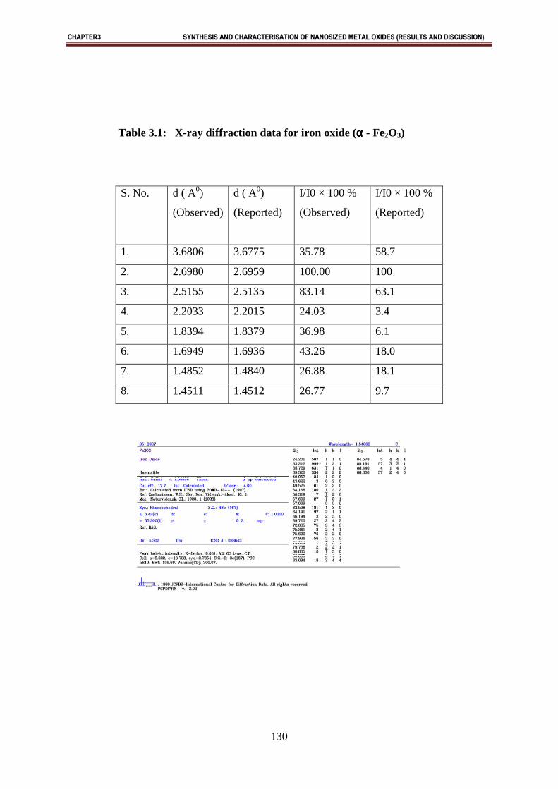
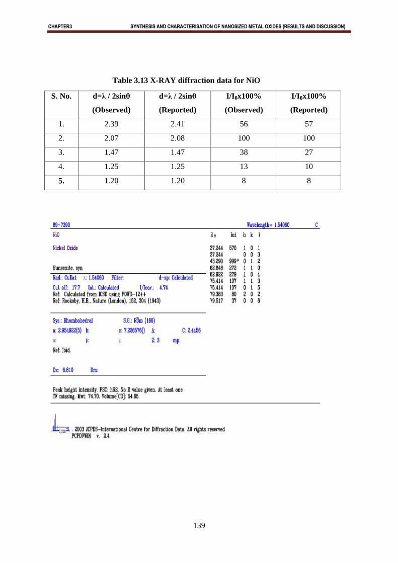
X-ray diffraction of synthesized oxide is shown in Figure (3.1). X-ray diffraction pattern of
pure iron oxide indicated that iron oxide is in the form of α - Fe2O3 [Fig- 1]. The X-ray
diffraction plot, shown in Fig. (3.1), shows peaks only due to α - Fe2O3 and no peak are
detected due to any other material or phase indicating a high degree of purity of the as-
synthesized sample. The broadening of the X-ray diffraction lines, as seen in the figure
reflects the nano-particle nature of the sample. In X-ray diffraction, some prominent peaks
were considered and corresponding d-values were compared with the standard [JCPDS file
No. 85-0987] [Table-3.1]. X-ray diffraction shows that metal oxide is pure α - Fe2O3 having
rhombohedral structure. Sharpness of the peaks shows good crystal growth of the oxide
particles. Average particle size (t) of the particles have been calculated using from high
intensity peak using the Debye-Scherrer equation
t = Kλ/ B cos θ
Where t is the average crystallite size of the phase under investigation, K is the Scherrer
constant (0.89), λ is the wave length of X – ray beam used, B is the full-with half maximum
(FWHM) of diffraction (in radians) and θ is the Bragg’s angle
The average crystallite size calculated is 35 nm which is in close agreement with the
TEM results.
Magnetic measurements:
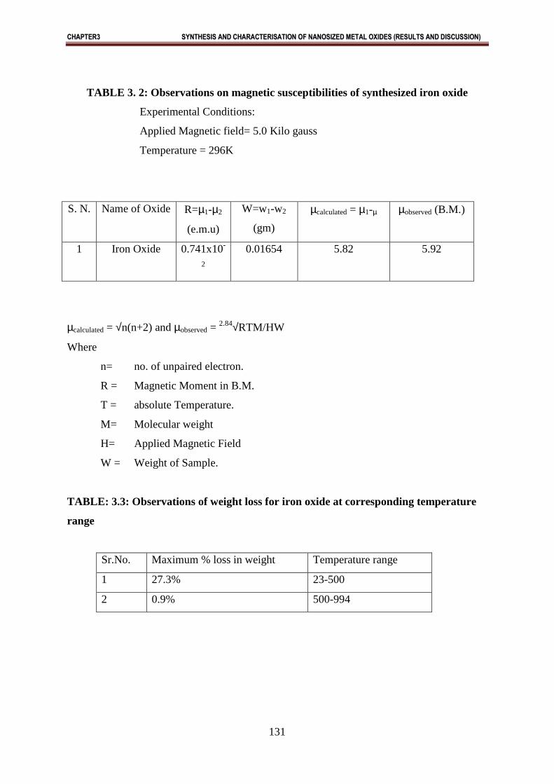
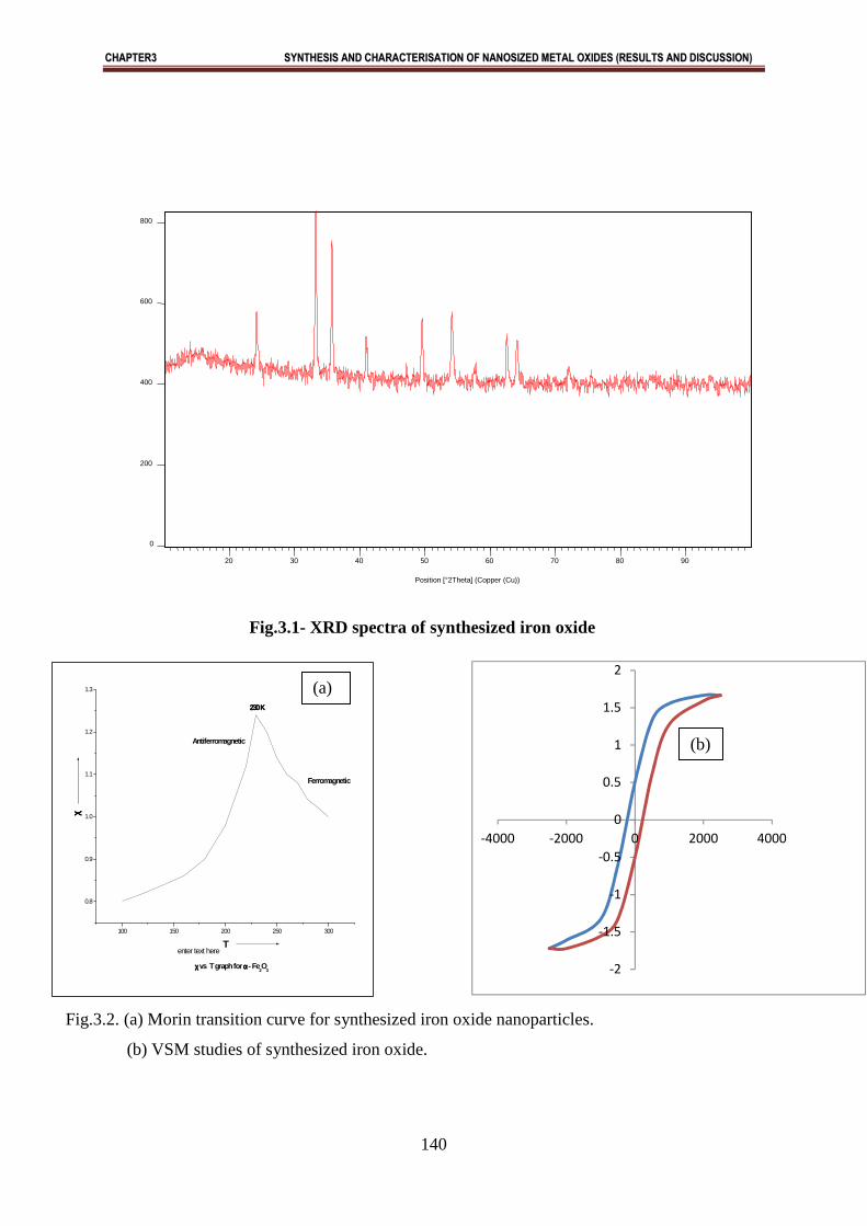
The magnetic moment for iron oxide was carried out at room temperature and was observed
as 5.68 B.M. This value of magnetic moment supports the fact that the synthesized iron oxide
is in the form of Fe2O3 with actual magnetic moment 5.92 B.M. This indicates the presence
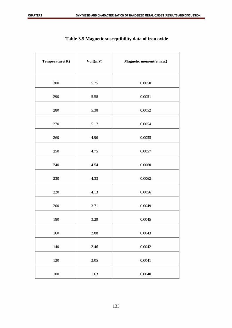
of 5 unpaired electrons in Fe2O3. Magnetic measurements were also carried out at
temperatures ranging from 300K to 100K to determine the temperature of morin transition.
The results are shown in Fig.3. 2(a) and have been reported in Table 3.2. VSM studies were
carried out at 300K to show hysteresis behavior of nanosized particles and it has been
observed that Fe2O3 show ferromagnetic behavior in nanocrystalline form. Ms value being
0.17 emu/g (Fig3.2b).
CCHHAAPPTTEERR33 SSYYNNTTHHEESSIISS AANNDD CCHHAARRAACCTTEERRIISSAATTIIOONN OOFF NNAANNOOSSIIZZEEDD MMEETTAALL OOXXIIDDEESS ((RREESSUULLTTSS AANNDD DDIISSCCUUSSSSIIOONN))
121
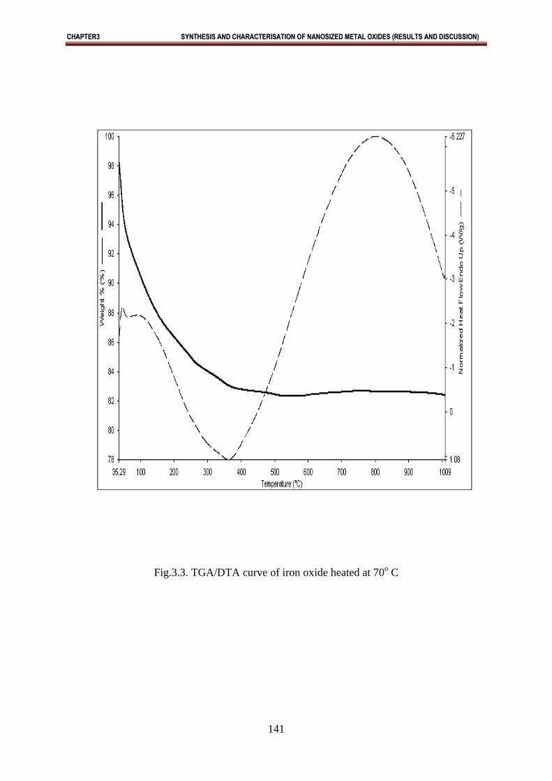
TGA/DTA studies:
TGA/DTA transition shows an endothermic peak at 3640 C [Fig.3.3]. It simply indicates that when FeO
(OH) is heated, it takes an amount of energy and 1.5 water molecules are removed. So, TGA curve
shows that for the formation of iron oxide temperature above 3640C is required (Fig. 3.3).
Surface Area Measurement:
The BET surface area of the samples was measured by nitrogen adsorption isotherms.
Surface area of the metal oxide was 27 m2/g. Samples were activated at 473 K for 4 h prior
to the measurement.
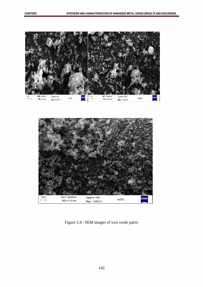
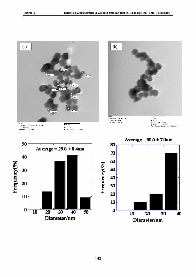
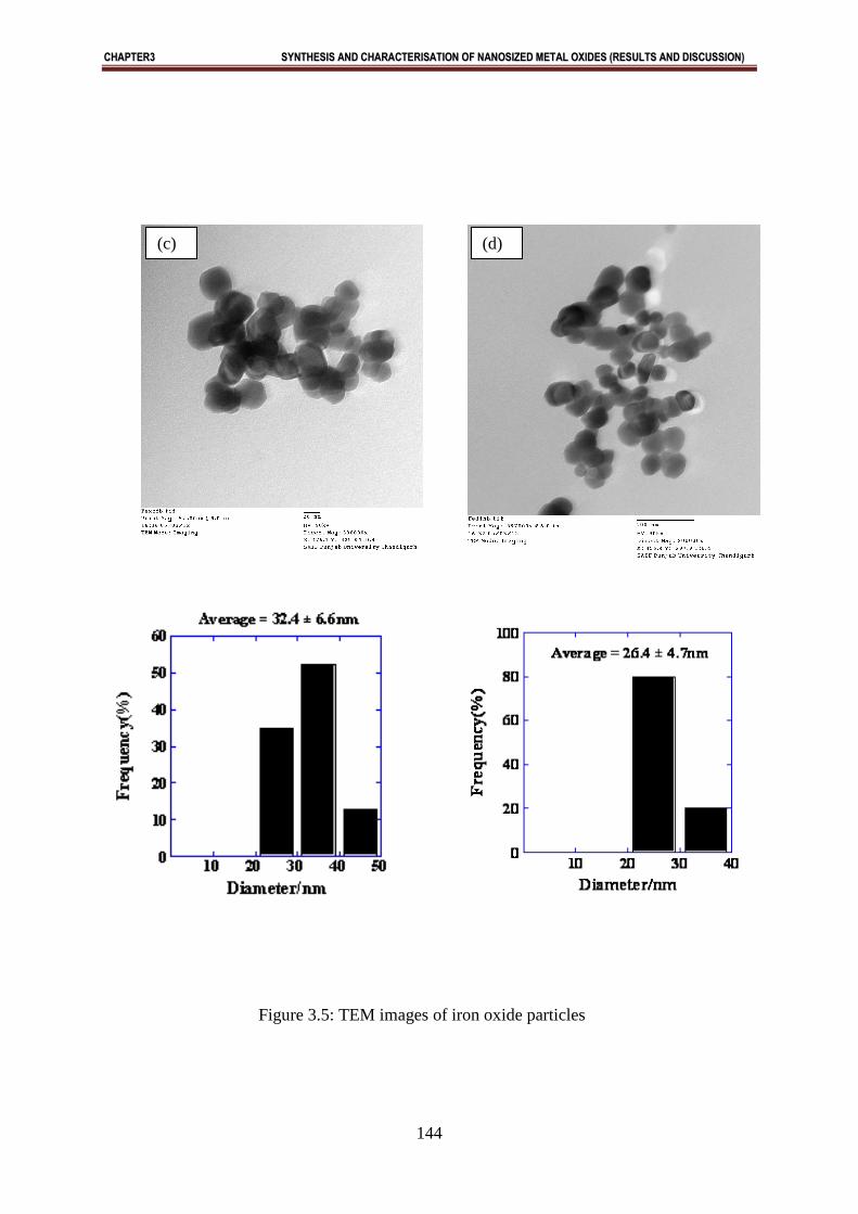
SEM/ TEM studies
Morphology of the sample was investigated using SEM and TEM. Fig.3.4 shows typical SEM images
of the sample.TEM studies were carried out to find out exact particle size of synthesized Fe2O3. Figure
3.5 shows the TEM image of the synthesized α - Fe2O3 nanoparticles. TEM images show that Fe2O3
nanoparticles are having particle size in the range of 15nm - 49 nm [Fig. 3.5]. The size distribution
histograms for nanoparticles provided their respective sizes as 29.8 ± 8.4 nm [Fig. 3.5a], 30.6 ± 7.0 nm
[Fig. 3.5b], 26.4 ± 4.7 nm [Fig. 3.5c], 32.4 ± 6.6 nm [Fig. 3.5d], respectively.
Abstract:
α - Fe2O3 nanoparticles with rhombohedral structure are synthesized successfully by aqueous
precipitation method. From TEM study, it is found that particles are with having size of 15-49 nm.
Magnetic measurements shows that α - Fe2O3 has five unpaired electron and hence paramagnetic
in nature. XRD studies show that iron oxide was formed as α- Fe2O3 instead of the commonly
formed magnetite nanoparticles Fe3O4 or a mixture of magnetite and maghemite. This method is
advantageous over the existing methods of synthesis of nanoparticles because other methods
require specialized instrumentation, highly skilled labour, expensive materials and methods.
Therefore, the proposed precipitation method is very promising and may have extensive
applications for the synthesis of nanosized iron oxide particles.
CCHHAAPPTTEERR33 SSYYNNTTHHEESSIISS AANNDD CCHHAARRAACCTTEERRIISSAATTIIOONN OOFF NNAANNOOSSIIZZEEDD MMEETTAALL OOXXIIDDEESS ((RREESSUULLTTSS AANNDD DDIISSCCUUSSSSIIOONN))
122
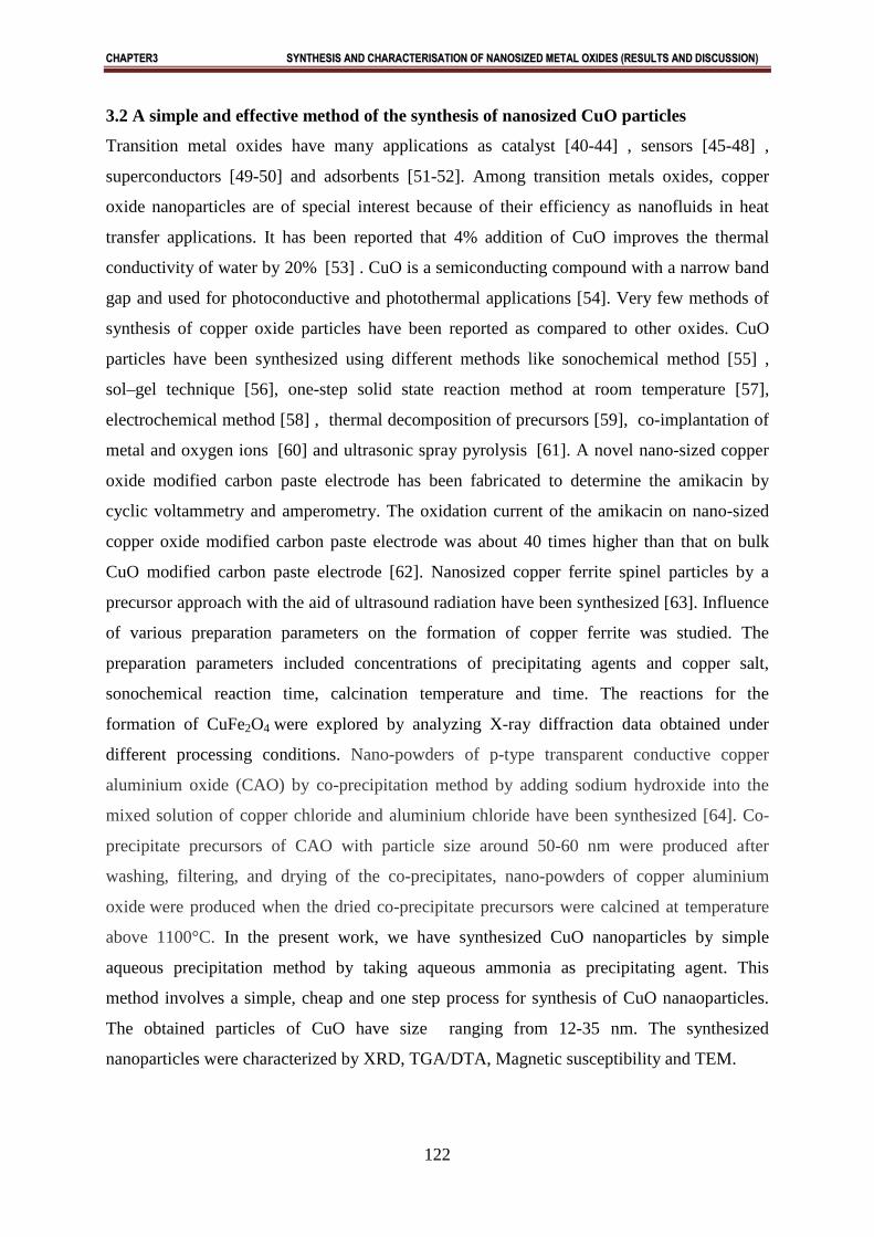
3.2 A simple and effective method of the synthesis of nanosized CuO particles
Transition metal oxides have many applications as catalyst [40-44] , sensors [45-48] ,
superconductors [49-50] and adsorbents [51-52]. Among transition metals oxides, copper
oxide nanoparticles are of special interest because of their efficiency as nanofluids in heat
transfer applications. It has been reported that 4% addition of CuO improves the thermal
conductivity of water by 20% [53] . CuO is a semiconducting compound with a narrow band
gap and used for photoconductive and photothermal applications [54]. Very few methods of
synthesis of copper oxide particles have been reported as compared to other oxides. CuO
particles have been synthesized using different methods like sonochemical method [55] ,
sol–gel technique [56], one-step solid state reaction method at room temperature [57],
electrochemical method [58] , thermal decomposition of precursors [59], co-implantation of
metal and oxygen ions [60] and ultrasonic spray pyrolysis [61]. A novel nano-sized copper
oxide modified carbon paste electrode has been fabricated to determine the amikacin by
cyclic voltammetry and amperometry. The oxidation current of the amikacin on nano-sized
copper oxide modified carbon paste electrode was about 40 times higher than that on bulk
CuO modified carbon paste electrode [62]. Nanosized copper ferrite spinel particles by a
precursor approach with the aid of ultrasound radiation have been synthesized [63]. Influence
of various preparation parameters on the formation of copper ferrite was studied. The
preparation parameters included concentrations of precipitating agents and copper salt,
sonochemical reaction time, calcination temperature and time. The reactions for the
formation of CuFe2O4 were explored by analyzing X-ray diffraction data obtained under
different processing conditions. Nano-powders of p-type transparent conductive copper
aluminium oxide (CAO) by co-precipitation method by adding sodium hydroxide into the
mixed solution of copper chloride and aluminium chloride have been synthesized [64]. Co-
precipitate precursors of CAO with particle size around 50-60 nm were produced after
washing, filtering, and drying of the co-precipitates, nano-powders of copper aluminium
oxide were produced when the dried co-precipitate precursors were calcined at temperature
above 1100°C. In the present work, we have synthesized CuO nanoparticles by simple
aqueous precipitation method by taking aqueous ammonia as precipitating agent. This
method involves a simple, cheap and one step process for synthesis of CuO nanaoparticles.
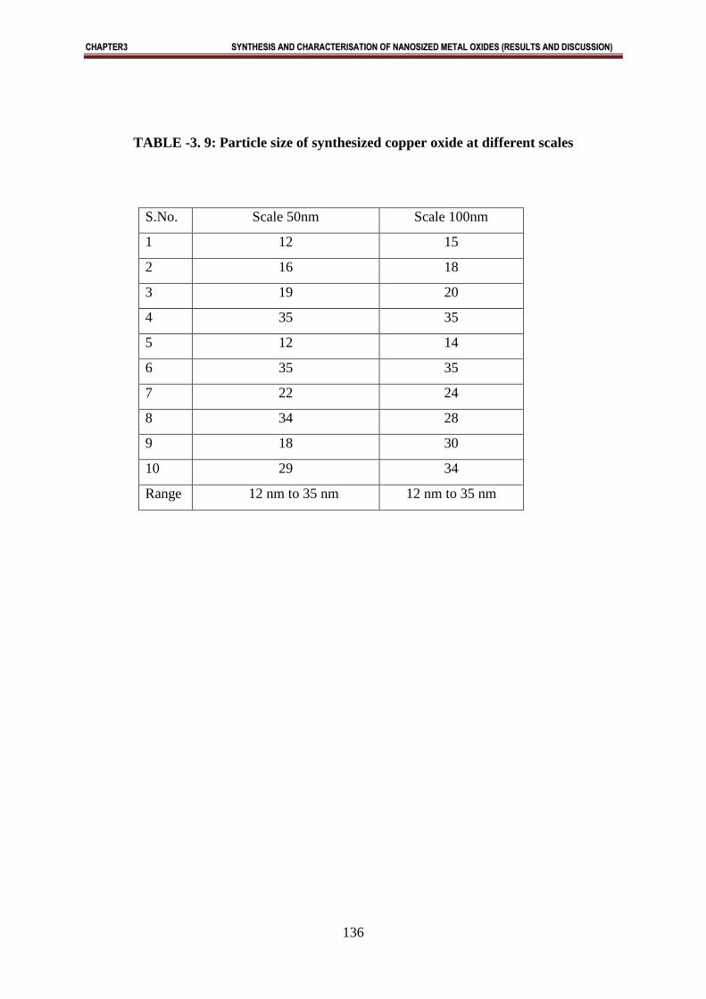
The obtained particles of CuO have size ranging from 12-35 nm. The synthesized
nanoparticles were characterized by XRD, TGA/DTA, Magnetic susceptibility and TEM.
CCHHAAPPTTEERR33 SSYYNNTTHHEESSIISS AANNDD CCHHAARRAACCTTEERRIISSAATTIIOONN OOFF NNAANNOOSSIIZZEEDD MMEETTAALL OOXXIIDDEESS ((RREESSUULLTTSS AANNDD DDIISSCCUUSSSSIIOONN))
123
3.2.1 Results and discussions:
X-ray studies:
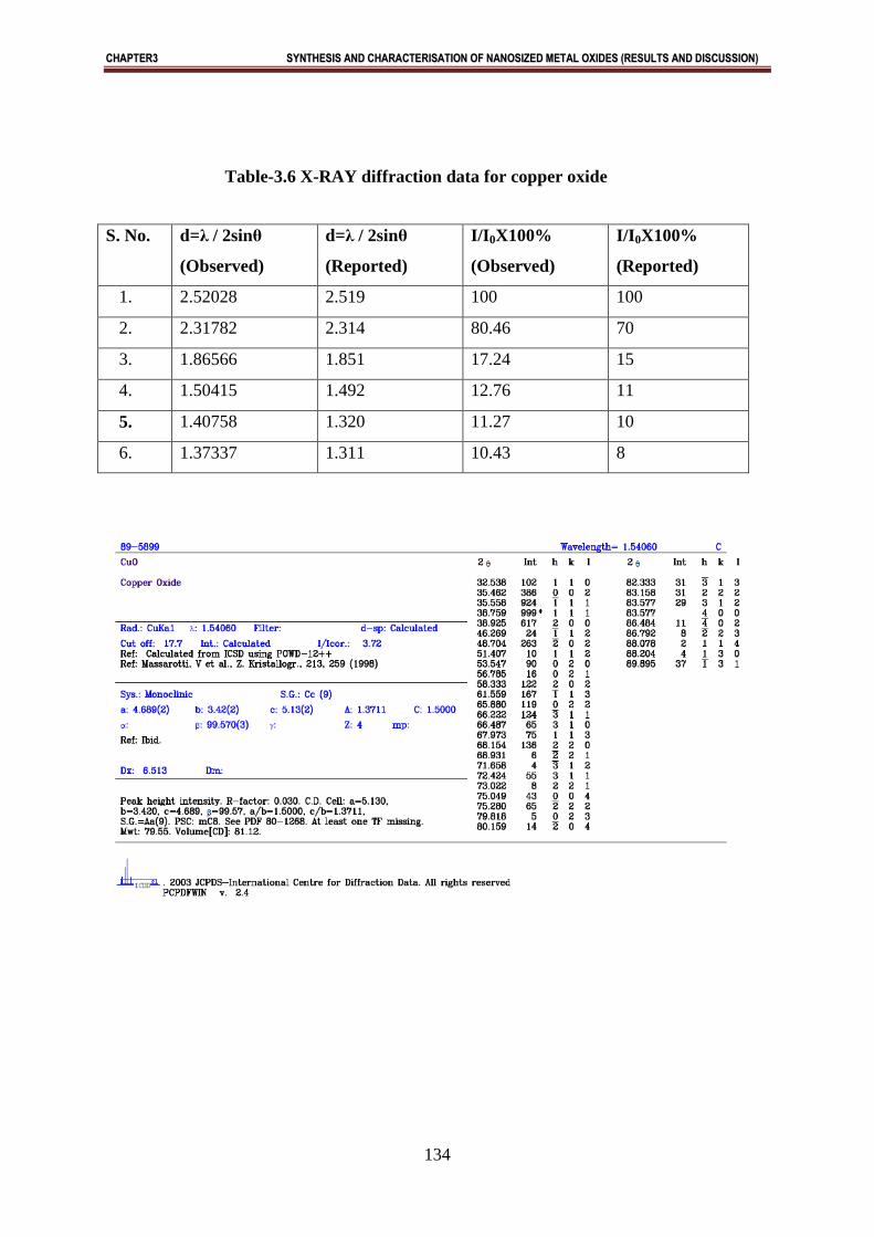
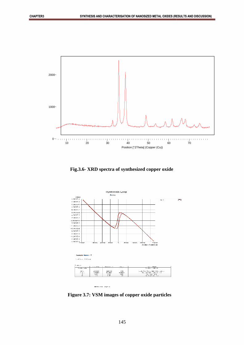
X-ray diffraction of synthesized oxide is shown in Figure (3.6). X-ray diffraction pattern of
pure copper oxide indicated that copper oxide is in the form of CuO Figure ( 3.6) . In X-ray
diffraction, some prominent peaks were considered and corresponding d-values (2.52028,
2.31782, 1.86566….) were compared with the standard [JCPDS file No. 05-661] (Table-3.6).
X-ray diffraction shows that metal oxide is pure CuO having monoclinic structure.
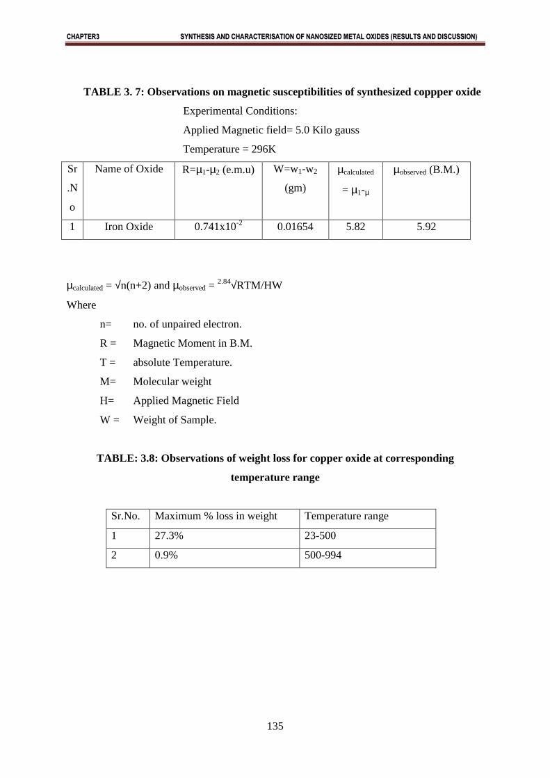
Magnetic measurements:
The magnetic moment for copper oxide is found to be 1.731 B.M. This value of magnetic
moment supports the fact that the formed copper oxide is in the form of CuO with actual
magnetic moment 1.732 B.M. This indicates that 1 unpaired electron is present in CuO (Fig.3.7).
Thus the oxide formed is paramagnetic in nature (Table 3.7).
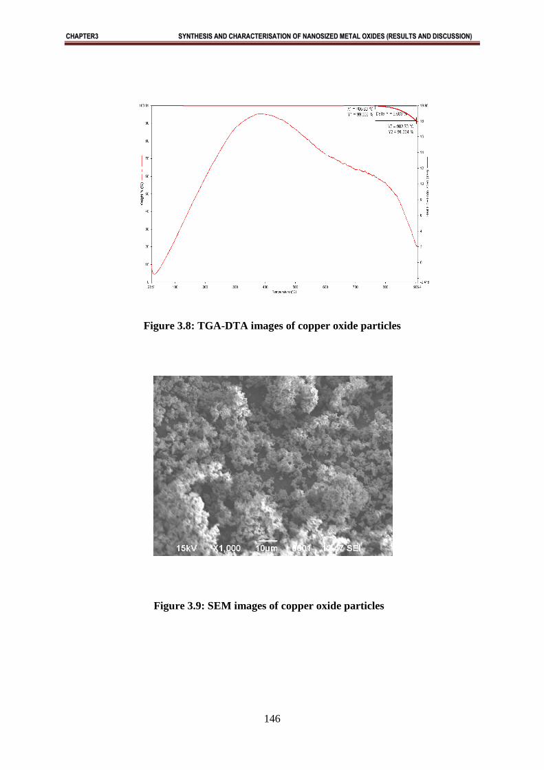
Thermal Analysis:
Thermal analysis includes a group of techniques in which a physical property of a substance
is measured as a function of temperature or time while the substance is subjected to a
controlled temperature programme. The analysis involves thermogravity (TG), differential
thermal analysis (DTA) and derivative Thermogravimetry (DTG). Thermal Gravimetric
studies of the calcined oxides prepared were done between a temperature range of 10-10000C
under N2 atmosphere. The TGA/DTA curves of the oxide is shown in Fig.3.8. The maximum
total weight loss observed for Copper oxide and their corresponding temperature is
summarized in Table (3.8). Results showed in the synthesized oxide undergoing
decomposition, dehydration or any physical change. From TGA curve we observed that
copper oxide show stable weight loss above 959.880C. In DTA curve also, there is
exothermic and endothermic peak which shows phase transition, solid state reach on any
chemical reaction occurred during heating treatment. From TGA curve we observed that
Copper Oxide showed stable weight loss above 959.880C [Fig.3.8].
SEM/TEM studies
Morphology of the sample was investigated using SEM and TEM. Fig.3. 9 shows typical
SEM images of the sample. TEM studies were performed to find out exact particle size of
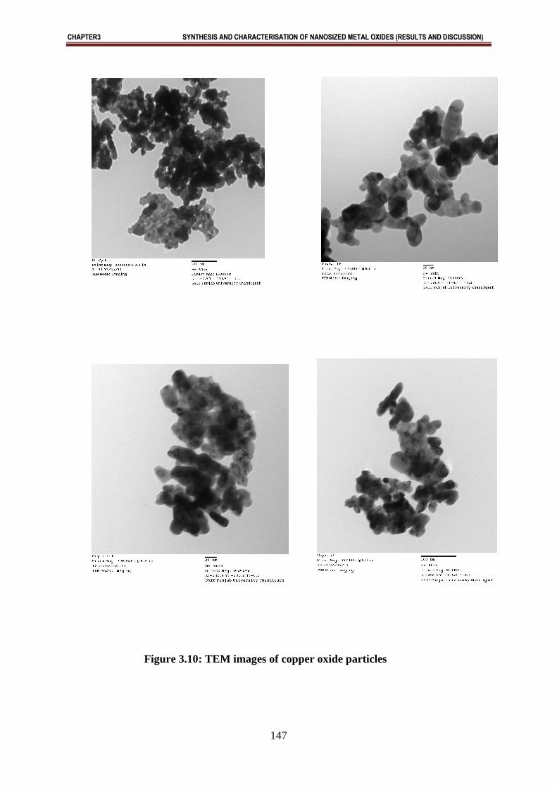
synthesized CuO. Figure (3.10) shows the TEM image of the synthesized CuO nanoparticles.
It shows that the CuO nanoparticles are having size of the obtained nanaoparticles is in the
range of 12-35 nm ( Fig. 3.9).

CCHHAAPPTTEERR33 SSYYNNTTHHEESSIISS AANNDD CCHHAARRAACCTTEERRIISSAATTIIOONN OOFF NNAANNOOSSIIZZEEDD MMEETTAALL OOXXIIDDEESS ((RREESSUULLTTSS AANNDD DDIISSCCUUSSSSIIOONN))
124
Abstract:
CuO nanoparticles with monoclinic structure are synthesized successfully by aqueous
precipitation method. From TEM study, it is found that particles are monoclinic with average size
of 12-35 nm. Magnetic measurements shows that CuO has one unpaired electron and hence
paramagnetic in nature. This method is advantageous over the existing methods of synthesis of
nanoparticles because other methods require specialized instrumentation, highly skilled labour,
expensive materials and methods. Therefore, the proposed precipitation method is very promising
and may have extensive applications.
CCHHAAPPTTEERR33 SSYYNNTTHHEESSIISS AANNDD CCHHAARRAACCTTEERRIISSAATTIIOONN OOFF NNAANNOOSSIIZZEEDD MMEETTAALL OOXXIIDDEESS ((RREESSUULLTTSS AANNDD DDIISSCCUUSSSSIIOONN))
125
3.3 A simple and effective method of the synthesis of nanosized ZnO particles:
Metal oxides have attracted lots of attention over last few years due to their ability to
withstand harsh process conditions. Metal oxides such as NiO and ZnO are of particular
interest as they are regarded as safe materials for human beings and animals. The use of zinc
oxide has been seen as a viable solution for environmental protection.Recently,
Nanotechnology have emerged as the forefront of science and technologies. The intersecting
fields of study that create this domain of advancement of nanotechnology. Nanotechnology is
forecasted as the second industrial revolution in the world. The novel properties have
attracted global interst across disciplines. ZnO nanoparticles exhibit bright stable
photoluminisence in colloidal dispersion [65]. ZnO is a versatile semiconductor material [73].
Zno has band gap energy of 3.37 eV and it has very large excitation binding energy (60 meV)
at room temperature . It is wurtzite type semiconductor [66-74]. Recently ZnO has been
attracting attention because of its demand for its thermal stability , flexibility to form
different nanostructures , commercial demand for optoelectronic devices. ZnO can form
different nanostructures [75]. ZnO has wide application in surface acoustic wave devices
[76], field emission [77], gas sensors [78], ceramics [79] , solar cells [80], nanogenrators
[81] , biosensors [82], varistors [83], electrodeposition [89] , antimicrobial textiles [84] ,
catalysis , environmental protection , biotechnology, piezoelectric behaviours [85] and
ultraviolet nanolasers [86-87]. In the present work nanosized zinc oxide particleshave been
synthesized and characterized.
3.3.1 RESULTS AND DISCUSSION
X-Ray Studies:
As is well known that properties and performance of different devices depend strongly on the
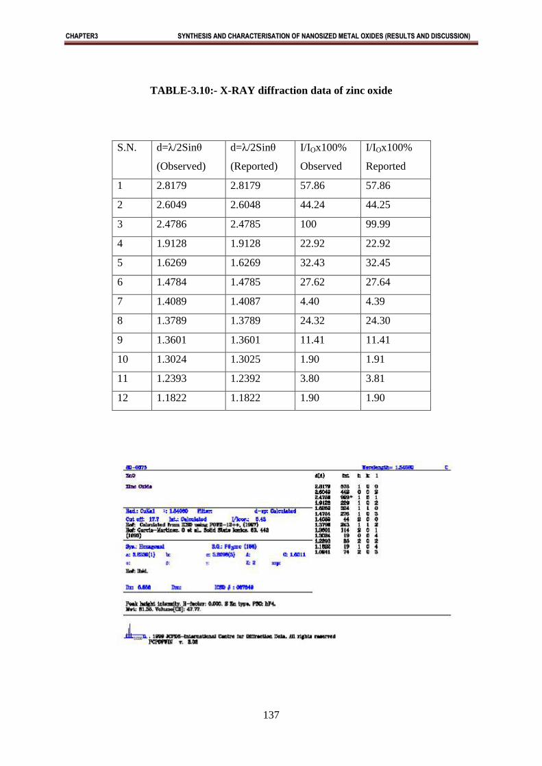
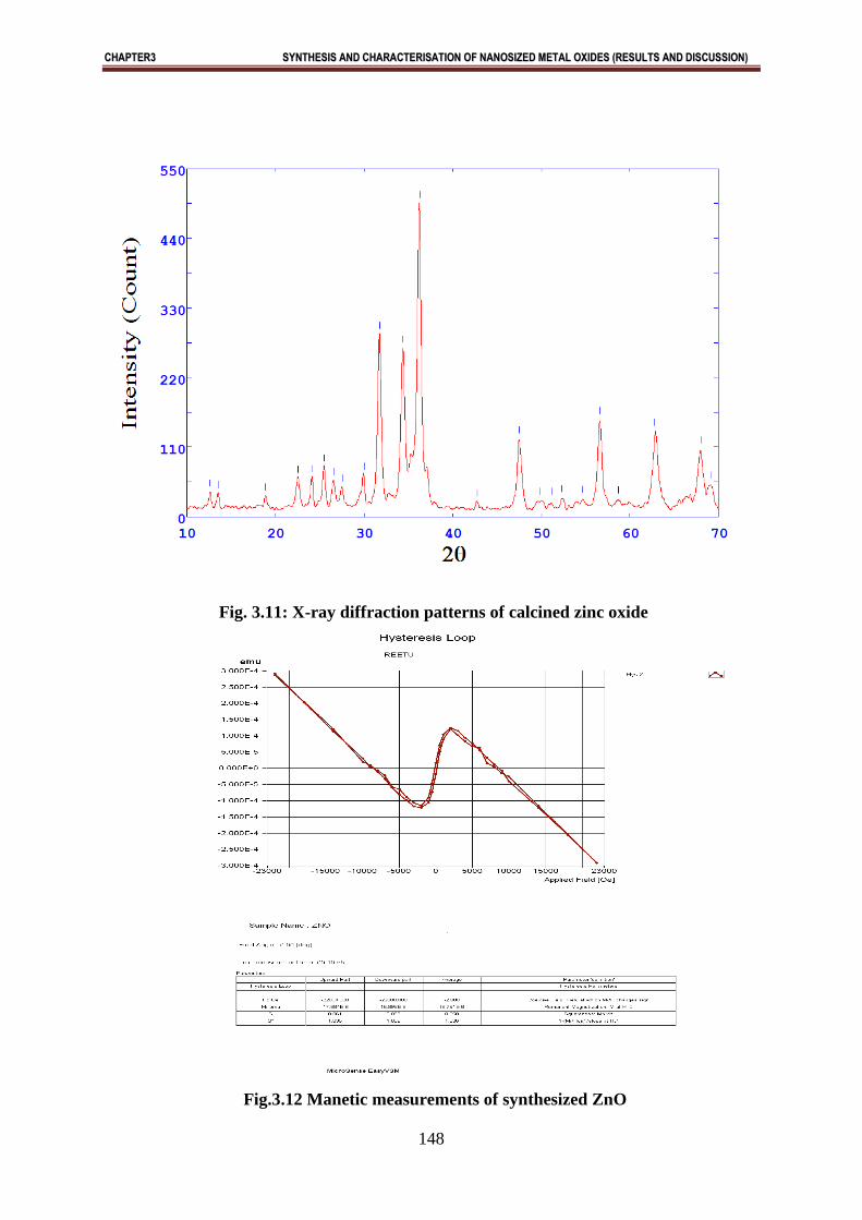
surface characteristics. X-Ray diffraction of synthesized zinc oxide is shown in Fig. (3.11).
X-ray diffraction patter of pure zinc-oxide indicated that zinc oxide in the form of ZnO
having hexagonal wutrzite structure Fig. (3.11). In X-ray diffraction, some prominent peaks
were considered and corresponding d-values (2.8179, 2.6049, 2.4786……..) were compared
with standards JCPDS file No 80-0075 (Table No. 3.10). X-ray diffraction shows that metal
oxide is pure ZnO having ZnO is a single crystalline and exhibit hexagonal structure. X-ray
diffraction shows high degree of orientation. It is found that form is anisotropic that on
average crystallites may be regarded as cylinders but they are in fact right prisms whose cross
section is an irregular hexagon. Size of the crystals was also calculated using Scherrer
equation and it was observed that it support TEM studies. X-ray diffraction data indicates that
CCHHAAPPTTEERR33 SSYYNNTTHHEESSIISS AANNDD CCHHAARRAACCTTEERRIISSAATTIIOONN OOFF NNAANNOOSSIIZZEEDD MMEETTAALL OOXXIIDDEESS ((RREESSUULLTTSS AANNDD DDIISSCCUUSSSSIIOONN))
126
ZnO naoparticles have hexagonal unit cell structure. Individual nanoparticles having size 21-
40 nm were found.
Magnetic Measurements:
The zinc oxide is amphoteric oxide and semiconductor at room temperature.It has excellent
piezoelectric properties. It is possible to induce room temperature ferromagnetic like behavior
in ZnO nanoparticles without doping with magnetic impurities but simply inducing an
ferromagnetic alteration of their electronic configuration.(Fig.3.12)
Thermal Analysis:
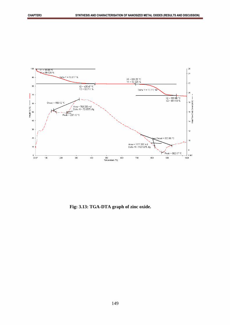
Thermal analysis includes a group of techniques in which a physical property of a substance
is measured as a function of temperature or time while the substance is subjected to a
controlled temperature programme. The analysis involves thermogravity (TG), differential
thermal analysis (DTA) and derivative Thermogravimetry (DTG). Thermal Gravimetric
studies of the calcined oxides prepared were done between a temperature range of 10-10000C
under N2 atmosphere. The TGA/DTA curves of the oxides are shown in Fig. (3.13). The
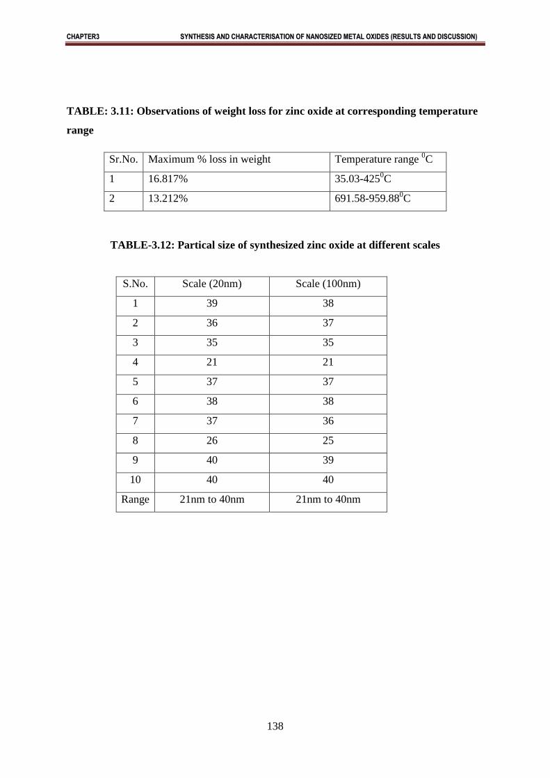
maximum total weight loss observed for zinc oxide and their corresponding temperature is
summarized in Table (3.11). Results showed that in the synthesized oxides shows some
weight loss and oxide undergoing decomposition, dehydration or any physical change. From
TGA curve we observed that zinc oxides shows stable weight loss above 959.880C. In DTA
curve also, there is exothermic and endothermic peak which shows phase transition, solid
state reach on any chemical reaction occurred during heating treatment. From TGA curve we
observed that zinc oxide showed stable weight loss above 959.880C [Fig.3.13].
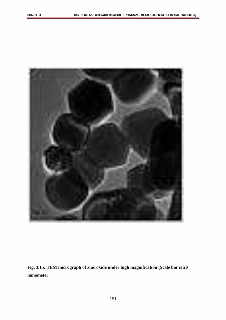
SEM and TEM Studies :
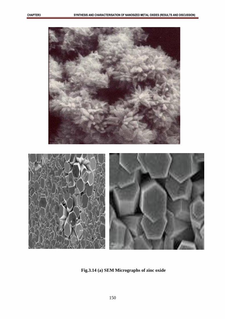
Morphology of the sample was investigated using SEM and TEM. Parts of Fig.3.14 shows
typical SEM images of the sample. Scanning electron microscopy shows the hexagonal
structure of zinc oxide Fig. (3.14). SEM images demonstrate that a bulk quantity of flower
like bunches exist. Fig.5 shows TEM images of the sample. The flower like nanostructure is
observed. During the TEM sample preparation, flower like nanostructures were not destroyed
. This indicates that the formation of flower like nanostructures is not due to aggregation.
TEM is evidence for formation of hexagonal ZnO nanoparticles. TEM studies shows that
the ZnO nanoparticle are hexagonal and size of the obtained nanoparticles is in the range 21-
40 nm. [Table 3.12]
CCHHAAPPTTEERR33 SSYYNNTTHHEESSIISS AANNDD CCHHAARRAACCTTEERRIISSAATTIIOONN OOFF NNAANNOOSSIIZZEEDD MMEETTAALL OOXXIIDDEESS ((RREESSUULLTTSS AANNDD DDIISSCCUUSSSSIIOONN))
127
Abstract:
In conclusion, a general and facile approach has been developed to prepare nanosized zinc
oxide from commercially available reagents by aqueous precipitation method. There is great
attention in zinc oxide nanoparticles both from the point of view of simpler , cheaper and
easy handling using aqueous precipitation method and determination of fundamental
properties. The results indicates that nanosized zinc oxide nanopricles with hexagonal
wurtzite crystal structure. From TEM studies it is found that particle has average size of 21-
40 nm. SEM studies indicate that ZnO has hexagonal structure. Magnetic measurements
showed that ferromagnetic nature.This method is advantageous over the existing methods for
synthesis of nanosized zinc oxide. Therfore the proposed method is very much promising and
have extensive applications.
CCHHAAPPTTEERR33 SSYYNNTTHHEESSIISS AANNDD CCHHAARRAACCTTEERRIISSAATTIIOONN OOFF NNAANNOOSSIIZZEEDD MMEETTAALL OOXXIIDDEESS ((RREESSUULLTTSS AANNDD DDIISSCCUUSSSSIIOONN))
128
3.4 A simple and effective method of the synthesis of NiO nanoparticles
Transition metal oxides have many applications as catalyst [88], sensors [89-92],
superconductors [93-94] and adsorbents [95-96]. NiO has a variety of specialized
applications and generally applications distinguish between "chemical", which is relatively
pure material for specialty applications, and "metallurgical grade", which is mainly used for
the production of alloys. It is used in the ceramic industry to make frits, ferrites, and
porcelain glazes. The sintered oxide is used to produce nickel steel alloys. NiO was also a
component in the nickel-iron battery, also known as the Edison Battery, and is a component
in fuel cells. It is the precursor to many nickel salts, for use as specialty chemicals and
catalysts. More recently, NiO was used to make the NiCd rechargeable batteries found in
many electronic devices until the development of the environmentally superior lithium ion
battery [97]. Nickel oxide has many catalytic applications as nickel – uranium oxide catalyst
has been used for the hydrogenation of carbon dioxide to methane [98].
Potassium/calcium/nickel oxides has been observed as a good catalyst for the oxidative
coupling of methane [99]. Mixed nickel–manganese oxides with an ilmenite and spinel
structure have been investigated in order to elucidate the effect of the crystal structure type
and cation coordination on the catalytic performance in the reactions of complete oxidation
of ethyl acetate, benzene and carbon monoxide. Nickel–manganese oxides with an ilmenite-
type structure are perspective catalysts for catalytic neutralization of exhaust gases from
organic compounds [100-103]. Nickel–manganese mixed oxides NiMn2O4 spinel was used
for the partial conversion of methane [104-105]. As nickel oxide has wide applications in
industry and catalyst for reactions, an attempt has been made to synthesize nickel oxide
nanoparticles by simple aqueous precipitation using ammonia as precipitating agent. This
method involves a simple, cheap and one step process for synthesis of NiO nanaoparticles.
The obtained particles of NiO have size from 28-50nm. The synthesized nanoparticles were
characterized by XRD, TGA, magnetic susceptibility, SEM and TEM.
3.4.1 Results and discussions
X-ray studies
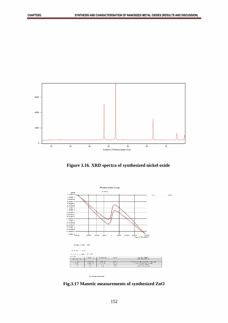
X-ray diffraction of synthesized nickel oxide is shown in Fig. 3.16. X-ray diffraction pattern
of pure nickel oxide indicated that nickel oxide in the form of NiO having rhombhohedral
structure. In X-ray diffraction, some prominent peaks were considered and corresponding d-
values were compared with the standard [JCPDS file No. 89-7350] (Table-3.13). X-ray
diffraction showed that metal oxide is pure NiO having rhombhohedral structure. Size of the
CCHHAAPPTTEERR33 SSYYNNTTHHEESSIISS AANNDD CCHHAARRAACCTTEERRIISSAATTIIOONN OOFF NNAANNOOSSIIZZEEDD MMEETTAALL OOXXIIDDEESS ((RREESSUULLTTSS AANNDD DDIISSCCUUSSSSIIOONN))
129
crystals was also calculated using Scherrer equation and it was observed that it supports
TEM studies.
Magnetic measurements
The magnetic moment for nickel oxide is found to be 2.691 B.M. This value of magnetic
moment supported the fact that the formed nickel oxide is in the form of NiO with actual
magnetic moment 2.828 B.M. This indicated that 2 unpaired electron being present in NiO.
Thus the oxide formed is paramagnetic in nature (Table3.16).
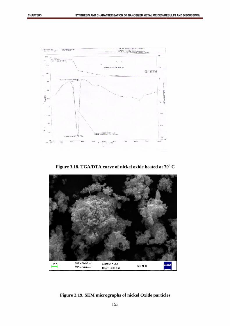
TGA/ DTA studies
From TGA curve we observed that nickel oxides showed stable weight loss above 600ºC
[Fig.3.18]. It simply indicates that the temperature required for formation of nickel oxide
was 600ºC (Table3.15).
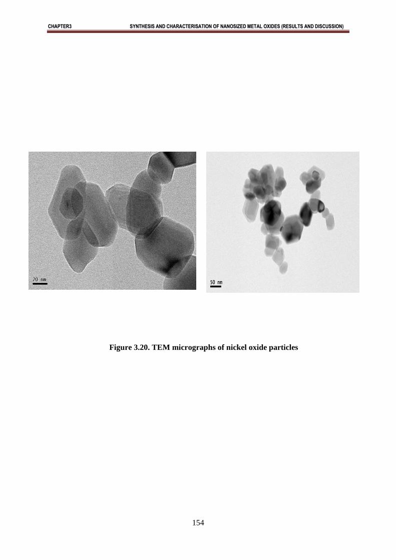
SEM and TEM studies
SEM and TEM studies were performed to find out the morphology and exact particle size of
synthesized NiO. TEM showed that the NiO nanoparticles having particle size in the range
of 28 – 50 nm are in good agreement of nanosized particles (Fig.3.19 and Fig. 3.20).
Abstract:
NiO nanoparticles with rhombhohedral structure were synthesized successfully by aqueous
precipitation method. From TEM study, it is found that particles have average size of 28-50
nm. Magnetic measurements showed that NiO has two unpaired electrons and hence
paramagnetic in nature. This method is advantageous over the existing methods for
synthesis of nanoparticles because other methods required specialized instrumentation,
highly skilled labour, expensive materials and methods. Therefore, the proposed
precipitation method is very much promising and may have extensive applications.
CCHHAAPPTTEERR33 SSYYNNTTHHEESSIISS AANNDD CCHHAARRAACCTTEERRIISSAATTIIOONN OOFF NNAANNOOSSIIZZEEDD MMEETTAALL OOXXIIDDEESS ((RREESSUULLTTSS AANNDD DDIISSCCUUSSSSIIOONN))
130
Table 3.1: X-ray diffraction data for iron oxide (αααα - Fe2O3)
S. No. d ( A0)
(Observed)
d ( A0)
(Reported)
I/I0 × 100 %
(Observed)
I/I0 × 100 %
(Reported)
1. 3.6806 3.6775 35.78 58.7
2. 2.6980 2.6959 100.00 100
3. 2.5155 2.5135 83.14 63.1
4. 2.2033 2.2015 24.03 3.4
5. 1.8394 1.8379 36.98 6.1
6. 1.6949 1.6936 43.26 18.0
7. 1.4852 1.4840 26.88 18.1
8. 1.4511 1.4512 26.77 9.7
CCHHAAPPTTEERR33 SSYYNNTTHHEESSIISS AANNDD CCHHAARRAACCTTEERRIISSAATTIIOONN OOFF NNAANNOOSSIIZZEEDD MMEETTAALL OOXXIIDDEESS ((RREESSUULLTTSS AANNDD DDIISSCCUUSSSSIIOONN))
131
TABLE 3. 2: Observations on magnetic susceptibilities of synthesized iron oxide
Experimental Conditions:
Applied Magnetic field= 5.0 Kilo gauss
Temperature = 296K
S. N. Name of Oxide R=µ1-µ2
(e.m.u)
W=w1-w2
(gm)
µcalculated = µ1-µ µobserved (B.M.)
1 Iron Oxide 0.741x10-
2
0.01654 5.82 5.92
µcalculated = √n(n+2) and µobserved = 2.84√RTM/HW
Where
n= no. of unpaired electron.
R = Magnetic Moment in B.M.
T = absolute Temperature.
M= Molecular weight
H= Applied Magnetic Field
W = Weight of Sample.
TABLE: 3.3: Observations of weight loss for iron oxide at corresponding temperature
range
Sr.No. Maximum % loss in weight Temperature range
1 27.3% 23-500
2 0.9% 500-994
CCHHAAPPTTEERR33 SSYYNNTTHHEESSIISS AANNDD CCHHAARRAACCTTEERRIISSAATTIIOONN OOFF NNAANNOOSSIIZZEEDD MMEETTAALL OOXXIIDDEESS ((RREESSUULLTTSS AANNDD DDIISSCCUUSSSSIIOONN))
132
TABLE -3. 4: Partical size of synthesized iron oxide at different scales
S.No. Scale 50nm Scale 100nm
1 15 17
2 40 34
3 20 25
4 22 26
5 34 49
6 44 35
7 25 28
8 49 49
9 15 29
10 39 21
Range 15nm to 49nm 15 nm to 49nm
CCHHAAPPTTEERR33 SSYYNNTTHHEESSIISS AANNDD CCHHAARRAACCTTEERRIISSAATTIIOONN OOFF NNAANNOOSSIIZZEEDD MMEETTAALL OOXXIIDDEESS ((RREESSUULLTTSS AANNDD DDIISSCCUUSSSSIIOONN))
133
Table-3.5 Magnetic susceptibility data of iron oxide
Temperature(K)
Volt(mV)
Magnetic moment(e.m.u.)
300
5.75
0.0050
290
5.58
0.0051
280
5.38
0.0052
270
5.17
0.0054
260
4.96
0.0055
250
4.75
0.0057
240
4.54
0.0060
230
4.33
0.0062
220
4.13
0.0056
200
3.71
0.0049
180
3.29
0.0045
160
2.88
0.0043
140
2.46
0.0042
120
2.05
0.0041
100
1.63
0.0040
CCHHAAPPTTEERR33 SSYYNNTTHHEESSIISS AANNDD CCHHAARRAACCTTEERRIISSAATTIIOONN OOFF NNAANNOOSSIIZZEEDD MMEETTAALL OOXXIIDDEESS ((RREESSUULLTTSS AANNDD DDIISSCCUUSSSSIIOONN))
134
Table-3.6 X-RAY diffraction data for copper oxide
S. No. d=λ / 2sinθ
(Observed)
d=λ / 2sinθ
(Reported)
I/I 0X100%
(Observed)
I/I 0X100%
(Reported)
1. 2.52028 2.519 100 100
2. 2.31782 2.314 80.46 70
3. 1.86566 1.851 17.24 15
4. 1.50415 1.492 12.76 11
5. 1.40758 1.320 11.27 10
6. 1.37337 1.311 10.43 8
CCHHAAPPTTEERR33 SSYYNNTTHHEESSIISS AANNDD CCHHAARRAACCTTEERRIISSAATTIIOONN OOFF NNAANNOOSSIIZZEEDD MMEETTAALL OOXXIIDDEESS ((RREESSUULLTTSS AANNDD DDIISSCCUUSSSSIIOONN))
135
TABLE 3. 7: Observations on magnetic susceptibilities of synthesized coppper oxide
Experimental Conditions:
Applied Magnetic field= 5.0 Kilo gauss
Temperature = 296K
Sr
.N
o
Name of Oxide R=µ1-µ2 (e.m.u) W=w1-w2
(gm)
µcalculated
= µ1-µ
µobserved (B.M.)
1 Iron Oxide 0.741x10⁻² 0.01654 5.82 5.92
µcalculated = √n(n+2) and µobserved = 2.84√RTM/HW
Where
n= no. of unpaired electron.
R = Magnetic Moment in B.M.
T = absolute Temperature.
M= Molecular weight
H= Applied Magnetic Field
W = Weight of Sample.
TABLE: 3.8: Observations of weight loss for copper oxide at corresponding
temperature range
Sr.No. Maximum % loss in weight Temperature range
1 27.3% 23-500
2 0.9% 500-994
CCHHAAPPTTEERR33 SSYYNNTTHHEESSIISS AANNDD CCHHAARRAACCTTEERRIISSAATTIIOONN OOFF NNAANNOOSSIIZZEEDD MMEETTAALL OOXXIIDDEESS ((RREESSUULLTTSS AANNDD DDIISSCCUUSSSSIIOONN))
136
TABLE -3. 9: Particle size of synthesized copper oxide at different scales
S.No. Scale 50nm Scale 100nm
1 12 15
2 16 18
3 19 20
4 35 35
5 12 14
6 35 35
7 22 24
8 34 28
9 18 30
10 29 34
Range 12 nm to 35 nm 12 nm to 35 nm
CCHHAAPPTTEERR33 SSYYNNTTHHEESSIISS AANNDD CCHHAARRAACCTTEERRIISSAATTIIOONN OOFF NNAANNOOSSIIZZEEDD MMEETTAALL OOXXIIDDEESS ((RREESSUULLTTSS AANNDD DDIISSCCUUSSSSIIOONN))
137
TABLE-3.10:- X-RAY diffraction data of zinc oxide
S.N. d=λ/2Sinθ
(Observed)
d=λ/2Sinθ
(Reported)
I/IOx100%
Observed
I/IOx100%
Reported
1 2.8179 2.8179 57.86 57.86
2 2.6049 2.6048 44.24 44.25
3 2.4786 2.4785 100 99.99
4 1.9128 1.9128 22.92 22.92
5 1.6269 1.6269 32.43 32.45
6 1.4784 1.4785 27.62 27.64
7 1.4089 1.4087 4.40 4.39
8 1.3789 1.3789 24.32 24.30
9 1.3601 1.3601 11.41 11.41
10 1.3024 1.3025 1.90 1.91
11 1.2393 1.2392 3.80 3.81
12 1.1822 1.1822 1.90 1.90
CCHHAAPPTTEERR33 SSYYNNTTHHEESSIISS AANNDD CCHHAARRAACCTTEERRIISSAATTIIOONN OOFF NNAANNOOSSIIZZEEDD MMEETTAALL OOXXIIDDEESS ((RREESSUULLTTSS AANNDD DDIISSCCUUSSSSIIOONN))
138
TABLE: 3.11: Observations of weight loss for zinc oxide at corresponding temperature
range
TABLE-3.12: Partical size of synthesized zinc oxide at different scales
S.No. Scale (20nm) Scale (100nm)
1 39 38
2 36 37
3 35 35
4 21 21
5 37 37
6 38 38
7 37 36
8 26 25
9 40 39
10 40 40
Range 21nm to 40nm 21nm to 40nm
Sr.No. Maximum % loss in weight Temperature range 0C
1 16.817% 35.03-4250C
2 13.212% 691.58-959.880C
CCHHAAPPTTEERR33 SSYYNNTTHHEESSIISS AANNDD CCHHAARRAACCTTEERRIISSAATTIIOONN OOFF NNAANNOOSSIIZZEEDD MMEETTAALL OOXXIIDDEESS ((RREESSUULLTTSS AANNDD DDIISSCCUUSSSSIIOONN))
139
Table 3.13 X-RAY diffraction data for NiO
S. No. d=λ / 2sinθ
(Observed)
d=λ / 2sinθ
(Reported)
I/I 0x100%
(Observed)
I/I 0x100%
(Reported)
1. 2.39 2.41 56 57
2. 2.07 2.08 100 100
3. 1.47 1.47 38 27
4. 1.25 1.25 13 10
5. 1.20 1.20 8 8
CCHHAAPPTTEERR33 SSYYNNTTHHEESSIISS AANNDD CCHHAARRAACCTTEERRIISSAATTIIOONN OOFF NNAANNOOSSIIZZEEDD MMEETTAALL OOXXIIDDEESS ((RREESSUULLTTSS AANNDD DDIISSCCUUSSSSIIOONN))
140
-2
-1.5
-1
-0.5
0
0.5
1
1.5
2
-4000 -2000 0 2000 4000
Fig.3.1- XRD spectra of synthesized iron oxide
Fig.3.2. (a) Morin transition curve for synthesized iron oxide nanoparticles.
(b) VSM studies of synthesized iron oxide.
100 150 200 250 300
0.8
0.9
1.0
1.1
1.2
1.3
Ferromagnetic
χχχχ vs T graph for α α α α - Fe2O
3
enter text here
Antiferromagnetic
230 Κ230 Κ230 Κ230 Κ
χχ χχ
T
Position [°2Theta] (Copper (Cu)) 20 30 40 50 60 70 80 90
0
200
400
600
800
(b)
(a)
CCHHAAPPTTEERR33 SSYYNNTTHHEESSIISS AANNDD CCHHAARRAACCTTEERRIISSAATTIIOONN OOFF NNAANNOOSSIIZZEEDD MMEETTAALL OOXXIIDDEESS ((RREESSUULLTTSS AANNDD DDIISSCCUUSSSSIIOONN))
141
Fig.3.3. TGA/DTA curve of iron oxide heated at 70o C
CCHHAAPPTTEERR33 SSYYNNTTHHEESSIISS AANNDD CCHHAARRAACCTTEERRIISSAATTIIOONN OOFF NNAANNOOSSIIZZEEDD MMEETTAALL OOXXIIDDEESS ((RREESSUULLTTSS AANNDD DDIISSCCUUSSSSIIOONN))
142
Figure 3.4 : SEM images of iron oxide partic
CCHHAAPPTTEERR33 SSYYNNTTHHEESSIISS AANNDD CCHHAARRAACCTTEERRIISSAATTIIOONN OOFF NNAANNOOSSIIZZEEDD MMEETTAALL OOXXIIDDEESS ((RREESSUULLTTSS AANNDD DDIISSCCUUSSSSIIOONN))
143
(a) (b)
CCHHAAPPTTEERR33 SSYYNNTTHHEESSIISS AANNDD CCHHAARRAACCTTEERRIISSAATTIIOONN OOFF NNAANNOOSSIIZZEEDD MMEETTAALL OOXXIIDDEESS ((RREESSUULLTTSS AANNDD DDIISSCCUUSSSSIIOONN))
144
Figure 3.5: TEM images of iron oxide particles
(c) (d)
CCHHAAPPTTEERR33 SSYYNNTTHH
Figure 3.7: VSM images of copper oxide particles
Fig.3.6- XRD spectra of synthesized copper oxide
10 200
1000
2000
HHEESSIISS AANNDD CCHHAARRAACCTTEERRIISSAATTIIOONN OOFF NNAANNOOSSIIZZEEDD MMEETTAALL OOXXIIDDEESS ((RREE
145
Figure 3.7: VSM images of copper oxide particles
XRD spectra of synthesized copper oxide
Position [°2Theta] (Copper (Cu)) 20 30 40 50 60
EESSUULLTTSS AANNDD DDIISSCCUUSSSSIIOONN))
70
CCHHAAPPTTEERR33 SSYYNNTTHHEESSIISS AANNDD CCHHAARRAACCTTEERRIISSAATTIIOONN OOFF NNAANNOOSSIIZZEEDD MMEETTAALL OOXXIIDDEESS ((RREESSUULLTTSS AANNDD DDIISSCCUUSSSSIIOONN))
146
Figure 3.8: TGA-DTA images of copper oxide particles
Figure 3.9: SEM images of copper oxide particles
CCHHAAPPTTEERR33 SSYYNNTTHHEESSIISS AANNDD CCHHAARRAACCTTEERRIISSAATTIIOONN OOFF NNAANNOOSSIIZZEEDD MMEETTAALL OOXXIIDDEESS ((RREESSUULLTTSS AANNDD DDIISSCCUUSSSSIIOONN))
147
Figure 3.10: TEM images of copper oxide particles
CCHHAAPPTTEERR33 SSYYNNTTHHEESSIISS AANNDD CCHHAARRAACCTTEERRIISSAATTIIOONN OOFF NNAANNOOSSIIZZEEDD MMEETTAALL OOXXIIDDEESS ((RREESSUULLTTSS AANNDD DDIISSCCUUSSSSIIOONN))
148
Fig. 3.11: X-ray diffraction patterns of calcined zinc oxide
Fig.3.12 Manetic measurements of synthesized ZnO
CCHHAAPPTTEERR33 SSYYNNTTHHEESSIISS AANNDD CCHHAARRAACCTTEERRIISSAATTIIOONN OOFF NNAANNOOSSIIZZEEDD MMEETTAALL OOXXIIDDEESS ((RREESSUULLTTSS AANNDD DDIISSCCUUSSSSIIOONN))
149
Fig: 3.13: TGA-DTA graph of zinc oxide.
CCHHAAPPTTEERR33 SSYYNNTTHHEESSIISS AANNDD CCHHAARRAACCTTEERRIISSAATTIIOONN OOFF NNAANNOOSSIIZZEEDD MMEETTAALL OOXXIIDDEESS ((RREESSUULLTTSS AANNDD DDIISSCCUUSSSSIIOONN))
150
Fig.3.14 (a) SEM Micrographs of zinc oxide
CCHHAAPPTTEERR33 SSYYNNTTHHEESSIISS AANNDD CCHHAARRAACCTTEERRIISSAATTIIOONN OOFF NNAANNOOSSIIZZEEDD MMEETTAALL OOXXIIDDEESS ((RREESSUULLTTSS AANNDD DDIISSCCUUSSSSIIOONN))
151
Fig. 3.15: TEM micrograph of zinc oxide under high magnification (Scale bar is 20
nanometer
CCHHAAPPTTEERR33 SSYYNNTTHHEESSIISS AANNDD CCHHAARRAACCTTEERRIISSAATTIIOONN OOFF NNAANNOOSSIIZZEEDD MMEETTAALL OOXXIIDDEESS ((RREESSUULLTTSS AANNDD DDIISSCCUUSSSSIIOONN))
152
Figure 3.16. XRD spectra of synthesized nickel oxide
Fig.3.17 Manetic measurements of synthesized ZnO
Position [°2Theta] (Copper (Cu))
10 20 30 40 50 60 70
0
2000
4000
6000
CCHHAAPPTTEERR33 SSYYNNTTHH
Figure 3.18. TGA/DTA curve of nickel oxide heated at 70
Figure 3.19. SEM
HHEESSIISS AANNDD CCHHAARRAACCTTEERRIISSAATTIIOONN OOFF NNAANNOOSSIIZZEEDD MMEETTAALL OOXXIIDDEESS ((RREE
153
. TGA/DTA curve of nickel oxide heated at 70
Figure 3.19. SEM micrographs of nickel Oxide particles
EESSUULLTTSS AANNDD DDIISSCCUUSSSSIIOONN))
. TGA/DTA curve of nickel oxide heated at 70o C
particles
CCHHAAPPTTEERR33 SSYYNNTTHHEESSIISS AANNDD CCHHAARRAACCTTEERRIISSAATTIIOONN OOFF NNAANNOOSSIIZZEEDD MMEETTAALL OOXXIIDDEESS ((RREESSUULLTTSS AANNDD DDIISSCCUUSSSSIIOONN))
154
Figure 3.20. TEM micrographs of nickel oxide particles
CCHHAAPPTTEERR33 SSYYNNTTHHEESSIISS AANNDD CCHHAARRAACCTTEERRIISSAATTIIOONN OOFF NNAANNOOSSIIZZEEDD MMEETTAALL OOXXIIDDEESS ((RREESSUULLTTSS AANNDD DDIISSCCUUSSSSIIOONN))
155
References:
1. J. Z. Xu, J. J., Zhu, H. Wang and H. Y.Chen, Anal. Lett. 36 ( 2003) 2723-2733.
2. W.zhong, B. Liu, Zhong-kuan, Ren, Xiang-zhong and Zhang, Jr. of Alloys and
Compounds., 465 ( 2008) 261-264.
3. L. H.Chun, J.L. Lu, C.L. Chu, C.Y. Lai, G. Wu, 2nd international conference 2008 2nd
IEEE International Nanoelectronics Conference, 485-488.
4. T. G. Altincekic, I. Boz, S. J. Aktürk , Nanoscience Nanotechnology. 8 (2008)874-877.
5. S.Bennici,V. Gervasini, A. Ragaini , Ultrasonic sonochemistry, 10, 2(2003) 61-64.
6. M.Yang, J. Hu, X.Yan, C.Cheng, Z.Zhao, Y.Zuo, Surface and interface Physics papers A,
155, 2(2011) 692-698.
7. H.Wei, H. Sun, S. Wang, G. Chen, Y. Hou, H. Guo, X. Ma, Jr. of Natural Gas Chemistry,1
(2010) 393-396.
8. A.Guimin, Z. Yang, L.Zhimin, Zhenhang, H.Buxing, M. Shidding, L.Jianping, Nanotechnology,
19 ( 2008) 101-103.
9. S.S.Sharma.,K.Nomura, Y.U.Jihira, , Journal of Material Science, 26 (1999) 4104-4109.
10. V.Pillai, P. Kumar, M.J. Hou, P. Ayyub, D.O. Shah, Advance in colloid and Interface
Science, 55 (1995)241-269.
11. W. Rongcheng, Q. Jiuhui, H. Hong, Y. Yunbo , Journal of Beijing University of chemical
technology (Natural science edition), 48 (2003) 2311-2316.
12. W. R. Zou, Z. Han, J. S. Zhang, L.Hangmin, Jr. of Chemical and Engineering data, 51 (
2006) 534-541.
CCHHAAPPTTEERR33 SSYYNNTTHHEESSIISS AANNDD CCHHAARRAACCTTEERRIISSAATTIIOONN OOFF NNAANNOOSSIIZZEEDD MMEETTAALL OOXXIIDDEESS ((RREESSUULLTTSS AANNDD DDIISSCCUUSSSSIIOONN))
156
13. H. Runping, H.Lina, Z. Xin, X. Yanfang, X. Feng, L. Yinli, Y.Wang, Jr. of Chemical
Engineering, 149 (2009) 123-131.
14. P.Baldrin,V. Merhautova, J. Gabriel, F.Nerud, P.Stopka, M.Hruby, M.J. Benes, Applied
Catalysis B-Environmental, 66 ( 2006) 258-264.
15. N.S.Chaubal, M.R. Sawant, catalysis communications, 7 (2006)443 - 449.
16. L.Sanchez, J.A. David, Applied Catalysis A, 291 (2005) 230 - 237.
17. T. Zaki, Journal of Colloid and Interface Science, 284 (2005) 606 - 613.
18. E.Rombi, I.Ferino, R.C. Picciau, V. Solinas, R.Buzzoni, , Applied Catalysis A, 266 (2004)
73 - 79.
19. R.Andreozzi, C.Vincenzo, M.Raffaele , Water Research, 37 (2003) 3682 - 3688.
20. S.H.Taylor, G. Hutchings, J.M. Palacios,L. Lee, Catalysis Today, 81 (2003) 171 - 178.
21. B.Sreedhar, V. Bhaskar, T. Sridhar, L. Srinivas, K. S.Klára, Journal of Molecular Catalysis
A: Chemical ,191( 2003) 141 – 147.
22. G. Ketteler, W.Ranke, R.Schlogl, Journal of Catalysis, 212 ( 2002)104 – 111.
23. J.Bandara, A. Mielczarski, A. Lopez, I.Kiwi, Applied Catalysis B: Environmental 12 (2001)
321- 333,
24. S. Sugiyama, K. Kastuma, N. Fukuda, T.Shono, T. Moriga, H. Hayashi, Catalysis
Communications, 2 ( 2001) 285 – 290.
25. H.Grabowska, R. Klimkiewicz, J. Wrzyszcz, L.Syper, Journal of Molecular Catalysis A:
Chemical 154 (2000)225 - 228.
CCHHAAPPTTEERR33 SSYYNNTTHHEESSIISS AANNDD CCHHAARRAACCTTEERRIISSAATTIIOONN OOFF NNAANNOOSSIIZZEEDD MMEETTAALL OOXXIIDDEESS ((RREESSUULLTTSS AANNDD DDIISSCCUUSSSSIIOONN))
157
26. V.Duma, D. Honicke, Journal of Catalysis, 191( 2000)93-104.
27. V.Dumaa, K. Poppa, M.C.Kung, H.Zhoub,S.Nguyenb, S. Ohyamac, H.H. Kung, C.L.
Marshall, Chemical Engineering Journal, 99 (2004) 227 - 236.
28. C.T.Wang, R.J.Willey, Catalysis Today, 52 ( 1999) 83 - 89.
29. S.Chou, H. Chihpin, Chemosphere, 38 (1999) 2719.
30. Y.Wang, B.H. Davis, Applied Catalysis A, 180 (1999) 277 -288.
31. M.Lauwiner, R. Roth, P. Rys, Applied Catalysis A, 177 (1999)9 -14.
32. M.Benz, M. V. Kraan, A.M. Prins, Applied Catalysis A: General 172 (1998) 149 - 155.
33. P.Baldrian, M. Vera, J. Gabriel, F.Nerud, P. Stopka, H. Martin ,M.J. Benes, M. Applied
Catalysis B: Environmental, 66 (2006) 258 - 264.
34. N.S.Chaubal, M.R. Sawant, Catalysis Communications, 7 (2006)443 - 449.
35. S.L.Miller, L.E.Orgel, Englewood Clifts, N.J., P.83 (1974)129- 134
36. P. Horowitz, J. Berger and A.Katchalsky, Nature, 228 (1970) 636 – 639.
37. J.Wang, J., Zhu, Z.Munir, .Talanta, 84 (2011) 783-788.
38. J.Chomoucka, J. Drbohlavova, D.,Huska, V. Adam, R. Kizek, R. Hubalek, Pharmacological
Research, , 62 (2010) 144-149.
39. C.S.Kumar, F.Mohammad, Advanced Drug Delivery Reviews, 63 (2011) 789-808.
40. J.Z.Xu J.J. Zhu, H. Wang and H.Y.Chen, Anal. Lett. 36 (2003) 2723-2733.
W.zhong B. Liu, , Z.kuan, R. X.zhong Jr. of Alloys and Compounds. 465 (2008)261-264.
CCHHAAPPTTEERR33 SSYYNNTTHHEESSIISS AANNDD CCHHAARRAACCTTEERRIISSAATTIIOONN OOFF NNAANNOOSSIIZZEEDD MMEETTAALL OOXXIIDDEESS ((RREESSUULLTTSS AANNDD DDIISSCCUUSSSSIIOONN))
158
41. H.C. Lu; J.L. Lu; C.L. Chu; C.Y. Lai; G. Wu, 2nd international conference 2008 2nd
IEEE International Nanoelectronics Conference, 485-488.
42. T.G.Altinçekiç I.Boz , S. Aktürk , Nanosci Nanotechnol., 8 ( 2008)874-877.
43. B.Simona , A. Gervasini and V. Ragaini , Ultrasonic sonochemistry, 10 (2003)61-64.
44. M.Yang, J.He,H. Xiaochun, C. Yan, Z.Cheng,and Y. Zhao, Nanosci Nanotechnol., 8( 2008)874-877.
45. H. Zuo, Surface and interface Physics papers A 155( 2011)692-698.
46. H. Wei, H. Sun, S. Wang, G. Chen, Y.Hou, H. Guo1,
X. Ma1,Jr. of Natural Gas Chemistry,1 (2010) 393-396.
47. A.Guimin, Z.Yang, L.Zhimin, M.Zhenhang., H. Buxing., M. Shidding and L. Jianping,
Nanotechnology, 19 (2008)101-103
48. Sharma., S.S. Nomura, K. and Jihira,Journal of Material Science, 26
(1999) 4104-4109.
49. V.Pillai, P. Kumar, M.J. Hou, P. Ayyub, D.O. Shah, Advance in colloid and Interface
Science, 55 (1995) 241-269.
50. W.Rongcheng, J.Qu, H.He and Y. Yu, Journal of Beijing University of chemical technology
(Natural science edition), 48 (2003) 2311-2316.
51. W.R.Zou, Z. Han, J. Zhang, J. Shi and Hangmin, Jr. of Chemical and Engineering data, 51 (
2006)534-541.
52. H.Runping, H. Lina, Z. Xin, Z. Yanfang, X. Feng, X. Yinli, L. and Y.Wang,
Jr. of Chemical Engineering, 149 (2009), 123-131.
53. S.Lee, U.S. Choi, S. Li, J.A. Eastman, J. Heat Transfer, 121(1999), 280.
54. A.Rakhshni, Preparation, Solid State Electron., 29(1986) 7 -17.
55. R.V.Kumar,Y. Diamant, Y. Gedanken, Chem. Mater. 12(2000) 2301-2305.
56. K.Borgohain,K. Singh, J.B. Rama Rao, M.V., Shripathi, T. Mahamuni, S. Phys. Rev., 61
(2000), 11093.
57. J.Xu, J.F. Ji, W. Shen, Z.X. . Tang, S.H. Ye, X.R. Jia, D.Z. Xin, X.Q., Solid State Chem., 147
( 2000) 516.
CCHHAAPPTTEERR33 SSYYNNTTHHEESSIISS AANNDD CCHHAARRAACCTTEERRIISSAATTIIOONN OOFF NNAANNOOSSIIZZEEDD MMEETTAALL OOXXIIDDEESS ((RREESSUULLTTSS AANNDD DDIISSCCUUSSSSIIOONN))
159
58. K.Nakao, S. Ikeyama, M. Mizota, T. Jin, P. Tazawa, M. Miyagawa, Y. Miyagawa, S. Wang,
S. Wang, Rep. Res. Cent. Ion Beam Technol., 18( 2000 ) 153.
59. A. Punnoose, A. Magnone, H. and S. M. S. Bonevich , Phys. Rev. B 64, 64 (2001)174-
420.
60. W.zhong , B. Liu, Z.K. Luo, X.Z. Ren and P.X. Zhang, Jr. of Alloys and Compounds,1-
2(2008),261-264.
61. L.Yu , REU Research Accomplishments,1( 2008)46 – 47.
62. J.Z. Xu, J.J.Zhu, H. Wang & H.Y. Chen , Analytical Letters Volume 36, Issue 13(2003)2723-
2733.
63. W.zhong , B. Liu, Z.K. Luo, X.Z. Ren, P.X.Zhang, sonochemical methods, 465, 1–2(2008)
261–264.
64. H.S.Lu,J.Lu,C.L.Chu,C.Y.Lai,G.W.Wu,research.cgu.edu.tw/ezfiles/14/1014/img/651/97-B-
32.pdf
65. H.M Xiong ,D.G.Shchukin , H.Mohwald, Y.Xu andY.Y.Xia, Angewandte Chemie
International Edition, 15 (2009) 2727-2731
66. D.C.Look , Mater.Sci.Eng.B 80 (2001) 383
67. C.M. Lieber , Solid State Communication ,66 (1998) 5309
68. Y.Zhang , K.Suenaga, C. Collies, S.Iijima , Science 281 (1998) 973
69. L.Vayssieres, K.Kies ,A.Hagfeldt, S.E.Lindquist, Chem. Mater, 13 (2001) 4395
70. Z.W.Pan , Z.R.Dai, Z.L.Wang, Science 292 (2001) 1947
71. W.C.Schin, M.S. Wu, J.Cryst. Growth 137 (1994) 319
72. C.X.Xu, X.W.Sun , Appl. Phys. Lett. 83 (2003) 3806
73. R.Paneva, D.Gotchev,Sens.Actuat.A :Phys.72 (1999) 79
74. L.Gao,Q.Li, W.L.Luan, J.Am. Ceram.Soc. 85 (2002) 1016
75. N.F.Cooray, K.Kushiya, A.Fujimaki, D.Okumura,M.Sato, M.Ooshita, O.Yamase,Jpn.J.Appl.
Phys. 38 (1999) 6213
CCHHAAPPTTEERR33 SSYYNNTTHHEESSIISS AANNDD CCHHAARRAACCTTEERRIISSAATTIIOONN OOFF NNAANNOOSSIIZZEEDD MMEETTAALL OOXXIIDDEESS ((RREESSUULLTTSS AANNDD DDIISSCCUUSSSSIIOONN))
160
76. P.X.Gao, Y.Ding ,W.Mai, W.L.Huges, C.S.Lao, Z.L.Wang, Science 309 (2005) 1700
77. E.Topoglidis, A.E.G.Cass, B.Oregan, J.R.Durrant, J.Electoanal. Chem. 517 (2001) 20
78. N.T.Hung, N.D.Quang, S.Bernick, J.Mater. Res. 16 (2001) 2817
79. J.A.Rodriguez, T.Jirsak, J.Dvorak,S.Sambasivan, D.J.Fisher, J.Phys. Chem. B 104 (2000)
319
80. A.B.Moghaddam, T.Nazari,J.Badraghi and M.Kazemzad ,Int.J. Electochem. Sci. , 4 (2009)
247-257
81. R.Rajendran, C.Balakumar, H.A.M. Ahammed , S.Jayakumar, K.Vaideki and E.M.Rajesh,
Int. J. of Engineering Science and Technology , 1 (2010) 202-208
82. Z.L. Wang and J.Song ,”Piezoelectric naogenerators based on zinc oxide nanowire arrays,”
Science ,312 (2006) 242-246
83. X.Wang ,J.Song,J.Liu and L.W.Zhong, “Direct-Current nanogenerator driven by ultrasonic
waves,” Science , 316 (2007) 102-105
84. C.Chang, V.H.Tran ,J.Wang, Y.K.Fuh and L.Lin ,”Direct write piezoelectric polymeric
nanogenerator with high energy conversion efficiency,” Nanoletters , 2 (2010) 726-731
85. S.Xu, Y.Quin, C.Xu,Y.Wei,R.Yang and Z.L. Wang ,”Self powered nanowire devices” Nature
Nanotechnology,5, 5 (2010) 366-373
86. H.M.Huang,S.Mao, H.Fecik, H.Yan, Y.Wu,H.Kind,E.Weber,R.Russo, P.D.Yang, Science
292 (2001) 1897
87. J. Xu , J.Zhu, J. Wang and H.Chen, Anal. Lett. 36,13(2003): 2723-2733.
88. W.Lv, L.Bo, L.Zhong , X.zhong and Z. P.Xin ,Jr. of Alloys and Compounds. 465(2008) 261-
264.
89. H.C. Lu, J.L. Lu, C.L. Chu, C.Y. Lai, G. Wu, 2nd international conference, 2nd IEEE
International Nanoelectronics Conference :1 (2008) 485-488.
90. C.Altinçeki, Boz , S.Aktürk , Nanosci Nanotechnol, 8 (2008): 874-877.
91. B.Simona , G.Antonella and R.Vittorio, Ultrasonic sonochemistry 10(2003) 61-64.
CCHHAAPPTTEERR33 SSYYNNTTHHEESSIISS AANNDD CCHHAARRAACCTTEERRIISSAATTIIOONN OOFF NNAANNOOSSIIZZEEDD MMEETTAALL OOXXIIDDEESS ((RREESSUULLTTSS AANNDD DDIISSCCUUSSSSIIOONN))
161
92. Y.Mingqing , H.Junhui ,H. Xiaochun , Y.Chunxiao , Z. Cheng, Y.Zhao and G. Surface and
interface Physics papers A 155 (2011), 692-698.
93. W.Hongbing , S.Hongwen ,W. Sumei, C. G. Chen, Y. Hou, H. Guo, X. Ma , Jr. of Natural
Gas Chemistry, 3 (2010), 393-396.
94. A. Guimin, Z. Yang, L.Zhimin, M.Zhenhang., H. Buxing., M. Shidding and L. Jianping
Nanotechnology, 19 (2008) 101-103.
95. S.Sharma., S.S. Nomura, K. and Jihira ,Journal of Material Science, 26 (1999), 4104-4109.
96. V.Pillai, V. Kumar, P. Hou, M.J. Ayyub, P. Shah, Advance in colloid and Interface Science,
55 (1995) 241-269.
97. R. Wu, J. Qu, H. and Y. Journal of Beijing University of chemical technology (Natural
science edition), 48 (2003)2311-2316.
98. A.Zou, W R. Han, Z.Zhang, J. Shi and Hangmin, Jr. of Chemical and Engineering data, 51
(2006) 534-541.
99. H.Runping, H. Lina, Z. Xin, Z. Yanfang, X. Feng, X. Yinli, L. Wang,Jr. of Chemical
Engineering, 149 (2009)123-131.
100. Handbook of Inorganic Chemicals", Pradniak, Pradyot; McGraw-Hill Publications, 2002.
101. J.Frank and A. Murray,Applied Catalysis A: General, 100 (1993) 131-143.
102. K. M. Dooley, J.R.H. Ross, Applied Catalysis A: General, 90 (1992) 159-174.
103. R.M. María ,P. Bibiana, P. Barbero and L E. Cadús ,Applied Catalysis B:
Environmental,1–2 (2007) 1-10
104. R.C.Comptes R. C., Maha H.,S. Ouaguenouni, B. A. Kiennemann,A. Barama, ,Applied
Catalysis B: Environmental,12 (2009) 740-747

CCHHAAPPTTEERR33 SSYYNNTTHHEESSIISS AANNDD CCHHAARRAACCTTEERRIISSAATTIIOONN OOFF NNAANNOOSSIIZZEEDD MMEETTAALL OOXXIIDDEESS ((RREESSUULLTTSS AANNDD DDIISSCCUUSSSSIIOONN))
162
Recommended