Recommended Practice for Drill Stem Design and Operating Limits
API RECOMMENDED PRACTICE 7GSIXTEENTH EDITION, AUGUST 1998
EFFECTIVE DATE: DECEMBER 1998ERRATA: MAY 2000
Addendum 1November 2003Addendum Effective Date: May 1, 2004

Addendum 1 to Recommended Practice for Drill Stem Design and Operating Limits
1
Page 3, 4.5:
Change “A.8” to “A.9”
Page 5, Table 2, Footnote :
Change “A.15” to “A.16”
Page 12, Table 8 and Page 14, Table 9, Note 4:
Change “
5
/
8
inch” to “
3
/
4
inch” in Note 4
For Pages 15 – 17, most corrections for Table 10 are in Column 7. Additional corrections in Table 10:
Page 15:
2
3
/
8
in, 4.85 lb/ft, E75 drill pipe with 2
3
/
8
OHLW connections the makeup torque for premium class (Column 10) should be “1,723”2
3
/
8
in, 4.85 lb/ft, E75 drill pipe with 2
3
/
8
OHLW connections the makeup torque for Class 2 (Column 13) should be “1,481”2
3
/
8
in, 6.65 lb/ft, E75 drill pipe with 2
3
/
8
OHSW connections the makeup torque for premium class (Column 10) should be “2,216”2
3
/
8
in, 6.65 lb/ft, E75 drill pipe with 2
3
/
8
OHSW connections the makeup torque for Class 2 (Column 13) should be “1,967”2
7
/
8
in, 6.85 lb/ft, E75 drill pipe with 2
7
/
8
OHLW connections the makeup torque for premium class (Column 10) should be “3,290”2
7
/
8
in, 6.85 lb/ft, E75 drill pipe with 2
7
/
8
OHLW connections the makeup torque for Class 2 (Column 13) should be “2,804”2
7
/
8
in, 10.40 lb/ft, E75 drill pipe with 2
7
/
8
OHSW connections the makeup torque for premium class (Column 10) should be “4,411”2
7
/
8
in, 10.40 lb/ft, E75 drill pipe with 2
7
/
8
OHSW connections the makeup torque for Class 2 (Column 13) should be “4,079”2
7
/
8
in, 10.40 lb/ft, E75 drill pipe with 2
7
/
8
PAC connections the makeup torque for premium class (Column 10) should be “3,424”2
7
/
8
in, 10.40 lb/ft, E75 drill pipe with 2
7
/
8
PAC connections the makeup torque for Class 2 (Column 13) should be “3,424”
Page 16:
4
1
/
2
IEU-X95, NC46, Column 6, change “3
1
/
4
” to “3”
Page 17:
Last line, Column 11, minimum OD for 6
5
/
8
in, 27.70 lb/ft S135 drill pipe, Class 2, change “7
27
/
64
” to “7
27
/
32
”
2 API R
ECOMMENDED
P
RACTICE
7G—A
DDENDUM
1
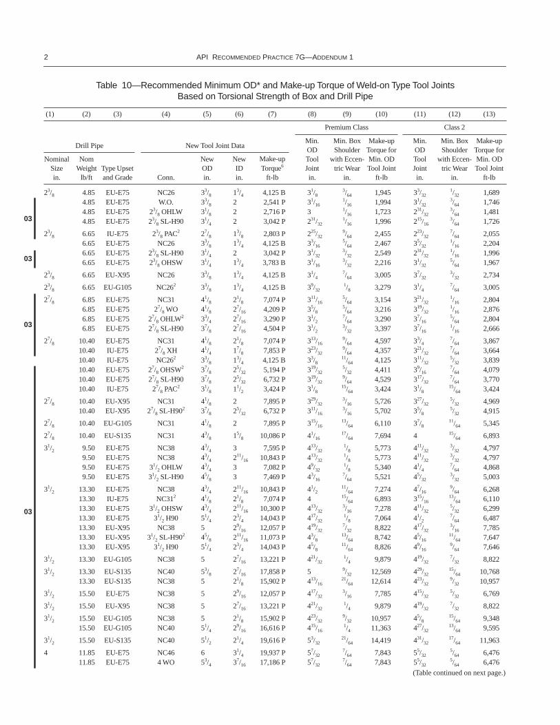
Table 10—Recommended Minimum OD* and Make-up Torque of Weld-on Type Tool Joints Based on Torsional Strength of Box and Drill Pipe
(1) (2) (3) (4) (5) (6) (7) (8) (9) (10) (11) (12) (13)
Drill Pipe New Tool Joint Data
Premium Class Class 2
Min.ODToolJointin.
Min. Box Shoulder
with Eccen-tric Wear
in.
Make-up Torque for Min. OD Tool Joint
ft-lb
Min.ODToolJointin.
Min. Box Shoulder
with Eccen-tric Wear
in.
Make-up Torque for Min. OD Tool Joint
ft-lb
NominalSizein.
Nom Weight
lb/ftType Upset and Grade Conn.
NewODin.
NewIDin.
Make-up Torque
6
ft-lb
2
3
/
8
4.85 EU-E75 NC26 3
3
/
8
1
3
/
4
4,125 B 3
1
/
83
/
64
1,945 3
3
/
321
/
32
1,6894.85 EU-E75 W.O. 3
3
/
8
2 2,541 P 3
1
/
161
/
16
1,994 3
1
/
323
/
64
1,7464.85 EU-E75 2
3
/
8
OHLW 3
1
/
8
2 2,716 P 3
1
/
16
1,723 2
31
/
323
/
64
1,4814.85 EU-E75 2
3
/
8
SL-H90 3
1
/
4
2 3,042 P 2
31
/
321
/
16
1,996 2
15
/
163
/
64
1,726
2
3
/
8
6.65 IU-E75 2
3
/
8
PAC
2
2
7
/
8
1
3
/
8
2,803 P 2
25
/
329
/
64
2,455 2
23
/
327
/
64
2,0556.65 EU-E75 NC26 3
3
/
8
1
3
/
4
4,125 B 3
3
/
165
/
64
2,467 3
5
/
321
/
16
2,2046.65 EU-E75 2
3
/
8
SL-H90 3
1
/
4
2 3,042 P 3
1
/
323
/
32
2,549 2
31
/
321
/
16
1,9966.65 EU-E75 2
3
/
8
OHSW 3
1
/
4
1
3
/
4
3,783 B 3
1
/
163
/
32
2,216 3
1
/
325
/
64
1,967
2
3
/
8
6.65 EU-X95 NC26 33/8 13/4 4,125 B 31/47/64 3,005 37/32
3/32 2,734
23/8 6.65 EU-G105 NC262 33/8 13/4 4,125 B 39/321/8 3,279 31/4
7/64 3,005
27/8 6.85 EU-E75 NC31 41/8 21/8 7,074 P 311/165/64 3,154 321/32
1/16 2,8046.85 EU-E75 27/8 WO 41/8 27/16 4,209 P 35/8
5/64 3,216 319/321/16 2,876
6.85 EU-E75 27/8 OHLW2 33/4 27/16 3,290 P 31/27/64 3,290 37/16
5/64 2,8046.85 EU-E75 27/8 SL-H90 37/8 27/16 4,504 P 31/2
3/32 3,397 37/161/16 2,666
27/8 10.40 EU-E75 NC31 41/8 21/8 7,074 P 313/169/64 4,597 33/4
7/64 3,86710.40 IU-E75 27/8 XH 41/4 17/8 7,853 P 323/32
9/64 4,357 321/327/64 3,664
10.40 IU-E75 NC262 33/8 13/4 4,125 B 33/811/64 4,125 311/32
5/32 3,83910.40 EU-E75 27/8 OHSW2 37/8 25/32 5,194 P 319/32
5/32 4,411 39/167/64 4,079
10.40 EU-E75 27/8 SL-H90 37/8 25/32 6,732 P 319/329/64 4,529 317/32
7/64 3,77010.40 IU-E75 27/8 PAC2 31/8 11/2 3,424 P 31/8
15/64 3,424 31/815/64 3,424
27/8 10.40 EU-X95 NC31 41/8 2 7,895 P 329/323/16 5,726 327/32
5/32 4,96910.40 EU-X95 27/8 SL-H902 37/8 25/32 6,732 P 311/16
3/16 5,702 35/85/32 4,915
27/8 10.40 EU-G105 NC31 41/8 2 7,895 P 315/1613/64 6,110 37/8
11/64 5,345
27/8 10.40 EU-S135 NC31 43/8 15/8 10,086 P 41/1617/64 7,694 4 15/64 6,893
31/2 9.50 EU-E75 NC38 43/4 3 7,595 P 413/321/8 5,773 411/32
3/32 4,7979.50 EU-E75 NC38 43/4 211/16 10,843 P 413/32
1/8 5,773 411/323/32 4,797
9.50 EU-E75 31/2 OHLW 43/4 3 7,082 P 49/321/8 5,340 41/4
7/64 4,8689.50 EU-E75 31/2 SL-H90 45/8 3 7,469 P 43/16
7/64 5,521 45/323/32 5,003
31/2 13.30 EU-E75 NC38 43/4 211/16 10,843 P 41/211/64 7,274 47/16
9/64 6,26813.30 IU-E75 NC312 41/8 21/8 7,074 P 4 15/64 6,893 315/16
13/64 6,11013.30 EU-E75 31/2 OHSW 43/4 211/16 10,300 P 413/32
3/16 7,278 411/325/32 6,299
13.30 EU-E75 31/2 H90 51/4 23/4 14,043 P 417/321/8 7,064 41/2
7/64 6,48713.30 EU-X95 NC38 5 29/16 12,057 P 419/32
7/32 8,822 417/323/16 7,785
13.30 EU-X95 31/2 SL-H902 45/8 211/16 11,073 P 43/813/64 8,742 45/16
11/64 7,64713.30 EU-X95 31/2 H90 51/4 23/4 14,043 P 45/8
11/64 8,826 49/169/64 7,646
31/2 13.30 EU-G105 NC38 5 27/16 13,221 P 421/321/4 9,879 419/32
7/32 8,822
31/2 13.30 EU-S135 NC40 53/8 27/16 17,858 P 5 9/32 12,569 429/3215/64 10,768
13.30 EU-S135 NC38 5 21/8 15,902 P 413/1621/64 12,614 423/32
9/32 10,957
31/2 15.50 EU-E75 NC38 5 29/16 12,057 P 417/323/16 7,785 415/32
5/32 6,769
31/2 15.50 EU-X95 NC38 5 27/16 13,221 P 421/321/4 9,879 419/32
7/32 8,822
31/2 15.50 EU-G105 NC38 5 21/8 15,902 P 423/329/32 10,957 45/8
15/64 9,34815.50 EU-G105 NC40 51/4 29/16 16,616 P 415/16
1/4 11,363 427/3213/64 9,595
31/2 15.50 EU-S135 NC40 51/2 21/4 19,616 P 53/3221/64 14,419 431/32
17/64 11,963
4 11.85 EU-E75 NC46 6 31/4 19,937 P 57/327/64 7,843 55/32
5/64 6,47611.85 EU-E75 4 WO 53/4 37/16 17,186 P 57/32
7/64 7,843 55/325/64 6,476
03
03
03
03
(Table continued on next page.)
RECOMMENDED PRACTICE FOR DRILL STEM DESIGN AND OPERATING LIMITS 3
11.85 EU-E75 4 OHLW 51/4 315/32 13,186 P 5 9/64 7,866 415/167/64 6,593
11.85 IU-E75 4 H90 51/2 213/16 21,185 P 47/87/64 7,630 427/32
3/32 6,962
4 14.00 IU-E75 NC40 51/4 213/16 13,968 P 413/163/16 9,017 43/4
5/32 7,87714.00 EU-E75 NC46 6 31/4 19,937 P 59/32
9/64 9,233 57/327/64 7,843
14.00 IU-E75 4 SH2 45/8 29/16 9,016 P 47/1615/64 8,782 43/8
13/64 7,81714.00 EU-E75 4 OHSW 51/2 31/4 16,236 P 51/16
11/64 9,131 5 9/64 7,83914.00 IU-E75 4 H90 51/2 213/16 21,185 P 415/16
9/64 8,986 47/87/64 7,630
4 14.00 IU-X95 NC40 51/4 211/16 15,319 P 415/161/4 11,363 427/32
13/64 9,59514.00 EU-X95 NC46 6 31/4 19,937 P 53/8
3/16 11,363 55/165/32 9,937
14.00 IU-X95 4 H90 51/2 213/16 21,185 P 51/323/16 11,065 431/32
5/32 9,673
4 14.00 IU-G105 NC40 51/2 27/16 17,858 P 5 9/32 12,569 429/3215/64 10,768
14.00 EU-G105 NC46 6 31/4 19,937 P 57/167/32 12,813 511/32
11/64 10,64714.00 IU-G105 4 H90 51/2 213/16 21,185 P 53/32
7/32 12,481 51/323/16 11,065
4 14.00 EU-S135 NC46 6 3 23,399 P 59/169/32 15,787 51/2
1/4 14,288
4 15.70 IU-E75 NC40 51/4 211/16 15,319 P 47/87/32 10,179 425/32
11/64 8,44415.70 EU-E75 NC46 6 31/4 19,937 P 55/16
5/32 9,937 51/41/8 8,535
15.70 IU-E75 4 H90 51/2 213/16 21,185 P 431/325/32 9,673 429/32
1/8 8,305
4 15.70 IU-X95 NC40 51/2 27/16 17,858 P 5 9/32 12,569 429/3215/64 10,768
15.70 EU-X95 NC46 6 3 23,399 P 57/167/32 12,813 511/32
11/64 10,64715.70 IU-X95 4 H90 51/2 213/16 21,185 P 53/32
7/32 12,481 51/323/16 11,065
4 15.70 EU-G105 NC46 6 3 23,399 P 515/3215/64 13,547 513/32
13/64 12,08515.70 IU-G105 4 H90 51/2 213/16 21,185 P 55/32
1/4 13,922 51/1613/64 11,770
4 15.70 IU-S135 NC46 6 25/8 26,982 B 521/3221/64 18,083 517/32
17/64 15,03515.70 EU-S135 NC46 6 27/8 25,038 P 521/32
21/64 18,083 517/3217/64 15,035
41/2 16.60 IEU-E75 41/2 FH 6 3 20,620 P 53/813/64 12,125 59/32
5/32 10,07216.60 IEU-E75 NC46 61/4 31/4 19,937 P 513/32
13/64 12,085 511/3211/64 10,647
16.60 IEU-E75 41/2 OHSW 57/8 33/4 16,162 P 57/1613/64 11,862 53/8
11/64 10,37516.60 EU-E75 NC50 65/8 33/4 22,361 P 523/32
5/32 11,590 511/169/64 10,773
16.60 IEU-E75 41/2 H-90 6 31/4 23,126 P 511/323/16 12,215 59/32
5/32 10,642
41/2 16.60 IEU-X95 41/2 FH 6 23/4 23,695 P 51/217/64 14,945 513/32
7/32 12,82116.60 IEU-X95 NC46 61/4 3 19,937 P 517/32
17/64 15,035 57/167/32 12,813
16.60 EU-X95 NC50 65/8 33/4 22,361 P 527/327/32 14,926 525/32
3/16 13,24516.60 IEU-X95 41/2 H-90 6 3 26,969 P 515/32
1/4 15,441 53/813/64 13,013
41/2 16.60 IEU-G105 41/2 FH 6 23/4 23,695 P 59/1619/64 16,391 515/32
1/4 14,23116.60 IEU-G105 NC46 61/4 3 23,399 P 519/32
19/64 16,546 51/21/4 14,288
16.60 EU-G105 NC50 65/8 33/4 22,361 P 529/321/4 16,633 513/16
13/64 14,08216.60 IEU-G105 41/2 H-90 6 3 26,969 P 51/2
17/64 16,264 57/1615/64 14,625
41/2 16.60 IEU-S135 NC46 61/4 23/4 26,615 P 525/3225/64 21,230 521/32
21/64 18,08316.60 EU-S135 NC50 65/8 31/2 26,674 P 61/16
21/64 21,017 531/329/32 18,367
41/2 20.00 IEU-E75 41/2 FH 6 3 20,620 P 515/321/4 14,231 53/8
13/64 12,12520.00 IEU-E75 NC46 61/4 3 23,399 P 51/2
1/4 14,288 513/3213/64 12,085
20.00 EU-E75 NC50 65/8 35/8 24,549 P 513/1613/64 14,082 53/4
12/64 12,41520.00 IEU-E75 41/2 H-90 6 3 26,969 P 513/32
7/32 13,815 511/323/16 12,215
41/2 20.00 IEU-X95 41/2 FH 6 21/2 26,528 P 55/821/64 17,861 517/32
9/32 15,66520.00 IEU-X95 NC46 61/4 23/4 26,615 P 521/32
21/64 18,083 59/169/32 15,787
20.00 EU-X95 NC50 65/8 31/2 26,674 P 515/1617/64 17,497 57/8
15/64 15,77620.00 IEU-X95 41/2 H-90 6 3 26,969 P 59/16
19/64 17,929 515/321/4 15,441
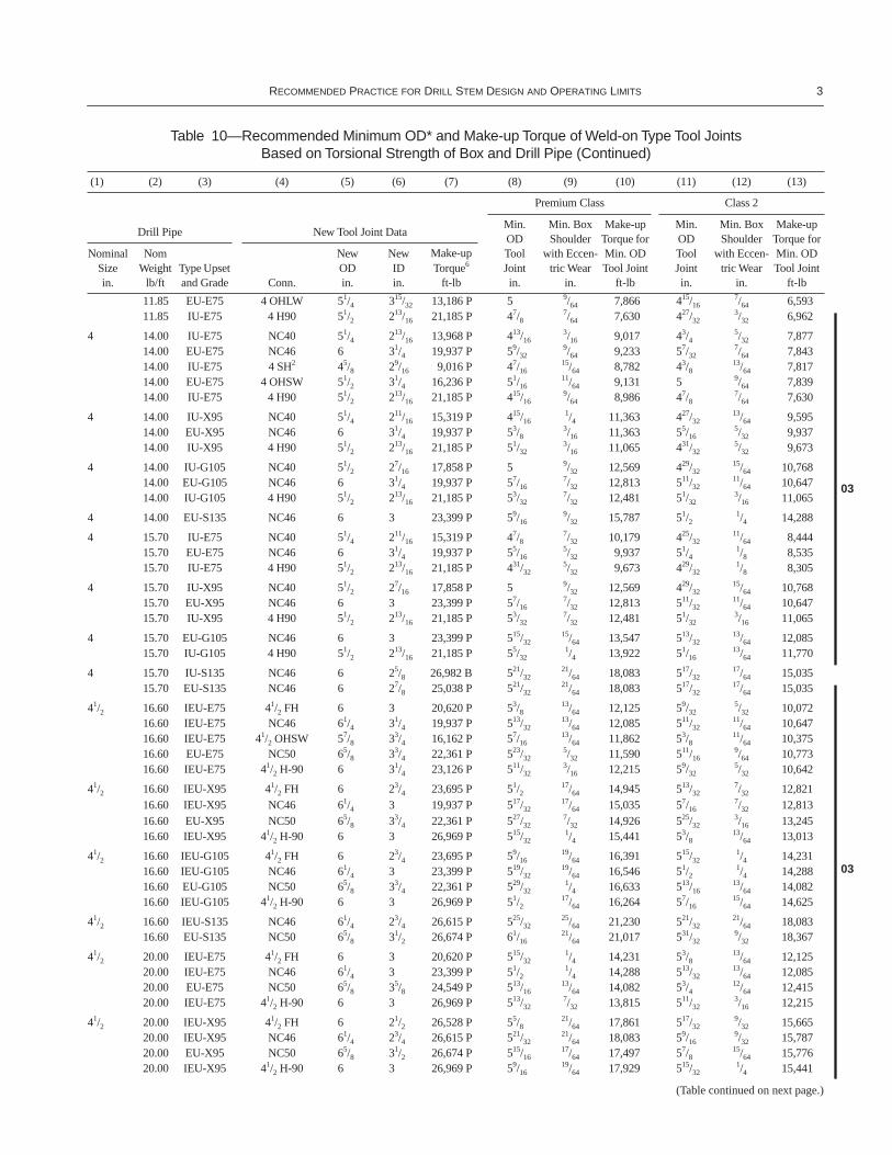
Table 10—Recommended Minimum OD* and Make-up Torque of Weld-on Type Tool Joints Based on Torsional Strength of Box and Drill Pipe (Continued)
(1) (2) (3) (4) (5) (6) (7) (8) (9) (10) (11) (12) (13)
Drill Pipe New Tool Joint Data
Premium Class Class 2
Min.ODToolJointin.
Min. Box Shoulder
with Eccen-tric Wear
in.
Make-up Torque for Min. OD Tool Joint
ft-lb
Min.ODToolJointin.
Min. Box Shoulder
with Eccen-tric Wear
in.
Make-up Torque for Min. OD Tool Joint
ft-lb
NominalSizein.
Nom Weight
lb/ftType Upset and Grade Conn.
NewODin.
NewIDin.
Make-up Torque6
ft-lb
03
03
(Table continued on next page.)
4 API RECOMMENDED PRACTICE 7G—ADDENDUM 1
41/2 20.00 IEU-G105 NC46 61/4 21/2 29,578 P 523/3223/64 19,644 55/8
5/16 17,31120.00 EU-G105 NC50 65/8 31/2 26,674 P 61/32
5/16 20,127 529/321/4 16,633
41/2 20.00 EU-S135 NC50 65/8 3 34,520 P 67/3213/32 25,569 63/32
11/32 21,914
5 19.50 IEU-E75 NC50 65/8 33/4 22,361 P 57/815/64 15,776 513/16
13/64 14,082
5 19.50 IEU-X95 NC50 65/8 31/2 26,674 P 61/325/16 20,127 515/16
17/64 17,49719.50 IEU-X95 5 H-90 61/2 31/4 30,732 P 527/32
19/64 19,862 53/41/4 17,116
5 19.50 IEU-G105 NC50 65/8 31/4 30,730 P 63/3211/32 21,914 6 19/64 19,244
19.50 IEU-G105 5 H-90 61/2 3 34,805 P 529/3221/64 21,727 513/16
9/32 18,940
5 19.50 IEU-S135 NC50 65/8 23/4 38,036 P 65/1629/64 28,381 63/16
25/64 24,64519.50 IEU-S135 51/2 FH 71/4 31/2 43,328 P 63/4
3/8 28,737 65/85/16 24,412
5 25.60 IEU-E75 NC50 65/8 31/2 26,674 P 61/325/16 20,127 515/16
17/64 17,49725.60 IEU-E75 51/2 FH 7 31/2 37,742 B 61/2
1/4 20,205 613/3213/64 17,127
5 25.60 IEU-X95 NC50 65/8 3 34,520 P 67/3213/32 25,569 63/32
11/32 21,91425.60 IEU-X95 51/2 FH 7 31/2 37,742 B 621/32
21/64 25,483 69/169/32 22,294
5 25.60 IEU-G105 NC50 65/8 23/4 38,036 P 69/327/16 27,437 65/32
3/8 23,72825.60 IEU-G105 51/2 FH 71/4 31/2 43,328 P 623/32
23/64 27,645 65/85/16 24,412
5 25.60 IEU-S135 51/2 FH 71/4 31/4 47,230 B 615/1615/32 35,446 613/16
13/32 30,943
51/2 21.90 IEU-E75 51/2 FH 7 4 33,412 P 615/3215/64 19,172 613/32
13/64 17,127
51/2 21.90 IEU-X95 51/2 FH 7 33/4 37,742 B 65/85/16 24,412 617/32
17/64 21,24621.90 IEU-X95 51/2 H-90 7 31/2 34,820 P 63/16
21/64 24,414 63/329/32 21,349
51/2 21.90 IEU-G105 51/2 FH 71/4 31/2 43,328 P 623/3223/64 27,645 619/32
19/64 23,350
51/2 21.90 IEU-S135 51/2 FH 71/2 3 52,059 P 615/1615/32 35,446 613/16
13/32 30,943
51/2 24.70 IEU-E75 51/2 FH 7 4 33,412 P 69/169/32 22,294 615/32
15/64 19,172
51/2 24.70 IEU-X95 51/2 FH 71/4 31/2 43,328 P 623/3223/64 27,645 619/32
19/64 23,350
51/2 24.70 IEU-G105 51/2 FH 71/4 31/2 43,328 P 625/3225/64 29,836 611/16
11/32 26,560
51/2 24.70 IEU-S135 51/2 FH 71/2 3 52,059 P 71/3233/64 38,901 67/8
7/16 33,180
65/8 25.20 IEU-E75 65/8 FH 8 5 43,934 P 77/161/4 26,810 73/8
7/32 24,100IEU-X95 65/8 FH 8 5 43,934 P 75/8
11/32 35,139 71/29/32 29,552
IEU-G105 65/8 FH 81/4 43/4 51,280 P 711/165/8 37,983 719/32
21/64 33,730IEU-S135 65/8 FH 81/2 41/4 65,012 P 729/32
31/64 48,204 725/3227/64 42,312
65/8 27.70 IEU-E75 65/8 FH 8 5 43,934 P 71/29/32 29,552 713/32
15/64 25,451IEU-X95 65/8 FH 81/4 43/4 51,280 P 711/16
3/8 37,983 79/165/16 32,329
IEU-G105 65/8 FH 81/4 43/4 51,280 P 73/413/32 40,860 721/32
23/64 36,556IEU-S135 65/8 FH 81/2 41/4 65,012 P 8 17/32 52,714 727/32
29/64 45,241
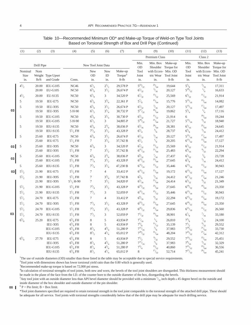
1The use of outside diameters (OD) smaller than those listed in the table may be acceptable due to special service requirements. 2Tool joint with dimensions shown has lower torsional yield ratio than the 0.80 which is generally used.3Recommended make-up torque is based on 72,000 psi stress.4In calculation of torsional strengths of tool joints, both new and worn, the bevels of the tool joint shoulders are disregarded. This thickness measurement should be made in the plane of the face from the I.D. of the counter bore to the outside diameter of the box, disregarding the bevels.5Any tool joint with an outside diameter less than API bevel diameter should be provided with a minimum 1/32 inch depth x 45 degree bevel on the outside and inside diameter of the box shoulder and outside diameter of the pin shoulder.6 P = Pin limit; B = Box limit.*Tool joint diameters specified are required to retain torsional strength in the tool joint comparable to the torsional strength of the attached drill pipe. These should be adequate for all service. Tool joints with torsional strengths considerably below that of the drill pipe may be adequate for much drilling service.
Table 10—Recommended Minimum OD* and Make-up Torque of Weld-on Type Tool Joints Based on Torsional Strength of Box and Drill Pipe (Continued)
(1) (2) (3) (4) (5) (6) (7) (8) (9) (10) (11) (12) (13)
Drill Pipe New Tool Joint Data
Premium Class Class 2
Min.ODToolJointin.
Min. Box Shoulder
with Eccen-tric Wear
in.
Make-up Torque for Min. OD Tool Joint
ft-lb
Min.ODToolJointin.
Min. Box Shoulder
with Eccen-tric Wear
in.
Make-up Torque for Min. OD Tool Joint
ft-lb
NominalSizein.
Nom Weight
lb/ftType Upset and Grade Conn.
NewODin.
NewIDin.
Make-up Torque6
ft-lb
03
03
03
03
03
00
RECOMMENDED PRACTICE FOR DRILL STEM DESIGN AND OPERATING LIMITS 5
Page 38, Table 14, Footnote 1:Change “A.8” to “A.9”
Page 112, replace 13.1 with the following:
13.1 DRILL STRING MARKING AND IDENTIFICATION
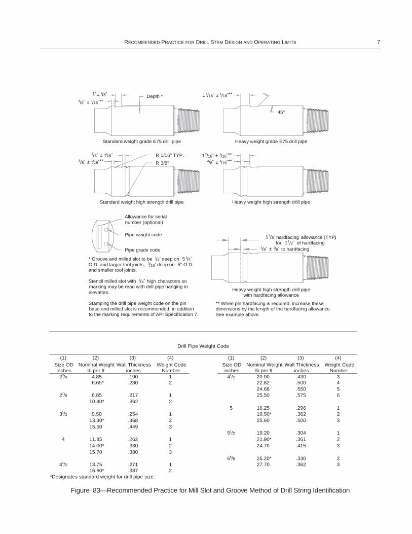
Sections of drill string manufactured in accordance with API Specification 7 are identified with markings on the base of the pinconnection. An additional pin base marking, representing the drill pipe weight code, is recommended as shown in Figure 82. Therecommended weight codes are shown in Figure 83. It is recommended that drill string members not covered by API Specification7 also be stenciled at the base of the pin as shown in Figure 82. It is also recommended that drill string members be marked usingthe mill slot and groove method as shown in Figure 83.
Page 113 and 114, replace Figures 82 and 83 with the following:
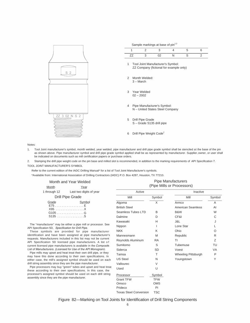
6Figure 82—Marking on Tool Joints for Identification of Drill String Components
Sample markings at base of pin1,2
1 2 3 4 5 6
ZZ 3 02 N S 2
1 Tool Joint Manufacturer's Symbol:ZZ Company (fictional for example only)
2 Month Welded:3 – March
3 Year Welded02 – 2002
4 Pipe Manufacturer's Symbol:N – United States Steel Company
5 Drill Pipe GradeS – Grade S135 drill pipe
6 Drill Pipe Weight Code2
Notes:
1. Tool Joint manufacturer's symbol, month welded, year welded, pipe manufacturer and drill pipe grade symbol shall be stenciled at the base of the pinas shown above. Pipe manufacturer symbol and drill pipe grade symbol applied shall be as represented by manufacturer. Supplier, owner, or user shallbe indicated on documents such as mill certification papers or purchase orders.
2. Stamping the drill pipe weight code on the pin base and milled slot is recommended, in addition to the marking requirements of API Specification 7.
TOOL JOINT MANUFACTURER'S SYMBOL
Refer to the current edition of the IADC Drilling Manual* for a list of Tool Joint Manufacturer's symbols.
*Available from: International Association of Drilling Contractors (IADC) P.O. Box 4287, Houston, TX 77210.
Pipe Manufacturers(Pipe Mills or Processors)
Active Inactive
Mill Symbol Mill Symbol
Month and Year WeldedMonth Year
1 through 12 Last two digits of year
Drill Pipe GradeGrade SymbolE75 . . . . . . . . . . . . . . . . . EX95 . . . . . . . . . . . . . . . . .XG105 . . . . . . . . . . . . . . . . S135 . . . . . . . . . . . . . . . .S
Algoma
British Steel
Seamless Tubes LTD
Dalmine
Kawasaki
Nippon
NKK
Mannesmann
Reynolds Aluminum
Sumitomo
Siderca
Tamsa
US Steel
Vallourec
Used
X
B
D
H
I
K
M
RA
S
SD
T
N
V
U
Armco
American Seamless
B&W
CF&I
J&L
Lone Star
Ohio
Republic
TI
Tubemuse
Voest
Wheeling Pittsburgh
Youngstown
A
AI
W
C
J
L
O
R
Z
TU
VA
P
Y
Processor Symbol
The "manufacturer" may be either a pipe mill or processor. SeeAPI Specification 5D, Specification for Drill Pipe.
These symbols are provided for pipe manufactureridentification and have been assigned at pipe manufacturer'srequests. Manufacturers included in this list may not be currentAPI Specification 5D licensed pipe manufacturers. A list o fcurrent licensed pipe manufacturers is available in the CompositeList of Manufacturers. (Licensed for Use of the API Monogram).
Pipe mills may upset and heat treat their own drill pipe, or theymay have this done according to their own specifications. Ineither case, the mill's assigned symbol should be used on eachdrill string assembly since they are the pipe manufacturer.
Pipe processors may buy "green" tubes and upset and heat treatthese according to their own specifications. In this case, theprocessor's assigned symbol should be used on each drill stringassembly since they are the pipe manufacturer.
Grant TFWOmscoPrideco
TFWOMS
PI
Texas Steel Conversion
G
TSC
RECOMMENDED PRACTICE FOR DRILL STEM DESIGN AND OPERATING LIMITS 7
Figure 83—Recommended Practice for Mill Slot and Groove Method of Drill String Identification
Drill Pipe Weight Code
(1) (2) (3) (4) (1) (2) (3) (4)Size OD Nominal Weight Wall Thickness Weight Code Size OD Nominal Weight Wall Thickness Weight Codeinches lb per ft inches Number inches lb per ft inches Number23/8 4.85 .190 1 41/2 20.00 .430 3
6.65* .280 2 22.82 .500 424.66 .550 5
27/8 6.85 .217 1 25.50 .575 610.40* .362 2
5 16.25 .296 131/2 9.50 .254 1 19.50* .362 2
13.30* .368 2 25.60 .500 315.50 .449 3
51/2 19.20 .304 14 11.85 .262 1 21.90* .361 2
14.00* .330 2 24.70 .415 315.70 .380 3
65/8 25.20* .330 241/2 13.75 .271 1 27.70 .362 3
16.60* .337 2*Designates standard weight for drill pipe size.
Depth *
allowance (TYP.)for of hardfacing
to hardfacing
45°
1 ±
Heavy weight grade E75 drill pipe
ZZ
6 0
2 N
E 3
* Groove and milled slot to be deep on 5 O.D. and larger tool joints, deep on 5" O.D. and smaller tool joints.
Stencil milled slot with high characters so marking may be read with drill pipe hanging in elevators.
Stamping the drill pipe weight code on the pin base and milled slot is recommended, in addition to the marking requirements of API Specification 7.
Heavy weight high strength drill pipewith hardfacing allowance
ZZ
3 0
2 N
S 3
Pipe grade code
Allowance for serial number (optional)
Standard weight high strength drill pipe
Pipe weight code
R 3/8"
R 1/16" TYP.
ZZ
6 0
2 N
S 2
Standard weight grade E75 drill pipe
ZZ
6 0
2 N
E 2
Heavy weight high strength drill pipe
ZZ
6 0
2 N
S 3
** When pin hardfacing is required, increase these dimensions by the length of the hardfacing allowance. See example above.
7/16'' 1/16''**
1 ±7/16''
11/2''
/16''**1
±3/8'' /16''**1
±3/8'' /8''1
±3/8'' /16''**1
±3/8'' /16''**1
±3/8'' /16''1
± 1'' /8''1
/4''1 /4''1
/16''3
/4''1
17/8'' hardfacing
8 API RECOMMENDED PRACTICE 7G—ADDENDUM 1
Page 127, replace Section 14 with the following:
14 Special Processes14.1 DRILL STEM SPECIAL PROCESSES
14.1.1 Usually the materials used in the manufacture of down hole drilling equipment (tool joints, drill collars, stabilizers andsubs) are AISI–4135, 4137, 4140, or 4145 steels.
14.1.2 These are alloy steels and are normally in the heat treated state, these materials are not weldable unless proper proce-dures are used to prevent cracking and to recondition the sections where welding has been performed.
14.1.3 It should be emphasized that areas welded can only be reconditioned and cannot be restored to their original state free ofmetallurgical change unless a complete heat treatment is performed after welding, which cannot be done in the field.
14.2 CONNECTION BREAK-IN
Based on field experience, it has been observed that used rotary shouldered connections are less likely to gall than new connec-tions. It is believed that this is due to work hardening the connection surfaces. The process of Connection Break-In is a make-upand break-out of the connection under controlled conditions in order to provide surface work hardening prior to use. ConnectionBreak-In may be done on the rig, as an optional manufacturing step, or at a service facility.
Since many factors effect connection galling, Connection Break-In does not eliminate the possibility of galling.
14.2.1 Preparation for Connection Break-In
Remove any storage or rust preventative coatings. Make sure that the connections are free of dirt or other debris. Thoroughlycoat the threads and shoulders of both pin and box connections with a thread compound suitable for rotary shouldered connec-tions. Determine the recommended make-up torque of the connection. Make note of the friction factor of the thread compoundand any adjustment required to the applied make up torque. See API Specification 7, Appendix G and API Recommended Practice7A1 for further information on thread compounds and friction factor.
14.2.2 Connection Break-In at the Rig
Taking care to align the connection, stab and make-up the connection slowly. Spinning in with a chain or high speed powerspinner may cause galling. Using a calibrated torque gage or line pull indicator, slowly make-up to the recommended make-uptorque. With manual tongs, use both sets of tongs and keep lines at 90 degrees for the final torque. Slowly break-out the connec-tion. During both make-up and break-out, watch for excessive resistance or other signs that could indicate the possibility of gall-ing. Wipe clean the pin and box connections and visually inspect for evidence of galling in the threads or sealing shoulders. Ifgalling occurs, rework the connection prior to use.
14.2.3 Connection Break-In During Manufacturing
When performing break-in at the factory or service facility, the connection should be finished machined, inspected, cold rolled(if specified) and preferably coated with an anti-gall material such as a phosphate or copper.
Note: Break-in will change thread gage standoff.
Slowly make-up three times to the recommended torque. Between each make-up, break-out only far enough to apply additional thread compound to the shoulders and last engaged threads. Break out the connection after final make-up. Wipe clean the pin and box and visually inspect for galling on the threads or shoulder. If galling occurs, the connection is rejected.
Page 130, Table 33, add the following sizes:
Page 130, Table 33, Note:
Change “A.8” to “A.9”
Replace Appendix A with the following:
Connection
Maximum Pin ID
in.
Bit Sub OD in.
Minimum Make-up Torque
ft-lb
1 API REG 0.75 1.56 18511/2 API REG 1.00 2.00 665
9
APPENDIX A— STRENGTH AND DESIGN FORMULAS
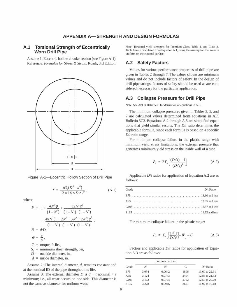
A.1 Torsional Strength of Eccentrically Worn Drill Pipe
Assume 1: Eccentric hollow circular section (see Figure A-1).Reference: Formulas for Stress & Strain, Roark, 3rd Edition.
, (A.1)
where
F =
N = d/D,
φ = ,
T = torque, ft-lbs.,Ss = minimum shear strength, psi,D = outside diameter, in.,d = inside diameter, in.
Assume 2: The internal diameter, d, remains constant andat the nominal ID of the pipe throughout its life.
Assume 3: The external diameter D is d + t nominal + tminimum; i.e., all wear occurs on one side. This diameter isnot the same as diameter for uniform wear.
Note: Torsional yield strengths for Premium Class, Table 4, and Class 2,Table 6 were calculated from Equation A.1, using the assumption that wear isuniform on the external surface.
A.2 Safety FactorsValues for various performance properties of drill pipe are
given in Tables 2 through 7. The values shown are minimumvalues and do not include factors of safety. In the design ofdrill pipe strings, factors of safety should be used as are con-sidered necessary for the particular application.
A.3 Collapse Pressure for Drill PipeNote: See API Bulletin 5C3 for derivation of equations in A.3.
The minimum collapse pressures given in Tables 3, 5, and7 are calculated values determined from equations in APIBulletin 5C3. Equations A.2 through A.5 are simplified equa-tions that yield similar results. The D/t ratio determines theapplicable formula, since each formula is based on a specificD/t ratio range.
For minimum collapse failure in the plastic range withminimum yield stress limitations: the external pressure thatgenerates minimum yield stress on the inside wall of a tube.
(A.2)
Applicable D/t ratios for application of Equation A.2 are asfollows:
For minimum collapse failure in the plastic range:
(A.3)
Factors and applicable D/t ratios for application of Equa-tion A.3 are as follows:
Figure A-1—Eccentric Hollow Section of Drill Pipe
e
d
D
TπSs D4 d4–( )
12 16× D× F×--------------------------------------=
1 4N2φ1 N2–( )
------------------- 32N2φ2
1 N2–( ) 1 N4–( )------------------------------------------+ +
+ 48N2 1 2N2 3N4 2N6+ + +( )φ3
1 N2–( ) 1 N4–( ) 1 N6–( )------------------------------------------------------------------------ ,
eD----
Grade D/t Ratio
E75 . . . . . . . . . . . . . . . . . . . . . . . . . . . . . . . . . . . . . . . . . . . . . . 13.60 and less
X95. . . . . . . . . . . . . . . . . . . . . . . . . . . . . . . . . . . . . . . . . . . . . . . 12.85 and less
G105. . . . . . . . . . . . . . . . . . . . . . . . . . . . . . . . . . . . . . . . . . . . . . 12.57 and less
S135 . . . . . . . . . . . . . . . . . . . . . . . . . . . . . . . . . . . . . . . . . . . . . . 11.92 and less
Formula Factors
Grade A' B' C D/t Ratio
E75 3.054 0.0642 1806 13.60 to 22.91X95 3.124 0.0743 2404 12.85 to 21.33G105 3.162 0.0794 2702 12.57 to 20.70S135 3.278 0.0946 3601 11.92 to 19.18
Pc 2YmD t⁄( ) 1–
D t⁄( )2-----------------------=
Pc YmA'
D t⁄---------
B'– C–=
10 API RECOMMENDED PRACTICE 7G—ADDENDUM 1
For minimum collapse failure in conversion or transitionzone between elastic and plastic range:
(A.4)
Factors and applicable D/t ratios for application of Equa-tion A.4 are as follows:
For minimum collapse failure in the elastic range:
(A.5)
Applicable D/t ratios for application of Equation A.5 are asfollows:
wherePc = minimum collapse pressure, psi,
*D = nominal outside diameter, in.,*t = nominal wall thickness, in.,
Ym = material minimum yield strength, psi.
Notes:*Collapse pressures for used drill pipe are determined by adjusting the nomi-nal outside diameter, D, and wall thickness, t, as if the wear is uniform on theoutside of the pipe body and the inside diameter remains constant. Values ofD and t for each class of used drill pipe follow. These values are to be used inapplicable Equation A.2, A.3, A.4, or A.5, depending on the D/t ratio, todetermine collapse pressure.
Premium Class: t = (0.80) (nominal wall), D = nominal OD – (0.40) (nom-inal wall)
Class 2: t = (0.70) (nominal wall), D = nominal OD – (0.60) (nominal wall)
A.4 Free Length of Stuck Pipe
The relation between differential stretch and free length ofa stuck string of steel pipe due to a differential pull is:
, (A.6)
whereL1 = length of free drill pipe, ft.,E = modulus of elasticity, lb/in.,2
e = differential stretch, in.,WdP = weight per foot of pipe, lbs/ft.,
P = differential pull, lbs.
Where E = 30 x 106, this formula becomes:
(A.7)
A.5 Internal PressureA.5.1 DRILL PIPE
, (A.8)
wherePi = internal pressure, psi,Ym = material minimum yield strength, psi,
t = remaining wall thickness of tube, in.,D = nominal outside diameter of tube, in.
Notes:1. Internal pressures for new drill pipe in Table 3 were determined by using thenominal wall thickness for t in the above equation and multiplying by the factor0.875 due to permissible wall thickness tolerance of minus 121/2 percent.2. Internal pressures for used drill pipe were determined by adjusting thenominal wall thickness according to footnotes below Table 5 and 7 and usingthe nominal outside diameter, in the above Equation A.8.
A.5.2 KELLYS
, (A.9)
wherePi = internal pressure, psi,Ym = material minimum yield strength, psi,
DFL = distance across drive section flats, in.,t = minimum wall, in.
Note: The dimension t is the minimum wall thickness of the drive section andmust be determined in each case through the use of an ultrasonic thicknessgauge or similar device.
A.6 Stretch of Suspended Drill PipeWhen pipe is freely suspended in a fluid, the stretch due to
its own weight is:
, (A.10)
wheree = stretch, in.,
L1 = length of free drill pipe, ft.,
Formula Factors
Grade A B D/t Ratio
E75 1.990 0.0418 22.91 to 32.05X95 2.029 0.0482 21.33 to 28.36G105 2.053 0.0515 20.70 to 26.89S135 2.133 0.0615 19.18 to 23.44
Grade D/t Ratio
E75. . . . . . . . . . . . . . . . . . . . . . . . . . . . . . . . . . . . . . . . . . . . 32.05 and greater
X95 . . . . . . . . . . . . . . . . . . . . . . . . . . . . . . . . . . . . . . . . . . . .28.36 and greater
G105 . . . . . . . . . . . . . . . . . . . . . . . . . . . . . . . . . . . . . . . . . . .26.89 and greater
S135 . . . . . . . . . . . . . . . . . . . . . . . . . . . . . . . . . . . . . . . . . . . .23.44 and greater
Pc YmA
D t⁄---------
B–=
Pc46.95 106×
D t⁄( ) D t⁄( ) 1–[ ] 2--------------------------------------------=
98
L1E e× Wdp×
40.8 P---------------------------=
L1735,294 e× WdP×
P-------------------------------------------=
Pi2Ymt
D-----------= 98
PiYm DFL
2 DFL 2t–( )2–[ ]
3 DFL( )4 DFL 2t–( )4+-------------------------------------------------------= 98
eL1
2
24E---------- Wa 2Wf– 1 µ–( )[ ]=
98
RECOMMENDED PRACTICE FOR DRILL STEM DESIGN AND OPERATING LIMITS 11
E = modulus of elasticity, psi,Wa = weight of pipe material, lb/cu ft.,Wf = weight of fluid, lb/cu ft.,µ = Poisson’s ratio.
For steel pipe where Ws = 489.5 lb/cu ft, E = 30 x 106 psiand µ = 0.28, this formula will be:
, (A.11)
or
, (A.12)
whereWf = weight of fluid, lb/cu ft.,Wg = weight of fluid, lb/gal.
A.7 Tensile Strength of Drill Pipe Body
P = Ym A, (A.13)
whereP = minimum tensile strength, lbs.,
Ym = material minimum yield strength, psi,A = cross-section area, sq. in. (Table 1, Column 6, for
drill pipe).
A.8 Torsional Yield Strength of Drill Pipe Body
A.8.1 PURE TORSION
, (A.14)
whereQ = minimum torsional yield strength, ft-lb.,
Ym = material minimum yield strength, psi,J = polar moment of inertia
= (D4 – d4) for tubes
= 0.098175 (D4 – d4),D = outside diameter, in.,d = inside diameter, in.
00
eL1
2
72 107×-------------------- 489.5 1.44Wf–[ ]=
eL1
2
9.625 107×--------------------------- 65.44 1.44Wg–[ ]=
03
3/4
5/8 3/8
AB
Rs
ID
QC
AP
Rt
Pin
Box
p
C Lt 2
Lt 2
θ θ
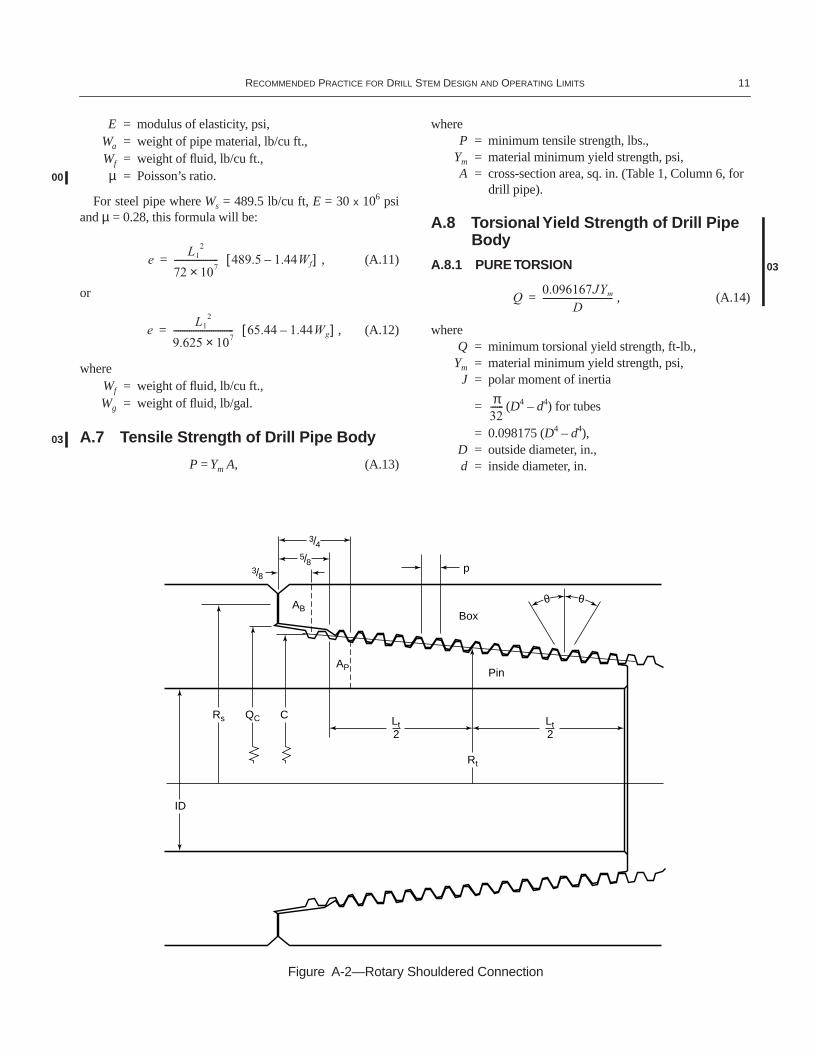
Figure A-2—Rotary Shouldered Connection
Q0.096167JYm
D-------------------------------=
03
π32------
12 API RECOMMENDED PRACTICE 7G—ADDENDUM 1
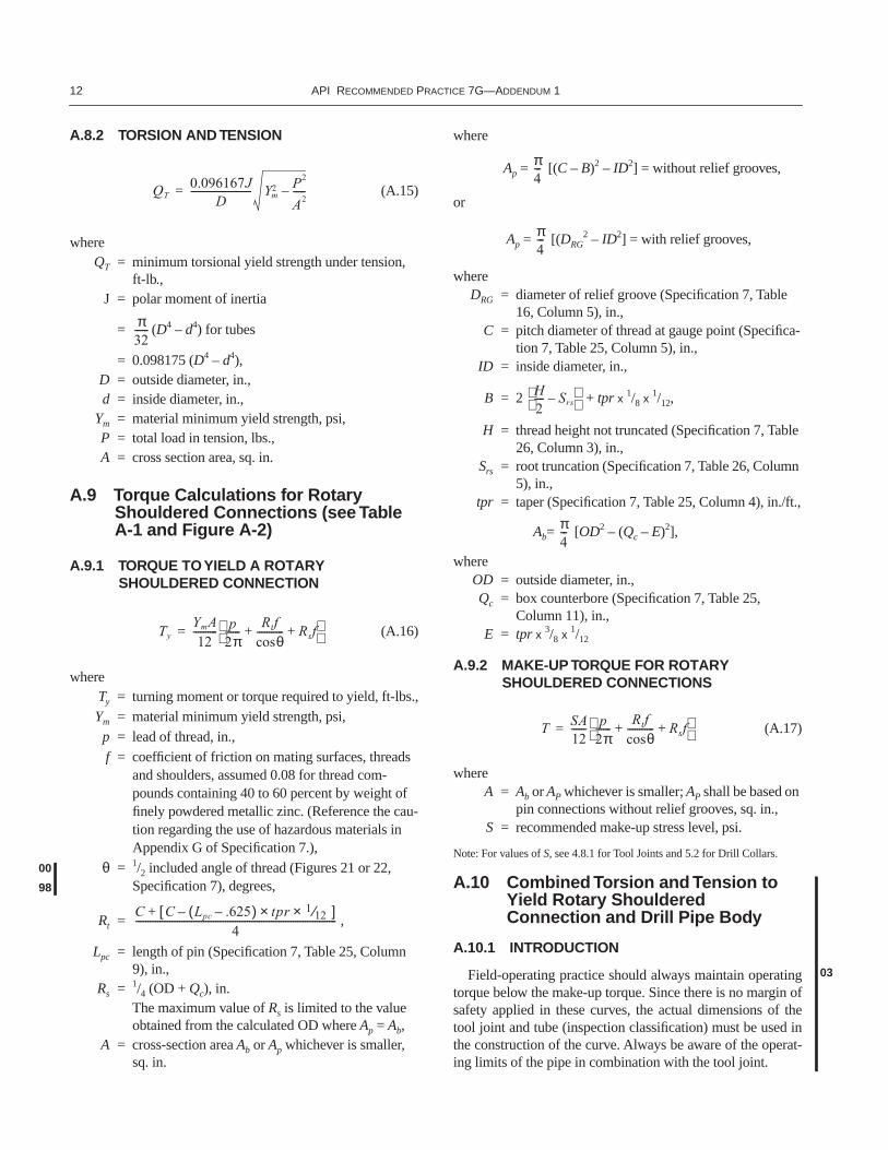
A.8.2 TORSION AND TENSION
(A.15)
whereQT = minimum torsional yield strength under tension,
ft-lb.,J = polar moment of inertia
= (D4 – d4) for tubes
= 0.098175 (D4 – d4),D = outside diameter, in.,d = inside diameter, in.,
Ym = material minimum yield strength, psi,P = total load in tension, lbs.,A = cross section area, sq. in.
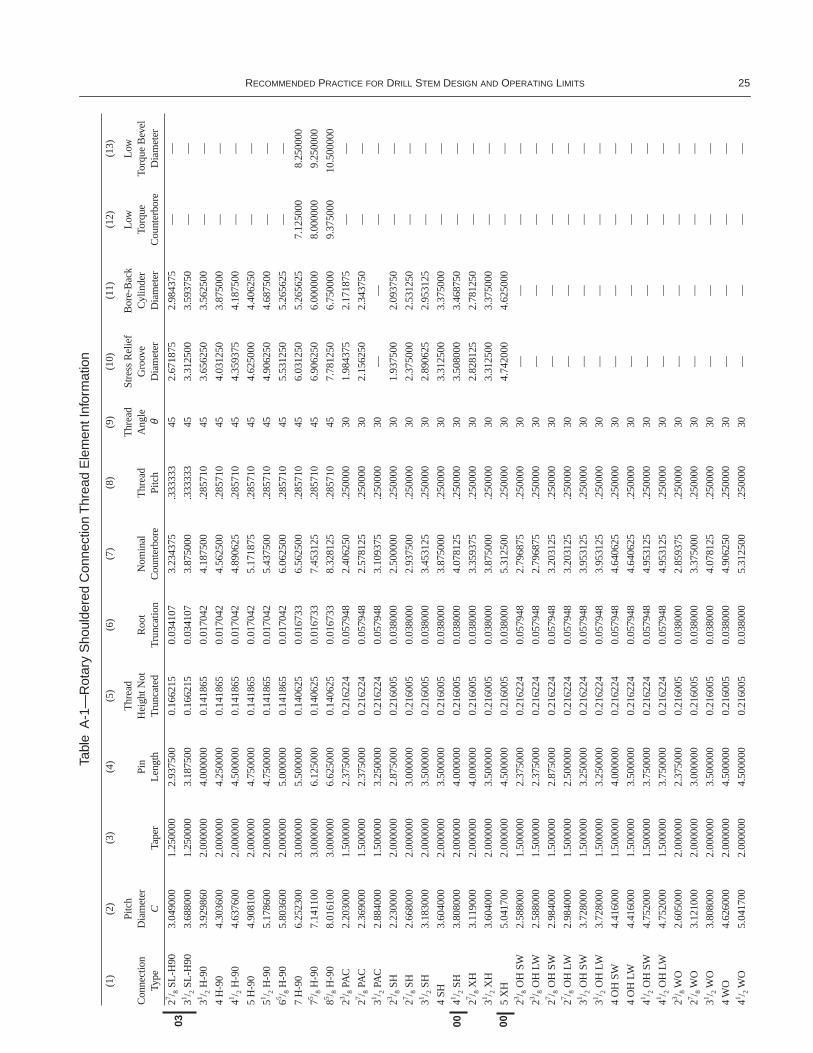
A.9 Torque Calculations for Rotary Shouldered Connections (see Table A-1 and Figure A-2)
A.9.1 TORQUE TO YIELD A ROTARY SHOULDERED CONNECTION
(A.16)
whereTy = turning moment or torque required to yield, ft-lbs.,Ym = material minimum yield strength, psi,
p = lead of thread, in.,f = coefficient of friction on mating surfaces, threads
and shoulders, assumed 0.08 for thread com-pounds containing 40 to 60 percent by weight of finely powdered metallic zinc. (Reference the cau-tion regarding the use of hazardous materials in Appendix G of Specification 7.),
θ = 1/2 included angle of thread (Figures 21 or 22, Specification 7), degrees,
Rt = ,
Lpc = length of pin (Specification 7, Table 25, Column 9), in.,
Rs = 1/4 (OD + Qc), in.The maximum value of Rs is limited to the value obtained from the calculated OD where Ap = Ab,
A = cross-section area Ab or Ap whichever is smaller, sq. in.
where
Ap = [(C – B)2 – ID2] = without relief grooves,
or
Ap = [(DRG2 – ID2] = with relief grooves,
whereDRG = diameter of relief groove (Specification 7, Table
16, Column 5), in.,C = pitch diameter of thread at gauge point (Specifica-
tion 7, Table 25, Column 5), in.,ID = inside diameter, in.,
B = 2 + tpr x 1/8 x 1/12,
H = thread height not truncated (Specification 7, Table 26, Column 3), in.,
Srs = root truncation (Specification 7, Table 26, Column 5), in.,
tpr = taper (Specification 7, Table 25, Column 4), in./ft.,
Ab= [OD2 – (Qc – E)2],
whereOD = outside diameter, in.,Qc = box counterbore (Specification 7, Table 25,
Column 11), in.,E = tpr x 3/8 x 1/12
A.9.2 MAKE-UP TORQUE FOR ROTARY SHOULDERED CONNECTIONS
(A.17)
whereA = Ab or AP whichever is smaller; AP shall be based on
pin connections without relief grooves, sq. in.,S = recommended make-up stress level, psi.
Note: For values of S, see 4.8.1 for Tool Joints and 5.2 for Drill Collars.
A.10 Combined Torsion and Tension to Yield Rotary Shouldered Connection and Drill Pipe Body
A.10.1 INTRODUCTION
Field-operating practice should always maintain operatingtorque below the make-up torque. Since there is no margin ofsafety applied in these curves, the actual dimensions of thetool joint and tube (inspection classification) must be used inthe construction of the curve. Always be aware of the operat-ing limits of the pipe in combination with the tool joint.
QT0.096167J
D------------------------- Ym
2 P2
A2-----–=
π32------
TyYmA12
---------- p2π------
Rtfcosθ----------- Rsf+ +
=
00
98
C C Lpc .625–( )– tpr× 112⁄×[ ]+
4-----------------------------------------------------------------------------------
π4---
π4---
H2---- Srs–
π4---
T SA12------ p
2π------
Rtfcosθ----------- Rsf+ +
=
03
RECOMMENDED PRACTICE FOR DRILL STEM DESIGN AND OPERATING LIMITS 13
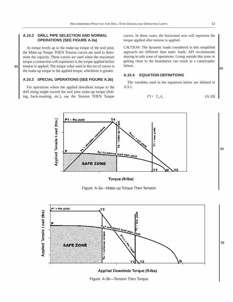
A.10.2 DRILL PIPE SELECTION AND NORMAL OPERATIONS (SEE FIGURE A.3a)
At torque levels up to the make-up torque of the tool joint,the Make-up Torque THEN Tension curves are used to deter-mine the capacity. These curves are used when the maximumtorque a connection will experience is the torque applied beforetension is applied. The torque value used in this set of curves isthe make-up torque or the applied torque, whichever is greater.
A.10.3 SPECIAL OPERATIONS (SEE FIGURE A.3b)
For operations where the applied downhole torque to thedrill string might exceed the tool joint make-up torque (fish-ing, back-reaming, etc.), use the Tension THEN Torque
curves. In these cases, the horizontal axis will represent thetorque applied after tension is applied.
CAUTION: The dynamic loads considered in this simplifiedapproach are different than static loads. API recommendsstaying in safe zone of operations. Going outside this zone orgetting close to the boundaries can result in a catastrophicfailure.
A.10.4 EQUATION DEFINITIONS
The variables used in the equations below are defined inA.9.1.
(A.18)
0303
P1 YmAp=
Figure A-3a—Make-up Torque Then Tension
Figure A-3b—Tension Then Torque
03
03
14 API RECOMMENDED PRACTICE 7G—ADDENDUM 1
(A.19)
(A.20)
(A.21)
(A.22)
(A.23)
(A.24)
(A.25)
(A.26)
A description of the values calculated above and those usedto plot the curves are:
Ta = torque that is applied to the tool joint before ten-sion is applied, make-up torque, ft-lbs
TDH = applied downhole torque, ft-lbsP1 = yield strength of the tool joint pin at 5/8" from the
make-up shoulder, lbsPo = tension required to separate the tool joint shoul-
ders after Ta is applied, lbs. Po is represented by the line from the origin to the point T4. Do not use this formula if Ta is greater than T4 since Po will be greater than P1
PT4T2 = tension required to yield pin after Ta is applied, lbs. PT4T2 is represented by the line from T4 to T2
PT3T2 = tension required to yield pin after TDH is applied, lbs. PT3T2 is represented by the line from T3 to T2
T1 = torsional strength of the box of the tool joint and is represented by a vertical line at that value on the x-axis, ft-lbs
T2 = torsional strength of the pin of the tool joint, ft-lbsT3 = torsional load required to produce additional make-
up of the connection when the shoulders are sepa-rated by an external tensile load on the pipe that produces yield stress in the tool joint pin, ft-lbs
T4 = make-up torque at which pin yield and shoulder separation occur simultaneously with an exter-nally applied tensile load, ft-lbs
PQ = yield of the drill pipe tube in the presence of tor-sion represented by the elliptical curve, lbs. Equa-tion was produced by rearranging Equation A.15
A.10.5 FAILURE MODES
The failure modes under combined torsion/tension loads are: 1. Pin yield.2. Box yield.3. Shoulder separation (seal failure).4. Tube yield.
A.10.6 USING THE CURVES
Calculate the above values using the actual dimensions ofthe tool joints and tube. Use these values to plot a workingcurve.
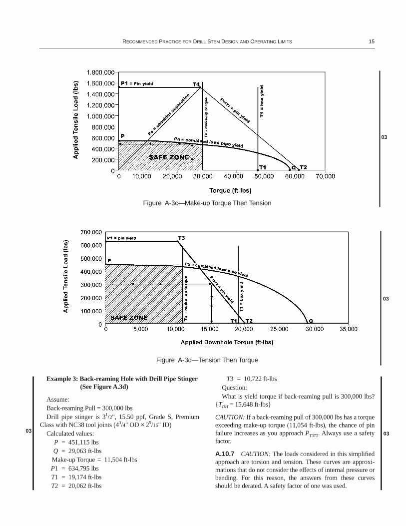
Example 1: Drilling an Extended Reach Well (See Figure A.3c)
Assume:Anticipated Maximum Drilling Torque = 25,000 ft-lbsDrill Pipe string is 5", 19.50 ppf, Grade S, Premium Class
with NC50 tool joints (65/16" OD × 23/4" ID) Calculated values:
P = 560,764 lbsQ = 58,113 ft-lbsTa (make-up torque) = 28,381ft-lbs
P1 = 1,532,498 lbs T1 = 47,302 ft-lbsT2 = 62,608 ft-lbsT4 = 26,945 ft-lbs
QuestionsIs the drill pipe string adequate for the anticipated torque?
{{Yes}}What is the allowable hook load at anticipated maximum
drilling torque? {{P = 504,772 lbs at 25,000 ft-lbs}}
Example 2: Fishing Drill Pipe String in Example 1(See Figure A.3c)
Question:What is the maximum pull without exceeding yield
strength in the absence of torque? {{With a straight pull andno torque, the maximum pull is the tensile capacity of thetube which is P = 560,764 lbs.}}
Po12 Ab Ap+( )Ta
Abp
2π------
Rt fθcos
------------ Rs f+ +
--------------------------------------------------=
PT4T2 Ab Ap+( ) YmTa12
App
2π------
Rt fθcos
------------ Rs f+ +
--------------------------------------------------–
=
PT3T2
YmApp
2π------
Rt fθcos
------------ Rs f+ + 12TDH–
Rs f------------------------------------------------------------------------------=
T1Ym
12------
Abp
2π------
Rt fθcos
------------ Rs f+ + =
T2Ym
12------
App
2π------
Rt fθcos
------------ Rs f+ + =
T3Ym
12------
App
2π------
Rt fθcos
------------+ =
T4Ym
12------
Ap Ab
Ap Ab+-----------------
p2π------
Rt fθcos
------------ Rs f+ + =
PQ A Ym2 QtD
0.096167 J⋅-----------------------------
2
–=
0303
RECOMMENDED PRACTICE FOR DRILL STEM DESIGN AND OPERATING LIMITS 15
Example 3: Back-reaming Hole with Drill Pipe Stinger(See Figure A.3d)
Assume:Back-reaming Pull = 300,000 lbsDrill pipe stinger is 31/2", 15.50 ppf, Grade S, Premium
Class with NC38 tool joints (43/4" OD × 29/16" ID) Calculated values:
P = 451,115 lbsQ = 29,063 ft-lbsMake-up Torque = 11,504 ft-lbsP1 = 634,795 lbs T1 = 19,174 ft-lbsT2 = 20,062 ft-lbs
T3 = 10,722 ft-lbsQuestion:What is yield torque if back-reaming pull is 300,000 lbs?
{TDH = 15,648 ft-lbs}
CAUTION: If a back-reaming pull of 300,000 lbs has a torqueexceeding make-up torque (11,054 ft-lbs), the chance of pinfailure increases as you approach PT3T2. Always use a safetyfactor.
A.10.7 CAUTION: The loads considered in this simplifiedapproach are torsion and tension. These curves are approxi-mations that do not consider the effects of internal pressure orbending. For this reason, the answers from these curvesshould be derated. A safety factor of one was used.
Figure A-3c—Make-up Torque Then Tension
Figure A-3d—Tension Then Torque
03
03
03
03
16 API RECOMMENDED PRACTICE 7G—ADDENDUM 1
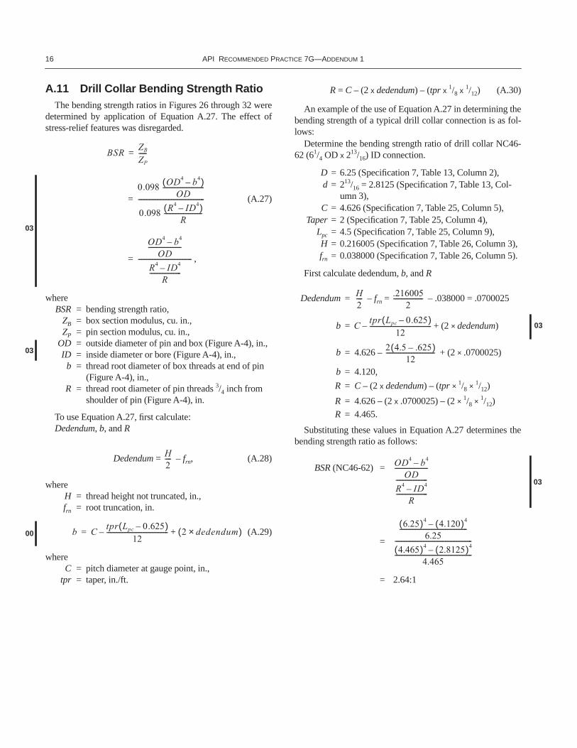
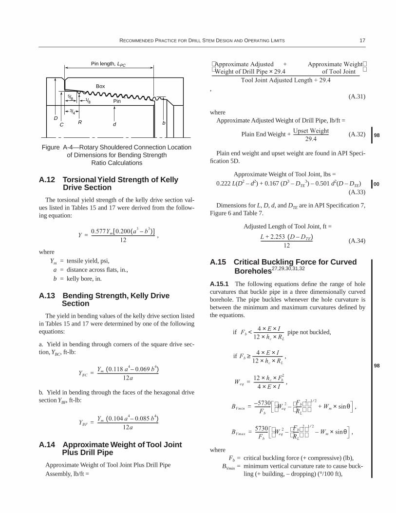
A.11 Drill Collar Bending Strength RatioThe bending strength ratios in Figures 26 through 32 were
determined by application of Equation A.27. The effect ofstress-relief features was disregarded.
(A.27)
,
whereBSR = bending strength ratio,
ZB = box section modulus, cu. in.,ZP = pin section modulus, cu. in.,
OD = outside diameter of pin and box (Figure A-4), in.,ID = inside diameter or bore (Figure A-4), in.,
b = thread root diameter of box threads at end of pin (Figure A-4), in.,
R = thread root diameter of pin threads 3/4 inch from shoulder of pin (Figure A-4), in.
To use Equation A.27, first calculate:Dedendum, b, and R
Dedendum = – frn, (A.28)
whereH = thread height not truncated, in.,frn = root truncation, in.
(A.29)
whereC = pitch diameter at gauge point, in.,
tpr = taper, in./ft.
R = C – (2 x dedendum) – (tpr x 1/8 x 1/12) (A.30)
An example of the use of Equation A.27 in determining thebending strength of a typical drill collar connection is as fol-lows:
Determine the bending strength ratio of drill collar NC46-62 (61/4 OD x 213/16) ID connection.
D = 6.25 (Specification 7, Table 13, Column 2),d = 213/16 = 2.8125 (Specification 7, Table 13, Col-
umn 3),C = 4.626 (Specification 7, Table 25, Column 5),
Taper = 2 (Specification 7, Table 25, Column 4),Lpc = 4.5 (Specification 7, Table 25, Column 9),H = 0.216005 (Specification 7, Table 26, Column 3),frn = 0.038000 (Specification 7, Table 26, Column 5).
First calculate dedendum, b, and R
Dedendum = – frn = – .038000 = .0700025
b = + (2 × dedendum)
b = 4.626 – + (2 × .0700025)
b = 4.120,
R = C – (2 x dedendum) – (tpr × 1/8 × 1/12)
R = 4.626 – (2 x .0700025) – (2 × 1/8 × 1/12)
R = 4.465.
Substituting these values in Equation A.27 determines thebending strength ratio as follows:
BSR (NC46-62) =
=
= 2.64:1
BSRZB
ZP
-----=
0.098 OD4 b4–( )OD
--------------------------
0.098 R4 ID4–( )R
------------------------
------------------------------------------=
03
OD4 b4–OD
---------------------
R4 ID4–R
--------------------
----------------------------------=
03
H2----
b Ctpr Lpc 0.625–( )
12---------------------------------------– 2 dedendum×( )+=00
H2---- .216005
2-------------------
Ctpr Lpc 0.625–( )
12---------------------------------------– 03
2 4.5 .625–( )12
-------------------------------
OD4 b4–OD
R4 ID4–R
--------------------
-----------------------------------------
03
6.25( )4 4.120( )4–6.25
-------------------------------------------
4.465( )4 2.8125( )4–-------------------------------------------------
4.465-------------------------------------------------
RECOMMENDED PRACTICE FOR DRILL STEM DESIGN AND OPERATING LIMITS 17
A.12 Torsional Yield Strength of Kelly Drive Section
The torsional yield strength of the kelly drive section val-ues listed in Tables 15 and 17 were derived from the follow-ing equation:
,
whereYm = tensile yield, psi,
a = distance across flats, in.,b = kelly bore, in.
A.13 Bending Strength, Kelly Drive Section
The yield in bending values of the kelly drive section listedin Tables 15 and 17 were determined by one of the followingequations:
a. Yield in bending through corners of the square drive sec-tion, YBC, ft-lb:
b. Yield in bending through the faces of the hexagonal drivesection YBF, ft-lb:
A.14 Approximate Weight of Tool Joint Plus Drill Pipe
Approximate Weight of Tool Joint Plus Drill PipeAssembly, lb/ft =
,(A.31)
whereApproximate Adjusted Weight of Drill Pipe, lb/ft =
Plain End Weight + (A.32)
Plain end weight and upset weight are found in API Speci-fication 5D.
Approximate Weight of Tool Joint, lbs =
0.222 L(D2 – d2) + 0.167 (D3 – DTE3) – 0.501 d2(D – DTE)
(A.33)
Dimensions for L, D, d, and DTE are in API Specification 7,Figure 6 and Table 7.
Adjusted Length of Tool Joint, ft =
(A.34)
A.15 Critical Buckling Force for Curved Boreholes27,29,30,31,32
A.15.1 The following equations define the range of holecurvatures that buckle pipe in a three dimensionally curvedborehole. The pipe buckles whenever the hole curvature isbetween the minimum and maximum curvatures defined bythe equations.
if pipe not buckled,
if ,
,
,
,
whereFb = critical buckling force (+ compressive) (lb),
BVmin = minimum vertical curvature rate to cause buck-ling (+ building, – dropping) (°/100 ft),
1/8 5/8
3/4
Pin
Box
Pin length, LPC
DC R d b
Figure A-4—Rotary Shouldered Connection Location of Dimensions for Bending Strength
Ratio Calculations
Y0.577Ym 0.200 a3 b3–( )[ ]
12-----------------------------------------------------------=
YBCYm 0.118 a4 0.069– b4( )
12a---------------------------------------------------------=
YBFYm 0.104 a4 0.085– b4( )
12a---------------------------------------------------------=
Approximate Adjusted Approximate Weight+Weight of Drill Pipe 29.4 of Tool Joint×
Tool Joint Adjusted Length + 29.4-----------------------------------------------------------------------------------------------------------------------------------------
Upset Weight29.4
--------------------------------- 98
00
L 2.253+ D DTE–( )12
------------------------------------------------
Fb4 E I××
12 hc× RL×----------------------------<
Fb4 E I××
12 hc× RL×----------------------------≥
98
Weq12 hc× Fb
2×4 E× I×
----------------------------=
BVmin5730–Fb
--------------- Weq2 Fb
RL
----- 2
– 1 2⁄
Wm+ θsin×=
BVmax5730
Fb
------------ Weq2 Fb
RL
----- 2
– 1 2⁄
Wm– θsin×=
18 API RECOMMENDED PRACTICE 7G—ADDENDUM 1
BVmax = maximum vertical curvature rate that buckles pipe (+ building, – dropping) (°/100 ft),
Weq = equivalent pipe weight required to buckle pipe at Fb axial load,
E = 29.6 x 10⁶ psi,
I = ,
Wm = buoyant weight of pipe (lb/ft),
Wa = actual weight in air (lb/ft),MW = mud density (lb/gal),
hc = radial clearance of tool joint to
hole (in.),DH = diameter of hole (in.),
TJOD = OD tool joints (in.),
BL = lateral curvature rate (°/100 ft),
BT = total curvature rate (°/100 ft),
RL = lateral build radius (ft),
θ = inclination angle (deg).
A.15.2 If the hole curvature is limited to the vertical plane,the buckling equations simplify to the following:
,
,
,
whereBVmin = minimum vertical curvature rate for buckling
(+ building, – dropping) (°/100 ft),BVmax = maximum vertical curvature rate for buckling
(+ building, – dropping) (°/100 ft),Fb = buckling force (lb),E = 29.6 x 10⁶ (psi),
I = ,
Weq = buoyant weight equivalent for pipe in curved borehole (lb/ft),
Wm = buoyant weight of pipe (lb/ft),
Wa = actual weight of pipe in air (lb/ft),MW = mud density (lb/gal),
hc = radial clearance of tool joint to
hole (in.),DH = diameter of hole (in.),
TJOD = OD of tool joint (in.),θ = inclination angle (deg).
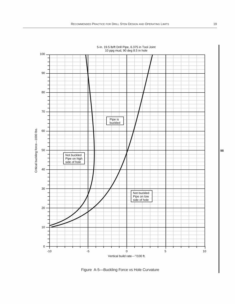
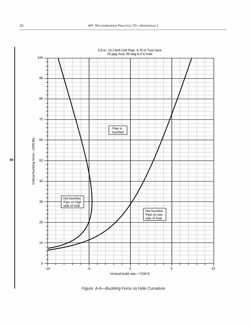
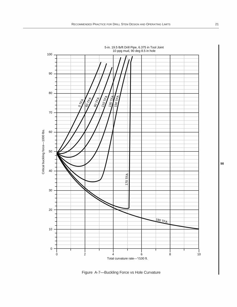
A.15.3 Figures A-5 and A-6 show the effect of hole curva-ture on the buckling force for 5-inch and 31⁄2-inch drillpipe.Figure A-7 shows the effect of lateral curvatures on the buck-ling force of 5-inch drillpipe. For lateral and upward curva-tures, the critical buckling force increases with the totalcurvature rate.
A.16 Bending Stresses on Compressively Loaded Drillpipe in Curved Boreholes33,34
A.16.1 The type of loading can be determined by comparingthe actual hole curvature to calculated values of the critical cur-vatures that define the transition from no pipe body contact topoint contact and from point contact to wrap contact. The twocritical curvatures are computed from the following equations.
,
whereBc = the critical hole curvature that defines the tran-
sition from no pipe body contact to point con-tact (°/100 ft),
∆D = (TJOD – OD),TJOD = tool joint OD (in.),
OD = pipe body OD (in.),
J = (in.),
L = length of one joint of pipe (in.),E = Young’s modulus 30 x 106 for steel (psi),I = moment of inertia of pipe body (in.)
= ,
F = axial compressive load on pipe (lb),ID = pipe body ID (in.).
,
whereBw = the critical curvature that defines the transition
from point contact to wrap contact (°/100 ft),
0.7854 OD4 ID4–( )16
-----------------------------------------------
Wa65.5 MW–
65.5--------------------------
DH TJOD–2
----------------------------
BT2 BV
2–
5730BL
------------
Weq12 hc× Fb
2×4 E× I×
----------------------------=
BVmin5730 Weq Wm+ θsin×( )×–
Fb
-----------------------------------------------------------------=
BVmax5730 Weq Wm– θsin×( )×
Fb
--------------------------------------------------------------=
98
π64------ OD4 ID4–( )
Wa65.5 MW–
65.5--------------------------
DH TJOD–2
------------------------------
Bc57.3 100× 12× ∆D×
J L 57.3 L×4 J×
------------------- tan L
4 J×-----------–×
--------------------------------------------------------------------=
E I×F
----------- 1 2⁄
98
π OD4 ID4–( )64
---------------------------------
Bw57.3 100× 12× ∆D×
J L 4JL----- L
4J tan2 57.3L4J
-------------- ×
----------------------------------------- 2
tan 57.3L4J
--------------
---------------------------–+×
---------------------------------------------------------------------------------------------------------=
RECOMMENDED PRACTICE FOR DRILL STEM DESIGN AND OPERATING LIMITS 19
Figure A-5—Buckling Force vs Hole Curvature
Not buckledPipe on highside of hole
Not buckledPipe on lowside of hole
Pipe isbuckled
5-in. 19.5 lb/ft Drill Pipe, 6.375 in Tool Joint10 ppg mud, 90 deg 8.5 in hole
100
90
80
70
60
50
40
30
20
10
0
-10 -5 0 5 10
Vertical build rate—°/100 ft.
Crit
ical
buc
klin
g fo
rce—
1000
lbs.
98
20 API RECOMMENDED PRACTICE 7G—ADDENDUM 1
Figure A-6—Buckling Force vs Hole Curvature
Not buckledPipe on highside of hole
Not buckledPipe on lowside of hole
Pipe isbuckled
3.5-in. 13.3 lb/ft Drill Pipe, 4.75 in Tool Joint10 ppg mud, 90 deg 6.0 in hole
100
90
80
70
60
50
40
30
20
10
0
-10 -5 0 5 10
Vertical build rate—°/100 ft.
Crit
ical
buc
klin
g fo
rce—
1000
lbs.
98
RECOMMENDED PRACTICE FOR DRILL STEM DESIGN AND OPERATING LIMITS 21
Figure A-7—Buckling Force vs Hole Curvature
5-in. 19.5 lb/ft Drill Pipe, 6.375 in Tool Joint10 ppg mud, 90 deg 8.5 in hole
100
90
80
70
60
50
40
30
20
10
0
0 2 4 6 8 10Total curvature rate—°/100 ft.
Crit
ical
buc
klin
g fo
rce—
1000
lbs.
0 TF
A60
TFA
90 T
FA
110
TFA
130
TF
A15
0 T
FA
170
TF
A
180 TFA
98
22 API RECOMMENDED PRACTICE 7G—ADDENDUM 1
∆D = (TJOD – OD),TJOD = tool joint OD (in.),
OD = pipe body OD (in.),
J = (in.),
L = length of one joint of pipe (in.),E = Young’s modulus 30 x 106 for steel (psi),I = moment of inertia of pipe (in.4)
= ,
F = axial compressive load on pipe (lb),ID = pipe body ID (in.).
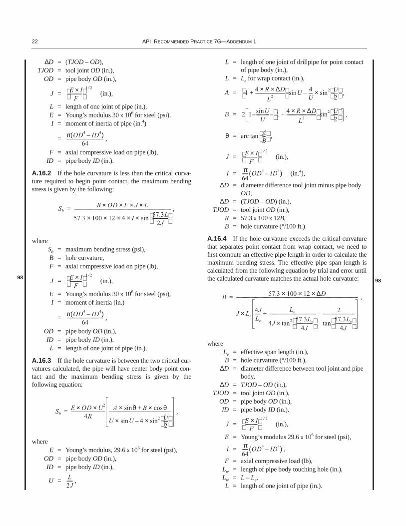
A.16.2 If the hole curvature is less than the critical curva-ture required to begin point contact, the maximum bendingstress is given by the following:
,
whereSb = maximum bending stress (psi),B = hole curvature,F = axial compressive load on pipe (lb),
J = (in.),
E = Young’s modulus 30 x 106 for steel (psi),I = moment of inertia (in.)
= ,
OD = pipe body OD (in.),ID = pipe body ID (in.).L = length of one joint of pipe (in.),
A.16.3 If the hole curvature is between the two critical cur-vatures calculated, the pipe will have center body point con-tact and the maximum bending stress is given by thefollowing equation:
,
whereE = Young’s modulus, 29.6 x 10⁶ for steel (psi),
OD = pipe body OD (in.),ID = pipe body ID (in.),
U = ,
L = length of one joint of drillpipe for point contact of pipe body (in.),
L = Le for wrap contact (in.),
A = ,
B = ,
θ = arc tan ,
J = (in.),
I = (in.4),
∆D = diameter difference tool joint minus pipe body OD,
∆D = (TJOD – OD) (in.),TJOD = tool joint OD (in.),
R = 57.3 x 100 x 12B,B = hole curvature (°/100 ft.).
A.16.4 If the hole curvature exceeds the critical curvaturethat separates point contact from wrap contact, we need tofirst compute an effective pipe length in order to calculate themaximum bending stress. The effective pipe span length iscalculated from the following equation by trial and error untilthe calculated curvature matches the actual hole curvature:
,
whereLe = effective span length (in.),B = hole curvature (°/100 ft.),
∆D = diameter difference between tool joint and pipe body,
∆D = TJOD – OD (in.),TJOD = tool joint OD (in.),
OD = pipe body OD (in.),ID = pipe body ID (in.).
J = (in.),
E = Young’s modulus 29.6 x 10⁶ for steel (psi),
I = ,
F = axial compressive load (lb),Lw = length of pipe body touching hole (in.),Lw = L – Le,L = length of one joint of pipe (in.).
E I×F
----------- 1 2⁄
π OD4 ID4–( )64
---------------------------------
SbB OD× F× J× L×
57.3 100× 12× 4× I× 57.3L2J
-------------- sin×
----------------------------------------------------------------------------------------=
98 E I×F
----------- 1 2⁄
π OD4 ID4–( )64
---------------------------------
SbE OD× U2×
4R------------------------------- A θsin× B+ θcos×
U Usin× 4– sin2 U2----
×--------------------------------------------------------=
L2J-----
1 4 R× ∆D×L2
---------------------------+ Usin 4
U----– sin2 U
2----
×
2 1 UsinU
------------– 1 4 R× ∆D×L2
---------------------------+ – sin2 U
2----
AB---
E I×F
----------- 1 2⁄
π64------ OD4 ID4–( )
98
B 57.3 100× 12× ∆D×
J Le4JLe
-----Le
4J tan2 57.3Le
4J---------------
×------------------------------------------- 2
tan57.3Le
4J---------------
-----------------------------–+×
--------------------------------------------------------------------------------------------------------------=
E I×F
----------- 1 2⁄
π64------ OD4 ID4–( )
RECOMMENDED PRACTICE FOR DRILL STEM DESIGN AND OPERATING LIMITS 23
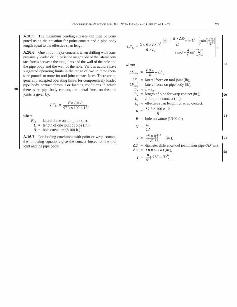
A.16.5 The maximum bending stresses can then be com-puted using the equation for point contact and a pipe bodylength equal to the effective span length.
A.16.6 One of our major concerns when drilling with com-pressively loaded drillpipe is the magnitude of the lateral con-tact forces between the tool joints and the wall of the hole andthe pipe body and the wall of the hole. Various authors havesuggested operating limits in the range of two to three thou-sand pounds or more for tool joint contact faces. There are nogenerally accepted operating limits for compressively loadedpipe body contact forces. For loading conditions in whichthere is no pipe body contact, the lateral force on the tooljoints is given by:
,
whereFTJ = lateral force on tool joint (lb),
L = length of one joint of pipe (in.),B = hole curvature (°/100 ft.).
A.16.7 For loading conditions with point or wrap contact,the following equations give the contact forces for the tooljoint and the pipe body:
,
where
LFpipe =
LFtj = lateral force on tool joint (lb),LFpipe = lateral force on pipe body (lb),
Lw = L – Le,Lw = length of pipe for wrap contact (in.),Le = L for point contact (in.),Le = effective span length for wrap contact,
R =
B = hole curvature (°/100 ft.),
U =
J = (in.),
∆D = diameter difference tool joint minus pipe OD (in.),∆D = TJOD – OD (in.),
I = .
LFTJF L× B×
57.3 100× 12×-------------------------------------=
98
LFTJ2 E× I× U2×
R Le×---------------------------------
1 4R ∆D×Le
2---------------------–
Usin 4U----sin2 U
2----
–
Usin 4U----sin2 U
2----
–
------------------------------------------------------------------------------=
F L×R
------------- LFtj–
00
57.3 100× 12×B
-------------------------------------98
Le
2J-----
E I×F
----------- 1 2⁄
98
03
π64------ OD4 ID4–( )
98
24 API RECOMMENDED PRACTICE 7G
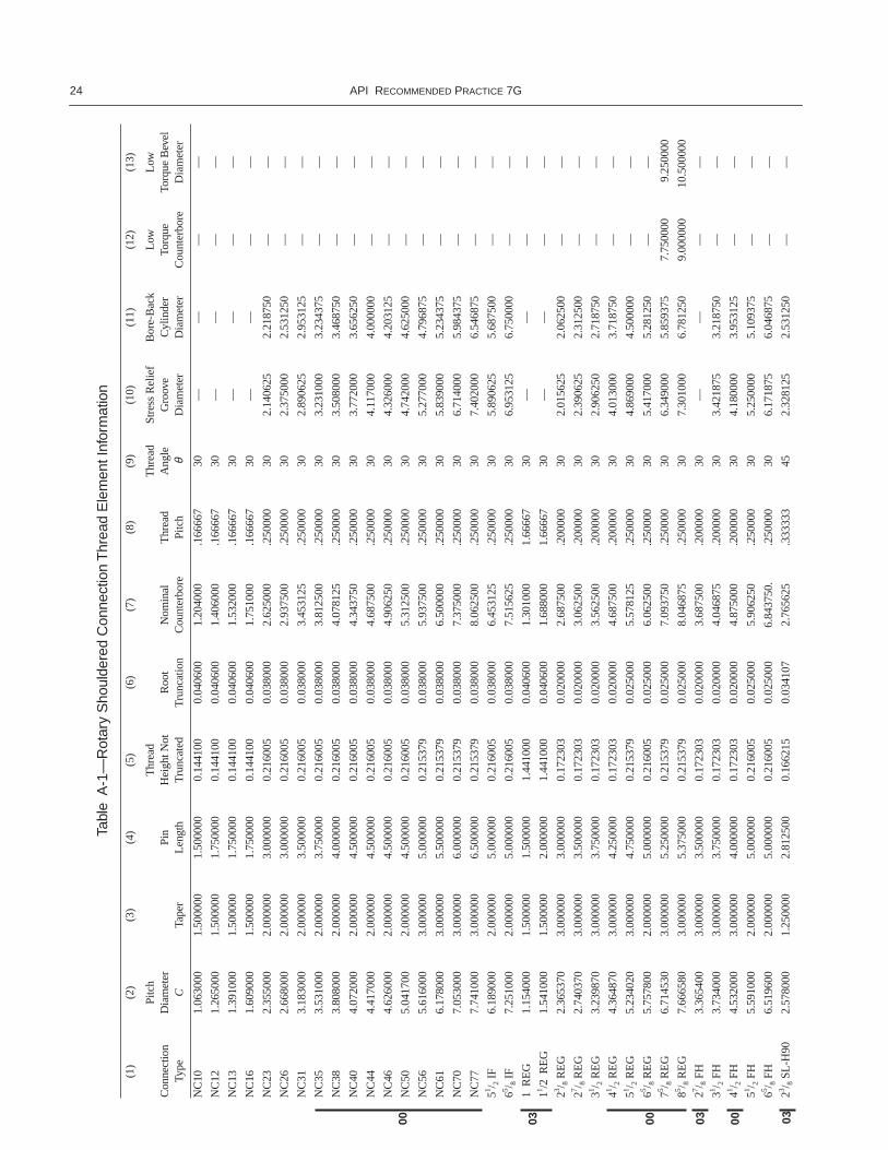
Tabl
eA
-1—
Rot
ary
Sho
ulde
red
Con
nect
ion
Thr
ead
Ele
men
t Inf
orm
atio
n
(1)
(2)
(3)
(4)
(5)
(6)
(7)
(8)
(9)
(10)
(11)
(12)
(13)
Con
nect
ion
Type
Pitc
hD
iam
eter
CTa
per
Pin
Len
gth
Thr
ead
Hei
ght N
ot
Tru
ncat
edR
oot
Tru
ncat
ion
Nom
inal
C
ount
erbo
reT
hrea
dPi
tch
Thr
ead
Ang
leθ
Stre
ss R
elie
f G
roov
e D
iam
eter
Bor
e-B
ack
Cyl
inde
r D
iam
eter
Low
Torq
ue
Cou
nter
bore
Low
Torq
ue B
evel
D
iam
eter
NC
101.
0630
001.
5000
001.
5000
000.
1441
000.
0406
001.
2040
00.1
6666
730
——
——
NC
121.
2650
001.
5000
001.
7500
000.
1441
000.
0406
001.
4060
00.1
6666
730
——
——
NC
131.
3910
001.
5000
001.
7500
000.
1441
000.
0406
001.
5320
00.1
6666
730
——
——
NC
161.
6090
001.
5000
001.
7500
000.
1441
000.
0406
001.
7510
00.1
6666
730
——
——
NC
232.
3550
002.
0000
003.
0000
000.
2160
050.
0380
002.
6250
00.2
5000
030
2.14
0625
2.21
8750
——
NC
262.
6680
002.
0000
003.
0000
000.
2160
050.
0380
002.
9375
00.2
5000
030
2.37
5000
2.53
1250
——
NC
313.
1830
002.
0000
003.
5000
000.
2160
050.
0380
003.
4531
25.2
5000
030
2.89
0625
2.95
3125
——
NC
353.
5310
002.
0000
003.
7500
000.
2160
050.
0380
003.
8125
00.2
5000
030
3.23
1000
3.23
4375
——
NC
383.
8080
002.
0000
004.
0000
000.
2160
050.
0380
004.
0781
25.2
5000
030
3.50
8000
3.46
8750
——
NC
404.
0720
002.
0000
004.
5000
000.
2160
050.
0380
004.
3437
50.2
5000
030
3.77
2000
3.65
6250
——
NC
444.
4170
002.
0000
004.
5000
000.
2160
050.
0380
004.
6875
00.2
5000
030
4.11
7000
4.00
0000
——
NC
464.
6260
002.
0000
004.
5000
000.
2160
050.
0380
004.
9062
50.2
5000
030
4.32
6000
4.20
3125
——
NC
505.
0417
002.
0000
004.
5000
000.
2160
050.
0380
005.
3125
00.2
5000
030
4.74
2000
4.62
5000
——
NC
565.
6160
003.
0000
005.
0000
000.
2153
790.
0380
005.
9375
00.2
5000
030
5.27
7000
4.79
6875
——
NC
616.
1780
003.
0000
005.
5000
000.
2153
790.
0380
006.
5000
00.2
5000
030
5.83
9000
5.23
4375
——
NC
707.
0530
003.
0000
006.
0000
000.
2153
790.
0380
007.
3750
00.2
5000
030
6.71
4000
5.98
4375
——
NC
777.
7410
003.
0000
006.
5000
000.
2153
790.
0380
008.
0625
00.2
5000
030
7.40
2000
6.54
6875
——
51 / 2 I
F6.
1890
002.
0000
005.
0000
000.
2160
050.
0380
006.
4531
25.2
5000
030
5.89
0625
5.68
7500
——
65 / 8 I
F7.
2510
002.
0000
005.
0000
000.
2160
050.
0380
007.
5156
25.2
5000
030
6.95
3125
6.75
0000
——
1 R
EG
1.15
4000
1.50
0000
1.50
0000
1.44
1000
0.04
0600
1.30
1000
1.66
667
30—
——
—
11 /2 R
EG
1.54
1000
1.50
0000
2.00
0000
1.44
1000
0.04
0600
1.68
8000
1.66
667
30—
——
—
23 / 8 R
EG
2.36
5370
3.00
0000
3.00
0000
0.17
2303
0.02
0000
2.68
7500
.200
000
302.
0156
252.
0625
00—
—
27 / 8 R
EG
2.74
0370
3.00
0000
3.50
0000
0.17
2303
0.02
0000
3.06
2500
.200
000
302.
3906
252.
3125
00—
—
31 / 2 R
EG
3.23
9870
3.00
0000
3.75
0000
0.17
2303
0.02
0000
3.56
2500
.200
000
302.
9062
502.
7187
50—
—
41 / 2 R
EG
4.36
4870
3.00
0000
4.25
0000
0.17
2303
0.02
0000
4.68
7500
.200
000
304.
0130
003.
7187
50—
—
51 / 2 R
EG
5.23
4020
3.00
0000
4.75
0000
0.21
5379
0.02
5000
5.57
8125
.250
000
304.
8690
004.
5000
00—
—
65 / 8 R
EG
5.75
7800
2.00
0000
5.00
0000
0.21
6005
0.02
5000
6.06
2500
.250
000
305.
4170
005.
2812
50—
—
75 / 8 R
EG
6.71
4530
3.00
0000
5.25
0000
0.21
5379
0.02
5000
7.09
3750
.250
000
306.
3490
005.
8593
757.
7500
00 9
.250
000
85 / 8 R
EG
7.66
6580
3.00
0000
5.37
5000
0.21
5379
0.02
5000
8.04
6875
.250
000
307.
3010
006.
7812
509.
0000
0010
.500
000
27 / 8 F
H3.
3654
003.
0000
003.
5000
000.
1723
030.
0200
003.
6875
00.2
0000
030
——
——
31 / 2 F
H3.
7340
003.
0000
003.
7500
000.
1723
030.
0200
004.
0468
75.2
0000
030
3.42
1875
3.21
8750
——
41 / 2 F
H4.
5320
003.
0000
004.
0000
000.
1723
030.
0200
004.
8750
00.2
0000
030
4.18
0000
3.95
3125
——
51 / 2 F
H5.
5910
002.
0000
005.
0000
000.
2160
050.
0250
005.
9062
50.2
5000
030
5.25
0000
5.10
9375
——
65 / 8 F
H6.
5196
002.
0000
005.
0000
000.
2160
050.
0250
006.
8437
50.
.250
000
306.
1718
756.
0468
75—
—
23 / 8 S
L-H
902.
5780
001.
2500
002.
8125
000.
1662
150.
0341
072.
7656
25.3
3333
345
2.32
8125
2.53
1250
——
00 03 00 0003 03
RECOMMENDED PRACTICE FOR DRILL STEM DESIGN AND OPERATING LIMITS 25
27 / 8 S
L-H
903.
0490
001.
2500
002.
9375
000.
1662
150.
0341
073.
2343
75.3
3333
345
2.67
1875
2.98
4375
——
31 / 2 S
L-H
903.
6880
001.
2500
003.
1875
000.
1662
150.
0341
073.
8750
00.3
3333
345
3.31
2500
3.59
3750
——
31 / 2 H
-90
3.92
9860
2.00
0000
4.00
0000
0.14
1865
0.01
7042
4.18
7500
.285
710
453.
6562
503.
5625
00—
—
4 H
-90
4.30
3600
2.00
0000
4.25
0000
0.14
1865
0.01
7042
4.56
2500
.285
710
454.
0312
503.
8750
00—
—
41 / 2 H
-90
4.63
7600
2.00
0000
4.50
0000
0.14
1865
0.01
7042
4.89
0625
.285
710
454.
3593
754.
1875
00—
—
5 H
-90
4.90
8100
2.00
0000
4.75
0000
0.14
1865
0.01
7042
5.17
1875
.285
710
454.
6250
004.
4062
50—
—
51 / 2 H
-90
5.17
8600
2.00
0000
4.75
0000
0.14
1865
0.01
7042
5.43
7500
.285
710
454.
9062
504.
6875
00—
—
65 / 8 H
-90
5.80
3600
2.00
0000
5.00
0000
0.14
1865
0.01
7042
6.06
2500
.285
710
455.
5312
505.
2656
25—
—
7 H
-90
6.25
2300
3.00
0000
5.50
0000
0.14
0625
0.01
6733
6.56
2500
.285
710
456.
0312
505.
2656
257.
1250
008.
2500
00
75 / 8 H
-90
7.14
1100
3.00
0000
6.12
5000
0.14
0625
0.01
6733
7.45
3125
.285
710
456.
9062
506.
0000
008.
0000
009.
2500
00
85 / 8 H
-90
8.01
6100
3.00
0000
6.62
5000
0.14
0625
0.01
6733
8.32
8125
.285
710
457.
7812
506.
7500
009.
3750
0010
.500
000
23 / 8 P
AC
2.20
3000
1.50
0000
2.37
5000
0.21
6224
0.05
7948
2.40
6250
.250
000
301.
9843
752.
1718
75—
—
27 / 8 P
AC
2.36
9000
1.50
0000
2.37
5000
0.21
6224
0.05
7948
2.57
8125
.250
000
302.
1562
502.
3437
50—
—
31 / 2 P
AC
2.88
4000
1.50
0000
3.25
0000
0.21
6224
0.05
7948
3.10
9375
.250
000
30—
——
—
23 / 8 S
H2.
2300
002.
0000
002.
8750
000.
2160
050.
0380
002.
5000
00.2
5000
030
1.93
7500
2.09
3750
——
27 / 8 S
H2.
6680
002.
0000
003.
0000
000.
2160
050.
0380
002.
9375
00.2
5000
030
2.37
5000
2.53
1250
——
31 / 2 S
H3.
1830
002.
0000
003.
5000
000.
2160
050.
0380
003.
4531
25.2
5000
030
2.89
0625
2.95
3125
——
4 SH
3.60
4000
2.00
0000
3.50
0000
0.21
6005
0.03
8000
3.87
5000
.250
000
303.
3125
003.
3750
00—
—
41 / 2 S
H3.
8080
002.
0000
004.
0000
000.
2160
050.
0380
004.
0781
25.2
5000
030
3.50
8000
3.46
8750
——
27 / 8 X
H3.
1190
002.
0000
004.
0000
000.
2160
050.
0380
003.
3593
75.2
5000
030
2.82
8125
2.78
1250
——
31 / 2 X
H3.
6040
002.
0000
003.
5000
000.
2160
050.
0380
003.
8750
00.2
5000
030
3.31
2500
3.37
5000
——
5 X
H5.
0417
002.
0000
004.
5000
000.
2160
050.
0380
005.
3125
00.2
5000
030
4.74
2000
4.62
5000
——
23 / 8 O
H S
W2.
5880
001.
5000
002.
3750
000.
2162
240.
0579
482.
7968
75.2
5000
030
——
——
23 / 8 O
H L
W2.
5880
001.
5000
002.
3750
000.
2162
240.
0579
482.
7968
75.2
5000
030
——
——
27 / 8 O
H S
W2.
9840
001.
5000
002.
8750
000.
2162
240.
0579
483.
2031
25.2
5000
030
——
——
27 / 8 O
H L
W2.
9840
001.
5000
002.
5000
000.
2162
240.
0579
483.
2031
25.2
5000
030
——
——
31 / 2 O
H S
W3.
7280
001.
5000
003.
2500
000.
2162
240.
0579
483.
9531
25.2
5000
030
——
——
31 / 2 O
H L
W3.
7280
001.
5000
003.
2500
000.
2162
240.
0579
483.
9531
25.2
5000
030
——
——
4 O
H S
W4.
4160
001.
5000
004.
0000
000.
2162
240.
0579
484.
6406
25.2
5000
030
——
——
4 O
H L
W4.
4160
001.
5000
003.
5000
000.
2162
240.
0579
484.
6406
25.2
5000
030
——
——
41 / 2 O
H S
W4.
7520
001.
5000
003.
7500
000.
2162
240.
0579
484.
9531
25.2
5000
030
——
——
41 / 2 O
H L
W4.
7520
001.
5000
003.
7500
000.
2162
240.
0579
484.
9531
25.2
5000
030
——
——
23 / 8 W
O2.
6050
002.
0000
002.
3750
000.
2160
050.
0380
002.
8593
75.2
5000
030
——
——
27 / 8 W
O3.
1210
002.
0000
003.
0000
000.
2160
050.
0380
003.
3750
00.2
5000
030
——
——
31 / 2 W
O3.
8080
002.
0000
003.
5000
000.
2160
050.
0380
004.
0781
25.2
5000
030
——
——
4 W
O4.
6260
002.
0000
004.
5000
000.
2160
050.
0380
004.
9062
50.2
5000
030
——
——
41 / 2 W
O5.
0417
002.
0000
004.
5000
000.
2160
050.
0380
005.
3125
00.2
5000
030
——
——
Tabl
eA
-1—
Rot
ary
Sho
ulde
red
Con
nect
ion
Thr
ead
Ele
men
t Inf
orm
atio
n
(1)
(2)
(3)
(4)
(5)
(6)
(7)
(8)
(9)
(10)
(11)
(12)
(13)
Con
nect
ion
Type
Pitc
hD
iam
eter
CTa
per
Pin
Len
gth
Thr
ead
Hei
ght N
ot
Tru
ncat
edR
oot
Tru
ncat
ion
Nom
inal
C
ount
erbo
reT
hrea
dPi
tch
Thr
ead
Ang
leθ
Stre
ss R
elie
f G
roov
e D
iam
eter
Bor
e-B
ack
Cyl
inde
r D
iam
eter
Low
Torq
ue
Cou
nter
bore
Low
Torq
ue B
evel
D
iam
eter
03 0000


11/03

Additional copies available through Global Engineering Documents at (800) 854-7179 or (303) 397-7956
Information about API Publications, Programs and Services isavailable on the World Wide Web at: http://www.api.org
Product No. G07GA1
Recommended


![Avr3808e2a Addendum Im 007[1]](https://img.pdfslide.tips/doc/110x75/55cf9743550346d033909f3c/avr3808e2a-addendum-im-0071.jpg)