CALCULATION OF TEMPORALY PROTECTION STRUCTURE
1
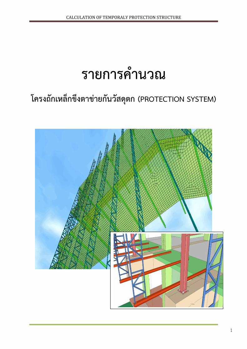
รายการค านวณ โครงถกเหลกขงตาขายกนวสดตก (PROTECTION SYSTEM)
CALCULATION OF TEMPORALY PROTECTION STRUCTURE
2
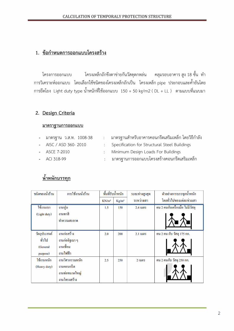
1. ขอก าหนดการออกแบบโครงสราง
โครงการออกแบบ โครงเหลกถกขงตาขายกนวสดตกหลน คลมรอบอาคาร สง 18 ชน ท าการวเคราะหออกแบบ โดยเลอกใชชนดของโครงเหลกถกเปน โครงเหลก pipe ประกอบและค ายนโดยการยดโยง Light duty type น าหนกทใชออกแบบ 150 + 50 kg/m2 ( DL + LL ) ตามแบบทแนบมา
2. Design Criteria
มาตราฐานการออกแบบ
- มาตรฐาน ว.ส.ท. 1008-38 : มาตรฐานส าหรบอาคารคอนกรตเสรมเหลก โดยวธก าลง - AISC / ASD 360- 2010 : Specification for Structural Steel Buildings - ASCE 7-2010 : Minimum Design Loads For Buildings - ACI 318-99 : มาตรฐานการออกแบบโครงสรางคอนกรตเสรมเหลก
น ำหนกบรรทก

CALCULATION OF TEMPORALY PROTECTION STRUCTURE
3
แรงลมกระท ากบโครงสราง
แรงลมทใชในการค านวณออกแบบ ตาม พ.ร.บ. ใหใชดงตอไปน
อาคารทสงไมเกน 10 ม. หนวยแรงลมอยางนอย 50 kg/m2
อาคารทมชวงความสง 10 – 20 ม. หนวยแรงลมอยางนอย 80 kg/m2
อาคารทมชวงความสง 20 – 40 ม. หนวยแรงลมอยางนอย 120 kg/m2
อาคารทสงเกน 40 ม. หนวยแรงลมอยางนอย 160 kg/m2
หรอ คาทมากกวาจากการค านวณแบบละเอยดตามมาตรฐาน E.I.T
“ มาตรฐานการค านวณแรงลม ส าหรบการออกแบบอาคาร “
The Engineering Institute of Thailand Under H.M. The King’s Patronage
แผนทความเรวลมอางอง
พนทกอสรางอยท มหาวทยาลยหอการคา กทม.
จดเปน กลม 1 V50 = 25 m/s
พนทอยชานเมอง Class : C
จากโปรแกรม FEM MIDAS GEN ทใชเปน
มาตรฐาน ASCE จงตองแปลงคาความเรวลม
อางองใหเทากบ มยผ. เนองดวย ASCE เกบ
คาเฉลยท 3 วนาท แตประเทศไทยเกบท 1 ชวโมง
V3 / V3600 = 1.52
25*1.52 = 38 m/s
38*2.23 = 85 Mph
CALCULATION OF TEMPORALY PROTECTION STRUCTURE
4
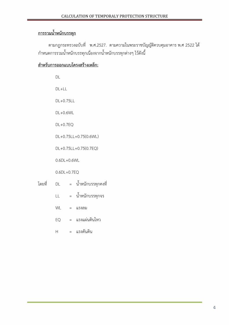
การรวมน าหนกบรรทก
ตามกฎกระทรวงฉบบท .ศ.พ 2527 ตามความในพระราชบญญตควบคมอาคาร พ.ศ . 2522 ไดก าหนดการรวมน าหนกบรรทกเนองจากน าหนกบรรทกตางๆ ไวดงน
ส าหรบการออกแบบโครงสรางเหลก:
DL
DL+LL
DL+0.75LL
DL+0.6WL
DL+0.7EQ
DL+0.75LL+0.75(0.6WL)
DL+0.75LL+0.75(0.7EQ)
0.6DL+0.6WL
0.6DL+0.7EQ
โดยท DL = น าหนกบรรทกคงท
LL = น าหนกบรรทกจร
WL = แรงลม
EQ = แรงแผนดนไหว
H = แรงดนดน

CALCULATION OF TEMPORALY PROTECTION STRUCTURE
5
คอนกรต
ก าลงคอนกรตจะขนอยหรอยดตดกบก าลงของตวอยางทดสอบลกทรงกระบอก ชนดคอนกรตแบงตามการใชงานทวไปของแตประเภทตามตอไปน
- ฐานราก เสา คาน และพน 240 กก/ซม2 - ส าหรบคอนกรตปรบระดบ และคอนกรตหยาบ 150 กก/ซม2 - ส าหรบคอนกรตปรบระดบเพอรองรบโครงสรางเหลก 180 กก/ซม2 - โครงสรางอยางอน 180 กก/ซม2 คณสมบตของปนซเมนตตองใชปนซเมนตปอรตแลนด ประเภท หนง
เหลกเสรม
เหลกเสนกลมตองตรงตามมาตราฐาน มอก 24-2527 ชนด SR 24 โดยมก าลงครากต าสดเทากบ 2,400 กก/ซม2
เหลกเสนขอออยส าหรบฐานราก เสา คาน และพนตองตรงตามมาตราฐาน มอก 24-2527 ชนด SD 40 โดยมก าลงครากต าสดเทากบ 4,000 กก/ซม2
เหลกรปพรรณ
เหลกรดรอนตองตรงตามมาตราฐาน มอก 1227-2539 ชนด SM 400 โดยมก าลงครากต าสดเทากบ 245 MPa ( 2,498 กก/ซม2 )
Structural Steel
In general, JIS G3106 GRADE SM400A (SM41A) shall be used. However, the following structural steel material may be used: Steel certified to JIS G3101 GRADE SS400 or SS41 is also acceptable if the chemical Composition is within the requirements of JIS 3106 Table 2.2.ASTM A36 Square and rectangular hollow sections for structural use shall conform to JIS G3466 STKR 400.Structural steel pipe shall conform to JIS G3444 STK 400. Built up section utilizing plate shall conform to ASTM A36 or JIS G 3106 Grade SM400A (SM41A). All structural steel shall have a minimum tensile strength of 2,400 kg/cm2
CALCULATION OF TEMPORALY PROTECTION STRUCTURE
6
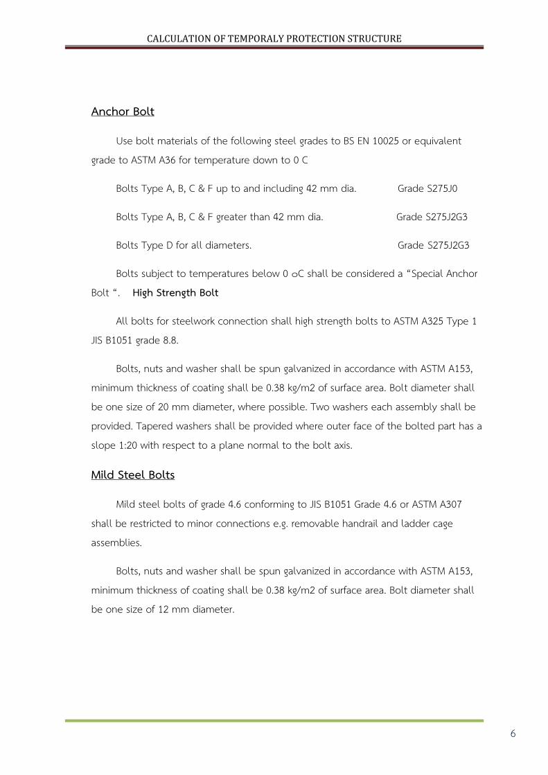
Anchor Bolt
Use bolt materials of the following steel grades to BS EN 10025 or equivalent grade to ASTM A36 for temperature down to 0 C
Bolts Type A, B, C & F up to and including 42 mm dia. Grade S275J0
Bolts Type A, B, C & F greater than 42 mm dia. Grade S275J2G3
Bolts Type D for all diameters. Grade S275J2G3
Bolts subject to temperatures below 0 ๐C shall be considered a “Special Anchor Bolt “. High Strength Bolt
All bolts for steelwork connection shall high strength bolts to ASTM A325 Type 1 JIS B1051 grade 8.8.
Bolts, nuts and washer shall be spun galvanized in accordance with ASTM A153, minimum thickness of coating shall be 0.38 kg/m2 of surface area. Bolt diameter shall be one size of 20 mm diameter, where possible. Two washers each assembly shall be provided. Tapered washers shall be provided where outer face of the bolted part has a slope 1:20 with respect to a plane normal to the bolt axis.
Mild Steel Bolts
Mild steel bolts of grade 4.6 conforming to JIS B1051 Grade 4.6 or ASTM A307 shall be restricted to minor connections e.g. removable handrail and ladder cage assemblies.
Bolts, nuts and washer shall be spun galvanized in accordance with ASTM A153, minimum thickness of coating shall be 0.38 kg/m2 of surface area. Bolt diameter shall be one size of 12 mm diameter.
CALCULATION OF TEMPORALY PROTECTION STRUCTURE
7
Welding Electrode
Electrodes for manual welding shall comply with AWS Code A5.1 Covered Carbon Steel Arc-Welding Electrodes, E70 series.
Safety Factors for Stability
Limit of Deflections:
The following criteria for deflection shall be adhered to for normal operation and test load combinations.
Beams supporting floors : max. 1/360 th of the span
Beams supporting equipment : max. 1/500 th of the span
Cantilever beams : max. 1/180 th of the overhang
Maximum total horizontal displacement of portal frames shall not exceed 1/200 th of the height.
CALCULATION OF TEMPORALY PROTECTION STRUCTURE
8
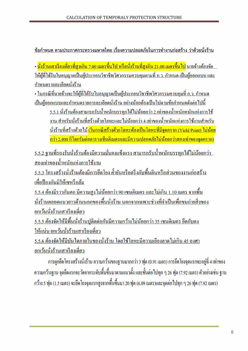
ขอก าหนด ตามประกาศกระทรวงมหาดไทย เรองความปลอดภยในการท างานกอสราง วาดวยนงราน
CALCULATION OF TEMPORALY PROTECTION STRUCTURE
9
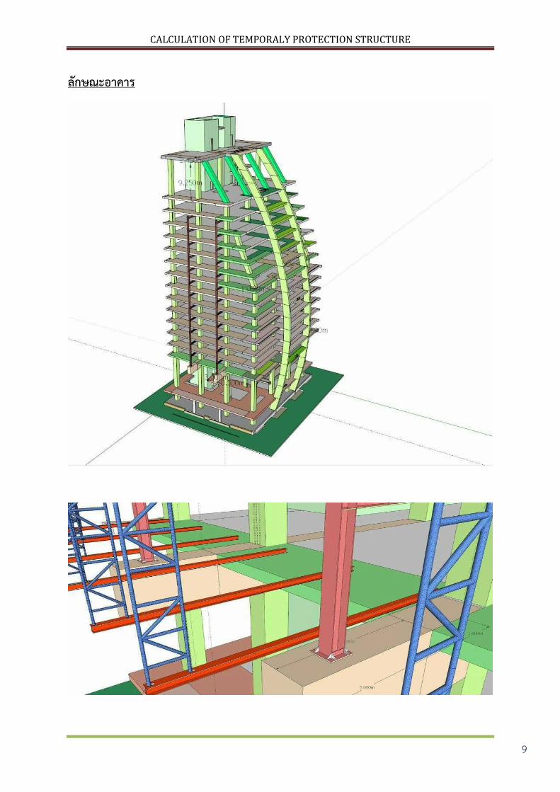
ลกษณะอาคาร
CALCULATION OF TEMPORALY PROTECTION STRUCTURE
10
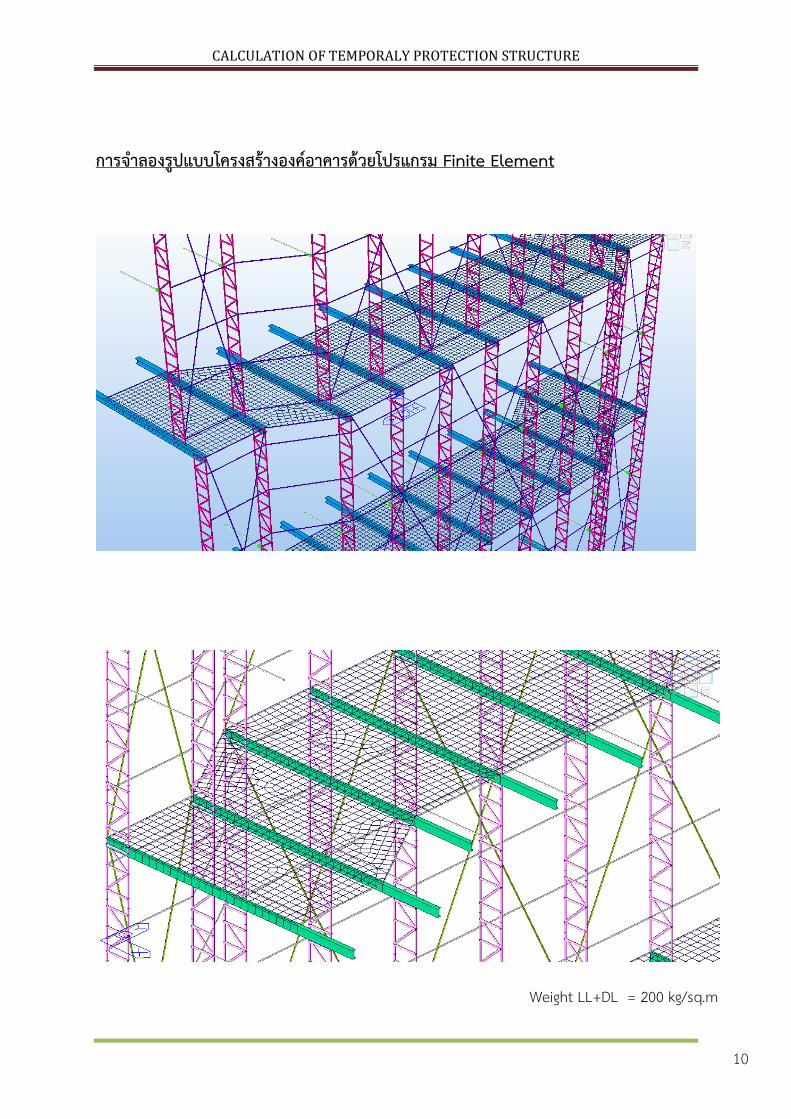
การจ าลองรปแบบโครงสรางองคอาคารดวยโปรแกรม Finite Element
Weight LL+DL = 200 kg/sq.m

CALCULATION OF TEMPORALY PROTECTION STRUCTURE
11
แสดงแรงลมทกระท าตอชนสวนตามระดบความสง
CALCULATION OF TEMPORALY PROTECTION STRUCTURE
12
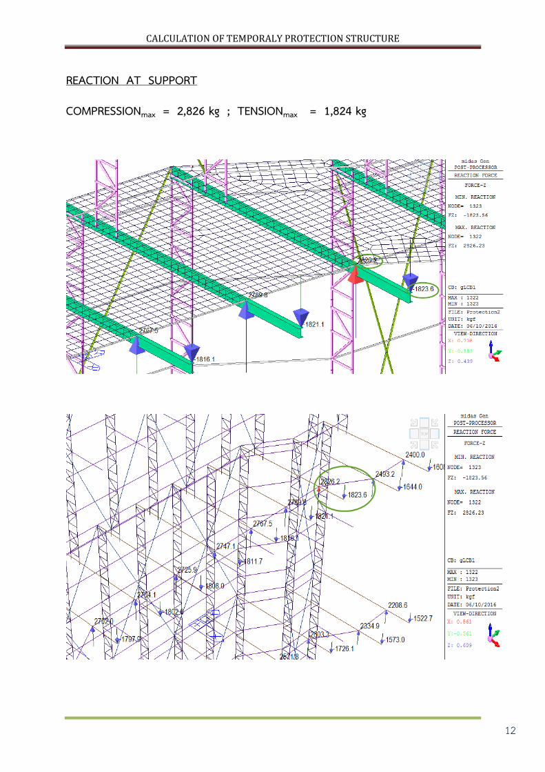
REACTION AT SUPPORT
COMPRESSIONmax = 2,826 kg ; TENSIONmax = 1,824 kg
CALCULATION OF TEMPORALY PROTECTION STRUCTURE
13
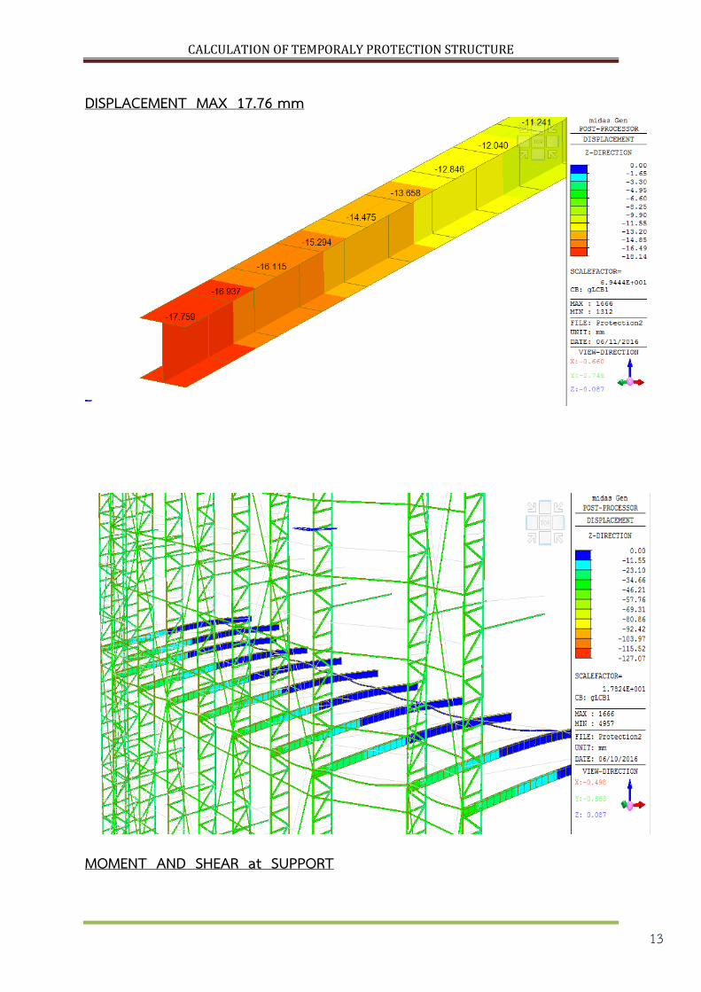
DISPLACEMENT MAX 17.76 mm
MOMENT AND SHEAR at SUPPORT
CALCULATION OF TEMPORALY PROTECTION STRUCTURE
14
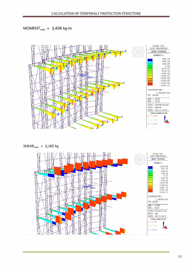
MOMENTmax = 2,438 kg-m
SHEARmax = 2,185 kg

CALCULATION OF TEMPORALY PROTECTION STRUCTURE
15
สรปผลการออกแบบ :
TEMPORARY PROTECTION STRUCTURE
CALCULATION OF TEMPORALY PROTECTION STRUCTURE
16
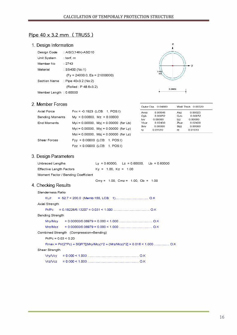
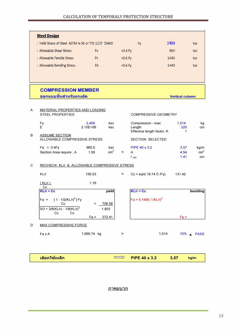
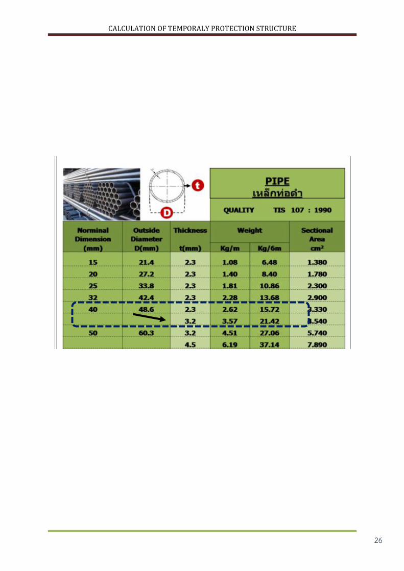
Pipe 40 x 3.2 mm ( TRUSS )
CALCULATION OF TEMPORALY PROTECTION STRUCTURE
17
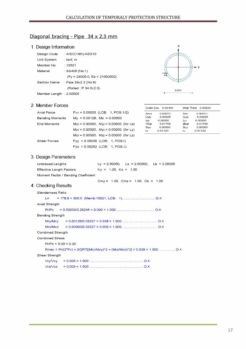
Diagonal bracing - Pipe 34 x 2.3 mm
CALCULATION OF TEMPORALY PROTECTION STRUCTURE
18
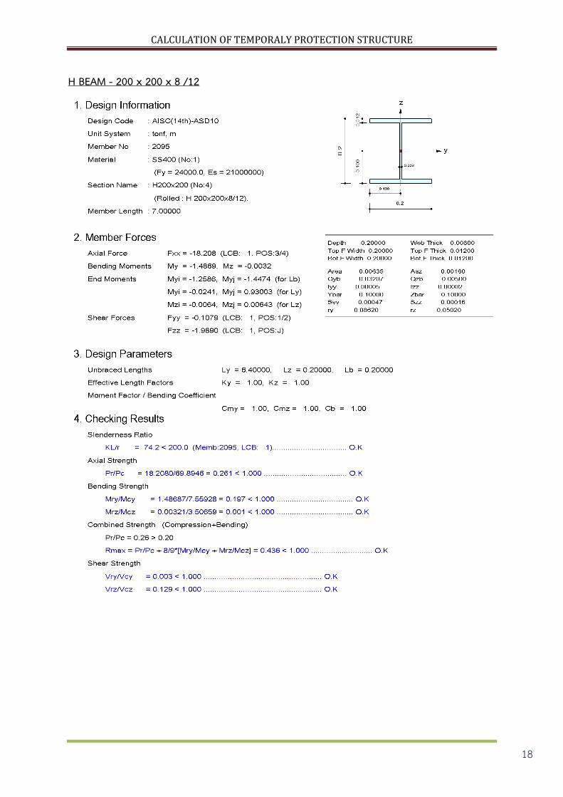
H BEAM - 200 x 200 x 8 /12
CALCULATION OF TEMPORALY PROTECTION STRUCTURE
19
ภาคผนวก
CALCULATION OF TEMPORALY PROTECTION STRUCTURE
20
CALCULATION OF TEMPORALY PROTECTION STRUCTURE
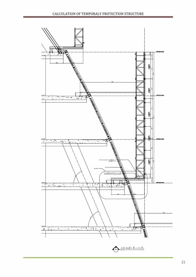
21

CALCULATION OF TEMPORALY PROTECTION STRUCTURE
22
CALCULATION OF TEMPORALY PROTECTION STRUCTURE
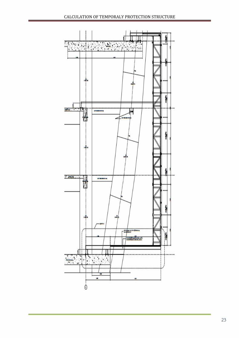
23

CALCULATION OF TEMPORALY PROTECTION STRUCTURE
24
CALCULATION OF TEMPORALY PROTECTION STRUCTURE
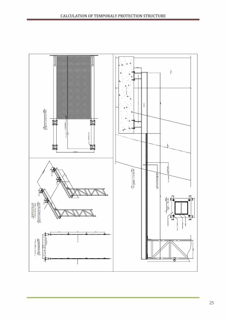
25
CALCULATION OF TEMPORALY PROTECTION STRUCTURE
26
CALCULATION OF TEMPORALY PROTECTION STRUCTURE
27
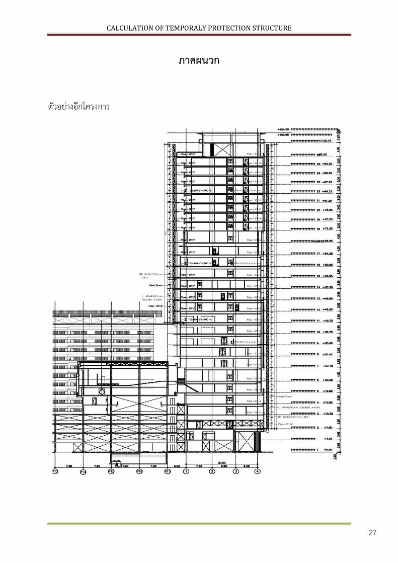
ภาคผนวก
ตวอยางอกโครงการ

CALCULATION OF TEMPORALY PROTECTION STRUCTURE
28
CALCULATION OF TEMPORALY PROTECTION STRUCTURE
29

CALCULATION OF TEMPORALY PROTECTION STRUCTURE
30
การ MODEL ในโปรแกรม STAAD Pro.
พจารณาแรงลม
CALCULATION OF TEMPORALY PROTECTION STRUCTURE
31
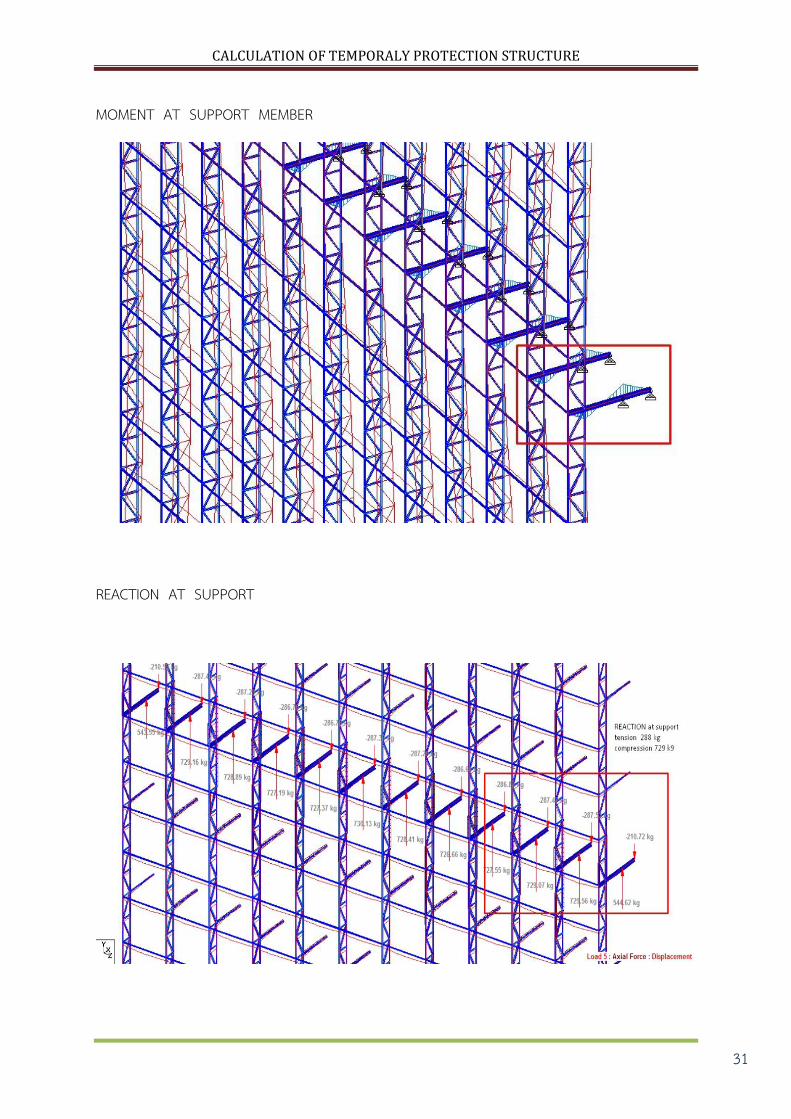
MOMENT AT SUPPORT MEMBER
REACTION AT SUPPORT

CALCULATION OF TEMPORALY PROTECTION STRUCTURE
32

CALCULATION OF TEMPORALY PROTECTION STRUCTURE
33
Recommended