
Core Builder Tool Change Sequence ------------------------------------------------------------------------------------
Core-builder Tool-change Sequence
1 Bring Tamper Assembly to a comfortable level for working.
2 Change Tamper plate 3 Move PFC Hold down to correct position.
4 Home Tamper Plate. 5 Bring Core Compress assembly up to Hold position. + x 3
6 Activate Tooling clamps on Screen.
7 Remove Compress Tooling. 8 Deactivate Tooling Clamps.
9 Take Compress Assembly to 0 position. – x 1 10 Replace or Change Build Table.
11 Bring Compress Assembly to Hold Position. + x 1 12 Activate Tooling Clamps.
13 Fit new Compress Tooling.
14 Deactivate Tooling Clamps. 15 Take Compress Assembly home.
16 Change Header Tooling or Header Inserts. 17 Change Header Bolster Spacers.
18 Lift Locator Elevators.
19 Change Locator Tooling or Inserts. 20 Home Locators.
21 Remove Transport Carriage Blades. X3 22 Remove Pivoting Fin Roof.
23 Move Retard and Compress Guide carefully out of the way 24 Remove Scroll Plate.
25 Fit new Scroll Plate, physically pushing L.H. Stack into position.
26 Fit new Pivoting Roof. 27 Fit new Transport Carriage Blades. X3
28 Carefully replace Retard and Compress Guide in correct position. 29 CHANGE PRODUCT CODE NUMBER
30 Fill Tube Stacks.
31 Reset Machine

Fin Mill Tool-Change ------------------------------------------------------------------------------------
Fin Mill Tool-change
1 Remove Coils and Strip from Throughout Fin Mill.
2 Remove De-coiler Spacers and replace with new size.
3 Remove Back-Tension Guide Assembly and replace with new size. 4 Remove Tunnel complete. 5 Lock clamps.
5 Lift Scroll and remove. Replace with new size. 6 Remove Fin Arrester and replace with new size.
7 Remove Scroll Guides and replace with new. 8 Remove Gathering Roll Cassette onto Special purpose Trolley
9 Remove Form Roll Cassette onto Special Purpose Trolley
10 Fit new Gathering Roll Cassette. 11 Fit new Form Roll Cassette.
12 Fit New Tunnel complete. 13 Set Dancing arm guides to new positions.
14 Set Pack-up and Pull-out Rolls to new position.
15 Set Fin to correct height and length.
16 PRODUCT CODE SHOULD HAVE BEEN CHANGED DURING CORE-BUILDER TOOL-CHANGE. If only Fin Mill is being changed, select new product code.
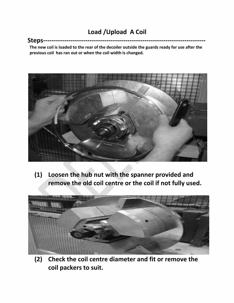
Load /Upload A Coil Steps----------------------------------------------------------------------------- The new coil is loaded to the rear of the decoiler outside the guards ready for use after the previous coil has ran out or when the coil width is changed.
(1) Loosen the hub nut with the spanner provided and remove the old coil centre or the coil if not fully used.
(2) Check the coil centre diameter and fit or remove the
coil packers to suit.
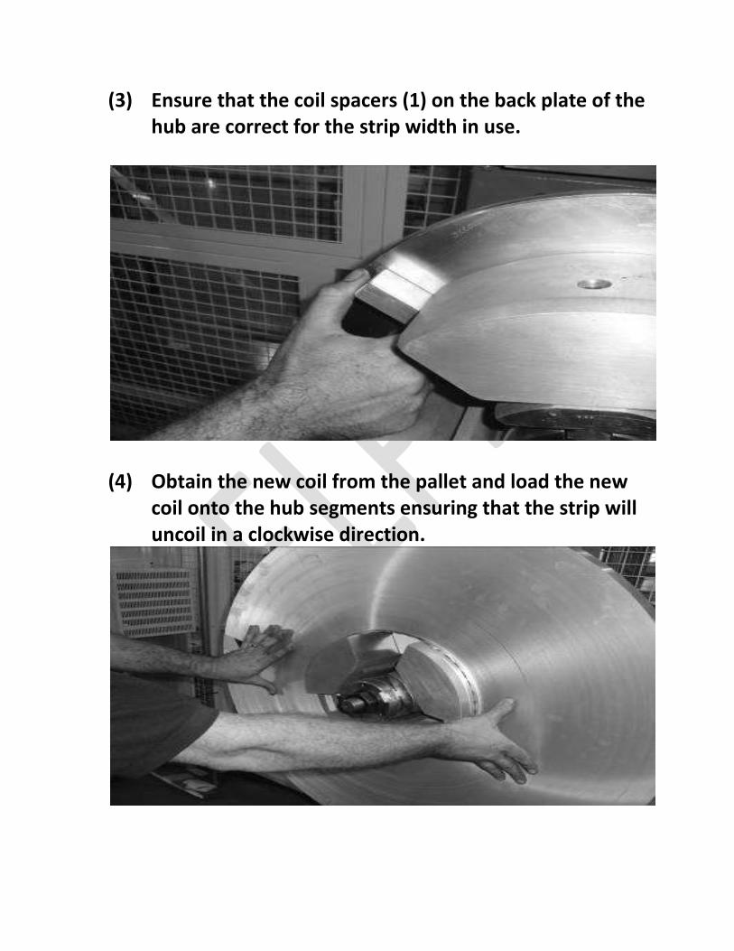
(3) Ensure that the coil spacers (1) on the back plate of the hub are correct for the strip width in use.
(4) Obtain the new coil from the pallet and load the new coil onto the hub segments ensuring that the strip will uncoil in a clockwise direction.
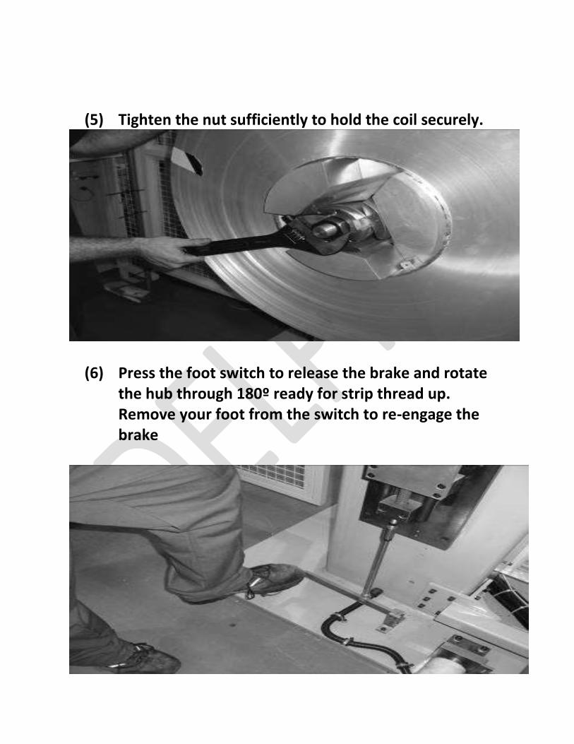
(5) Tighten the nut sufficiently to hold the coil securely.
(6) Press the foot switch to release the brake and rotate the hub through 180º ready for strip thread up. Remove your foot from the switch to re-engage the brake
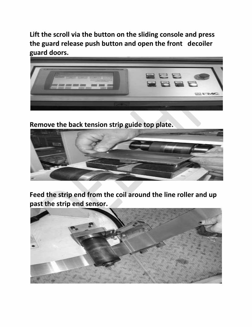
Lift the scroll via the button on the sliding console and press the guard release push button and open the front decoiler guard doors.
Remove the back tension strip guide top plate.
Feed the strip end from the coil around the line roller and up past the strip end sensor.
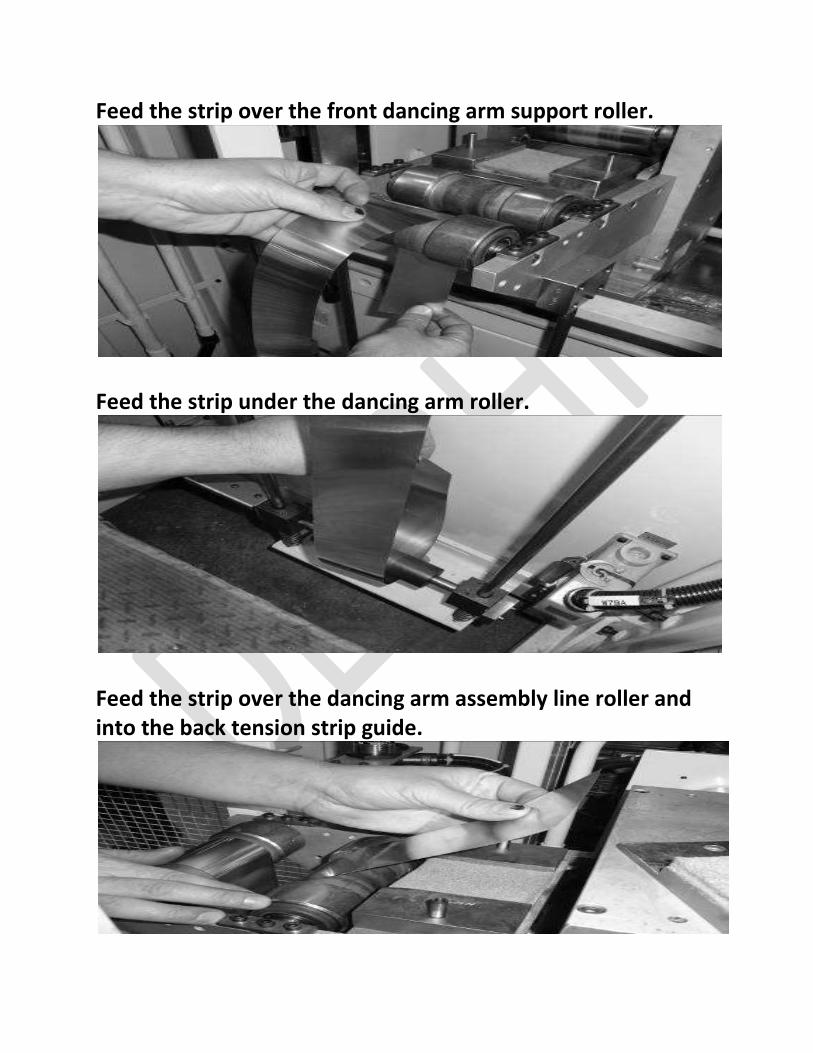
Feed the strip over the front dancing arm support roller.
Feed the strip under the dancing arm roller.
Feed the strip over the dancing arm assembly line roller and into the back tension strip guide.
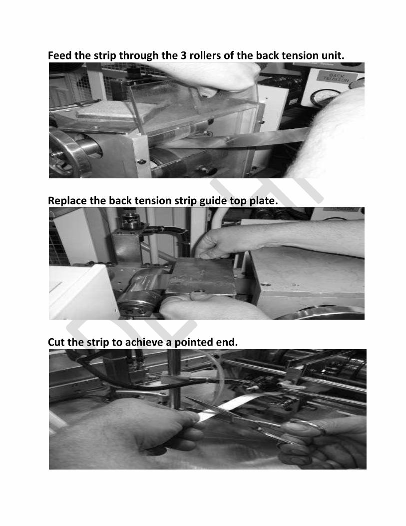
Feed the strip through the 3 rollers of the back tension unit.
Replace the back tension strip guide top plate.
Cut the strip to achieve a pointed end.
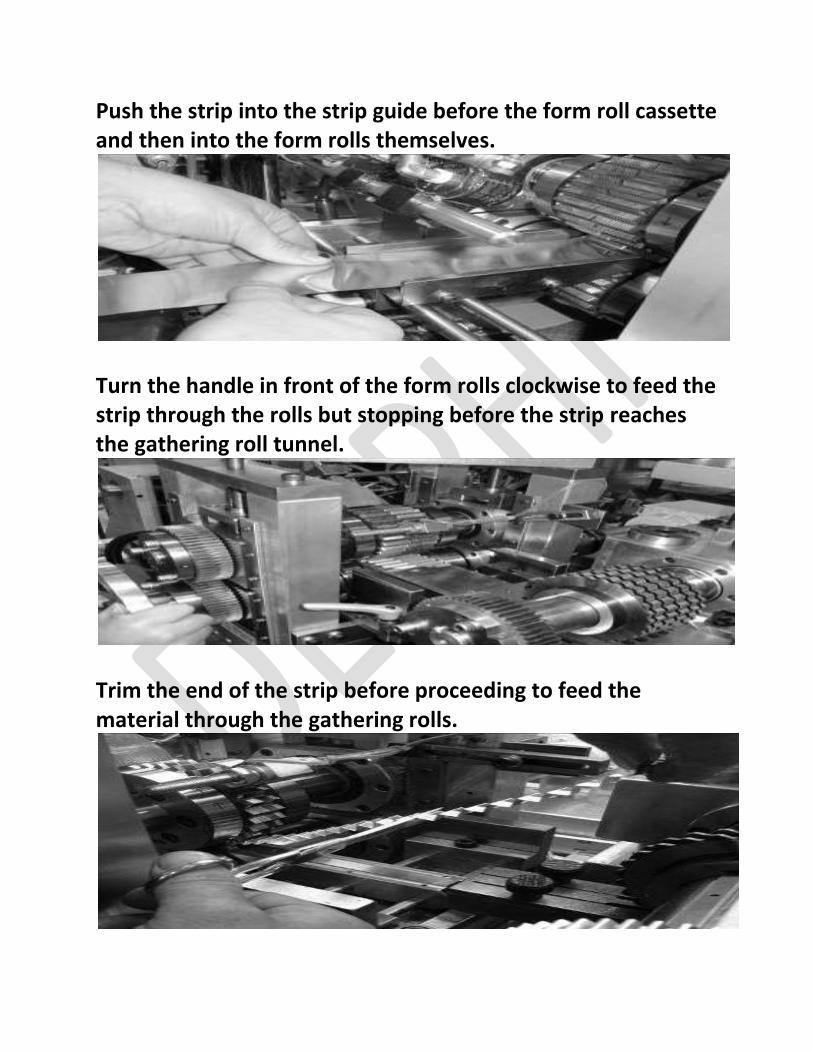
Push the strip into the strip guide before the form roll cassette and then into the form rolls themselves.
Turn the handle in front of the form rolls clockwise to feed the strip through the rolls but stopping before the strip reaches the gathering roll tunnel.
Trim the end of the strip before proceeding to feed the material through the gathering rolls.
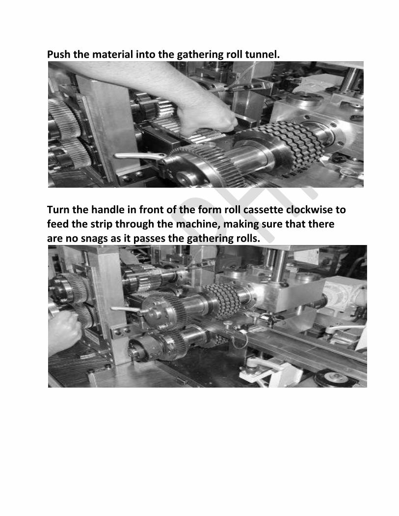
Push the material into the gathering roll tunnel.
Turn the handle in front of the form roll cassette clockwise to feed the strip through the machine, making sure that there are no snags as it passes the gathering rolls.
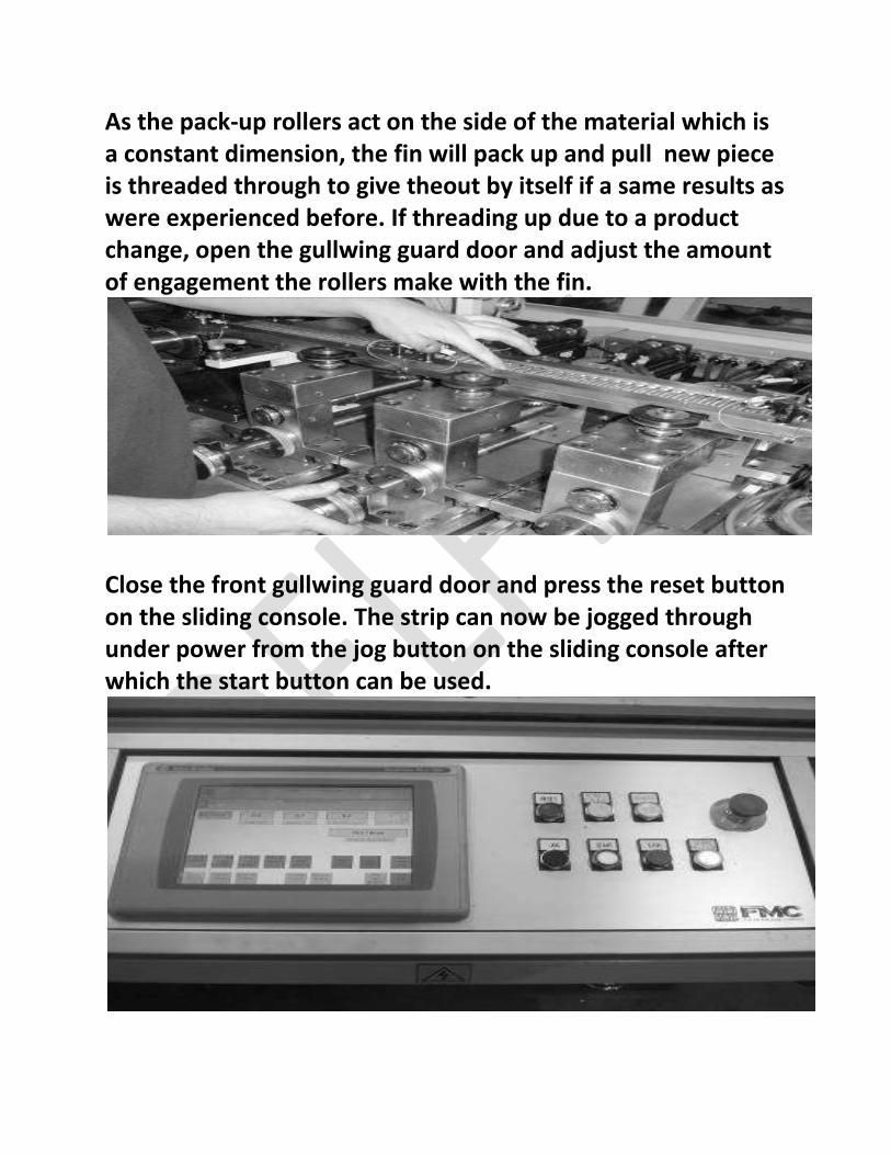
As the pack-up rollers act on the side of the material which is a constant dimension, the fin will pack up and pull new piece is threaded through to give theout by itself if a same results as were experienced before. If threading up due to a product change, open the gullwing guard door and adjust the amount of engagement the rollers make with the fin.
Close the front gullwing guard door and press the reset button on the sliding console. The strip can now be jogged through under power from the jog button on the sliding console after which the start button can be used.
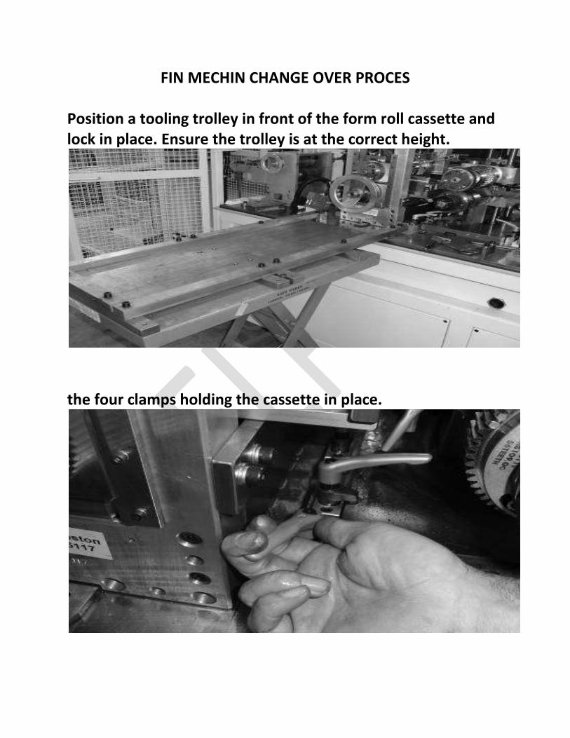
FIN MECHIN CHANGE OVER PROCES Position a tooling trolley in front of the form roll cassette and lock in place. Ensure the trolley is at the correct height.
the four clamps holding the cassette in place.
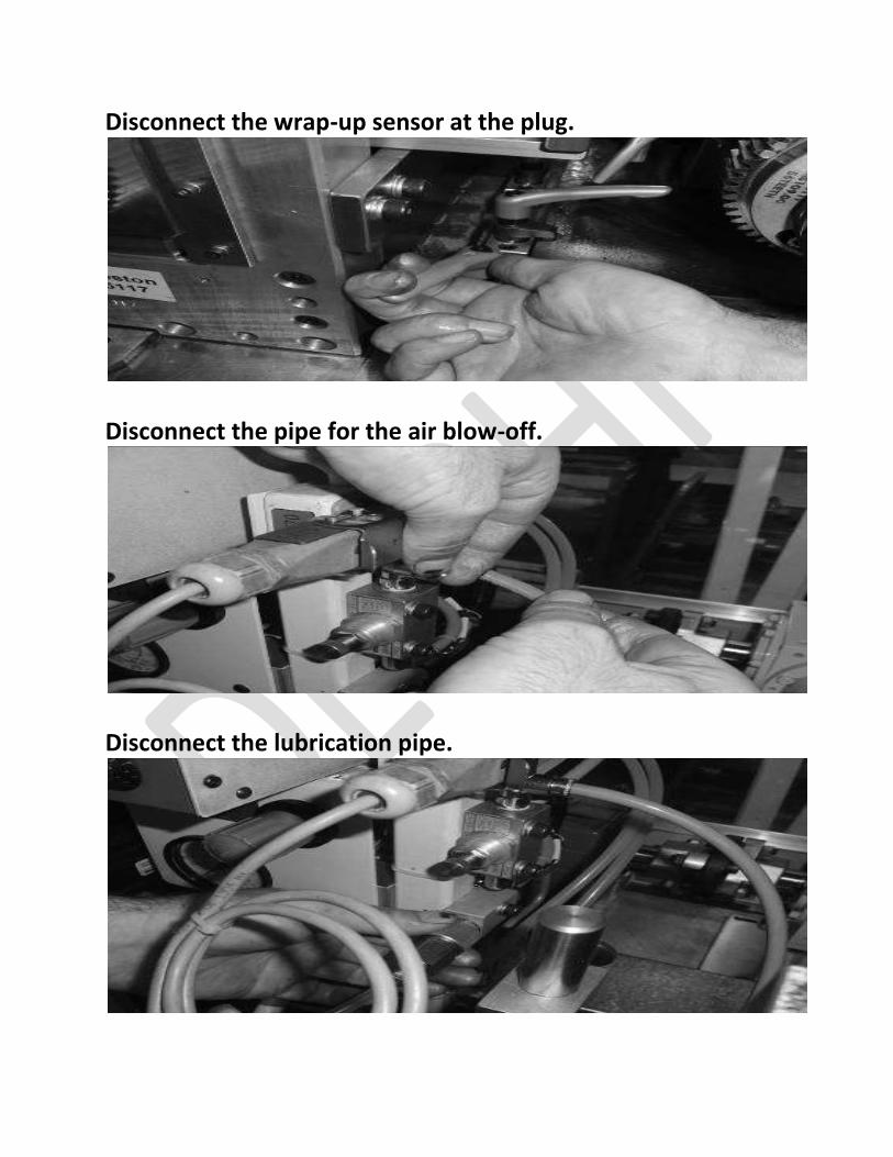
Disconnect the wrap-up sensor at the plug.
Disconnect the pipe for the air blow-off.
Disconnect the lubrication pipe.
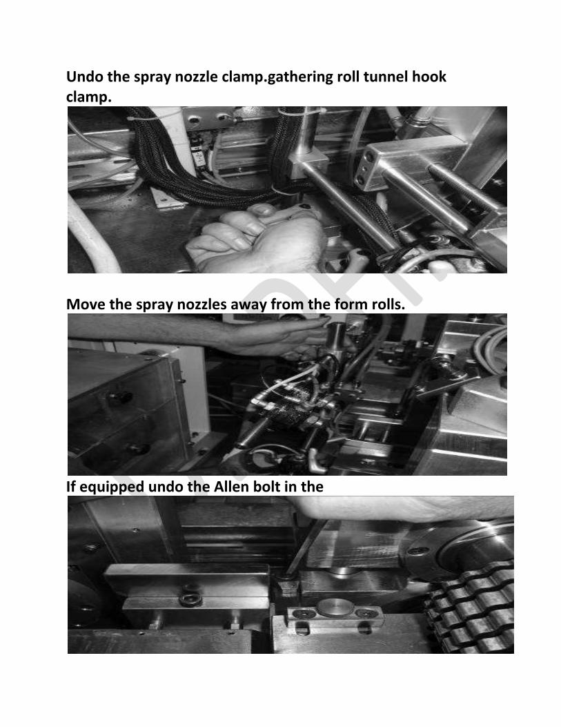
Undo the spray nozzle clamp.gathering roll tunnel hook clamp.
Move the spray nozzles away from the form rolls.
If equipped undo the Allen bolt in the
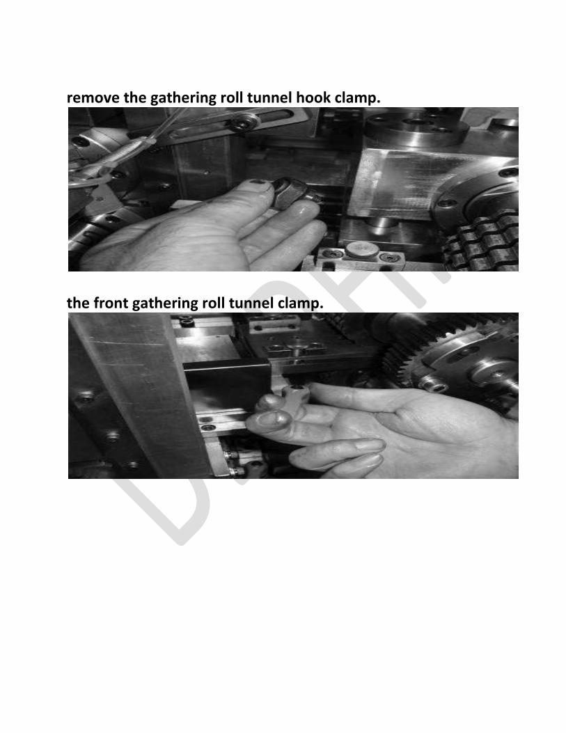
remove the gathering roll tunnel hook clamp.
the front gathering roll tunnel clamp.
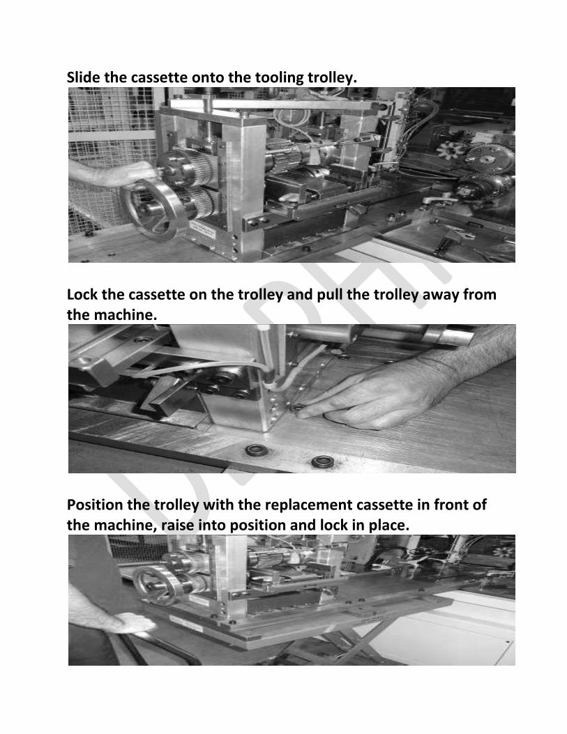
Slide the cassette onto the tooling trolley.
Lock the cassette on the trolley and pull the trolley away from the machine.
Position the trolley with the replacement cassette in front of the machine, raise into position and lock in place.
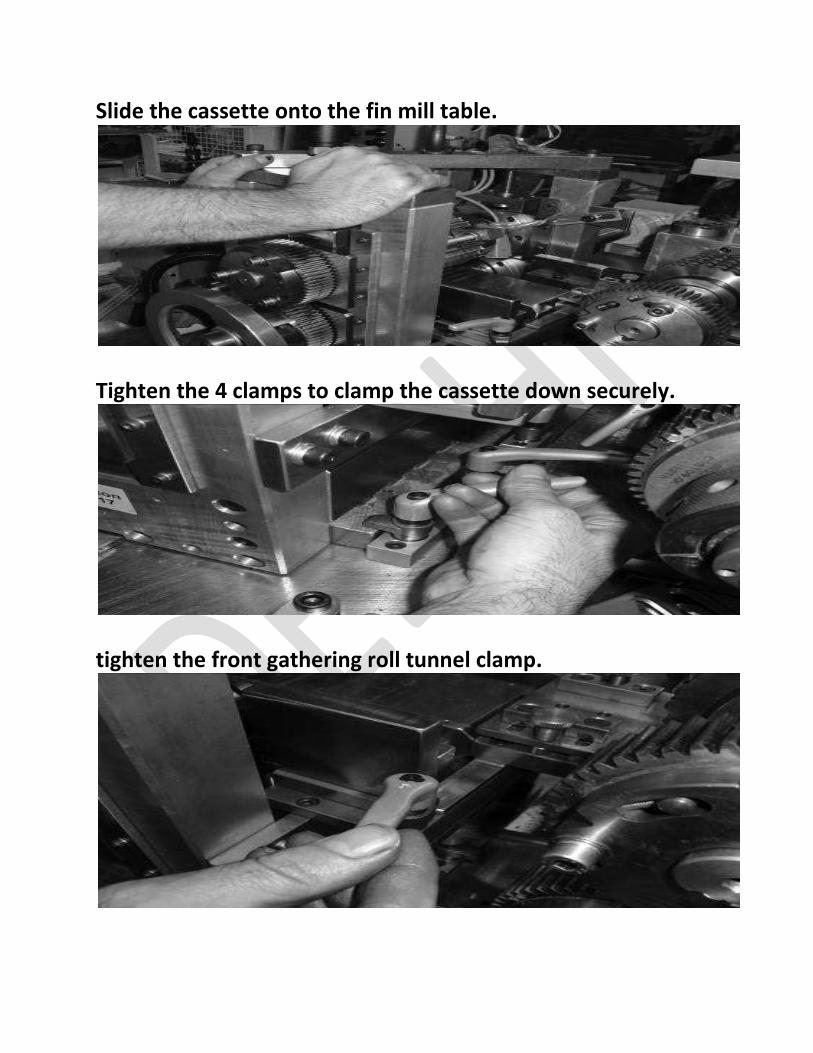
Slide the cassette onto the fin mill table.
Tighten the 4 clamps to clamp the cassette down securely.
tighten the front gathering roll tunnel clamp.
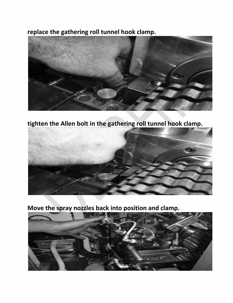
replace the gathering roll tunnel hook clamp.
tighten the Allen bolt in the gathering roll tunnel hook clamp.
Move the spray nozzles back into position and clamp.
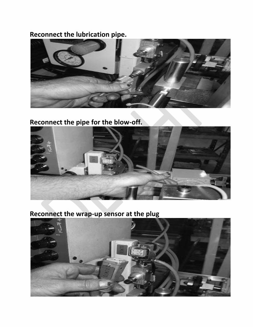
Reconnect the lubrication pipe.
Reconnect the pipe for the blow-off.
Reconnect the wrap-up sensor at the plug
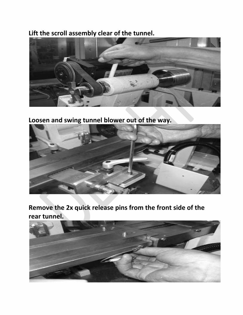
Lift the scroll assembly clear of the tunnel.
Loosen and swing tunnel blower out of the way.
Remove the 2x quick release pins from the front side of the rear tunnel.
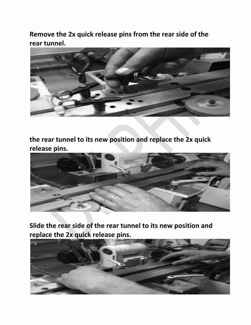
Remove the 2x quick release pins from the rear side of the rear tunnel.
the rear tunnel to its new position and replace the 2x quick release pins.
Slide the rear side of the rear tunnel to its new position and replace the 2x quick release pins.
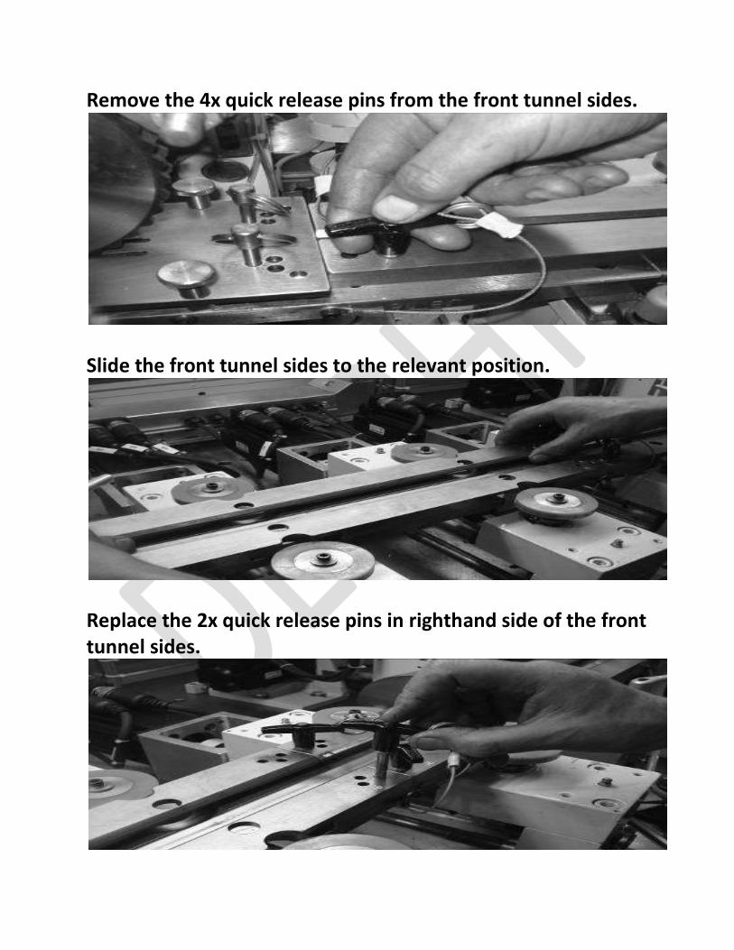
Remove the 4x quick release pins from the front tunnel sides.
Slide the front tunnel sides to the relevant position.
Replace the 2x quick release pins in righthand side of the front tunnel sides.
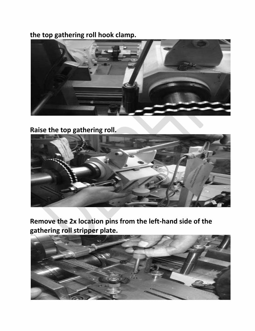
the top gathering roll hook clamp.
Raise the top gathering roll.
Remove the 2x location pins from the left-hand side of the gathering roll stripper plate.
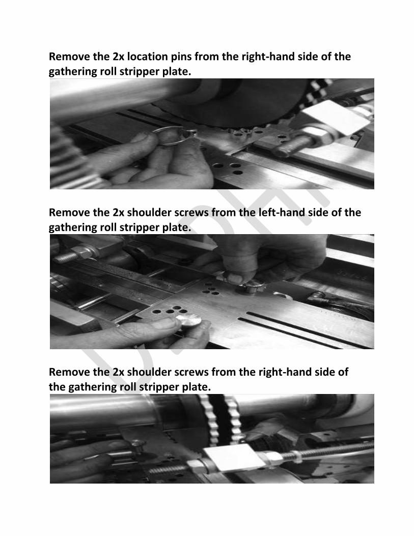
Remove the 2x location pins from the right-hand side of the gathering roll stripper plate.
Remove the 2x shoulder screws from the left-hand side of the gathering roll stripper plate.
Remove the 2x shoulder screws from the right-hand side of the gathering roll stripper plate.
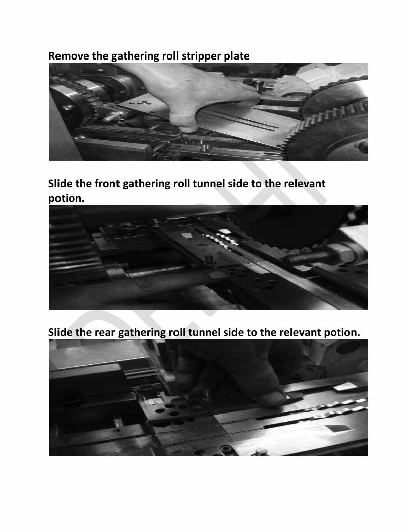
Remove the gathering roll stripper plate
Slide the front gathering roll tunnel side to the relevant potion.
Slide the rear gathering roll tunnel side to the relevant potion.
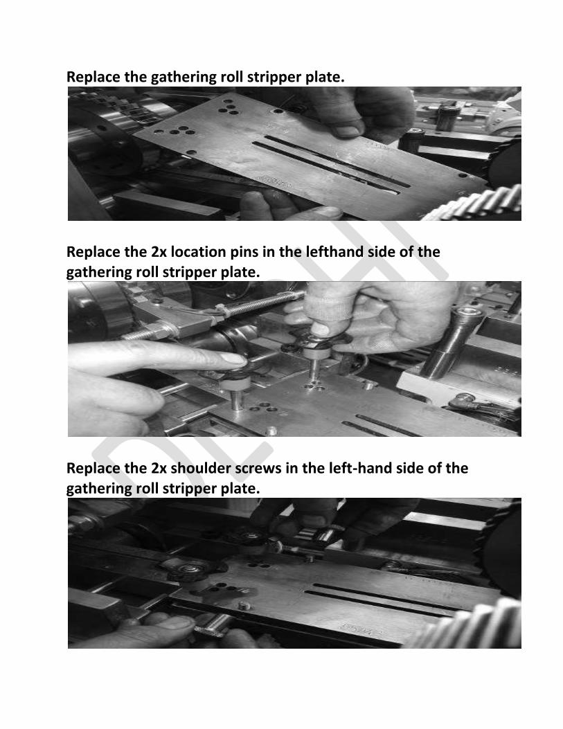
Replace the gathering roll stripper plate.
Replace the 2x location pins in the lefthand side of the gathering roll stripper plate.
Replace the 2x shoulder screws in the left-hand side of the gathering roll stripper plate.
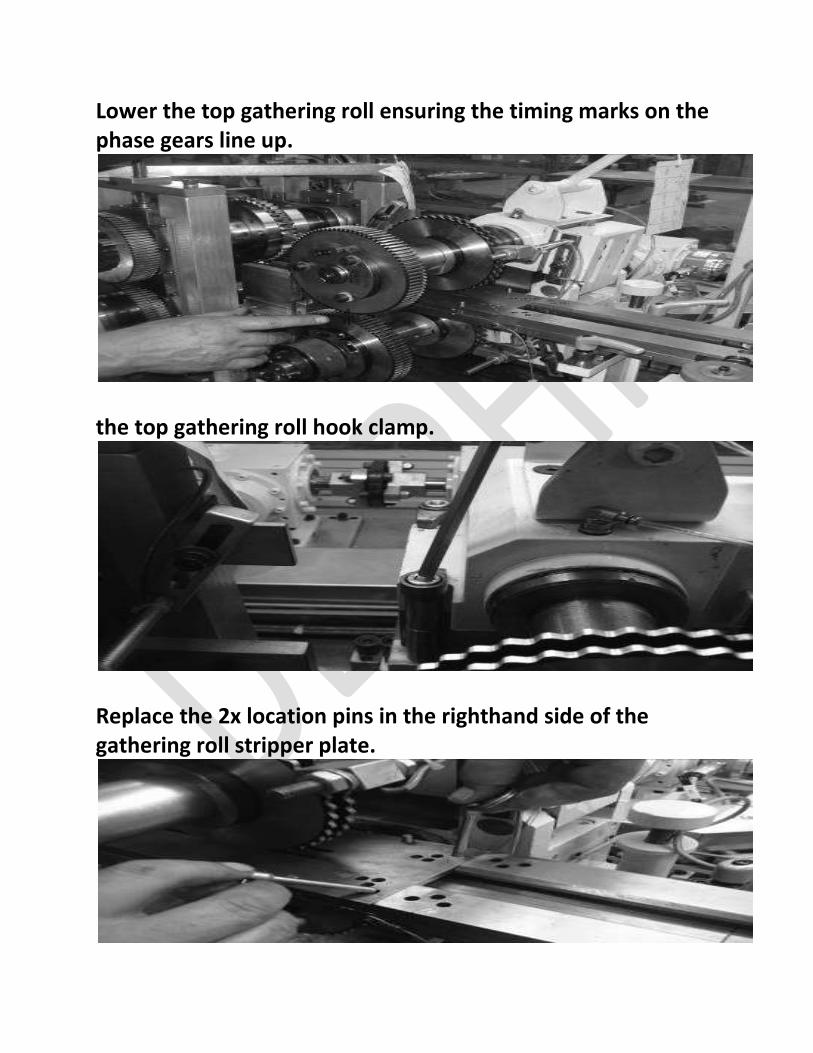
Lower the top gathering roll ensuring the timing marks on the phase gears line up.
the top gathering roll hook clamp.
Replace the 2x location pins in the righthand side of the gathering roll stripper plate.
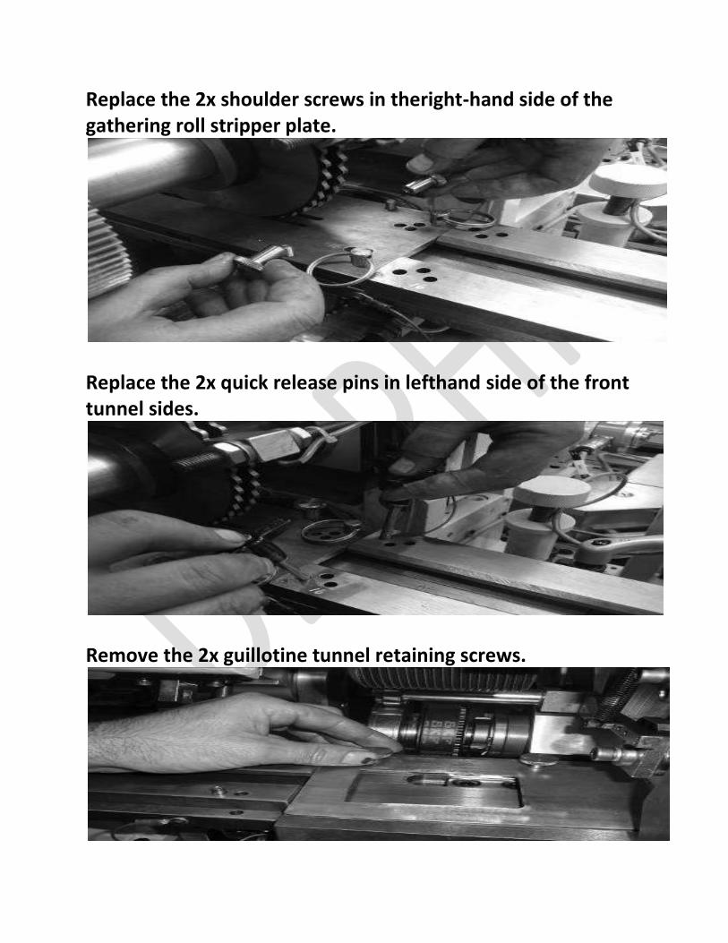
Replace the 2x shoulder screws in theright-hand side of the gathering roll stripper plate.
Replace the 2x quick release pins in lefthand side of the front tunnel sides.
Remove the 2x guillotine tunnel retaining screws.
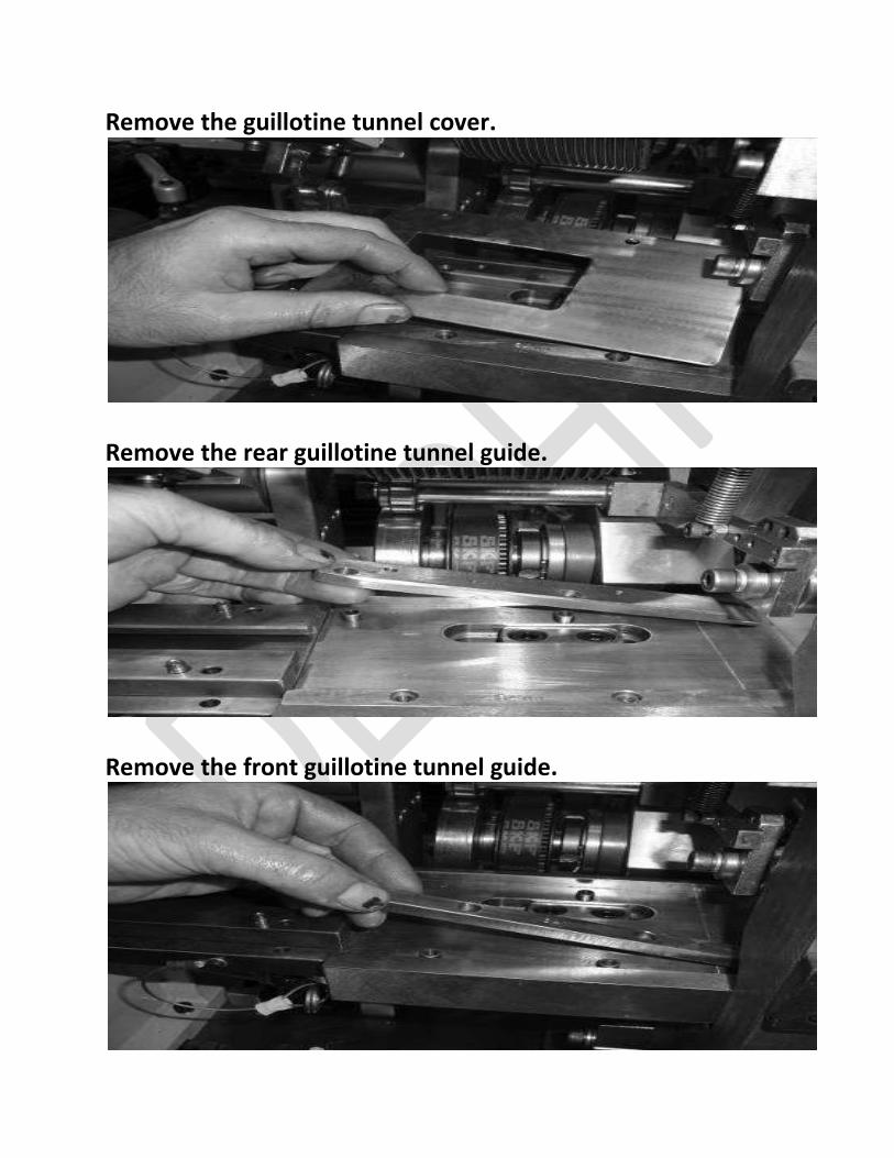
Remove the guillotine tunnel cover.
Remove the rear guillotine tunnel guide.
Remove the front guillotine tunnel guide.
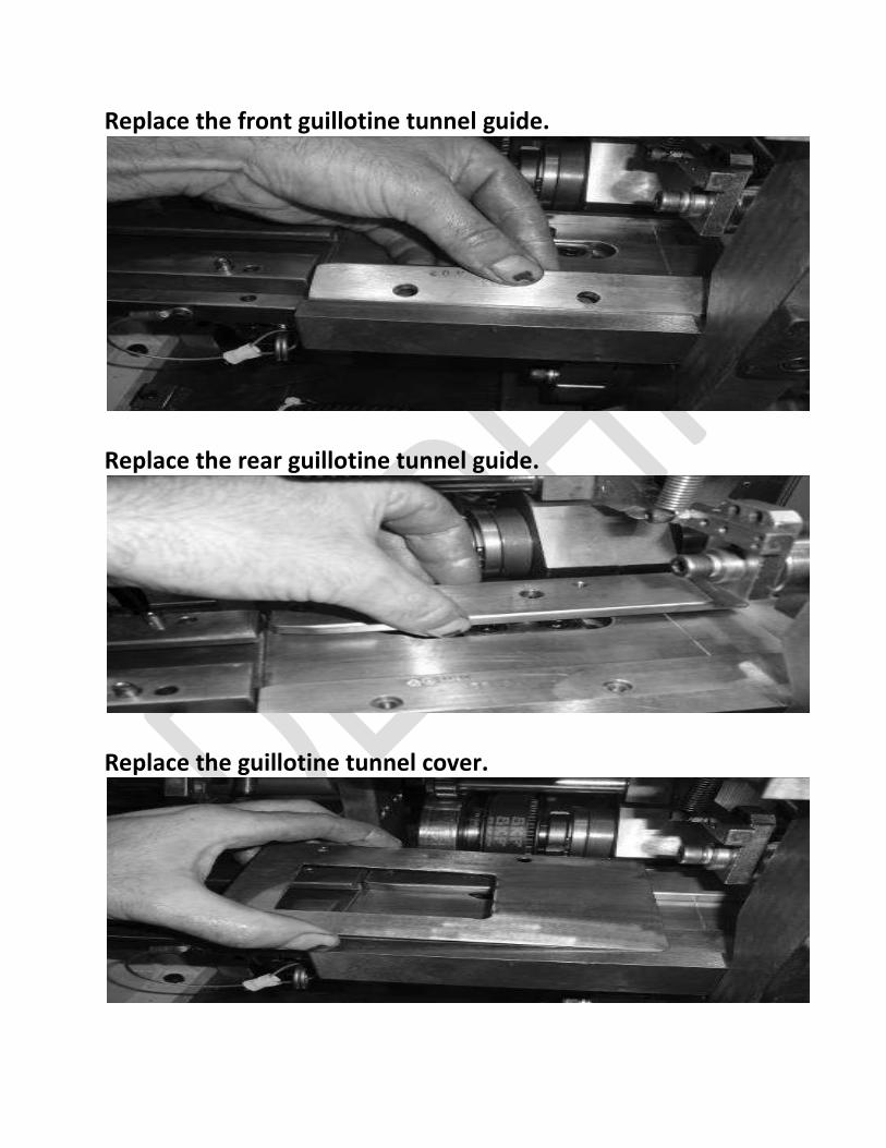
Replace the front guillotine tunnel guide.
Replace the rear guillotine tunnel guide.
Replace the guillotine tunnel cover.
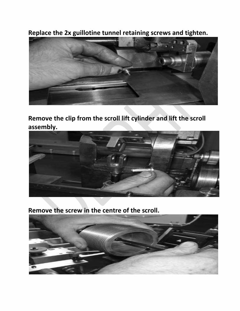
Replace the 2x guillotine tunnel retaining screws and tighten.
Remove the clip from the scroll lift cylinder and lift the scroll assembly.
Remove the screw in the centre of the scroll.
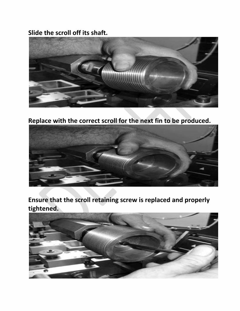
Slide the scroll off its shaft.
Replace with the correct scroll for the next fin to be produced.
Ensure that the scroll retaining screw is replaced and properly tightened.

Remove the Allen screw from the pecker blade.
Remove the pecker blade and replace with the correct one for the required fin pitch. Replace the Allen screw and secure.
Lower the scroll back onto its cylinder and lock in place with the clip.

Recommended
![[XLS] · Web viewGorakhpur - Maya Bazar 273005 0254 Greater Noida Greater Noida Cluster BINDU MITTAL 127185 Noida 201306 2321801](https://img.pdfslide.tips/doc/110x75/5ad1bee67f8b9a86158c562c/xls-viewgorakhpur-maya-bazar-273005-0254-greater-noida-greater-noida-cluster.jpg)