Case Study of LED PKG Field Failures
Discoloration
Rev. 1.0 2015-12-10
LEE SAK (Isaac,艾萨克艾萨克艾萨克艾萨克) Senior Engineer, Quality TeamLED Division, Semiconductor Business SAMSUNG ELECTRONICS
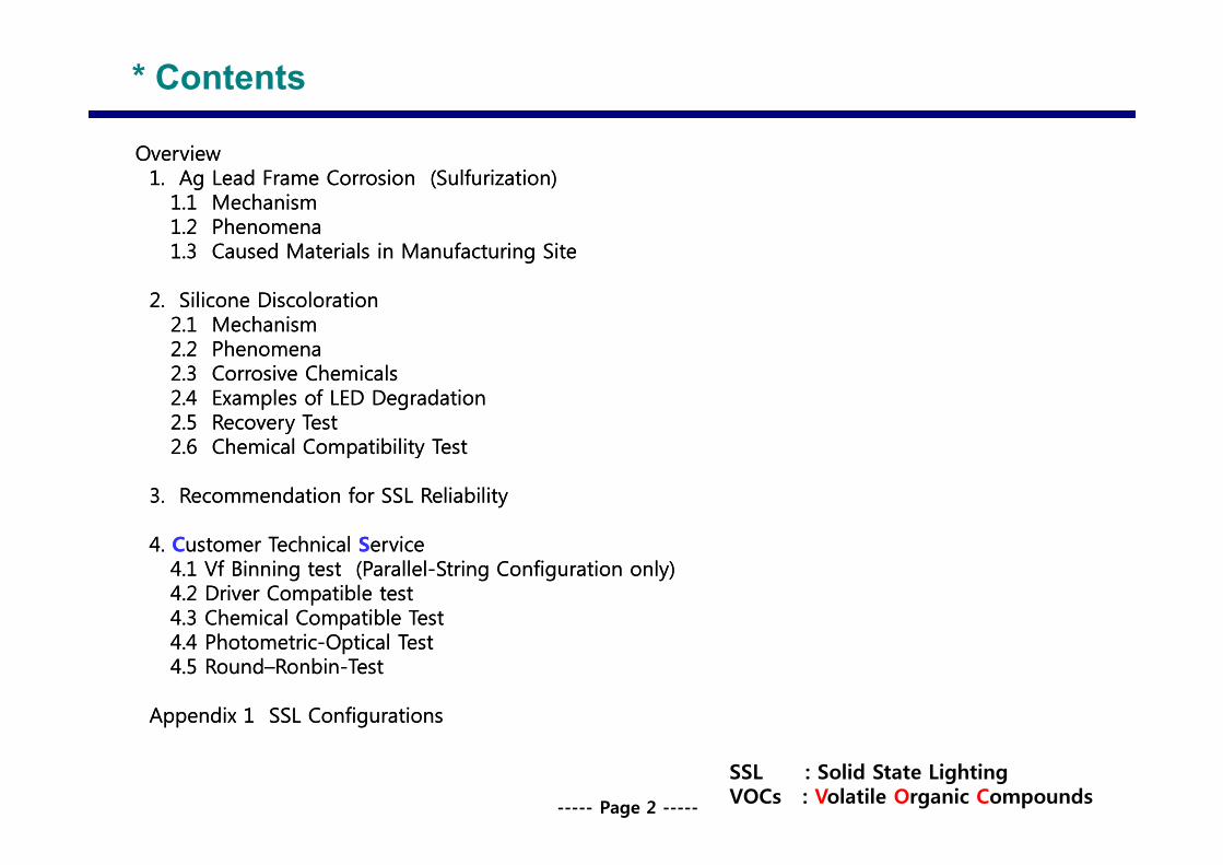
* Contents
Overview Overview 1. Ag Lead Frame Corrosion (1. Ag Lead Frame Corrosion (SulfurizationSulfurization) ) 1.1 Mechanism1.1 Mechanism1.2 Phenomena 1.2 Phenomena 1.3 Caused Materials in Manufacturing Site 1.3 Caused Materials in Manufacturing Site
2. Silicone Discoloration 2. Silicone Discoloration 2.1 Mechanism2.1 Mechanism2.2 Phenomena2.2 Phenomena2.3 Corrosive Chemicals 2.3 Corrosive Chemicals 2.4 Examples of LED Degradation 2.4 Examples of LED Degradation 2.5 Recovery Test2.5 Recovery Test2.6 Chemical Compatibility Test 2.6 Chemical Compatibility Test
----- Page 2 -----
2.5 Recovery Test2.5 Recovery Test2.6 Chemical Compatibility Test 2.6 Chemical Compatibility Test
3. Recommendation for SSL Reliability 3. Recommendation for SSL Reliability 4. 4. CCustomer ustomer Technical Technical SService ervice 4.1 4.1 VfVf Binning test (ParallelBinning test (Parallel--String Configuration only) String Configuration only) 4.2 Driver Compatible test 4.2 Driver Compatible test 4.3 Chemical Compatible Test4.3 Chemical Compatible Test4.4 Photometric4.4 Photometric--Optical Test Optical Test 4.5 Round4.5 Round––RonbinRonbin--Test Test
Appendix 1 SSL ConfigurationsAppendix 1 SSL Configurations
SSL : Solid State LightingVOCs : Volatile Organic Compounds
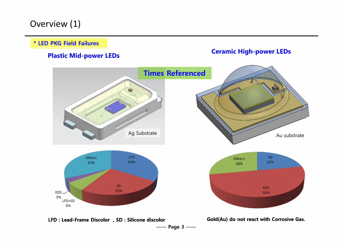
Overview (1)
Ceramic High-power LEDsPlastic Mid-power LEDs
Times Referenced
* LED PKG Field Failures
----- Page 3 -----LFD : LeadLFD : Lead--Frame Discolor , SD : Silicone discolorFrame Discolor , SD : Silicone discolor
Ag Substrate Au substrate
Gold(Au) do not react with Corrosive Gas.Gold(Au) do not react with Corrosive Gas.
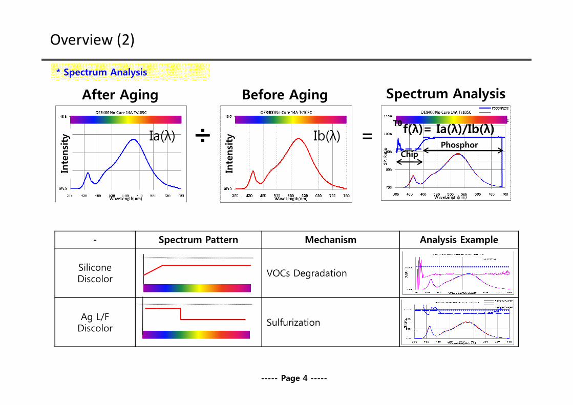
Overview (2)
Before AgingAfter Aging
÷÷÷÷ =
Inten
sity
Inten
sity Ib(λ)Ia(λ)
Spectrum Analysisf(λ)= Ia(λ)/Ib(λ)
PhosphorChip
T0T0T0T0
* Spectrum Analysis
----- Page 4 -----
- Spectrum Pattern Mechanism Analysis Example
SiliconeDiscolor VOCs Degradation
Ag L/FDiscolor Sulfurization
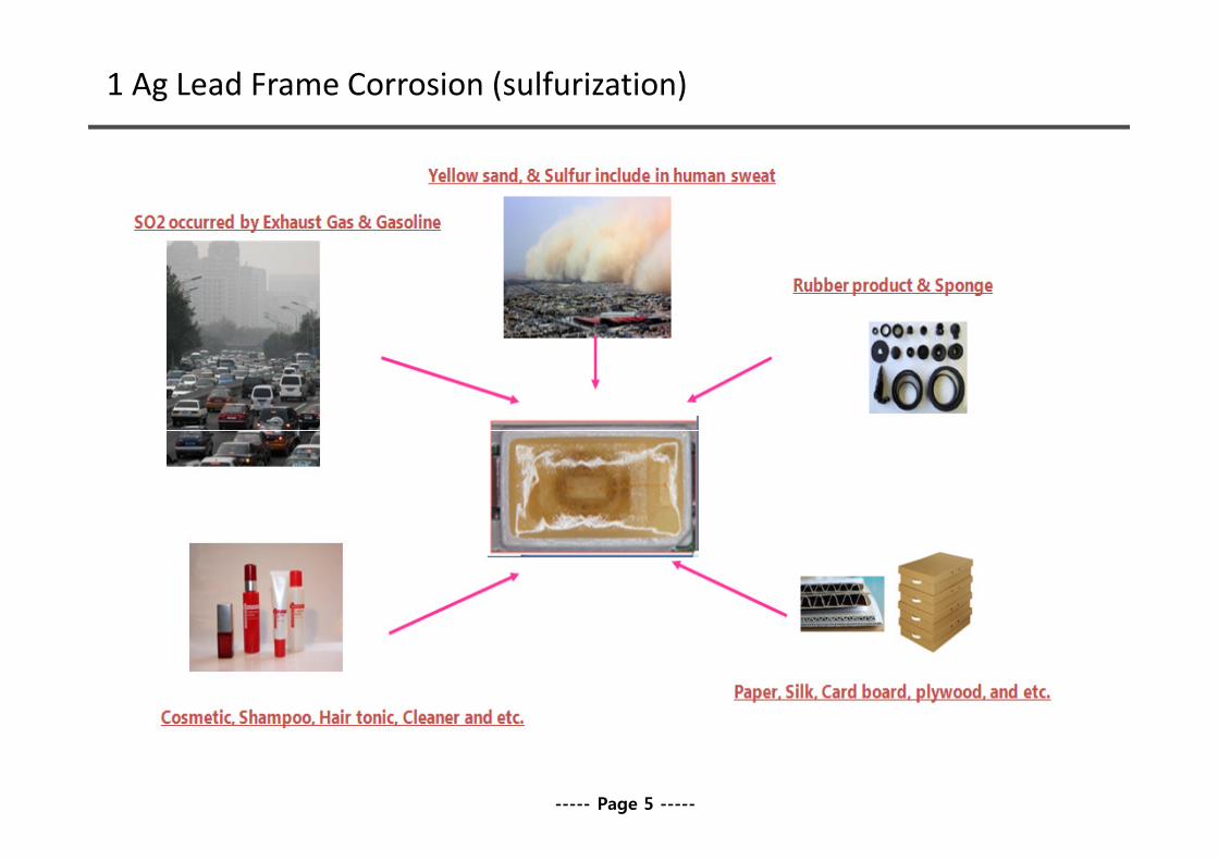
1 Ag Lead Frame Corrosion (sulfurization)
----- Page 5 -----

1.1 Mechanism (Sulfurization)
Discolor image
2Ag + H2S + ½ O2 → Ag2S + H2O
Corrosion is accelerated by Heat and Humidity
Blackish Particle
----- Page 6 -----
Discolor image
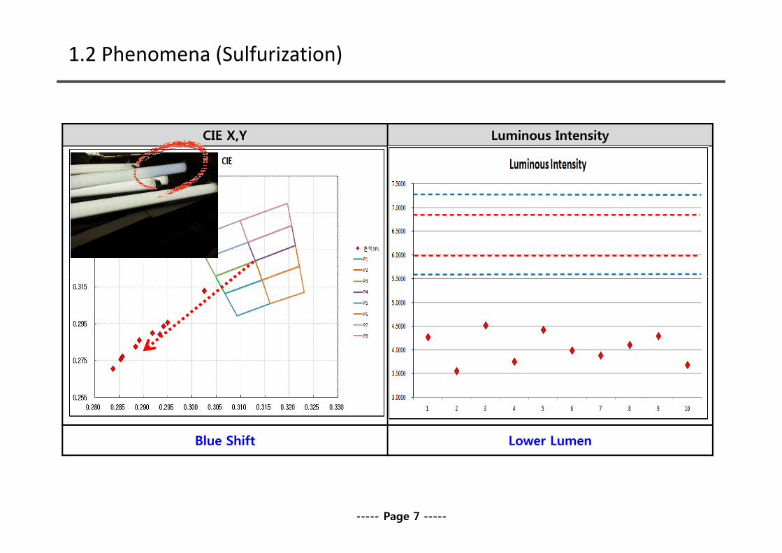
1.2 Phenomena (Sulfurization)
CIE X,Y Luminous Intensity
----- Page 7 -----
Blue Shift Lower Lumen
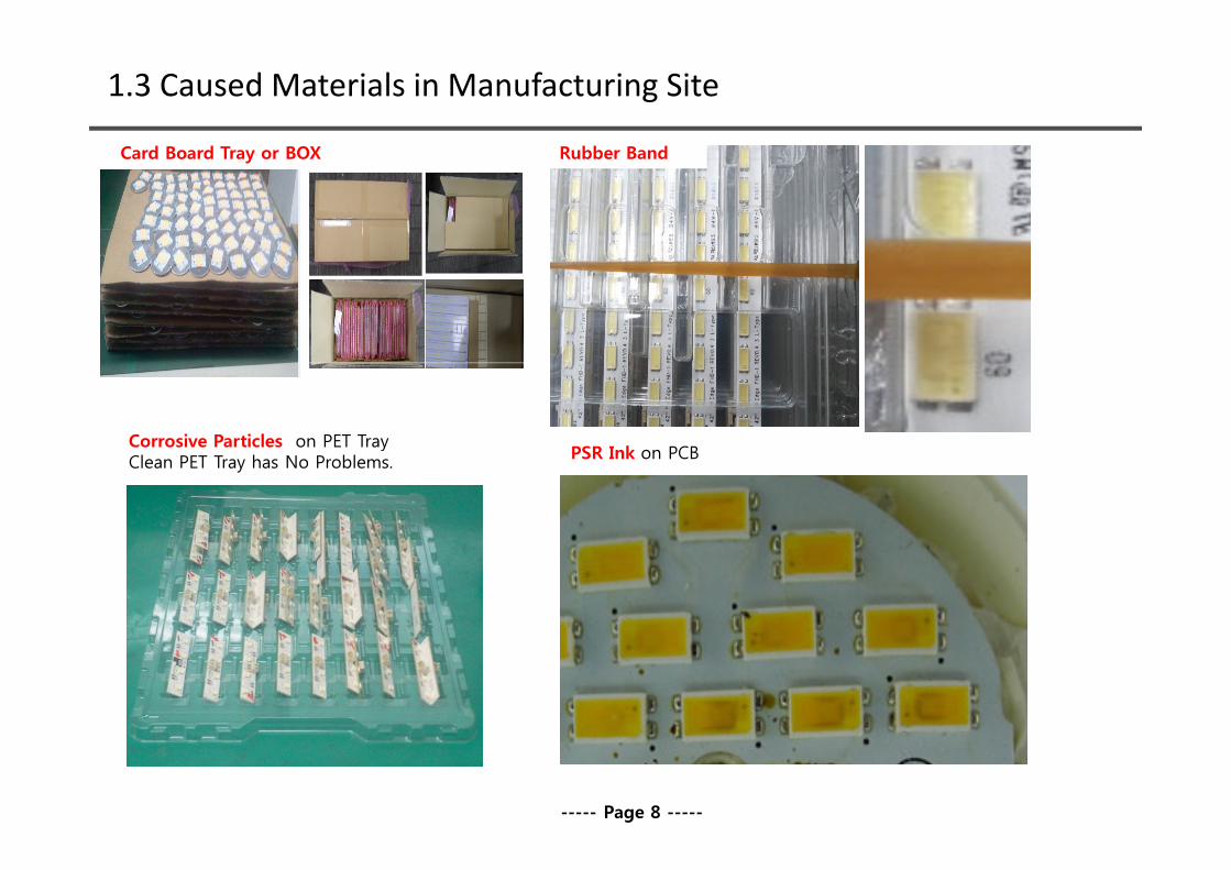
1.3 Caused Materials in Manufacturing Site
Card Board Tray or BOX
Corrosive Particles on PET Tray
Rubber Band
----- Page 8 -----
Corrosive Particles on PET Tray Clean PET Tray has No Problems. PSR Ink on PCB
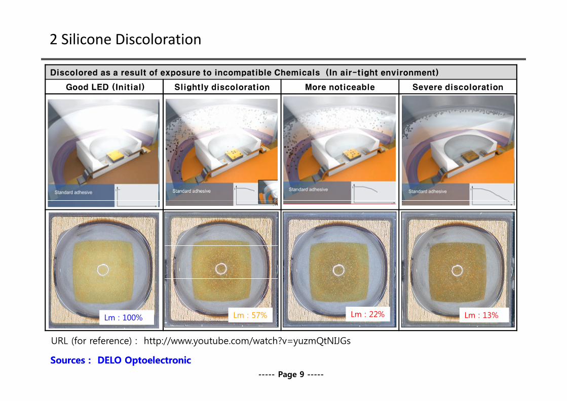
2 Silicone Discoloration
Discolored as a result of exposure to incompatible Chemicals (In air-tight environment)
Good LED (Initial) Slightly discoloration More noticeable Severe discoloration
----- Page 9 -----
Lm : 100% Lm : 57% Lm : 22% Lm : 13%
URL (for reference) : http://www.youtube.com/watch?v=yuzmQtNIJGsSources : DELO OptoelectronicSources : DELO Optoelectronic
2.1 Mechanism
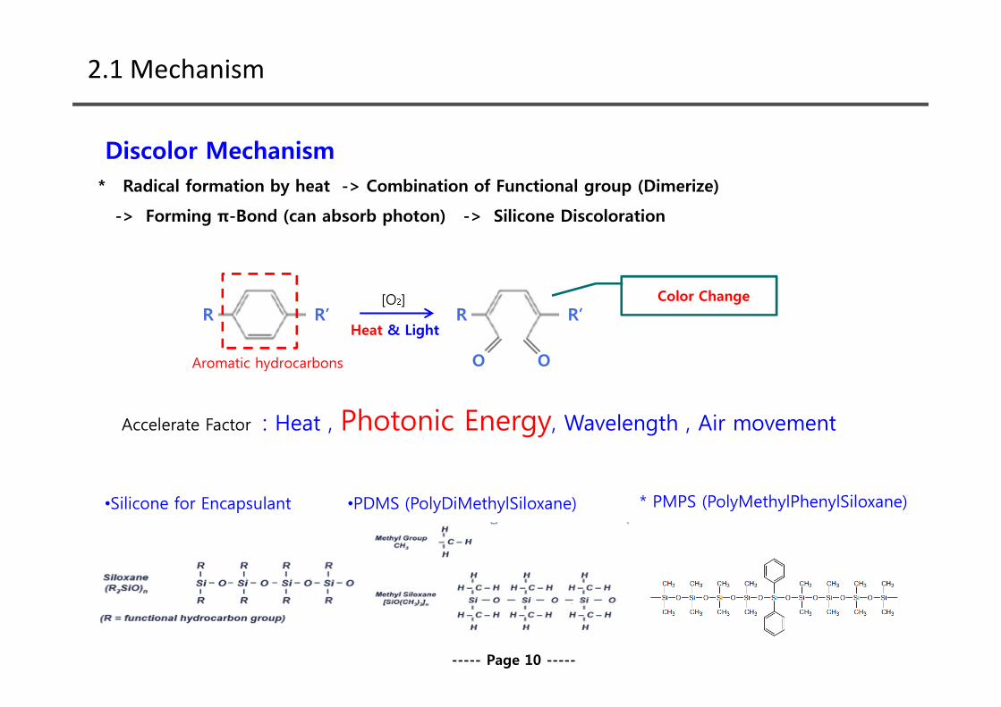
Discolor Mechanism
R R’ Heat & Light[O2] R R’
O O
Color Change
Aromatic hydrocarbons
* Radical formation by heat -> Combination of Functional group (Dimerize)-> Forming π-Bond (can absorb photon) -> Silicone Discoloration
----- Page 10 -----
O OAromatic hydrocarbons
Accelerate Factor : Heat , Photonic Energy, Wavelength , Air movement
•Silicone for Encapsulant * PMPS (PolyMethylPhenylSiloxane) •PDMS (PolyDiMethylSiloxane)
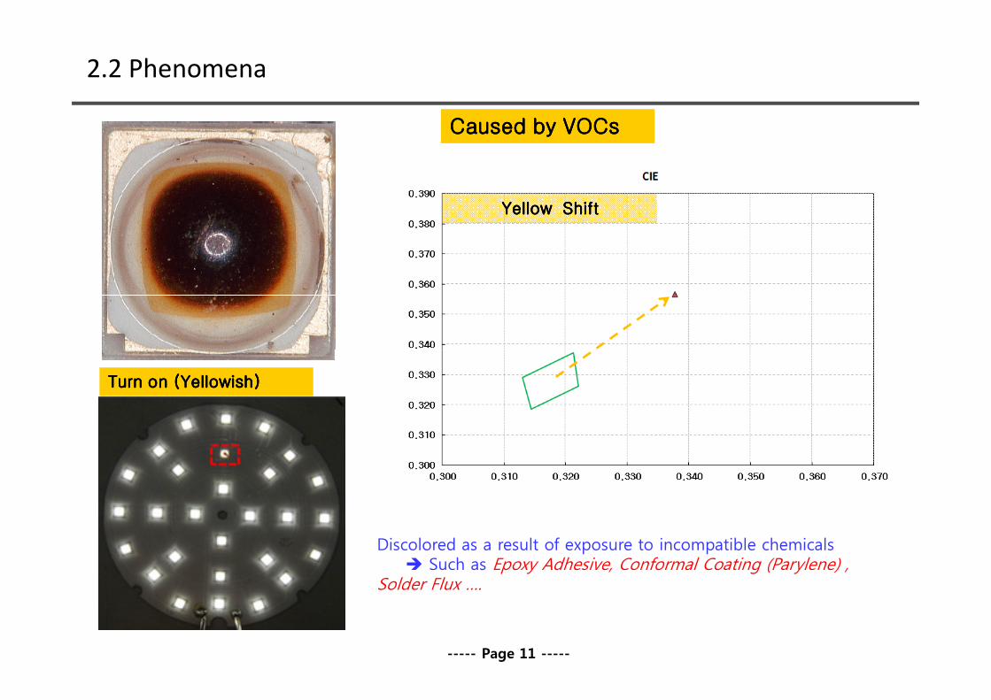
2.2 Phenomena
Yellow ShiftYellow ShiftYellow ShiftYellow Shift
Caused by VOCs Caused by VOCs Caused by VOCs Caused by VOCs
----- Page 11 -----
Turn on (Yellowish) Turn on (Yellowish) Turn on (Yellowish) Turn on (Yellowish)
Discolored as a result of exposure to incompatible chemicals � Such as Epoxy Adhesive, Conformal Coating (Parylene) ,
Solder Flux ….
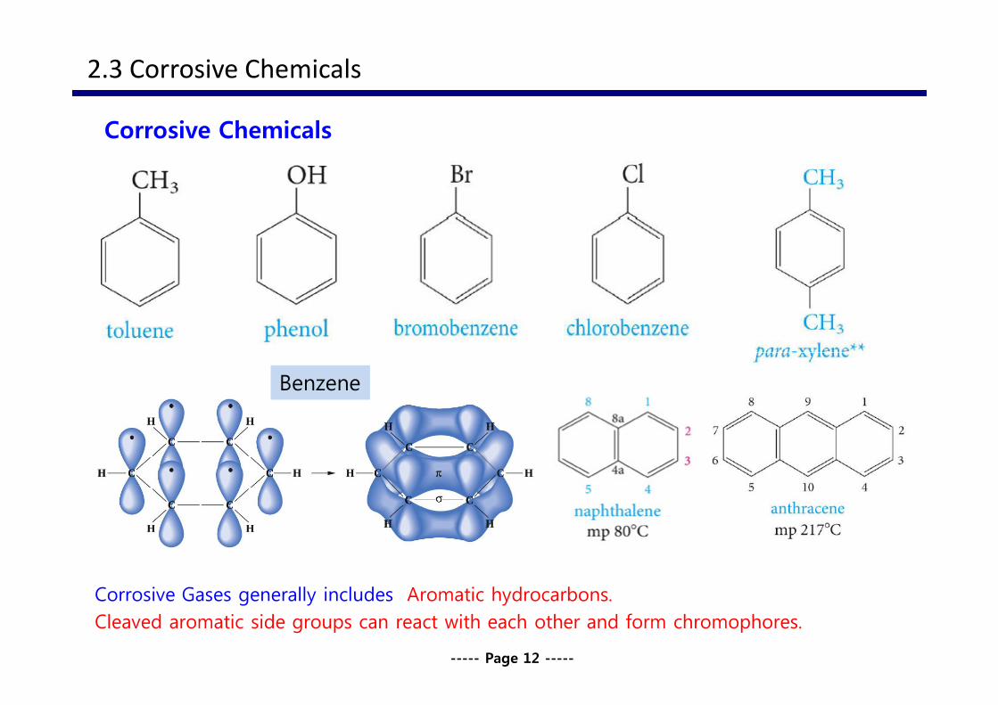
2.3 Corrosive Chemicals
Corrosive Chemicals
----- Page 12 -----
Corrosive Gases generally includes Aromatic hydrocarbons.Cleaved aromatic side groups can react with each other and form chromophores.
Benzene
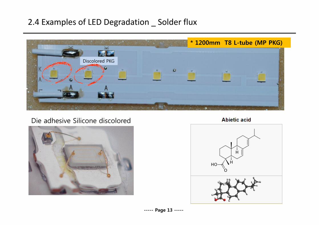
2.4 Examples of LED Degradation _ Solder flux
Discolored PKG
* 1200mm T8 L-tube (MP PKG)
----- Page 13 -----
Die adhesive Silicone discolored
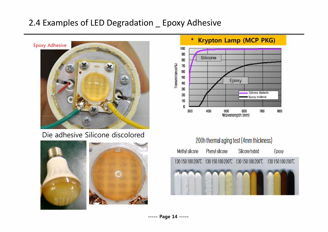
2.4 Examples of LED Degradation _ Epoxy Adhesive
Epoxy Adhesive * Krypton Lamp (MCP PKG)
----- Page 14 -----
Die adhesive Silicone discolored

2.4 Examples of LED Degradation _ PSR
* 100W Street light (HP PKG)
FR4 PCBCaused by poor Thermal Design (FR4 PCB)
----- Page 15 -----
Discolored Metal PCBNon Discolored
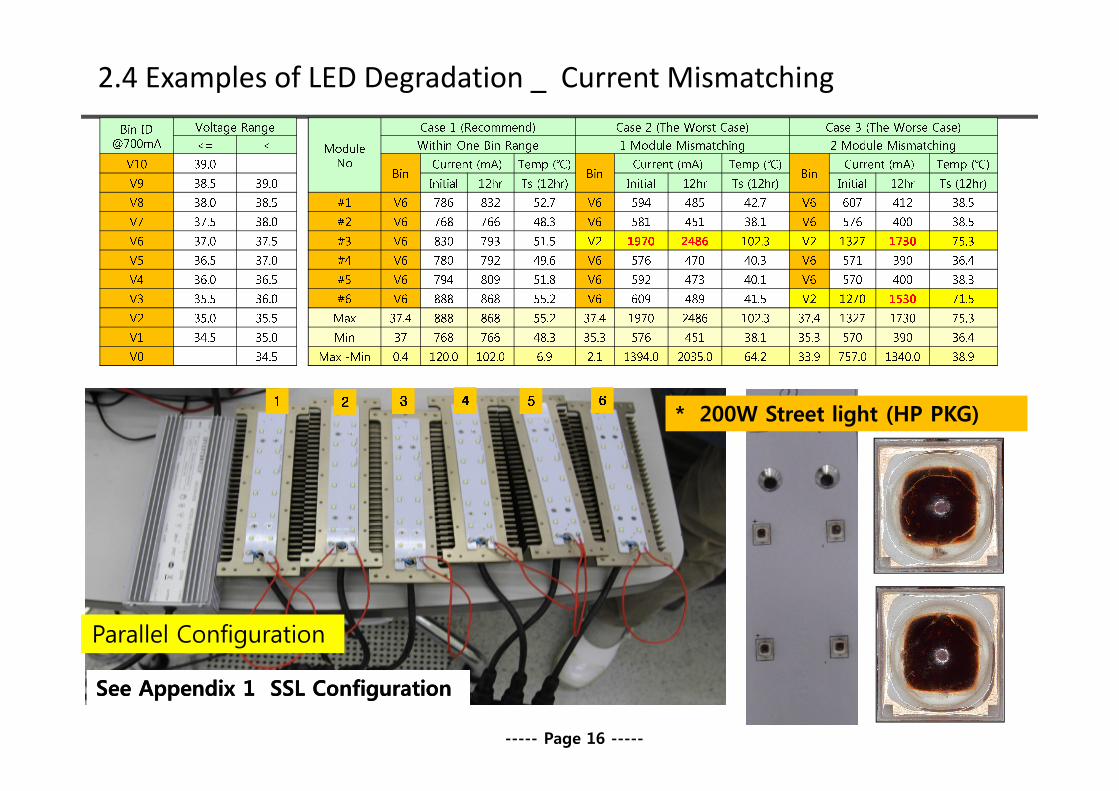
2.4 Examples of LED Degradation _ Current MismatchingBin ID@700mA Voltage Range ModuleNo Case 1 (Recommend) Case 2 (The Worst Case) Case 3 (The Worse Case)<= < Within One Bin Range 1 Module Mismatching 2 Module MismatchingV10 39.0 Bin Current (mA) Temp (℃) Bin Current (mA) Temp (℃) Bin Current (mA) Temp (℃)V9 38.5 39.0 Initial 12hr Ts (12hr) Initial 12hr Ts (12hr) Initial 12hr Ts (12hr)V8 38.0 38.5 #1 V6 786 832 52.7 V6 594 485 42.7 V6 607 412 38.5V7 37.5 38.0 #2 V6 768 766 48.3 V6 581 451 38.1 V6 576 400 38.5V6 37.0 37.5 #3 V6 830 793 51.5 V2 1970 2486 102.3 V2 1327 1730 75.3V5 36.5 37.0 #4 V6 780 792 49.6 V6 576 470 40.3 V6 571 390 36.4V4 36.0 36.5 #5 V6 794 809 51.8 V6 592 473 40.1 V6 570 400 38.3V3 35.5 36.0 #6 V6 888 868 55.2 V6 609 489 41.5 V2 1270 1530 71.5V2 35.0 35.5 Max 37.4 888 868 55.2 37.4 1970 2486 102.3 37.4 1327 1730 75.3V1 34.5 35.0 Min 37 768 766 48.3 35.3 576 451 38.1 35.3 570 390 36.4V0 34.5 Max -Min 0.4 120.0 102.0 6.9 2.1 1394.0 2035.0 64.2 33.9 757.0 1340.0 38.9 1111 2222 3333 4444 5555 6666
----- Page 16 -----
1111 2222 3333 4444 5555 6666 * 200W Street light (HP PKG)
See Appendix 1 SSL Configuration See Appendix 1 SSL Configuration Parallel Configuration
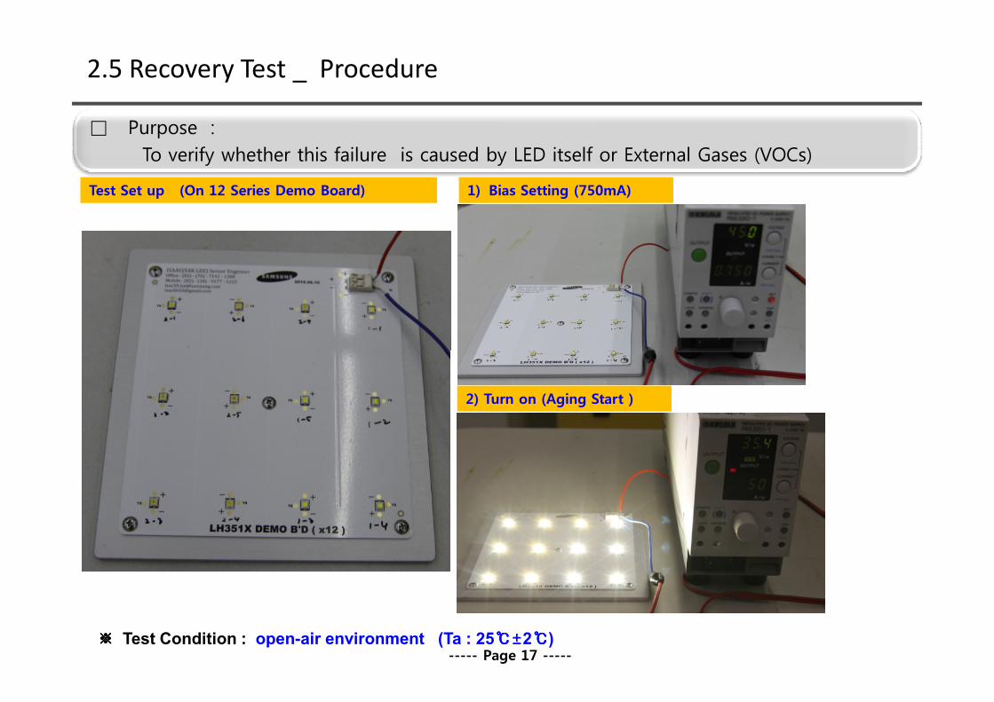
2.5 Recovery Test _ Procedure
� Purpose : To verify whether this failure is caused by LED itself or External Gases (VOCs)
1) Bias Setting (750mA) Test Set up (On 12 Series Demo Board)
----- Page 17 -----
2) Turn on (Aging Start )
※※※※ Test Condition : open-air environment (Ta : 25℃℃℃℃±2℃℃℃℃)

2.5 Recovery Test _ Result
Recovery TestInitial After 60hrs After 168hrs Luminous Flux
#1
----- Page 18 -----
#2
#3
* Examples showing the reversibility of VOCs discoloration
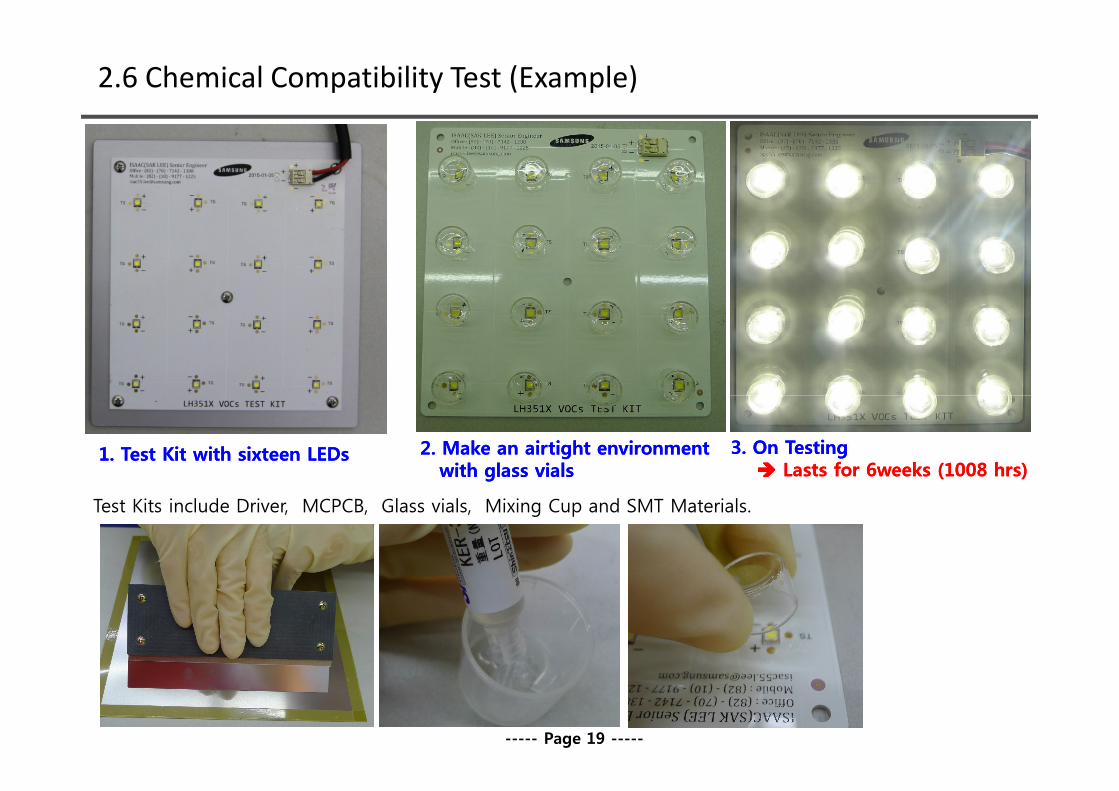
2.6 Chemical Compatibility Test (Example)
----- Page 19 -----
3. On Testing3. On Testing�������� Lasts for 6weeks (1008 hrs)Lasts for 6weeks (1008 hrs)1. Test Kit with sixteen LEDs1. Test Kit with sixteen LEDs 2. Make an airtight environment 2. Make an airtight environment
with glass vialswith glass vialsTest Kits include Driver, MCPCB, Glass vials, Mixing Cup and SMT Materials.

2.6 Chemical Compatibility Test
* Recommend Test Condition (LH351B) - Ts range : 75℃ ~ 85℃ (@Ta 25℃) - Current : 700mA ~ 1050mA Constant Current Mode - Duration : 6 weeks (1008 hrs)
Gen 1
----- Page 20 -----
Gen 2
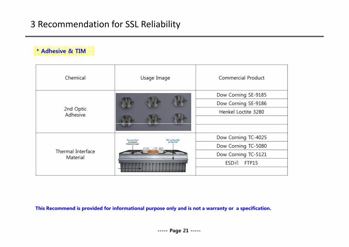
3 Recommendation for SSL Reliability
Chemical Usage Image Commercial Product
2nd OpticAdhesive
Dow Corning SE-9185Dow Corning SE-9186Henkel Loctite 3280
* Adhesive & TIM
----- Page 21 -----
Thermal InterfaceMaterial
Dow Corning TC-4025Dow Corning TC-5080Dow Corning TC-5121
ESD社 FTP15
This Recommend is provided for informational purpose only and is not a warranty or a specification.
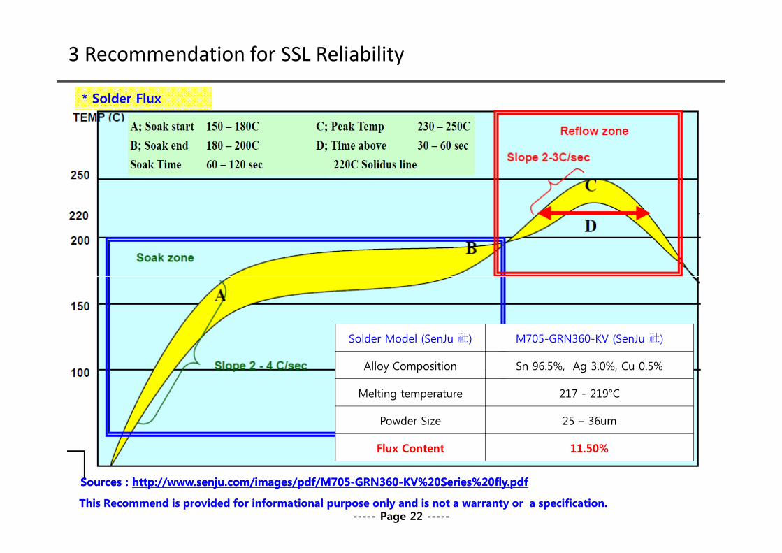
3 Recommendation for SSL Reliability
* Solder Flux
----- Page 22 -----
Solder Model (SenJu 社) M705-GRN360-KV (SenJu 社)Alloy Composition Sn 96.5%, Ag 3.0%, Cu 0.5%Melting temperature 217 - 219°C
Powder Size 25 – 36umFlux Content 11.50%
This Recommend is provided for informational purpose only and is not a warranty or a specification.
Sources : Sources : http://www.senju.com/images/pdf/M705http://www.senju.com/images/pdf/M705--GRN360GRN360--KV%20Series%20fly.pdfKV%20Series%20fly.pdf

3 Recommendation for SSL Reliability
* PSR
----- Page 23 -----
* Recommended White Solder Resist Ink 1) LEW7S (Taiyo ink mfg.co.ltd. )
This Recommend is provided for informational purpose only and is not a warranty or a specification.
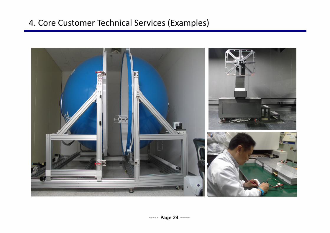
4. Core Customer Technical Services (Examples)
----- Page 24 -----
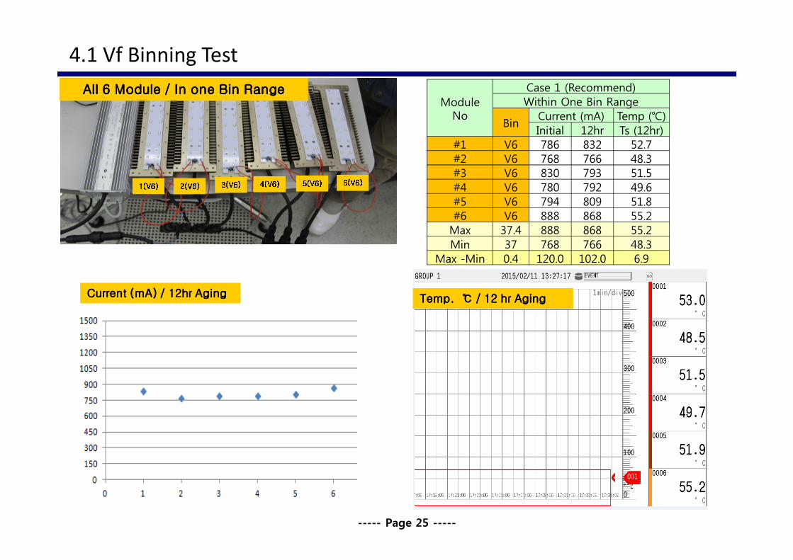
4.1 Vf Binning Test
1(V6)1(V6)1(V6)1(V6)All 6 Module / In one Bin RangeAll 6 Module / In one Bin RangeAll 6 Module / In one Bin RangeAll 6 Module / In one Bin Range
2(V6)2(V6)2(V6)2(V6) 3(V6)3(V6)3(V6)3(V6) 4(V6)4(V6)4(V6)4(V6) 5(V6)5(V6)5(V6)5(V6) 6(V6)6(V6)6(V6)6(V6)ModuleNo
Case 1 (Recommend)Within One Bin Range
Bin Current (mA) Temp (℃)Initial 12hr Ts (12hr)
#1 V6 786 832 52.7#2 V6 768 766 48.3#3 V6 830 793 51.5#4 V6 780 792 49.6#5 V6 794 809 51.8#6 V6 888 868 55.2Max 37.4 888 868 55.2Min 37 768 766 48.3
Max -Min 0.4 120.0 102.0 6.9
----- Page 25 -----
Temp. Temp. Temp. Temp. ℃ ℃ ℃ ℃ / 12 hr Aging/ 12 hr Aging/ 12 hr Aging/ 12 hr AgingCurrent (Current (Current (Current (mAmAmAmA) / 12hr Aging ) / 12hr Aging ) / 12hr Aging ) / 12hr Aging
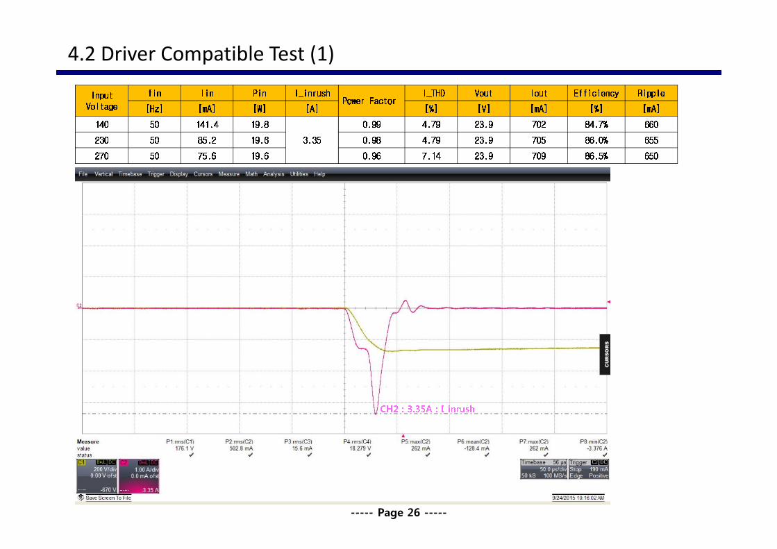
4.2 Driver Compatible Test (1) InputInputInputInputVoltageVoltageVoltageVoltage finfinfinfin IinIinIinIin PinPinPinPin I_inrushI_inrushI_inrushI_inrush Power FactorPower FactorPower FactorPower Factor I_THDI_THDI_THDI_THD VoutVoutVoutVout IoutIoutIoutIout EfficiencyEfficiencyEfficiencyEfficiency RippleRippleRippleRipple[Hz][Hz][Hz][Hz] [[[[mAmAmAmA]]]] [W][W][W][W] [A][A][A][A] [%][%][%][%] [V][V][V][V] [[[[mAmAmAmA]]]] [%][%][%][%] [[[[mAmAmAmA]]]]140140140140 50505050 141.4141.4141.4141.4 19.819.819.819.8 3.353.353.353.35 0.990.990.990.99 4.794.794.794.79 23.923.923.923.9 702702702702 84.7%84.7%84.7%84.7% 660660660660230230230230 50505050 85.285.285.285.2 19.619.619.619.6 0.980.980.980.98 4.794.794.794.79 23.923.923.923.9 705705705705 86.0%86.0%86.0%86.0% 655655655655270270270270 50505050 75.675.675.675.6 19.619.619.619.6 0.960.960.960.96 7.147.147.147.14 23.923.923.923.9 709709709709 86.5%86.5%86.5%86.5% 650650650650
----- Page 26 -----
CH2 : 3.35A : I_inrush
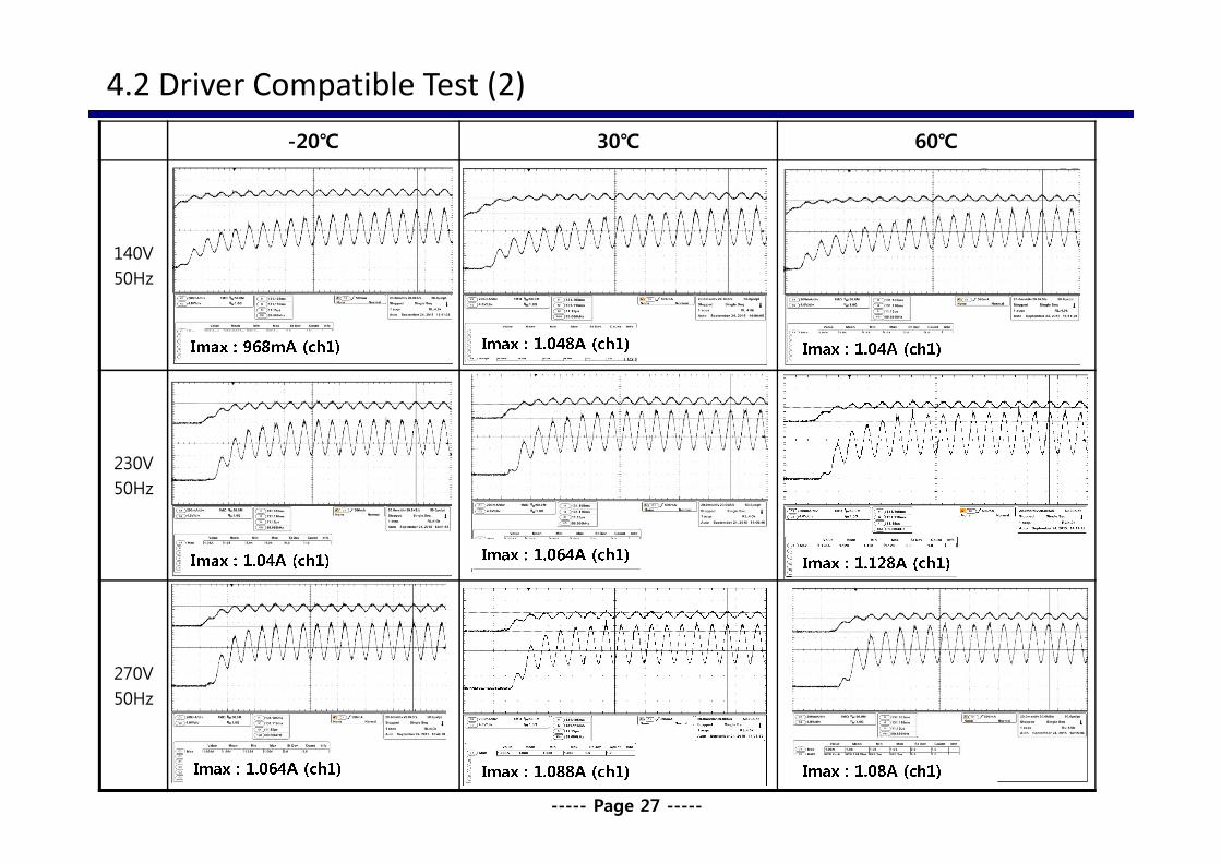
4.2 Driver Compatible Test (2)
-20℃ 30℃ 60℃
140V50Hz Imax : 968mA (ch1) Imax : 1.048A (ch1) Imax : 1.04A (ch1)
----- Page 27 -----
230V50Hz
270V50Hz
Imax : 1.04A (ch1) Imax : 1.064A (ch1)
Imax : 1.064A (ch1) Imax : 1.088A (ch1)
Imax : 1.128A (ch1) Imax : 1.08A (ch1)
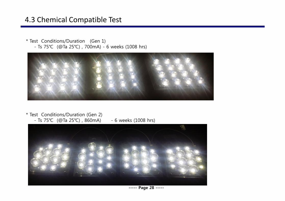
4.3 Chemical Compatible Test
* Test Conditions/Duration (Gen 1)- Ts 75℃ (@Ta 25℃) , 700mA) - 6 weeks (1008 hrs)
----- Page 28 -----
* Test Conditions/Duration (Gen 2) - Ts 75℃ (@Ta 25℃) , 860mA) - 6 weeks (1008 hrs)
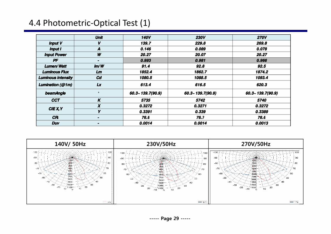
4.4 Photometric-Optical Test (1)
UnitUnitUnitUnit 140V140V140V140V 230V230V230V230V 270V270V270V270V
InputInputInputInput VVVV VVVV 139.7 139.7 139.7 139.7 229.8 229.8 229.8 229.8 269.8 269.8 269.8 269.8
InputInputInputInput IIII AAAA 0.146 0.146 0.146 0.146 0.089 0.089 0.089 0.089 0.078 0.078 0.078 0.078
Input PowerInput PowerInput PowerInput Power WWWW 20.27 20.27 20.27 20.27 20.07 20.07 20.07 20.07 20.27 20.27 20.27 20.27
PFPFPFPF ---- 0.993 0.993 0.993 0.993 0.981 0.981 0.981 0.981 0.966 0.966 0.966 0.966
Lumen/ WattLumen/ WattLumen/ WattLumen/ Watt lm/ Wlm/ Wlm/ Wlm/ W 91.4 91.4 91.4 91.4 92.8 92.8 92.8 92.8 92.5 92.5 92.5 92.5
Luminous FluxLuminous FluxLuminous FluxLuminous Flux LmLmLmLm 1852.4 1852.4 1852.4 1852.4 1862.7 1862.7 1862.7 1862.7 1874.2 1874.2 1874.2 1874.2
LuminousLuminousLuminousLuminous intensityintensityintensityintensity CdCdCdCd 1080.5 1080.5 1080.5 1080.5 1088.5 1088.5 1088.5 1088.5 1093.4 1093.4 1093.4 1093.4
LuminationLuminationLuminationLumination (@(@(@(@1111m)m)m)m) LxLxLxLx 613.4 613.4 613.4 613.4 616.5 616.5 616.5 616.5 620.3 620.3 620.3 620.3
beamAnglebeamAnglebeamAnglebeamAngle ° 60.3~ 139.7(90.9)60.3~ 139.7(90.9)60.3~ 139.7(90.9)60.3~ 139.7(90.9) 60.3~ 139.7(90.9)60.3~ 139.7(90.9)60.3~ 139.7(90.9)60.3~ 139.7(90.9) 60.3~ 139.7(90.9)60.3~ 139.7(90.9)60.3~ 139.7(90.9)60.3~ 139.7(90.9)
CCTCCTCCTCCT KKKK 5735 5735 5735 5735 5742 5742 5742 5742 5740 5740 5740 5740
CIE CIE CIE CIE X,YX,YX,YX,YXXXX 0.32720.32720.32720.3272 0.32710.32710.32710.3271 0.32720.32720.32720.3272
YYYY 0.33910.33910.33910.3391 0.3390.3390.3390.339 0.33890.33890.33890.3389
CRICRICRICRI ---- 76.876.876.876.8 76.776.776.776.7 76.676.676.676.6
----- Page 29 -----
CRICRICRICRI ---- 76.876.876.876.8 76.776.776.776.7 76.676.676.676.6
DuvDuvDuvDuv ---- 0.00140.00140.00140.0014 0.00140.00140.00140.0014 0.00130.00130.00130.0013
140V/ 50Hz 230V/50Hz 270V/50Hz
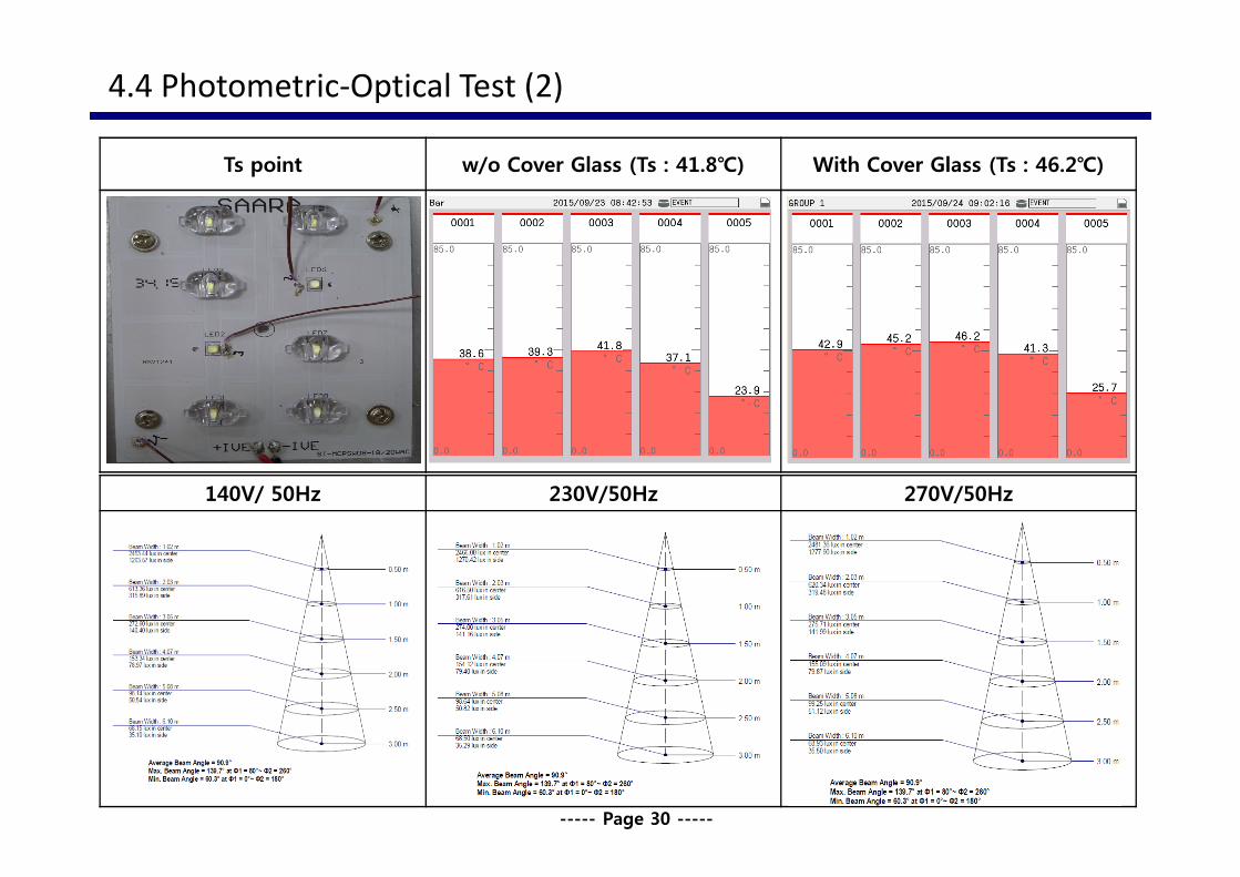
4.4 Photometric-Optical Test (2)
Ts point w/o Cover Glass (Ts : 41.8℃) With Cover Glass (Ts : 46.2℃)
----- Page 30 -----
140V/ 50Hz 230V/50Hz 270V/50Hz
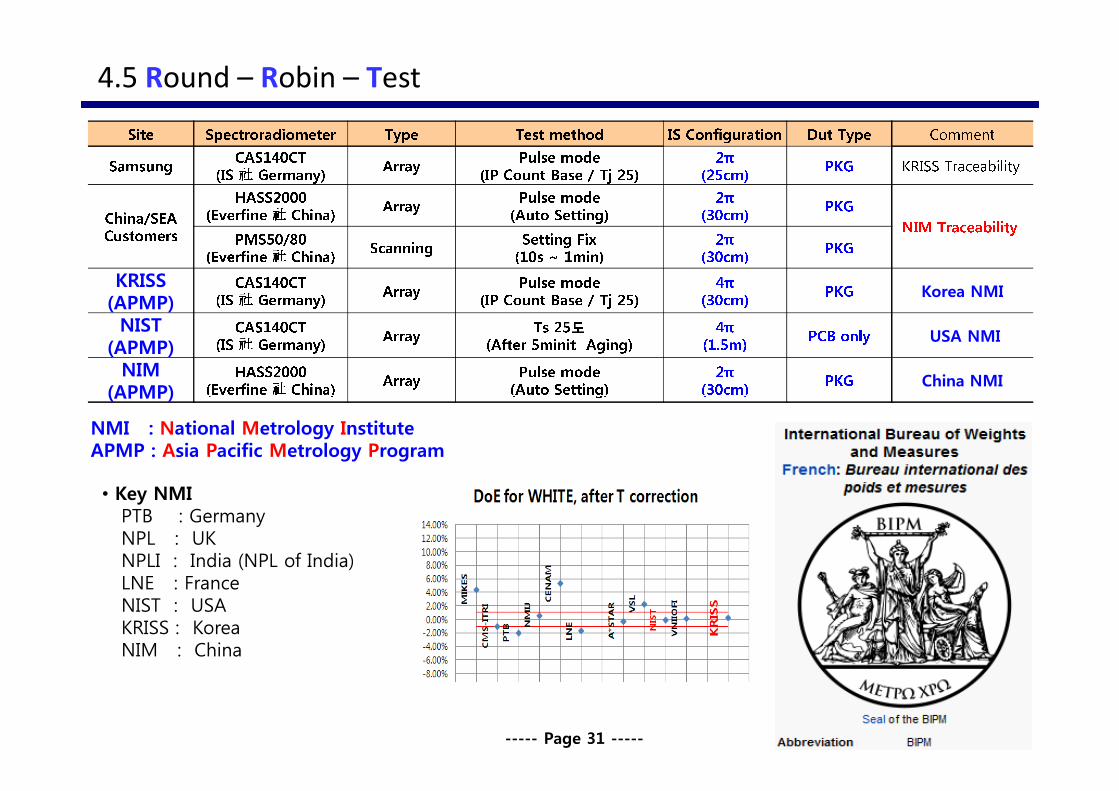
4.5 Round – Robin – TestSite Spectroradiometer Type Test method IS Configuration Dut Type CommentSamsung CAS140CT(IS 社社社社 Germany) Array Pulse mode(IP Count Base / Tj 25) 2π (25cm) PKG KRISS TraceabilityChina/SEA Customers HASS2000(Everfine 社社社社 China) Array Pulse mode(Auto Setting) 2π(30cm) PKG NIM TraceabilityPMS50/80(Everfine 社社社社 China) Scanning Setting Fix(10s ~ 1min) 2π(30cm) PKGKRISS(APMP)
CAS140CT(IS 社社社社 Germany) Array Pulse mode(IP Count Base / Tj 25) 4π(30cm) PKG Korea NMINIST
(APMP)CAS140CT(IS 社社社社 Germany) Array Ts 25도(After 5minit Aging) 4π(1.5m) PCB only USA NMI
NIM(APMP)
HASS2000(Everfine 社社社社 China) Array Pulse mode(Auto Setting) 2π(30cm) PKG China NMI
----- Page 31 -----
(APMP) (Everfine 社社社社 China) (Auto Setting) (30cm)• Key NMI PTB : GermanyNPL : UKNPLI : India (NPL of India) LNE : FranceNIST : USAKRISS : KoreaNIM : China
NMI : National Metrology InstituteAPMP : Asia Pacific Metrology Program

* Integral Platform Modular Platform
Appendix 1 SSL Configuration (1)
----- Page 32 -----
Integral Platform : Model by Model Series Configuration : 36 Series ,52 Series, 78 Series Parallel Strings Configuration : 15S8P , 12S10PMatrix Configuration ) : 10S3P , 11S4P
Modular Platform : For Mass CustomizationSeries Configuration : 54Series (18*3) , 72 Series (18* 4)Multi-Channel : 18 Series * 3P~7P Parallel String Configuration : 14 Series * 3P~6P , 18 Series * 3P ~ 4P
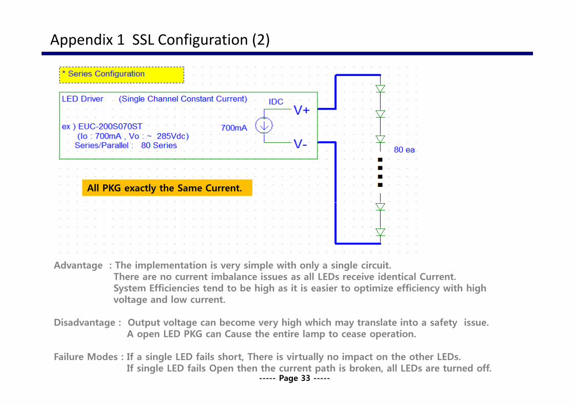
All PKG exactly the Same Current.
Appendix 1 SSL Configuration (2)
----- Page 33 -----
Advantage : The implementation is very simple with only a single circuit. There are no current imbalance issues as all LEDs receive identical Current.System Efficiencies tend to be high as it is easier to optimize efficiency with highvoltage and low current.
Disadvantage : Output voltage can become very high which may translate into a safety issue.A open LED PKG can Cause the entire lamp to cease operation.
Failure Modes : If a single LED fails short, There is virtually no impact on the other LEDs. If single LED fails Open then the current path is broken, all LEDs are turned off.

Current is divided between the Various Strings based on how well each of the strings are matched.
Appendix 1 SSL Configuration (3)
----- Page 34 -----
Advantage : Requires the use of only a single Driver and output voltage can be kept rather low. (Can be meet SELV- equivalent) By Vf Binning in Modular Design, reasonable Current sharing can be achieved among the paralleled LED Stings.
Disadvantage : 1. Vf Binning is impossible in Integral Design, So small differences in the Vf of the various LEDs can cause significant imbalances in current.
2. The improved accuracy of current sharing is achieved at the external Resistors, But in this case, increased power dissipation in the resistors.
3. Any Failure of an LED Open or Short circuit can Cause significant stress on the remaining LEDs. Failure Modes : If a single LED Fails short, the string in which the failed LED resides will take significantly
greater than its shared of the current. The stress on the LEDs in this string will increasesignificantly thus increasing the likelihood that a second LED will Fail.
matched.

The most Risk Configuration
Appendix 1 SSL Configuration (4)
----- Page 35 -----
Advantage : If one LED fails, The remaining LEDs still Operate.
Disadvantage : In the worst case the current distribution can be very unsymmetrical.Non-Uniform current sharing leads to non-uniform light and Thermal distribution in the SSL.
The most Robust Configuration
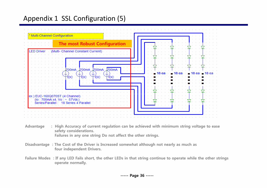
Appendix 1 SSL Configuration (5)
----- Page 36 -----
Advantage : High Accuracy of current regulation can be achieved with minimum string voltage to ease safety considerations. Failures in any one string Do not affect the other strings.
Disadvantage : The Cost of the Driver is Increased somewhat although not nearly as much as four independent Drivers.
Failure Modes : If any LED Fails short, the other LEDs in that string continue to operate while the other stringsoperate normally.
Revision History
Revision Data Page Description WriterRev. 1.0 2015-12-10 - First Edition LEE SAK
----- Page 37 -----
If you have any further questions , please contact :
LEE SAK (Isaac, 艾萨克艾萨克艾萨克艾萨克)
Office : (82)-(70)-7142-1388 , [email protected]
Mobile : (82)-(10)-9177-1225 , [email protected]
Recommended