Object Conveyance System "Magic Carpet"Consisting of 64 Linear Actuators - Object PositionFeedback Control with Object Position Estimation -
Hichirousai Oyobe and Yoichi Hori
Department of Electrical EngineeringUniversity of Tokyo
7-3-1 Hongo, Bunkyo, Tokyo 113-8656, [email protected], [email protected]
http://www.hori.t.u-tokyo.ac.jp/997/oyobe/index.html, www.hori.t.u-tokyo.ac.jp/staff/hori/index-j.html
Abstract|A novel object transfer system named "MagicCarpet" composed of linear actuator array and driven by au-tonomous decentralized type control algorithm is proposed.An object is manipulated by a large number of contactpoints with many actuators, which di�ers from conventionalsystems like belt conveyor. In this paper, the control algo-rithm for such "distributed manipulation" is proposed.
Due to recent development of micromachine technology,distributed manipulation becomes more important. Thissystem has a big advantage in its fault tolerance because ithas a lot of actuators with poor performance to move a largeheavy object. However, it has a serious wiring problem tobe solved and homogeneous structure should be introducedbecause of a large number actuators.To solve these problems, "combined control of central
/autonomous decentralized algorithms" is proposed and ef-fectiveness of proposed object position control algorithmbased on feedback is con�rmed by computer simulation. Torealize this feedback, the object position estimation algo-rithm is too proposed.
I. Introduction
There are various kinds of scheme to move objects. Ob-
ject transfer by belt conveyor and robot manipulator is
�rstly considered. Distributed manipulation e�ects an ob-
ject through a large number of contact points and ob-
ject transfer by this distributed manipulation scheme is
attempted in various �eld [1]. This manipulation is very
similar to transfer scheme by lifting someone into the air
by many persons and also has the following bene�ts:
1. fault-tolerant
2. large heavy object transfer by many small poor
actuators
This concept means not to get high performance by
only one actuator but to get high performance by small
simple many actuator cooperation. Due to the recent
development of MEMS(Micro Electro Mechanical Sys-
tem) [2], [3], [4], [5], 1 this concept becomes more feasible
to manufacture many actuators at low cost. The system
consisting of many actuators has not only above merits but
also some inherent problems as follows.
1. communication
To avoid large scale and complicated wiring problem
1MEMS is often characterized by miniaturization, multiplicity andmicroelectronics.
of communication network, it should be assumed that
the module can exchange information only with neigh-
boring several modules.
2. structure
The system is very suitable for homogeneous struc-
ture since the system composed of many actuators is
fundamentally promised.
Distributed manipulation research is performed by many
types of mechanisms at di�erent scales from micro-
scale [6], [7], [8], [9] to macro-scale [10], [11], [12]. Astro-
nomical telescope "Subaru" composed of very large optical
re ect mirror is well known as a great successful example
of distributed manipulation.
II. Proposal of "Magic Carpet" composed of
many actuators
For consideration of such distributed manipulation sys-
tem, we set an explicit problem. The problem is to move
an object put on the magic carpet to the target position.
Each module of the magic carpet shown in Fig.1 can move
along only z-direction [7].
Move an Object
(xini; yini)) (xd; yd)
where, (xini; yini) is the initial position of the object and
(xd; yd) is the target position.
We consider actuator array on the xy-plane (xmin � x �
xmax; ymin � y � ymax), which consists of m decentralized
modules along x-direction and n along y-direction [8]. The
function of each decentralized actuator module is given as
follows.
� sensor
The sensor detects whether anything exists on the
module or not.
� actuator
The actuator drives the module along z-direction and
keeps it at any position.
� microprocessor
The microprocessor can perform very simple calcula-
tion and communicate only with several neighboring
modules.
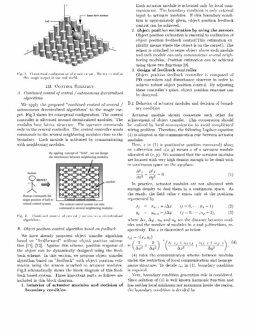
Fig. 1. Conceptual con�guration of magic carpet. We try to realizethis magic carpet in our real world.
III. Control Strategy
A. Combined control of central / autonomous decentralizedalgorithms
We apply the proposed "combined control of central /
autonomous decentralized algorithms" to the magic car-
pet. Fig.2 shows its conceptual con�guration. The central
controller is allocated around decentralized modules. The
modules have lattice structure. The operator commands
only to the central controller. The central controller sends
commands to the several neighboring modules close to the
boundary. Each module is activated by communicating
with neighboring modules.
Central control system
MOVE!
The central control system can only command to several neighboring modules .
human
By appling concept of "field" , we can design the interference between neighboring modules.
module
Human commands the target position of ball to central control system.
Fig. 2. Combined control of central / autonomous decentralizedalgorithms.
B. Object position control algorithm based on feedback
We have already proposed object transfer algorithm
based on "feedforward" without object position estima-
tion [11], [12]. Against this scheme, position response of
the object can be dynamically designed using the feed-
back scheme. In this section, we propose object transfer
algorithm based on "feedback" with object position esti-
mation using the sensors attached to actuator modules.
Fig.3 schematically shows the block diagram of this feed-
back based system. Three important parts as follows are
included in this block diagram.1. behavior of actuator modules and decision of
boundary condition
Each actuator module is activated only by local com-
munication. The boundary condition is only external
input to actuator modules. If this boundary condi-
tion is appropriately given, object position feedback
control can be achieved.
2. object position estimation by using the sensors
Object position estimation is essential to realization of
object position feedback control(This estimation ex-
plicitly means where the object is on the carpet). The
sensor is attached to sense object above each module
and each module can only communicate several neigh-
boring modules. Position estimation can be achieved
using those two functions [9].
3. design of feedback controller
Object position feedback controller is composed of
PD controllers and disturbance observer in order to
achieve robust object position control. By adjusting
these controller's gains, object position response can
be designed.
B.1 Behavior of actuator modules and decision of bound-
ary condition
Actuator module should cooperate each other for
achievement of object transfer. This cooperation should
be realized by local communication to avoid complicated
wiring problem. Therefore, the following Laplace equation
(1) is adopted as the communication rule between actuator
modules.
Here, z in (1) is position(or position command) along
to z-direction and z(x; y) means z of a actuator module
allocated at (x; y). We assumed that the actuator modules
are located with very high density enough to be dealt with
in continuous space on the xy-plane.
@2z
@x2+
@2z
@y2= 0 (1)
In practice, actuator modules are not allocated with
enough density to deal them in a continuous space. As
the result, the �eld value z exists only at the positions
represented by
xi = xmin + i�x (i = 0; � � � ; nx � 1) (2)
yj = ymin + j�y (j = 0; � � � ; ny � 1); (3)
where �x, �y , nx and ny are the distance between mod-
ules and the number of modules in x and y-directions, re-
spectively. The z is discretized as below.
zij = z(xi; yj)
=
�2
�x2+
2
�y2
��1�
zi�1;j + zi+1;j
�x2+zi;j�1 + zi;j+1
�y2
�:(4)
(4) rules the communication scheme between modules
under the restriction of local communication and homoge-
neous structure. To decide zij in (4), boundary condition
is required.
Next, boundary condition generation rule is considered.
Since solution of (1) is well known harmonic function and
has neither local minimum nor maximum inside the region,
the boundary condition is decided by

target position
oAAAAA
AAAAA
AAAAAAAAAAAA
AAAAAA
arrayed actuator modules
PD controller
disturbance obs.
generation of boundary condition
estimation of position
central control system
+-
+
-
y
x
(xd, y
d)
Fig. 3. Block diagram based on object position feedback control with object position estimation
� case1 (xobj � xd) > 0 & (yobj � yd) > 0
z(onBoundary3) = k(xobj � xd) ,
z(onBoundary1) = k(yobj � yd) ,
� case2 (xobj � xd) < 0 & (yobj � yd) > 0
z(onBoundary2) = k(xobj � xd) ,
z(onBoundary1) = k(yobj � yd) ,
� case3 (xobj � xd) > 0 & (yobj � yd) < 0
z(onBoundary3) = k(xobj � xd) ,
z(onBoundary4) = k(yobj � yd) ,
� case4 (xobj � xd) < 0 & (yobj � yd) < 0
z(onBoundary2) = k(xobj � xd) ,
z(onBoundary4) = k(yobj � yd) ,where k and (xobj ; yobj) are a positive constant and the
object current position, respectively. Surface curve of the
carpet generated by this boundary condition behaves like
a plate. The object on the carpet rolls over and over.
boundary
boundary 1
boundary 4
boun
dary
2
boun
dary
3
x
y
Fig. 4. Generation rules of the boundary condition
B.2 Object position estimation using the sensors
In this section, object position estimation by dis-
tributed scheme is considered. To move the object to the
target position, current position is necessary information.
By using the sensors, object position estimation can be
achieved. Poisson equation (5) is employed as the �eld
estimating the target position.
@2u
@x2+
@2u
@y2= f(x; y) (5)
Here, u in (5) is each module's internal state variable and
is numerically realized in each actuator module. Of course,
u(x; y) means u of a module at (x; y). The right term
f(x; y) of (5) is proportionally determined by the sensor
value at (x; y). If the variance of u(x; y) on the boundary is
monitored, the object position can be known. As is the case
with z in (1), u(x; y) is too discretized. Because actuator
modules are not allocated with enough density to deal them
in a continuous space.
B.3 Design of object position feedback controller
In the previous section, the boundary condition genera-
tion rules are already decided. Transfer function from the
boundary condition input to the actual object position ap-
proximately becomes double integral form like (6) ( The
dimension of the boundary condition input has same of
force.).
px
s2;
px =1 + 2(xmax � xmin)
2(xmax � xmin)2g
(6)
To this plant model (6), object position controller consist-
ing of PD controller and disturbance observer is attempted.
If the PD controller is described as
K(s) = k0 + sk1; (7)
the closed loop transfer function becomes
pxk0 + pxk1s
s2 + pxk1s+ pxk0
: (8)
If natural time constant �r and damping factor � of 2nd
order lag system are employed, the gains k0 and k1 are
described as
�2r =
1
pxk0
; 2��r =k1
k2
: (9)
To adjust these �r and �, characteristics of object position
response is freely designed.
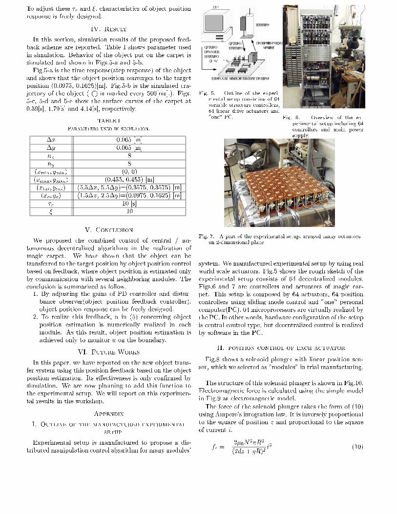
IV. Result
In this section, simulation results of the proposed feed-
back scheme are reported. Table I shows parameter used
in simulation. Behavior of the object put on the carpet is
simulated and shown in Figs.5-a and 5-b.
Fig.5-a is the time response(step response) of the object
and shows that the object position converges to the target
position (0.0975, 0.1625)[m]. Fig.5-b is the simulated tra-
jectory of the object ( is marked every 500[ms].). Figs.
5-c, 5-d and 5-e show the surface curves of the carpet at
0.59[s], 1.79[s] and 4.14[s], respectively.
TABLE I
Parameters used in simulation.
�x 0.065 [m]
�y 0.065 [m]
nx 8
ny 8
(xmin; ymin) (0, 0)
(xmax; ymax) (0.455, 0.455) [m]
(xini; yini) (5.5�x, 5.5�y)=(0.3575, 0.3575) [m]
(xc; yc) (1.5�x, 2.5�y)=(0.0975, 0.1625) [m]
�r 10 [s]
� 10
V. Conclusion
We proposed the combined control of central / au-
tonomous decentralized algorithms in the realization of
magic carpet. We have shown that the object can be
transferred to the target position by object position control
based on feedback, where object position is estimated only
by communication with several neighboring modules. The
conclusion is summarized as follow.1. By adjusting the gains of PD controller and distur-
bance observer(object position feedback controller),
object position response can be freely designed.
2. To realize this feedback, u in (5) concerning object
position estimation is numerically realized in each
module. As this result, object position estimation is
achieved only to monitor u on the boundary.
VI. Future Works
In this paper, we have reported on the new object trans-
fer system using this position feedback based on the object
position estimation. Its e�ectiveness is only con�rmed by
simulation. We are now planning to add this function to
the experimental setup. We will report on this experimen-
tal results in the workshop.
Appendix
I. Outline of the manufactured experimental
setup
Experimental setup is manufactured to propose a dis-
tributed manipulation control algorithm for many modules'
actuator×64
PC×1
driver with variable structure control × 64
position command & detection(64ch.DA &AD)
controller output (voltage)
position detection
Fig. 5. Outline of the experi-mental setup consisting of 64variable structure controllers,64 linear drive actuators and"one" PC. Fig. 6. Overview of the ex-
perimental setup including 64controllers and main powersupply.
Fig. 7. A part of the experimental setup, arrayed many actuatorson 2-dimensional plane
system. We manufactured experimental setup by using real
world scale actuators. Fig.5 shows the rough sketch of the
experimental setup consists of 64 decentralized modules.
Figs.6 and 7 are controllers and actuators of magic car-
pet. This setup is composed by 64 actuators, 64 position
controllers using sliding mode control and "one" personal
computer(PC). 64 microprocessors are virtually realized by
the PC. In other words, hardware con�guration of the setup
is central control type, but decentralized control is realized
by software in the PC.
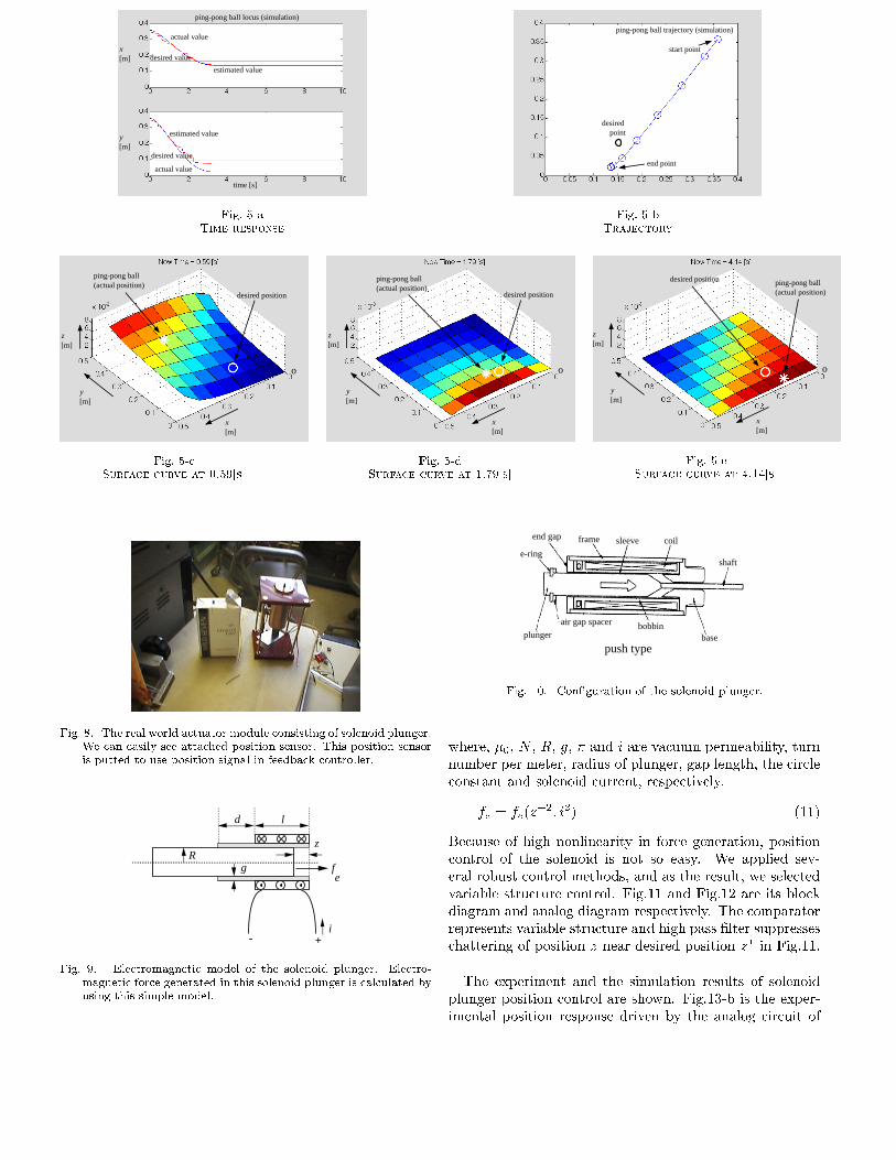
II. position control of each actuator
Fig.8 shows a solenoid plunger with linear position sen-
sor, which we selected as "modules" in trial manufacturing.
The structure of this solenoid plunger is shown in Fig.10.
Electromagnetic force is calculated using the simple model
in Fig.9 as electromagnetic model.
The force of the solenoid plunger takes the form of (10)
using Ampere's integration law. It is inversely proportional
to the square of position z and proportional to the square
of current i.
fe = �2�0N
2�R
2
(2dz + gR)2i2 (10)
ping-pong ball locus (simulation)
time [s]
x [m]
y [m]
desired value
actual value
desired value
actual value
estimated value
estimated value
Fig. 5-aTime response
ping-pong ball trajectory (simulation)
start point
end point
desired point
Fig. 5-bTrajectory
ping-pong ball(actual position)
desired position
x [m]
y [m]
z [m]
o
Fig. 5-cSurface curve at 0.59[s]
ping-pong ball(actual position)
desired position
x [m]
y [m]
z [m]
o
Fig. 5-dSurface curve at 1.79[s]
ping-pong ball(actual position)
desired position
x [m]
y [m]
z [m]
o
Fig. 5-eSurface curve at 4.14[s]
Fig. 8. The real world actuator module consisting of solenoid plunger.We can easily see attached position sensor. This position sensoris putted to use position signal in feedback controller.
Rg
d l
z
fe
i+-
Fig. 9. Electromagnetic model of the solenoid plunger. Electro-magnetic force generated in this solenoid plunger is calculated byusing this simple model.
push typeplunger
air gap spacer
basebobbin
shaft
coilsleeveframeend gap
e-ring
Fig. 10. Con�guration of the solenoid plunger.
where, �0, N , R, g, � and i are vacuum permeability, turn
number per meter, radius of plunger, gap length, the circle
constant and solenoid current, respectively.
fe = fe(z�2; i2) (11)
Because of high nonlinearity in force generation, position
control of the solenoid is not so easy. We applied sev-
eral robust control methods, and as the result, we selected
variable structure control. Fig.11 and Fig.12 are its block
diagram and analog diagram respectively. The comparator
represents variable structure and high pass �lter suppresses
chattering of position z near desired position z� in Fig.11.
The experiment and the simulation results of solenoid
plunger position control are shown. Fig.13-b is the exper-
imental position response driven by the analog circuit of

z*comparator
+
-
comparator output
fe (z -2, i 2 )
z
i
k
1M s 2
HPF
z
z+-
High Pass Filter to supress chattering
near desired position z*
{ imax z* -z <0
0 z* -z >0
Fig. 11. Control system of solenoid plunger with variable structurecontroller.
-+
+30V
-+
-+
-+
+15V
-15V
2k
1k
1k
5k
470
200
3k
+30V
solenoid
LM319
300k
300k
47nF
1000pF
z*
z
2SC5200
Fig. 12. Analog circuit of the variable structure controller. This vari-able structure controller actually used in the experiment. 64 setsof this analog circuit are prepared for realization of magic carpet.This circuit is very simple and adopted for position controller.
Fig.12 and Fig.13-a is the simulation results of position re-
sponse. Upper �gure in Fig.13-a is position response with-
out high pass �lter shown in Figs. 12 and 11 and Lower one
is with high pass �lter. We can see a good agreement be-
tween the command and actual positions and recognize to
overcome nonlinearity of the solenoid plunger and to sup-
press chattering near the command position by using ro-
bust variable structure (sliding mode) controller and high
pass �lter.
References
[1] K.-F.B�ohringer, Howie Choset, "Distributed Manipulation",Kluwer Academic Publishers
[2] Y. Nemoto, "On the Publication of an Issue on "Micro Machine",Jour. JSME, vol.97, no.905, pp.252, 1994 (in Japanese)
[3] Gabriel. K. J, "MEMS Research Project in U.S.A." , Jour.JSME, vol.97, no.905, pp.272-275, 1994 (in Japanese)
[4] H.Fujita, "Autonomous Distributed Systems for Microma-chines", Jour. SICE, vol.32, no.10, pp.848-853, 1993 (inJapanese)
[5] H.Fujita, "Autonomous Distributed Micro Systems", Jour.JSME, vol.97, pp.298-301, 1994 (in Japanese)
[6] S. Konishi, Y.Mita, H. Fujita, "Two-Dimensional ConveyanceSystem Using Cooperative Motions of Many Fluidic Microactu-ators", Jour. Advanced Robotics,vol.12, no.2, pp.155-165, 1998
[7] K.-F.B�ohringer, B.R.Donald, R.Mihailovich, N.C. MacDonald,"A Theory of Manipulation and Control for MicrofabricationActuator Arrays", In Proc. 7th IEEE International Workshopon Micro Electro Mechanical System, pp.102-107, 1994
[8] J.W.Suh, R.B.Darling, K.-F.B�ohringer, B.R.Donald, H.Bltes,T.A.Kovacs, "CMOS Integrated Ciliary Actuator Array asGeneral-Purpose Micromanipulation Tool for Small Objects",Journal of Microelectromechanical Systems, vol.8, no.4, pp.483-496, 1999
[9] K.-F.B�ohringer, V.Bhatt, K.Y.Goldberg, "Sensorless Manipula-tion Using Transverse Vibrations of a Plate", In Proc. the IEEE
without HPF
with HPF
time [s]
z [
m]
z [
m]
Fig. 13-aPosition response with variable structure
controller(simulation). Upper figure is without HPF andlower one is with HPF.
without HPF
with HPF
time [s]
z [
m]
z [
m]
Fig. 13-bPosition response with variable structure
controller(experiment).
Fig. 13. Position response with variable structure controller -
International Conference on Robotics nad Automation, pp.1989-1996, 1995
[10] J.Luntz, W. Messner, H.Choset, "Stick-Slip Operation of theModular Distributed Manipulator System", In Proc. AmericanControl Conference, pp.3853-3857, 1998
[11] H.Oyobe , H. Kitajima, Y.Hori, "Design and Realization of Au-tonomous Decentralized Object Transfer System:Magic Carpet",in Proc. 6th IEEE International Workshop on Advanced MotionControl, pp.25-29, 2000
[12] H.Oyobe, R. Marutani, Y.Hori, "Experimental Manufacturing ofObject Transfer System "Magic Carpet" Consisting of ActuatorArray with Autonomous Decentralized Control", in DistributedAutonomous Robotic System 4, Springer-Verlag, pp.437-446,2000
Recommended