Standard cylinders DNC, ISO 15552
Subject to change – 2011/082 � Internet: www.festo.com/catalog/...
Standard cylinders DNC, ISO 15552Key features
At a glance
DIN • Standards-based cylinders to
ISO 15552 (corresponds to the
withdrawn standards ISO 6431,
DIN ISO 6431, VDMA 24 562,
NF E 49 003.1 and UNI 10290)
• The modern design and
construction save up to 11% on
fitting space compared to ordinary
standard cylinders, thus permitting
a considerably more compact
system design
• An extensive range of accessories
makes it possible to install the
cylinder virtually anywhere
• The widest range of variants on the
market provides the right DNC
cylinder for every application
Cylinder with clamping units
DNC-KP DNCKE
• Piston rod can be held or clamped
in any position
• Piston rod can be held in position
for long periods even with
alternating loads, fluctuating
operating pressure or leaks in the
system
• Suitable for use in safety-related
control systems in compliance with
EN 954-1, EN 1050, EN 292 and
EN 983
• Fail-safe
• Piston rod can be clamped in any
position
Cylinder with end-position locking Cylinder/valve combination
DNC- … -EL DNC-V1 … V6
• Mechanical locking when the end
position is reached
• Lock is only automatically released
when pressure is supplied to the
cylinder
• End-position locking at one or both
ends
• The cylinder/valve combination is
assembled and fitted with tubing
ready for connection
• Particularly suitable for
decentralised use in larger systems
Tandem cylinder
DNCT
• Connection of 2 cylinders with the
same piston diameter and stroke in
series
• Double the thrust and return force
in comparison to a standard
cylinder
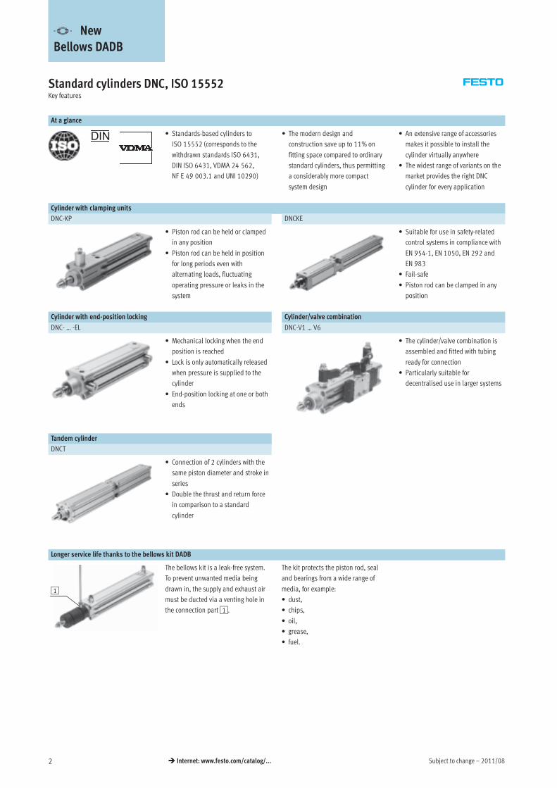
Longer service life thanks to the bellows kit DADB
1
The bellows kit is a leak-free system.
To prevent unwanted media being
drawn in, the supply and exhaust air
must be ducted via a venting hole in
the connection part1.
The kit protects the piston rod, seal
and bearings from a wide range of
media, for example:
• dust,
• chips,
• oil,
• grease,
• fuel.
-V- New
Bellows DADB
2011/08 – Subject to change 3� Internet: www.festo.com/catalog/...
Standard cylinders DNC, ISO 15552Key features
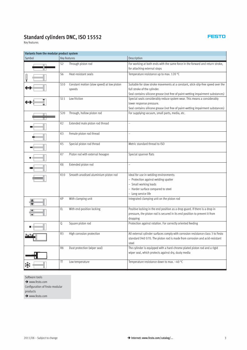
Variants from the modular product system
Symbol Key features Description
S2 Through piston rod For working at both ends with the same force in the forward and return stroke,
for attaching external stops
S6 Heat-resistant seals Temperature resistance up to max. 120 °C
S10 Constant motion (slow speed) at low piston
speeds
Suitable for slow stroke movements at a constant, stick-slip-free speed over the
full stroke of the cylinder.
Seal contains silicone grease (not free of paint-wetting impairment substances)
S11 Low friction Special seals considerably reduce system wear. This means a considerably
lower response pressure.
Seal contains silicone grease (not free of paint-wetting impairment substances)
S20 Through, hollow piston rod For supplying vacuum, small parts, media, etc.
K2 Extended male piston rod thread –
K3 Female piston rod thread –
K5 Special piston rod thread Metric standard thread to ISO
K7 Piston rod with external hexagon Special spanner flats
K8 Extended piston rod –
K10 Smooth anodised aluminium piston rod Ideal for use in welding environments:
– Protection against welding spatter
– Small working loads
– Harder surface compared to steel
– Long service life
KP With clamping unit Integrated clamping unit on the piston rod
EL With end-position locking Positive locking in the end position as a drop guard. If there is a drop in
pressure, the piston rod is secured in its end position to prevent it from
dropping
Q Square piston rod Protection against rotation. For correctly oriented feeding
R3 High corrosion protection All external cylinder surfaces comply with corrosion resistance class 3 to Festo
standard 940 070. The piston rod is made from corrosion and acid-resistant
steel
R8 Dust protection (wiper seal) The cylinder is equipped with a hard-chrome plated piston rod and a rigid
wiper seal, which protects against dry, dusty media
TT Low temperature Temperature resistance down to max. –40 °C
Software tools
� www.festo.com
Configuration of Festo modular
products
� www.festo.com
Subject to change – 2011/084 � Internet: www.festo.com/catalog/...
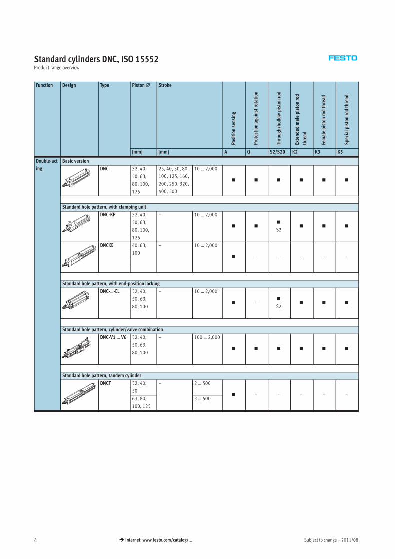
Standard cylinders DNC, ISO 15552Product range overview
Function Design Type Piston∅ Stroke
Position
sensing
Protection
againstrotation
Through/hollowpiston
rod
Extended
malepiston
rod
thread
Femalepiston
rodthread
Specialpiston
rodthread
[mm] [mm] A Q S2/S20 K2 K3 K5
Double-act
ing
Basic version
DNC 32, 40, 25, 40, 50, 80,
100, 125, 160,
200, 250, 320,
400, 500
10 … 2,000
� � � � � �50, 63,
80, 100,
125
Standard hole pattern, with clamping unit
DNC-KP 32, 40, – 10 … 2,000
� ��
S2� � �
50, 63,
80, 100,
125
DNCKE 40, 63, – 10 … 2,000
� – – – – –100
Standard hole pattern, with end-position locking
DNC-…-EL 32, 40, – 10 … 2,000
� –�
S2� � �
50, 63,
80, 100
Standard hole pattern, cylinder/valve combination
DNC-V1 … V6 32, 40, – 100 … 2,000
� � � � � �50, 63,
80, 100
Standard hole pattern, tandem cylinder
DNCT 32, 40, – 2 … 500
� – – – – –50
63, 80, 3 … 500
100, 125
2011/08 – Subject to change 5� Internet: www.festo.com/catalog/...
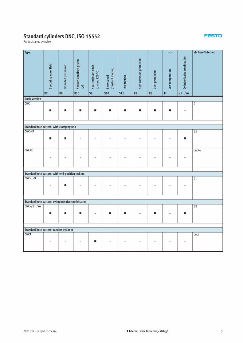
Standard cylinders DNC, ISO 15552Product range overview
Type -V- � Page/InternetSpecialspannerflats
Extended
piston
rod
Smooth
anodised
piston
rod
Heat-resistantseals
tomax.120°C
Slowspeed
(constantmotion)
Lowfriction
Highcorrosionprotection
Dustprotection
Lowtemperature
Cylinder/valvecombination
K7 K8 K10 S6 S10 S11 R3 R8 TT V1 … V6
Basic version
DNC
� � � � � � � � � –
9
Standard hole pattern, with clamping unit
DNC-KP
� � – – – – – – – �
23
DNCKE
– – – – – – – – – –
dncke
Standard hole pattern, with end-position locking
DNC-…-EL
– � – – – – – – – –
31
Standard hole pattern, cylinder/valve combination
DNC-V1 … V6
� � � – � � – � – �
38
Standard hole pattern, tandem cylinder
DNCT
– – – � – – – – – –
dnct
Subject to change – 2011/086 � Internet: www.festo.com/catalog/...
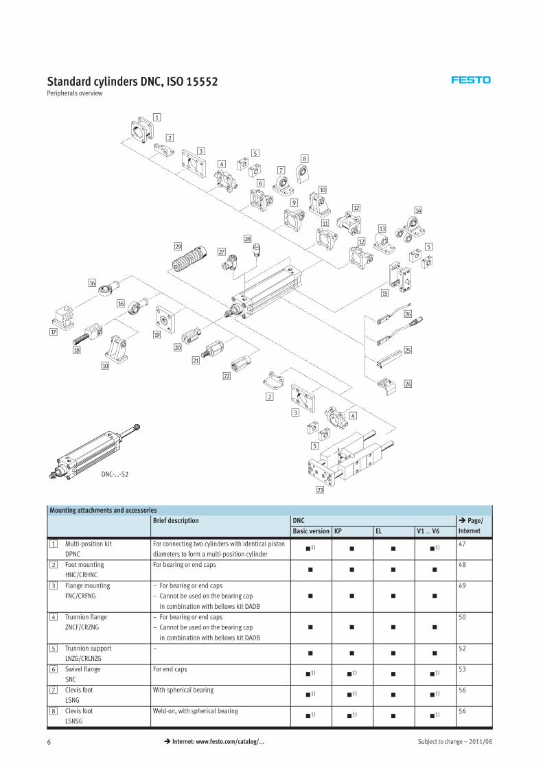
Standard cylinders DNC, ISO 15552Peripherals overview
1
2
3
4
5
6
7
8
9
aJ
aA
aB
aB
aC
aD
aE
aF
aF
aG
aH
aJ
aI
bJ
bA
bB
2
3 4
bC
bD
bE
bF
bG
bH
5
5
DNC-…-S2
bI
Mounting attachments and accessories
Brief description DNC � Page/
InternetBasic version KP EL V1 … V6
1 Multi-position kit
DPNC
For connecting two cylinders with identical piston
diameters to form a multi-position cylinder�1) � � �1)
47
2 Foot mounting
HNC/CRHNC
For bearing or end caps� � � �
48
3 Flange mounting
FNC/CRFNG
– For bearing or end caps
– Cannot be used on the bearing cap
in combination with bellows kit DADB
� � � �
49
4 Trunnion flange
ZNCF/CRZNG
– For bearing or end caps
– Cannot be used on the bearing cap
in combination with bellows kit DADB
� � � �
50
5 Trunnion support
LNZG/CRLNZG
–� � � �
52
6 Swivel flange
SNC
For end caps�1) �1) � �1)
53
7 Clevis foot
LSNG
With spherical bearing�1) �1) � �1)
56
8 Clevis foot
LSNSG
Weld-on, with spherical bearing�1) �1) � �1)
56
2011/08 – Subject to change 7� Internet: www.festo.com/catalog/...
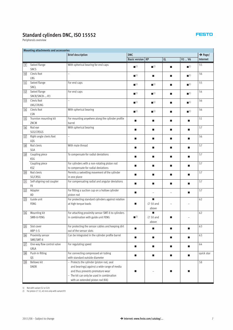
Standard cylinders DNC, ISO 15552Peripherals overview
Mounting attachments and accessories
Brief description DNC � Page/
InternetBasic version KP EL V1 … V6
9 Swivel flange
SNCS
With spherical bearing for end caps�1) �1) � �1)
55
aJ Clevis foot
LBG
–�1) � � �1)
56
aA Swivel flange
SNCL
For end caps�1) �1) � �1)
55
aB Swivel flange
SNCB/SNCB-…-R3
For end caps�1) �1) � �1)
54
aC Clevis foot
LNG/CRLNG
–�1) �1) � �1)
56
aD Clevis foot
LSN
With spherical bearing�1) �1) � �1)
56
aE Trunnion mounting kit
ZNCM
For mounting anywhere along the cylinder profile
barrel� � � �
51
aF Rod eye
SGS/CRSGS
With spherical bearing� � � �
57
aG Right-angle clevis foot
LQG
–� � � �
56
aH Rod clevis
SGA
With male thread� � � �
57
aI Coupling piece
KSG
To compensate for radial deviations� � � �
57
Coupling piece
KSZ
For cylinders with a non-rotating piston rod
to compensate for radial deviations� � � �
57
bJ Rod clevis
SG/CRSG
Permits a swivelling movement of the cylinder
in one plane� � � �
57
bA Self-aligning rod coupler
FK
For compensating radial and angular deviations� � � �
57
bB Adapter
AD
For fitting a suction cup on a hollow cylinder
piston rod� – – �
57
bC Guide unit
FENG
For protecting standard cylinders against rotation
at high torque loads �
�
∅ 50 and
above
– –
62
bD Mounting kit
SMB-8-FENG
For attaching proximity sensor SMT-8 to cylinders
in combination with guide unit FENG �2)
�
∅ 50 and
above
� –
62
bE Slot cover
ABP-5-S
For protecting the sensor cables and keeping dirt
out of the sensor slots� � � �
63
bF Proximity sensor
SME/SMT-8
Can be integrated in the cylinder profile barrel� � � �
63
bG One-way flow control valve
GRLA
For regulating speed� � � �
64
bH Push-in fitting
QS
For connecting compressed air tubing
with standard outside diameter� � � �
quick star
bI Bellows kit
DADB
– Protects the cylinder (piston rod, seal
and bearings) against a wide range of media
and thus prevents premature wear
– The kit can only be used in combination
with an extended piston rod (K8)
� – � �
58
1) Not with variant S2 or S20
2) For piston∅ 32, 40 mm only with variant R3
Subject to change – 2011/088 � Internet: www.festo.com/catalog/...
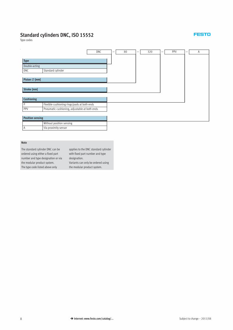
Standard cylinders DNC, ISO 15552Type codes
u
DNC — 80 — 320 — PPV — A
Type
Double-acting
DNC Standard cylinder
Piston∅ [mm]
Stroke [mm]
Cushioning
P Flexible cushioning rings/pads at both ends
PPV Pneumatic cushioning, adjustable at both ends
Position sensing
Without position sensing
A Via proximity sensor
Note
The standard cylinder DNC can be
ordered using either a fixed part
number and type designation or via
the modular product system.
The type code listed above only
applies to the DNC standard cylinder
with fixed part number and type
designation.
Variants can only be ordered using
the modular product system.
2011/08 – Subject to change 9� Internet: www.festo.com/catalog/...
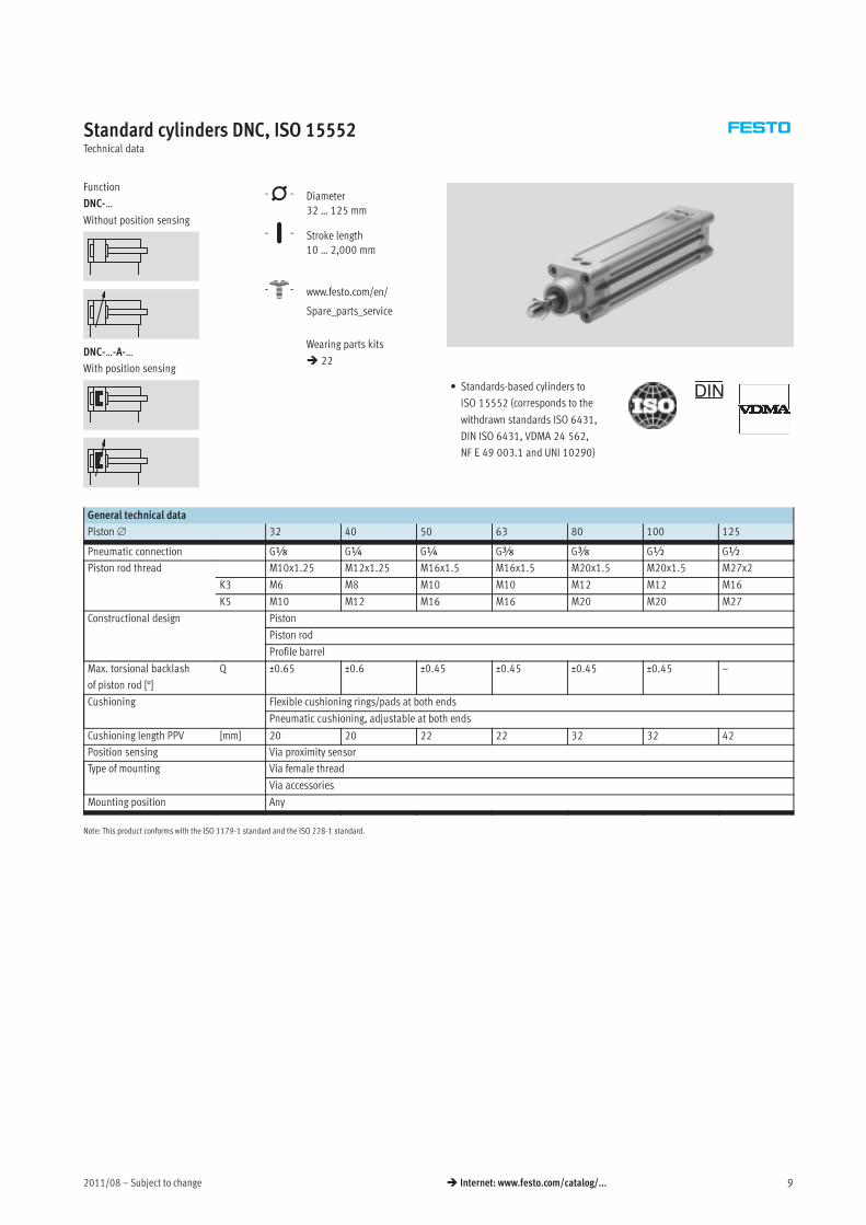
Standard cylinders DNC, ISO 15552Technical data
Function
DNC-…
Without position sensing
DNC-…-A-…
With position sensing
-N- Diameter
32 … 125 mm
-T- Stroke length
10 … 2,000 mm
-W- www.festo.com/en/
Spare_parts_service
Wearing parts kits
� 22
• Standards-based cylinders to
ISO 15552 (corresponds to the
withdrawn standards ISO 6431,
DIN ISO 6431, VDMA 24 562,
NF E 49 003.1 and UNI 10290)
DIN
General technical data
Piston∅ 32 40 50 63 80 100 125
Pneumatic connection Gx G¼ G¼ Gy Gy G½ G½
Piston rod thread M10x1.25 M12x1.25 M16x1.5 M16x1.5 M20x1.5 M20x1.5 M27x2
K3 M6 M8 M10 M10 M12 M12 M16
K5 M10 M12 M16 M16 M20 M20 M27
Constructional design Piston
Piston rod
Profile barrel
Max. torsional backlash
of piston rod [°]
Q ±0.65 ±0.6 ±0.45 ±0.45 ±0.45 ±0.45 –
Cushioning Flexible cushioning rings/pads at both ends
Pneumatic cushioning, adjustable at both ends
Cushioning length PPV [mm] 20 20 22 22 32 32 42
Position sensing Via proximity sensor
Type of mounting Via female thread
Via accessories
Mounting position Any
Note: This product conforms with the ISO 1179-1 standard and the ISO 228-1 standard.
Subject to change – 2011/0810 � Internet: www.festo.com/catalog/...
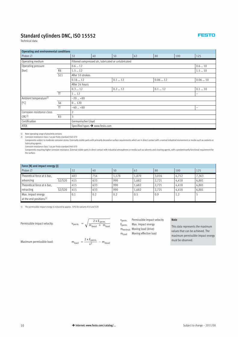
Standard cylinders DNC, ISO 15552Technical data
Operating and environmental conditions
Piston∅ 32 40 50 63 80 100 125
Operating medium Filtered compressed air, lubricated or unlubricated
Operating pressure
[bar]
0.6 … 12 0.6 … 10
R8 1.5 … 12 1.5 … 10
S11 After 10 strokes
0.16 … 12 0.1 … 12 0.06 … 12 0.06 … 10
After 24 hours
0.3 … 12 0.2 … 12 0.1 … 12 0.1 … 10
TT 1 … 12 –
Ambient temperature1)
[°C]
–20 … +80
S6 0 … 120
TT –40 … +80 –
Corrosion resistance class
CRC2)2
R3 3
Certification Germanischer Lloyd
ATEX Specified types� www.festo.com
1) Note operating range of proximity sensors
2) Corrosion resistance class 2 as per Festo standard 940 070
Components subject to moderate corrosion stress. Externally visible parts with primarily decorative surface requirements which are in direct contact with a normal industrial environment or media such as coolants or
lubricating agents.
Corrosion resistance class 3 as per Festo standard 940 070
Components requiring higher corrosion resistance. External visible parts in direct contact with industrial atmospheres or media such as solvents and cleaning agents, with a predominantly functional requirement for
the surface.
Force [N] and impact energy [J]
Piston∅ 32 40 50 63 80 100 125
Theoretical force at 6 bar,
advancing
483 754 1,178 1,870 3,016 4,712 7,363
S2/S20 415 633 990 1,682 2,721 4,418 6,881
Theoretical force at 6 bar,
retracting
415 633 990 1,682 2,721 4,418 6,881
S2/S20 415 633 990 1,682 2,721 4,418 6,881
Max. impact energy
at the end positions1)0.1 0.2 0.2 0.5 0.9 1.2 5
1) The permissible impact energy is reduced by approx. 10% for variants K10 and S20
vperm. =
2 x Eperm.
mdead + mload
�
mload =
2 x Eperm.
v2− mdeadMaximum permissible load:
Permissible impact velocity:vperm. Permissible impact velocity
Eperm. Max. impact energy
mIntrinsic Moving load (drive)
mLoad Moving effective load
Note
This data represents the maximum
values that can be achieved. The
maximum permissible impact energy
must be observed.
2011/08 – Subject to change 11� Internet: www.festo.com/catalog/...
Standard cylinders DNC, ISO 15552Technical data
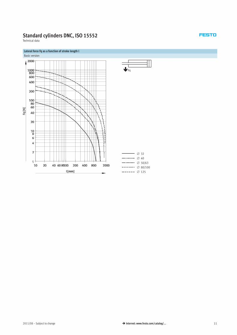
Lateral force Fq as a function of stroke length l
Basic version
∅ 32
∅ 40
∅ 50/63
∅ 80/100
∅ 125
Fq
Subject to change – 2011/0812 � Internet: www.festo.com/catalog/...
Standard cylinders DNC, ISO 15552Technical data
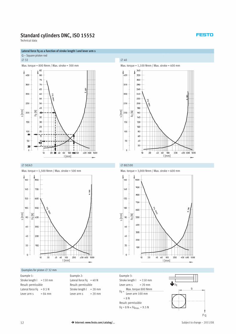
Lateral force Fq as a function of stroke length l and lever arm s
Q – Square piston rod
∅ 32 ∅ 40
Max. torque = 800 Nmm / Max. stroke = 300 mm Max. torque = 1,100 Nmm / Max. stroke = 400 mm
Fq[N]
s[mm]
l [mm] l [mm]
Fq[N]
s[mm]
∅ 50/63 ∅ 80/100
Max. torque = 1,500 Nmm / Max. stroke = 500 mm Max. torque = 3,000 Nmm / Max. stroke = 600 mm
Fq[N]
s[mm]
l [mm]
Fq[N]
s[mm]
l [mm]
Examples for piston∅ 32 mm
Example 1:
Stroke length l = 150 mm
Result: permissible
Lateral force Fq = 9.5 N
Lever arm s = 84 mm
Example 2:
Lateral force Fq = 40 N
Result: permissible
Stroke length l = 28 mm
Lever arm s = 20 mm
Example 3:
Stroke length l = 150 mm
Lever arm s = 20 mm
Result: permissible
Fq = 8 N < Fqmax. = 9.5 N
Fq =Max. torque 800 Nmm
Lever arm 100 mm
= 8 N
Fq
2011/08 – Subject to change 13� Internet: www.festo.com/catalog/...
Standard cylinders DNC, ISO 15552Technical data
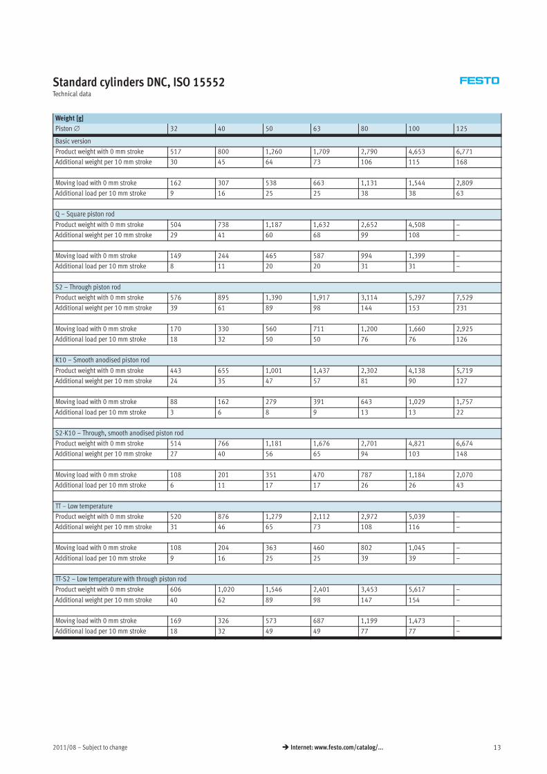
Weight [g]
Piston∅ 32 40 50 63 80 100 125
Basic version
Product weight with 0 mm stroke 517 800 1,260 1,709 2,790 4,653 6,771
Additional weight per 10 mm stroke 30 45 64 73 106 115 168
Moving load with 0 mm stroke 162 307 538 663 1,131 1,544 2,809
Additional load per 10 mm stroke 9 16 25 25 38 38 63
Q – Square piston rod
Product weight with 0 mm stroke 504 738 1,187 1,632 2,652 4,508 –
Additional weight per 10 mm stroke 29 41 60 68 99 108 –
Moving load with 0 mm stroke 149 244 465 587 994 1,399 –
Additional load per 10 mm stroke 8 11 20 20 31 31 –
S2 – Through piston rod
Product weight with 0 mm stroke 576 895 1,390 1,917 3,114 5,297 7,529
Additional weight per 10 mm stroke 39 61 89 98 144 153 231
Moving load with 0 mm stroke 170 330 560 711 1,200 1,660 2,925
Additional load per 10 mm stroke 18 32 50 50 76 76 126
K10 – Smooth anodised piston rod
Product weight with 0 mm stroke 443 655 1,001 1,437 2,302 4,138 5,719
Additional weight per 10 mm stroke 24 35 47 57 81 90 127
Moving load with 0 mm stroke 88 162 279 391 643 1,029 1,757
Additional load per 10 mm stroke 3 6 8 9 13 13 22
S2-K10 – Through, smooth anodised piston rod
Product weight with 0 mm stroke 514 766 1,181 1,676 2,701 4,821 6,674
Additional weight per 10 mm stroke 27 40 56 65 94 103 148
Moving load with 0 mm stroke 108 201 351 470 787 1,184 2,070
Additional load per 10 mm stroke 6 11 17 17 26 26 43
TT – Low temperature
Product weight with 0 mm stroke 520 876 1,279 2,112 2,972 5,039 –
Additional weight per 10 mm stroke 31 46 65 73 108 116 –
Moving load with 0 mm stroke 108 204 363 460 802 1,045 –
Additional load per 10 mm stroke 9 16 25 25 39 39 –
TT-S2 – Low temperature with through piston rod
Product weight with 0 mm stroke 606 1,020 1,546 2,401 3,453 5,617 –
Additional weight per 10 mm stroke 40 62 89 98 147 154 –
Moving load with 0 mm stroke 169 326 573 687 1,199 1,473 –
Additional load per 10 mm stroke 18 32 49 49 77 77 –
Subject to change – 2011/0814 � Internet: www.festo.com/catalog/...
Standard cylinders DNC, ISO 15552Technical data
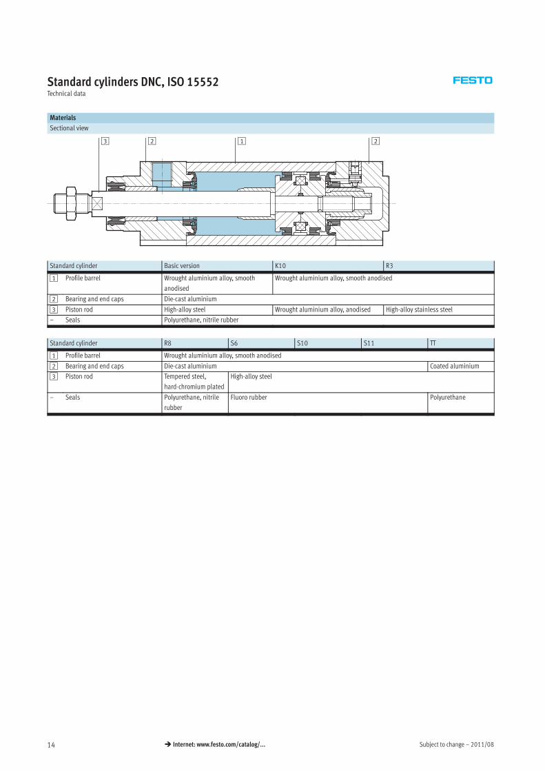
Materials
Sectional view
2123
Standard cylinder Basic version K10 R3
1 Profile barrel Wrought aluminium alloy, smooth
anodised
Wrought aluminium alloy, smooth anodised
2 Bearing and end caps Die-cast aluminium
3 Piston rod High-alloy steel Wrought aluminium alloy, anodised High-alloy stainless steel
– Seals Polyurethane, nitrile rubber
Standard cylinder R8 S6 S10 S11 TT
1 Profile barrel Wrought aluminium alloy, smooth anodised
2 Bearing and end caps Die-cast aluminium Coated aluminium
3 Piston rod Tempered steel,
hard-chromium plated
High-alloy steel
– Seals Polyurethane, nitrile
rubber
Fluoro rubber Polyurethane
2011/08 – Subject to change 15� Internet: www.festo.com/catalog/...
Standard cylinders DNC, ISO 15552Technical data
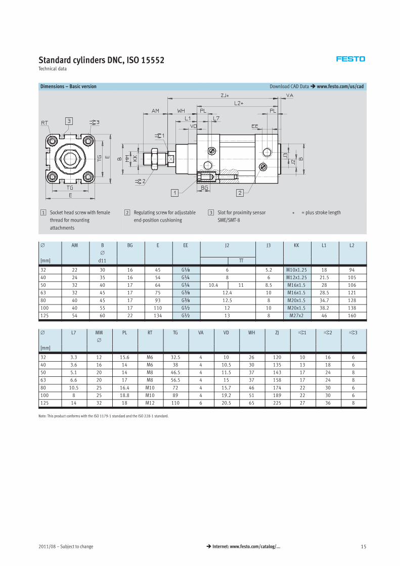
Dimensions – Basic version Download CAD Data� www.festo.com/us/cad
1 Socket head screw with female
thread for mounting
attachments
2 Regulating screw for adjustable
end-position cushioning
3 Slot for proximity sensor
SME/SMT-8
+ = plus stroke length
∅ AM B
∅
BG E EE J2 J3 KK L1 L2
[mm] d11 TT
32 22 30 16 45 Gx 6 5.2 M10x1.25 18 94
40 24 35 16 54 G¼ 8 6 M12x1.25 21.5 105
50 32 40 17 64 G¼ 10.4 11 8.5 M16x1.5 28 106
63 32 45 17 75 Gy 12.4 10 M16x1.5 28.5 121
80 40 45 17 93 Gy 12.5 8 M20x1.5 34.7 128
100 40 55 17 110 G½ 12 10 M20x1.5 38.2 138
125 54 60 22 134 G½ 13 8 M27x2 46 160
∅ L7 MM
∅
PL RT TG VA VD WH ZJ ß1 ß2 ß3
[mm]
32 3.3 12 15.6 M6 32.5 4 10 26 120 10 16 6
40 3.6 16 14 M6 38 4 10.5 30 135 13 18 6
50 5.1 20 14 M8 46.5 4 11.5 37 143 17 24 8
63 6.6 20 17 M8 56.5 4 15 37 158 17 24 8
80 10.5 25 16.4 M10 72 4 15.7 46 174 22 30 6
100 8 25 18.8 M10 89 4 19.2 51 189 22 30 6
125 14 32 18 M12 110 6 20.5 65 225 27 36 8
Note: This product conforms with the ISO 1179-1 standard and the ISO 228-1 standard.
Subject to change – 2011/0816 � Internet: www.festo.com/catalog/...
Standard cylinders DNC, ISO 15552Technical data
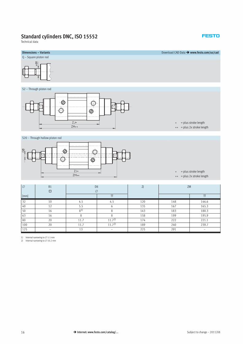
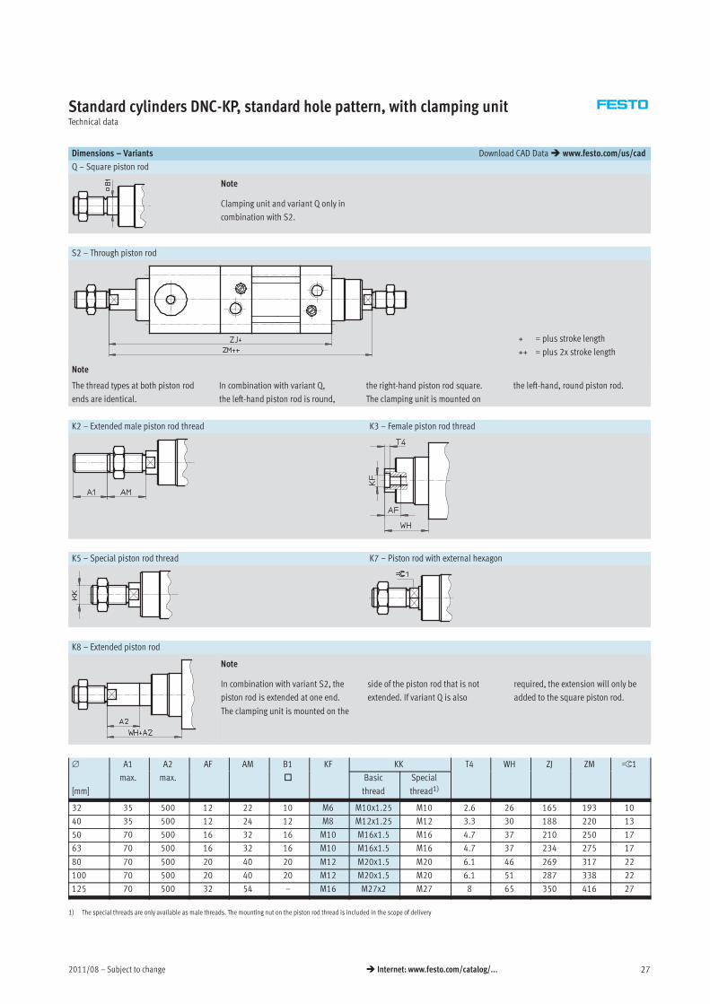
Dimensions – Variants Download CAD Data� www.festo.com/us/cad
Q – Square piston rod
S2 – Through piston rod
+ = plus stroke length
++ = plus 2x stroke length
S20 – Through hollow piston rod
+ = plus stroke length
++ = plus 2x stroke length
∅ B1
�
D8
∅
ZJ ZM
[mm] TT TT
32 10 4.5 4.5 120 148 146.6
40 12 5.5 6 135 167 165.3
50 16 81) 8 143 183 180.3
63 16 8 8 158 199 195.9
80 20 11.7 11.72) 174 222 221.1
100 20 11.7 11.72) 189 240 239.7
125 – 13 – 225 291 –
1) Internal narrowing to∅ 5.5 mm
2) Internal narrowing to∅ 10.2 mm
2011/08 – Subject to change 17� Internet: www.festo.com/catalog/...
Standard cylinders DNC, ISO 15552Technical data
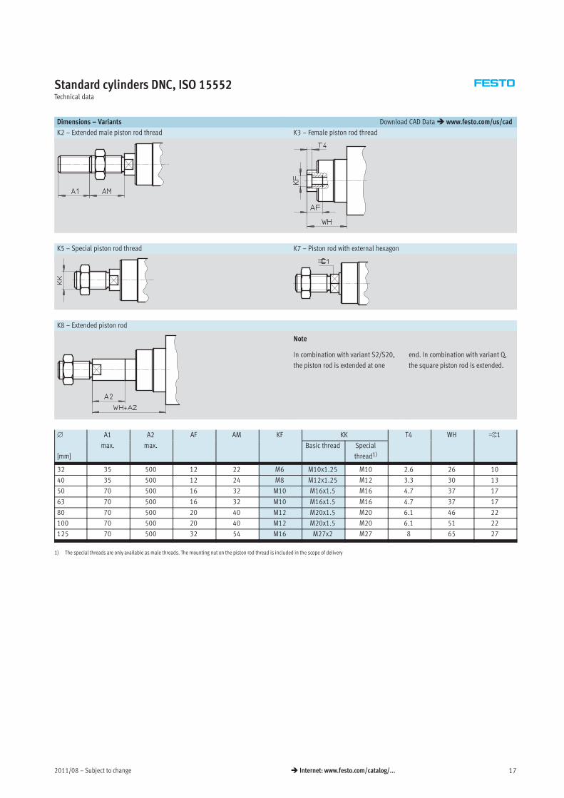
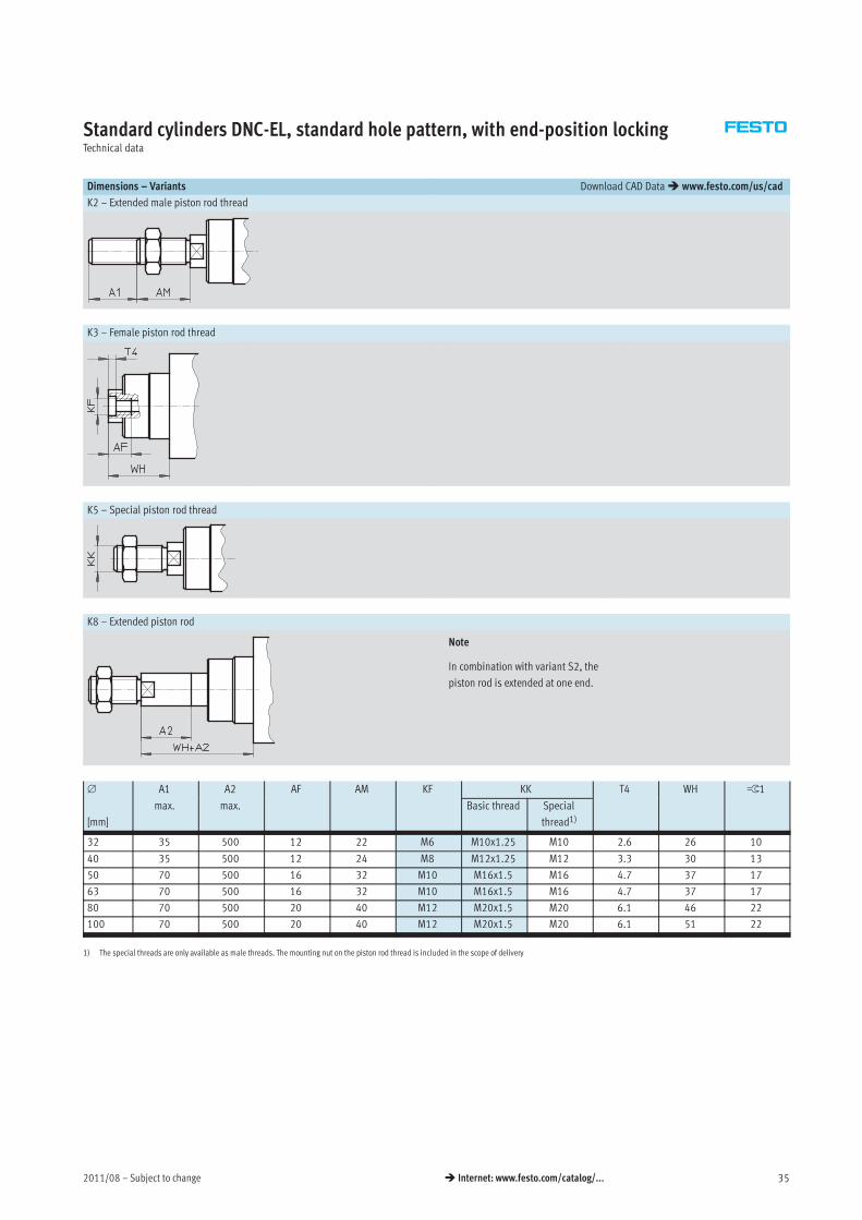
Dimensions – Variants Download CAD Data� www.festo.com/us/cad
K2 – Extended male piston rod thread K3 – Female piston rod thread
K5 – Special piston rod thread K7 – Piston rod with external hexagon
K8 – Extended piston rod
Note
In combination with variant S2/S20,
the piston rod is extended at one
end. In combination with variant Q,
the square piston rod is extended.
∅ A1 A2 AF AM KF KK T4 WH ß1
[mm]
max. max. Basic thread Special
thread1)
32 35 500 12 22 M6 M10x1.25 M10 2.6 26 10
40 35 500 12 24 M8 M12x1.25 M12 3.3 30 13
50 70 500 16 32 M10 M16x1.5 M16 4.7 37 17
63 70 500 16 32 M10 M16x1.5 M16 4.7 37 17
80 70 500 20 40 M12 M20x1.5 M20 6.1 46 22
100 70 500 20 40 M12 M20x1.5 M20 6.1 51 22
125 70 500 32 54 M16 M27x2 M27 8 65 27
1) The special threads are only available as male threads. The mounting nut on the piston rod thread is included in the scope of delivery
Subject to change – 2011/0818 � Internet: www.festo.com/catalog/...
Standard cylinders DNC, ISO 15552Technical data
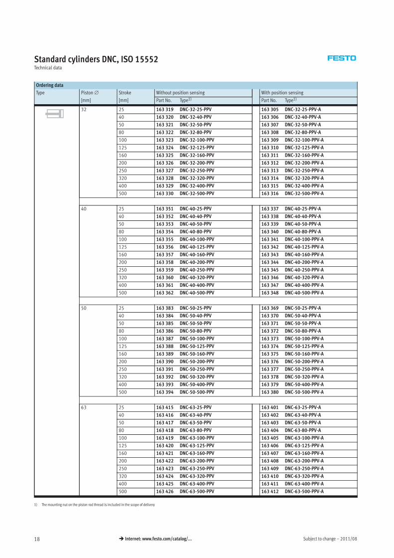
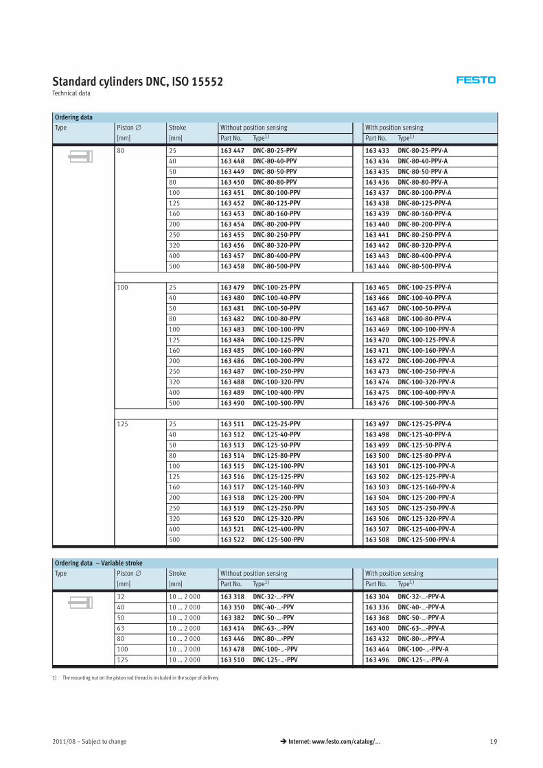
Ordering data
Type Piston∅ Stroke Without position sensing With position sensing
[mm] [mm] Part No. Type1) Part No. Type1)
32 25 163 319 DNC-32-25-PPV 163 305 DNC-32-25-PPV-A
40 163 320 DNC-32-40-PPV 163 306 DNC-32-40-PPV-A
50 163 321 DNC-32-50-PPV 163 307 DNC-32-50-PPV-A
80 163 322 DNC-32-80-PPV 163 308 DNC-32-80-PPV-A
100 163 323 DNC-32-100-PPV 163 309 DNC-32-100-PPV-A
125 163 324 DNC-32-125-PPV 163 310 DNC-32-125-PPV-A
160 163 325 DNC-32-160-PPV 163 311 DNC-32-160-PPV-A
200 163 326 DNC-32-200-PPV 163 312 DNC-32-200-PPV-A
250 163 327 DNC-32-250-PPV 163 313 DNC-32-250-PPV-A
320 163 328 DNC-32-320-PPV 163 314 DNC-32-320-PPV-A
400 163 329 DNC-32-400-PPV 163 315 DNC-32-400-PPV-A
500 163 330 DNC-32-500-PPV 163 316 DNC-32-500-PPV-A
40 25 163 351 DNC-40-25-PPV 163 337 DNC-40-25-PPV-A
40 163 352 DNC-40-40-PPV 163 338 DNC-40-40-PPV-A
50 163 353 DNC-40-50-PPV 163 339 DNC-40-50-PPV-A
80 163 354 DNC-40-80-PPV 163 340 DNC-40-80-PPV-A
100 163 355 DNC-40-100-PPV 163 341 DNC-40-100-PPV-A
125 163 356 DNC-40-125-PPV 163 342 DNC-40-125-PPV-A
160 163 357 DNC-40-160-PPV 163 343 DNC-40-160-PPV-A
200 163 358 DNC-40-200-PPV 163 344 DNC-40-200-PPV-A
250 163 359 DNC-40-250-PPV 163 345 DNC-40-250-PPV-A
320 163 360 DNC-40-320-PPV 163 346 DNC-40-320-PPV-A
400 163 361 DNC-40-400-PPV 163 347 DNC-40-400-PPV-A
500 163 362 DNC-40-500-PPV 163 348 DNC-40-500-PPV-A
50 25 163 383 DNC-50-25-PPV 163 369 DNC-50-25-PPV-A
40 163 384 DNC-50-40-PPV 163 370 DNC-50-40-PPV-A
50 163 385 DNC-50-50-PPV 163 371 DNC-50-50-PPV-A
80 163 386 DNC-50-80-PPV 163 372 DNC-50-80-PPV-A
100 163 387 DNC-50-100-PPV 163 373 DNC-50-100-PPV-A
125 163 388 DNC-50-125-PPV 163 374 DNC-50-125-PPV-A
160 163 389 DNC-50-160-PPV 163 375 DNC-50-160-PPV-A
200 163 390 DNC-50-200-PPV 163 376 DNC-50-200-PPV-A
250 163 391 DNC-50-250-PPV 163 377 DNC-50-250-PPV-A
320 163 392 DNC-50-320-PPV 163 378 DNC-50-320-PPV-A
400 163 393 DNC-50-400-PPV 163 379 DNC-50-400-PPV-A
500 163 394 DNC-50-500-PPV 163 380 DNC-50-500-PPV-A
63 25 163 415 DNC-63-25-PPV 163 401 DNC-63-25-PPV-A
40 163 416 DNC-63-40-PPV 163 402 DNC-63-40-PPV-A
50 163 417 DNC-63-50-PPV 163 403 DNC-63-50-PPV-A
80 163 418 DNC-63-80-PPV 163 404 DNC-63-80-PPV-A
100 163 419 DNC-63-100-PPV 163 405 DNC-63-100-PPV-A
125 163 420 DNC-63-125-PPV 163 406 DNC-63-125-PPV-A
160 163 421 DNC-63-160-PPV 163 407 DNC-63-160-PPV-A
200 163 422 DNC-63-200-PPV 163 408 DNC-63-200-PPV-A
250 163 423 DNC-63-250-PPV 163 409 DNC-63-250-PPV-A
320 163 424 DNC-63-320-PPV 163 410 DNC-63-320-PPV-A
400 163 425 DNC-63-400-PPV 163 411 DNC-63-400-PPV-A
500 163 426 DNC-63-500-PPV 163 412 DNC-63-500-PPV-A
1) The mounting nut on the piston rod thread is included in the scope of delivery
2011/08 – Subject to change 19� Internet: www.festo.com/catalog/...
Standard cylinders DNC, ISO 15552Technical data
Ordering data
Type Piston∅ Stroke Without position sensing With position sensing
[mm] [mm] Part No. Type1) Part No. Type1)
80 25 163 447 DNC-80-25-PPV 163 433 DNC-80-25-PPV-A
40 163 448 DNC-80-40-PPV 163 434 DNC-80-40-PPV-A
50 163 449 DNC-80-50-PPV 163 435 DNC-80-50-PPV-A
80 163 450 DNC-80-80-PPV 163 436 DNC-80-80-PPV-A
100 163 451 DNC-80-100-PPV 163 437 DNC-80-100-PPV-A
125 163 452 DNC-80-125-PPV 163 438 DNC-80-125-PPV-A
160 163 453 DNC-80-160-PPV 163 439 DNC-80-160-PPV-A
200 163 454 DNC-80-200-PPV 163 440 DNC-80-200-PPV-A
250 163 455 DNC-80-250-PPV 163 441 DNC-80-250-PPV-A
320 163 456 DNC-80-320-PPV 163 442 DNC-80-320-PPV-A
400 163 457 DNC-80-400-PPV 163 443 DNC-80-400-PPV-A
500 163 458 DNC-80-500-PPV 163 444 DNC-80-500-PPV-A
100 25 163 479 DNC-100-25-PPV 163 465 DNC-100-25-PPV-A
40 163 480 DNC-100-40-PPV 163 466 DNC-100-40-PPV-A
50 163 481 DNC-100-50-PPV 163 467 DNC-100-50-PPV-A
80 163 482 DNC-100-80-PPV 163 468 DNC-100-80-PPV-A
100 163 483 DNC-100-100-PPV 163 469 DNC-100-100-PPV-A
125 163 484 DNC-100-125-PPV 163 470 DNC-100-125-PPV-A
160 163 485 DNC-100-160-PPV 163 471 DNC-100-160-PPV-A
200 163 486 DNC-100-200-PPV 163 472 DNC-100-200-PPV-A
250 163 487 DNC-100-250-PPV 163 473 DNC-100-250-PPV-A
320 163 488 DNC-100-320-PPV 163 474 DNC-100-320-PPV-A
400 163 489 DNC-100-400-PPV 163 475 DNC-100-400-PPV-A
500 163 490 DNC-100-500-PPV 163 476 DNC-100-500-PPV-A
125 25 163 511 DNC-125-25-PPV 163 497 DNC-125-25-PPV-A
40 163 512 DNC-125-40-PPV 163 498 DNC-125-40-PPV-A
50 163 513 DNC-125-50-PPV 163 499 DNC-125-50-PPV-A
80 163 514 DNC-125-80-PPV 163 500 DNC-125-80-PPV-A
100 163 515 DNC-125-100-PPV 163 501 DNC-125-100-PPV-A
125 163 516 DNC-125-125-PPV 163 502 DNC-125-125-PPV-A
160 163 517 DNC-125-160-PPV 163 503 DNC-125-160-PPV-A
200 163 518 DNC-125-200-PPV 163 504 DNC-125-200-PPV-A
250 163 519 DNC-125-250-PPV 163 505 DNC-125-250-PPV-A
320 163 520 DNC-125-320-PPV 163 506 DNC-125-320-PPV-A
400 163 521 DNC-125-400-PPV 163 507 DNC-125-400-PPV-A
500 163 522 DNC-125-500-PPV 163 508 DNC-125-500-PPV-A
Ordering data – Variable stroke
Type Piston∅ Stroke Without position sensing With position sensing
[mm] [mm] Part No. Type1) Part No. Type1)
32 10 … 2 000 163 318 DNC-32-…-PPV 163 304 DNC-32-…-PPV-A
40 10 … 2 000 163 350 DNC-40-…-PPV 163 336 DNC-40-…-PPV-A
50 10 … 2 000 163 382 DNC-50-…-PPV 163 368 DNC-50-…-PPV-A
63 10 … 2 000 163 414 DNC-63-…-PPV 163 400 DNC-63-…-PPV-A
80 10 … 2 000 163 446 DNC-80-…-PPV 163 432 DNC-80-…-PPV-A
100 10 … 2 000 163 478 DNC-100-…-PPV 163 464 DNC-100-…-PPV-A
125 10 … 2 000 163 510 DNC-125-…-PPV 163 496 DNC-125-…-PPV-A
1) The mounting nut on the piston rod thread is included in the scope of delivery
Subject to change – 2011/0820 � Internet: www.festo.com/catalog/...
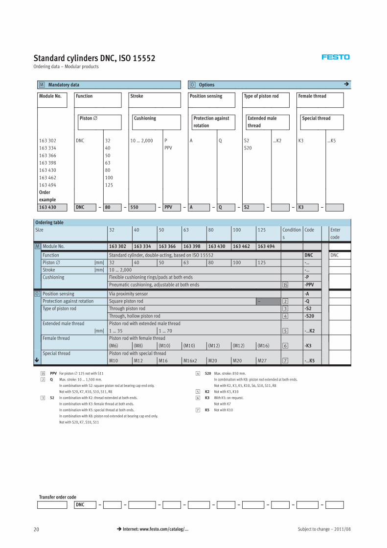
Standard cylinders DNC, ISO 15552Ordering data – Modular products
Mandatory data0M Options0O �
Module No. Function Stroke Position sensing Type of piston rod Female thread
Piston∅ Cushioning Protection against
rotation
Extended male
thread
Special thread
163 302
163 334
163 366
163 398
163 430
163 462
163 494
DNC 32
40
50
63
80
100
125
10 … 2,000 P
PPV
A Q S2
S20
…K2 K3 …K5
Order
example
163 430 DNC – 80 – 550 – PPV – A – Q – S2 – – K3 –
Ordering table
Size 32 40 50 63 80 100 125 Condition
s
Code Enter
code
0M Module No. 163 302 163 334 163 366 163 398 163 430 163 462 163 494
Function Standard cylinder, double-acting, based on ISO 15552 DNC DNC
Piston∅ [mm] 32 40 50 63 80 100 125 -…
Stroke [mm] 10 … 2,000 -…
Cushioning Flexible cushioning rings/pads at both ends -P
Pneumatic cushioning, adjustable at both ends aE -PPV
0O Position sensing Via proximity sensor -A
Protection against rotation Square piston rod – 2 -Q
Type of piston rod Through piston rod 3 -S2
Through, hollow piston rod 4 -S20
Extended male thread Piston rod with extended male thread
[mm] 1 … 35 1 … 70 5 -…K2
Female thread Piston rod with female thread
(M6) (M8) (M10) (M10) (M12) (M12) (M16) 6 -K3
Special thread Piston rod with special thread
� M10 M12 M16 M16x2 M20 M20 M27 7 -…K5
aE PPV For piston∅ 125 not with S11
2 Q Max. stroke: 10 … 1,500 mm.
In combination with S2: square piston rod at bearing cap end only.
Not with S20, K7, K10, S10, S11, R8
3 S2 In combination with K2: thread extended at both ends.
In combination with K3: female thread at both ends.
In combination with K5: special thread at both ends.
In combination with K8: piston rod extended at bearing cap end only.
Not with S20, K7, S10, S11
4 S20 Max. stroke: 850 mm.
In combination with K8: piston rod extended at both ends.
Not with K2, K3, K5, K10, S6, S10, S11, R8
5 K2 Not with K3, K10
6 K3 With K5: on request.
Not with K7
7 K5 Not with K10
Transfer order code
DNC – – – – – – – – –
2011/08 – Subject to change 21� Internet: www.festo.com/catalog/...
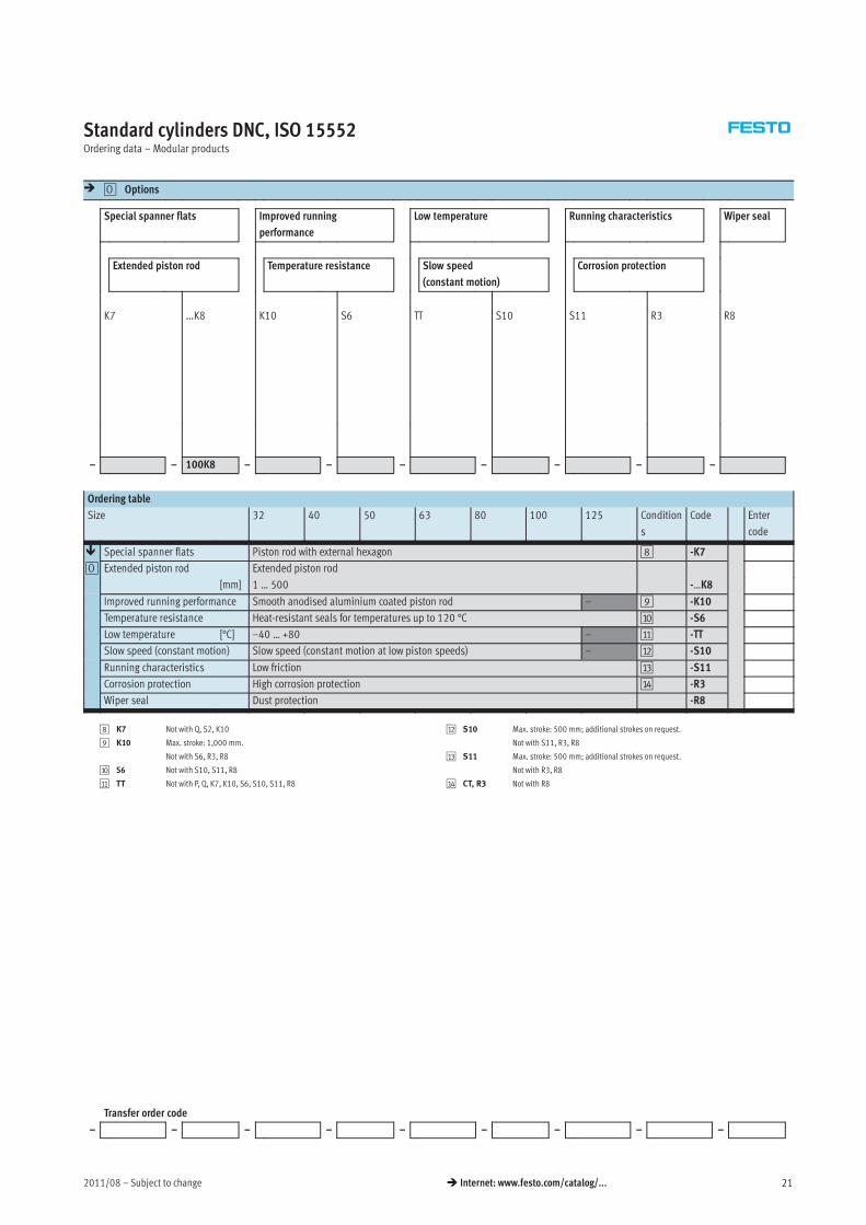
Standard cylinders DNC, ISO 15552Ordering data – Modular products
� Options0O
Special spanner flats Improved running
performance
Low temperature Running characteristics Wiper seal
Extended piston rod Temperature resistance Slow speed
(constant motion)
Corrosion protection
K7 …K8 K10 S6 TT S10 S11 R3 R8
– – 100K8 – – – – – – –
Ordering table
Size 32 40 50 63 80 100 125 Condition
s
Code Enter
code
� Special spanner flats Piston rod with external hexagon 8 -K7
0O Extended piston rod Extended piston rod
[mm] 1 … 500 -…K8
Improved running performance Smooth anodised aluminium coated piston rod – 9 -K10
Temperature resistance Heat-resistant seals for temperatures up to 120 °C aJ -S6
Low temperature [°C] –40 … +80 – aA -TT
Slow speed (constant motion) Slow speed (constant motion at low piston speeds) – aB -S10
Running characteristics Low friction aC -S11
Corrosion protection High corrosion protection aD -R3
Wiper seal Dust protection -R8
8 K7 Not with Q, S2, K10
9 K10 Max. stroke: 1,000 mm.
Not with S6, R3, R8
aJ S6 Not with S10, S11, R8
aA TT Not with P, Q, K7, K10, S6, S10, S11, R8
aB S10 Max. stroke: 500 mm; additional strokes on request.
Not with S11, R3, R8
aC S11 Max. stroke: 500 mm; additional strokes on request.
Not with R3, R8
aD CT, R3 Not with R8
Transfer order code
– – – – – – – – –
Subject to change – 2011/0822 � Internet: www.festo.com/catalog/...
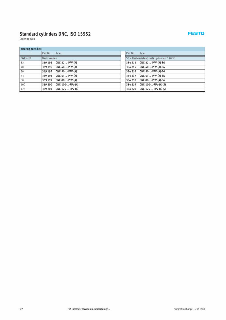
Standard cylinders DNC, ISO 15552Ordering data
Wearing parts kits
Part No. Type Part No. Type
Piston∅ Basic version S6 – Heat-resistant seals up to max. 120 °C
32 369 195 DNC-32-…-PPV-(A) 384 214 DNC-32-…-PPV-(A)-S6
40 369 196 DNC-40-…-PPV-(A) 384 215 DNC-40-…-PPV-(A)-S6
50 369 197 DNC-50-…-PPV-(A) 384 216 DNC-50-…-PPV-(A)-S6
63 369 198 DNC-63-…-PPV-(A) 384 217 DNC-63-…-PPV-(A)-S6
80 369 199 DNC-80-…-PPV-(A) 384 218 DNC-80-…-PPV-(A)-S6
100 369 200 DNC-100-…-PPV-(A) 384 219 DNC-100-…-PPV-(A)-S6
125 369 201 DNC-125-…-PPV-(A) 384 220 DNC-125-…-PPV-(A)-S6
2011/08 – Subject to change 23� Internet: www.festo.com/catalog/...
Standard cylinders DNC-KP, standard hole pattern, with clamping unitTechnical data
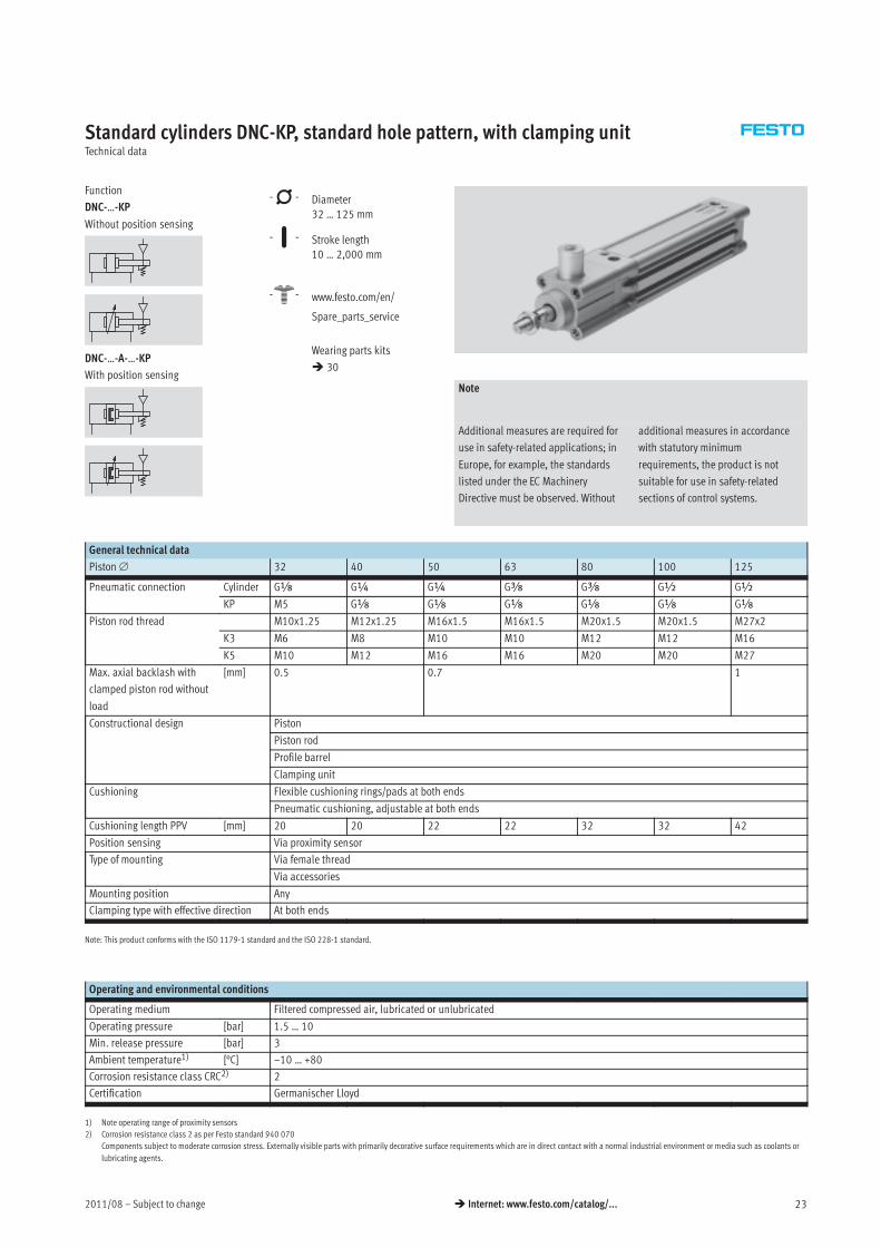
Function
DNC-…-KP
Without position sensing
DNC-…-A-…-KP
With position sensing
-N- Diameter
32 … 125 mm
-T- Stroke length
10 … 2,000 mm
-W- www.festo.com/en/
Spare_parts_service
Wearing parts kits
� 30
Note
Additional measures are required for
use in safety-related applications; in
Europe, for example, the standards
listed under the EC Machinery
Directive must be observed. Without
additional measures in accordance
with statutory minimum
requirements, the product is not
suitable for use in safety-related
sections of control systems.
General technical data
Piston∅ 32 40 50 63 80 100 125
Pneumatic connection Cylinder Gx G¼ G¼ Gy Gy G½ G½
KP M5 Gx Gx Gx Gx Gx Gx
Piston rod thread M10x1.25 M12x1.25 M16x1.5 M16x1.5 M20x1.5 M20x1.5 M27x2
K3 M6 M8 M10 M10 M12 M12 M16
K5 M10 M12 M16 M16 M20 M20 M27
Max. axial backlash with
clamped piston rod without
load
[mm] 0.5 0.7 1
Constructional design Piston
Piston rod
Profile barrel
Clamping unit
Cushioning Flexible cushioning rings/pads at both ends
Pneumatic cushioning, adjustable at both ends
Cushioning length PPV [mm] 20 20 22 22 32 32 42
Position sensing Via proximity sensor
Type of mounting Via female thread
Via accessories
Mounting position Any
Clamping type with effective direction At both ends
Note: This product conforms with the ISO 1179-1 standard and the ISO 228-1 standard.
Operating and environmental conditions
Operating medium Filtered compressed air, lubricated or unlubricated
Operating pressure [bar] 1.5 … 10
Min. release pressure [bar] 3
Ambient temperature1) [°C] –10 … +80
Corrosion resistance class CRC2) 2
Certification Germanischer Lloyd
1) Note operating range of proximity sensors
2) Corrosion resistance class 2 as per Festo standard 940 070
Components subject to moderate corrosion stress. Externally visible parts with primarily decorative surface requirements which are in direct contact with a normal industrial environment or media such as coolants or
lubricating agents.
Subject to change – 2011/0824 � Internet: www.festo.com/catalog/...
Standard cylinders DNC-KP, standard hole pattern, with clamping unitTechnical data
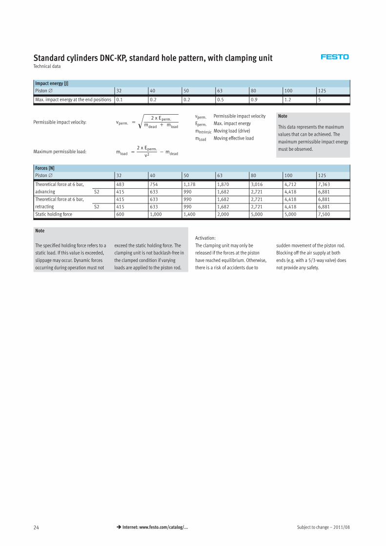
Impact energy [J]
Piston∅ 32 40 50 63 80 100 125
Max. impact energy at the end positions 0.1 0.2 0.2 0.5 0.9 1.2 5
vperm. =
2 x Eperm.
mdead + mload
�
mload =
2 x Eperm.
v2− mdeadMaximum permissible load:
Permissible impact velocity:vperm. Permissible impact velocity
Eperm. Max. impact energy
mIntrinsic Moving load (drive)
mLoad Moving effective load
Note
This data represents the maximum
values that can be achieved. The
maximum permissible impact energy
must be observed.
Forces [N]
Piston∅ 32 40 50 63 80 100 125
Theoretical force at 6 bar,
advancing
483 754 1,178 1,870 3,016 4,712 7,363
S2 415 633 990 1,682 2,721 4,418 6,881
Theoretical force at 6 bar,
retracting
415 633 990 1,682 2,721 4,418 6,881
S2 415 633 990 1,682 2,721 4,418 6,881
Static holding force 600 1,000 1,400 2,000 5,000 5,000 7,500
Note
Activation:
The specified holding force refers to a
static load. If this value is exceeded,
slippage may occur. Dynamic forces
occurring during operation must not
exceed the static holding force. The
clamping unit is not backlash-free in
the clamped condition if varying
loads are applied to the piston rod.
The clamping unit may only be
released if the forces at the piston
have reached equilibrium. Otherwise,
there is a risk of accidents due to
sudden movement of the piston rod.
Blocking off the air supply at both
ends (e.g. with a 5/3-way valve) does
not provide any safety.
2011/08 – Subject to change 25� Internet: www.festo.com/catalog/...
Standard cylinders DNC-KP, standard hole pattern, with clamping unitTechnical data
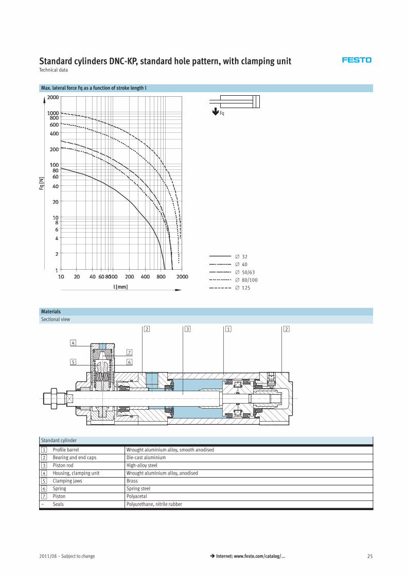
Max. lateral force Fq as a function of stroke length l
∅ 32
∅ 40
∅ 50/63
∅ 80/100
∅ 125
Fq
Materials
Sectional view
12 23
4
7
65
Standard cylinder
1 Profile barrel Wrought aluminium alloy, smooth anodised
2 Bearing and end caps Die-cast aluminium
3 Piston rod High-alloy steel
4 Housing, clamping unit Wrought aluminium alloy, anodised
5 Clamping jaws Brass
6 Spring Spring steel
7 Piston Polyacetal
– Seals Polyurethane, nitrile rubber
Subject to change – 2011/0826 � Internet: www.festo.com/catalog/...
Standard cylinders DNC-KP, standard hole pattern, with clamping unitTechnical data
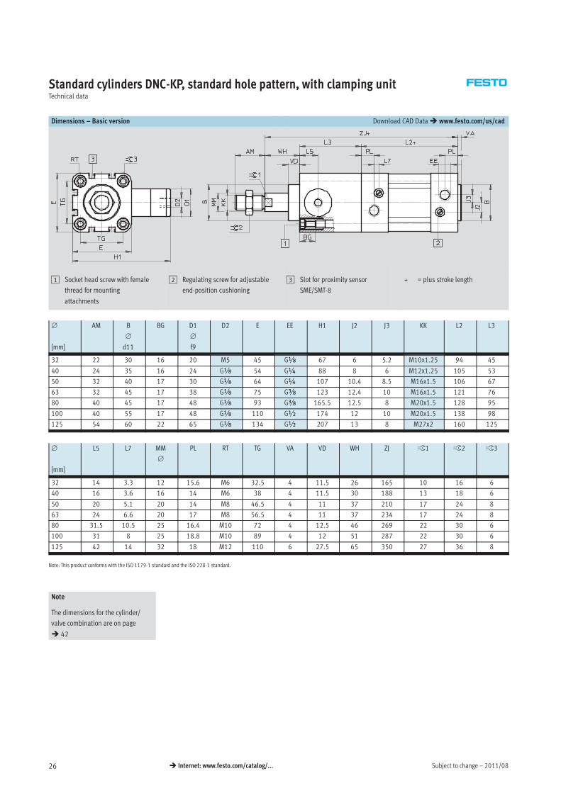
Dimensions – Basic version Download CAD Data� www.festo.com/us/cad
1 Socket head screw with female
thread for mounting
attachments
2 Regulating screw for adjustable
end-position cushioning
3 Slot for proximity sensor
SME/SMT-8
+ = plus stroke length
∅
[mm]
AM B
∅
d11
BG D1
∅
f9
D2 E EE H1 J2 J3 KK L2 L3
32 22 30 16 20 M5 45 Gx 67 6 5.2 M10x1.25 94 45
40 24 35 16 24 Gx 54 G¼ 88 8 6 M12x1.25 105 53
50 32 40 17 30 Gx 64 G¼ 107 10.4 8.5 M16x1.5 106 67
63 32 45 17 38 Gx 75 Gy 123 12.4 10 M16x1.5 121 76
80 40 45 17 48 Gx 93 Gy 165.5 12.5 8 M20x1.5 128 95
100 40 55 17 48 Gx 110 G½ 174 12 10 M20x1.5 138 98
125 54 60 22 65 Gx 134 G½ 207 13 8 M27x2 160 125
∅
[mm]
L5 L7 MM
∅
PL RT TG VA VD WH ZJ ß1 ß2 ß3
32 14 3.3 12 15.6 M6 32.5 4 11.5 26 165 10 16 6
40 16 3.6 16 14 M6 38 4 11.5 30 188 13 18 6
50 20 5.1 20 14 M8 46.5 4 11 37 210 17 24 8
63 24 6.6 20 17 M8 56.5 4 11 37 234 17 24 8
80 31.5 10.5 25 16.4 M10 72 4 12.5 46 269 22 30 6
100 31 8 25 18.8 M10 89 4 12 51 287 22 30 6
125 42 14 32 18 M12 110 6 27.5 65 350 27 36 8
Note: This product conforms with the ISO 1179-1 standard and the ISO 228-1 standard.
Note
The dimensions for the cylinder/
valve combination are on page
� 42
2011/08 – Subject to change 27� Internet: www.festo.com/catalog/...
Standard cylinders DNC-KP, standard hole pattern, with clamping unitTechnical data
Dimensions – Variants Download CAD Data� www.festo.com/us/cad
Q – Square piston rod
Note
Clamping unit and variant Q only in
combination with S2.
S2 – Through piston rod
+ = plus stroke length
++ = plus 2x stroke length
Note
The thread types at both piston rod
ends are identical.
In combination with variant Q,
the left-hand piston rod is round,
the right-hand piston rod square.
The clamping unit is mounted on
the left-hand, round piston rod.
K2 – Extended male piston rod thread K3 – Female piston rod thread
K5 – Special piston rod thread K7 – Piston rod with external hexagon
K8 – Extended piston rod
Note
In combination with variant S2, the
piston rod is extended at one end.
The clamping unit is mounted on the
side of the piston rod that is not
extended. If variant Q is also
required, the extension will only be
added to the square piston rod.
∅ A1 A2 AF AM B1 KF KK T4 WH ZJ ZM ß1
[mm]
max. max. � Basic
thread
Special
thread1)
32 35 500 12 22 10 M6 M10x1.25 M10 2.6 26 165 193 10
40 35 500 12 24 12 M8 M12x1.25 M12 3.3 30 188 220 13
50 70 500 16 32 16 M10 M16x1.5 M16 4.7 37 210 250 17
63 70 500 16 32 16 M10 M16x1.5 M16 4.7 37 234 275 17
80 70 500 20 40 20 M12 M20x1.5 M20 6.1 46 269 317 22
100 70 500 20 40 20 M12 M20x1.5 M20 6.1 51 287 338 22
125 70 500 32 54 – M16 M27x2 M27 8 65 350 416 27
1) The special threads are only available as male threads. The mounting nut on the piston rod thread is included in the scope of delivery
Subject to change – 2011/0828 � Internet: www.festo.com/catalog/...
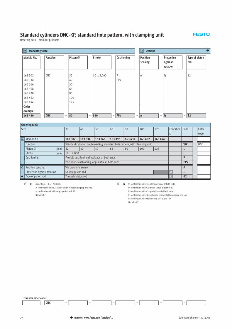
Standard cylinders DNC-KP, standard hole pattern, with clamping unitOrdering data – Modular products
Mandatory data0M Options0O �
Module No. Function Piston∅ Stroke Cushioning Position
sensing
Protection
against
rotation
Type of piston
rod
163 302
163 334
163 366
163 398
163 430
163 462
163 494
DNC 32
40
50
63
80
100
125
10 … 2,000 P
PPV
A Q S2
Order
example
163 430 DNC – 80 – 550 – PPV – A – Q – S2
Ordering table
Size 32 40 50 63 80 100 125 Condition
s
Code Enter
code
0M Module No. 163 302 163 334 163 366 163 398 163 430 163 462 163 494
Function Standard cylinder, double-acting, standard hole pattern, with clamping unit DNC DNC
Piston∅ [mm] 32 40 50 63 80 100 125 -…
Stroke [mm] 10 … 2,000 -…
Cushioning Flexible cushioning rings/pads at both ends -P
Pneumatic cushioning, adjustable at both ends -PPV
0O Position sensing Via proximity sensor -A
Protection against rotation Square piston rod – 1 -Q
� Type of piston rod Through piston rod 2 -S2
1 Q Max. stroke: 10 … 1,500 mm
In combination with S2: square piston rod at bearing cap end only
In combination with KP: only supplied with S2
Not with K7
2 S2 In combination with K2: extended thread at both ends
In combination with K3: female thread at both ends
In combination with K5: special thread at both ends
In combination with K8: piston rod extended at bearing cap end only
In combination with KP: clamping unit at end cap
Not with K7
Transfer order code
DNC – – – – – –
2011/08 – Subject to change 29� Internet: www.festo.com/catalog/...
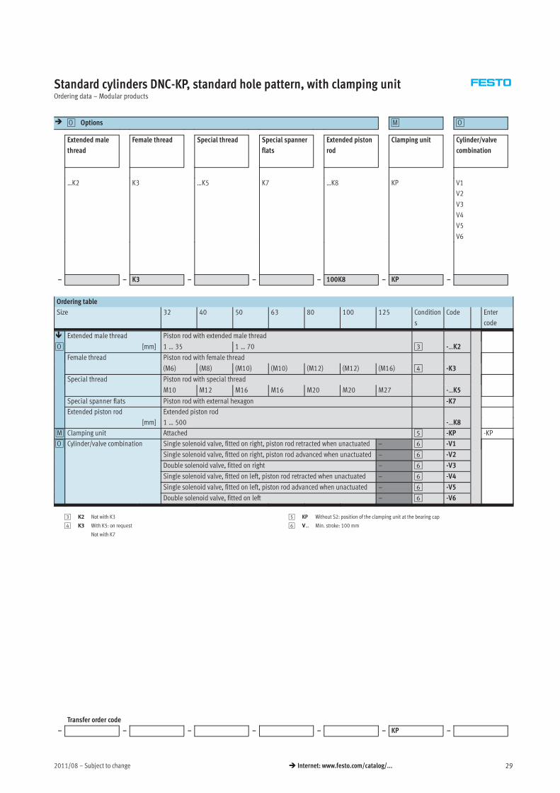
Standard cylinders DNC-KP, standard hole pattern, with clamping unitOrdering data – Modular products
� Options0O 0M 0O
Extended male
thread
Female thread Special thread Special spanner
flats
Extended piston
rod
Clamping unit Cylinder/valve
combination
…K2 K3 …K5 K7 …K8 KP V1
V2
V3
V4
V5
V6
– – K3 – – – 100K8 – KP –
Ordering table
Size 32 40 50 63 80 100 125 Condition
s
Code Enter
code
� Extended male thread Piston rod with extended male thread
0O [mm] 1 … 35 1 … 70 3 -…K2
Female thread Piston rod with female thread
(M6) (M8) (M10) (M10) (M12) (M12) (M16) 4 -K3
Special thread Piston rod with special thread
M10 M12 M16 M16 M20 M20 M27 -…K5
Special spanner flats Piston rod with external hexagon -K7
Extended piston rod Extended piston rod
[mm] 1 … 500 -…K8
0M Clamping unit Attached 5 -KP -KP
0O Cylinder/valve combination Single solenoid valve, fitted on right, piston rod retracted when unactuated – 6 -V1
Single solenoid valve, fitted on right, piston rod advanced when unactuated – 6 -V2
Double solenoid valve, fitted on right – 6 -V3
Single solenoid valve, fitted on left, piston rod retracted when unactuated – 6 -V4
Single solenoid valve, fitted on left, piston rod advanced when unactuated – 6 -V5
Double solenoid valve, fitted on left – 6 -V6
3 K2 Not with K3
4 K3 With K5: on request
Not with K7
5 KP Without S2: position of the clamping unit at the bearing cap
6 V… Min. stroke: 100 mm
Transfer order code
– – – – – – KP –
Subject to change – 2011/0830 � Internet: www.festo.com/catalog/...
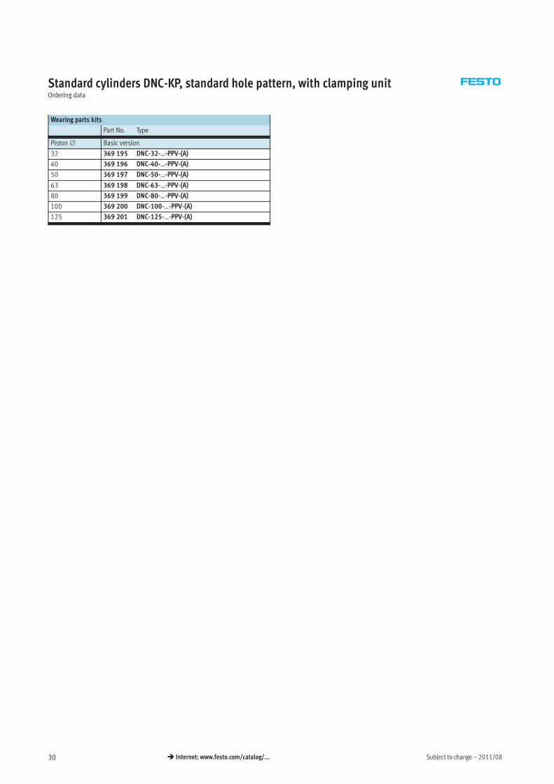
Standard cylinders DNC-KP, standard hole pattern, with clamping unitOrdering data
Wearing parts kits
Part No. Type
Piston∅ Basic version
32 369 195 DNC-32-…-PPV-(A)
40 369 196 DNC-40-…-PPV-(A)
50 369 197 DNC-50-…-PPV-(A)
63 369 198 DNC-63-…-PPV-(A)
80 369 199 DNC-80-…-PPV-(A)
100 369 200 DNC-100-…-PPV-(A)
125 369 201 DNC-125-…-PPV-(A)
2011/08 – Subject to change 31� Internet: www.festo.com/catalog/...
Standard cylinders DNC-EL, standard hole pattern, with end-position lockingTechnical data
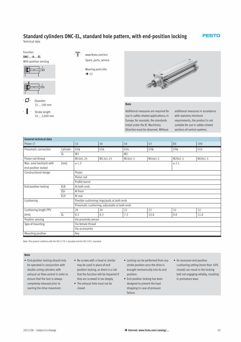
Function
DNC-…-A-…-EL
With position sensing
-N- Diameter
32 … 100 mm
-T- Stroke length
10 … 2,000 mm
-W- www.festo.com/en/
Spare_parts_service
Wearing parts kits
� 22
Note
Additional measures are required for
use in safety-related applications; in
Europe, for example, the standards
listed under the EC Machinery
Directive must be observed. Without
additional measures in accordance
with statutory minimum
requirements, the product is not
suitable for use in safety-related
sections of control systems.
General technical data
Piston∅ 32 40 50 63 80 100
Pneumatic connection Cylinder Gx G¼ G¼ Gy Gy G½
EL M3 M5
Piston rod thread M10x1.25 M12x1.25 M16x1.5 M16x1.5 M20x1.5 M20x1.5
Max. axial backlash with
end position locked
[mm] ≤ 1.3 ≤ 2.1
Constructional design Piston
Piston rod
Profile barrel
End-position locking ELB At both ends
ELV At front
ELH At rear
Cushioning Flexible cushioning rings/pads at both ends
Pneumatic cushioning, adjustable at both ends
Cushioning length PPV
[mm]
20 20 22 22 32 32
EL 8.2 8.3 7.3 10.8 9.8 11.8
Position sensing Via proximity sensor
Type of mounting Via female thread
Via accessories
Mounting position Any
Note: This product conforms with the ISO 1179-1 standard and the ISO 228-1 standard.
Note
• End-position locking should only
be operated in conjunction with
double-acting cylinders with
exhaust air flow control in order to
ensure that the lock is always
completely released prior to
starting the drive movement.
• No screws with a head or similar
may be used in place of end-
position locking, as there is a risk
that the function will be impaired if
they are screwed in too deeply.
• The exhaust hole must not be
closed.
• Locking can be performed from any
stroke position once the drive is
brought mechanically into its end
position.
• End-position locking has been
designed to prevent the load
dropping in case of pressure
failure.
• An excessive end-position
cushioning setting (more than 50%
closed) can result in the locking
bolt not engaging reliably, resulting
in premature wear.
Subject to change – 2011/0832 � Internet: www.festo.com/catalog/...
Standard cylinders DNC-EL, standard hole pattern, with end-position lockingTechnical data
Operating and environmental conditions
Piston∅ 32 40 50 63 80 100
Operating medium Filtered compressed air, lubricated or unlubricated
Operating pressure [bar] 2.5 … 12 1.5 … 12
Ambient temperature1) [°C] –20 … +80
Corrosion resistance class CRC2) 2
Certification Germanischer Lloyd
1) Note operating range of proximity sensors
2) Corrosion resistance class 2 as per Festo standard 940 070
Components subject to moderate corrosion stress. Externally visible parts with primarily decorative surface requirements which are in direct contact with a normal industrial environment or media such as coolants or
lubricating agents.
Impact energy [J]
Piston∅ 32 40 50 63 80 100
Max. impact energy at the end positions 0.1 0.2 0.2 0.5 0.9 1.2
vperm. =
2 x Eperm.
mdead + mload
�
mload =
2 x Eperm.
v2− mdeadMaximum permissible load:
Permissible impact velocity:vperm. Permissible impact velocity
Eperm. Max. impact energy
mIntrinsic Moving load (drive)
mLoad Moving effective load
Note
This data represents the maximum
values that can be achieved. The
maximum permissible impact energy
must be observed.
Forces [N]
Piston∅ 32 40 50 63 80 100
Theoretical force at 6 bar, advancing 483 754 1,178 1,870 3,016 4,712
Theoretical force at 6 bar, retracting 415 633 990 1,682 2,721 4,418
Static holding force 500 2,000 5,000
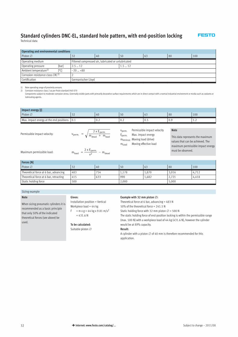
Sizing example
Note
When sizing pneumatic cylinders it is
recommended as a basic principle
that only 50% of the indicated
theoretical forces (see above) be
used.
Given:
Installation position = Vertical
Workpiece load = 44 kg
F = m x g = 44 kg x 9.81 m/s2
= 431.6 N
To be calculated:
Suitable piston∅
Example with 32 mm piston∅:
Theoretical force at 6 bar, advancing = 483 N
50% of the theoretical force = 241.5 N
Static holding force with 32 mm piston∅ = 500 N
The static holding force of end-position locking is within the permissible range
(max. 500 N) with a workpiece load of 44 kg (431.6 N), however the cylinder
would be at 89% capacity.
Result:
A cylinder with a piston∅ of 40 mm is therefore recommended for this
application.
2011/08 – Subject to change 33� Internet: www.festo.com/catalog/...
Standard cylinders DNC-EL, standard hole pattern, with end-position lockingTechnical data
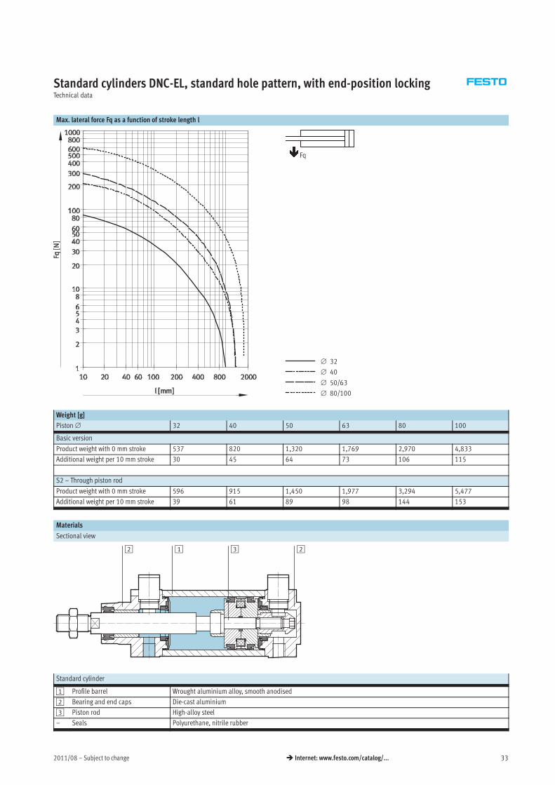
Max. lateral force Fq as a function of stroke length l
∅ 32
∅ 40
∅ 50/63
∅ 80/100
Fq
Weight [g]
Piston∅ 32 40 50 63 80 100
Basic version
Product weight with 0 mm stroke 537 820 1,320 1,769 2,970 4,833
Additional weight per 10 mm stroke 30 45 64 73 106 115
S2 – Through piston rod
Product weight with 0 mm stroke 596 915 1,450 1,977 3,294 5,477
Additional weight per 10 mm stroke 39 61 89 98 144 153
Materials
Sectional view
12 23
Standard cylinder
1 Profile barrel Wrought aluminium alloy, smooth anodised
2 Bearing and end caps Die-cast aluminium
3 Piston rod High-alloy steel
– Seals Polyurethane, nitrile rubber
Subject to change – 2011/0834 � Internet: www.festo.com/catalog/...
Standard cylinders DNC-EL, standard hole pattern, with end-position lockingTechnical data
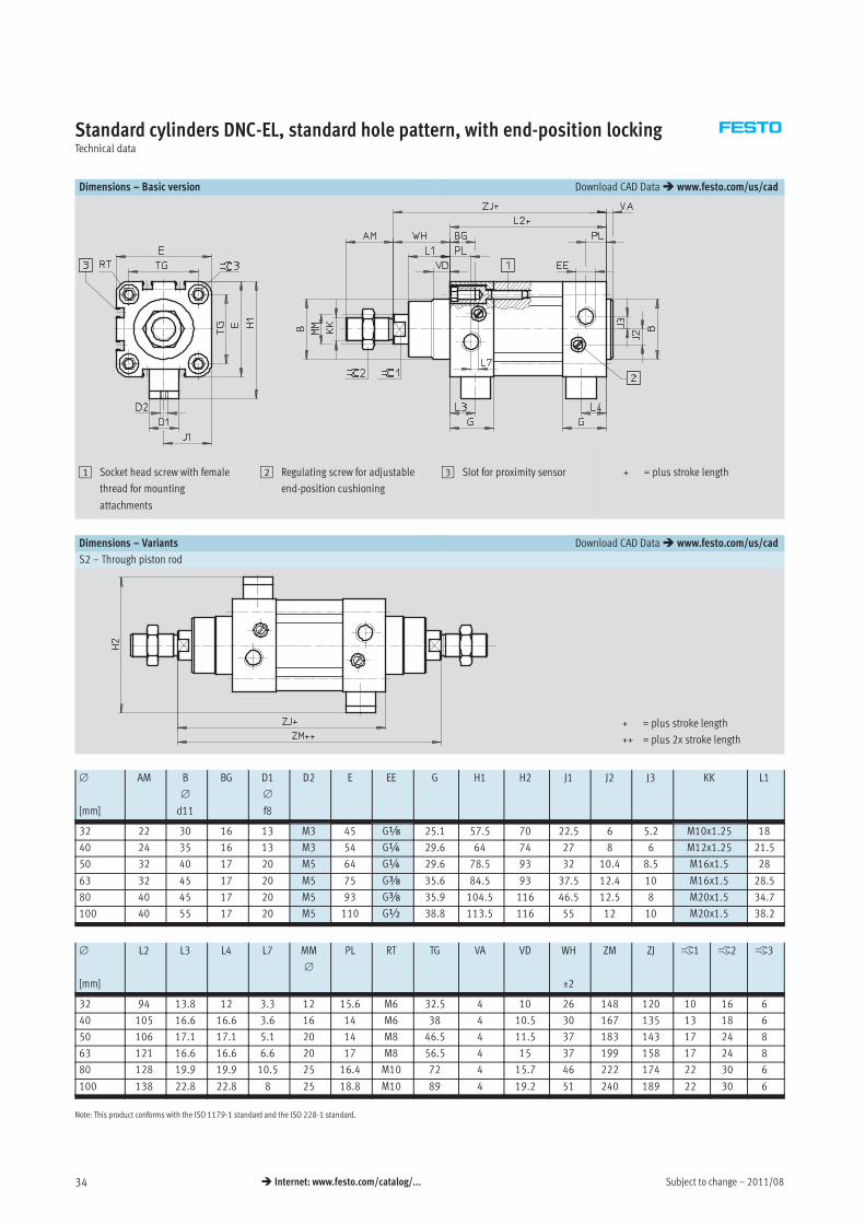
Dimensions – Basic version Download CAD Data� www.festo.com/us/cad
1 Socket head screw with female
thread for mounting
attachments
2 Regulating screw for adjustable
end-position cushioning
3 Slot for proximity sensor + = plus stroke length
Dimensions – Variants Download CAD Data� www.festo.com/us/cad
S2 – Through piston rod
+ = plus stroke length
++ = plus 2x stroke length
∅
[mm]
AM B
∅
d11
BG D1
∅
f8
D2 E EE G H1 H2 J1 J2 J3 KK L1
1
32 22 30 16 13 M3 45 Gx 25.1 57.5 70 22.5 6 5.2 M10x1.25 18
40 24 35 16 13 M3 54 G¼ 29.6 64 74 27 8 6 M12x1.25 21.5
50 32 40 17 20 M5 64 G¼ 29.6 78.5 93 32 10.4 8.5 M16x1.5 28
63 32 45 17 20 M5 75 Gy 35.6 84.5 93 37.5 12.4 10 M16x1.5 28.5
80 40 45 17 20 M5 93 Gy 35.9 104.5 116 46.5 12.5 8 M20x1.5 34.7
100 40 55 17 20 M5 110 G½ 38.8 113.5 116 55 12 10 M20x1.5 38.2
∅
[mm]
L2 L3 L4 L7 MM
∅
PL RT TG VA VD WH
±2
ZM ZJ ß1 ß2 ß3
32 94 13.8 12 3.3 12 15.6 M6 32.5 4 10 26 148 120 10 16 6
40 105 16.6 16.6 3.6 16 14 M6 38 4 10.5 30 167 135 13 18 6
50 106 17.1 17.1 5.1 20 14 M8 46.5 4 11.5 37 183 143 17 24 8
63 121 16.6 16.6 6.6 20 17 M8 56.5 4 15 37 199 158 17 24 8
80 128 19.9 19.9 10.5 25 16.4 M10 72 4 15.7 46 222 174 22 30 6
100 138 22.8 22.8 8 25 18.8 M10 89 4 19.2 51 240 189 22 30 6
Note: This product conforms with the ISO 1179-1 standard and the ISO 228-1 standard.
2011/08 – Subject to change 35� Internet: www.festo.com/catalog/...
Standard cylinders DNC-EL, standard hole pattern, with end-position lockingTechnical data
Dimensions – Variants Download CAD Data� www.festo.com/us/cad
K2 – Extended male piston rod thread
K3 – Female piston rod thread
K5 – Special piston rod thread
K8 – Extended piston rod
Note
In combination with variant S2, the
piston rod is extended at one end.
∅ A1 A2 AF AM KF KK T4 WH ß1
[mm]
max. max. Basic thread Special
thread1)
32 35 500 12 22 M6 M10x1.25 M10 2.6 26 10
40 35 500 12 24 M8 M12x1.25 M12 3.3 30 13
50 70 500 16 32 M10 M16x1.5 M16 4.7 37 17
63 70 500 16 32 M10 M16x1.5 M16 4.7 37 17
80 70 500 20 40 M12 M20x1.5 M20 6.1 46 22
100 70 500 20 40 M12 M20x1.5 M20 6.1 51 22
1) The special threads are only available as male threads. The mounting nut on the piston rod thread is included in the scope of delivery
Subject to change – 2011/0836 � Internet: www.festo.com/catalog/...
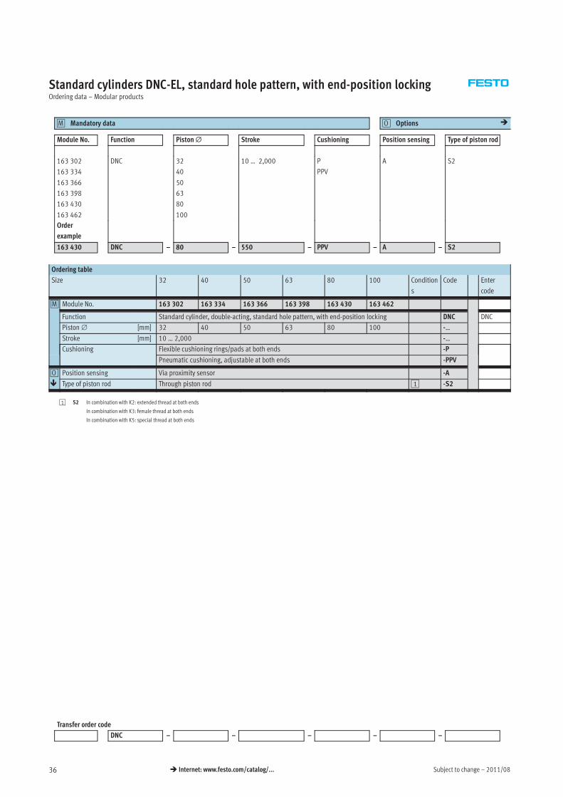
Standard cylinders DNC-EL, standard hole pattern, with end-position lockingOrdering data – Modular products
Mandatory data0M Options0O �
Module No. Function Piston∅ Stroke Cushioning Position sensing Type of piston rod
163 302
163 334
163 366
163 398
163 430
163 462
DNC 32
40
50
63
80
100
10 … 2,000 P
PPV
A S2
Order
example
163 430 DNC – 80 – 550 – PPV – A – S2
Ordering table
Size 32 40 50 63 80 100 Condition
s
Code Enter
code
0M Module No. 163 302 163 334 163 366 163 398 163 430 163 462
Function Standard cylinder, double-acting, standard hole pattern, with end-position locking DNC DNC
Piston∅ [mm] 32 40 50 63 80 100 -…
Stroke [mm] 10 … 2,000 -…
Cushioning Flexible cushioning rings/pads at both ends -P
Pneumatic cushioning, adjustable at both ends -PPV
0O Position sensing Via proximity sensor -A
� Type of piston rod Through piston rod 1 -S2
1 S2 In combination with K2: extended thread at both ends
In combination with K3: female thread at both ends
In combination with K5: special thread at both ends
Transfer order code
DNC – – – – –
2011/08 – Subject to change 37� Internet: www.festo.com/catalog/...
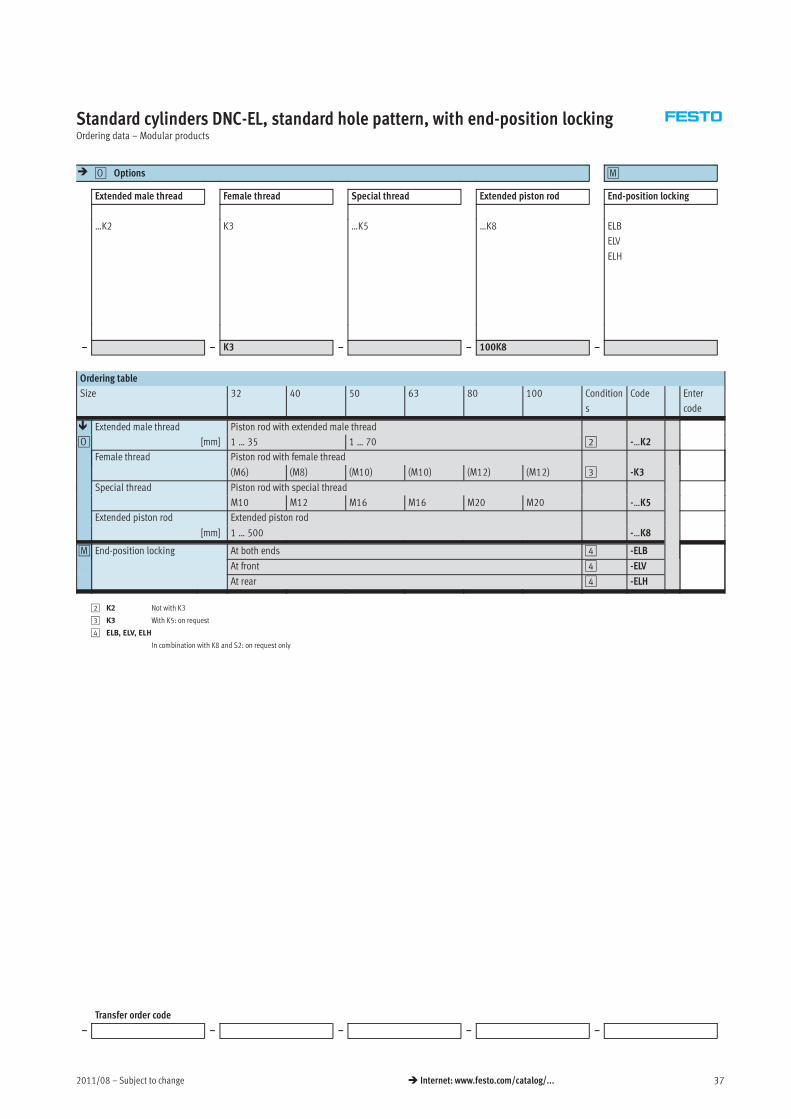
Standard cylinders DNC-EL, standard hole pattern, with end-position lockingOrdering data – Modular products
� Options0O 0M
Extended male thread Female thread Special thread Extended piston rod End-position locking
…K2 K3 …K5 …K8 ELB
ELV
ELH
– – K3 – – 100K8 –
Ordering table
Size 32 40 50 63 80 100 Condition
s
Code Enter
code
� Extended male thread Piston rod with extended male thread
0O [mm] 1 … 35 1 … 70 2 -…K2
Female thread Piston rod with female thread
(M6) (M8) (M10) (M10) (M12) (M12) 3 -K3
Special thread Piston rod with special thread
M10 M12 M16 M16 M20 M20 -…K5
Extended piston rod Extended piston rod
[mm] 1 … 500 -…K8
0M End-position locking At both ends 4 -ELB
At front 4 -ELV
At rear 4 -ELH
2 K2 Not with K3
3 K3 With K5: on request
4 ELB, ELV, ELH
In combination with K8 and S2: on request only
Transfer order code
– – – – –
Subject to change – 2011/0838 � Internet: www.festo.com/catalog/...
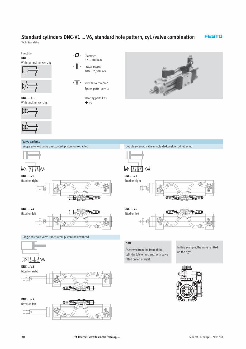
Standard cylinders DNC-V1 … V6, standard hole pattern, cyl./valve combinationTechnical data
Function
DNC-…
Without position sensing
DNC-…-A-…
With position sensing
-N- Diameter
32 … 100 mm
-T- Stroke length
100 … 2,000 mm
-W- www.festo.com/en/
Spare_parts_service
Wearing parts kits
� 30
Valve variants
Single solenoid valve unactuated, piston rod retracted Double solenoid valve unactuated, piston rod retracted
DNC-…-V1
fitted on right
DNC-…-V3
fitted on right
DNC-…-V4
fitted on left
DNC-…-V6
fitted on left
Single solenoid valve unactuated, piston rod advanced
Note
As viewed from the front of the
cylinder (piston rod end) with valve
fitted on left or right.
In this example, the valve is fitted
on the right.
DNC-…-V2
fitted on right
DNC-…-V5
fitted on left
2011/08 – Subject to change 39� Internet: www.festo.com/catalog/...
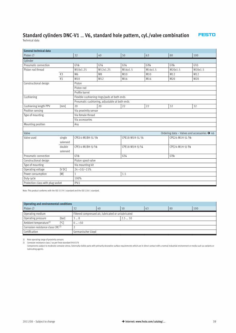
Standard cylinders DNC-V1 … V6, standard hole pattern, cyl./valve combinationTechnical data
General technical data
Piston∅ 32 40 50 63 80 100
Cylinder
Pneumatic connection Gx G¼ G¼ Gy Gy G½
Piston rod thread M10x1.25 M12x1.25 M16x1.5 M16x1.5 M20x1.5 M20x1.5
K3 M6 M8 M10 M10 M12 M12
K5 M10 M12 M16 M16 M20 M20
Constructional design Piston
Piston rod
Profile barrel
Cushioning Flexible cushioning rings/pads at both ends
Pneumatic cushioning, adjustable at both ends
Cushioning length PPV [mm] 20 20 22 22 32 32
Position sensing Via proximity sensor
Type of mounting Via female thread
Via accessories
Mounting position Any
Valve Ordering data – Valves and accessories� 46
Valve used single
solenoid
CPE14-M1BH-5L-x CPE18-M1H-5L-¼ CPE24-M1H-5L-y
double
solenoid
CPE14-M1BH-5J-x CPE18-M1H-5J-¼ CPE24-M1H-5J-y
Pneumatic connection Gx G¼ Gy
Constructional design Piston spool valve
Type of mounting Via mounting kit
Operating voltage [V DC] 24 +10/–15%
Power consumption [W] 1 1.5
Duty cycle 100%
Protection class with plug socket IP65
Note: This product conforms with the ISO 1179-1 standard and the ISO 228-1 standard.
Operating and environmental conditions
Piston∅ 32 40 50 63 80 100
Operating medium Filtered compressed air, lubricated or unlubricated
Operating pressure [bar] 3 … 8 2.5 … 10
Ambient temperature1) [°C] 0 … +50
Corrosion resistance class CRC2) 2
Certification Germanischer Lloyd
1) Note operating range of proximity sensors
2) Corrosion resistance class 2 as per Festo standard 940 070
Components subject to moderate corrosion stress. Externally visible parts with primarily decorative surface requirements which are in direct contact with a normal industrial environment or media such as coolants or
lubricating agents.
Subject to change – 2011/0840 � Internet: www.festo.com/catalog/...
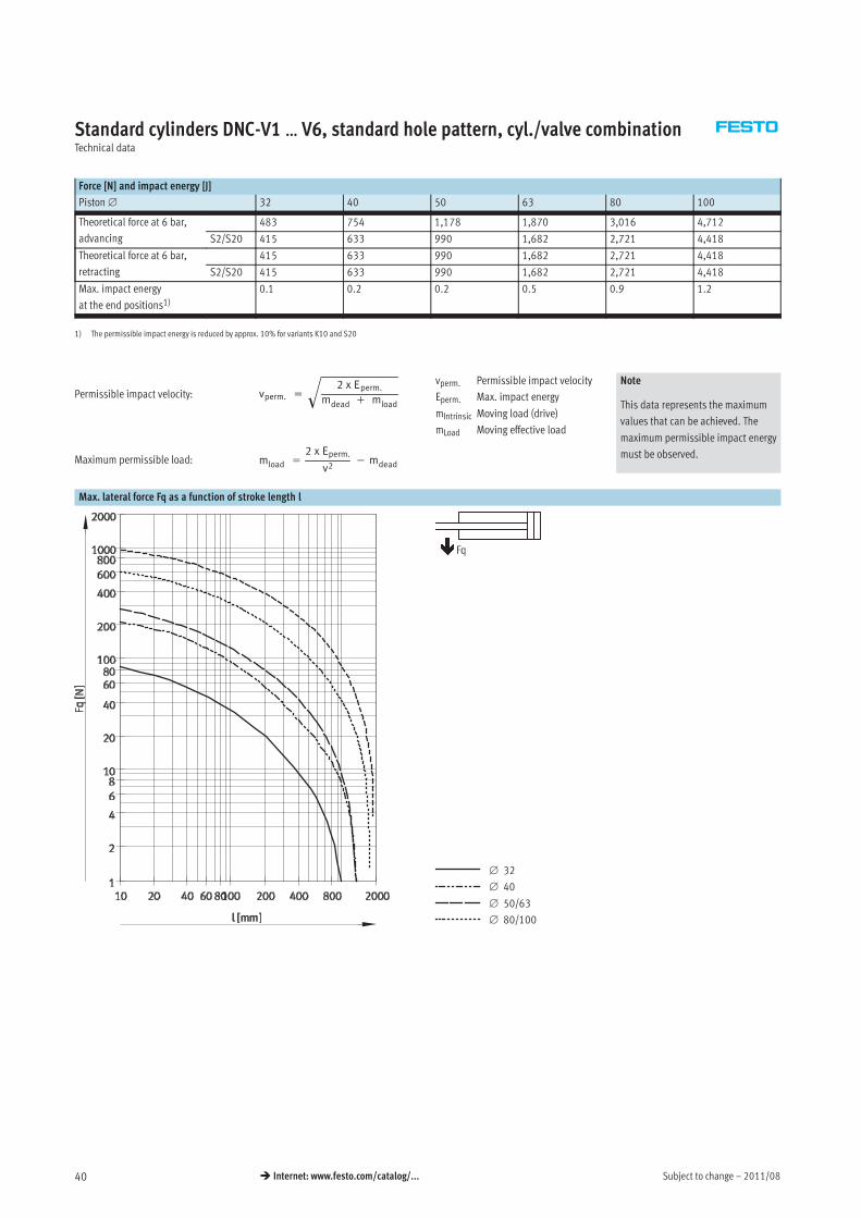
Standard cylinders DNC-V1 … V6, standard hole pattern, cyl./valve combinationTechnical data
Force [N] and impact energy [J]
Piston∅ 32 40 50 63 80 100
Theoretical force at 6 bar,
advancing
483 754 1,178 1,870 3,016 4,712
S2/S20 415 633 990 1,682 2,721 4,418
Theoretical force at 6 bar,
retracting
415 633 990 1,682 2,721 4,418
S2/S20 415 633 990 1,682 2,721 4,418
Max. impact energy
at the end positions1)0.1 0.2 0.2 0.5 0.9 1.2
1) The permissible impact energy is reduced by approx. 10% for variants K10 and S20
vperm. =
2 x Eperm.
mdead + mload
�
mload =
2 x Eperm.
v2− mdeadMaximum permissible load:
Permissible impact velocity:vperm. Permissible impact velocity
Eperm. Max. impact energy
mIntrinsic Moving load (drive)
mLoad Moving effective load
Note
This data represents the maximum
values that can be achieved. The
maximum permissible impact energy
must be observed.
Max. lateral force Fq as a function of stroke length l
∅ 32
∅ 40
∅ 50/63
∅ 80/100
Fq
2011/08 – Subject to change 41� Internet: www.festo.com/catalog/...
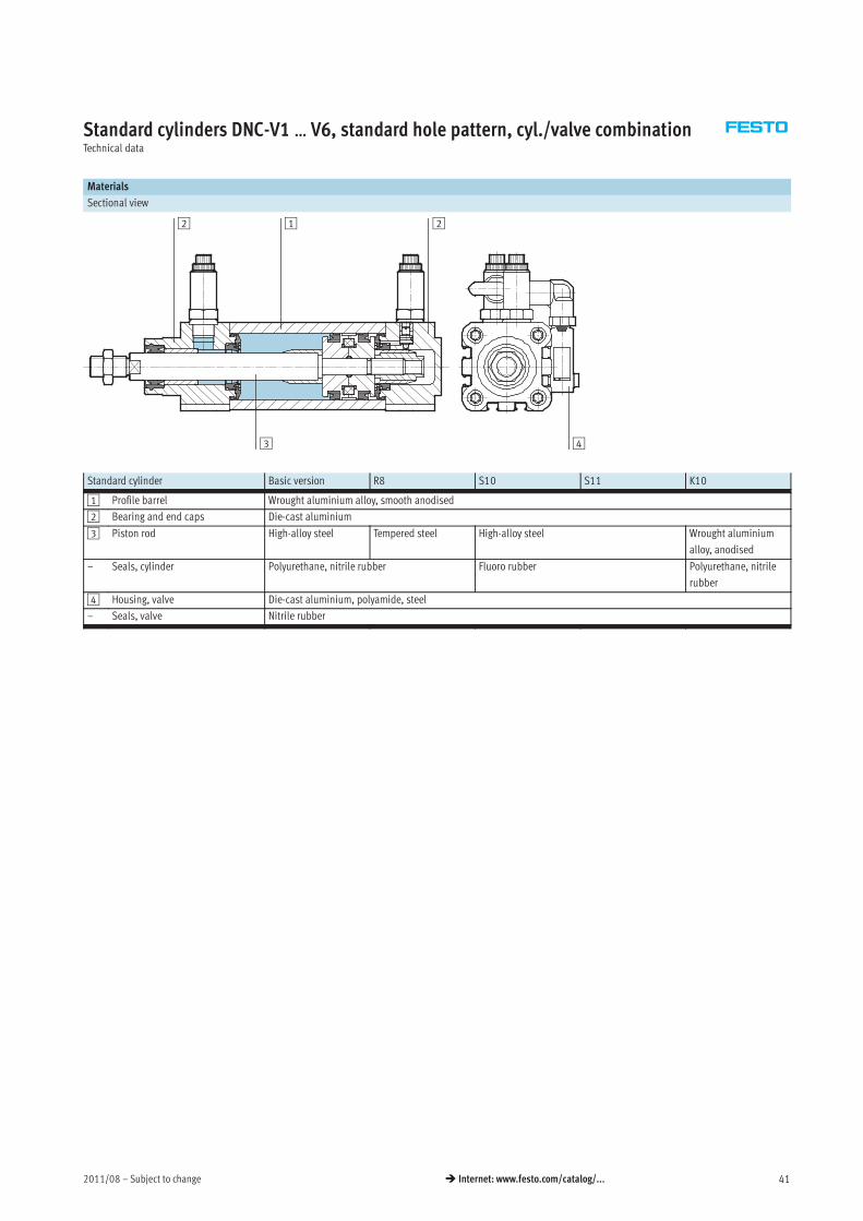
Standard cylinders DNC-V1 … V6, standard hole pattern, cyl./valve combinationTechnical data
Materials
Sectional view
1 22
3 4
Standard cylinder Basic version R8 S10 S11 K10
1 Profile barrel Wrought aluminium alloy, smooth anodised
2 Bearing and end caps Die-cast aluminium
3 Piston rod High-alloy steel Tempered steel High-alloy steel Wrought aluminium
alloy, anodised
– Seals, cylinder Polyurethane, nitrile rubber Fluoro rubber Polyurethane, nitrile
rubber
4 Housing, valve Die-cast aluminium, polyamide, steel
– Seals, valve Nitrile rubber
Subject to change – 2011/0842 � Internet: www.festo.com/catalog/...
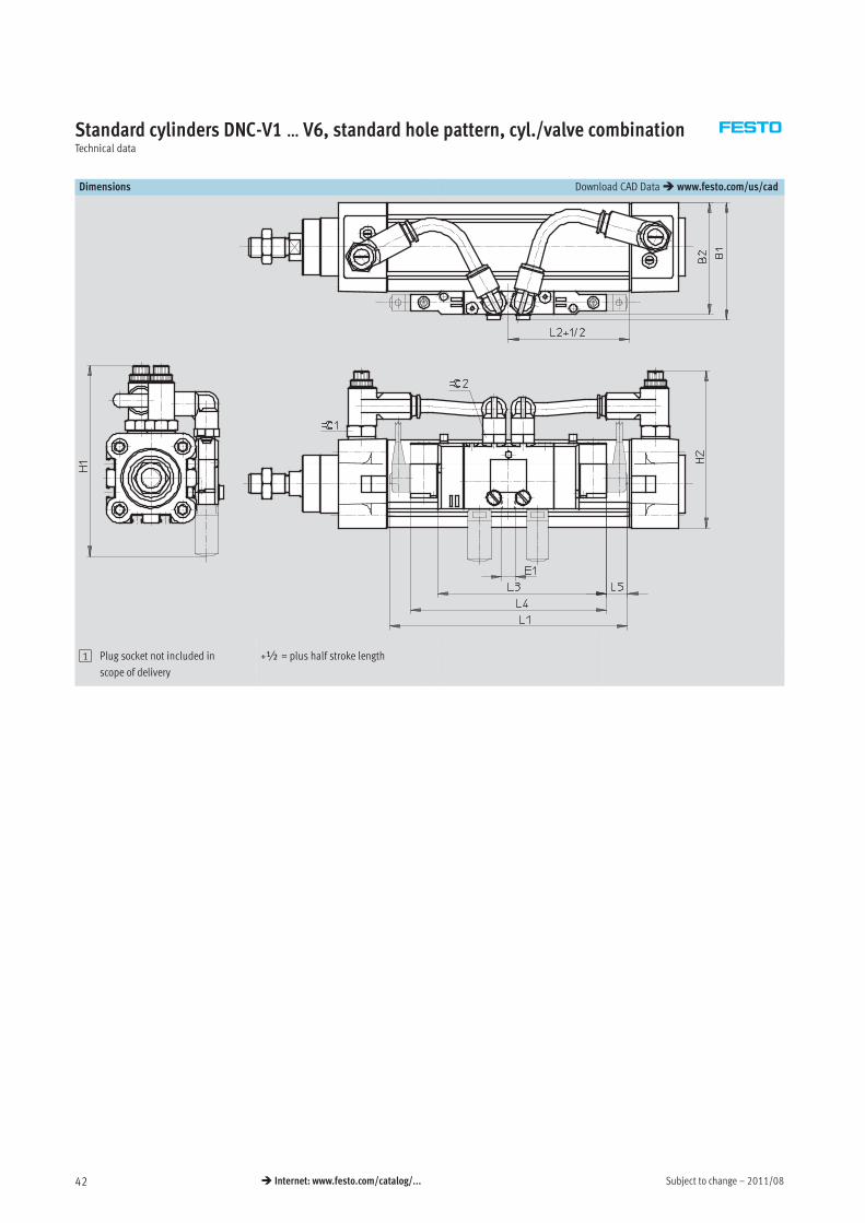
Standard cylinders DNC-V1 … V6, standard hole pattern, cyl./valve combinationTechnical data
Dimensions Download CAD Data� www.festo.com/us/cad
1 Plug socket not included in
scope of delivery
+½ = plus half stroke length
2011/08 – Subject to change 43� Internet: www.festo.com/catalog/...
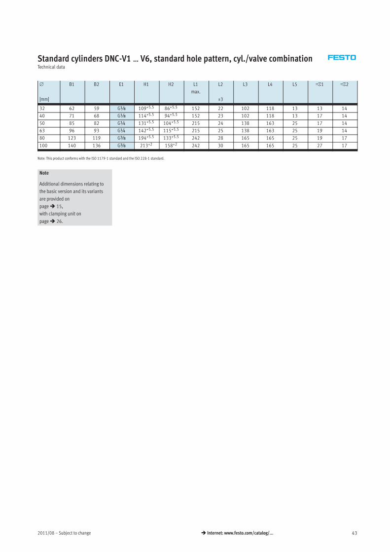
Standard cylinders DNC-V1 … V6, standard hole pattern, cyl./valve combinationTechnical data
∅
[mm]
B1 B2 E1 H1 H2 L1
max.
L2
±3
L3 L4 L5 ß1 ß2
32 62 59 Gx 109+5.5 86+5.5 152 22 102 118 13 13 14
40 71 68 Gx 114+5.5 94+5.5 152 23 102 118 13 17 14
50 85 82 G¼ 131+5.5 104+5.5 215 24 138 163 25 17 14
63 96 93 G¼ 142+5.5 115+5.5 215 25 138 163 25 19 14
80 123 119 Gy 194+5.5 133+5.5 242 28 165 165 25 19 17
100 140 136 Gy 213+2 158+2 242 30 165 165 25 27 17
Note: This product conforms with the ISO 1179-1 standard and the ISO 228-1 standard.
Note
Additional dimensions relating to
the basic version and its variants
are provided on
page� 15,
with clamping unit on
page� 26.
Subject to change – 2011/0844 � Internet: www.festo.com/catalog/...
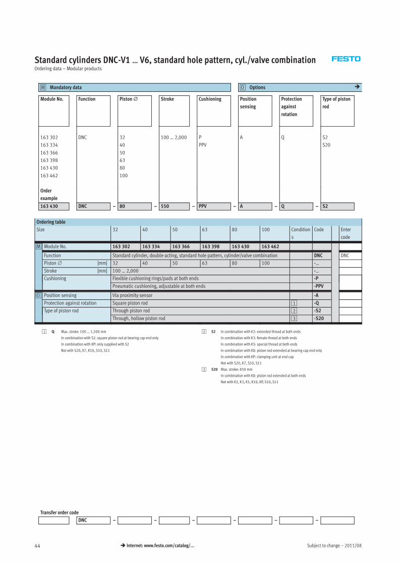
Standard cylinders DNC-V1 … V6, standard hole pattern, cyl./valve combinationOrdering data – Modular products
Mandatory data0M Options0O �
Module No. Function Piston∅ Stroke Cushioning Position
sensing
Protection
against
rotation
Type of piston
rod
163 302
163 334
163 366
163 398
163 430
163 462
DNC 32
40
50
63
80
100
100 … 2,000 P
PPV
A Q S2
S20
Order
example
163 430 DNC – 80 – 550 – PPV – A – Q – S2
Ordering table
Size 32 40 50 63 80 100 Condition
s
Code Enter
code
0M Module No. 163 302 163 334 163 366 163 398 163 430 163 462
Function Standard cylinder, double-acting, standard hole pattern, cylinder/valve combination DNC DNC
Piston∅ [mm] 32 40 50 63 80 100 -…
Stroke [mm] 100 … 2,000 -…
Cushioning Flexible cushioning rings/pads at both ends -P
Pneumatic cushioning, adjustable at both ends -PPV
0O Position sensing Via proximity sensor -A
Protection against rotation Square piston rod 1 -Q
Type of piston rod Through piston rod 2 -S2
Through, hollow piston rod 3 -S20
1 Q Max. stroke: 100 … 1,500 mm
In combination with S2: square piston rod at bearing cap end only
In combination with KP: only supplied with S2
Not with S20, K7, K10, S10, S11
2 S2 In combination with K2: extended thread at both ends
In combination with K3: female thread at both ends
In combination with K5: special thread at both ends
In combination with K8: piston rod extended at bearing cap end only
In combination with KP: clamping unit at end cap
Not with S20, K7, S10, S11
3 S20 Max. stroke: 850 mm
In combination with K8: piston rod extended at both ends
Not with K2, K3, K5, K10, KP, S10, S11
Transfer order code
DNC – – – – – –
2011/08 – Subject to change 45� Internet: www.festo.com/catalog/...
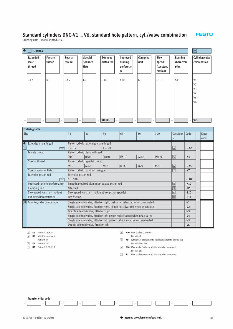
Standard cylinders DNC-V1 … V6, standard hole pattern, cyl./valve combinationOrdering data – Modular products
� Options0O 0M
Extended
male
thread
Female
thread
Special
thread
Special
spanner
flats
Extended
piston rod
Improved
running
performan
ce
Clamping
unit
Slow
speed
(constant
motion)
Running
characteri
stics
Cylinder/valve
combination
…K2 K3 …K5 K7 …K8 K10 KP S10 S11 V1
V2
V3
V4
V5
V6
– – – – – 100K8 – – – – – V2
Ordering table
Size 32 40 50 63 80 100 Condition
s
Code Enter
code
� Extended male thread Piston rod with extended male thread
0O [mm] 1 … 35 1 … 70 4 -…K2
Female thread Piston rod with female thread
(M6) (M8) (M10) (M10) (M12) (M12) 5 -K3
Special thread Piston rod with special thread
M10 M12 M16 M16 M20 M20 6 -…K5
Special spanner flats Piston rod with external hexagon 7 -K7
Extended piston rod Extended piston rod
[mm] 1 … 500 -…K8
Improved running performance Smooth anodised aluminium coated piston rod 8 -K10
Clamping unit Attached 9 -KP
Slow speed (constant motion) Slow speed (constant motion at low piston speeds) aJ -S10
Running characteristics Low friction aA -S11
0M Cylinder/valve combination Single solenoid valve, fitted on right, piston rod retracted when unactuated -V1
Single solenoid valve, fitted on right, piston rod advanced when unactuated -V2
Double solenoid valve, fitted on right -V3
Single solenoid valve, fitted on left, piston rod retracted when unactuated -V4
Single solenoid valve, fitted on left, piston rod advanced when unactuated -V5
Double solenoid valve, fitted on left -V6
4 K2 Not with K3, K10
5 K3 With K5: on request
Not with K7
6 K5 Not with K10
7 K7 Not with Q, S2, K10
8 K10 Max. stroke: 1,000 mm
Not with KP
9 KP Without S2: position of the clamping unit at the bearing cap
Not with S10, S11
aJ S10 Max. stroke: 500 mm; additional strokes on request
Not with S11
aA S11 Max. stroke: 500 mm; additional strokes on request
Transfer order code
– – – – – – – – – –
Subject to change – 2011/0846 � Internet: www.festo.com/catalog/...
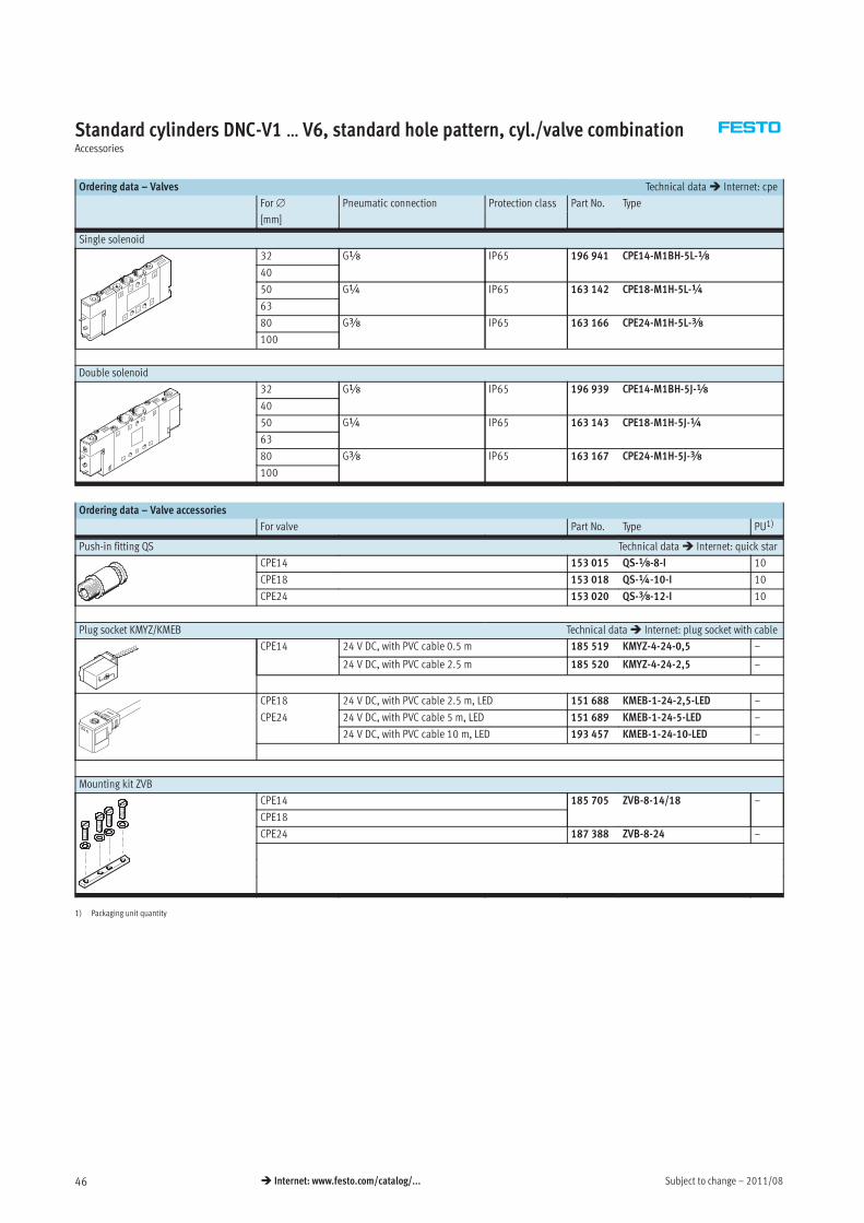
Standard cylinders DNC-V1 … V6, standard hole pattern, cyl./valve combinationAccessories
Ordering data – Valves Technical data� Internet: cpe
For∅ Pneumatic connection Protection class Part No. Type
[mm]
Single solenoid
32 Gx IP65 196 941 CPE14-M1BH-5L-x
40
50 G¼ IP65 163 142 CPE18-M1H-5L-¼
63
80 Gy IP65 163 166 CPE24-M1H-5L-y
100
Double solenoid
32 Gx IP65 196 939 CPE14-M1BH-5J-x
40
50 G¼ IP65 163 143 CPE18-M1H-5J-¼
63
80 Gy IP65 163 167 CPE24-M1H-5J-y
100
Ordering data – Valve accessories
For valve Part No. Type PU1)
Push-in fitting QS Technical data� Internet: quick star
CPE14 153 015 QS-x-8-I 10
CPE18 153 018 QS-¼-10-I 10
CPE24 153 020 QS-y-12-I 10
Plug socket KMYZ/KMEB Technical data� Internet: plug socket with cable
CPE14 24 V DC, with PVC cable 0.5 m 185 519 KMYZ-4-24-0,5 –
24 V DC, with PVC cable 2.5 m 185 520 KMYZ-4-24-2,5 –
CPE18 24 V DC, with PVC cable 2.5 m, LED 151 688 KMEB-1-24-2,5-LED –
CPE24 24 V DC, with PVC cable 5 m, LED 151 689 KMEB-1-24-5-LED –
24 V DC, with PVC cable 10 m, LED 193 457 KMEB-1-24-10-LED –
Mounting kit ZVB
CPE14 185 705 ZVB-8-14/18 –
CPE18
CPE24 187 388 ZVB-8-24 –
1) Packaging unit quantity
2011/08 – Subject to change 47� Internet: www.festo.com/catalog/...
Standard cylinders DNC, ISO 15552Accessories
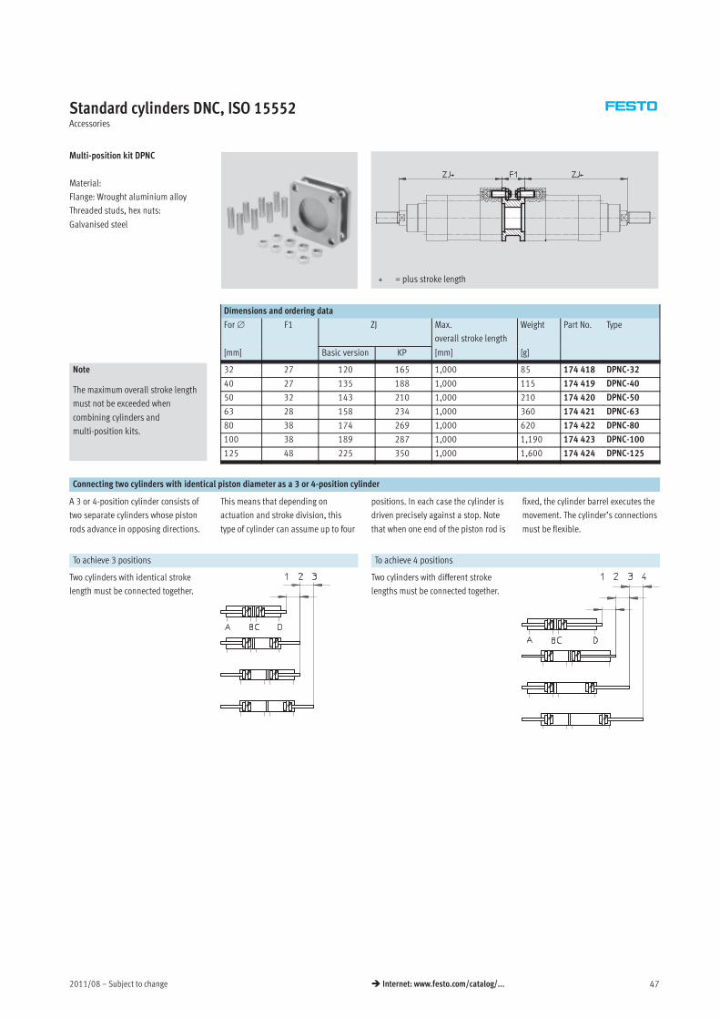
Multi-position kit DPNC
Material:
Flange: Wrought aluminium alloy
Threaded studs, hex nuts:
Galvanised steel
+ = plus stroke length
Dimensions and ordering data
For∅ F1 ZJ Max.
overall stroke length
Weight Part No. Type
[mm] Basic version KP [mm] [g]
Note
The maximum overall stroke length
must not be exceeded when
combining cylinders and
multi-position kits.
32 27 120 165 1,000 85 174 418 DPNC-32
40 27 135 188 1,000 115 174 419 DPNC-40
50 32 143 210 1,000 210 174 420 DPNC-50
63 28 158 234 1,000 360 174 421 DPNC-63
80 38 174 269 1,000 620 174 422 DPNC-80
100 38 189 287 1,000 1,190 174 423 DPNC-100
125 48 225 350 1,000 1,600 174 424 DPNC-125
Connecting two cylinders with identical piston diameter as a 3 or 4-position cylinder
A 3 or 4-position cylinder consists of
two separate cylinders whose piston
rods advance in opposing directions.
This means that depending on
actuation and stroke division, this
type of cylinder can assume up to four
positions. In each case the cylinder is
driven precisely against a stop. Note
that when one end of the piston rod is
fixed, the cylinder barrel executes the
movement. The cylinder’s connections
must be flexible.
To achieve 3 positions To achieve 4 positions
Two cylinders with identical stroke
length must be connected together.
Two cylinders with different stroke
lengths must be connected together.
Subject to change – 2011/0848 � Internet: www.festo.com/catalog/...
Standard cylinders DNC, ISO 15552Accessories
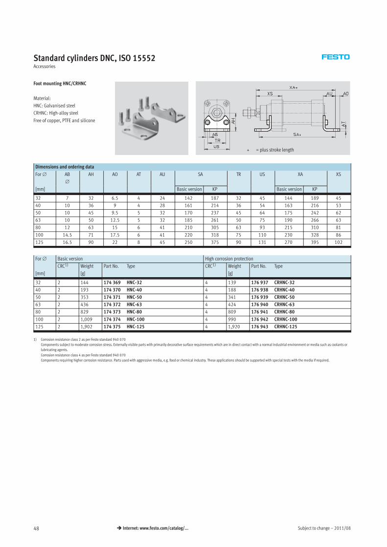
Foot mounting HNC/CRHNC
Material:
HNC: Galvanised steel
CRHNC: High-alloy steel
Free of copper, PTFE and silicone
+ = plus stroke length
Dimensions and ordering data
For∅ AB
∅
AH AO AT AU SA TR US XA XS
[mm] Basic version KP Basic version KP
32 7 32 6.5 4 24 142 187 32 45 144 189 45
40 10 36 9 4 28 161 214 36 54 163 216 53
50 10 45 9.5 5 32 170 237 45 64 175 242 62
63 10 50 12.5 5 32 185 261 50 75 190 266 63
80 12 63 15 6 41 210 305 63 93 215 310 81
100 14.5 71 17.5 6 41 220 318 75 110 230 328 86
125 16.5 90 22 8 45 250 375 90 131 270 395 102
For∅ Basic version High corrosion protection
[mm]
CRC1) Weight
[g]
Part No. Type CRC1) Weight
[g]
Part No. Type
32 2 144 174 369 HNC-32 4 139 176 937 CRHNC-32
40 2 193 174 370 HNC-40 4 188 176 938 CRHNC-40
50 2 353 174 371 HNC-50 4 341 176 939 CRHNC-50
63 2 436 174 372 HNC-63 4 424 176 940 CRHNC-63
80 2 829 174 373 HNC-80 4 809 176 941 CRHNC-80
100 2 1,009 174 374 HNC-100 4 990 176 942 CRHNC-100
125 2 1,902 174 375 HNC-125 4 1,920 176 943 CRHNC-125
1) Corrosion resistance class 2 as per Festo standard 940 070
Components subject to moderate corrosion stress. Externally visible parts with primarily decorative surface requirements which are in direct contact with a normal industrial environment or media such as coolants or
lubricating agents.
Corrosion resistance class 4 as per Festo standard 940 070
Components requiring higher corrosion resistance. Parts used with aggressive media, e.g. food or chemical industry. These applications should be supported with special tests with the media if required.
2011/08 – Subject to change 49� Internet: www.festo.com/catalog/...
Standard cylinders DNC, ISO 15552Accessories
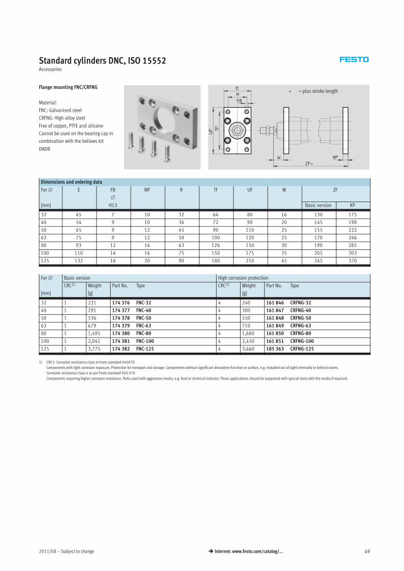
Flange mounting FNC/CRFNG
Material:
FNC: Galvanised steel
CRFNG: High-alloy steel
Free of copper, PTFE and silicone
Cannot be used on the bearing cap in
combination with the bellows kit
DADB
+ = plus stroke length
Dimensions and ordering data
For∅ E FB
∅
MF R TF UF W ZF
[mm] H13 Basic version KP
32 45 7 10 32 64 80 16 130 175
40 54 9 10 36 72 90 20 145 198
50 65 9 12 45 90 110 25 155 222
63 75 9 12 50 100 120 25 170 246
80 93 12 16 63 126 150 30 190 285
100 110 14 16 75 150 175 35 205 303
125 132 16 20 90 180 210 45 245 370
For∅ Basic version High corrosion protection
[mm]
CRC1) Weight
[g]
Part No. Type CRC1) Weight
[g]
Part No. Type
32 1 221 174 376 FNC-32 4 240 161 846 CRFNG-32
40 1 291 174 377 FNC-40 4 300 161 847 CRFNG-40
50 1 536 174 378 FNC-50 4 550 161 848 CRFNG-50
63 1 679 174 379 FNC-63 4 710 161 849 CRFNG-63
80 1 1,495 174 380 FNC-80 4 1,680 161 850 CRFNG-80
100 1 2,041 174 381 FNC-100 4 2,450 161 851 CRFNG-100
125 1 3,775 174 382 FNC-125 4 3,660 185 363 CRFNG-125
1) CRC1: Corrosion resistance class to Festo standard 940070
Components with light corrosion exposure. Protection for transport and storage. Components without significant decorative function or surface, e.g. installed out of sight internally or behind covers.
Corrosion resistance class 4 as per Festo standard 940 070
Components requiring higher corrosion resistance. Parts used with aggressive media, e.g. food or chemical industry. These applications should be supported with special tests with the media if required.
Subject to change – 2011/0850 � Internet: www.festo.com/catalog/...
Standard cylinders DNC, ISO 15552Accessories
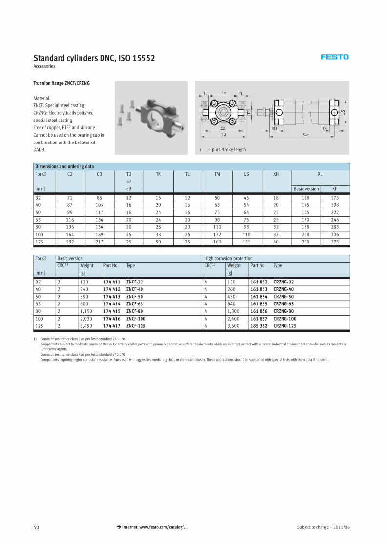
Trunnion flange ZNCF/CRZNG
Material:
ZNCF: Special steel casting
CRZNG: Electrolytically polished
special steel casting
Free of copper, PTFE and silicone
Cannot be used on the bearing cap in
combination with the bellows kit
DADB + = plus stroke length
Dimensions and ordering data
For∅ C2 C3 TD
∅
TK TL TM US XH XL
[mm] e9 Basic version KP
32 71 86 12 16 12 50 45 18 128 173
40 87 105 16 20 16 63 54 20 145 198
50 99 117 16 24 16 75 64 25 155 222
63 116 136 20 24 20 90 75 25 170 246
80 136 156 20 28 20 110 93 32 188 283
100 164 189 25 38 25 132 110 32 208 306
125 192 217 25 50 25 160 131 40 250 375
For∅ Basic version High corrosion protection
[mm]
CRC1) Weight
[g]
Part No. Type CRC1) Weight
[g]
Part No. Type
32 2 130 174 411 ZNCF-32 4 150 161 852 CRZNG-32
40 2 240 174 412 ZNCF-40 4 260 161 853 CRZNG-40
50 2 390 174 413 ZNCF-50 4 430 161 854 CRZNG-50
63 2 600 174 414 ZNCF-63 4 640 161 855 CRZNG-63
80 2 1,150 174 415 ZNCF-80 4 1,300 161 856 CRZNG-80
100 2 2,030 174 416 ZNCF-100 4 2,400 161 857 CRZNG-100
125 2 3,490 174 417 ZNCF-125 4 3,600 185 362 CRZNG-125
1) Corrosion resistance class 2 as per Festo standard 940 070
Components subject to moderate corrosion stress. Externally visible parts with primarily decorative surface requirements which are in direct contact with a normal industrial environment or media such as coolants or
lubricating agents.
Corrosion resistance class 4 as per Festo standard 940 070
Components requiring higher corrosion resistance. Parts used with aggressive media, e.g. food or chemical industry. These applications should be supported with special tests with the media if required.
2011/08 – Subject to change 51� Internet: www.festo.com/catalog/...
Standard cylinders DNC, ISO 15552Accessories
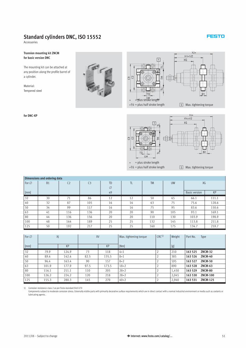
Trunnion mounting kit ZNCM
for basic version DNC
The mounting kit can be attached at
any position along the profile barrel of
a cylinder.
Material:
Tempered steel
+ = plus stroke length
+½ = plus half stroke length 1 Max. tightening torque
for DNC-KP
+ = plus stroke length
+½ = plus half stroke length 1 Max. tightening torque
Dimensions and ordering data
For∅ B1 C2 C3 TD
∅
TL TM UW XG
[mm] e9 Basic version KP
32 30 71 86 12 12 50 65 66.1 111.1
40 32 87 105 16 16 63 75 75.6 128.6
50 34 99 117 16 16 75 95 83.6 150.6
63 41 116 136 20 20 90 105 93.1 169.1
80 44 136 156 20 20 110 130 103.9 198.9
100 48 164 189 25 25 132 145 113.8 211.8
125 50 192 217 25 25 160 175 134.7 259.7
For∅ XJ XV Max. tightening torque CRC1) Weight Part No. Type
[mm] KP KP [Nm] [g]
32 79.9 124.9 73 118 4+1 2 210 163 525 ZNCM-32
40 89.4 142.4 82.5 135.5 8+1 2 385 163 526 ZNCM-40
50 96.4 163.4 90 157 8+2 2 595 163 527 ZNCM-50
63 101.9 177.9 97.5 173.5 18+2 2 890 163 528 ZNCM-63
80 116.1 211.1 110 205 28+2 2 1,450 163 529 ZNCM-80
100 126.2 224.2 120 218 28+2 2 2,045 163 530 ZNCM-100
125 155.3 280.3 145 270 40+2 2 2,940 163 531 ZNCM-125
1) Corrosion resistance class 2 as per Festo standard 940 070
Components subject to moderate corrosion stress. Externally visible parts with primarily decorative surface requirements which are in direct contact with a normal industrial environment or media such as coolants or
lubricating agents.
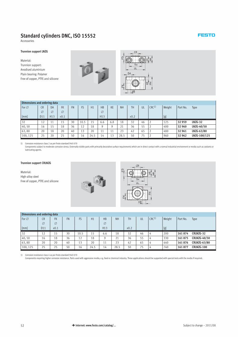
Subject to change – 2011/0852 � Internet: www.festo.com/catalog/...
Standard cylinders DNC, ISO 15552Accessories
Trunnion support LNZG
Material:
Trunnion support:
Anodised aluminium
Plain bearing: Polymer
Free of copper, PTFE and silicone
Dimensions and ordering data
For∅ CR
∅
DA
∅
FK
∅
FN FS H1 HB
∅
KE NH TH UL CRC1) Weight Part No. Type
[mm] D11 H13 ±0.1 H13 ±0.2 [g]
32 12 11 15 30 10.5 15 6.6 6.8 18 32 46 2 125 32 959 LNZG-32
40, 50 16 15 18 36 12 18 9 9 21 36 55 2 400 32 960 LNZG-40/50
63, 80 20 18 20 40 13 20 11 11 23 42 65 2 480 32 961 LNZG-63/80
100, 125 25 20 25 50 16 24.5 14 13 28.5 50 75 2 960 32 962 LNZG-100/125
1) Corrosion resistance class 2 as per Festo standard 940 070
Components subject to moderate corrosion stress. Externally visible parts with primarily decorative surface requirements which are in direct contact with a normal industrial environment or media such as coolants or
lubricating agents.
Trunnion support CRLNZG
Material:
High-alloy steel
Free of copper, PTFE and silicone
Dimensions and ordering data
For∅ CR
∅
FK
∅
FN FS H1 HB
∅
NH TH UL CRC1) Weight Part No. Type
[mm] D11 ±0.1 H13 ±0.2 [g]
32 12 15 30 10.5 15 6.6 18 32 46 4 200 161 874 CRLNZG-32
40, 50 16 18 36 12 18 9 21 36 55 4 330 161 875 CRLNZG-40/50
63, 80 20 20 40 13 20 11 23 42 65 4 440 161 876 CRLNZG-63/80
100, 125 25 25 50 16 24.5 14 28.5 50 75 4 740 161 877 CRLNZG-100
1) Corrosion resistance class 4 as per Festo standard 940 070
Components requiring higher corrosion resistance. Parts used with aggressive media, e.g. food or chemical industry. These applications should be supported with special tests with the media if required.
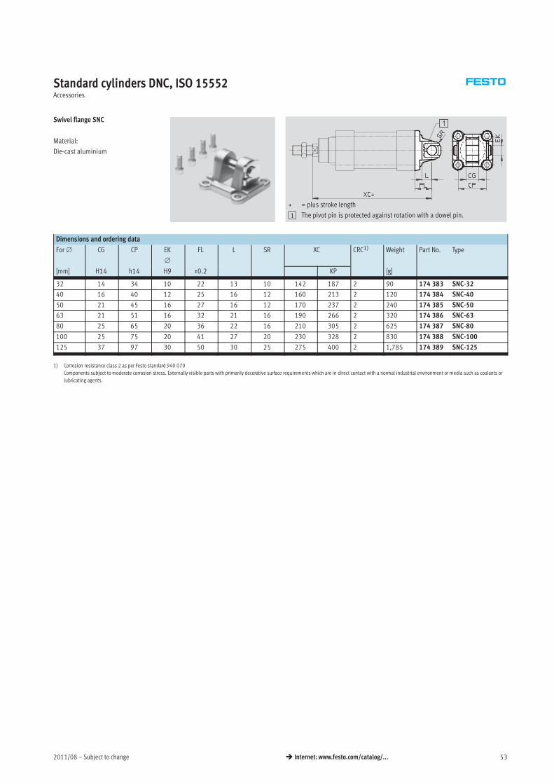
2011/08 – Subject to change 53� Internet: www.festo.com/catalog/...
Standard cylinders DNC, ISO 15552Accessories
Swivel flange SNC
Material:
Die-cast aluminium
+ = plus stroke length
1 The pivot pin is protected against rotation with a dowel pin.
Dimensions and ordering data
For∅ CG CP EK
∅
FL L SR XC CRC1) Weight Part No. Type
[mm] H14 h14 H9 ±0.2 KP [g]
32 14 34 10 22 13 10 142 187 2 90 174 383 SNC-32
40 16 40 12 25 16 12 160 213 2 120 174 384 SNC-40
50 21 45 16 27 16 12 170 237 2 240 174 385 SNC-50
63 21 51 16 32 21 16 190 266 2 320 174 386 SNC-63
80 25 65 20 36 22 16 210 305 2 625 174 387 SNC-80
100 25 75 20 41 27 20 230 328 2 830 174 388 SNC-100
125 37 97 30 50 30 25 275 400 2 1,785 174 389 SNC-125
1) Corrosion resistance class 2 as per Festo standard 940 070
Components subject to moderate corrosion stress. Externally visible parts with primarily decorative surface requirements which are in direct contact with a normal industrial environment or media such as coolants or
lubricating agents.

Subject to change – 2011/0854 � Internet: www.festo.com/catalog/...
Standard cylinders DNC, ISO 15552Accessories
Swivel flange
SNCB/SNCB-…-R3
Material:
SNCB: Die-cast aluminium
SNCB-…-R3: Die-cast aluminium with
protective coating, high corrosion
protection
Free of copper, PTFE and silicone
+ = plus stroke length
Dimensions and ordering data
For∅ CB EK
∅
FL L MR UB XC
[mm] H14 e8 ±0.2 h14 KP
32 26 10 22 13 8.5 45 142 187
40 28 12 25 16 12 52 160 213
50 32 12 27 16 12 60 170 237
63 40 16 32 21 16 70 190 266
80 50 16 36 22 16 90 210 305
100 60 20 41 27 20 110 230 328
125 70 25 50 30 25 130 275 400
For∅ Basic version Variant R3 – High corrosion protection
[mm]
CRC1) Weight
[g]
Part No. Type CRC1) Weight
[g]
Part No. Type
32 2 100 174 390 SNCB-32 3 100 176 944 SNCB-32-R3
40 2 150 174 391 SNCB-40 3 150 176 945 SNCB-40-R3
50 2 225 174 392 SNCB-50 3 225 176 946 SNCB-50-R3
63 2 365 174 393 SNCB-63 3 365 176 947 SNCB-63-R3
80 2 610 174 394 SNCB-80 3 610 176 948 SNCB-80-R3
100 2 925 174 395 SNCB-100 3 925 176 949 SNCB-100-R3
125 2 1,785 174 396 SNCB-125 3 1,785 176 950 SNCB-125-R3
1) Corrosion resistance class 2 as per Festo standard 940 070
Components subject to moderate corrosion stress. Externally visible parts with primarily decorative surface requirements which are in direct contact with a normal industrial environment or media such as coolants or
lubricating agents.
Corrosion resistance class 3 as per Festo standard 940 070
Components requiring higher corrosion resistance. External visible parts in direct contact with industrial atmospheres or media such as solvents and cleaning agents, with a predominantly functional requirement for
the surface.
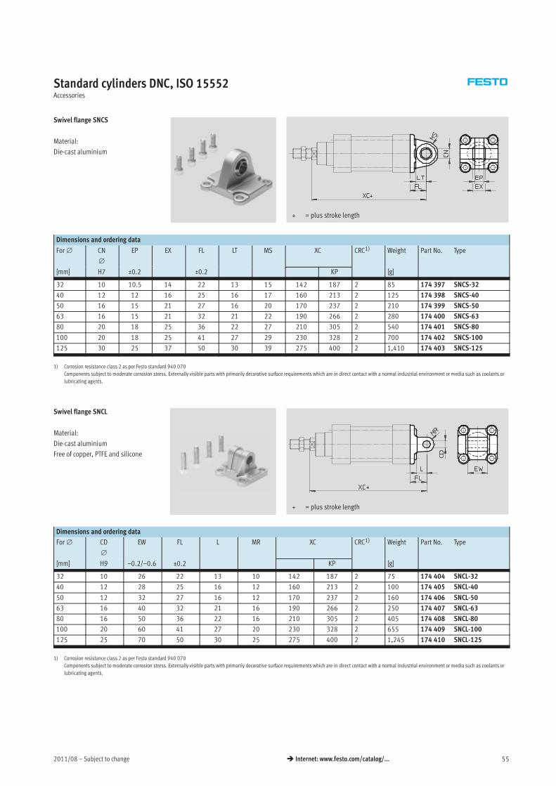
2011/08 – Subject to change 55� Internet: www.festo.com/catalog/...
Standard cylinders DNC, ISO 15552Accessories
Swivel flange SNCS
Material:
Die-cast aluminium
+ = plus stroke length
Dimensions and ordering data
For∅ CN
∅
EP EX FL LT MS XC CRC1) Weight Part No. Type
[mm] H7 ±0.2 ±0.2 KP [g]
32 10 10.5 14 22 13 15 142 187 2 85 174 397 SNCS-32
40 12 12 16 25 16 17 160 213 2 125 174 398 SNCS-40
50 16 15 21 27 16 20 170 237 2 210 174 399 SNCS-50
63 16 15 21 32 21 22 190 266 2 280 174 400 SNCS-63
80 20 18 25 36 22 27 210 305 2 540 174 401 SNCS-80
100 20 18 25 41 27 29 230 328 2 700 174 402 SNCS-100
125 30 25 37 50 30 39 275 400 2 1,410 174 403 SNCS-125
1) Corrosion resistance class 2 as per Festo standard 940 070
Components subject to moderate corrosion stress. Externally visible parts with primarily decorative surface requirements which are in direct contact with a normal industrial environment or media such as coolants or
lubricating agents.
Swivel flange SNCL
Material:
Die-cast aluminium
Free of copper, PTFE and silicone
+ = plus stroke length
Dimensions and ordering data
For∅ CD
∅
EW FL L MR XC CRC1) Weight Part No. Type
[mm] H9 –0.2/–0.6 ±0.2 KP [g]
32 10 26 22 13 10 142 187 2 75 174 404 SNCL-32
40 12 28 25 16 12 160 213 2 100 174 405 SNCL-40
50 12 32 27 16 12 170 237 2 160 174 406 SNCL-50
63 16 40 32 21 16 190 266 2 250 174 407 SNCL-63
80 16 50 36 22 16 210 305 2 405 174 408 SNCL-80
100 20 60 41 27 20 230 328 2 655 174 409 SNCL-100
125 25 70 50 30 25 275 400 2 1,245 174 410 SNCL-125
1) Corrosion resistance class 2 as per Festo standard 940 070
Components subject to moderate corrosion stress. Externally visible parts with primarily decorative surface requirements which are in direct contact with a normal industrial environment or media such as coolants or
lubricating agents.
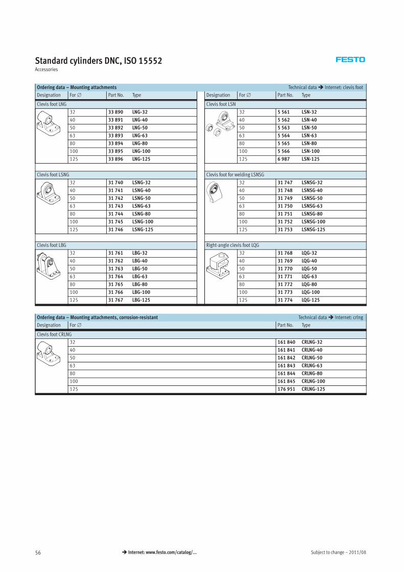
Subject to change – 2011/0856 � Internet: www.festo.com/catalog/...
Standard cylinders DNC, ISO 15552Accessories
Ordering data – Mounting attachments Technical data� Internet: clevis foot
Designation For∅ Part No. Type Designation For∅ Part No. Type
Clevis foot LNG Clevis foot LSN
32 33 890 LNG-32 32 5 561 LSN-32
40 33 891 LNG-40 40 5 562 LSN-40
50 33 892 LNG-50 50 5 563 LSN-50
63 33 893 LNG-63 63 5 564 LSN-63
80 33 894 LNG-80 80 5 565 LSN-80
100 33 895 LNG-100 100 5 566 LSN-100
125 33 896 LNG-125 125 6 987 LSN-125
Clevis foot LSNG Clevis foot for welding LSNSG
32 31 740 LSNG-32 32 31 747 LSNSG-32
40 31 741 LSNG-40 40 31 748 LSNSG-40
50 31 742 LSNG-50 50 31 749 LSNSG-50
63 31 743 LSNG-63 63 31 750 LSNSG-63
80 31 744 LSNG-80 80 31 751 LSNSG-80
100 31 745 LSNG-100 100 31 752 LSNSG-100
125 31 746 LSNG-125 125 31 753 LSNSG-125
Clevis foot LBG Right-angle clevis foot LQG
32 31 761 LBG-32 32 31 768 LQG-32
40 31 762 LBG-40 40 31 769 LQG-40
50 31 763 LBG-50 50 31 770 LQG-50
63 31 764 LBG-63 63 31 771 LQG-63
80 31 765 LBG-80 80 31 772 LQG-80
100 31 766 LBG-100 100 31 773 LQG-100
125 31 767 LBG-125 125 31 774 LQG-125
Ordering data – Mounting attachments, corrosion-resistant Technical data� Internet: crlng
Designation For∅ Part No. Type
Clevis foot CRLNG
32 161 840 CRLNG-32
40 161 841 CRLNG-40
50 161 842 CRLNG-50
63 161 843 CRLNG-63
80 161 844 CRLNG-80
100 161 845 CRLNG-100
125 176 951 CRLNG-125
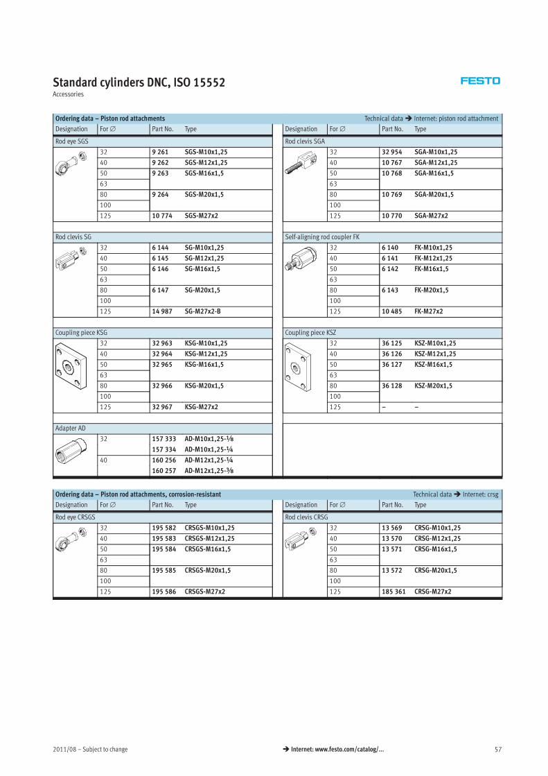
2011/08 – Subject to change 57� Internet: www.festo.com/catalog/...
Standard cylinders DNC, ISO 15552Accessories
Ordering data – Piston rod attachments Technical data� Internet: piston rod attachment
Designation For∅ Part No. Type Designation For∅ Part No. Type
Rod eye SGS Rod clevis SGA
32 9 261 SGS-M10x1,25 32 32 954 SGA-M10x1,25
40 9 262 SGS-M12x1,25 40 10 767 SGA-M12x1,25
50 9 263 SGS-M16x1,5 50 10 768 SGA-M16x1,5
63 63
80 9 264 SGS-M20x1,5 80 10 769 SGA-M20x1,5
100 100
125 10 774 SGS-M27x2 125 10 770 SGA-M27x2
Rod clevis SG Self-aligning rod coupler FK
32 6 144 SG-M10x1,25 32 6 140 FK-M10x1,25
40 6 145 SG-M12x1,25 40 6 141 FK-M12x1,25
50 6 146 SG-M16x1,5 50 6 142 FK-M16x1,5
63 63
80 6 147 SG-M20x1,5 80 6 143 FK-M20x1,5
100 100
125 14 987 SG-M27x2-B 125 10 485 FK-M27x2
Coupling piece KSG Coupling piece KSZ
32 32 963 KSG-M10x1,25 32 36 125 KSZ-M10x1,25
40 32 964 KSG-M12x1,25 40 36 126 KSZ-M12x1,25
50 32 965 KSG-M16x1,5 50 36 127 KSZ-M16x1,5
63 63
80 32 966 KSG-M20x1,5 80 36 128 KSZ-M20x1,5
100 100
125 32 967 KSG-M27x2 125 – –
Adapter AD
32 157 333 AD-M10x1,25-x
157 334 AD-M10x1,25-¼
40 160 256 AD-M12x1,25-¼
160 257 AD-M12x1,25-y
Ordering data – Piston rod attachments, corrosion-resistant Technical data� Internet: crsg
Designation For∅ Part No. Type Designation For∅ Part No. Type
Rod eye CRSGS Rod clevis CRSG
32 195 582 CRSGS-M10x1,25 32 13 569 CRSG-M10x1,25
40 195 583 CRSGS-M12x1,25 40 13 570 CRSG-M12x1,25
50 195 584 CRSGS-M16x1,5 50 13 571 CRSG-M16x1,5
63 63
80 195 585 CRSGS-M20x1,5 80 13 572 CRSG-M20x1,5
100 100
125 195 586 CRSGS-M27x2 125 185 361 CRSG-M27x2
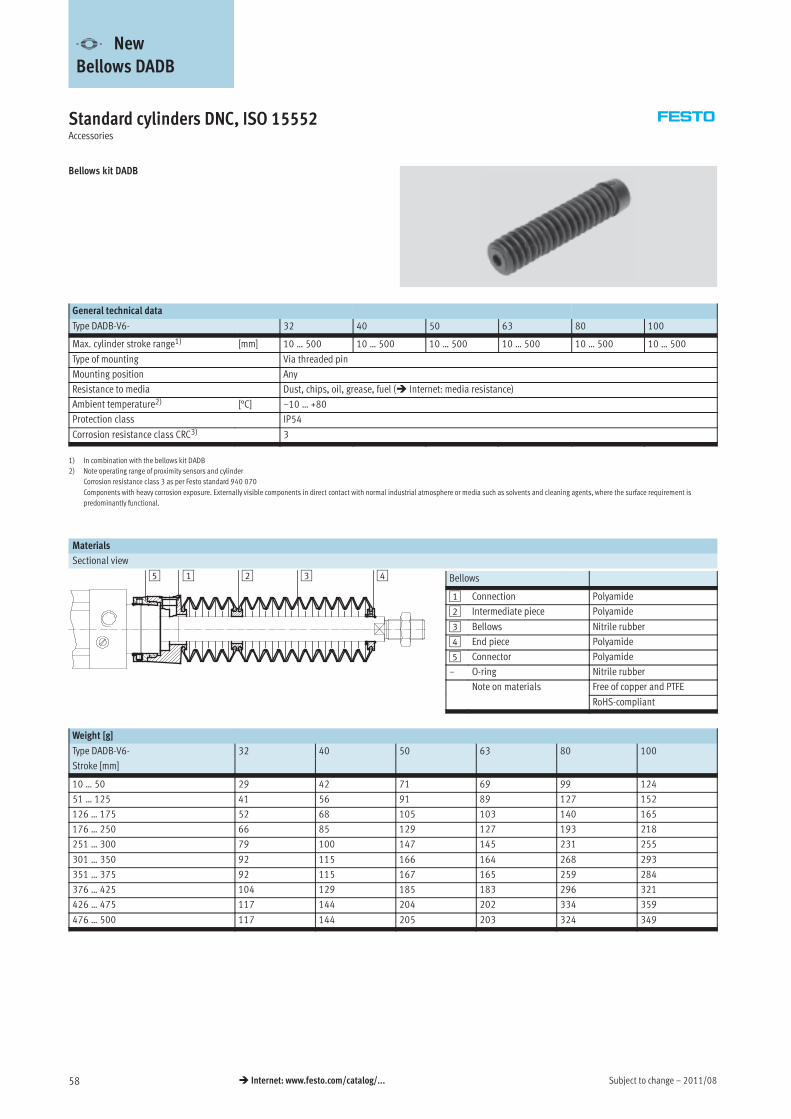
Subject to change – 2011/0858 � Internet: www.festo.com/catalog/...
Standard cylinders DNC, ISO 15552Accessories
Bellows kit DADB
General technical data
Type DADB-V6- 32 40 50 63 80 100
Max. cylinder stroke range1) [mm] 10 … 500 10 … 500 10 … 500 10 … 500 10 … 500 10 … 500
Type of mounting Via threaded pin
Mounting position Any
Resistance to media Dust, chips, oil, grease, fuel (� Internet: media resistance)
Ambient temperature2) [°C] –10 … +80
Protection class IP54
Corrosion resistance class CRC3) 3
1) In combination with the bellows kit DADB
2) Note operating range of proximity sensors and cylinder
Corrosion resistance class 3 as per Festo standard 940 070
Components with heavy corrosion exposure. Externally visible components in direct contact with normal industrial atmosphere or media such as solvents and cleaning agents, where the surface requirement is
predominantly functional.
Materials
Sectional view
Bellows
1 Connection Polyamide
2 Intermediate piece Polyamide
3 Bellows Nitrile rubber
4 End piece Polyamide
5 Connector Polyamide
– O-ring Nitrile rubber
Note on materials Free of copper and PTFE
RoHS-compliant
Weight [g]
Type DADB-V6- 32 40 50 63 80 100
Stroke [mm]
10 … 50 29 42 71 69 99 124
51 … 125 41 56 91 89 127 152
126 … 175 52 68 105 103 140 165
176 … 250 66 85 129 127 193 218
251 … 300 79 100 147 145 231 255
301 … 350 92 115 166 164 268 293
351 … 375 92 115 167 165 259 284
376 … 425 104 129 185 183 296 321
426 … 475 117 144 204 202 334 359
476 … 500 117 144 205 203 324 349
-V- New
Bellows DADB
2 31 45
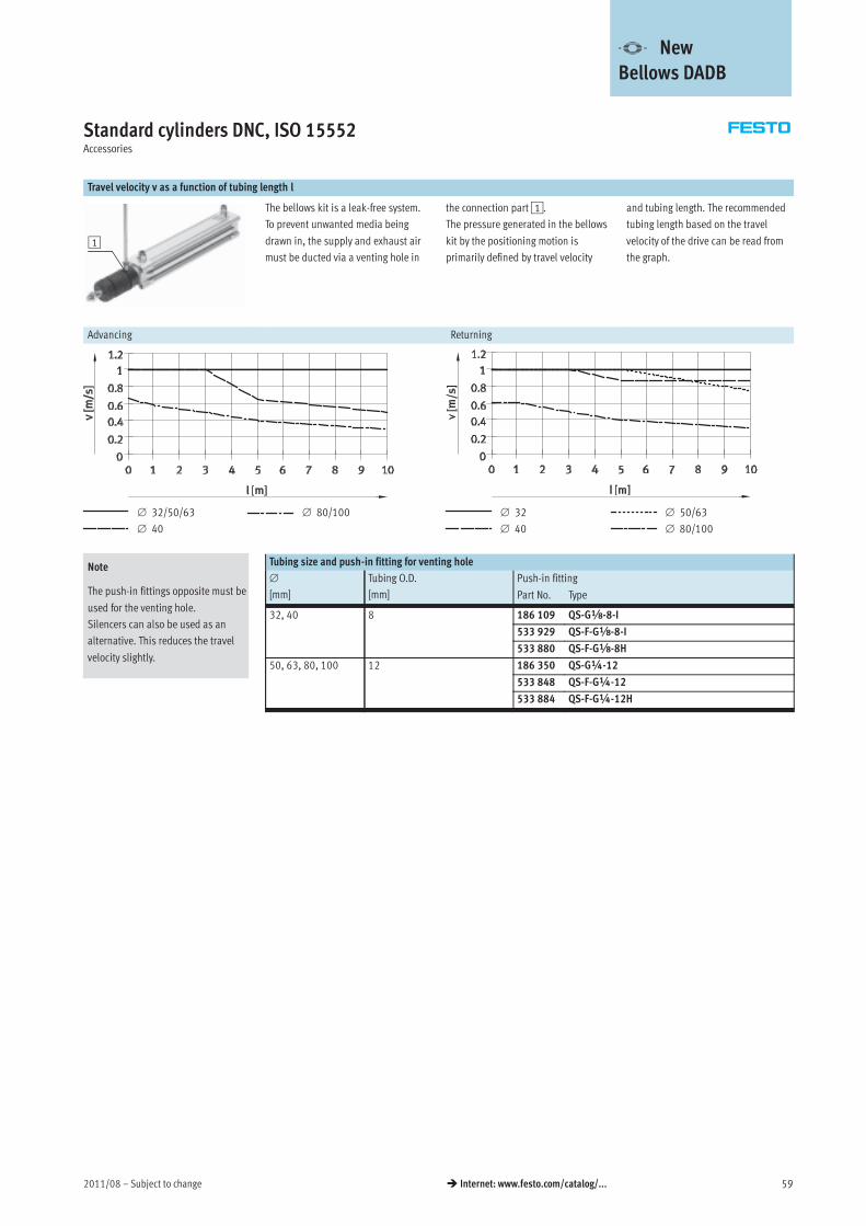
2011/08 – Subject to change 59� Internet: www.festo.com/catalog/...
Standard cylinders DNC, ISO 15552Accessories
Travel velocity v as a function of tubing length l
1
The bellows kit is a leak-free system.
To prevent unwanted media being
drawn in, the supply and exhaust air
must be ducted via a venting hole in
the connection part1.
The pressure generated in the bellows
kit by the positioning motion is
primarily defined by travel velocity
and tubing length. The recommended
tubing length based on the travel
velocity of the drive can be read from
the graph.
Advancing Returning
∅ 32/50/63
∅ 40
∅ 80/100 ∅ 32
∅ 40
∅ 50/63
∅ 80/100
Tubing size and push-in fitting for venting hole
∅
[mm]
Tubing O.D.
[mm]
Push-in fitting
Part No. Type
32, 40 8 186 109 QS-Gx-8-I
533 929 QS-F-Gx-8-I
533 880 QS-F-Gx-8H
50, 63, 80, 100 12 186 350 QS-G¼-12
533 848 QS-F-G¼-12
533 884 QS-F-G¼-12H
-V- New
Bellows DADB
Note
The push-in fittings opposite must be
used for the venting hole.
Silencers can also be used as an
alternative. This reduces the travel
velocity slightly.
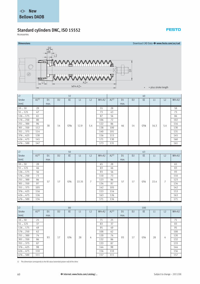
Subject to change – 2011/0860 � Internet: www.festo.com/catalog/...
Standard cylinders DNC, ISO 15552Accessories
Dimensions Download CAD Data� www.festo.com/us/cad
+ = plus stroke length
∅ 32 40
Stroke A21) D1 D2 EE L1 L2 WH+A2 A21) D1 D2 EE L1 L2 WH+A2
[mm] max. max.
10 … 50 29
38 14 Gx 12.9 5.4
55 28
46 14 Gx 16.3 5.4
58
51 … 125 47 73 43 73
126 … 175 61 87 56 86
176 … 250 80 106 72 102
251 … 300 96 122 86 116
301 … 350 112 138 100 130
351 … 375 114 140 101 131
376 … 425 130 156 115 145
426 … 475 145 171 130 160
476 … 500 147 173 131 161
∅ 50 63
Stroke A21) D1 D2 EE L1 L2 WH+A2 A21) D1 D2 EE L1 L2 WH+A2
[mm] max. max.
10 … 50 28
57 17 G¼ 22.35 7
65 28
57 17 G¼ 22.4 7
65
51 … 125 46 83 46 83
126 … 175 56 93 56 93
176 … 250 73 110 73 110
251 … 300 86 123 86 123
301 … 350 97 134 97 134
351 … 375 105 142 105 142
376 … 425 116 153 116 153
426 … 475 126 163 126 163
476 … 500 134 171 134 171
∅ 80 100
Stroke A21) D1 D2 EE L1 L2 WH+A2 A21) D1 D2 EE L1 L2 WH+A2
[mm] max. max.
10 … 50 25
93 17 G¼ 28 4
71 25
93 17 G¼ 28 4
71
51 … 125 37 83 37 83
126 … 175 49 95 49 95
176 … 250 62 108 62 108
251 … 300 74 120 74 120
301 … 350 86 132 86 132
351 … 375 87 133 87 133
376 … 425 98 144 98 144
426 … 475 110 156 110 156
476 … 500 111 157 111 157
1) The dimension corresponds to the K8 value (extended piston rod) of the drive
-V- New
Bellows DADB
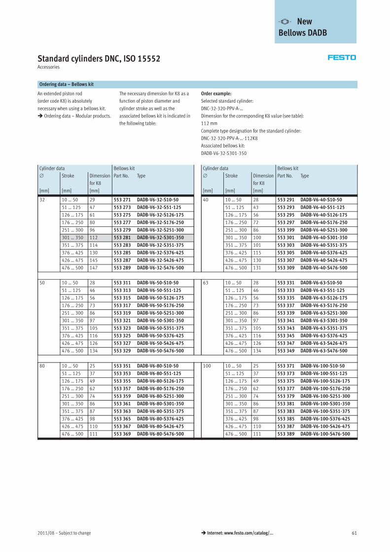
2011/08 – Subject to change 61� Internet: www.festo.com/catalog/...
Standard cylinders DNC, ISO 15552Accessories
Ordering data – Bellows kit
An extended piston rod
(order code K8) is absolutely
necessary when using a bellows kit.
� Ordering data – Modular products.
The necessary dimension for K8 as a
function of piston diameter and
cylinder stroke as well as the
associated bellows kit is indicated in
the following table:
Order example:
Selected standard cylinder:
DNC-32-320-PPV-A-…
Dimension for the corresponding K8 value (see table):
112 mm
Complete type designation for the standard cylinder:
DNC-32-320-PPV-A-…-112K8
Associated bellows kit:
DADB-V6-32-S301-350
Cylinder data Bellows kit Cylinder data Bellows kit
∅
[mm]
Stroke
[mm]
Dimension
for K8
[mm]
Part No. Type ∅
[mm]
Stroke
[mm]
Dimension
for K8
[mm]
Part No. Type
32 10 … 50 29 553 271 DADB-V6-32-S10-50 40 10 … 50 28 553 291 DADB-V6-40-S10-50
51 … 125 47 553 273 DADB-V6-32-S51-125 51 … 125 43 553 293 DADB-V6-40-S51-125
126 … 175 61 553 275 DADB-V6-32-S126-175 126 … 175 56 553 295 DADB-V6-40-S126-175
176 … 250 80 553 277 DADB-V6-32-S176-250 176 … 250 72 553 297 DADB-V6-40-S176-250
251 … 300 96 553 279 DADB-V6-32-S251-300 251 … 300 86 553 399 DADB-V6-40-S251-300
301 … 350 112 553 281 DADB-V6-32-S301-350 301 … 350 100 553 301 DADB-V6-40-S301-350
351 … 375 114 553 283 DADB-V6-32-S351-375 351 … 375 101 553 303 DADB-V6-40-S351-375
376 … 425 130 553 285 DADB-V6-32-S376-425 376 … 425 115 553 305 DADB-V6-40-S376-425
426 … 475 145 553 287 DADB-V6-32-S426-475 426 … 475 130 553 307 DADB-V6-40-S426-475
476 … 500 147 553 289 DADB-V6-32-S476-500 476 … 500 131 553 309 DADB-V6-40-S476-500
50 10 … 50 28 553 311 DADB-V6-50-S10-50 63 10 … 50 28 553 331 DADB-V6-63-S10-50
51 … 125 46 553 313 DADB-V6-50-S51-125 51 … 125 46 553 333 DADB-V6-63-S51-125
126 … 175 56 553 315 DADB-V6-50-S126-175 126 … 175 56 553 335 DADB-V6-63-S126-175
176 … 250 73 553 317 DADB-V6-50-S176-250 176 … 250 73 553 337 DADB-V6-63-S176-250
251 … 300 86 553 319 DADB-V6-50-S251-300 251 … 300 86 553 339 DADB-V6-63-S251-300
301 … 350 97 553 321 DADB-V6-50-S301-350 301 … 350 97 553 341 DADB-V6-63-S301-350
351 … 375 105 553 323 DADB-V6-50-S351-375 351 … 375 105 553 343 DADB-V6-63-S351-375
376 … 425 116 553 325 DADB-V6-50-S376-425 376 … 425 116 553 345 DADB-V6-63-S376-425
426 … 475 126 553 327 DADB-V6-50-S426-475 426 … 475 126 553 347 DADB-V6-63-S426-475
476 … 500 134 553 329 DADB-V6-50-S476-500 476 … 500 134 553 349 DADB-V6-63-S476-500
80 10 … 50 25 553 351 DADB-V6-80-S10-50 100 10 … 50 25 553 371 DADB-V6-100-S10-50
51 … 125 37 553 353 DADB-V6-80-S51-125 51 … 125 37 553 373 DADB-V6-100-S51-125
126 … 175 49 553 355 DADB-V6-80-S126-175 126 … 175 49 553 375 DADB-V6-100-S126-175
176 … 250 62 553 357 DADB-V6-80-S176-250 176 … 250 62 553 377 DADB-V6-100-S176-250
251 … 300 74 553 359 DADB-V6-80-S251-300 251 … 300 74 553 379 DADB-V6-100-S251-300
301 … 350 86 553 361 DADB-V6-80-S301-350 301 … 350 86 553 381 DADB-V6-100-S301-350
351 … 375 87 553 363 DADB-V6-80-S351-375 351 … 375 87 553 383 DADB-V6-100-S351-375
376 … 425 98 553 365 DADB-V6-80-S376-425 376 … 425 98 553 385 DADB-V6-100-S376-425
426 … 475 110 553 367 DADB-V6-80-S426-475 426 … 475 110 553 387 DADB-V6-100-S426-475
476 … 500 111 553 369 DADB-V6-80-S476-500 476 … 500 111 553 389 DADB-V6-100-S476-500
-V- New
Bellows DADB
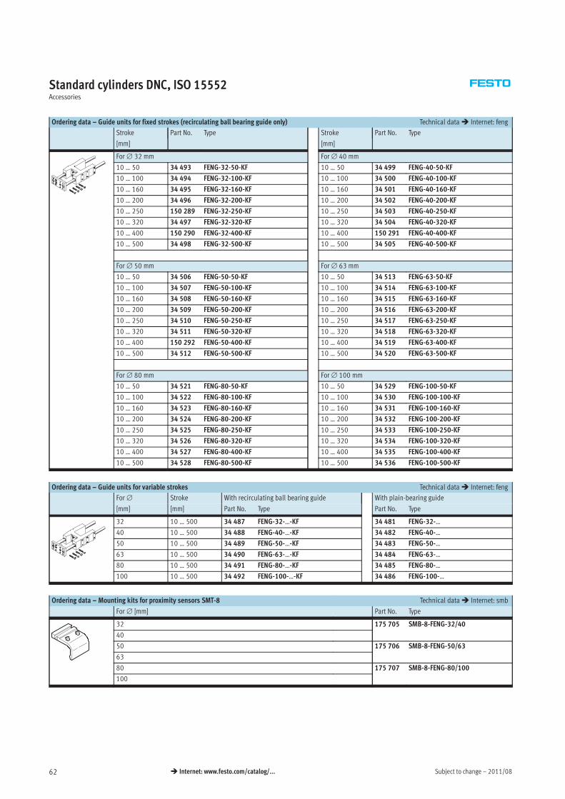
Subject to change – 2011/0862 � Internet: www.festo.com/catalog/...
Standard cylinders DNC, ISO 15552Accessories
Ordering data – Guide units for fixed strokes (recirculating ball bearing guide only) Technical data� Internet: feng
Stroke Part No. Type Stroke Part No. Type
[mm] [mm]
For∅ 32 mm For∅ 40 mm
10 … 50 34 493 FENG-32-50-KF 10 … 50 34 499 FENG-40-50-KF
10 … 100 34 494 FENG-32-100-KF 10 … 100 34 500 FENG-40-100-KF
10 … 160 34 495 FENG-32-160-KF 10 … 160 34 501 FENG-40-160-KF
10 … 200 34 496 FENG-32-200-KF 10 … 200 34 502 FENG-40-200-KF
10 … 250 150 289 FENG-32-250-KF 10 … 250 34 503 FENG-40-250-KF
10 … 320 34 497 FENG-32-320-KF 10 … 320 34 504 FENG-40-320-KF
10 … 400 150 290 FENG-32-400-KF 10 … 400 150 291 FENG-40-400-KF
10 … 500 34 498 FENG-32-500-KF 10 … 500 34 505 FENG-40-500-KF
For∅ 50 mm For∅ 63 mm
10 … 50 34 506 FENG-50-50-KF 10 … 50 34 513 FENG-63-50-KF
10 … 100 34 507 FENG-50-100-KF 10 … 100 34 514 FENG-63-100-KF
10 … 160 34 508 FENG-50-160-KF 10 … 160 34 515 FENG-63-160-KF
10 … 200 34 509 FENG-50-200-KF 10 … 200 34 516 FENG-63-200-KF
10 … 250 34 510 FENG-50-250-KF 10 … 250 34 517 FENG-63-250-KF
10 … 320 34 511 FENG-50-320-KF 10 … 320 34 518 FENG-63-320-KF
10 … 400 150 292 FENG-50-400-KF 10 … 400 34 519 FENG-63-400-KF
10 … 500 34 512 FENG-50-500-KF 10 … 500 34 520 FENG-63-500-KF
For∅ 80 mm For∅ 100 mm
10 … 50 34 521 FENG-80-50-KF 10 … 50 34 529 FENG-100-50-KF
10 … 100 34 522 FENG-80-100-KF 10 … 100 34 530 FENG-100-100-KF
10 … 160 34 523 FENG-80-160-KF 10 … 160 34 531 FENG-100-160-KF
10 … 200 34 524 FENG-80-200-KF 10 … 200 34 532 FENG-100-200-KF
10 … 250 34 525 FENG-80-250-KF 10 … 250 34 533 FENG-100-250-KF
10 … 320 34 526 FENG-80-320-KF 10 … 320 34 534 FENG-100-320-KF
10 … 400 34 527 FENG-80-400-KF 10 … 400 34 535 FENG-100-400-KF
10 … 500 34 528 FENG-80-500-KF 10 … 500 34 536 FENG-100-500-KF
Ordering data – Guide units for variable strokes Technical data� Internet: feng
For∅ Stroke With recirculating ball bearing guide With plain-bearing guide
[mm] [mm] Part No. Type Part No. Type
32 10 … 500 34 487 FENG-32-…-KF 34 481 FENG-32-…
40 10 … 500 34 488 FENG-40-…-KF 34 482 FENG-40-…
50 10 … 500 34 489 FENG-50-…-KF 34 483 FENG-50-…
63 10 … 500 34 490 FENG-63-…-KF 34 484 FENG-63-…
80 10 … 500 34 491 FENG-80-…-KF 34 485 FENG-80-…
100 10 … 500 34 492 FENG-100-…-KF 34 486 FENG-100-…
Ordering data – Mounting kits for proximity sensors SMT-8 Technical data� Internet: smb
For∅ [mm] Part No. Type
32 175 705 SMB-8-FENG-32/40
40
50 175 706 SMB-8-FENG-50/63
63
80 175 707 SMB-8-FENG-80/100
100
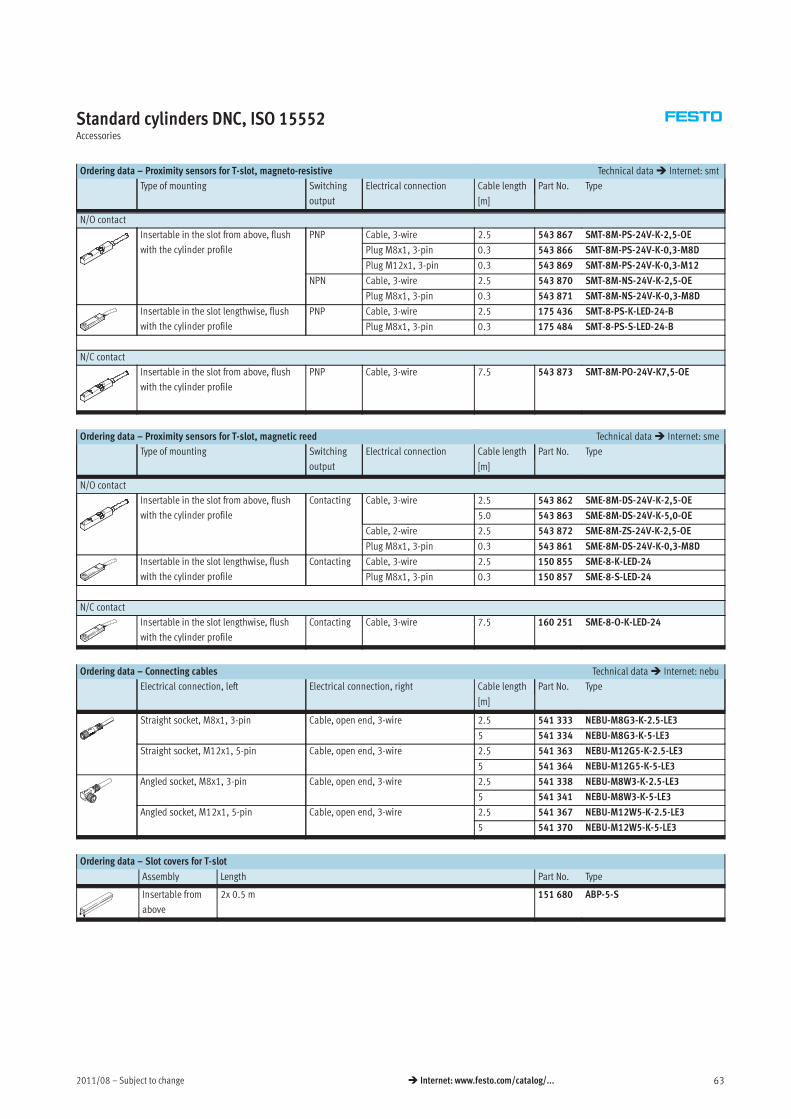
2011/08 – Subject to change 63� Internet: www.festo.com/catalog/...
Standard cylinders DNC, ISO 15552Accessories
Ordering data – Proximity sensors for T-slot, magneto-resistive Technical data� Internet: smt
Type of mounting Switching
output
Electrical connection Cable length Part No. Type
[m]
N/O contact
Insertable in the slot from above, flush
with the cylinder profile
PNP Cable, 3-wire 2.5 543 867 SMT-8M-PS-24V-K-2,5-OE
Plug M8x1, 3-pin 0.3 543 866 SMT-8M-PS-24V-K-0,3-M8D
Plug M12x1, 3-pin 0.3 543 869 SMT-8M-PS-24V-K-0,3-M12
NPN Cable, 3-wire 2.5 543 870 SMT-8M-NS-24V-K-2,5-OE
Plug M8x1, 3-pin 0.3 543 871 SMT-8M-NS-24V-K-0,3-M8D
Insertable in the slot lengthwise, flush
with the cylinder profile
PNP Cable, 3-wire 2.5 175 436 SMT-8-PS-K-LED-24-B
Plug M8x1, 3-pin 0.3 175 484 SMT-8-PS-S-LED-24-B
N/C contact
Insertable in the slot from above, flush
with the cylinder profile
PNP Cable, 3-wire 7.5 543 873 SMT-8M-PO-24V-K7,5-OE
Ordering data – Proximity sensors for T-slot, magnetic reed Technical data� Internet: sme
Type of mounting Switching
output
Electrical connection Cable length Part No. Type
[m]
N/O contact
Insertable in the slot from above, flush
with the cylinder profile
Contacting Cable, 3-wire 2.5 543 862 SME-8M-DS-24V-K-2,5-OE
5.0 543 863 SME-8M-DS-24V-K-5,0-OE
Cable, 2-wire 2.5 543 872 SME-8M-ZS-24V-K-2,5-OE
Plug M8x1, 3-pin 0.3 543 861 SME-8M-DS-24V-K-0,3-M8D
Insertable in the slot lengthwise, flush
with the cylinder profile
Contacting Cable, 3-wire 2.5 150 855 SME-8-K-LED-24
Plug M8x1, 3-pin 0.3 150 857 SME-8-S-LED-24
N/C contact
Insertable in the slot lengthwise, flush
with the cylinder profile
Contacting Cable, 3-wire 7.5 160 251 SME-8-O-K-LED-24
Ordering data – Connecting cables Technical data� Internet: nebu
Electrical connection, left Electrical connection, right Cable length Part No. Type
[m]
Straight socket, M8x1, 3-pin Cable, open end, 3-wire 2.5 541 333 NEBU-M8G3-K-2.5-LE3
5 541 334 NEBU-M8G3-K-5-LE3
Straight socket, M12x1, 5-pin Cable, open end, 3-wire 2.5 541 363 NEBU-M12G5-K-2.5-LE3
5 541 364 NEBU-M12G5-K-5-LE3
Angled socket, M8x1, 3-pin Cable, open end, 3-wire 2.5 541 338 NEBU-M8W3-K-2.5-LE3
5 541 341 NEBU-M8W3-K-5-LE3
Angled socket, M12x1, 5-pin Cable, open end, 3-wire 2.5 541 367 NEBU-M12W5-K-2.5-LE3
5 541 370 NEBU-M12W5-K-5-LE3
Ordering data – Slot covers for T-slot
Assembly Length Part No. Type
Insertable from
above
2x 0.5 m 151 680 ABP-5-S
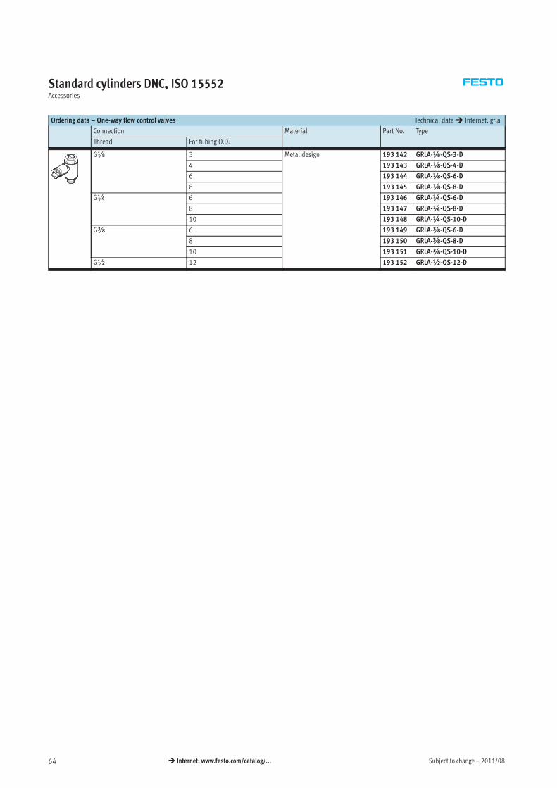
Subject to change – 2011/0864 � Internet: www.festo.com/catalog/...
Standard cylinders DNC, ISO 15552Accessories
Ordering data – One-way flow control valves Technical data� Internet: grla
Connection Material Part No. Type
Thread For tubing O.D.
Gx 3 Metal design 193 142 GRLA-x-QS-3-D
4 193 143 GRLA-x-QS-4-D
6 193 144 GRLA-x-QS-6-D
8 193 145 GRLA-x-QS-8-D
G¼ 6 193 146 GRLA-¼-QS-6-D
8 193 147 GRLA-¼-QS-8-D
10 193 148 GRLA-¼-QS-10-D
Gy 6 193 149 GRLA-y-QS-6-D
8 193 150 GRLA-y-QS-8-D
10 193 151 GRLA-y-QS-10-D
G½ 12 193 152 GRLA-½-QS-12-D
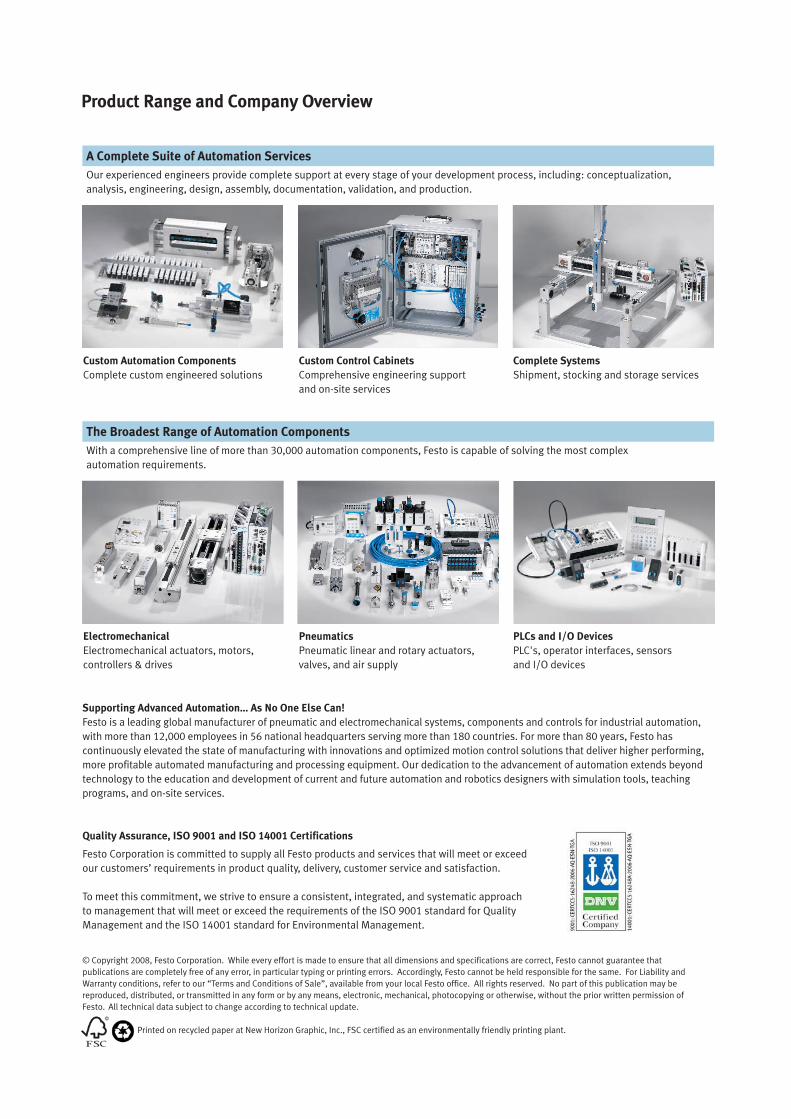
Product Range and Company Overview
The Broadest Range of Automation Components
With a comprehensive line of more than 30,000 automation components, Festo is capable of solving the most complex
automation requirements.
Supporting Advanced Automation… As No One Else Can!
Festo is a leading global manufacturer of pneumatic and electromechanical systems, components and controls for industrial automation,
with more than 12,000 employees in 56 national headquarters serving more than 180 countries. For more than 80 years, Festo has
continuously elevated the state of manufacturing with innovations and optimized motion control solutions that deliver higher performing,
more profitable automated manufacturing and processing equipment. Our dedication to the advancement of automation extends beyond
technology to the education and development of current and future automation and robotics designers with simulation tools, teaching
programs, and on-site services.
Quality Assurance, ISO 9001 and ISO 14001 Certifications
Festo Corporation is committed to supply all Festo products and services that will meet or exceed
our customers’ requirements in product quality, delivery, customer service and satisfaction.
To meet this commitment, we strive to ensure a consistent, integrated, and systematic approach
to management that will meet or exceed the requirements of the ISO 9001 standard for Quality
Management and the ISO 14001 standard for Environmental Management.
PLCs and I/O Devices
PLC's, operator interfaces, sensors
and I/O devices
Pneumatics
Pneumatic linear and rotary actuators,
valves, and air supply
Electromechanical
Electromechanical actuators, motors,
controllers & drives
A Complete Suite of Automation Services
Our experienced engineers provide complete support at every stage of your development process, including: conceptualization,
analysis, engineering, design, assembly, documentation, validation, and production.
Complete Systems
Shipment, stocking and storage services
Custom Control Cabinets
Comprehensive engineering support
and on-site services
Custom Automation Components
Complete custom engineered solutions
© Copyright 2008, Festo Corporation. While every effort is made to ensure that all dimensions and specifications are correct, Festo cannot guarantee that
publications are completely free of any error, in particular typing or printing errors. Accordingly, Festo cannot be held responsible for the same. For Liability and
Warranty conditions, refer to our “Terms and Conditions of Sale”, available from your local Festo office. All rights reserved. No part of this publication may be
reproduced, distributed, or transmitted in any form or by any means, electronic, mechanical, photocopying or otherwise, without the prior written permission of
Festo. All technical data subject to change according to technical update.
Printed on recycled paper at New Horizon Graphic, Inc., FSC certified as an environmentally friendly printing plant.
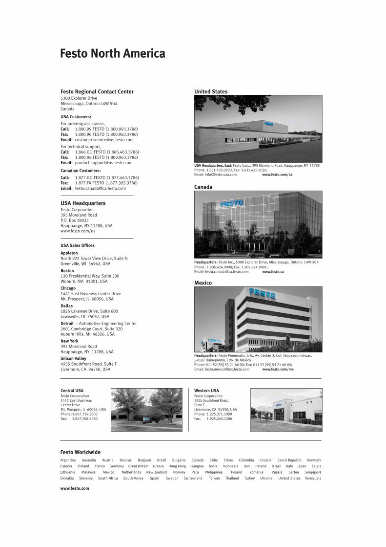
Festo Regional Contact Center5300 Explorer DriveMississauga, Ontario L4W 5G4Canada
USA Customers:
For ordering assistance,Call: 1.800.99.FESTO (1.800.993.3786)Fax: 1.800.96.FESTO (1.800.963.3786)Email: [email protected]
For technical support,Call: 1.866.GO.FESTO (1.866.463.3786)Fax: 1.800.96.FESTO (1.800.963.3786)Email: [email protected]
Canadian Customers:
Call: 1.877.GO.FESTO (1.877.463.3786)Fax: 1.877.FX.FESTO (1.877.393.3786)Email: [email protected]
USA HeadquartersFesto Corporation395 Moreland RoadP.O. Box 18023Hauppauge, NY 11788, USAwww.festo.com/us
USA Sales Offices
AppletonNorth 922 Tower View Drive, Suite NGreenville, WI 54942, USA
Boston120 Presidential Way, Suite 330Woburn, MA 01801, USA
Chicago1441 East Business Center DriveMt. Prospect, IL 60056, USA
Dallas1825 Lakeway Drive, Suite 600Lewisville, TX 75057, USA
Detroit – Automotive Engineering Center2601 Cambridge Court, Suite 320Auburn Hills, MI 48326, USA
New York395 Moreland RoadHauppauge, NY 11788, USA
Silicon Valley
4935 Southfront Road, Suite FLivermore, CA 94550, USA
Festo North America
United States
Western USAFesto Corporation4935 Southfront Road,Suite FLivermore, CA 94550, USAPhone: 1.925.371.1099Fax: 1.925.245.1286
Central USAFesto Corporation1441 East BusinessCenter DriveMt. Prospect, IL 60056, USAPhone:1.847.759.2600Fax: 1.847.768.9480
Festo Worldwide
Argentina Australia Austria Belarus Belgium Brazil Bulgaria Canada Chile China Colombia Croatia Czech Republic Denmark
Estonia Finland France Germany Great Britain Greece Hong Kong Hungary India Indonesia Iran Ireland Israel Italy Japan Latvia
Lithuania Malaysia Mexico Netherlands New Zealand Norway Peru Philippines Poland Romania Russia Serbia Singapore
Slovakia Slovenia South Africa South Korea Spain Sweden Switzerland Taiwan Thailand Turkey Ukraine United States Venezuela
www.festo.com
USA Headquarters, East: Festo Corp., 395 Moreland Road, Hauppauge, NY 11788Phone: 1.631.435.0800; Fax: 1.631.435.8026;Email: [email protected] www.festo.com/us
Headquarters: Festo Pneumatic, S.A., Av. Ceylán 3, Col. Tequesquinahuac,54020 Tlalnepantla, Edo. de MéxicoPhone:011 52 [55] 53 21 66 00; Fax: 011 52 [55] 53 21 66 65;Email: [email protected] www.festo.com/mx
Canada
Mexico
Headquarters: Festo Inc., 5300 Explorer Drive, Mississauga, Ontario L4W 5G4
Phone: 1.905.624.9000; Fax: 1.905.624.9001;Email: [email protected] www.festo.ca
Recommended