Handleiding
Notice de montage
User guide
Anleitung
Handleiding argenta® proslide Notice de montage argenta® proslide
Lees deze handleiding eerst aandachtig eer u van start gaat.
Het plaatsen van de argenta® proslide dient te gebeuren door een vakman.
Lisez cette notice attentivement avant de commencer.
Le montage de l’argenta® proslide doit être exécuté par un professionnel.
Assemblage instructies
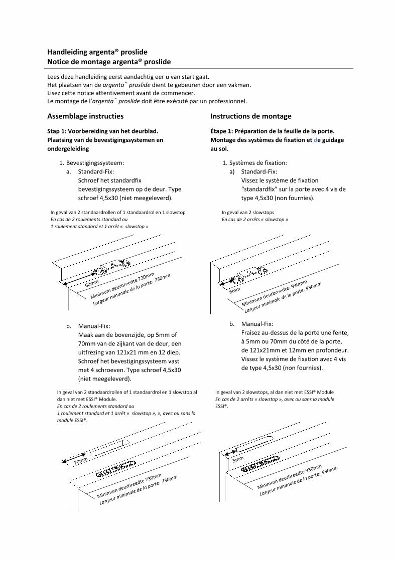
Stap 1: Voorbereiding van het deurblad.
Plaatsing van de bevestigingssystemen en
ondergeleiding
1. Bevestigingssysteem:
a. Standard-Fix:
Schroef het standardfix
bevestigingssysteem op de deur. Type
schroef 4,5x30 (niet meegeleverd).
b. Manual-Fix:
Maak aan de bovenzijde, op 5mm of
70mm van de zijkant van de deur, een
uitfrezing van 121x21 mm en 12 diep.
Schroef het bevestigingssysteem vast
met 4 schroeven. Type schroef 4,5x30
(niet meegeleverd).
Instructions de montage
Étape 1: Préparation de la feuille de la porte.
Montage des systèmes de fixation et de guidage
au sol.
1. Systèmes de fixation:
a) Standard-Fix:
Vissez le système de fixation
“standardfix” sur la porte avec 4 vis de
type 4,5x30 (non fournies).
b. Manual-Fix:
Fraisez au-dessus de la porte une fente,
à 5mm ou 70mm du côté de la porte,
de 121x21mm et 12mm en profondeur.
Vissez le système de fixation avec 4 vis
de type 4,5x30 (non fournies).
In geval van 2 slowstops
En cas de 2 arrêts « slowstop »
In geval van 2 standaardrollen of 1 standaardrol en 1 slowstop
En cas de 2 roulements standard ou
1 roulement standard et 1 arrêt « slowstop »
In geval van 2 standaardrollen of 1 standaardrol en 1 slowstop al
dan niet met ESSI® Module.
En cas de 2 roulements standard ou
1 roulement standard et 1 arrêt « slowstop », », avec ou sans la
module ESSI®.
In geval van 2 slowstops, al dan niet met ESSI® Module
En cas de 2 arrêts « slowstop », avec ou sans la module
ESSI®.
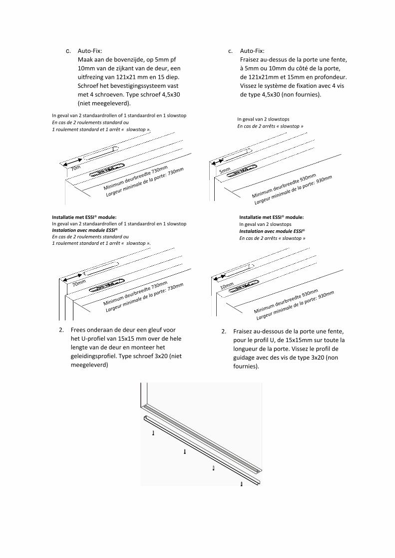
c. Auto-Fix:
Maak aan de bovenzijde, op 5mm pf
10mm van de zijkant van de deur, een
uitfrezing van 121x21 mm en 15 diep.
Schroef het bevestigingssysteem vast
met 4 schroeven. Type schroef 4,5x30
(niet meegeleverd).
2. Frees onderaan de deur een gleuf voor
het U-profiel van 15x15 mm over de hele
lengte van de deur en monteer het
geleidingsprofiel. Type schroef 3x20 (niet
meegeleverd)
c. Auto-Fix:
Fraisez au-dessus de la porte une fente,
à 5mm ou 10mm du côté de la porte,
de 121x21mm et 15mm en profondeur.
Vissez le système de fixation avec 4 vis
de type 4,5x30 (non fournies).
2. Fraisez au-dessous de la porte une fente,
pour le profil U, de 15x15mm sur toute la
longueur de la porte. Vissez le profil de
guidage avec des vis de type 3x20 (non
fournies).
In geval van 2 standaardrollen of 1 standaardrol en 1 slowstop
En cas de 2 roulements standard ou
1 roulement standard et 1 arrêt « slowstop ».
In geval van 2 slowstops
En cas de 2 arrêts « slowstop »
Installatie met ESSI® module: In geval van 2 standaardrollen of 1 standaardrol en 1 slowstop
Instalation avec module ESSI®
En cas de 2 roulements standard ou
1 roulement standard et 1 arrêt « slowstop ».
Installatie met ESSI® module:
In geval van 2 slowstops
Instalation avec module ESSI®
En cas de 2 arrêts « slowstop »
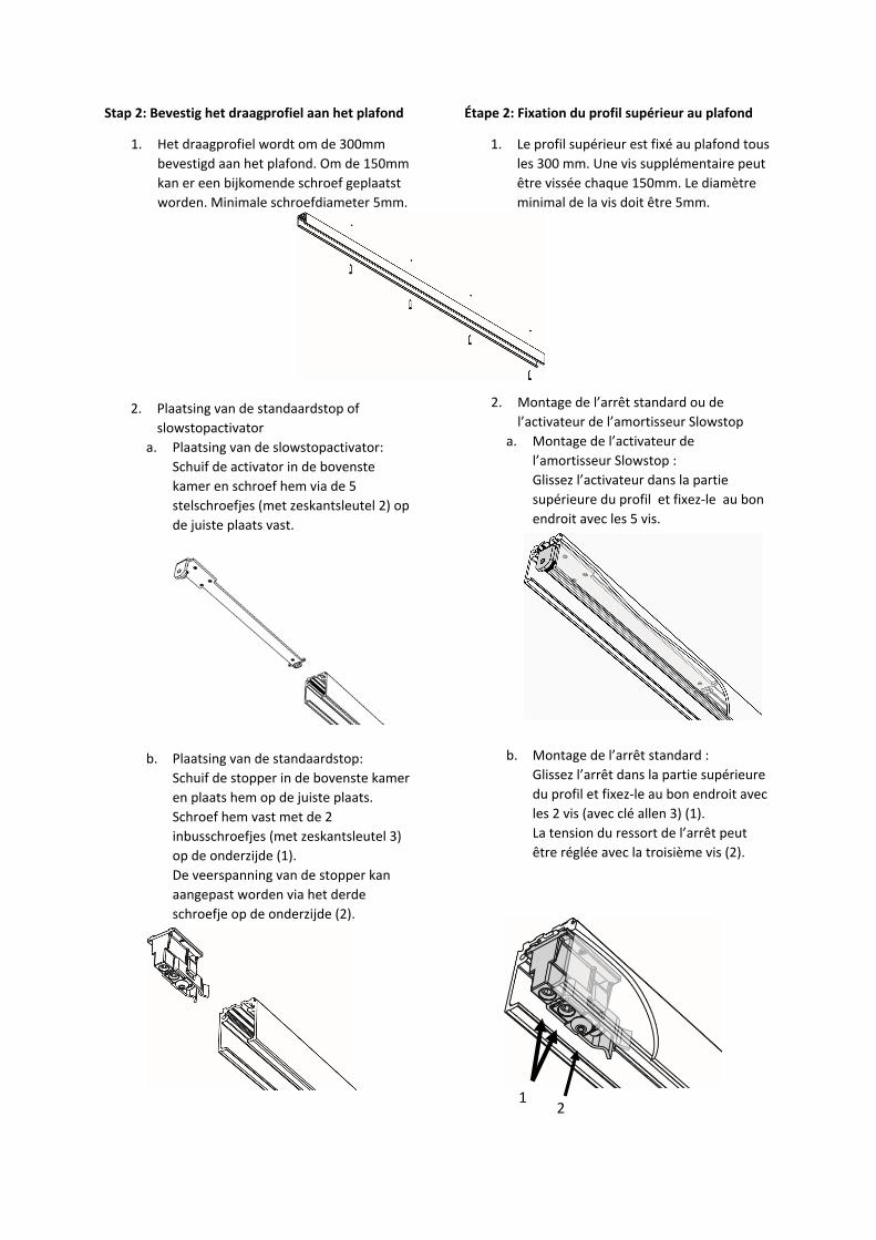
Stap 2: Bevestig het draagprofiel aan het plafond
1. Het draagprofiel wordt om de 300mm
bevestigd aan het plafond. Om de 150mm
kan er een bijkomende schroef geplaatst
worden. Minimale schroefdiameter 5mm.
2. Plaatsing van de standaardstop of
slowstopactivator
a. Plaatsing van de slowstopactivator:
Schuif de activator in de bovenste
kamer en schroef hem via de 5
stelschroefjes (met zeskantsleutel 2) op
de juiste plaats vast.
b. Plaatsing van de standaardstop:
Schuif de stopper in de bovenste kamer
en plaats hem op de juiste plaats.
Schroef hem vast met de 2
inbusschroefjes (met zeskantsleutel 3)
op de onderzijde (1).
De veerspanning van de stopper kan
aangepast worden via het derde
schroefje op de onderzijde (2).
Étape 2: Fixation du profil supérieur au plafond
1. Le profil supérieur est fixé au plafond tous
les 300 mm. Une vis supplémentaire peut
être vissée chaque 150mm. Le diamètre
minimal de la vis doit être 5mm.
2. Montage de l’arrêt standard ou de
l’activateur de l’amortisseur Slowstop
a. Montage de l’activateur de
l’amortisseur Slowstop :
Glissez l’activateur dans la partie
supérieure du profil et fixez-le au bon
endroit avec les 5 vis.
b. Montage de l’arrêt standard :
Glissez l’arrêt dans la partie supérieure
du profil et fixez-le au bon endroit avec
les 2 vis (avec clé allen 3) (1).
La tension du ressort de l’arrêt peut
être réglée avec la troisième vis (2).
1 2
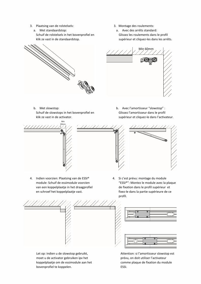
3. Plaatsing van de rolstelsels:
a. Met standaardstop:
Schuif de rolstelsels in het bovenprofiel en
klik ze vast in de standaardstop.
b. Met slowstop:
Schuif de slowstops in het bovenprofiel en
klik ze vast in de activator.
4. Indien voorzien: Plaatsing van de ESSI®
module: Schuif de essimodule voorzien
van een koppelplaatje in het draagprofiel
en schroef het koppelplaatje vast.
3. Montage des roulements:
a. Avec des arrêts standard:
Glissez les roulements dans le profil
supérieur et cliquez-les dans les arrêts.
b. Avec l’amortisseur “slowstop” :
Glissez l’amortisseur dans le profil
supérieur et cliquez-le dans l’activateur.
4. Si c’est prévu: montage du module
“ESSI®”: Montez le module avec la plaque
de fixation dans le profil supérieur et
fixez-le dans la partie supérieure de ce
profil.
é
Min
60mm
Min 60mm
Let op: indien u de slowstop gebruikt,
moet u de activator gebruiken ipv het
koppelplaatje om de essimodule aan het
bovenprofiel te koppelen.
Attention: si l’amortisseur slowstop est
prévu, on doit utiliser l’activateur
comme plaque de fixation du module
ESSI.
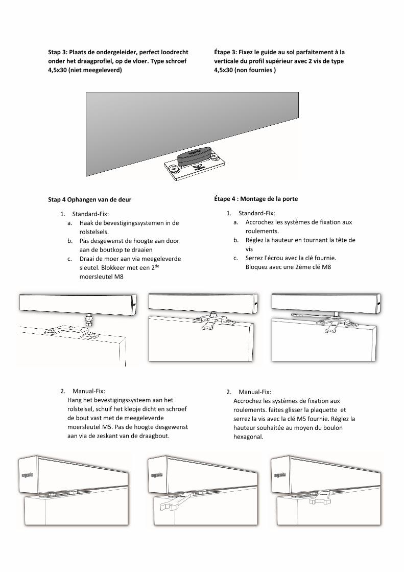
Stap 3: Plaats de ondergeleider, perfect loodrecht
onder het draagprofiel, op de vloer. Type schroef
4,5x30 (niet meegeleverd)
Stap 4 Ophangen van de deur
1. Standard-Fix:
a. Haak de bevestigingssystemen in de
rolstelsels.
b. Pas desgewenst de hoogte aan door
aan de boutkop te draaien
c. Draai de moer aan via meegeleverde
sleutel. Blokkeer met een 2de
moersleutel M8
2. Manual-Fix:
Hang het bevestigingssysteem aan het
rolstelsel, schuif het klepje dicht en schroef
de bout vast met de meegeleverde
moersleutel M5. Pas de hoogte desgewenst
aan via de zeskant van de draagbout.
Étape 3: Fixez le guide au sol parfaitement à la
verticale du profil supérieur avec 2 vis de type
4,5x30 (non fournies )
Étape 4 : Montage de la porte
1. Standard-Fix:
a. Accrochez les systèmes de fixation aux
roulements.
b. Réglez la hauteur en tournant la tête de
vis
c. Serrez l'écrou avec la clé fournie.
Bloquez avec une 2ème clé M8
2. Manual-Fix:
Accrochez les systèmes de fixation aux
roulements. faites glisser la plaquette et
serrez la vis avec la clé M5 fournie. Réglez la
hauteur souhaitée au moyen du boulon
hexagonal.
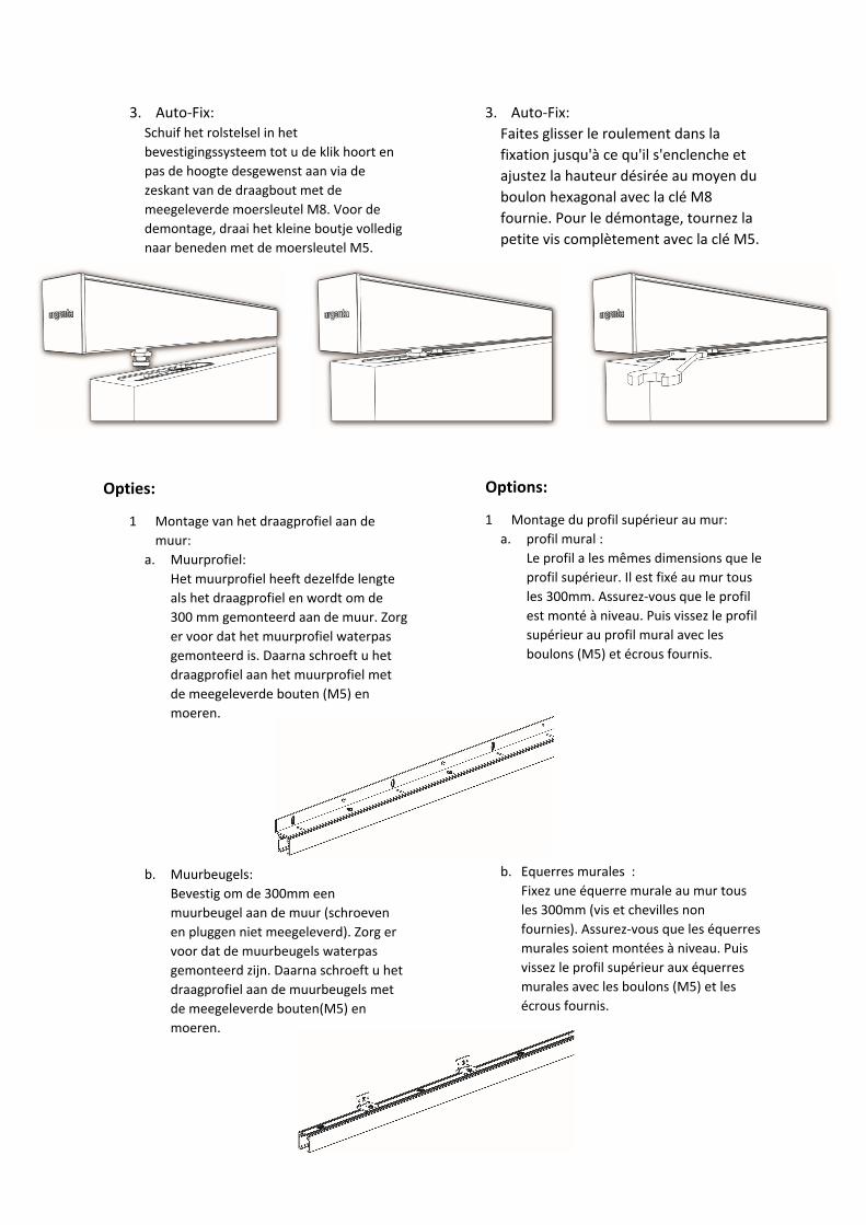
3. Auto-Fix:
Schuif het rolstelsel in het
bevestigingssysteem tot u de klik hoort en
pas de hoogte desgewenst aan via de
zeskant van de draagbout met de
meegeleverde moersleutel M8. Voor de
demontage, draai het kleine boutje volledig
naar beneden met de moersleutel M5.
Opties:
1 Montage van het draagprofiel aan de
muur:
a. Muurprofiel:
Het muurprofiel heeft dezelfde lengte
als het draagprofiel en wordt om de
300 mm gemonteerd aan de muur. Zorg
er voor dat het muurprofiel waterpas
gemonteerd is. Daarna schroeft u het
draagprofiel aan het muurprofiel met
de meegeleverde bouten (M5) en
moeren.
b. Muurbeugels:
Bevestig om de 300mm een
muurbeugel aan de muur (schroeven
en pluggen niet meegeleverd). Zorg er
voor dat de muurbeugels waterpas
gemonteerd zijn. Daarna schroeft u het
draagprofiel aan de muurbeugels met
de meegeleverde bouten(M5) en
moeren.
3. Auto-Fix:
Faites glisser le roulement dans la
fixation jusqu'à ce qu'il s'enclenche et
ajustez la hauteur désirée au moyen du
boulon hexagonal avec la clé M8
fournie. Pour le démontage, tournez la
petite vis complètement avec la clé M5.
Options:
1 Montage du profil supérieur au mur:
a. profil mural :
Le profil a les mêmes dimensions que le
profil supérieur. Il est fixé au mur tous
les 300mm. Assurez-vous que le profil
est monté à niveau. Puis vissez le profil
supérieur au profil mural avec les
boulons (M5) et écrous fournis.
b. Equerres murales :
Fixez une équerre murale au mur tous
les 300mm (vis et chevilles non
fournies). Assurez-vous que les équerres
murales soient montées à niveau. Puis
vissez le profil supérieur aux équerres
murales avec les boulons (M5) et les
écrous fournis.

2 Kunststof eindkappen:
Klik de kunstofeindkappen op het
draagprofiel
3 Montage van het afdekprofiel: Klik het
afdekprofiel op het draagprofiel. Op beide
zijden kan u de alu eindkappen schuiven.
2. Embouts en synthétique pour le profil
supérieur :
Cliquez l’embout sur le profil.
3 Montage du profil cache-rail : Cliquez le
profil cache-rail sur le profil supérieur. Des
deux côtés vous pouvez coulisser les
embouts en aluminium.
User guide for argenta® proslide Montageanleitung argenta® proslide
Read this guide carefully before you start.
The argenta® proslide should be installed by a professional.
Lesen Sie diese Anleitung aufmerksam durch, bevor Sie mit der Montage beginnen.
Die Montage von argenta® proslide muss durch einen Fachmann erfolgen.
Assembly instructions
Step 1: Preparation of the door leaf.
Positioning of the fixation system and bottom
guiding system
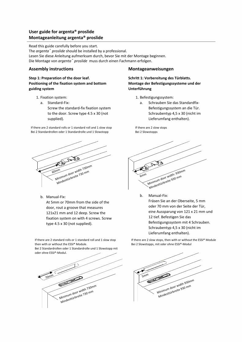
1. Fixation system:
a. Standard-Fix:
Screw the standard-fix fixation system
to the door. Screw type 4.5 x 30 (not
supplied).
b. Manual-Fix:
At 5mm or 70mm from the side of the
door, rout a groove that measures
121x21 mm and 12 deep. Screw the
fixation system on with 4 screws. Screw
type 4.5 x 30 (not supplied).
Montageanweisungen
Schritt 1: Vorbereitung des Türblatts.
Montage der Befestigungssysteme und der
Unterführung
1. Befestigungssystem:
a. Schrauben Sie das Standardfix-
Befestigungssystem an die Tür.
Schraubentyp 4,5 x 30 (nicht im
Lieferumfang enthalten).
b. Manual-Fix:
Fräsen Sie an der Oberseite, 5 mm
oder 70 mm von der Seite der Tür,
eine Aussparung von 121 x 21 mm und
12 tief. Befestigen Sie das
Befestigungssystem mit 4 Schrauben.
Schraubentyp 4,5 x 30 (nicht im
Lieferumfang enthalten).
If there are 2 slow stops
Bei 2 Slowstopps
If there are 2 standard rolls or 1 standard roll and 1 slow stop
Bei 2 Standardrollen oder 1 Standardrolle und 1 Slowstopp
If there are 2 standard rolls or 1 standard roll and 1 slow stop
then with or without the ESSI® Module.
Bei 2 Standardrollen oder 1 Standardrolle und 1 Slowstopp mit
oder ohne ESSI®-Modul.
If there are 2 slow stops, then with or without the ESSI® Module
Bei 2 Slowstopps, mit oder ohne ESSI®-Modul
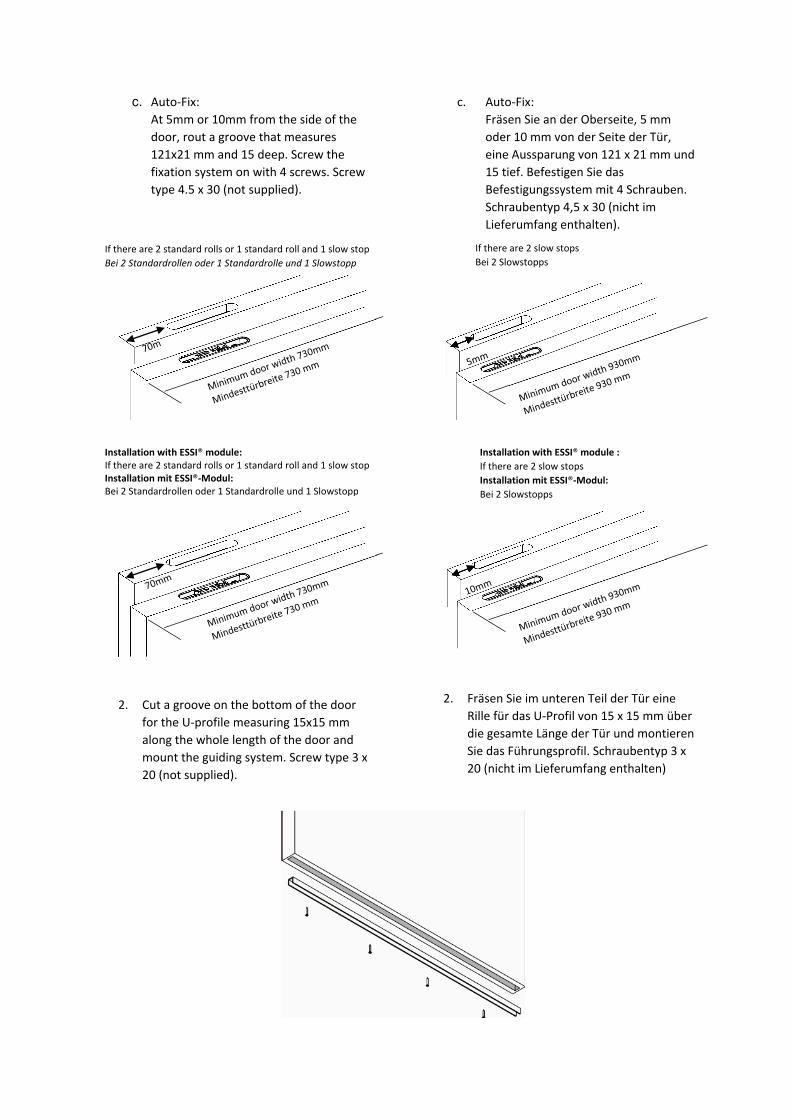
c. Auto-Fix:
At 5mm or 10mm from the side of the
door, rout a groove that measures
121x21 mm and 15 deep. Screw the
fixation system on with 4 screws. Screw
type 4.5 x 30 (not supplied).
2. Cut a groove on the bottom of the door
for the U-profile measuring 15x15 mm
along the whole length of the door and
mount the guiding system. Screw type 3 x
20 (not supplied).
c. Auto-Fix:
Fräsen Sie an der Oberseite, 5 mm
oder 10 mm von der Seite der Tür,
eine Aussparung von 121 x 21 mm und
15 tief. Befestigen Sie das
Befestigungssystem mit 4 Schrauben.
Schraubentyp 4,5 x 30 (nicht im
Lieferumfang enthalten).
2. Fräsen Sie im unteren Teil der Tür eine
Rille für das U-Profil von 15 x 15 mm über
die gesamte Länge der Tür und montieren
Sie das Führungsprofil. Schraubentyp 3 x
20 (nicht im Lieferumfang enthalten)
If there are 2 standard rolls or 1 standard roll and 1 slow stop
Bei 2 Standardrollen oder 1 Standardrolle und 1 Slowstopp
If there are 2 slow stops
Bei 2 Slowstopps
Installation with ESSI® module: If there are 2 standard rolls or 1 standard roll and 1 slow stop
Installation mit ESSI®-Modul: Bei 2 Standardrollen oder 1 Standardrolle und 1 Slowstopp
Installation with ESSI® module :
If there are 2 slow stops
Installation mit ESSI®-Modul: Bei 2 Slowstopps
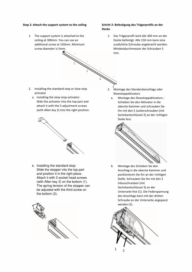
Step 2: Attach the support system to the ceiling
1. The support system is attached to the
ceiling at 300mm. You can use an
additional screw at 150mm. Minimum
screw diameter is 5mm.
2. Installing the standard stop or slow stop
activator
a. Installing the slow stop activator:
Slide the activator into the top part and
attach it with the 5 adjustment screws
(with Allen key 2) into the right position.
b. Installing the standard stop:
Slide the stopper into the top part
and position it in the right place.
Attach it with 2 socket head screws
(with Allen key 3) on the bottom (1).
The spring tension of the stopper can
be adjusted with the third screw on
the bottom (2).
Schritt 2: Befestigung des Trägerprofils an der
Decke
1. Das Trägerprofil wird alle 300 mm an der
Decke befestigt. Alle 150 mm kann eine
zusätzliche Schraube angebracht werden.
Mindestdurchmesser der Schrauben 5
mm.
2. Montage des Standardanschlags oder
Slowstoppaktivators
a. Montage des Slowstoppaktivators::
Schieben Sie den Aktivator in die
oberste Kammer und schrauben Sie
ihn mit den 5 Justierschrauben (mit
Sechskantschlüssel 2) an der richtigen
Stelle fest.
b. Montage des Schieben Sie den
Anschlag in die oberste Kammer und
positionieren Sie ihn an der richtigen
Stelle. Schrauben Sie ihn mit den 2
Inbusschrauben (mit
Sechskantschlüssel 3) an der
Unterseite fest (1). Die Federspannung
des Anschlags kann mit der dritten
Schraube an der Unterseite angepasst
werden (2).
1 2
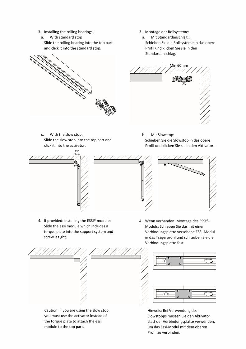
3. Installing the rolling bearings:
a. With standard stop
Slide the rolling bearing into the top part
and click it into the standard stop.
c. With the slow stop:
Slide the slow stop into the top part and
click it into the activator.
4. If provided: Installing the ESSI® module:
Slide the essi module which includes a
torque plate into the support system and
screw it tight.
3. Montage der Rollsysteme:
a. Mit Standardanschlag::
Schieben Sie die Rollsysteme in das obere
Profil und klicken Sie sie in den
Standardanschlag.
b. Mit Slowstop:
Schieben Sie die Slowstop in das obere
Profil und klicken Sie sie in den Aktivator.
4. Wenn vorhanden: Montage des ESSI®-
Moduls: Schieben Sie das mit einer
Verbindungsplatte versehene ESSI-Modul
in das Trägerprofil und schrauben Sie die
Verbindungsplatte fest
é
Min
60mm
Min 60mm
Caution: if you are using the slow stop,
you must use the activator instead of
the torque plate to attach the essi
module to the top part.
Hinweis: Bei Verwendung des
Slowstopps müssen Sie den Aktivator
statt der Verbindungsplatte verwenden,
um das Essi-Modul mit dem oberen
Profil zu verbinden.

Step 3: Position the bottom guiding rail perfectly
vertically under the support system, on the floor.
Screw type 4.5 x 30 (not supplied)
Step 4: Hanging the door
1. Standard-Fix:
a. Hook the fixation systems to the rolling
bearings.
b. If needed, adjust the height of the door
by turning the bolt head
c. Tighten the nut with the supplied
wrench. Block it with a 2nd M8
wrench.
2. Manual-Fix:
Hang the fixation system to the rolling
bearings, slide the cover shut and tighten
the bolt with the supplied M5 wrench.
Adjust the height, if necessary, by using the
hexagon of the support bolt.
Schritt 3: Montieren Sie die untere Führung
perfekt senkrecht unter das Trägerprofil auf den
Fußboden. Schraubentyp 4,5 x 30 (nicht im
Lieferumfang enthalten)
Schritt 4 Einhängen der Tür
1. Standard-Fix:
a. Haken Sie die Befestigungssysteme in
die Rollsysteme.
b. Passen Sie eventuell die Höhe an, indem
Sie den Schraubenkopf drehen c. Ziehen Sie die Mutter mit dem
mitgelieferten Schlüssel fest. Blockieren
Sie mit einem 2. Schraubenschlüssel M8.
2. Manual-Fix:
Hängen Sie das Befestigungssystem an das
Rollsystem. Schieben Sie die Klappe zu und
schrauben Sie die Schraube mit dem
mitgelieferten Schraubenschlüssel M5 fest.
Passen Sie eventuell die Höhe über das
Sechskant der Trägerschraube an.
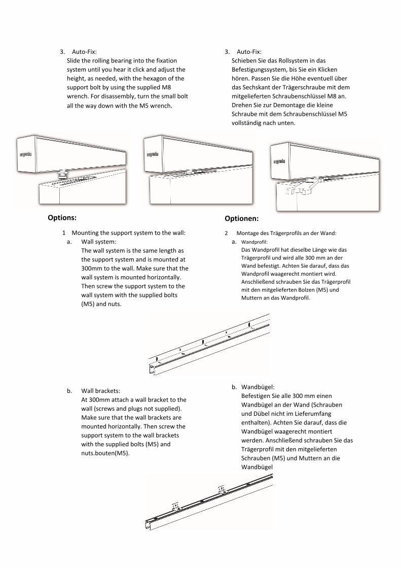
3. Auto-Fix:
Slide the rolling bearing into the fixation
system until you hear it click and adjust the
height, as needed, with the hexagon of the
support bolt by using the supplied M8
wrench. For disassembly, turn the small bolt
all the way down with the M5 wrench.
Options:
1 Mounting the support system to the wall:
a. Wall system:
The wall system is the same length as
the support system and is mounted at
300mm to the wall. Make sure that the
wall system is mounted horizontally.
Then screw the support system to the
wall system with the supplied bolts
(M5) and nuts.
b. Wall brackets:
At 300mm attach a wall bracket to the
wall (screws and plugs not supplied).
Make sure that the wall brackets are
mounted horizontally. Then screw the
support system to the wall brackets
with the supplied bolts (M5) and
nuts.bouten(M5).
3. Auto-Fix:
Schieben Sie das Rollsystem in das
Befestigungssystem, bis Sie ein Klicken
hören. Passen Sie die Höhe eventuell über
das Sechskant der Trägerschraube mit dem
mitgelieferten Schraubenschlüssel M8 an.
Drehen Sie zur Demontage die kleine
Schraube mit dem Schraubenschlüssel M5
vollständig nach unten.
Optionen:
2 Montage des Trägerprofils an der Wand:
a. Wandprofil:
Das Wandprofil hat dieselbe Länge wie das
Trägerprofil und wird alle 300 mm an der
Wand befestigt. Achten Sie darauf, dass das
Wandprofil waagerecht montiert wird.
Anschließend schrauben Sie das Trägerprofil
mit den mitgelieferten Bolzen (M5) und
Muttern an das Wandprofil.
Manual
b. Wandbügel:
Befestigen Sie alle 300 mm einen
Wandbügel an der Wand (Schrauben
und Dübel nicht im Lieferumfang
enthalten). Achten Sie darauf, dass die
Wandbügel waagerecht montiert
werden. Anschließend schrauben Sie das
Trägerprofil mit den mitgelieferten
Schrauben (M5) und Muttern an die
Wandbügel
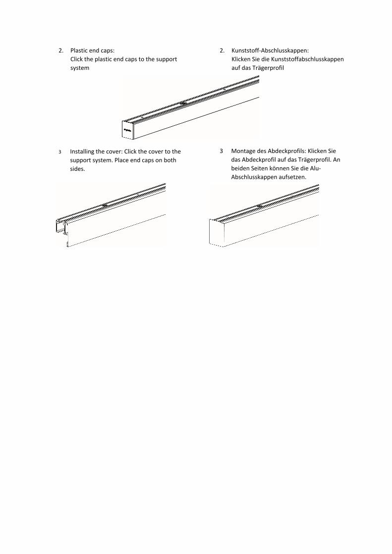
2. Plastic end caps:
Click the plastic end caps to the support
system
3 Installing the cover: Click the cover to the
support system. Place end caps on both
sides.
2. Kunststoff-Abschlusskappen:
Klicken Sie die Kunststoffabschlusskappen
auf das Trägerprofil
3 Montage des Abdeckprofils: Klicken Sie
das Abdeckprofil auf das Trägerprofil. An
beiden Seiten können Sie die Alu-
Abschlusskappen aufsetzen.
Recommended