�
DDPP3300 -- DDPP3300KK --DDPP4422 -- DDPP4422 KK HH��DDRROOLL��KK DDÜÜMMEENN EELL PPOOMMPPAASSII MMOONNTTAAJJ VVEE KKUULLLLAANNIIMM KKIILLAAVVUUZZUU
DDPP3300 -- DDPP3300KK ––DDPP4422 -- DDPP4422 KK HHYYDDRRAAUULLIICC SSTTEEEERRIINNGG HHEELLMM PPUUMMPP IINNSSTTAALLLLEERR’’SS AANNDD OOWWNNEERR’’SSMMAANNUUAALL
ISO 10592: 2000

DATA hidrolik dümen el pompası talimatlara uygun kullanım ve düzenli bakım �artları ile uzun süre problemsiz hizmet vermek amacıyla dizayn edilmi�tir. Bu kitapçık hidrolik dümen el pompası ve komple dümen sistemi ile ilgili kullanım ve düzenli bakım talimatlarını içermektedir. Bu kitapçı�ı lütfen saklayınız, kullanım ve yedek parça ile ilgili tüm taleplerinizde lütfen bu kitapçıkta belirtilen pompa tipini ve seri no.’sunu belirtiniz.
The DATA hydraulic steering helm pump is designed to give long consistent trouble free service, but this service is dependent of the proper operation, care and regular maintenance of the equipment. The manual give detailed instructions and information relevant to the carrying out of these procedures. The instructions should be carefully followed to ensure that this trouble free service is achieved in practice. Please keep this manuel and in all communication relating to service and spares, please quote the type of the helm pump and the serial number stated in this manual.
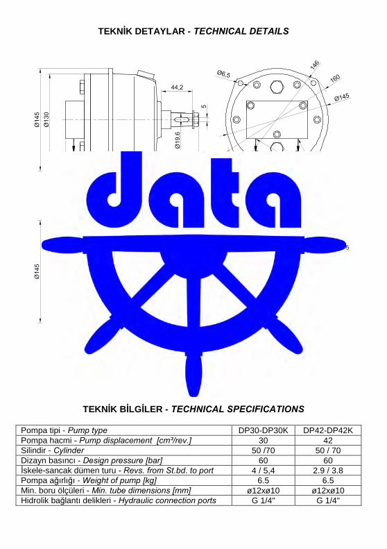
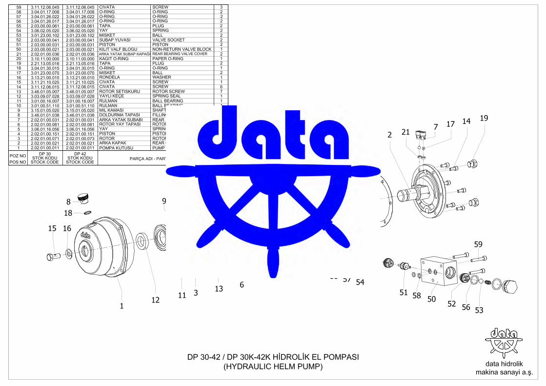
TEKN�K DETAYLAR - TECHNICAL DETAILS
�ekil 1 (Drw 1)
TEKN�K B�LG�LER - TECHNICAL SPECIFICATIONS Pompa tipi - Pump type DP30-DP30K DP42-DP42K Pompa hacmi - Pump displacement [cm³/rev.] 30 42 Silindir - Cylinder 50 /70 50 / 70 Dizayn basıncı - Design pressure [bar] 60 60 �skele-sancak dümen turu - Revs. from St.bd. to port 4 / 5,4 2.9 / 3.8 Pompa a�ırlı�ı - Weight of pump [kg] 6.5 6.5 Min. boru ölçüleri - Min. tube dimensions [mm] ø12xø10 ø12xø10 Hidrolik ba�lantı delikleri - Hydraulic connection ports G 1/4" G 1/4"
H�DROL�K DÜMEN EL POMPASI MONTAJ VE KULLANIM KILAVUZU
1- Pompa montajı : 1.1- Tek merkezli kumanda 1.1.1- Pompa yatayla en fazla 20° açı yapacak �ekilde monte edilmelidir. (�ekil 2) 1.1.2- Kumanda yerinde daha önce hazırlanan panele pompayı dört adet cıvata ile ba�layınız. Panel sa�lam olmalı ve
dümen simidi zorlandı�ı zaman oynamamalıdır. 1.1.3- Pompanın alt yanlarındaki basınç çıkı�larını silindirden gelen devrelere irtibatlayın. 1.2- Çift merkezli kumanda 1.2.1- Çift merkezli sistemlerde, pompaları yukarıda tek merkezlide oldu�u gibi panellere ba�layın. 1.2.2- Hidrolik ba�lantı �emasında (�ekil 4) görüldü�ü gibi pompaların çıkı�larını T fittingler ile birle�tirin. Daha sonra
silindirden gelen devrelere irtibatlayın. DP 30 ve DP 42 pompalar kendi üzerinde kilit valf ile donatıldı�ından devreye ayrıca kilit valf konmasına gerek yoktur.
1.2.3- Tesisat boru boylarının fazla uzun olmaması bakımından, T fittingin alttaki pompaya yakın bir konumda monte edilmesi faydalı olur.
1.2.4- Çift merkezli sistemlerde, alt pompanın üstünden, üst pompanın altına bir ya� dengeleme hattı (�ekil 4 No.8) çekilmelidir. Bu yapılmadı�ı taktirde sistemin havası tam olarak alınamaz ve alt pompada a�ırı basınçtan ya� kaçakları olu�ur.
1.2.5- Çift merkezli kumandada alttaki pompada deliksiz ya� doldurma tapası, üst pompada ise delikli ya� doldurma tapası takılı olmalıdır.
1.2.6- Montaj sırasında temizli�e azami derecede dikkat edin ve kullanaca�ınız boruların içini montajdan önce mutlaka temizleyin.
1.2.7- Hidrolik tesisat boruları kesinlikle kelepçelerle desteklenmeli ve vibrasyon etkilerine kar�ı korunmalıdırlar. 2- Pompa montajı do�rulu�unun kontrolü : • Pompadan silindire çekilecek tesisatta hava sıkı�masına sebep olabilecek ini� ve çıkı�lar olmamalıdır. Tesisat
yukarıdan a�a�ıya devamlı ini� olacak �ekilde düzenlenmelidir. • Hidrolik tesisat tamamlanıp sistemin ya�ı doldurulduktan sonra, dümen simidini çevirerek yekenin do�ru tarafa
dönüp dönmedi�ini kontrol edin. E�er yanlı�sa, pompa veya silindir üzerinden hortumların yerlerini de�i�tirin. 3- Sistemin kullanımı :
DATA hidrolik dümen sistemi, bir pompa, bir silindir ve bir kilit valften meydana gelmektedir. Hidrolik dümen sisteminin kullanımı çok basittir. Pompaya ba�lı dümen simidinin çevrilmesi ile hidrolik güç elde edilir. Pompa silindirin dönme yönüne göre silindirin iskele veya sancak tarafına ya� basar ve yekenin iskele veya sancak yönünde dönmesini sa�lar. Pompa ile silindir arasına konulan kilit valf dümen yelpazesini hidrolik olarak kilitler ve dümeni, simit döndürülmedi�i sürece her türlü �artta sabit tutar. Dümen sistemi do�ru monte edilip havası alındıktan sonra kullanım esnasında ba�ka hiçbir müdahaleye gerek olmaksızın dümen simidi sancak veya iskele yönünde çevrilerek sistem kumanda edilir.
4- Sisteme ya� doldurma : Tek merkezli kumanda Sistemin ya�ı, pompa üzerinde bulunan ya� doldurma tapası açılarak doldurulur. Ya� doldurma i�lemi sırasında, ya�ın tesisata ve silindire gitmesi için, dümen simidini a�ır a�ır bir yöne, sonra di�er yöne çevirerek sistemin havasını alın. Her iki yöne çevrildi�inde, pompanın içindeki ya� seviyesi dü�meyene kadar bu i�leme devam edin. Çift merkezli kumanda Montajdan sonra alt seviyede bulunan pompayı yukarıda tarif edildi�i gibi ya� ile doldurun. Bu pompa dolduktan sonra üst tapasını sıkıca kapatın ve üst seviyede bulunan pompadan sisteme ya� doldurun ve tekrar sistemin havasını alın. Daha sonra kullanma sırasında ya� eksikli�ini sadece üst pompadan tamamlayın. Alt pompanın ya� doldurma tapası hiç açılmamalıdır.
5- Sistemin havasının alınması : 5.1- Dümen simidini a�ır a�ır bir yöne çevirin. Bu çevirme sırasında bir müddet sonra piston milinin kesik kesik
ilerledi�ini göreceksiniz. 5.2- Piston milinin ileri hareketinde, arka ba�lıkta bulunan pürjörü bir anahtar (AA 8 mm) vasıtasıyla hafifçe gev�etin.
Pürjörden önce hava, daha sonra ya�la karı�ık hava çıkacaktır. Havasız ya� akmaya ba�ladı�ı zaman pürjörü sıkın.
5.3- Dümen simidini aksi yönde çevirmeye ba�layın. Bu sefer piston mili geri hareket edecektir. Ön ba�lıkta bulunan pürjörden havayı alın.
5.4- �leri geri hava alma i�lemini 8-10 sefer tekrarlayın. Her seferinde havanın daha az çıktı�ını göreceksiniz. Hava alma sırasında pompadaki ya� seviyesini kontrol edin ve tamamlayın.
5.5- Çift merkezden kumandalı sistemlerde alt pompanın ya� doldurma tapası herzaman kapalı olmalı ve hava alma esnasında ya� seviyesi üst pompadan kontrol edilmelidir.
5.6- Sistemdeki havanın tam olarak çıkması 3-4 gün sürebilir. Bu nedenle aynı i�lemleri hava tam olarak çıkana kadar 3-4 gün ara ile tekrar etmeniz tavsiye edilir.
6- Arıza durumunda alternatif kullanım yolları : Hidrolik dümen sistemini olu�turan ünitelerden bir veya birkaçında herhangi bir sebeple meydana gelebilecek bir arıza neticesinde sistem kullanılamaz duruma gelirse alternatif �ekli dümenin el yekesi ile kullanılmasıdır
Bunun için dümen milinin üst kısmı el yekesi ba�lanacak �ekilde yapılmalıdır. Sistemin montajı esnasında silindir giri� ve çıkı�larını i�tirakleyen bir by-pass vanasının sisteme monte edilmesi tavsiye edilir. Bu durumda bir arıza halinde by-pass vanası açılarak dümen el yekesi ile kumanda edilebilir. Bu vana olmadı�ı taktirde dümenin el yekesi ile kumanda edilebilmesi için yeke piminin çıkarılması ve silindir ile yekenin birbirinden ayrılması gerekmektedir.
7- Sistemin bakımı : DATA hidrolik dümen sisteminin uzun süre problemsiz hizmet vermesini sa�lamak için a�a�ıdaki kontrolleri periyodik olarak yapın;
• Pompadaki ya� seviyesini kontrol edin, eksik ise tamamlayın ve devereyi kaçak ihtimaline kar�ı kontrol edin. • Dümen silindirinin çalı�masına herhangi bir�eyin engel olmadı�ını kontrol edin. • Silindiri tekneye ba�layan silindir tespit civatalarını mil somununu gev�eme ihtimaline kar�ı kontrol edin. • Ekipmanların bazı kısımları korozyona kar�ı boya ile korunmaktadır. Herhangi bir sebeple boyasında bir bozulma
durumunda korozyon etkilerine kar�ı boyasını tamir edin. 8- Kar�ıla�ılabilecek sorunlar ve dikkat edilmesi gereken hususlar: • Sorun : Ya� kaça�ı
Tüm devreyi, ba�lantı ve fittingleri kontrol edin ve gev�ek olan varsa sıkın, hasarlı olan varsa mümkün olan en kısa sürede yenileyin.
• Sorun : Dümen simidinin kesikli dönmesi, Sistemde hava vardır, yukarıda tarif edildi�i �ekilde sistemin havasını alın.
• Sorun : Dümen simidinin zor ve sesli dönmesi, Tesisat belirtilenden daha dar çekilmi� veya tesisatın bazı kısımlarında dar kesit veya kesitler bulunmaktadır, tesisatın daha geni� çaplı çekilmesi gerekir. Dümen mili bir dı� etken sebebiyle sıkı�ık olabilir. Yeke pimini çıkarınız ve silindiri yekeden ayırıp yeke vasıtasıyla dümen milini çevirerek sıkı�ık olup olmadı�ını kontrol edin. UYARILAR!
• Nakliye, montaj, depolama sırasında piston milinin ve silindir borusunun zedelenmemesine özellikle dikkat edin. • Verilen yeke boylarına göre dümeniniz 35° iskele, 35° sancak dönecektir. Yekenin tam alabanda durumunda
de�ece�i stoperler kuıllanılmalıdır. Tam alabanda durumunda dümeni daha fazla döndürmek için zorlamayın. • Teknede yeteri kadar yedek dümen hidrolik ya�ı bulundurun. • Yukarıda belirtilenler dı�ında herhangi bir arıza durumunda pompa veya silindirin içini sökmeye veya açmaya
çalı�madan aldı�ınız satıcımıza, en yakın servisimize veya direkt olarak firmamıza ba�vurun. 9- Hidrolik akı�kan :
Hidrolik dümen sisteminde birinci sınıf, paslanma, a�ınma, oksitlenme ve köpürmeye kar�ı katkılar içeren mineral ya� kullanılmalıdır. Ya� a�a�ıdaki özelliklere uygun olmalıdır;
• Akma noktası minimum çevre ısısının üzerinde olmalı, • Alevlenme noktası minimum 157°C olmalı, • Ya�ın viskozitesi 40°C de 22-32 cSt arasında olmalı,
Tavsiye edilen ya�lar: • BP Energol HLP HM22 - BP Energol HLP HM32 • CASTROL Hyspin AWS 22 - Hyspin AWS 32 • MOBIL DTE 22 – DTE 24 • PETROL OF�S� Oil HD 22 - Oil HD 32 • SHELL Tellus 22 - Tellus 32
Yukarıdaki liste ya�ın kalitesine göre de�il, alfabetik sıraya göre sıralanmı�tır ve kullanılabilir bütün ya�ları kapsamamaktadır.
10- Sistemin temizli�i : Hidrolik sistemlerde en önemli husus temizliktir. Kullanaca�ınız ya�ı mutlaka süzerek kullanın. Tesisat borularının içinde kir , pas, çapak bulunmamalıdır. Temizlik için üstüpü kullanmayın, bez kullanın. En ufak bir pislik parçası sistemi kullanılmaz hale getirebilir.
11- Ba�lantılarda sızdırmazlık için alınması tavsiye edilen tedbirler : • Ba�lantılarda yeni ve kullanılmamı� fitting elemanları tercih edilmelidir. • Fitting elemanları ile birlikte yeni bakır pul veya tercihen kendinden lastik contalı ba�lantı elemanı kullanılmalıdır. • Sızdırmazlık için ayrıca bir sızdırmazlık sıvısı kullanılması tavsiye edilir. 12- Tavsiye edilen esnek hortum ve boru özellikleri :
Silindir çıkı�ında esnek hortum olarak SAE 100 R1 kalite ve tesisatta kullanılacak çelik çekme boru ölçüsüne uygun ölçüde hortum kullanın. Dümen tipine göre kullanılması tavsiye edilen çelik çekme boru ölçüsü “TEKN�K B�LG�LER” ba�lı�ı altındaki tabloda belirtilmektedir.
HYDRAULIC HELM PUMP INSTALLATION AND OPERATING INSTRUCTIONS 1- Helm pump assembly : 1.1- Single steering station 1.1.1- The pump should be mounted on the panel with an angle of max 20° with horizontal. (Drw. 2) 1.1.2- Fix the pump onto the panel prepared in the control station by means of four bolts. The panel should be firm and it
should not move when you force on the steering wheel. 1.1.3- Connect the pressure outlets of the pump to the two hydraulic lines connected to the cylinder. 1.2- Dual steering station 1.2.1- In dual steering systems, bolt the pump onto the panels as described above. 1.2.2- As seen in the drw.3, connect the outlets of the pumps with T fittings. Than connect to the lines coming from the
cylinder. The DP30 and DP 42 model pumps are equipped with non-return valve and an additional non-retun valve is not required to be fitted on the hydraulic lines.
1.2.3- It is advantageous for the T fitting to be fixed close to the lower pump as the installation pipes will not be very long. 1.2.4- In dual systems an oil balancing line (Drw.4 No.8) should be set between the top of the lower pump and the bottom
of the pump at the top. If that is not done you can not let the air out of the system completely and oil leakages will appear in the lower pump due to high pressure.
1.2.5- In dual steering systems the lower pump should be fitted with a fillercap without air purge and the upper pump should be fitted with a fillercap with air purge.
1.2.6- Hydraulic lines should be supported by clips, straps or other means to prevent chafing or vibration damage. 1.2.7- During the assembly take utmost care as regards cleanliness and clean the insides of the pipes you will use before
assembly. 2- Check of correct helm pump assembly .
The connection from the pump to the cylinder should not have ups and downs that might cause air trapp. It should be installed to form a descend only. After the installation of the system is compleated and the oil is filled, by rotating the steering wheel check whether the tiller is moving in the correct direction or not. If it is wrong replace the places of the hoses either on the cylinder or on the pump.
3- Operating the hydraulic steering system : The DATA hydraulic steering system consists of a cylinder, a helm pump and a non-return valve. The operation of the steering system is very simple. Hydraulic power is created by rotation of the steering wheel mounted on the helm pump. Pump sens oil to the cylinder one way or the other depending on the direction of rotation of the steering wheel. The hydarulic system is blocked by the non-return valve and will not modify its position in spite of the the various bumps due to rough see conditions, until the steering wheel is activated. This permits a much easier manouvering. After the hydraulic steering system is installed correctly and the air is bleeded, the system is operated by rotating the steering wheel in either direction witout any extra intervention.
4- Oil filling : Single steering station When the assembly is over, open the filler cap on the pump and pour in oil here. To let the oil into the system and to let the air out of the system during filling, turn the steering wheel slowly in one direction, than the other. Continue with this until the level in the pump stops dropping when the wheel is being turned both ways. Dual steering station After the assembly fill the lower pump with oil and let the air out of the system as described above. When this pump has been filled, close the cap on top tightly and fill oil into the system through the pump at the top and let the air out of the system again like described above. Never open the cap of the lower one. In case of adding oil, only fill from the upper pump.
5- Air bleeding of the system : 5.1- Turn the steering wheel slowly in one direction. During this (a short while later) you will observe the piston rod
advancing intermittently. 5.2- As the piston rod moves forward loosen by a wrench (8 mm) the air-purge on the rear cover slightly. Out of the air-
purge will come air first, than air mixed with oil. Tighten the air-purge when oil alone starts coming out. 5.3- Turn the wheel in the opposite direction. This time the piston rod will move backwards. Bleed the air through the air
air-purge on the front cover. 5.4- Repeat this forward-backward air bleeding procedure 8-10 times. You will notice that each time less air will be
discharged. During air bleeding check the pump oil level and add as much as is required. 5.5- While air bleeding in dual systems the fillercap of the lower pump should be tighten. Check the oil level always on
the upper pump. 5.6- The air in the system is able to be discharged from the system completely in 3-4 days. So it is advised to repeat
the procedure after 3-4 days intervals.
6- Alternative means of operation in case of failure : As a result of a failure on any part of the hydraulic steering system by any reason, if the hydraulic steering system comes out of service, the alternative way of operating the rudder is a hand-tiller. However inorder to apply this, it is recommended that the top of the rudder shaft is machined to fit the hand-tiller and a by-pass valve is mounted connecting both sides of the cylinder (Drw.3). Doing so, in case of a failure after opening this valve the rudder can be activated by a hand-tiller. If the system is not fitted with a by-pass valve, in order to operate the rudder by means of a hand-tiller, the cross pin should be removed from its place to disconnect the tiller and piston rod.
7- Maintenance In order obtain a long consistent trouble free service from your DATA hydraulic steering system please apply the following maintenance procedures periodically;
• Check the oil level in the pump, if its low, add oil and check the system agaist the possibility of oil leakage in any part.
• Check agaist the possibilty of something preventing the movement of the piston rod. • Check the bolts mounting the cylinder to the boat agaist the possibilty of loosening. • Some parts of the equipments are proteceted agaist corrosion by paint. If there is any damage on the painted parts
repair it. 8- Trouble shooting and warnings : • Problem : Oil leakage
Chech the complete hydraulic line including fittings and the components, if there is a loose part, tighten, if there is a damaged part, replace it with the new one as soon as possible.
• Problem : Turning of the steering wheel intermittently. There is air in the system, bleed the air as described above.
• Problem : Turning of the steering wheel hardly and noisy. - The hydraulic line might be narrower than it is recommended or there are narrow sections on some part or parts of the line. The hydraulic line should be replaced with larger sections. - The piston rod might be tight due to an external reason. Remove the cross pin from the tiller and try to rotate the rudder shaft by means of tiller and check if it is thighter than it should be. WARNINGS!
• Take special care that the piston rod and cylinder pipe are not damaged during transportation, assembly and storage.
• According to the specified tiller lengths your rudder will turn 35° port and starboard. Stoppers should be placed for the tiller at port and starboard position. Do not strain the pump for extra steerage.
• Keep always plenty of spare hydraulic oil on board. • In case of any malfunctioning or breakdown other than stated above, apply your supplier, closest service or directly
to us. 9- Hydraulic fluid :
The hydarulic steering gear system should be charged with first class mineral lubricating oil containing anti-oxidant, anti-rust, anti-wear and anti-foam additives formulated for use in hydraulic systems.The oil should meet the following specifications:
• Pour point not above minimum ambient temperature • Closed flash point not less than 157°C • Reedwood Viscosity 40°-22-32 cSt
Oil recommendations : • BP Energol HLP HM22 - BP Energol HLP HM32 • CASTROL Hyspin AWS 22 - Hyspin AWS 32 • MOBIL DTE 22 – DTE 24 • PETROL OF�S� Oil HD 22 - Oil HD 32 • SHELL Tellus 22 - Tellus 32
The above list is in alphabetical order and is not indicative of relative quality, nor does it cover all suitable oils. 10- System cleaning :
The point of greatest importance in hydarulic systems is cleanliness. You must filter the oil before use. The installation pipes should be absolutely devoid of dirt, oxidation and grits. Use only cotton for cleaning. The slightest bit of dirt might block the valves and put the steering gear out of use.
11- Thread sealant recommentations : • New and unused fitting elements should be used in the connections. • New and unused copper washers should be used with fittings. It is recommended to use self sealed fittings for best
results. • In the connections it is recommended to use sealant liquid. 12- Recommended pipe and flexible hose specifications :
The flexible hose should be SAE 100 R1 quality and in appropriate size to fit the pipe specified in this manuel for the relevant type of cylinder. The dimensions of pipes recommended according to the cylinder type can be found under table “TECHNICAL SPECIFICATIONS”.
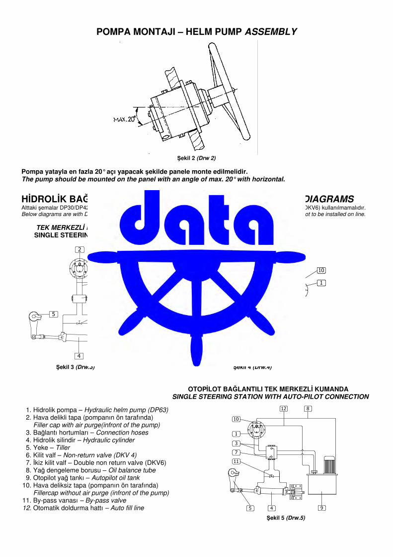
POMPA MONTAJI – HELM PUMP ASSEMBLY
�ekil 2 (Drw 2)
Pompa yatayla en fazla 20° açı yapacak �ekilde panele monte edilmelidir. The pump should be mounted on the panel with an angle of max. 20° with horizontal.
H�DROL�K BA�LANTI �EMALARI – HYDRAULIC CONNECTION DIAGRAMS Alttaki �emalar DP30/DP42 ile yapılmı�tır. DP30K veya DP42K kullanıldı�ında devredeki kilit valf (DKV4, DKV4B, DKV6) kullanılmamalıdır. Below diagrams are with DP30/DP42. When using with DP30K/DP42K, Non-return valve (DKV4, DKV4B, DKV6) not to be installed on line.
TEK MERKEZL� KUMANDA �FT MERKEZL� KUMANDA SINGLE STEERING STATION DUAL STEERING STATION
�ekil 3 (Drw.3) �ekil 4 (Drw.4)
OTOP�LOT BA�LANTILI TEK MERKEZL� KUMANDA SINGLE STEERING STATION WITH AUTO-PILOT CONNECTION
�ekil 5 (Drw.5)
1. Hidro lik po mpa – H y draulic helm p ump (DP63) 2. Hava delikli tapa (po mpanın ö n tarafında) Filler c ap with air p urge(infront of the p ump ) 3. Ba�lantı h o rtumları – C onnec tion hoses 4. Hidro lik s ilindir – H y draulic c y linder 5. Yeke – T iller 6. Kilit valf – Non-return valve (DKV 4) 7. �kiz kilit valf – Do ub le no n return valve (DKV6) 8. Ya� deng eleme b o rus u – O il balanc e tube 9. Oto pilo t ya� tankı – A utop ilot oil tank 10. Hava deliks iz tapa (po mpanın ö n tarafında) Fillerc ap without air p urge (infront of the p ump ) 11. By-pas s vanas ı – By -p ass valve 1 2. Oto matik do ldurma h attı – A uto fill line
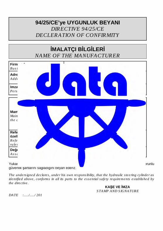
94/25/CE’ye UYGUNLUK BEYANI DIRECTIVE 94/25/CE
DECLERATION OF CONFIRMITY
�MALATÇI B�LG�LER� NAME OF THE MANUFACTURER
Firma adı Business name
Data Hidrolik Makina Sanayi A.�.
Adres Address
�stanbul Deri Organize Sanayi Bölgesi, Yan Sanayi Alanı YA-8 Parsel Aynlı-Tuzla 34953 �STANBUL - TÜRK�YE
Imzalamaya yetkili �ahıs Person empowered to sign
Mamulün temel özellikleri Main characteristics of the component
�sim / Name : Hydraulic Helm Pump
Model / Model : DP.........
Hacim / Volume : ......... cm³/rev.
Dizayn basıncı : 60 bar Design Press.
Referans alınan kurallar / özellikler References to the rules / specifications
�lgili kurallar listesi : 5.4 Steering System List of harmonised rules ISO 10592
De�erlendirme modülü Assessment module
B + C
Yukarıda tanımlanan hidrolik dümen silindirinin tüm parçaları ile direktifte belirtilen zorunlu güvenlik �artlarını sa�ladı�ını beyan ederiz. The undersigned declares, under his own responsibility, that the hydraulic steering cylinder as identified above, conforms in all its parts to the essential safety requirements established by the directive. KA�E VE �MZA
STAMP AND SIGNATURE DATE :...../...../ 201
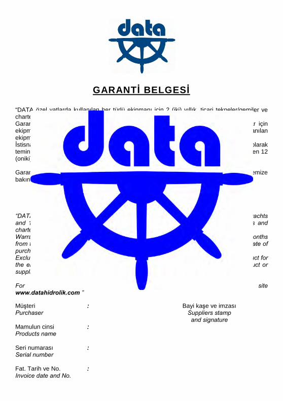
GARANT� BELGES� “DATA özel yatlarda kullanılan her türlü ekipmanı için 2 (iki) yıllık, ticari tekneler/gemiler ve charter yatlarda kullanılan her türlü ekipmanı için 1 (bir) yıllık garanti sa�lamaktadır. Garanti, gemi/tekne/yat teslimi itibariyle ba�lar ve özel yatlarda kullanılan ekipmanlar için ekipmanın satın alınmasından itibaren 30 (otuz) ay, ticari gemi ve charter yatlarda kullanılan ekipmanlar için ekipmanın satın alınmasından itibaren 18 (onsekiz) ayı a�amaz. �stisnai durumlar: Bu garanti DATA ürünü üzerinde ba�lı veya DATA ürününün parçası olarak temin edilmi� elektrik, elektronik ve hidrolik ekipmanlar için satın alınma tarihinden itibaren 12 (oniki) ay geçerlidir. Garanti �artlarının detayları ve sınırlamalar için www.datahidrolik.com internet sitemize bakınız.”
STATEMENT OF WARRANTY
“DATA provides 2 (two) year limited warranty for all its equipments used on pleasure yachts and 1 (one) year limited warranty for all its equipments used on commercial vessels and charter yachts. Warranty starts from the delivery of the vessel, which cannot be longer than 30 (thirty) months from the date of purchase for the pleasure yachts and 18 (eighteen) months from the date of purchase for the commercial vessels and charter yachts. Exclusion: This warranty is limited to 12 (twelve) months from the purchase of the product for the electric, electronic and hydraulic equipments which are installed on a DATA product or supplied as a part of DATA product. For details of warranty terms and limitations please refer to our web site www.datahidrolik.com ” Mü�teri : Bayi ka�e ve imzası Purchaser Suppliers stamp
and signature Mamulun cinsi : Products name Seri numarası : Serial number Fat. Tarih ve No. : Invoice date and No.
������������������ �����������
�stanbul Deri Organize Sanayi Bölgesi Yan Sanayi Alanı YA-8 Parsel Aydınlı, Tuzla - �stanbul Tel : +90.216.591.07.45 – 46 – 47 – 48 Fax : +90.216.591.02.51
E-mail : [email protected] web : www.datahidrolik.com
Recommended