Introduction and Overview
• Why Hydro• History• Possibilities / Opportunities / Potential• Problems / Pitfalls / Regulation• Who I am
1
Why Hydro?
• Most common renewable energy • Well developed technology• Most efficient means of producing
electricity• Multiple uses of water resource
2
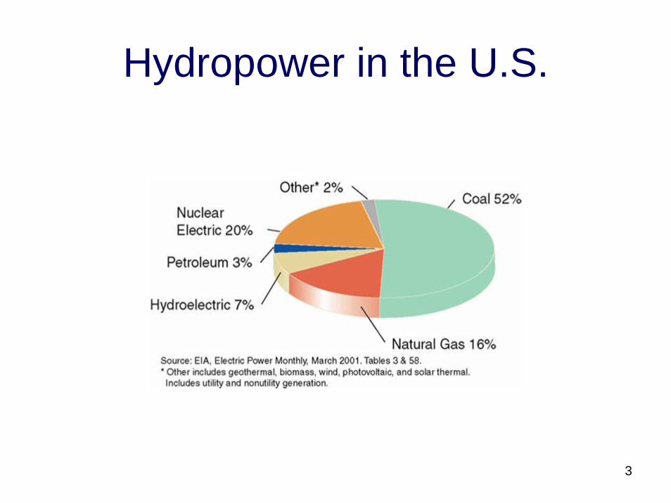
Hydropower in the U.S.
3
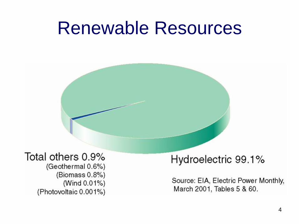
Renewable Resources
4
History
• From Edison decentralized DC powerhouses to Tesla AC
• Larger scale power• Unreliable grid• Availability of smaller scale
turbines/generators
5
Possibilities / Potentials / Opportunities
• Significant water resources everywhere, of which only 20% has been developed
• Dams without power, 2,400 of 80,000• Tax credits• Do it yourself• Reliable, inexpensive equipment• Scalable• Acceptable to utility companies
6
Technology for Every Flow
• Small, Medium, Large and Extra Large• New Stuff, Pumped Storage• Intakes and Impoundments
7
Problems / Pitfalls / Regulation
• Expensive installation• Environmental considerations• Drought and flooding• Larger installations are expensive to build,
heavily regulated, and take up to 8 years to license
• Unprofitable to sell power
8
Resources on Your Land
• Local knowledge, mapping• Measuring head and flow• Feasibility analysis, cost vs. benefit
9
Who Can Help
• Solar Energy International for Micro and other renewable energy education
• Mountain Property Resources for Medium Hydro
• Mead & Hunt for Large Hydro• Ater / Wynne for Legal• Canyon Industries for turbines• HTS for turbines
10

Who Wants to Know, Who Gets to Know
• FERC• State and Federal Authorities – Fish and
Game, Corp of Engineers, Cultural Resources, water rights
• Local and regional electric companies• Transmission companies (WAPA, BPA)
11
Loopholes
• Conduit Exemption, 15 mW or less for non-municipal, 40 mW for municipal, entirely on non-fed lands
• 5 mW or less exemption• Net metering• Direct use• Sustainable communities
12
Keep it or Sell It
• Wholesale vs Retail• Wheeling• Other costs / considerations
13
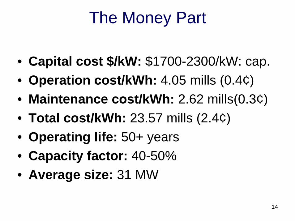
The Money Part
• Capital cost $/kW: $1700-2300/kW: cap. • Operation cost/kWh: 4.05 mills (0.4¢) • Maintenance cost/kWh: 2.62 mills(0.3¢) • Total cost/kWh: 23.57 mills (2.4¢) • Operating life: 50+ years • Capacity factor: 40-50% • Average size: 31 MW
14
Types of Hydropower
Facilities
15
• Impoundment Hydropower- uses a dam to store water. Water may be released either to meet changing electricity needs or to maintain a constant water level.
16
• Run-of-River Projects - utilize the flow of water within the natural range of the river, requiring little or no impoundment. Run-of-river plants can be designed using large flow rates with low head or small flow rates with high head
17
• Microhydropower Projects - produce 300 kilowatts (kW) or less. Microhydroplants can utilize low heads or high heads
18
• Diversion Hydropower - channels a portion of the river through a canal or penstock, but may require a dam
19
Pumped storage - pumps water from a lower reservoir to an upper reservoir at times when demand for electricity is low. During periods of high electrical demand, the water is released back to the lower reservoir to generate electricity.
20
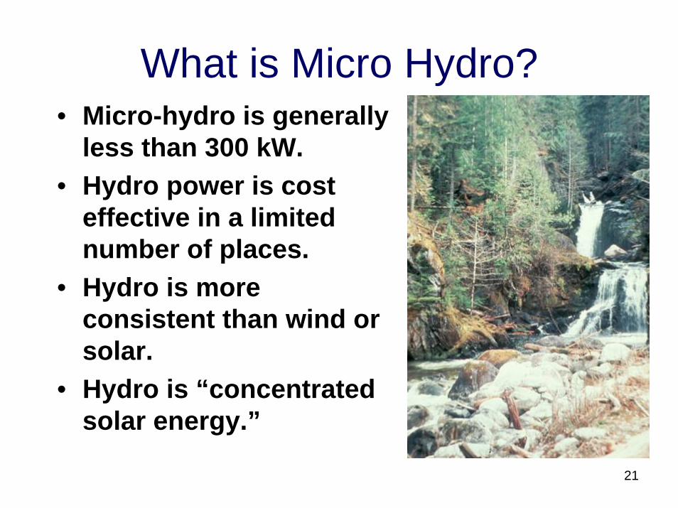
What is Micro Hydro?• Micro-hydro is generally
less than 300 kW.• Hydro power is cost
effective in a limited number of places.
• Hydro is more consistent than wind or solar.
• Hydro is “concentrated solar energy.”
21
Micro Hydro Costs
• High Capital Cost– Labor and Earth Moving Equipment– Civil Works and Penstocks
• Low Operating Cost– No Fuel– Inexpensive maintenance
• Especially economic for Do-It-Yourself.
22
Micro Hydro is Run-of-River
• No water storage.• Much simpler to design and build.• Less environmental impact.• May be seasonally dependent.• Some schemes have a small reservoir for
supplying peak daily loads.
23
Water Rights• Sufficient water must be available.• Fish or riparian habitat must not be affected.• Other licensed users take precedence.• Environmental impact must be addressed.
– Erosion due to civil works– Water temperature increased due to low
water.– Dams are not recommended.
• Easements required if crossing private land.
24
AC systems
• River flow must exceed peak demand.• Standard wiring and electrical equipment.• Components
– Generator• Induction• Synchronous
– Frequency Control and Governors– Voltage Control – Diversion loads
25
Off-Grid AC systems
• River flow must exceed peak demand.• Standard wiring and electrical equipment.• Components
– Generator– Frequency Control and Governors– Voltage Control – Diversion loads
26
DC Systems
• Makes low power sites feasible.• Run-of-river with storage in batteries.• Components:
– Generators/Alternators– Batteries– Charge Control – Diversion loads– Inverters
27
AC vs. DC• Amount of Power
– 2 kW or 3 kW required for AC systems not tied to grid• Energy Storage with Batteries
– Surge and peak loads may exceed capacity• Complexity
– Batteries require maintenance• Convenience
– AC appliances are common and inexpensive• Transmission
– AC voltage is easier to change
28
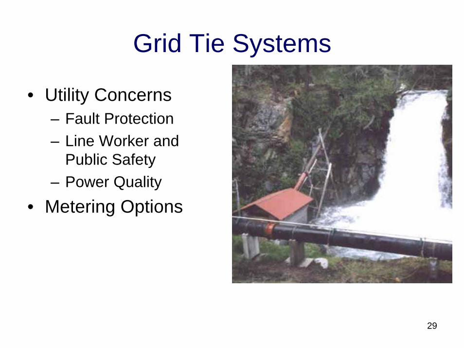
Grid Tie Systems
• Utility Concerns– Fault Protection– Line Worker and
Public Safety– Power Quality
• Metering Options
29
Line Worker and Public Safety
• Islanding– Generator supplies an isolated portion of grid
during a power outage.– Poses safety hazard to line workers.– Inverters meet UL standards– Induction Generators (Motors)
• Out of Synchronize Close• Accessible, lockable, visible-break switch
30
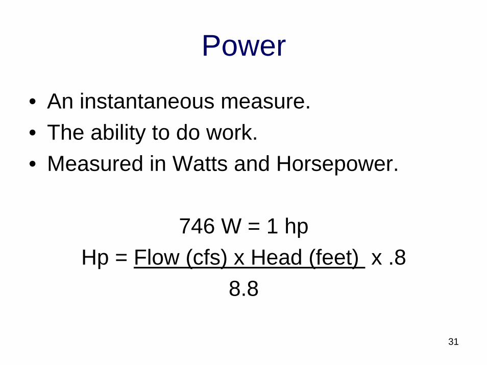
Power
• An instantaneous measure.• The ability to do work.• Measured in Watts and Horsepower.
746 W = 1 hpHp = Flow (cfs) x Head (feet) x .8
8.8
31
Hydro Power
• Site Assessment – potential power• Loads – required power• System capacity – designed power• Locating the Intake• Locating the Powerhouse
32
Site Assessment• Flow
– The design flow will be a percentage of the measured stream flow.
– Design flow determines penstock size– Design flow determines nozzle size
• Head- Elevation difference between the penstock
intake and the turbine• Penstock length.
– Often the major cost.33
Loads
• Electric hot water accounts for 40%.• The clothes dryer and stove are 20%.• Fuel or solar heating must also be used if
hydro potential is less than 1000 W.• Load voltage, frequency and phase must
match the generator.
34
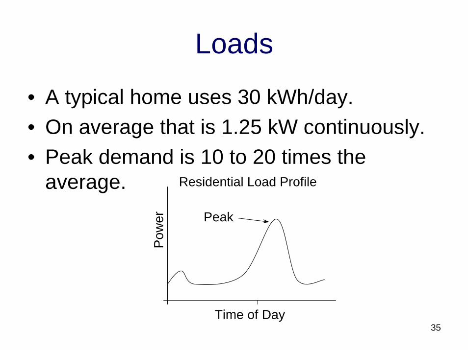
Loads
• A typical home uses 30 kWh/day.• On average that is 1.25 kW continuously.• Peak demand is 10 to 20 times the
average.
Time of Day
Pow
er
Residential Load Profile
Peak
35
Capacity and Cost
• Turbine and Generator costs increase slowly relative to capacity.
• Penstock costs increase more rapidly with increasing capacity.
• Generally, as capacity increases, cost per kW decreases.
• It is usually more economical to install as greater capacity and run heating loads.
36
Measuring Flow
• Velocity-Area Method• Velocity Head• Flow Meter• Weir method• Bucket method
37
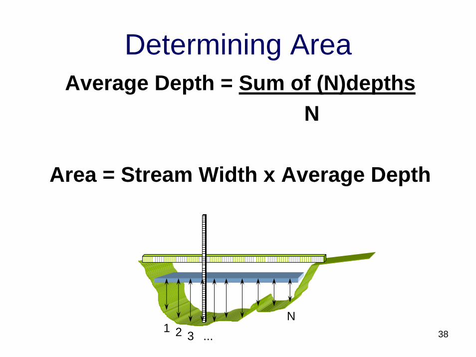
Determining AreaAverage Depth = Sum of (N)depths
N
Area = Stream Width x Average Depth
1 2 3 ...
N38
Velocity-Area Method
• Measures the volume of water flowing across a cross section of the stream.
Flow = area x average stream velocity
39
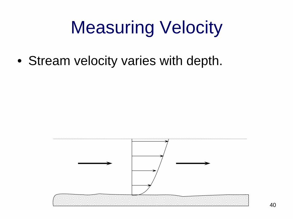
Measuring Velocity
• Stream velocity varies with depth.
40
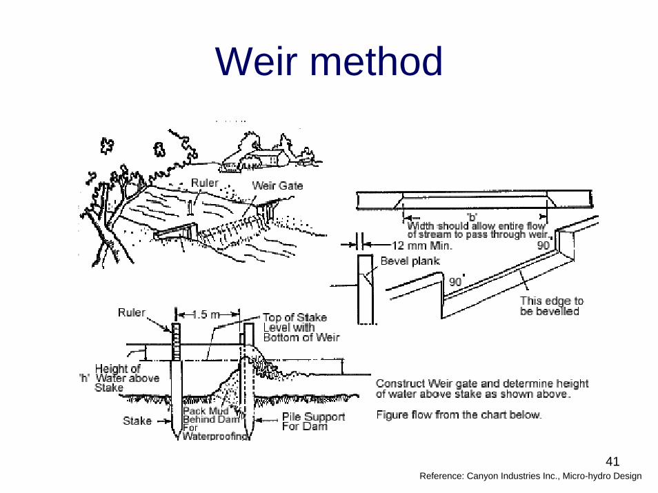
Weir method
41Reference: Canyon Industries Inc., Micro-hydro Design
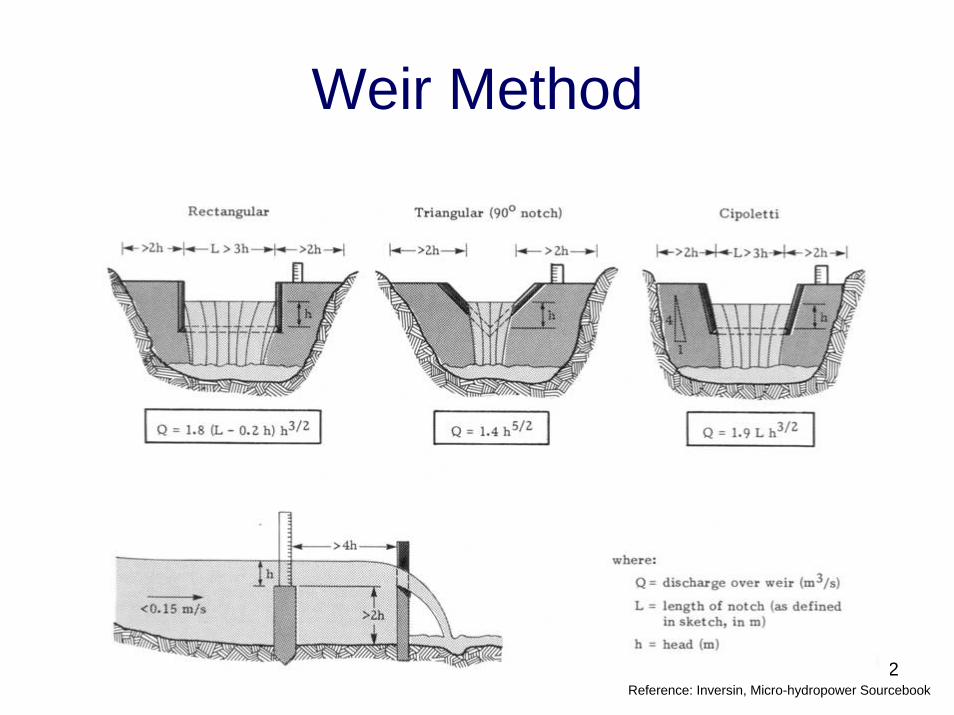
Weir Method
42Reference: Inversin, Micro-hydropower Sourcebook
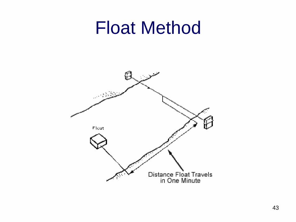
Float Method
43
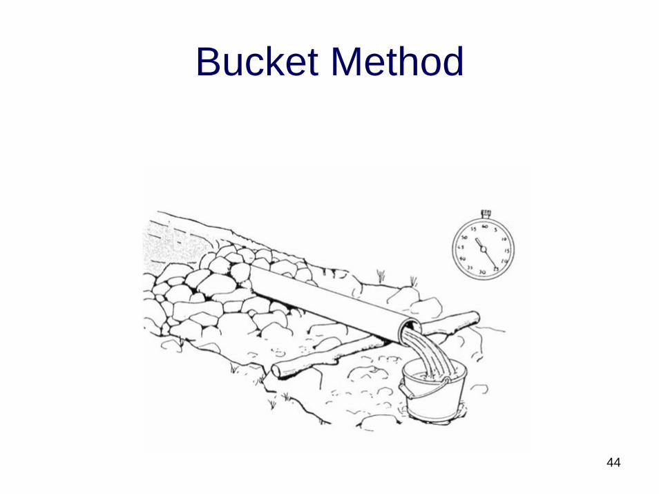
Bucket Method
44
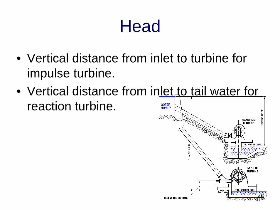
Head
45
• Vertical distance from inlet to turbine for impulse turbine.
• Vertical distance from inlet to tail water for reaction turbine.
Measuring Head
• Inclinometer• Altimeter• Hose and Pressure gauge• Level
46
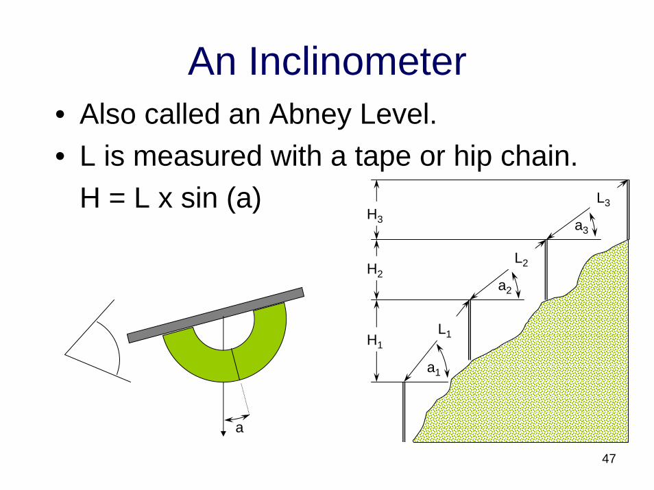
An Inclinometer• Also called an Abney Level.• L is measured with a tape or hip chain.
H = L x sin (a)H3
H2
H1L1
L3
L2
a1
a2
a3
a
47
Altimeters
• Measuring relative height, therefore absolute calibration is not necessary.
• The interval between measurements must be short to avoid error from weather changes.
• Best to take multiple readings.
48
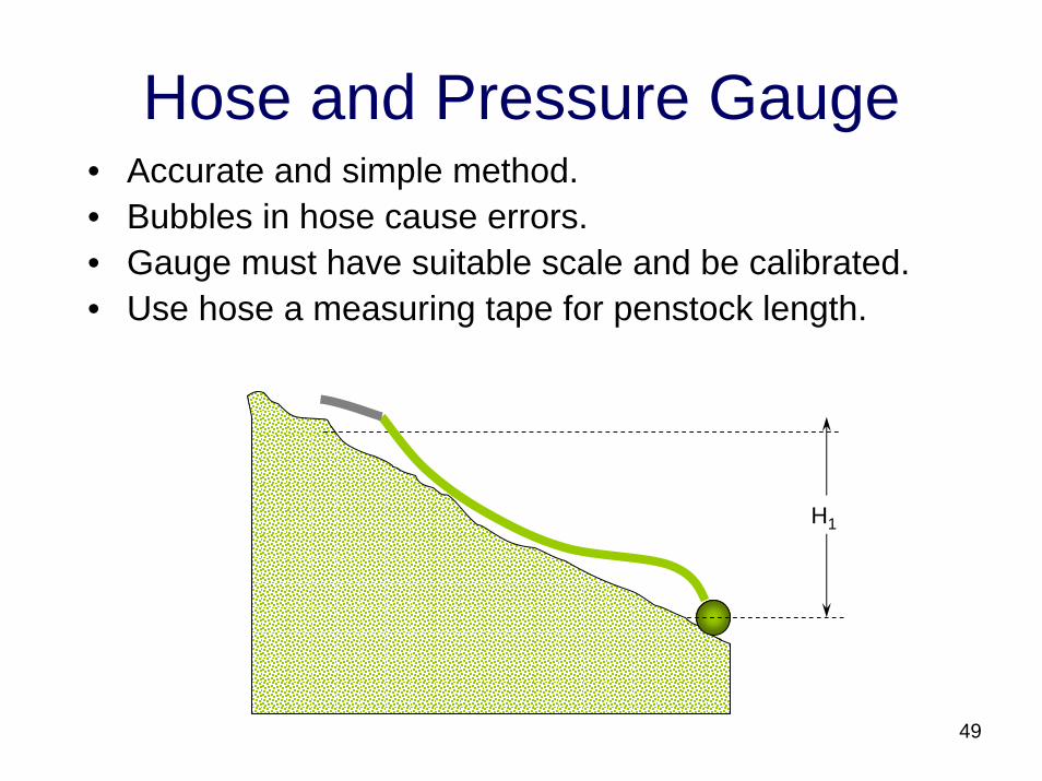
Hose and Pressure Gauge• Accurate and simple method.• Bubbles in hose cause errors.• Gauge must have suitable scale and be calibrated.• Use hose a measuring tape for penstock length.
H1
49
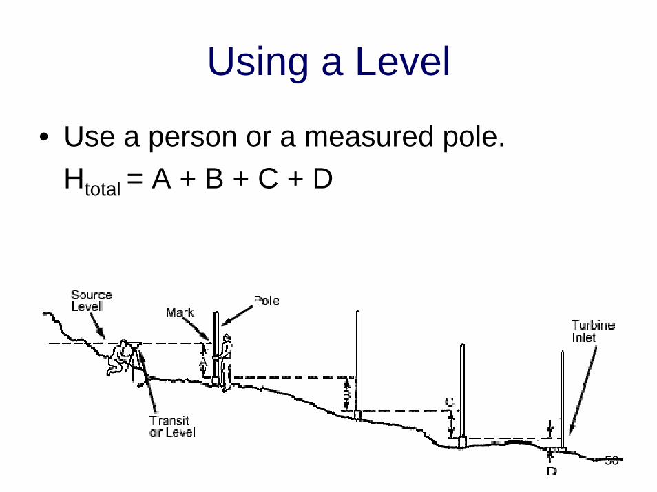
Using a Level
• Use a person or a measured pole.Htotal = A + B + C + D
50
Static Head vs. Net Head
• Static head is the vertical distance from the intake to the power house
• Net head takes into account friction loss• Pipe sizing – rule of thumb
A pipe diameter should be chosen so that only 10 – 15% of the static head is lost in pipe
friction. Tables are available for every pipe material, diameter and flow rate.
51
Locating the Intake
• Choose a site with a stable stream bed.– Constant flow stream– Bedrock– Small gradient
• The inside of bends accumulate sediment.• The outside of bends are subject to
erosion and flood damage.• Place the intake along a straight section.
52
Intake and Powerhouse
• Flood conditions must be planned for.• Composition and nature of stream bed
determines erosion and future path changes.
• Natural features can protect civil works.• Locate upstream to avoid competing with
other water users.• Access for construction and maintenance.
53
Locating the Powerhouse
• Power house must be above flood height.• To maximize head:
– Place the turbine below the powerhouse floor.– Use draft tubes.
• Locate powerhouse on inside of bends.• Use natural features for protection.• Tail race oriented downstream.• May be some distance from stream.
54
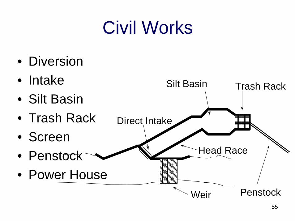
Civil Works
• Diversion• Intake• Silt Basin• Trash Rack• Screen• Penstock• Power House
Weir
Direct Intake
Head Race
Trash RackSilt Basin
Penstock55
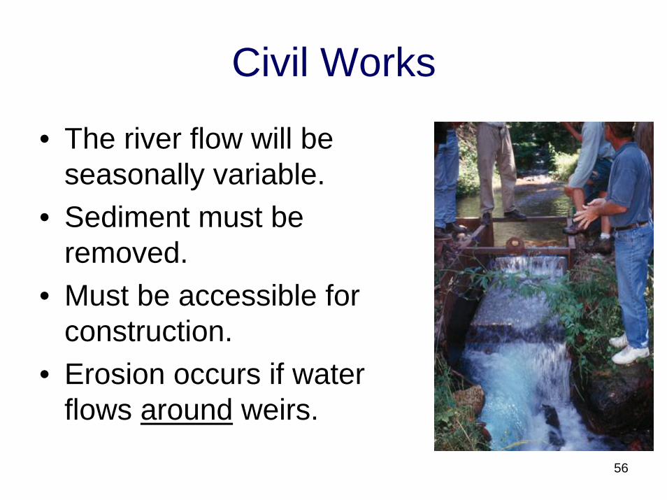
Civil Works
• The river flow will be seasonally variable.
• Sediment must be removed.
• Must be accessible for construction.
• Erosion occurs if water flows around weirs.
56
Diversion
• Weirs maintain the water level at the intake.
• A Weir does not store water.• Natural riverbed features may be used.• Weirs may also be :
– Concrete– Gabions– Wood
57
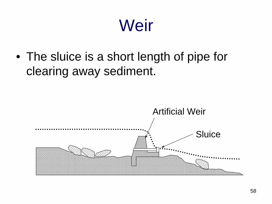
Weir
• The sluice is a short length of pipe for clearing away sediment.
Artificial Weir
Sluice
58
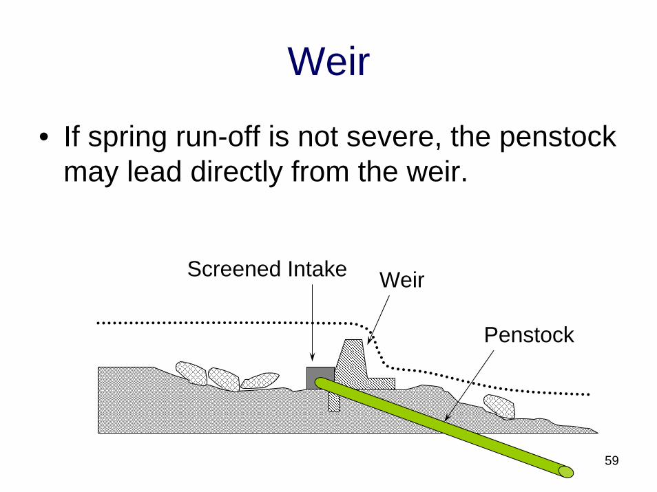
Weir
• If spring run-off is not severe, the penstock may lead directly from the weir.
Screened Intake Weir
Penstock
59
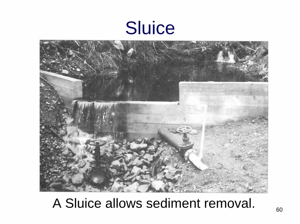
Sluice
A Sluice allows sediment removal. 60
Wing Walls
• Wing walls prevent erosion and flood damage to the civil works.
• Natural rock walls along a stream can serve the same purpose.
• Walls may be built from:– Gabions– Concrete– Rock and mortar– Wood
61
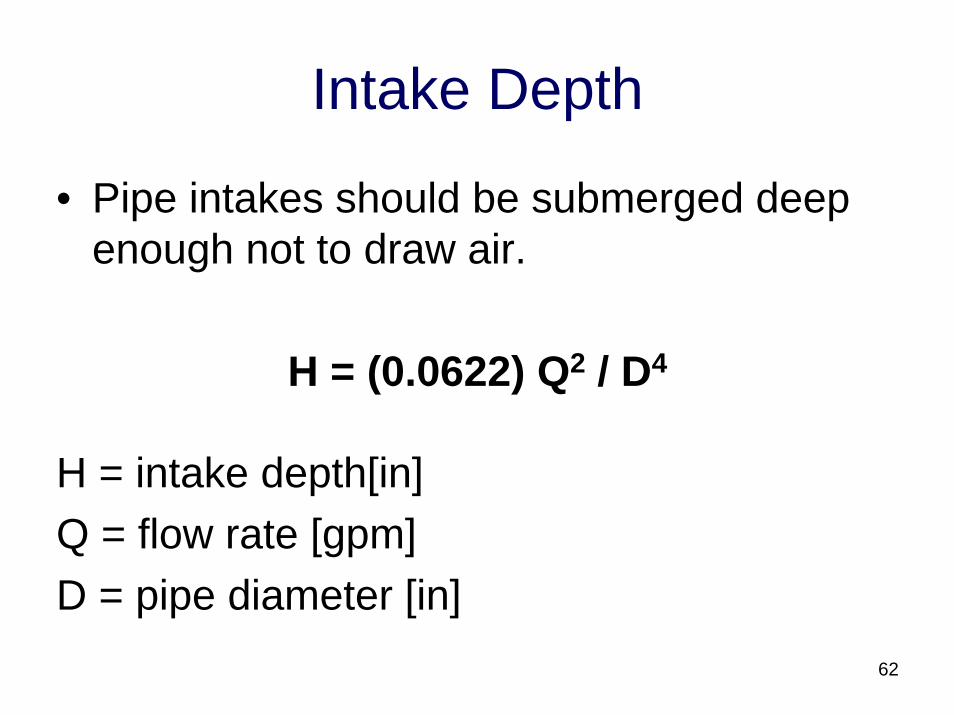
Intake Depth
• Pipe intakes should be submerged deep enough not to draw air.
H = (0.0622) Q2 / D4
H = intake depth[in]Q = flow rate [gpm]D = pipe diameter [in]
62
Intake Depth
• Rule of thumb – pipe should be submerged 3x the pipe diameter
• Screening is the weak point• Coanda effect intake boxes work well• Intake structures are the most
maintenance intensive part of hydro
63
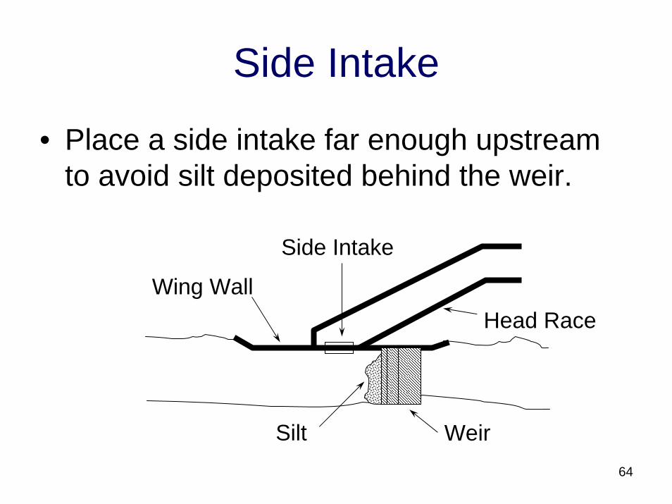
Side Intake
• Place a side intake far enough upstream to avoid silt deposited behind the weir.
Head Race
Weir
Side Intake
Wing Wall
Silt64
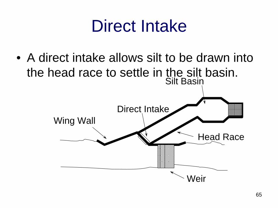
Direct Intake
• A direct intake allows silt to be drawn into the head race to settle in the silt basin.
Weir
Direct Intake
Head Race
Silt Basin
Wing Wall
65
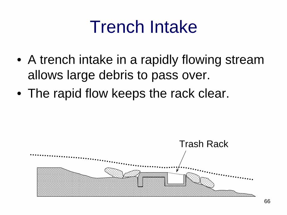
Trench Intake
• A trench intake in a rapidly flowing stream allows large debris to pass over.
• The rapid flow keeps the rack clear.
Trash Rack
66
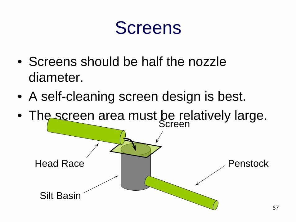
Screens
• Screens should be half the nozzle diameter.
• A self-cleaning screen design is best.• The screen area must be relatively large.
Screen
PenstockHead Race
Silt Basin67
Trash Rack• The trash rack should be at least two pipe
diameters from the pipe inlet.• If the trash rack is not situated in the main
stream it is easier to clean.• If the head race is a pipe a rack is
necessary.• Drilled PVC Pipe will serve as a trash rack.
68
Ice and Snow
69
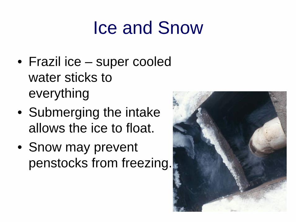
• Frazil ice – super cooled water sticks to everything
• Submerging the intake allows the ice to float.
• Snow may prevent penstocks from freezing.
Penstock
70
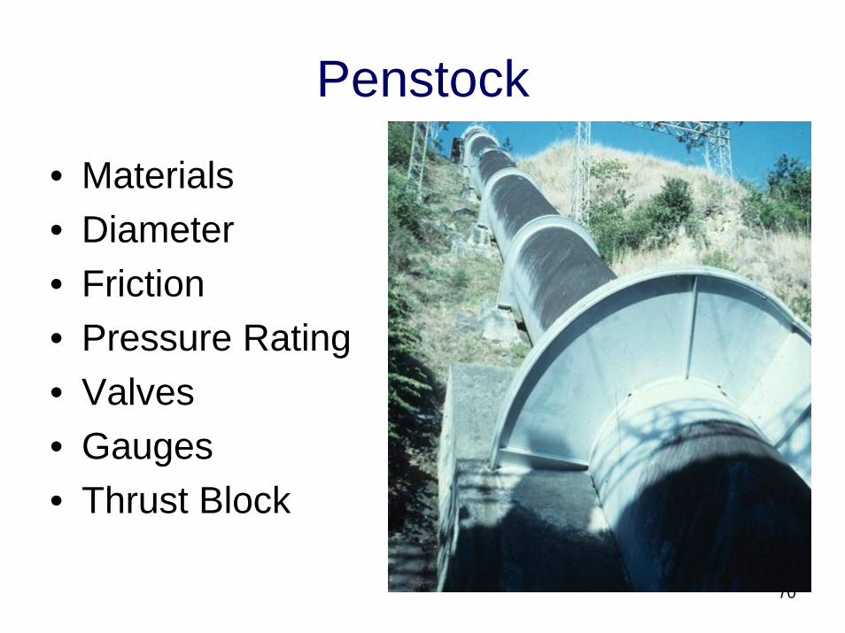
• Materials• Diameter• Friction• Pressure Rating• Valves• Gauges• Thrust Block
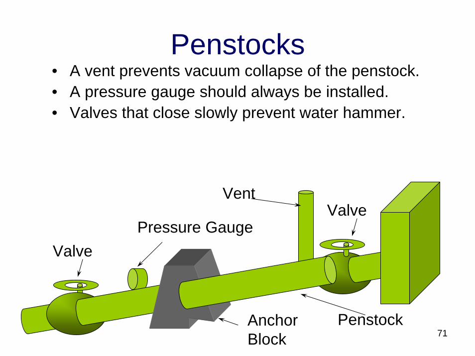
Penstocks• A vent prevents vacuum collapse of the penstock.• A pressure gauge should always be installed.• Valves that close slowly prevent water hammer.
71Penstock
ValveVent
Pressure GaugeValve
Anchor Block
Penstocks
• A short straight penstock is least expensive.
• A channel or culvert may be used to reduce penstock length.
• Pipe laid in the creek will abrade.• Penstocks deliver water under pressure.• Usually the major expense.
72
Penstock design
• It is more economical to use lower pressure rated pipe at the top of the penstock.
• Snow may insulate pipes laid above ground.
• Flow rate is determined by the nozzle at the penstock outlet.
• Maximum power delivery occurs when friction losses are 33% of gross head.
73
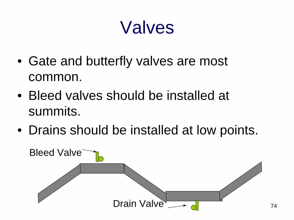
Valves
• Gate and butterfly valves are most common.
• Bleed valves should be installed at summits.
• Drains should be installed at low points.Bleed Valve
Drain Valve 74
Valve Closing Time
• Depends on operating pressure, schedule of pipe and length of pipe.
• The longer the pipe the longer the time.• Typically in the 5 to 15 second range for
up to 2000 feet of pipe.
75
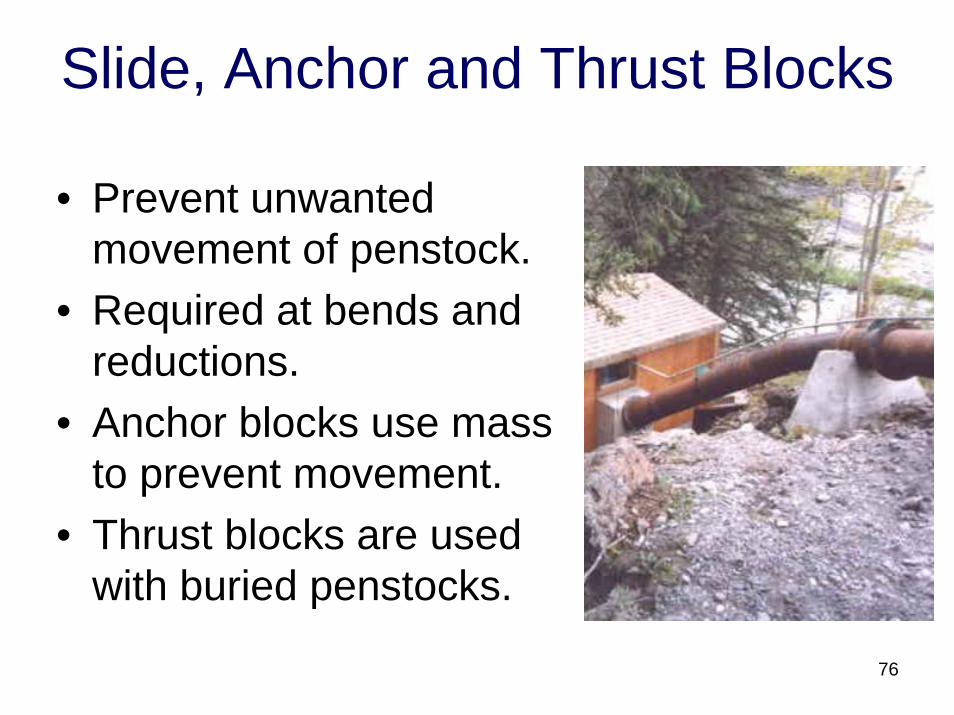
Slide, Anchor and Thrust Blocks
• Prevent unwanted movement of penstock.
• Required at bends and reductions.
• Anchor blocks use mass to prevent movement.
• Thrust blocks are used with buried penstocks.
76
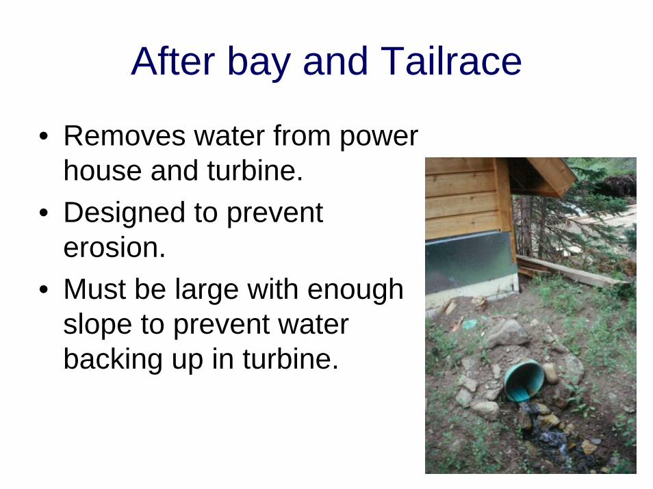
After bay and Tailrace
• Removes water from power house and turbine.
• Designed to prevent erosion.
• Must be large with enough slope to prevent water backing up in turbine.
77
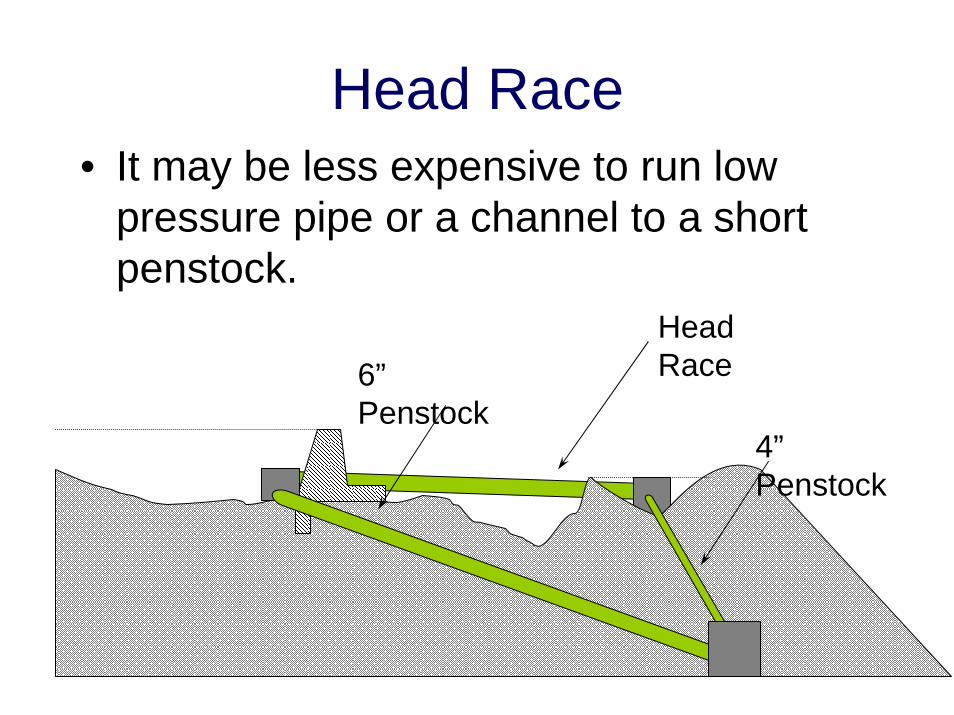
Head Race• It may be less expensive to run low
pressure pipe or a channel to a short penstock.
78
4”Penstock
6”Penstock
Head Race
Recommended