INS: Inertial Navigation
SystemsAn overview of 4 sensors
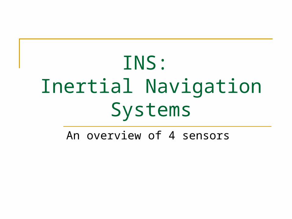
What is an INS?
Position (dead reckoning) Orientation (roll, pitch, yaw) Velocities Accelerations
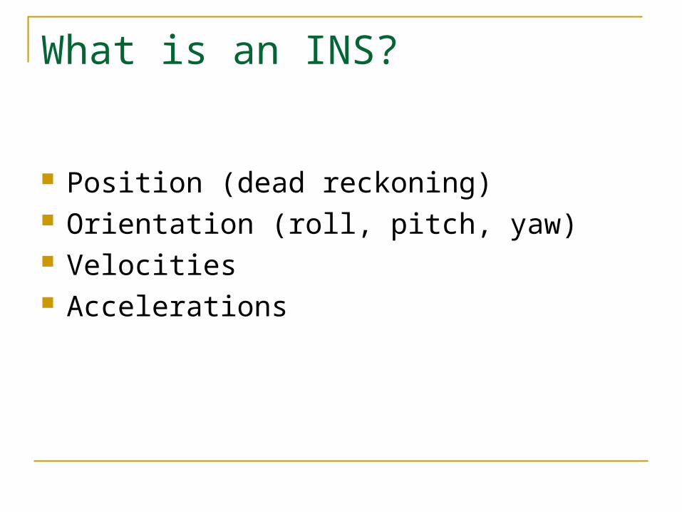
Sampling of INS Applications
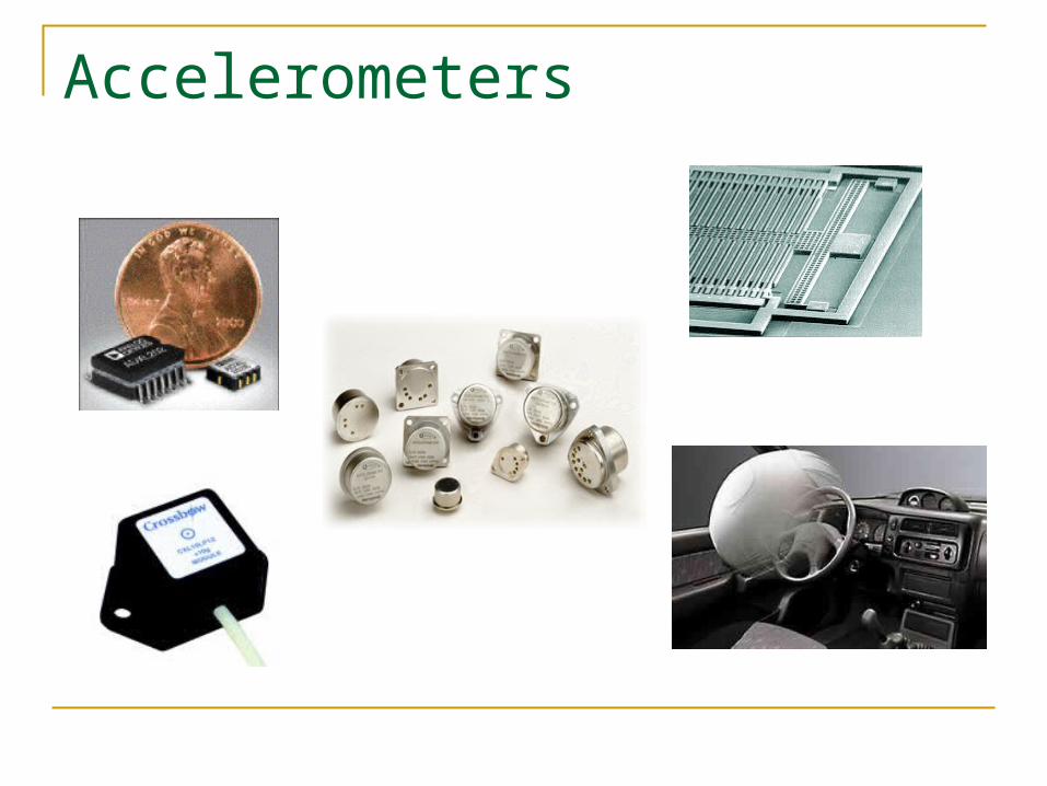
Accelerometers
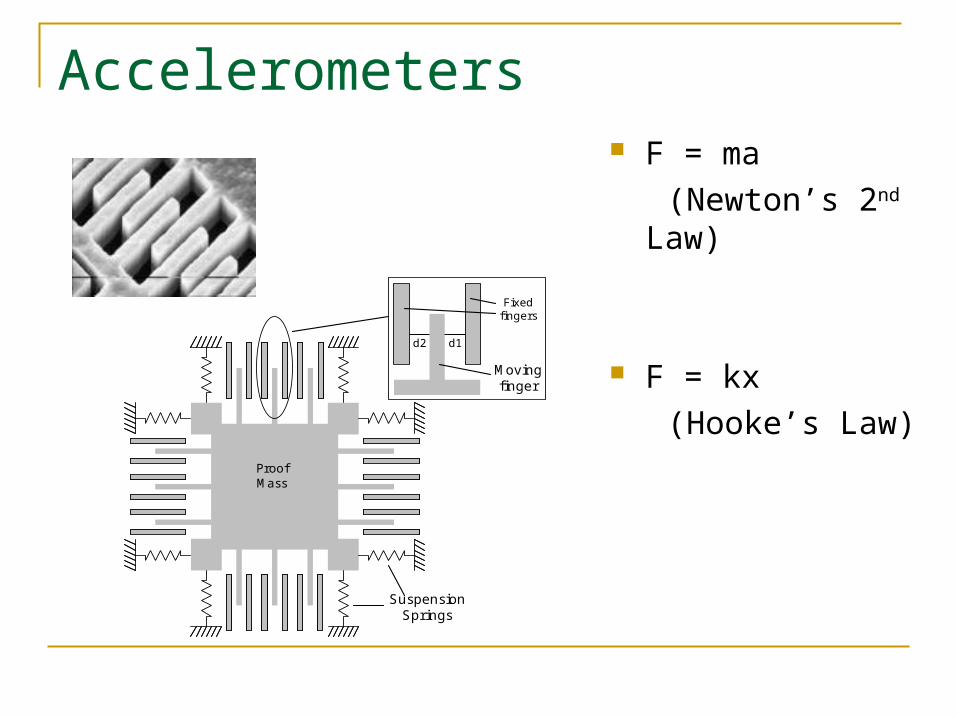
Accelerometers
Proof Mass
d1d2
Fixed fingers
Moving finger
Suspension Springs
F = ma
(Newton’s 2nd Law)
F = kx
(Hooke’s Law)
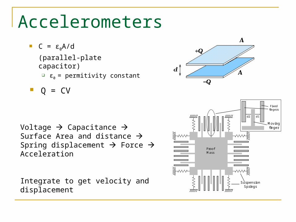
Accelerometers
Proof Mass
d1d2
Fixed fingers
Moving finger
Suspension Springs
C = ε0A/d
(parallel-plate capacitor) ε0 = permitivity constant
Voltage Capacitance Surface Area and distance Spring displacement Force Acceleration
Integrate to get velocity and displacement
Q = CV
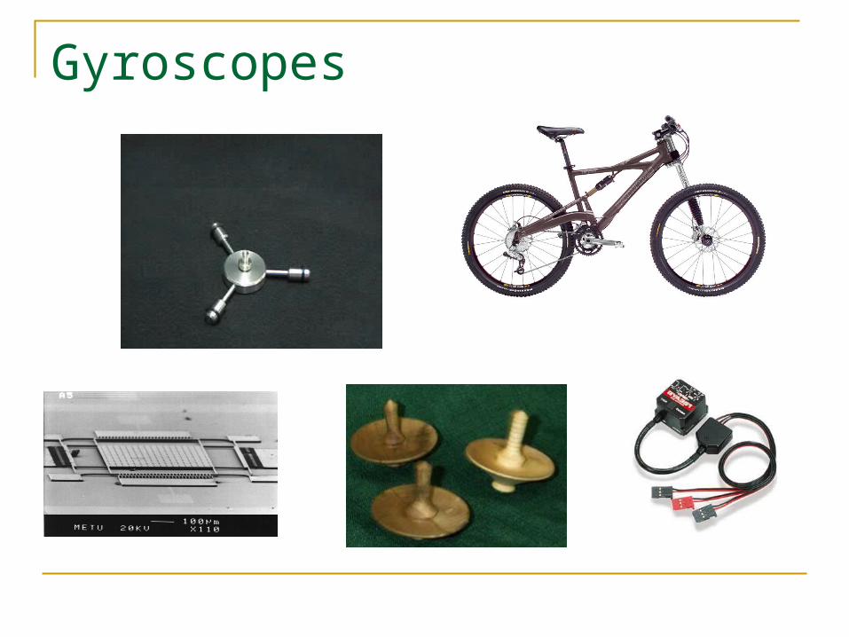
Gyroscopes
Gyroscopes
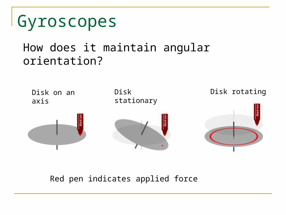
How does it maintain angular orientation?
Disk on an axis Disk stationary Disk rotating
Red pen indicates applied force
Gyroscopes – Precession
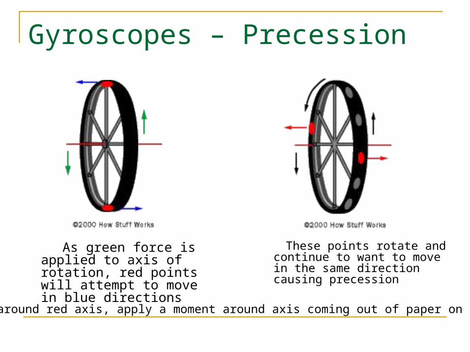
As green force is applied to axis of rotation, red points will attempt to move in blue directions
These points rotate and continue to want to move in the same direction causing precession
Rotating around red axis, apply a moment around axis coming out of paper on red axis
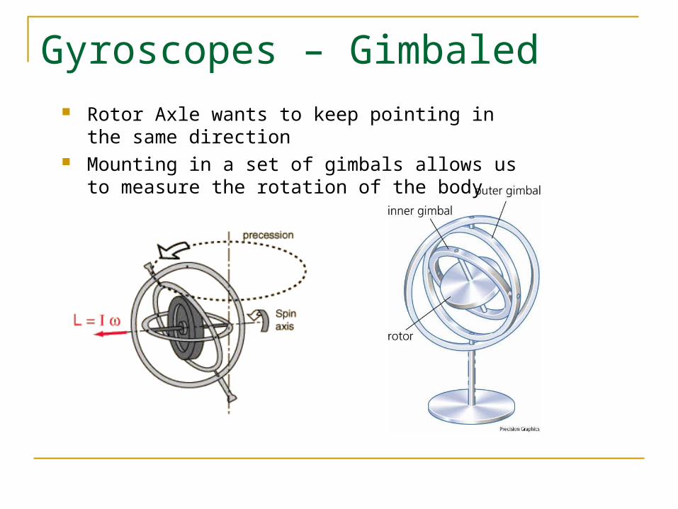
Gyroscopes – Gimbaled Rotor Axle wants to keep pointing in the same
direction Mounting in a set of gimbals allows us to measure
the rotation of the body
Gyroscopes – MEMS
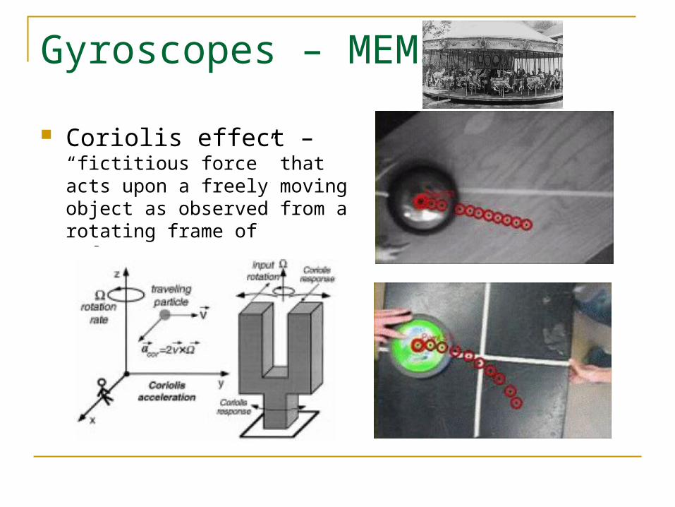
Coriolis effect – “fictitious force” that acts upon a freely moving object as observed from a rotating frame of reference
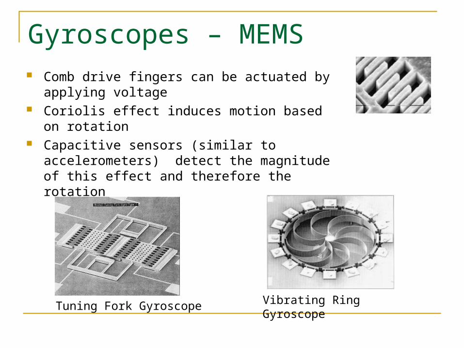
Gyroscopes – MEMS Comb drive fingers can be actuated by applying
voltage Coriolis effect induces motion based on rotation Capacitive sensors (similar to accelerometers)
detect the magnitude of this effect and therefore the rotation
Tuning Fork Gyroscope Vibrating Ring Gyroscope
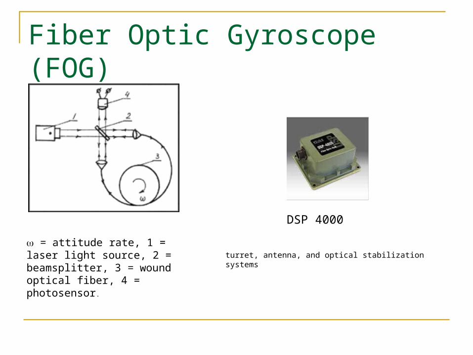
Fiber Optic Gyroscope (FOG)
= attitude rate, 1 = laser light source, 2 = beamsplitter, 3 = wound optical fiber, 4 = photosensor.
DSP 4000
turret, antenna, and optical stabilization systems
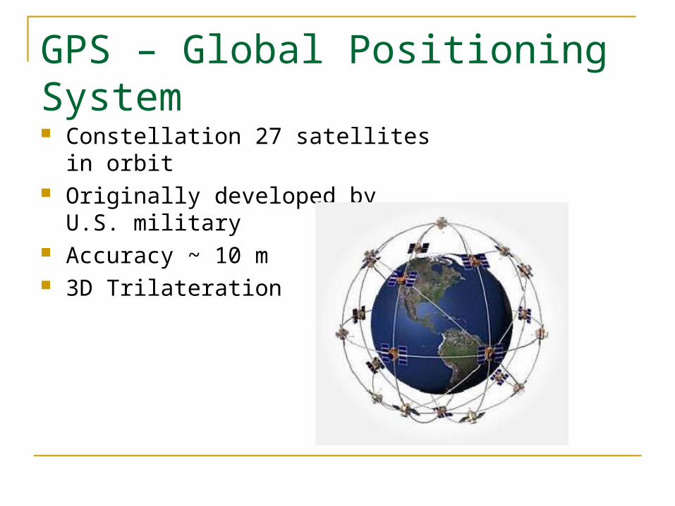
GPS – Global Positioning System Constellation 27 satellites in orbit Originally developed by U.S. military Accuracy ~ 10 m 3D Trilateration
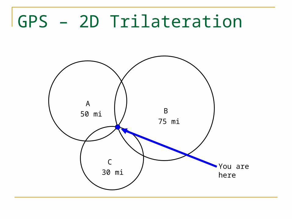
GPS – 2D Trilateration
AB
CYou are here
50 mi75 mi
30 mi
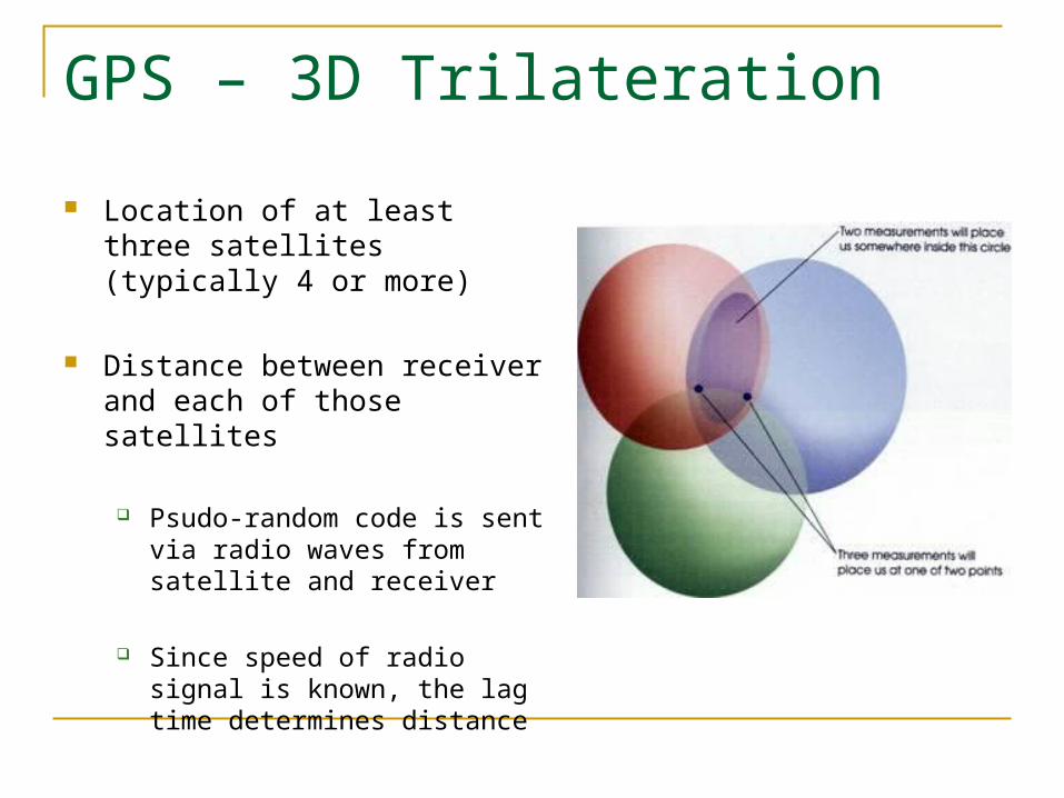
GPS – 3D Trilateration
Location of at least three satellites (typically 4 or more)
Distance between receiver and each of those satellites
Psudo-random code is sent via radio waves from satellite and receiver
Since speed of radio signal is known, the lag time determines distance
GPS – Improvements
Some sources of error Earth’s atmosphere slows down signal Radio signal can bounce off large objects Misreporting of satellite location
Differential GPS (DGPS) Station with known location calculates receiver’s inaccuracy Broadcasts signal correction information Accuracy ~ 10 m
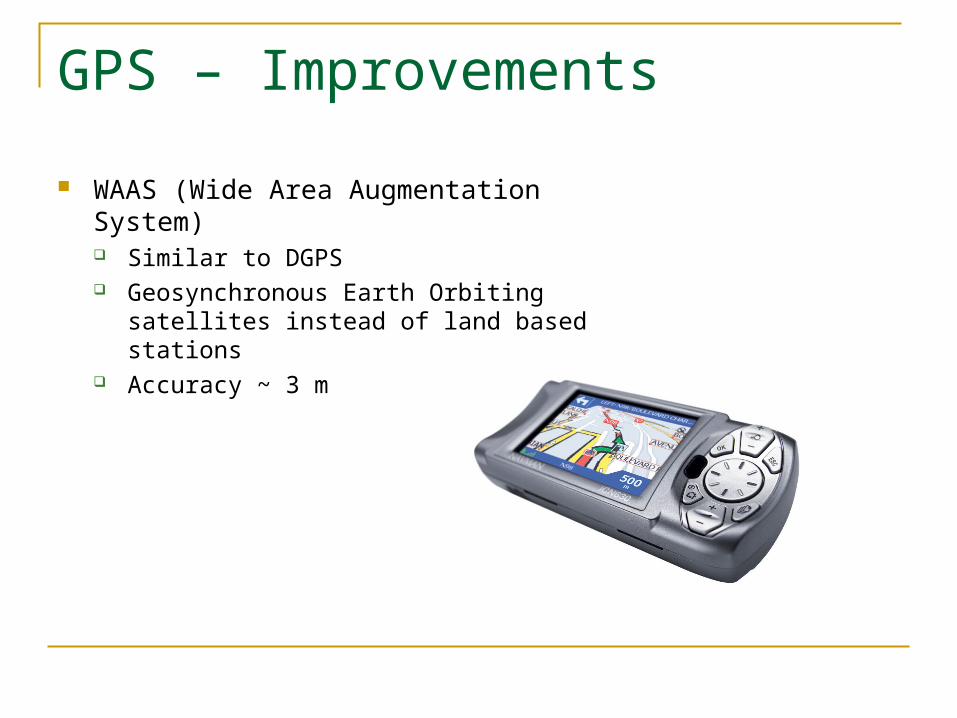
GPS – Improvements
WAAS (Wide Area Augmentation System) Similar to DGPS Geosynchronous Earth Orbiting satellites
instead of land based stations Accuracy ~ 3 m
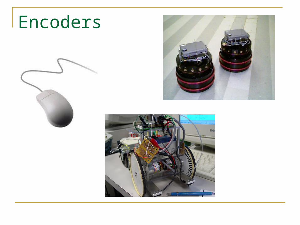
Encoders
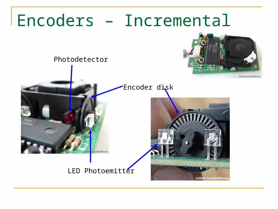
Encoders – Incremental
LED Photoemitter
Photodetector
Encoder disk
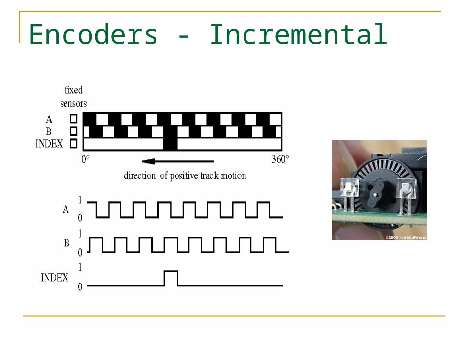
Encoders - Incremental
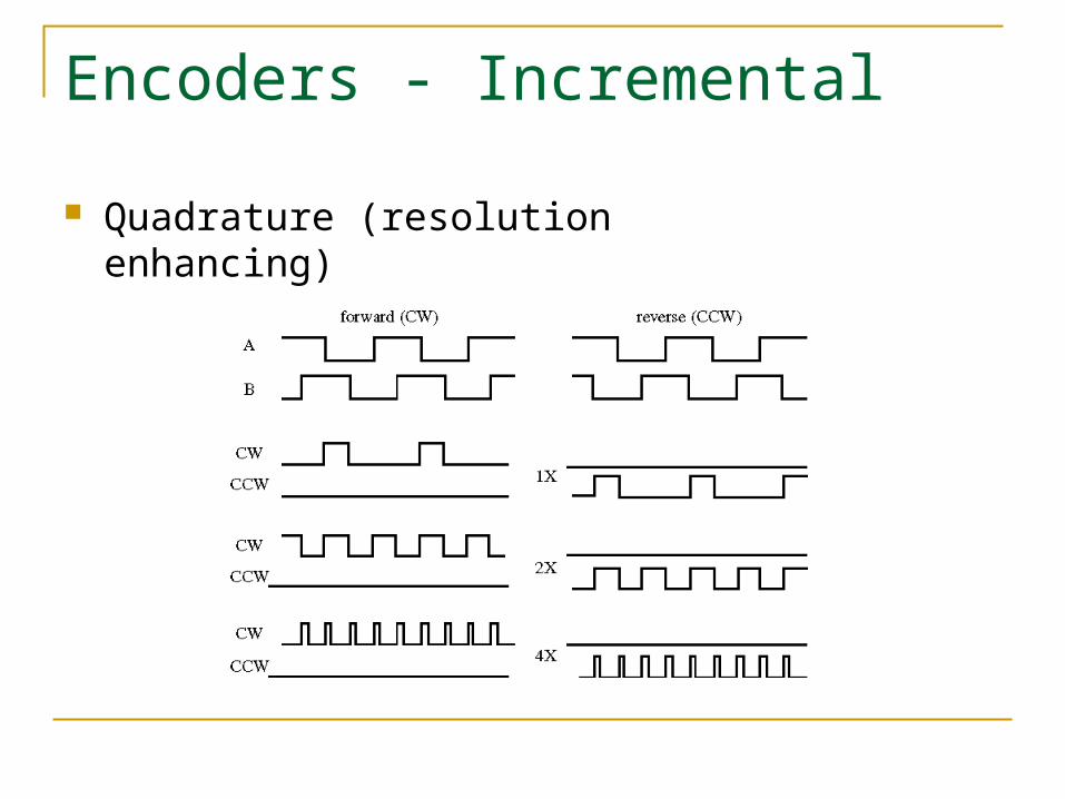
Encoders - Incremental
Quadrature (resolution enhancing)
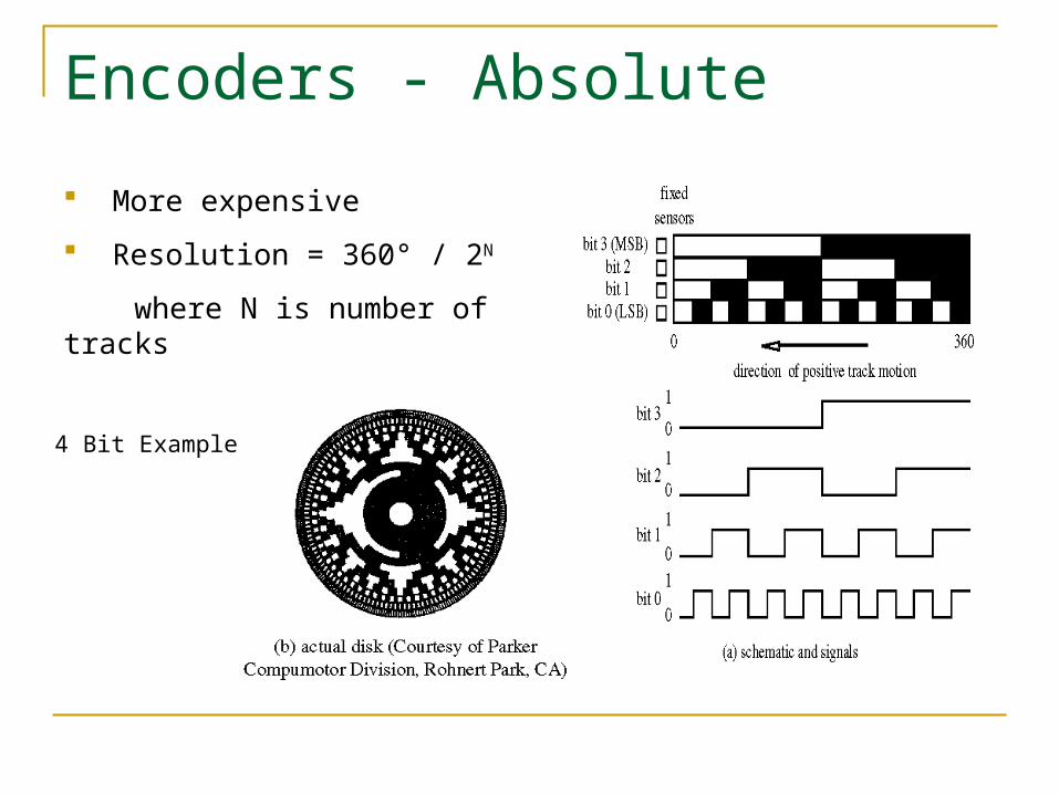
Encoders - Absolute
4 Bit Example
More expensive
Resolution = 360° / 2N
where N is number of tracks
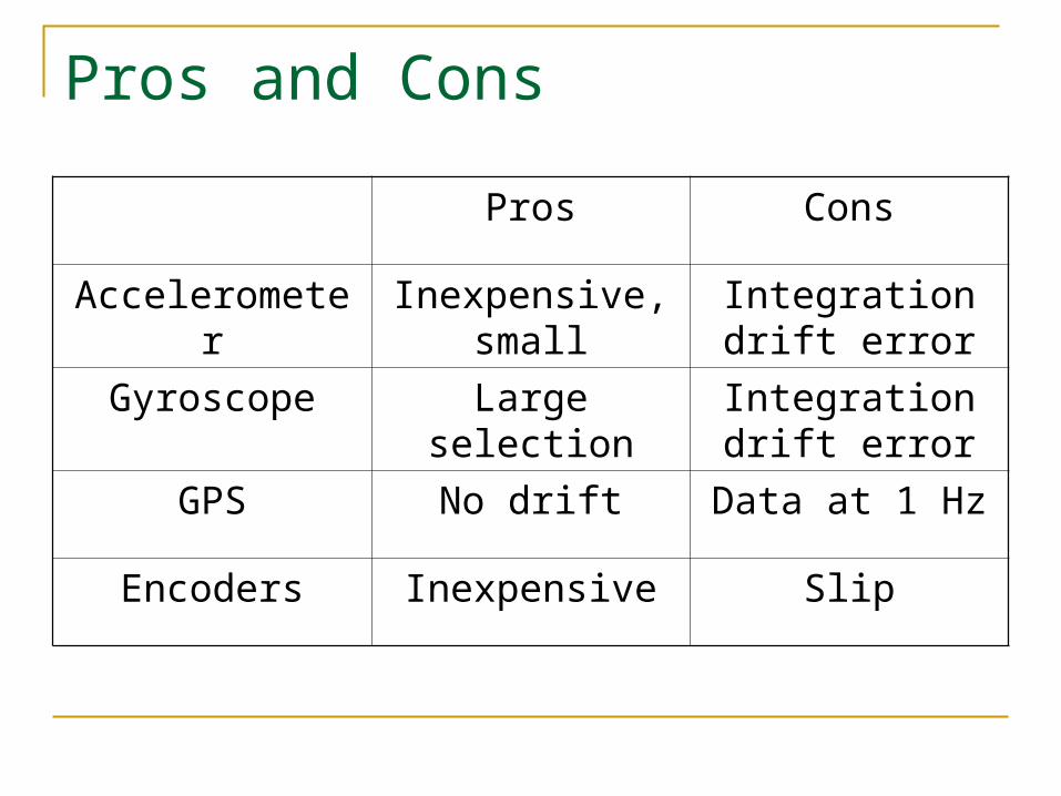
Pros and Cons
Pros Cons
Accelerometer Inexpensive, small
Integration drift error
Gyroscope Large selection Integration drift error
GPS No drift Data at 1 Hz
Encoders Inexpensive Slip
Recommended