1
Yeriel Mangin Oil and Gas Technician
[email protected] (956)701-5102
Lease Operator
11 Steps to follow
2
Yeriel Mangin Oil and Gas Technician
[email protected] (956)701-5102
Content
Objective………………………………………………………………………………………………………………. 3
Introduction………………………………………………………………………………………………………….. 3
Step to follow in a facility …………………………………………………………………………………… 4, 5
Safety……………………………………………………………………………………………………………………. 6
Equipment and function “The Wellhead”………………….……………………………………………. 7
Equipment and function “Heater”…………………………………………………………………………. 8
Safety Equipment…………………………………………………………………………………………………...9
High and Low Pressure Separator…………………………………………………………………………… 10
Chemical Tank………………………………………………………………………………………………………….11
Clean Facility…………………………………………………………………………………………………………….11
Stock Tanks…………………………………………………………………………………………………………….. 12
The Rock…………………………………………………………………………………………………………………. 12
Data………………………………………………………………………………………………………………………… 12
Troubleshooting…………………………………………………………………………………………………….…13
Reference.………………………………………………………………………………………………………………. 14
3
Yeriel Mangin Oil and Gas Technician
[email protected] (956)701-5102
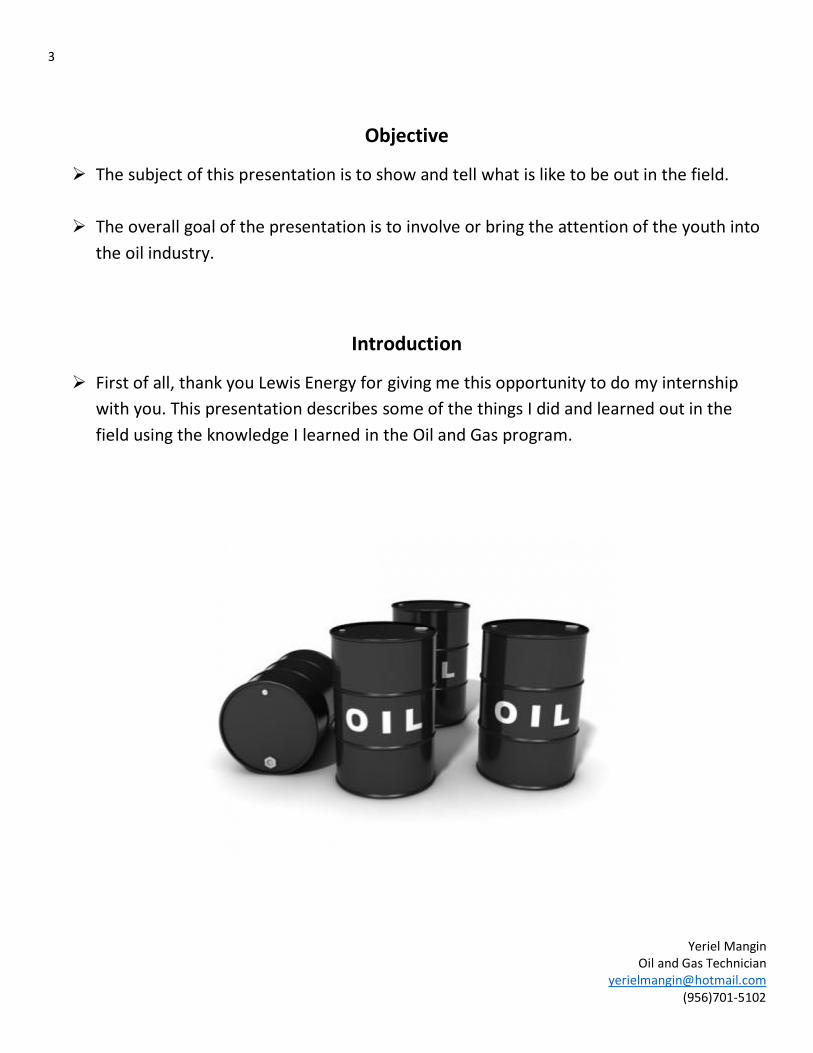
Objective
The subject of this presentation is to show and tell what is like to be out in the field.
The overall goal of the presentation is to involve or bring the attention of the youth into
the oil industry.
Introduction
First of all, thank you Lewis Energy for giving me this opportunity to do my internship
with you. This presentation describes some of the things I did and learned out in the
field using the knowledge I learned in the Oil and Gas program.
4
Yeriel Mangin Oil and Gas Technician
[email protected] (956)701-5102
Steps to Follow in a Facility
1. Safety
Personal Protective Equipment (PPE)
Equipment maintenance or repairs
Proper Communication
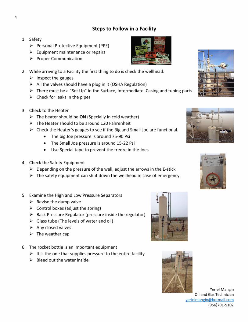
2. While arriving to a Facility the first thing to do is check the wellhead.
Inspect the gauges
All the valves should have a plug in it (OSHA Regulation)
There must be a “Set Up” in the Surface, Intermediate, Casing and tubing parts.
Check for leaks in the pipes
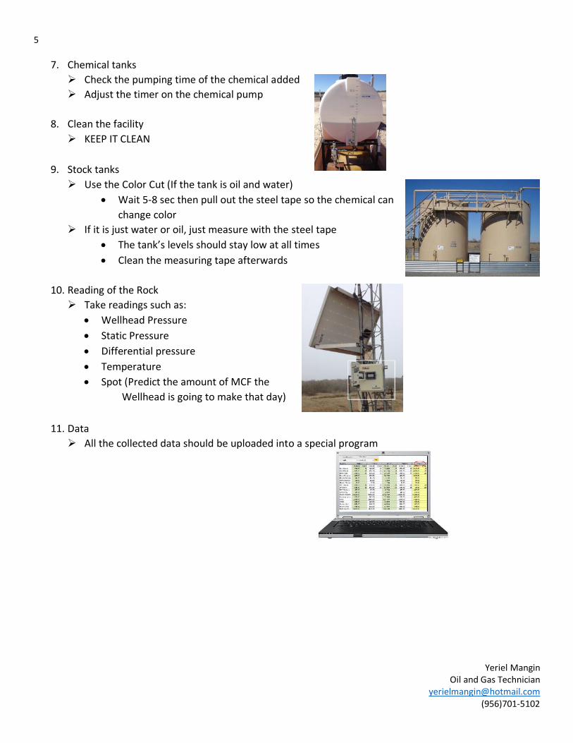
3. Check to the Heater
The heater should be ON (Specially in cold weather)
The Heater should to be around 120 Fahrenheit
Check the Heater’s gauges to see if the Big and Small Joe are functional.
The big Joe pressure is around 75-90 Psi
The Small Joe pressure is around 15-22 Psi
Use Special tape to prevent the freeze in the Joes
4. Check the Safety Equipment
Depending on the pressure of the well, adjust the arrows in the E-stick
The safety equipment can shut down the wellhead in case of emergency.
5. Examine the High and Low Pressure Separators
Revise the dump valve
Control boxes (adjust the spring)
Back Pressure Regulator (pressure inside the regulator)
Glass tube (The levels of water and oil)
Any closed valves
The weather cap
6. The rocket bottle is an important equipment
It is the one that supplies pressure to the entire facility
Bleed out the water inside
5
Yeriel Mangin Oil and Gas Technician
[email protected] (956)701-5102
7. Chemical tanks
Check the pumping time of the chemical added
Adjust the timer on the chemical pump
8. Clean the facility
KEEP IT CLEAN
9. Stock tanks
Use the Color Cut (If the tank is oil and water)
Wait 5-8 sec then pull out the steel tape so the chemical can
change color
If it is just water or oil, just measure with the steel tape
The tank’s levels should stay low at all times
Clean the measuring tape afterwards
10. Reading of the Rock
Take readings such as:
Wellhead Pressure
Static Pressure
Differential pressure
Temperature
Spot (Predict the amount of MCF the
Wellhead is going to make that day)
11. Data
All the collected data should be uploaded into a special program
6
Yeriel Mangin Oil and Gas Technician
[email protected] (956)701-5102
Safety
Personal Protective Equipment (PPE) include:
Hard Hat
Steel-toed boots
Safety glasses
Flame-Resistant (FR) Clothing
H2S Personal Monitor
Goggles
Earplugs
Communication
Poor communication is a contributing factor in many accidents.
Workers are often injured because safe work practices have not been effectively communicated.
Hazard Communication Standard (HCS) published by OSHA.
Also known as the Right to Know Law: This law gives the workers the right to know certain things
about the chemicals they work with or are exposed to.
The most effective way of reducing industry injuries and incidents is to understand the risks involve
with all the hazards and work activities.
Hydrogen Sulfide (H2S)
Highly toxic, colorless gas that is formed by the decay of organic materials.
It is one of the leading causes of sudden dead in the oil industry.
It can be fatal at levels 750-1000 ppm.
Specific training is required to work or enter an H2S environment.
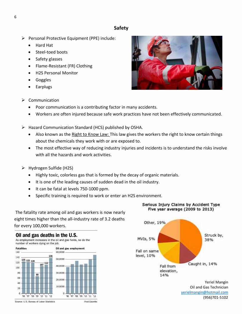
The fatality rate among oil and gas workers is now nearly
eight times higher than the all-industry rate of 3.2 deaths
for every 100,000 workers.
7
Yeriel Mangin Oil and Gas Technician
[email protected] (956)701-5102
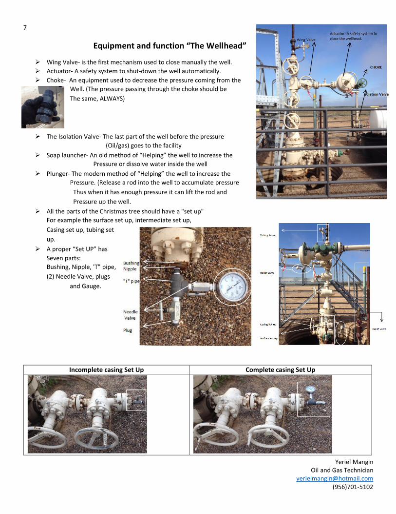
Equipment and function “The Wellhead”
Wing Valve- is the first mechanism used to close manually the well.
Actuator- A safety system to shut-down the well automatically.
Choke- An equipment used to decrease the pressure coming from the
Well. (The pressure passing through the choke should be
The same, ALWAYS)
The Isolation Valve- The last part of the well before the pressure
(Oil/gas) goes to the facility
Soap launcher- An old method of “Helping” the well to increase the
Pressure or dissolve water inside the well
Plunger- The modern method of “Helping” the well to increase the
Pressure. (Release a rod into the well to accumulate pressure
Thus when it has enough pressure it can lift the rod and
Pressure up the well.
All the parts of the Christmas tree should have a "set up"
For example the surface set up, intermediate set up,
Casing set up, tubing set
up.
A proper “Set UP” has
Seven parts:
Bushing, Nipple, 'T" pipe,
(2) Needle Valve, plugs
and Gauge.
Incomplete casing Set Up Complete casing Set Up
8
Yeriel Mangin Oil and Gas Technician
[email protected] (956)701-5102
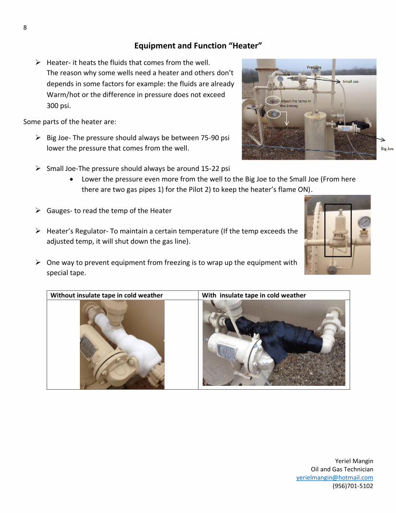
Equipment and Function “Heater”
Heater- it heats the fluids that comes from the well.
The reason why some wells need a heater and others don’t
depends in some factors for example: the fluids are already
Warm/hot or the difference in pressure does not exceed
300 psi.
Some parts of the heater are:
Big Joe- The pressure should always be between 75-90 psi
lower the pressure that comes from the well.
Small Joe-The pressure should always be around 15-22 psi
Lower the pressure even more from the well to the Big Joe to the Small Joe (From here
there are two gas pipes 1) for the Pilot 2) to keep the heater’s flame ON).
Gauges- to read the temp of the Heater
Heater’s Regulator- To maintain a certain temperature (If the temp exceeds the
adjusted temp, it will shut down the gas line).
One way to prevent equipment from freezing is to wrap up the equipment with
special tape.
Without insulate tape in cold weather With insulate tape in cold weather
9
Yeriel Mangin Oil and Gas Technician
[email protected] (956)701-5102
Safety Equipment
The safety equipment in the facility can shut down the well head automatically:
1. E-stick" boxes (2)
Adjusted a max and min pressure in the box, thus if the pressure reaches the needles, it
automatically shuts down the
wellhead.
There are two boxes:
2. Actuator:
When the "wheel" is outside
(First picture) and it has
pressure the actuator will let
pass the pressure to the next
phase (Heater/High-low
Separator).
When the "wheel" is outside
(First picture) and it does not
have pressure the actuator will shut down the wellhead.
When the "wheel" is inside (Second picture) the actuator is in by-pass, thus you can make any
arrangements you need to make.
"The purpose of the wheel is to adjust a plate inside the actuator so you can put it on by-pass or shut
down the wellhead."
3. Versa Valve
Controls the pressure that helps the actuator to stay open; you can manually or remotely close it from
the Office.
4. Pineapple
A third (floater/check) in the low pressure separator. The pineapple does not let the
(water/condensate) to get to a certain level inside the separator (It is like your back up) if the
water reaches the pineapple level it immediately shuts down the well thus the
(water/condensate) do not reaches the flare tower.
Normally right next to the Heater or Header
Right next to the High Pressure separator
First Picture Second Picture
10
Yeriel Mangin Oil and Gas Technician
[email protected] (956)701-5102
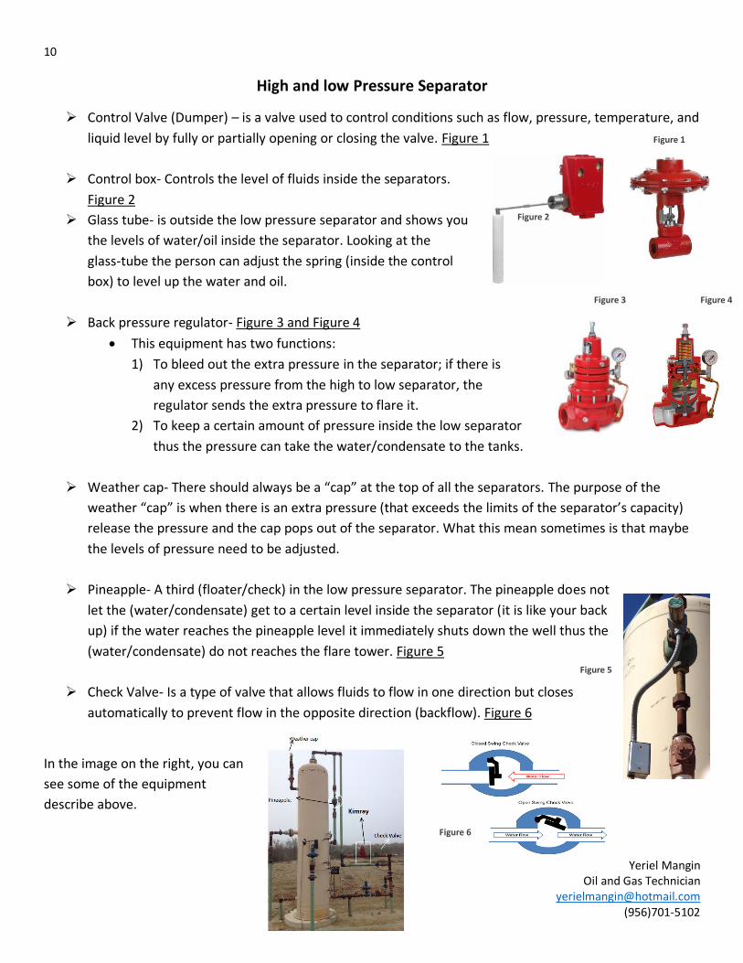
Figure 1
High and low Pressure Separator
Control Valve (Dumper) – is a valve used to control conditions such as flow, pressure, temperature, and
liquid level by fully or partially opening or closing the valve. Figure 1
Control box- Controls the level of fluids inside the separators.
Figure 2
Glass tube- is outside the low pressure separator and shows you
the levels of water/oil inside the separator. Looking at the
glass-tube the person can adjust the spring (inside the control
box) to level up the water and oil.
Back pressure regulator- Figure 3 and Figure 4
This equipment has two functions:
1) To bleed out the extra pressure in the separator; if there is
any excess pressure from the high to low separator, the
regulator sends the extra pressure to flare it.
2) To keep a certain amount of pressure inside the low separator
thus the pressure can take the water/condensate to the tanks.
Weather cap- There should always be a “cap” at the top of all the separators. The purpose of the
weather “cap” is when there is an extra pressure (that exceeds the limits of the separator’s capacity)
release the pressure and the cap pops out of the separator. What this mean sometimes is that maybe
the levels of pressure need to be adjusted.
Pineapple- A third (floater/check) in the low pressure separator. The pineapple does not
let the (water/condensate) get to a certain level inside the separator (it is like your back
up) if the water reaches the pineapple level it immediately shuts down the well thus the
(water/condensate) do not reaches the flare tower. Figure 5
Check Valve- Is a type of valve that allows fluids to flow in one direction but closes
automatically to prevent flow in the opposite direction (backflow). Figure 6
In the image on the right, you can
see some of the equipment
describe above.
Figure 2
Figure 3 Figure 4
Figure 5
Figure 6
11
Yeriel Mangin Oil and Gas Technician
[email protected] (956)701-5102
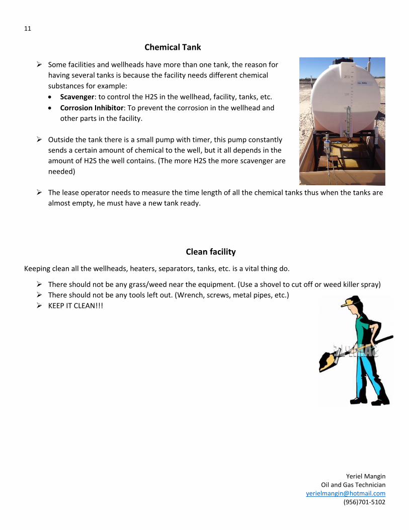
Chemical Tank
Some facilities and wellheads have more than one tank, the reason for
having several tanks is because the facility needs different chemical
substances for example:
Scavenger: to control the H2S in the wellhead, facility, tanks, etc.
Corrosion Inhibitor: To prevent the corrosion in the wellhead and
other parts in the facility.
Outside the tank there is a small pump with timer, this pump constantly
sends a certain amount of chemical to the well, but it all depends in the
amount of H2S the well contains. (The more H2S the more scavenger are
needed)
The lease operator needs to measure the time length of all the chemical tanks thus when the tanks are
almost empty, he must have a new tank ready.
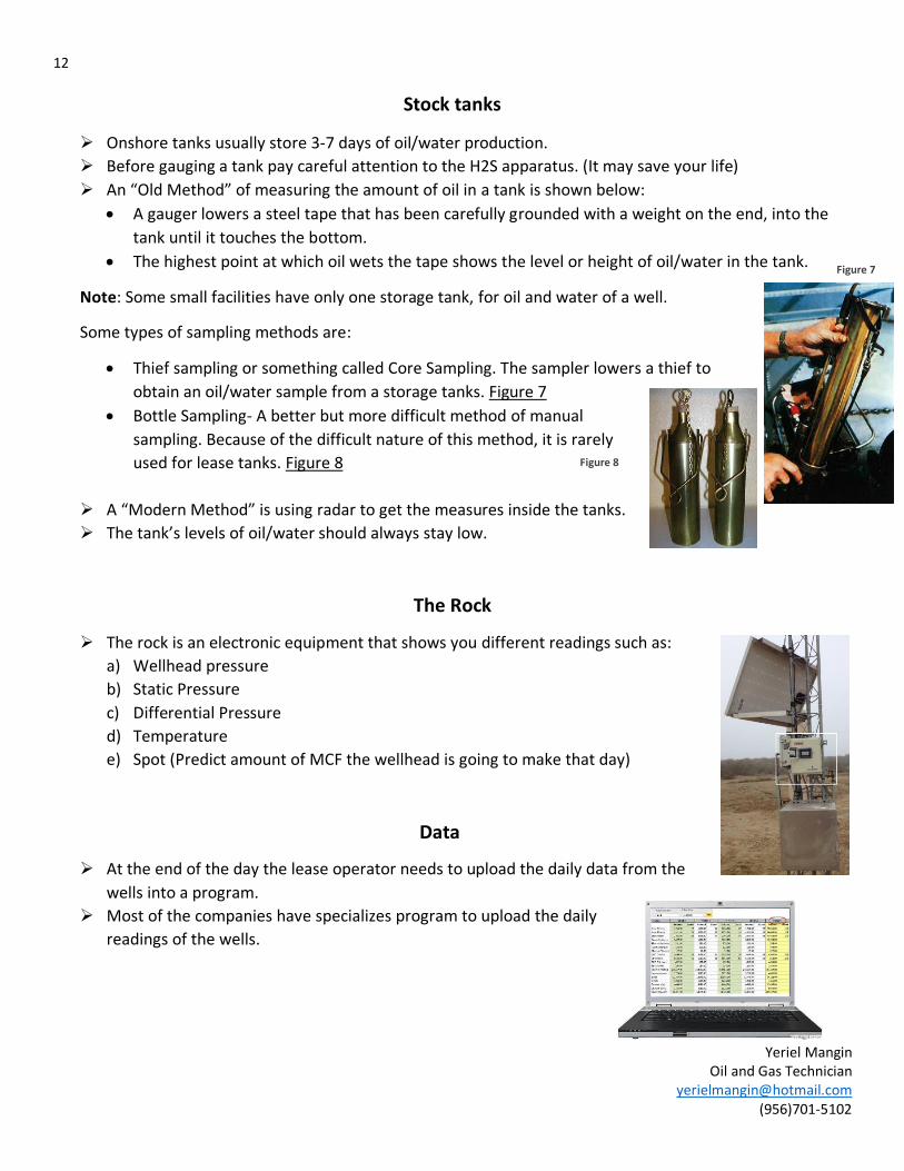
Clean facility
Keeping clean all the wellheads, heaters, separators, tanks, etc. is a vital thing do.
There should not be any grass/weed near the equipment. (Use a shovel to cut off or weed killer spray)
There should not be any tools left out. (Wrench, screws, metal pipes, etc.)
KEEP IT CLEAN!!!
12
Yeriel Mangin Oil and Gas Technician
[email protected] (956)701-5102
Stock tanks
Onshore tanks usually store 3-7 days of oil/water production.
Before gauging a tank pay careful attention to the H2S apparatus. (It may save your life)
An “Old Method” of measuring the amount of oil in a tank is shown below:
A gauger lowers a steel tape that has been carefully grounded with a weight on the end, into the
tank until it touches the bottom.
The highest point at which oil wets the tape shows the level or height of oil/water in the tank.
Note: Some small facilities have only one storage tank, for oil and water of a well.
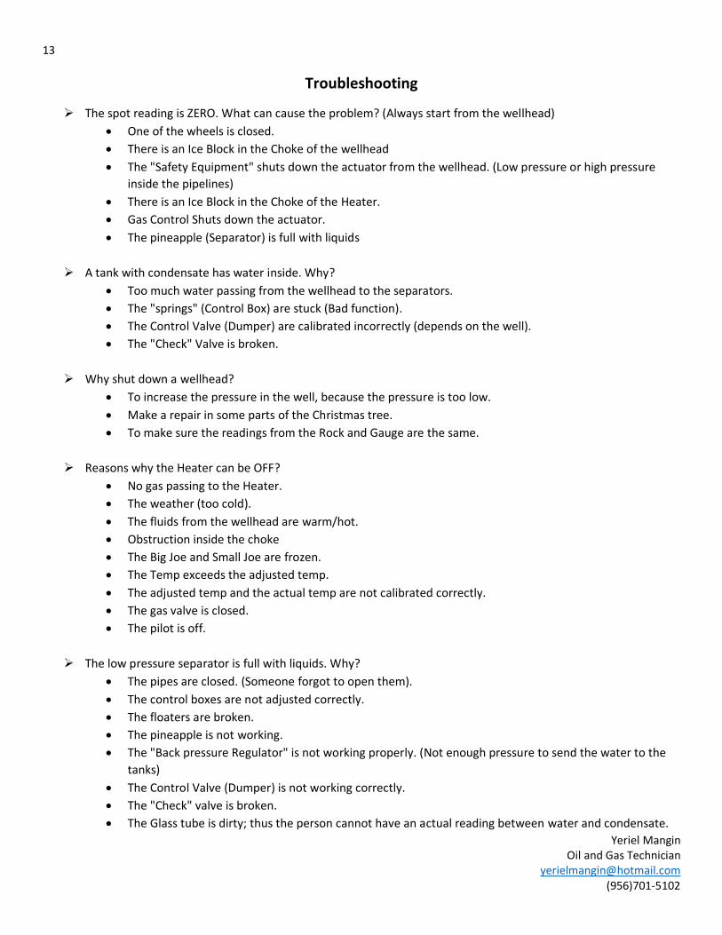
Some types of sampling methods are:
Thief sampling or something called Core Sampling. The sampler lowers a thief to
obtain an oil/water sample from a storage tanks. Figure 7
Bottle Sampling- A better but more difficult method of manual
sampling. Because of the difficult nature of this method, it is rarely
used for lease tanks. Figure 8
A “Modern Method” is using radar to get the measures inside the tanks.
The tank’s levels of oil/water should always stay low.
The Rock
The rock is an electronic equipment that shows you different readings such as:
a) Wellhead pressure
b) Static Pressure
c) Differential Pressure
d) Temperature
e) Spot (Predict amount of MCF the wellhead is going to make that day)
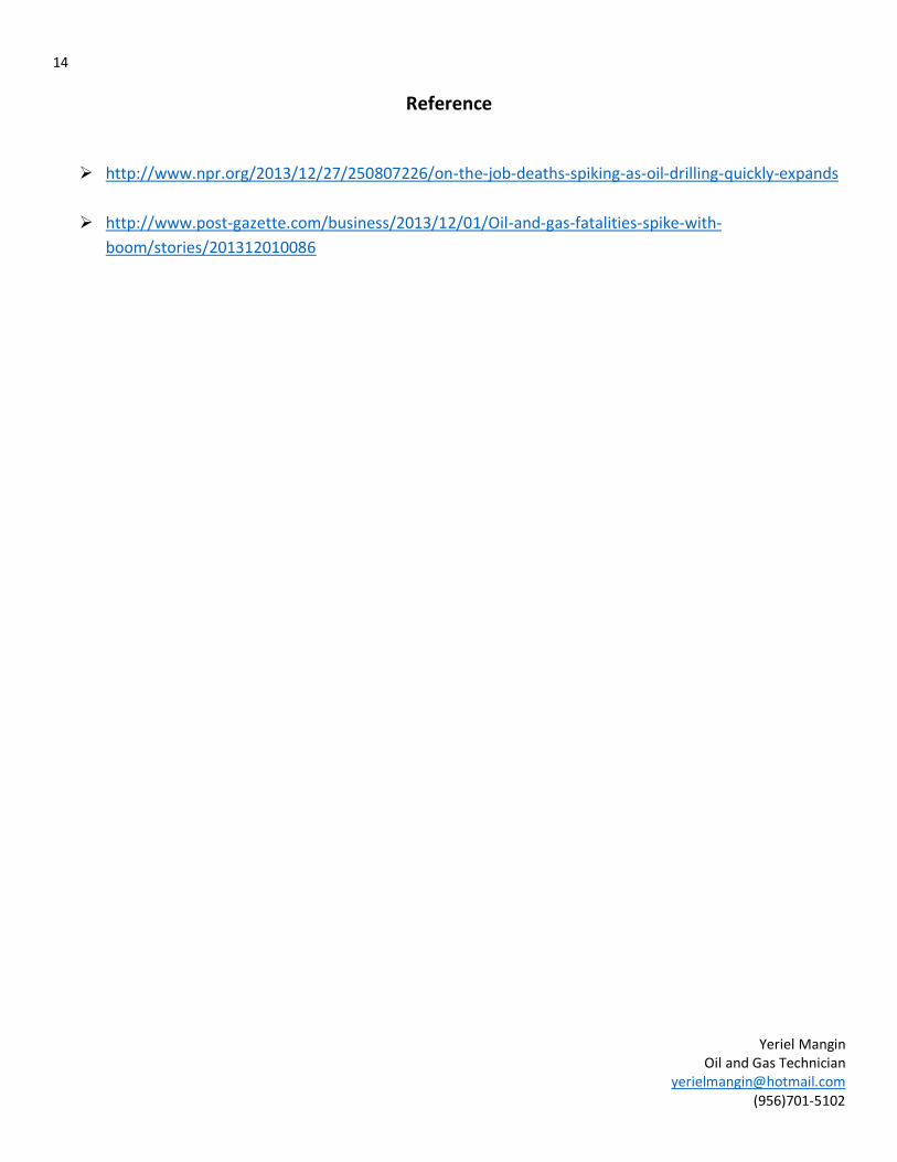
Data
At the end of the day the lease operator needs to upload the daily data from the
wells into a program.
Most of the companies have specializes program to upload the daily
readings of the wells.
Figure 7
Figure 8
13
Yeriel Mangin Oil and Gas Technician
[email protected] (956)701-5102
Troubleshooting
The spot reading is ZERO. What can cause the problem? (Always start from the wellhead)
One of the wheels is closed.
There is an Ice Block in the Choke of the wellhead
The "Safety Equipment" shuts down the actuator from the wellhead. (Low pressure or high pressure
inside the pipelines)
There is an Ice Block in the Choke of the Heater.
Gas Control Shuts down the actuator.
The pineapple (Separator) is full with liquids
A tank with condensate has water inside. Why?
Too much water passing from the wellhead to the separators.
The "springs" (Control Box) are stuck (Bad function).
The Control Valve (Dumper) are calibrated incorrectly (depends on the well).
The "Check" Valve is broken.
Why shut down a wellhead?
To increase the pressure in the well, because the pressure is too low.
Make a repair in some parts of the Christmas tree.
To make sure the readings from the Rock and Gauge are the same.
Reasons why the Heater can be OFF?
No gas passing to the Heater.
The weather (too cold).
The fluids from the wellhead are warm/hot.
Obstruction inside the choke
The Big Joe and Small Joe are frozen.
The Temp exceeds the adjusted temp.
The adjusted temp and the actual temp are not calibrated correctly.
The gas valve is closed.
The pilot is off.
The low pressure separator is full with liquids. Why?
The pipes are closed. (Someone forgot to open them).
The control boxes are not adjusted correctly.
The floaters are broken.
The pineapple is not working.
The "Back pressure Regulator" is not working properly. (Not enough pressure to send the water to the
tanks)
The Control Valve (Dumper) is not working correctly.
The "Check" valve is broken.
The Glass tube is dirty; thus the person cannot have an actual reading between water and condensate.
14
Yeriel Mangin Oil and Gas Technician
[email protected] (956)701-5102
Reference
http://www.npr.org/2013/12/27/250807226/on-the-job-deaths-spiking-as-oil-drilling-quickly-expands
http://www.post-gazette.com/business/2013/12/01/Oil-and-gas-fatalities-spike-with-
boom/stories/201312010086
Recommended