삼 흥정 판
MICROWAVE OVENSERVICE MANUALMODEL: LMV2031ST
LMV2031SBLMV2031SWLMV2031BD
CAUTIONBEFORE SERVICING THE UNIT, READ THE SAFETY PRECAUTIONS IN THIS MANUAL.
P/NO : MFL06272533January, 2014
Printed in Korea
삼 흥정 판
Internal Use Only
-2-
CAUTIONWARNING TO SERVICE TECHNICIANS
PRECAUTIONS TO BE OBSERVED BEFORE ANDDURING SERVICING TO AVOID POSSIBLE EXPOSURE
TO EXCESSIVE MICROWAVE ENERGY
a. Do not operate or allow the oven to be operated with the door open.
b. Make the following safety checks on all ovens to be serviced before activating themagnetron or other microwave source, and make repairs as necessary; (1) Interlockoperation, (2) proper door closing, (3) seal and sealing surfaces (arcing, wear, andother damage), (4) damage to or loosening of hinges and latches, (5) evidence ofdropping or abuse.
c. Before turning on microwave power for any service test or inspection within themicrowave generating compartments, check the magnetron, wave guide ortransmission line, and cavity for proper alignment, integrity, and connections.
d. Any defective or misadjusted components in the interlock, monitor, door seal, andmicrowave generation and transmission systems shall be repaired, replaced, oradjusted by procedures described in this manual before the oven is released to theowner.
e. A microwave leakage check to verify compliance with the federal performancestandard should be performed on each oven prior to release to the owner.
• Proper operation of the microwave oven requires that the magnetron be assembled to the wave guide andcavity. Never operate the magnetron unless it is properly installed.
• Be sure that the magnetron gasket is properly installed around the dome of the tube whenever installing themagnetron.
• Routine service safety procedures should be exercised at all times.
• Untrained personnel should not attempt service without a thorough review of the test procedures and safetyinformation contained in this manual.
FOREWORDRead this manual carefully. Failure to adhere to or observe the information in this manual may result in exposingyourself to the microwave energy normally contained within the oven cavity.
CONTENTS
(Page)
Safety Precautions .............................................................................................................................................. 2
1. Specifications .................................................................................................................................................. 4
2. Cautions ........................................................................................................................................................... 5
3. Installation ....................................................................................................................................................... 6
4. Operation ......................................................................................................................................................... 7
4-1. Control Panel Features .............................................................................................................................. 7
4-2. Explanation of Control Panel...................................................................................................................... 8
5. Wiring Diagram / Key Matrix........................................................................................................................... 9
5-1. Wiring Diagram .......................................................................................................................................... 9
5-2. Key Matrix ............................................................................................................................................... 10
6. Troubleshooting ............................................................................................................................................ 11
6-1. General Information for Service ............................................................................................................... 11
6-2. Safety Caution.......................................................................................................................................... 12
6-3. Basic Check Summary............................................................................................................................. 13
6-4. Troubleshooting ....................................................................................................................................... 14
7. Microwave Leakage Test .............................................................................................................................. 24
8. Power Output Measurement......................................................................................................................... 26
9. Interlock System............................................................................................................................................ 27
9-1. Interlock Mechanism ................................................................................................................................ 27
9-2. Interlock Continuity Test........................................................................................................................... 29
10. Component Testing Information................................................................................................................ 30
11. Disassembly Instructions........................................................................................................................... 34
12. Exploded View ............................................................................................................................................. 40
-3-
-4-
1. SPECIFICATIONS
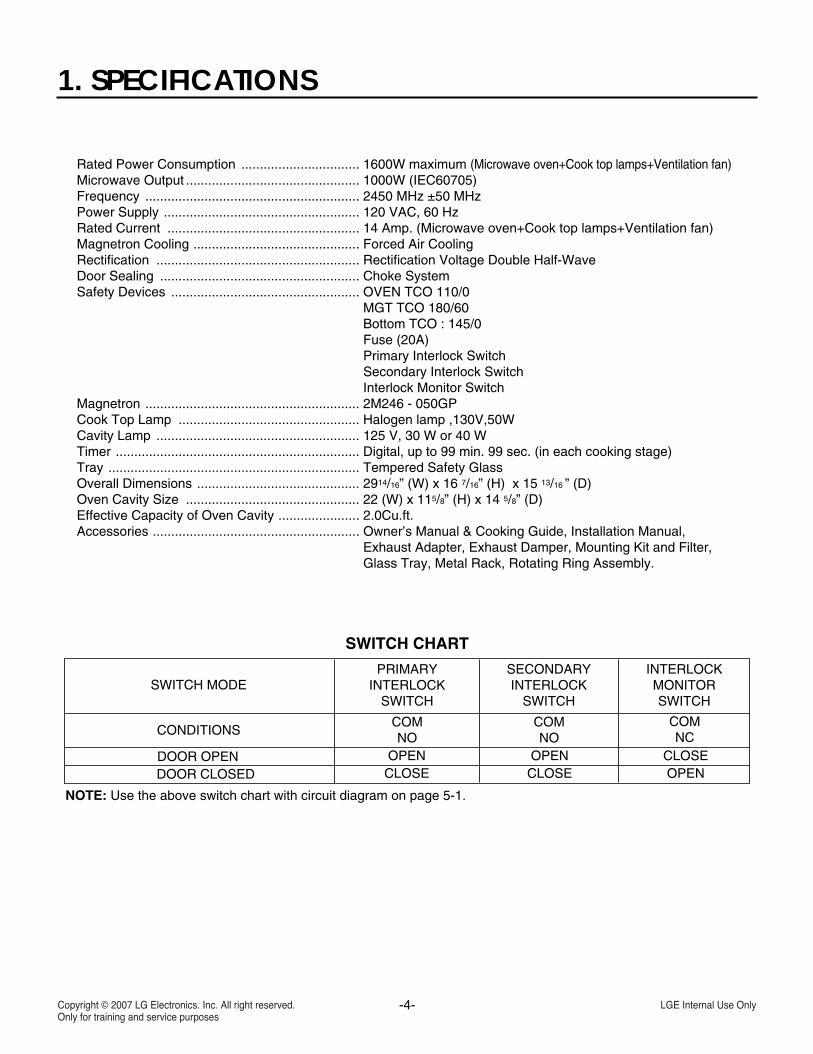
Rated Power Consumption ................................ 1600W maximum (Microwave oven+Cook top lamps+Ventilation fan)Microwave Output ............................................... 1000W (IEC60705)Frequency .......................................................... 2450 MHz ±50 MHzPower Supply ..................................................... 120 VAC, 60 HzRated Current .................................................... 14 Amp. (Microwave oven+Cook top lamps+Ventilation fan)Magnetron Cooling ............................................. Forced Air CoolingRectification ....................................................... Rectification Voltage Double Half-WaveDoor Sealing ...................................................... Choke SystemSafety Devices ................................................... OVEN TCO 110/0............................................................................ MGT TCO 180/60............................................................................ Bottom TCO : 145/0............................................................................ Fuse (20A)............................................................................ Primary Interlock Switch............................................................................ Secondary Interlock Switch............................................................................ Interlock Monitor SwitchMagnetron .......................................................... 2M246 - 050GPCook Top Lamp ................................................. Halogen lamp ,130V,50WCavity Lamp ....................................................... 125 V, 30 W or 40 WTimer .................................................................. Digital, up to 99 min. 99 sec. (in each cooking stage)Tray .................................................................... Tempered Safety GlassOverall Dimensions ............................................ 2914/16” (W) x 16 7/16” (H) x 15 13/16 ” (D)Oven Cavity Size ............................................... 22 (W) x 115/8” (H) x 14 5/8” (D)Effective Capacity of Oven Cavity ...................... 2.0Cu.ft.Accessories ........................................................ Owner’s Manual & Cooking Guide, Installation Manual,............................................................................ Exhaust Adapter, Exhaust Damper, Mounting Kit and Filter,............................................................................ Glass Tray, Metal Rack, Rotating Ring Assembly.
SWITCH CHART
SWITCH MODE
CONDITIONS
DOOR OPEN OPEN OPEN CLOSECLOSE CLOSE OPENDOOR CLOSED
PRIMARYINTERLOCK
SWITCH
SECONDARYINTERLOCK
SWITCH
INTERLOCKMONITORSWITCH
COMNO
COMNO
COMNC
NOTE: Use the above switch chart with circuit diagram on page 5-1.
-5-
2. CAUTIONS
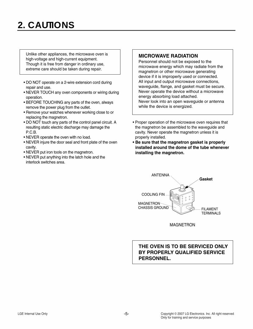
Unlike other appliances, the microwave oven ishigh-voltage and high-current equipment.Though it is free from danger in ordinary use,extreme care should be taken during repair.
MICROWAVE RADIATIONPersonnel should not be exposed to themicrowave energy which may radiate from themagnetron or other microwave generatingdevice if it is improperly used or connected.All input and output microwave connections,waveguide, flange, and gasket must be secure.Never operate the device without a microwaveenergy absorbing load attached.Never look into an open waveguide or antennawhile the device is energized.
• DO NOT operate on a 2-wire extension cord duringrepair and use.
• NEVER TOUCH any oven components or wiring duringoperation.
• BEFORE TOUCHING any parts of the oven, alwaysremove the power plug from the outlet.
• Remove your watches whenever working close to orreplacing the magnetron.
• DO NOT touch any parts of the control panel circuit. Aresulting static electric discharge may damage theP.C.B.
• NEVER operate the oven with no load.• NEVER injure the door seal and front plate of the oven
cavity.• NEVER put iron tools on the magnetron.• NEVER put anything into the latch hole and the
interlock switches area.
• Proper operation of the microwave oven requires thatthe magnetron be assembled to the waveguide andcavity. Never operate the magnetron unless it is properly installed.
• Be sure that the magnetron gasket is properly installed around the dome of the tube wheneverinstalling the magnetron.
THE OVEN IS TO BE SERVICED ONLYBY PROPERLY QUALIFIED SERVICEPERSONNEL.
GasketANTENNA
COOLING FIN
MAGNETRONCHASSIS GROUND FILAMENT
TERMINALS
MAGNETRON
-6-
3. INSTALLATION
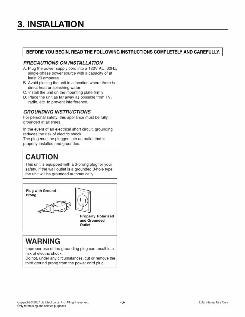
BEFORE YOU BEGIN, READ THE FOLLOWING INSTRUCTIONS COMPLETELY AND CAREFULLY.
PRECAUTIONS ON INSTALLATIONA. Plug the power supply cord into a 120V AC, 60Hz,
single-phase power source with a capacity of atleast 20 amperes.
B. Avoid placing the unit in a location where there isdirect heat or splashing water.
C. Install the unit on the mounting plate firmly.D. Place the unit as far away as possible from TV,
radio, etc. to prevent interference.
GROUNDING INSTRUCTIONSFor personal safety, this appliance must be fullygrounded at all times.
In the event of an electrical short circuit, groundingreduces the risk of electric shock.The plug must be plugged into an outlet that isproperly installed and grounded.
CAUTIONThis unit is equipped with a 3-prong plug for yoursafety. If the wall outlet is a grounded 3-hole type,the unit will be grounded automatically.
WARNINGImproper use of the grounding plug can result in arisk of electric shock.Do not, under any circumstances, cut or remove thethird ground prong from the power cord plug.
-7-
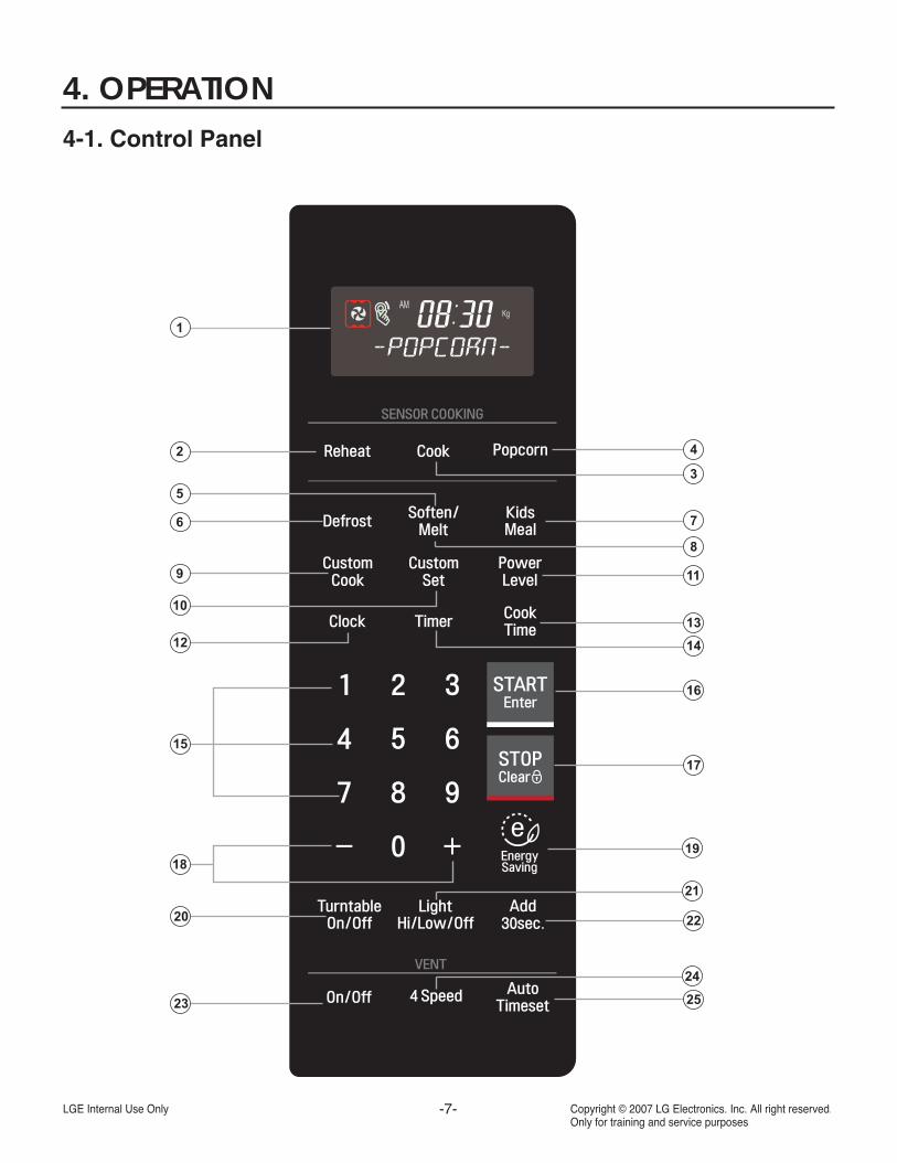
4. OPERATION4-1. Control Panel
2
1
9
12
10
20
23
18
6
5
4
11
21
24
25
16
7
8
15
19
14
13
17
22
3
-8-
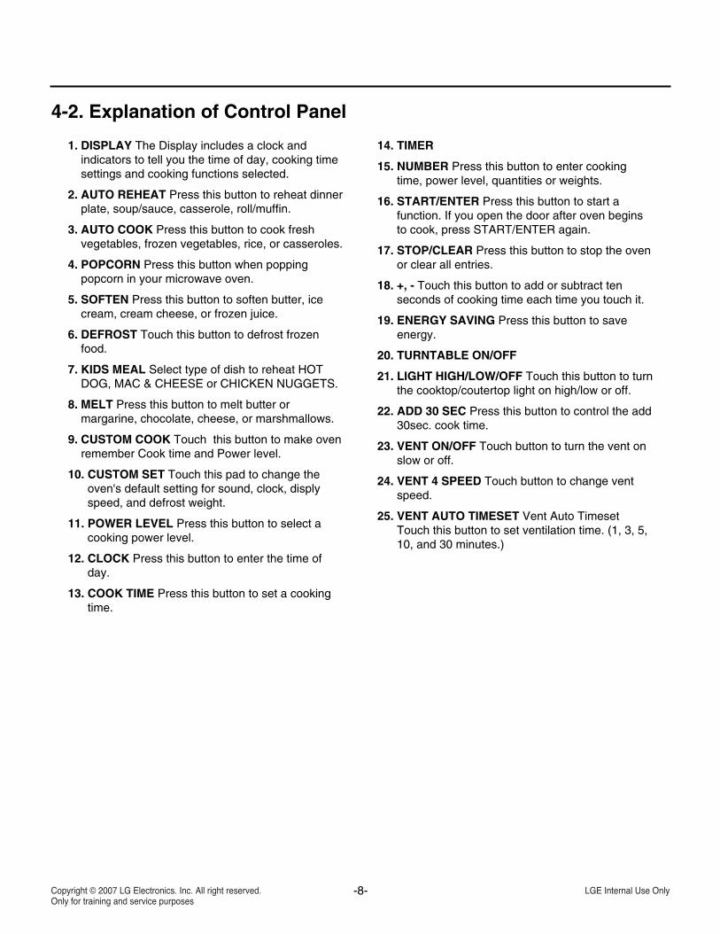
4-2. Explanation of Control Panel
1. DISPLAY The Display includes a clock andindicators to tell you the time of day, cooking timesettings and cooking functions selected.
2. AUTO REHEAT Press this button to reheat dinnerplate, soup/sauce, casserole, roll/muffin.
3. AUTO COOK Press this button to cook freshvegetables, frozen vegetables, rice, or casseroles.
4. POPCORN Press this button when poppingpopcorn in your microwave oven.
5. SOFTEN Press this button to soften butter, icecream, cream cheese, or frozen juice.
6. DEFROST Touch this button to defrost frozenfood.
7. KIDS MEAL Select type of dish to reheat HOTDOG, MAC & CHEESE or CHICKEN NUGGETS.
8. MELT Press this button to melt butter ormargarine, chocolate, cheese, or marshmallows.
9. CUSTOM COOK Touch this button to make ovenremember Cook time and Power level.
10. CUSTOM SET Touch this pad to change theoven's default setting for sound, clock, displyspeed, and defrost weight.
11. POWER LEVEL Press this button to select acooking power level.
12. CLOCK Press this button to enter the time ofday.
13. COOK TIME Press this button to set a cookingtime.
14. TIMER
15. NUMBER Press this button to enter cookingtime, power level, quantities or weights.
16. START/ENTER Press this button to start afunction. If you open the door after oven beginsto cook, press START/ENTER again.
17. STOP/CLEAR Press this button to stop the ovenor clear all entries.
18. +, - Touch this button to add or subtract tenseconds of cooking time each time you touch it.
19. ENERGY SAVING Press this button to saveenergy.
20. TURNTABLE ON/OFF
21. LIGHT HIGH/LOW/OFF Touch this button to turnthe cooktop/coutertop light on high/low or off.
22. ADD 30 SEC Press this button to control the add30sec. cook time.
23. VENT ON/OFF Touch button to turn the vent onslow or off.
24. VENT 4 SPEED Touch button to change ventspeed.
25. VENT AUTO TIMESET Vent Auto TimesetTouch this button to set ventilation time. (1, 3, 5,10, and 30 minutes.)
-9-
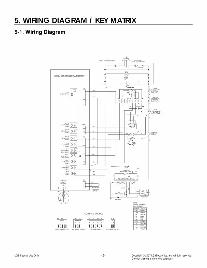
5. WIRING DIAGRAM / KEY MATRIX 5-1. Wiring Diagram
OGVL VIOLET
ORANGE
YLPKPK GY BLRD WH
BK
C. L.
RD
BNYL
YL
21VAC
CAPACITOR
PK
WH
BN
GY
WH
RD
WH
RD
BNYL
180 60356 140
WH
WH
YL
PK
YL
WOL
HGI
H
OB
RU
T
VL
12345678
SLO
W
WHOGYL
BL
7
10
RDBN
BK
BL
12345678
WHWH
8
3
HW
WH
HW
H.V.FUSE
-10-
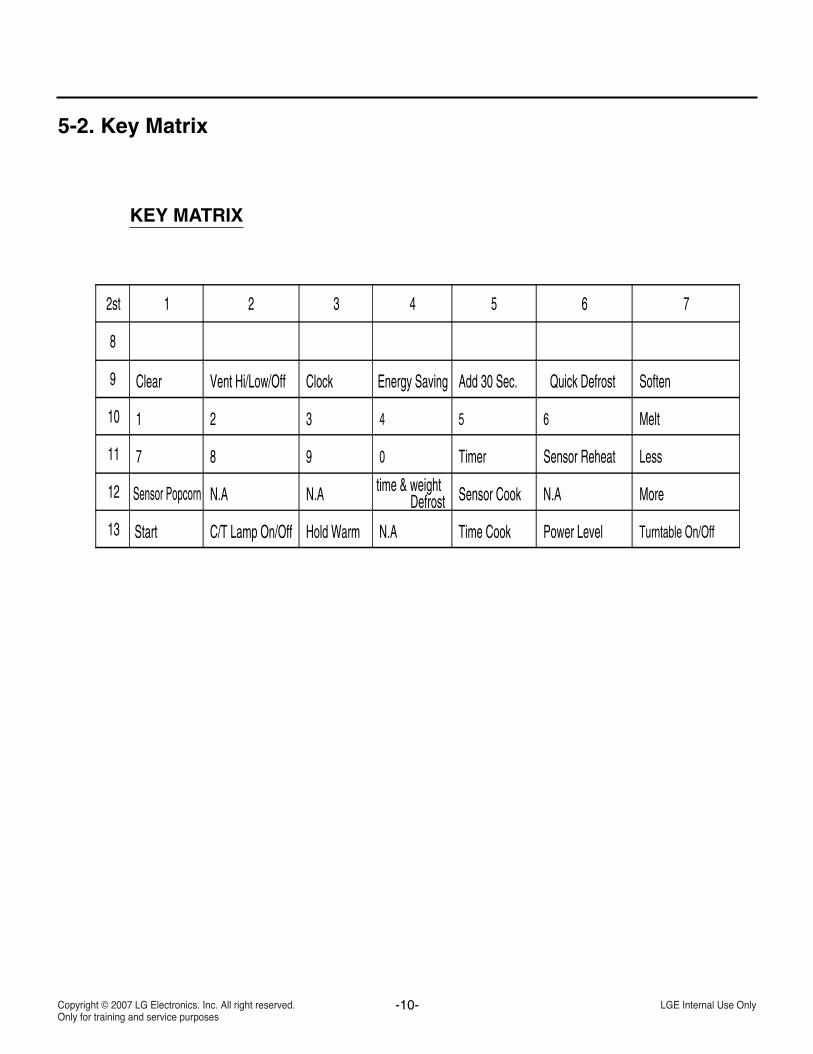
5-2. Key Matrix
Turntable On/OffPower LevelTime CookHold WarmC/T Lamp On/OffStart13
MoreSensor Cooktime & weightDefrostN.A N.A
N.A
N.ASensor Popcorn12
LessSensor ReheatTimer098711
Melt65432110
SoftenQuick DefrostAdd 30 Sec.Energy SavingClockVent Hi/Low/OffClear9
8
76543212st
KEY MATRIX
-11-
6. TROUBLESHOOTING 6-1. General Information for Service
GENERAL PRECAUTIONS IN USE
A. Never operate the unit when it is empty. Operating the oven with no load may shorten thelife of the magnetron. Whenever cooking dryfoods (dried fish, bread, etc.)or a small amount offood, be sure to put a glass of water into thecooking compartment. The glass turntable maybecome hot after operating, be careful whentouching it.
B. Aluminum foil should be avoided because it willdisrupt cooking and may cause arcing. However,small pieces may be used to cover some parts offood to slow the cooking. Any aluminum foil usedshould never be closer than 1 in. (2.5 cm) to anyside wall of the oven.
TRIAL OPERATIONAfter installation, the following sequences andresults should be checked carefully.
A. Put a container filled with water (about 1 liter) intothe oven, and close the door tightly.
B. Set cooking time for 10 minutes by touching 1 andthen 0 three times. 1, 0, 0, 0 appears in thedisplay window.
C. Press the START button Make sure the cavity light comes on. The unit willbegin cooking and the display window will showthe time counting down by seconds.
D. After about 5 minutes, make sure the primaryinterlock switch, the secondary interlock switchand the interlock monitor switch operate properlyby opening and closing the door several times.Press the START button each time the door isclosed.
E. Continue operating the unit. Two short beeps andone long beep will sound when the time is up.The unit will shut off automatically.
F. Confirm the water is hot. G. Finally, measure the output power according to
the POWER OUTPUT MEASUREMENT on page 8.
FEATURES AND SPECIFICATIONSFEATURESA. The safety systems incorporated in this modelare:
(1) Primary interlock switch(2) Secondary interlock switch(3) Interlock monitor switch(4) Choke system(5) Oven cavity thermostat
(Note This thermostat located on the ovencavity will open and stop the unit fromoperation only if a high temperature isreached, such as, a fire created byovercooking food.)
B. Any one of 10 power output levels ranging 0 W to1,000 W can be selected by the touch control andelectronic computer system.
C. Cooking time can be displayed on the digitalreadout.
D. Three different cooking stages (including defrost)can proceed from one cooking stage to another.This is made possible with the memory function ofthe microprocessor.
-12-
A. SINCE NEARLY 4,000 VOLTS EXISTS INSOME CIRCUITS OF THIS UNIT REPAIRSSHOULD BE CARRIED OUT WITH GREATCARE.The filament leads of the magnetron carry HighVoltage with respect to the ground. Extremecaution must be exercised. Never plug the unitinto a power source to determine whichcomponent is defective in the high voltagesection.
B. TO AVOID POSSIBLE EXPOSURE TOMICROWAVE ENERGY LEAKAGE, THEFOLLOWING PRECAUTIONS MUST BETAKEN BEFORE SERVICING.
(1) Before the power is applied:(a) Make sure the primary interlock switch, the
secondary interlock switch and the interlockmonitor switch operate properly by openingand closing the door several times.
(b) Make sure the perforated screen and thedielectric choke of the door are correctly andfirmly mounted.
(2) After power is applied:(a) Make sure the interlock switch mechanism
is operating properly by opening and closingthe door.
(b) Check microwave energy leakage must bebelow the limit of 5 mW/cm2 .(All service adjustments should be made forminimum microwave energy leakagereadings).
(3) Do not operate the unit until it is completelyrepaired. If any of the following conditions exist,the unit must not be operated.
(a) The door does not close firmly.(b) The hinge is broken.(c) The door seal is damaged.(d) The door is bent or warped, or there is any
other visible damage on the unit that maycause microwave energy leakage.
NOTE: Always keep the seal clean.(e) Make sure that there are no defective parts
in the interlock mechanism.(f) Make sure that there are no detective parts
in the microwave generating andtransmission assembly (especiallywaveguide).
(4) The following items should be checked after theunit is repaired:
(a) The interlock monitor switch is connectedcorrectly and firmly.
(b) The magnetron gasket is properly positionedand mounted.
(c) The waveguide and the oven cavity areintact. (no microwave energy leakage)
(d) The door can be properly closed and thesafety switches work properly.
(e) The unit must stop when the door is openedor the time is up.
The unit must not be operated with any of the abovecomponents removed or bypassed.
1.Press “Defrost weight/time” for 2 seconds , unit willdisplay “TEST” and Beep once;
2.The unit will check if the PCB humidity sensor andPCB thermistor are short or open.
3.If it has an error, it will beep and display an errorcode.
4.If the unit is normal , it will beep and display"PASS".
5.Press “ Clear” to return to Standby mode.
6-2. Safety Caution
6-3 Self diagnosis (humidity Sensor and PCB thermistor check) &Error code
Error code
F-1
F-2
F-4
Symptom
PCB thermistor short
PCB thermistor open
Humidity sensor open or short
-13-
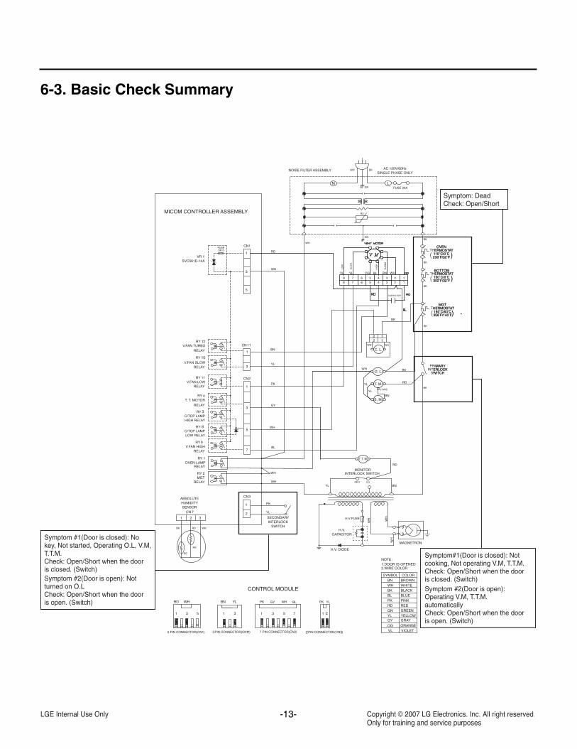
6-3. Basic Check Summary
OGVL VIOLET
ORANGE
YLPKPK GY BLRD WH
BK
C. L.
RD
BNYL
YL
21VAC
CAPACITOR
PK
WH
BN
GY
WH
RD
WH
RD
BNYL
180 60356 140
WH
WH
YL
PK
YL
WOL
HGI
H
OB
RU
T
VL
12345678
SLO
W
WHOGYL
BL
7
10
RDBN
BK
BL
12345678
WHWH
8
3
HW
WH
HW
H.V.FUSE
Symptom: DeadCheck: Open/Short
Symptom#1(Door is closed): Not cooking, Not operating V.M, T.T.M. Check: Open/Short when the door is closed. (Switch)Symptom #2(Door is open): Operating V.M, T.T.M. automaticallyCheck: Open/Short when the door is open. (Switch)
Symptom #1(Door is closed): No key, Not started, Operating O.L, V.M, T.T.M. Check: Open/Short when the door is closed. (Switch)Symptom #2(Door is open): Not turned on O.LCheck: Open/Short when the door is open. (Switch)
180 60356 140
-14-
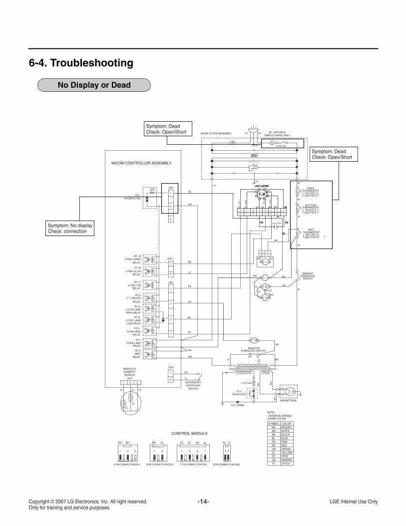
6-4. Troubleshooting
No Display or Dead
Symptom: DeadCheck: Open/Short
Symptom: DeadCheck: Open/Short
Symptom: No displayCheck: connection
OGVL VIOLET
ORANGE
YLPKPK GY BLRD WH
BK
C. L.
RD
BNYL
YL
21VAC
CAPACITOR
PK
WH
BN
GY
WH
RD
WH
RD
BNYL
180 60356 140
WH
WH
YL
PK
YL
WOL
HGI
H
OB
RU
T
VL
12345678
SLO
W
WHOGYL
BL
7
10
RDBN
BK
BL
12345678
WHWH
8
3
HW
WH
HW
H.V.FUSE
-15-
6
3
4
LLLLLLLLLLLLLLLLLLLLLLNNNNNNNNNNNNNNNNNNNNNN
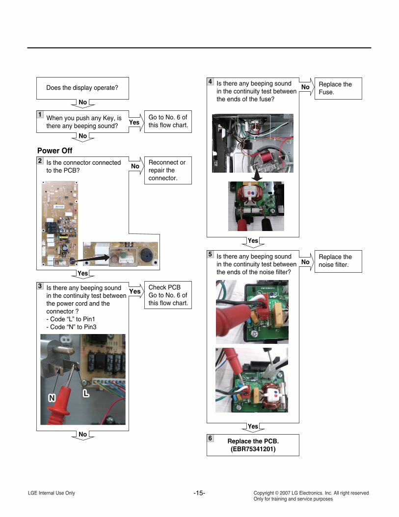
1 When you push any Key, isthere any beeping sound?
Does the display operate?
No
No
Yes
2 Is the connector connectedto the PCB?
Power Off
Yes
No Reconnect orrepair theconnector.
Is there any beeping soundin the continuity test betweenthe power cord and theconnector ?- Code “L” to Pin1- Code “N” to Pin3
No
YesCheck PCBGo to No. 6 ofthis flow chart.
Go to No. 6 ofthis flow chart.
Is there any beeping soundin the continuity test betweenthe ends of the fuse?
Yes
No Replace theFuse.
5 Is there any beeping soundin the continuity test betweenthe ends of the noise filter?
Yes
NoReplace thenoise filter.
Replace the PCB.(EBR75341201)
-16-
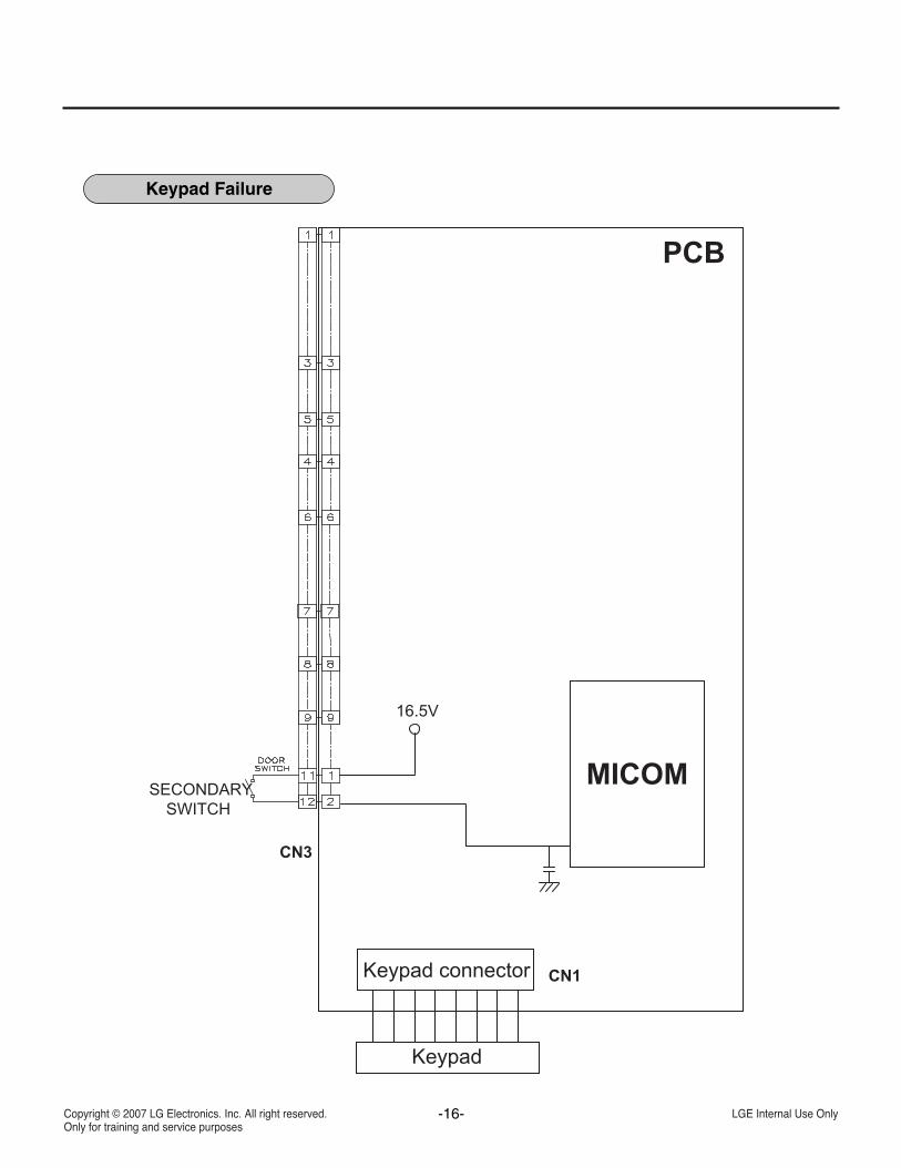
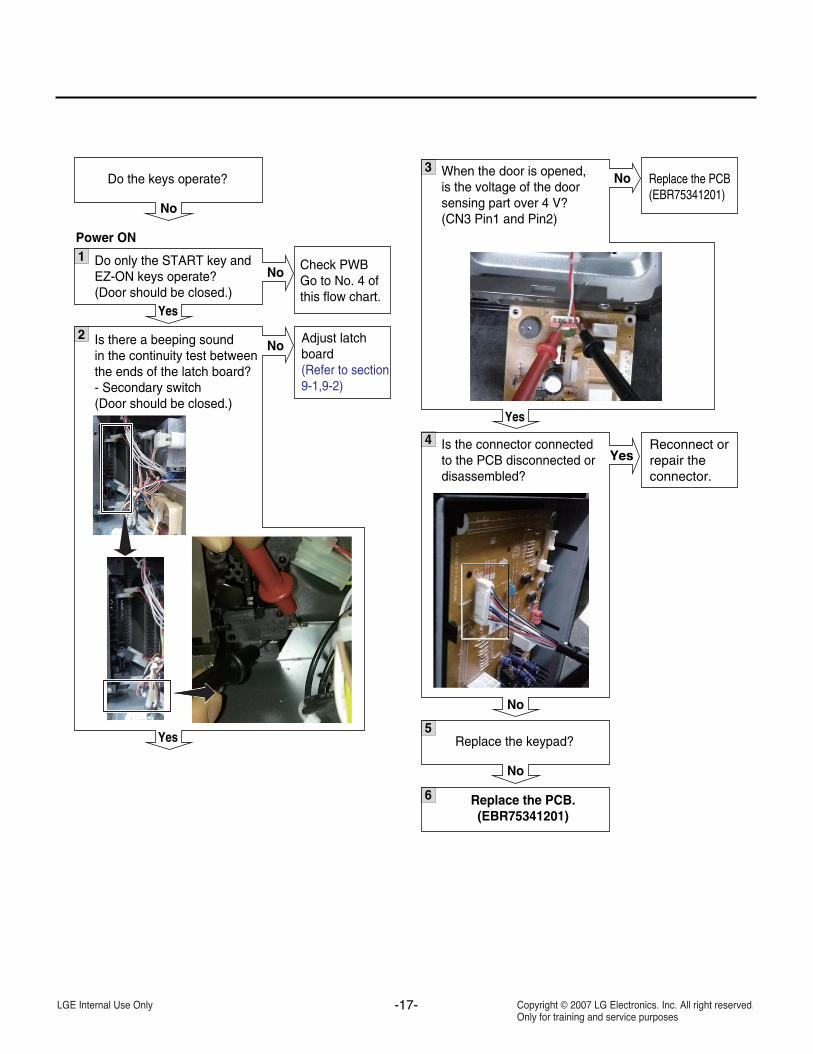
Keypad Failure
-17-
5
6
1 Do only the START key andEZ-ON keys operate?(Door should be closed.)
Do the keys operate?
No
Yes
No
2 Is there a beeping soundin the continuity test betweenthe ends of the latch board?- Secondary switch(Door should be closed.)
Power ON
Yes
No Adjust latch board(Refer to section9-1,9-2)
Check PWB Go to No. 4 ofthis flow chart.
3 When the door is opened,is the voltage of the doorsensing part over 4 V?(CN3 Pin1 and Pin2)
Yes
No Replace the PCB(EBR75341201)
Reconnect orrepair theconnector.
Replace the PCB.(EBR75341201)
4 Is the connector connectedto the PCB disconnected ordisassembled?
No
Yes
Replace the keypad?
No
-18-
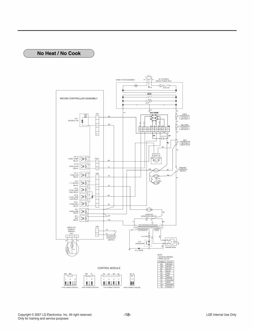
No Heat / No Cook
OGVL VIOLET
ORANGE
YLPKPK GY BLRD WH
BK
C. L.
RD
BNYL
YL
21VAC
CAPACITOR
PK
WH
BN
GY
WH
RD
WH
RD
BNYL
180 60356 140
WH
WH
YL
PK
YL
WOL
HGI
H
OB
RU
T
VL
12345678
SLO
W
WHOGYL
BL
7
10
RDBN
BK
BL
12345678
WHWH
8
3
HW
WH
HW
H.V.FUSE
-19-
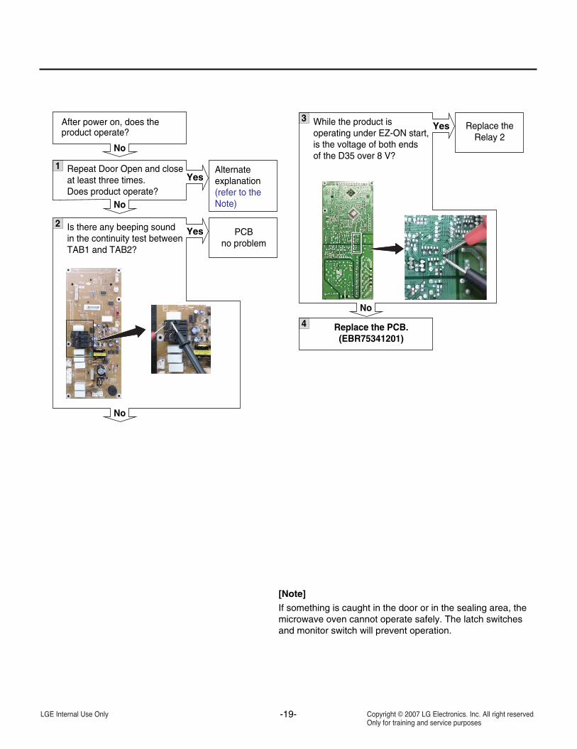
1 Repeat Door Open and closeat least three times.Does product operate?
After power on, does theproduct operate?
No
No
Yes
2 Is there any beeping soundin the continuity test betweenTAB1 and TAB2?
No
Yes PCBno problem
Alternateexplanation(refer to theNote)
3 While the product is operating under EZ-ON start,is the voltage of both endsof the D35 over 8 V?
No
Yes Replace theRelay 2
4 Replace the PCB.(EBR75341201)
[Note]If something is caught in the door or in the sealing area, themicrowave oven cannot operate safely. The latch switchesand monitor switch will prevent operation.
-20-
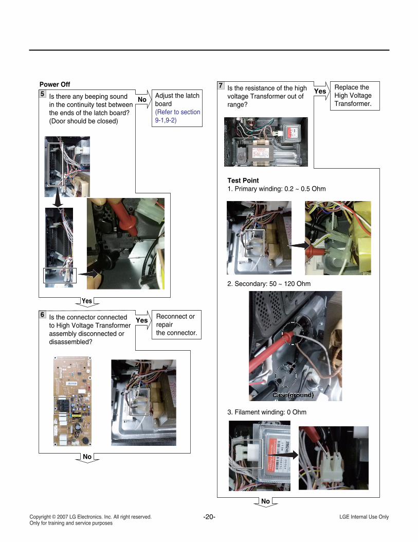
5 Is there any beeping sound in the continuity test betweenthe ends of the latch board?(Door should be closed)
Power Off
Yes
No Adjust the latch board(Refer to section9-1,9-2)
7 Is the resistance of the highvoltage Transformer out ofrange?
Test Point1. Primary winding: 0.2 ~ 0.5 Ohm
2. Secondary: 50 ~ 120 Ohm
3. Filament winding: 0 Ohm
No
Yes Replace theHigh VoltageTransformer.
6 Is the connector connectedto High Voltage Transformer assembly disconnected or disassembled?
No
Yes Reconnect orrepairthe connector.
-21-
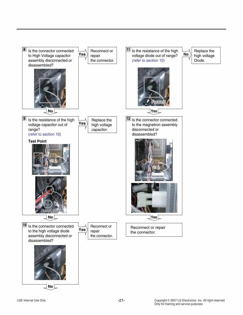
9 Is the resistance of the highvoltage capacitor out ofrange?(refer to section 10)
Test Point
No
YesReplace thehigh voltagecapacitor.
Case(ground)Case(ground)Case(ground)
8 Is the connector connectedto High Voltage capacitor assembly disconnected or disassembled?
No
YesReconnect orrepairthe connector.
Case(ground)
10 Is the connector connectedto the high voltage diode assembly disconnected or disassembled?
No
YesReconnect orrepairthe connector.
Case(ground)
12 Is the connector connected to the magnetron assemblydisconnected or disassembled?
YesCase(ground)
11 Is the resistance of the highvoltage diode out of range?(refer to section 10)
Yes
NoReplace thehigh voltageDiode.
ForwardForwardForwardForwardForwardForwardForwardForwardForwardForwardForwardForwardForwardForwardForwardForwardForwardForwardForwardForwardForwardForward
Case(ground)
Reconnect or repairthe connector.
-22-
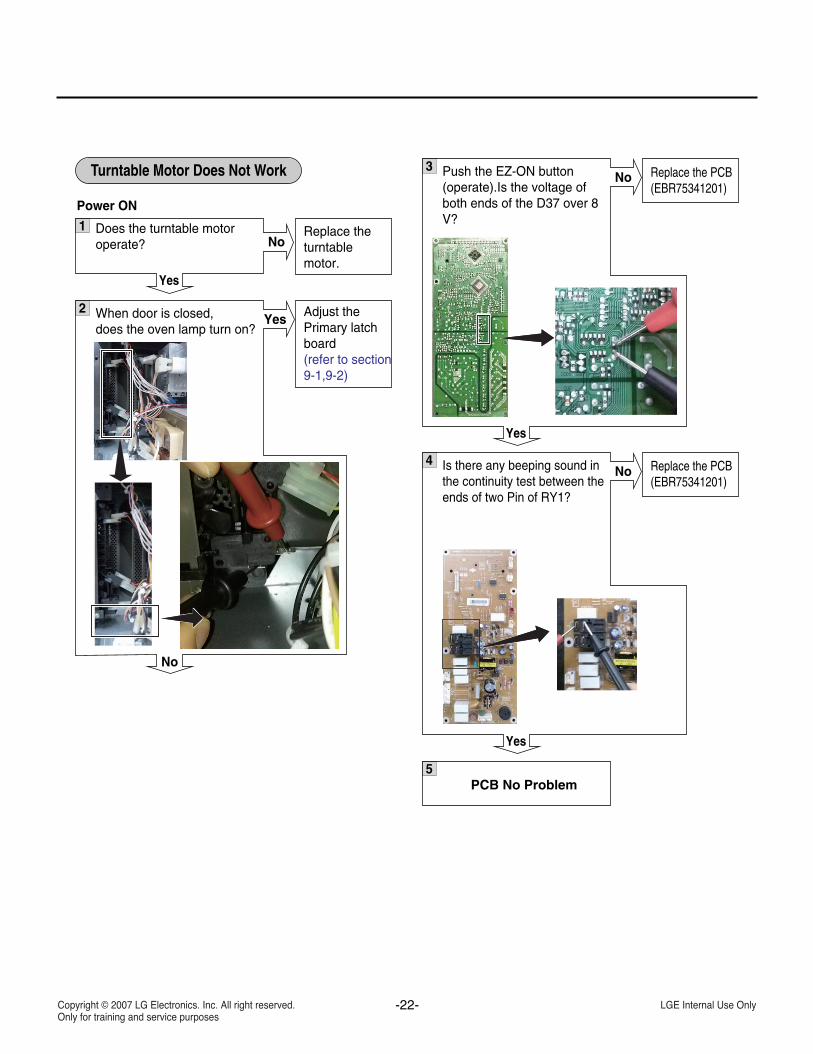
Turntable Motor Does Not Work
1 Does the turntable motoroperate?
Yes
No
2 When door is closed,does the oven lamp turn on?
No
Yes Adjust thePrimary latchboard(refer to section9-1,9-2)
Replace theturntable motor.
Power ON
3 Push the EZ-ON button(operate).Is the voltage ofboth ends of the D37 over 8V?
Yes
No Replace the PCB(EBR75341201)
4 Is there any beeping sound inthe continuity test between theends of two Pin of RY1?
Yes
No Replace the PCB(EBR75341201)
5PCB No Problem
-23-
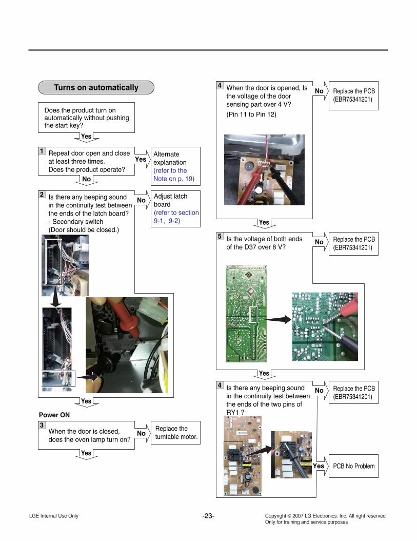
Turns on automatically
1 Repeat door open and closeat least three times.Does the product operate?
Does the product turn onautomatically without pushingthe start key?
Yes
No
YesAlternateexplanation(refer to theNote on p. 19)
3When the door is closed,does the oven lamp turn on?
Yes
NoReplace theturntable motor.
2 Is there any beeping soundin the continuity test betweenthe ends of the latch board?- Secondary switch(Door should be closed.)
Yes
No Adjust latchboard(refer to section9-1, 9-2)
Power ON
4 When the door is opened, Isthe voltage of the doorsensing part over 4 V?
(Pin 11 to Pin 12)
Yes
No Replace the PCB(EBR75341201)
4 Is there any beeping soundin the continuity test betweenthe ends of the two pins ofRY1 ?
No
Yes
5 Is the voltage of both endsof the D37 over 8 V?
Yes
No
Replace the PCB(EBR75341201)
PCB No Problem
Replace the PCB(EBR75341201)
-24-
7. MICROWAVE LEAKAGE TEST CAUTION
• Be sure to check microwave leakage prior toservicing the oven if the oven is operating prior toservicing.
• Service personnel should inform themanufacturer, importer, or assembler of anycertified oven unit found to have a microwaveemission level in excess of 5 mW/cm2 and shouldrepair any unit found to have excessive emissionlevels at no cost to the owner and should ascertain thecause of the excessive leakage. The service personnelshould instruct the owner not to use the unit until theoven has been brought into compliance.
• If the oven operates with the door open, servicepersonnel should;
- Tell the user not to operate the oven- Contact the manufacturer and CDRH (Center for
Devices and Radiological Health)immediately.NOTE: Address to CDRH
Office of Compliance (HFZ-312)Center for Devices and Radiological Health1390 Piccard Drive Rockville, Maryland 20850
• Service personnel should check all surface andvent openings for microwave emission testing.
• Check for microwave energy leakage after everyservicing. The power density of the microwaveradiation leakage emitted by the microwave ovenshould not exceed 1mW/cm2.sq. Always startmeasuring of an unknown field to assure safety foroperating personnel from radiation leakage.NOTE: The standard is 5mW/cm2.sq. while in thecustomer’s home.1mW/cm2.sq.stated here ismanufacturer’s own voluntary standard for units incustomer’s home.
EQUIPMENT-
• TESTER ((VOLTS-DC, AC, Ohmmeter)• Microwave survey meter- Holaday HI-1500
HI-1501- Narda 8100
8200• 600 cc non conductive material beaker (glass or
plastic), inside diameter:approx.8.5 cm (31/2 in.)• Glass thermometer: 100 °C or 212 °F (1 deg scale)
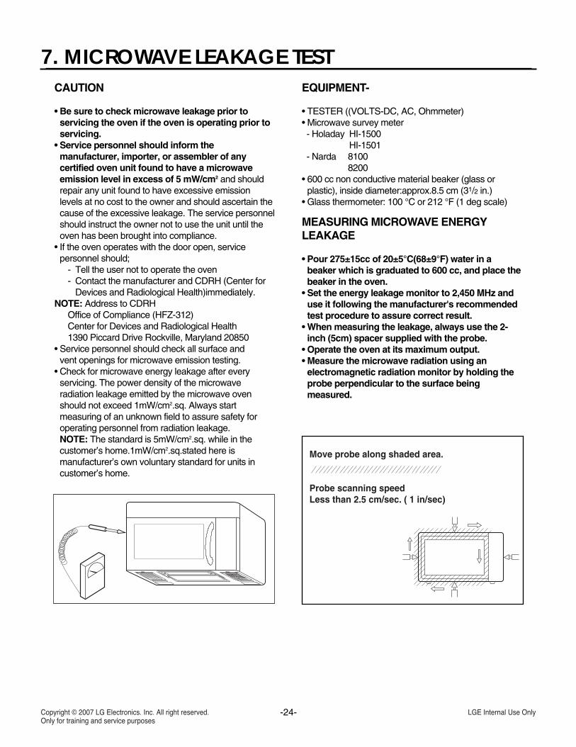
MEASURING MICROWAVE ENERGYLEAKAGE
• Pour 275±15cc of 20±5°C(68±9°F) water in abeaker which is graduated to 600 cc, and place thebeaker in the oven.
• Set the energy leakage monitor to 2,450 MHz anduse it following the manufacturer's recommendedtest procedure to assure correct result.
• When measuring the leakage, always use the 2-inch (5cm) spacer supplied with the probe.
• Operate the oven at its maximum output.• Measure the microwave radiation using an
electromagnetic radiation monitor by holding theprobe perpendicular to the surface beingmeasured.
Move probe along shaded area.
Probe scanning speedLess than 2.5 cm/sec. ( 1 in/sec)
-25-
MEASUREMENT WITH THE OUTERCASEREMOVED(1) When you replace the magnetron, measure for
microwave energy leakage before the outer caseis installed and after all necessary componentsare replaced or adjusted. Special care should betaken in measuring the following parts.-Around the magnetron-The waveguide
WARNING: AVOID CONTACTING ANY HIGHVOLTAGE PARTS.
MEASUREMENT WITH A FULLYASSEMBLED OVEN(1) After all components, including the outer
panels, are fully assembled, measure formicrowave energy leakage around the doorviewing window, the exhaust opening and airinlet openings.
(2) Microwave energy leakage must not exceed thevalues prescribed below. NOTES:Leakage with the outer panels removedthan 5 mW/cm2. Leakage for a fully assembled oven (before thelatch switch [primary] is interrupted) with thedoor in a slightly opened position -less than 1mW/cm2
NOTE WHEN MEASURING(1) Do not exceed meter full scale deflection. (2) The test probe must be removed no faster than
1 inch/sec (2.5cm/sec)along the shaded area,otherwise a false reading may result.
(3) The test probe must be held with the grip portionof the handle. A false reading may result if theoperator ’s hand is between the handle and theprobe.
(4) When testing near a corner of the door, keepthe probe perpendicular to the surface makingsure to move the probe horizontally along theoven surface. Doing so will avoid possibledamage to the probe.
RECORD KEEPING AND NOTIFICATIONAFTER MEASUREMENT(1) After adjustment and repair of any microwave
energy interruption or microwave energyblocking device, record the measured values forfuture reference. Also enter the information onthe service invoice.
(2) Should the microwave energy leakage not bemore than 1 mW/cm2, determine that all partsare in good condition, functioning properlyand that genuine replacement parts which arelisted in this manual have been used.
(3) At least once a year, have the electromagneticenergy leakage monitor checked for calibrationby its manufacturer.
-26-
8. POWER OUTPUT MEASUREMENT
(1) Microwave power output measurement is madewith the microwave oven supplied at its rated voltageand operated at its maximum microwave power settingwith a load of (1000 ± 5) g of potable water.
(2) The water is contained in a cylindrical borosilicateglass vessel having a maximum material thicknessof 1/8” (3 mm) and an outside diameter ofapproximately 7.6” (190mm).
(3) The oven and the empty vessel are at ambientTemperature (T0) prior to the start of the test.
(4) The initial temperature (T1) of the water is(10 ± 1) °C (50°F) It is measured immediately beforethe water is added to the vessel. After addition of thewater to the vessel, the load is immediately placed onthe center of the turntable which is in the lowestposition and the microwave power is then switched on.
(5) The time t for the temperature of the water to riseby a value T of (10 ± 1) °K is measured, where t is thetime in seconds and T is the temperature rise.The initial and final water temperatures are selected sothat the maximum difference between the final watertemperature and the ambient temperature is 5°K.
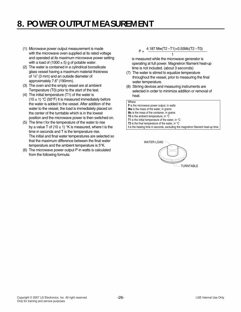
(6) The microwave power output P in watts is calculatedfrom the following formula:
4.187 Mw(T2 –T1)+0.55Mc(T2 –T0)t
is measured while the microwave generator isoperating at full power. Magnetron filament heat-uptime is not included. (about 3 seconds)
(7) The water is stirred to equalize temperaturethroughout the vessel, prior to measuring the finalwater temperature.
(8) Stirring devices and measuring instruments areselected in order to minimize addition or removal ofheat.
P =
WhereP is the microwave power output, in wattsMw is the mass of the water, in gramsMc is the mass of the container, in gramsT0 is the ambient temperature, in °CT1 is the initial temperature of the water, in °CT2 is the final temperature of the water, in °Ct is the heating time in seconds, excluding the magnetron filament heat-up time.
WATER LOAD
TURNTABLE
-27-
9. INTERLOCK SYSTEM 9-1. Interlock Mechanism
The door lock mechanism is a device which has been specially designed to eliminate completely microwave activitywhen the door is opened during cooking and thus to prevent the danger resulting from microwave leakage.
ADJUSTMENT PROCEDURESTo avoid possible exposure to microwave energy
leakage, adjust the door latches and interlockswitches, using the following procedure.
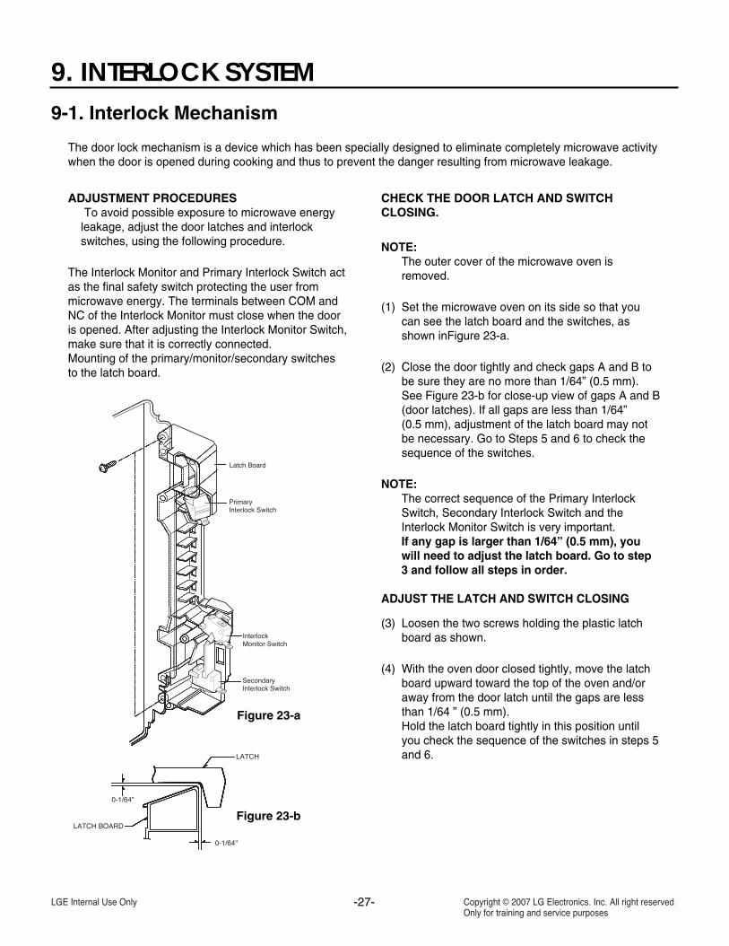
The Interlock Monitor and Primary Interlock Switch actas the final safety switch protecting the user frommicrowave energy. The terminals between COM andNC of the Interlock Monitor must close when the dooris opened. After adjusting the Interlock Monitor Switch,make sure that it is correctly connected.Mounting of the primary/monitor/secondary switchesto the latch board.
CHECK THE DOOR LATCH AND SWITCHCLOSING.
NOTE:The outer cover of the microwave oven isremoved.
(1) Set the microwave oven on its side so that youcan see the latch board and the switches, asshown inFigure 23-a.
(2) Close the door tightly and check gaps A and B tobe sure they are no more than 1/64” (0.5 mm).See Figure 23-b for close-up view of gaps A and B(door latches). If all gaps are less than 1/64”(0.5 mm), adjustment of the latch board may notbe necessary. Go to Steps 5 and 6 to check thesequence of the switches.
NOTE:The correct sequence of the Primary InterlockSwitch, Secondary Interlock Switch and theInterlock Monitor Switch is very important.If any gap is larger than 1/64” (0.5 mm), youwill need to adjust the latch board. Go to step3 and follow all steps in order.
ADJUST THE LATCH AND SWITCH CLOSING
(3) Loosen the two screws holding the plastic latchboard as shown.
(4) With the oven door closed tightly, move the latchboard upward toward the top of the oven and/oraway from the door latch until the gaps are lessthan 1/64 ” (0.5 mm).Hold the latch board tightly in this position untilyou check the sequence of the switches in steps 5and 6.
Figure 23-a
Figure 23-b
-28-
SPECIFICATIONS
TEST THE LATCH AND SWITCH SEQUENCE
(5) Open the oven door slowly. Watch the door latchand the Secondary Switch. Release the rod andlever on the switches to make sure they are zeroto the body of the switches in the followingsequence:
-Primary Interlock Switch-Secondary Interlock Switch-Interlock Monitor Switch
Adjust the latch board until the switches operate inthis sequence. See Steps 3 and 4.
(6) Close the oven door slowly and be sure it is tightlyclosed. Watch the three switches to make surethey are zero to the body of the switches in thefollowing sequence:
-Interlock Monitor Switch-Primary Interlock Switch-Secondary Interlock Switch
NOTE: The Interlock Monitor Switch is an addedsafety check on the Primary andSecondary Interlock Switches. If thePrimary and Secondary Interlock Switchesallow the oven to operate with the dooropen, the Monitor Switch will blow the
fuse.
(7) When you achieve the proper sequence ofswitches in Steps 5 and 6, tighten the latch boardscrews at that point.
TEST THE MICROWAVE ENERGY LEAKAGE
Make sure the microwave energy leakage is below thelimit of 1mW/cm2 (with a 275 ml water load) and5mW/cm2 (with a 275 ml water load without thecabinet) when measured with a survey meter.
-29-
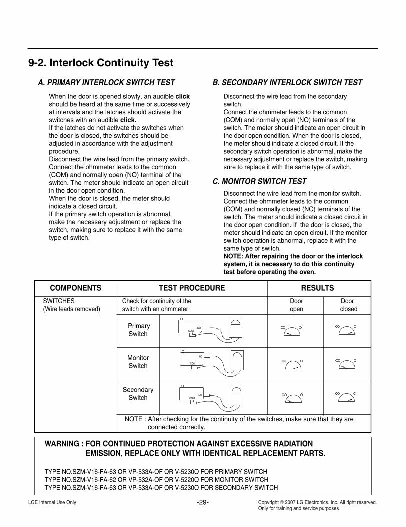
9-2. Interlock Continuity Test
A. PRIMARY INTERLOCK SWITCH TEST
When the door is opened slowly, an audible clickshould be heard at the same time or successivelyat intervals and the latches should activate theswitches with an audible click.If the latches do not activate the switches whenthe door is closed, the switches should beadjusted in accordance with the adjustmentprocedure.Disconnect the wire lead from the primary switch.Connect the ohmmeter leads to the common(COM) and normally open (NO) terminal of theswitch. The meter should indicate an open circuitin the door open condition.When the door is closed, the meter shouldindicate a closed circuit.If the primary switch operation is abnormal, make the necessary adjustment or replace theswitch, making sure to replace it with the sametype of switch.
B. SECONDARY INTERLOCK SWITCH TEST
Disconnect the wire lead from the secondaryswitch.Connect the ohmmeter leads to the common(COM) and normally open (NO) terminals of theswitch. The meter should indicate an open circuit inthe door open condition. When the door is closed,the meter should indicate a closed circuit. If thesecondary switch operation is abnormal, make thenecessary adjustment or replace the switch, makingsure to replace it with the same type of switch.
C. MONITOR SWITCH TESTDisconnect the wire lead from the monitor switch.Connect the ohmmeter leads to the common(COM) and normally closed (NC) terminals of theswitch. The meter should indicate a closed circuit inthe door open condition. If the door is closed, themeter should indicate an open circuit. If the monitorswitch operation is abnormal, replace it with thesame type of switch.NOTE: After repairing the door or the interlocksystem, it is necessary to do this continuitytest before operating the oven.
COMPONENTS TEST PROCEDURE RESULTS
SWITCHES Check for continuity of the Door Door(Wire leads removed) switch with an ohmmeter open closed
PrimarySwitch
MonitorSwitch
SecondarySwitch
NOTE : After checking for the continuity of the switches, make sure that they areconnected correctly.
WARNING : FOR CONTINUED PROTECTION AGAINST EXCESSIVE RADIATIONEMISSION, REPLACE ONLY WITH IDENTICAL REPLACEMENT PARTS.
TYPE NO.SZM-V16-FA-63 OR VP-533A-OF OR V-5230Q FOR PRIMARY SWITCHTYPE NO.SZM-V16-FA-62 OR VP-532A-OF OR V-5220Q FOR MONITOR SWITCHTYPE NO.SZM-V16-FA-63 OR VP-533A-OF OR V-5230Q FOR SECONDARY SWITCH
NOCOM
NC
COM
NOCOM
-30-
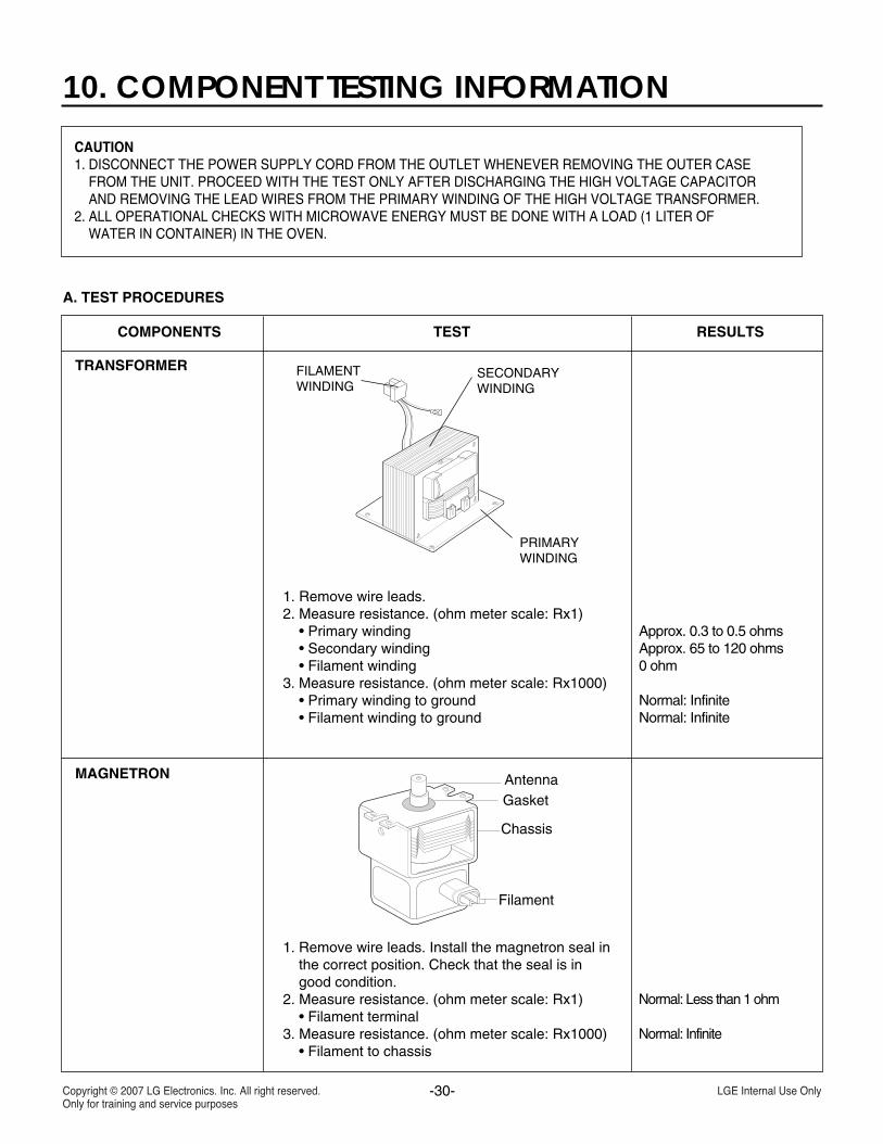
10. COMPONENT TESTING INFORMATION
CAUTION1. DISCONNECT THE POWER SUPPLY CORD FROM THE OUTLET WHENEVER REMOVING THE OUTER CASE
FROM THE UNIT. PROCEED WITH THE TEST ONLY AFTER DISCHARGING THE HIGH VOLTAGE CAPACITORAND REMOVING THE LEAD WIRES FROM THE PRIMARY WINDING OF THE HIGH VOLTAGE TRANSFORMER.
2. ALL OPERATIONAL CHECKS WITH MICROWAVE ENERGY MUST BE DONE WITH A LOAD (1 LITER OFWATER IN CONTAINER) IN THE OVEN.
A. TEST PROCEDURES
TRANSFORMER
MAGNETRON
1. Remove wire leads.2. Measure resistance. (ohm meter scale: Rx1)
• Primary winding • Secondary winding• Filament winding
3. Measure resistance. (ohm meter scale: Rx1000)• Primary winding to ground• Filament winding to ground
1. Remove wire leads. Install the magnetron seal inthe correct position. Check that the seal is ingood condition.
2. Measure resistance. (ohm meter scale: Rx1)• Filament terminal
3. Measure resistance. (ohm meter scale: Rx1000)• Filament to chassis
Normal: Less than 1 ohm
Normal: Infinite
COMPONENTS TEST RESULTS
SECONDARYWINDING
PRIMARYWINDING
FILAMENTWINDING
Approx. 0.3 to 0.5 ohms Approx. 65 to 120 ohms 0 ohm
Normal: Infinite Normal: Infinite
Filament
AntennaGasket
Chassis
-31-
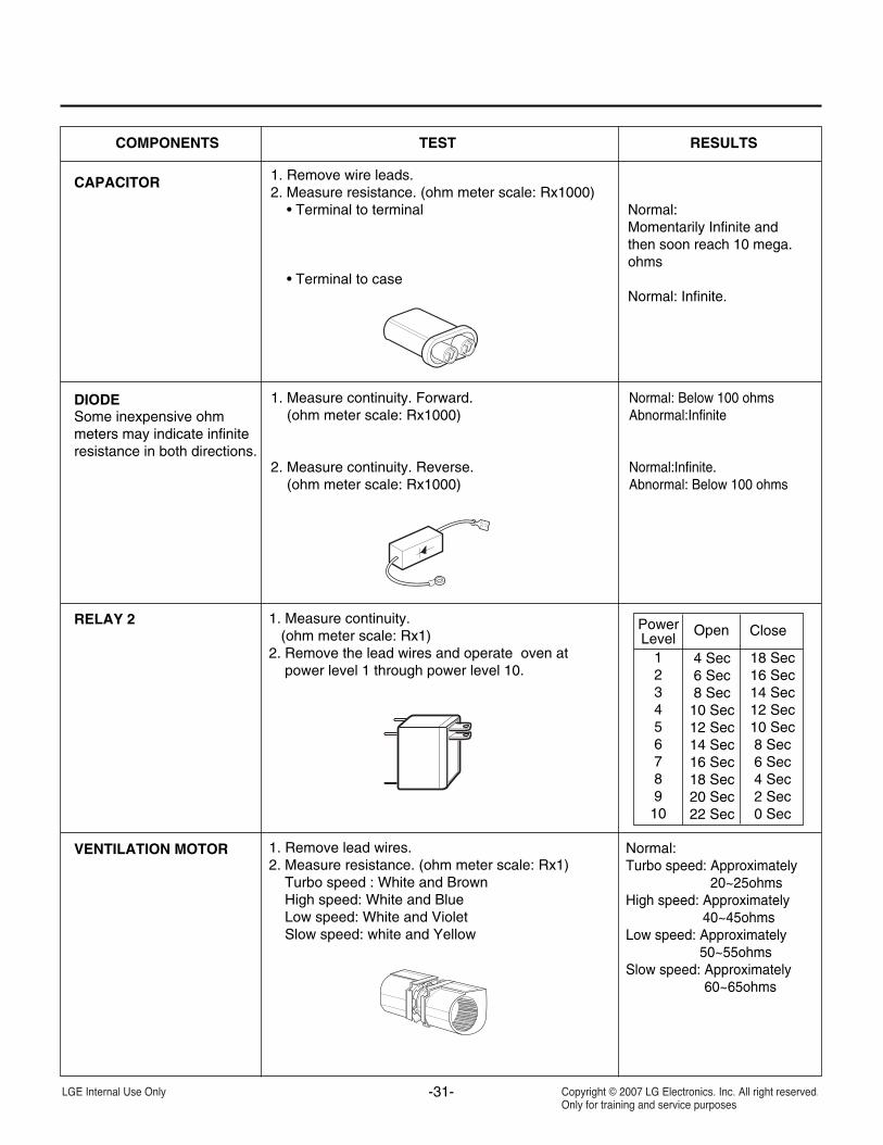
COMPONENTS TEST RESULTS
Normal:Momentarily Infinite andthen soon reach 10 mega.ohms
Normal: Infinite.
Normal: Below 100 ohmsAbnormal:Infinite
Normal:Infinite.Abnormal: Below 100 ohms
1. Remove wire leads.2. Measure resistance. (ohm meter scale: Rx1000)
• Terminal to terminal
• Terminal to case
1. Measure continuity. Forward.(ohm meter scale: Rx1000)
2. Measure continuity. Reverse.(ohm meter scale: Rx1000)
CAPACITOR
DIODESome inexpensive ohmmeters may indicate infiniteresistance in both directions.
1. Measure continuity.(ohm meter scale: Rx1)
2. Remove the lead wires and operate oven atpower level 1 through power level 10.
RELAY 2
1. Remove lead wires.2. Measure resistance. (ohm meter scale: Rx1)
Turbo speed : White and BrownHigh speed: White and BlueLow speed: White and VioletSlow speed: white and Yellow
Normal:Turbo speed: Approximately
20~25ohmsHigh speed: Approximately
40~45ohmsLow speed: Approximately
50~55ohmsSlow speed: Approximately
60~65ohms
VENTILATION MOTOR
PowerLevel
Open Close
12345678910
4 Sec6 Sec8 Sec10 Sec12 Sec14 Sec16 Sec18 Sec20 Sec22 Sec
18 Sec16 Sec14 Sec12 Sec10 Sec8 Sec6 Sec4 Sec2 Sec0 Sec
-32-
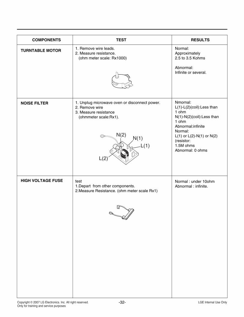
COMPONENTS TEST RESULTS
Normal: Approximately2.5 to 3.5 Kohms
Abnormal:Infinite or several.
Nmornal:L(1)-L(2)(coil):Less than1 ohmN(1)-N(2)(coil):Less than1 ohmAbnormal:infiniteNormal:L(1) or L(2)-N(1) or N(2)(resistor:1.5M ohmsAbnormal: 0 ohms
Normal : under 10ohmAbnormal : infinite.
1. Remove wire leads.2. Measure resistance.
(ohm meter scale: Rx1000)
1. Unplug microwave oven or disconnect power.2. Remove wire3. Measure resistance
(ohmmeter scale:Rx1).
test1.Depart from other components.2.Measure Resistance. (ohm meter scale Rx1)
TURNTABLE MOTOR
NOISE FILTER
HIGH VOLTAGE FUSE
L(1)
L(2)
N(2)N(1)
-33-
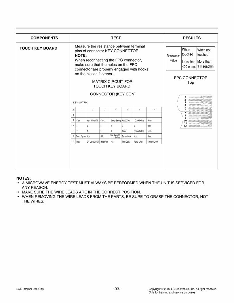
COMPONENTS TEST RESULTS
Measure the resistance between terminalpins of connector KEY CONNECTOR.NOTE:When reconnecting the FPC connector,make sure that the holes on the FPCconnector are properly engaged with hookson the plastic fastener.
MATRIX CIRCUIT FORTOUCH KEY BOARD
CONNECTOR (KEY CON)
TOUCH KEY BOARD
Resistancevalue
Whentouched
Less than400 ohms
When nottouched
More than1 megaohm
FPC CONNECTORTop
NOTES:• A MICROWAVE ENERGY TEST MUST ALWAYS BE PERFORMED WHEN THE UNIT IS SERVICED FOR
ANY REASON.• MAKE SURE THE WIRE LEADS ARE IN THE CORRECT POSITION.• WHEN REMOVING THE WIRE LEADS FROM THE PARTS, BE SURE TO GRASP THE CONNECTOR, NOT
THE WIRES.
KEY MATRIX
Turntable On/OffPower LevelTime CookHold WarmC/T Lamp On/OffStart13
MoreSensor Cooktime & weightDefrostN.A N.A
N.A
N.ASensor Popcorn12
LessSensor ReheatTimer098711
Melt65432110
SoftenQuick DefrostAdd 30 Sec.Energy SavingClockVent Hi/Low/OffClear9
8
76543212st
11. DISASSEMBLY INSTRUCTIONS
-34-
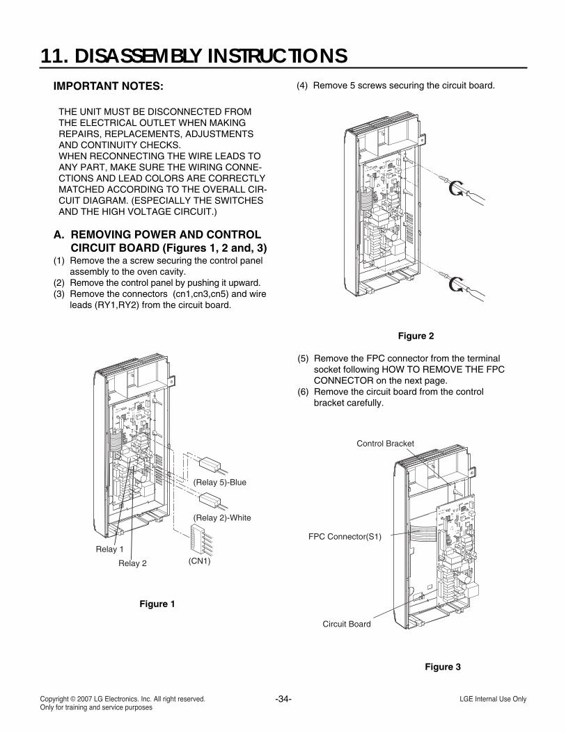
IMPORTANT NOTES:
THE UNIT MUST BE DISCONNECTED FROMTHE ELECTRICAL OUTLET WHEN MAKINGREPAIRS, REPLACEMENTS, ADJUSTMENTSAND CONTINUITY CHECKS.WHEN RECONNECTING THE WIRE LEADS TOANY PART, MAKE SURE THE WIRING CONNE-CTIONS AND LEAD COLORS ARE CORRECTLYMATCHED ACCORDING TO THE OVERALL CIR-CUIT DIAGRAM. (ESPECIALLY THE SWITCHESAND THE HIGH VOLTAGE CIRCUIT.)
A. REMOVING POWER AND CONTROLCIRCUIT BOARD (Figures 1, 2 and, 3)
(1) Remove the a screw securing the control panelassembly to the oven cavity.
(2) Remove the control panel by pushing it upward. (3) Remove the connectors (cn1,cn3,cn5) and wire
leads (RY1,RY2) from the circuit board.
(4) Remove 5 screws securing the circuit board.
(CN1)
(Relay 2)-White
(Relay 5)-Blue
Relay 2
Relay 1
Circuit Board
FPC Connector(S1)
Control Bracket
(5) Remove the FPC connector from the terminalsocket following HOW TO REMOVE THE FPCCONNECTOR on the next page.
(6) Remove the circuit board from the controlbracket carefully.
Figure 1
Figure 2
Figure 3
-35-
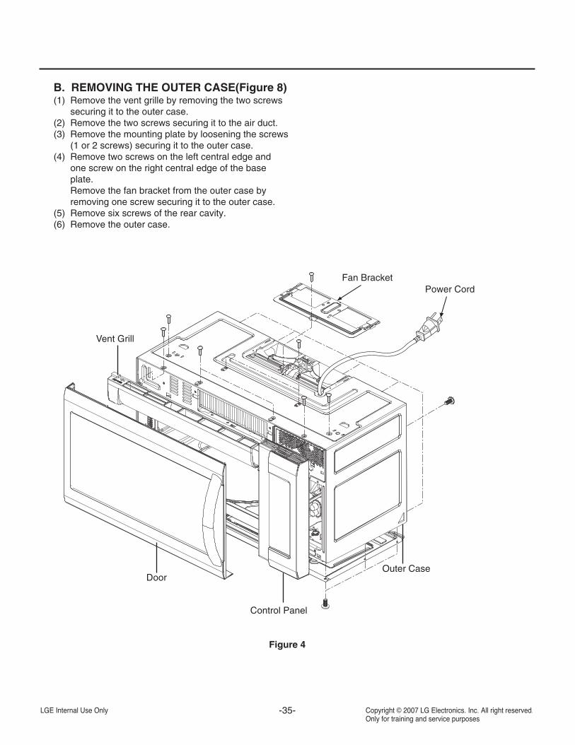
B. REMOVING THE OUTER CASE(Figure 8)(1) Remove the vent grille by removing the two screws
securing it to the outer case.(2) Remove the two screws securing it to the air duct.(3) Remove the mounting plate by loosening the screws
(1 or 2 screws) securing it to the outer case.(4) Remove two screws on the left central edge and
one screw on the right central edge of the baseplate.Remove the fan bracket from the outer case byremoving one screw securing it to the outer case.
(5) Remove six screws of the rear cavity.(6) Remove the outer case.
Fan Bracket
DoorOuter Case
Vent Grill
Control Panel
Power Cord
Figure 4
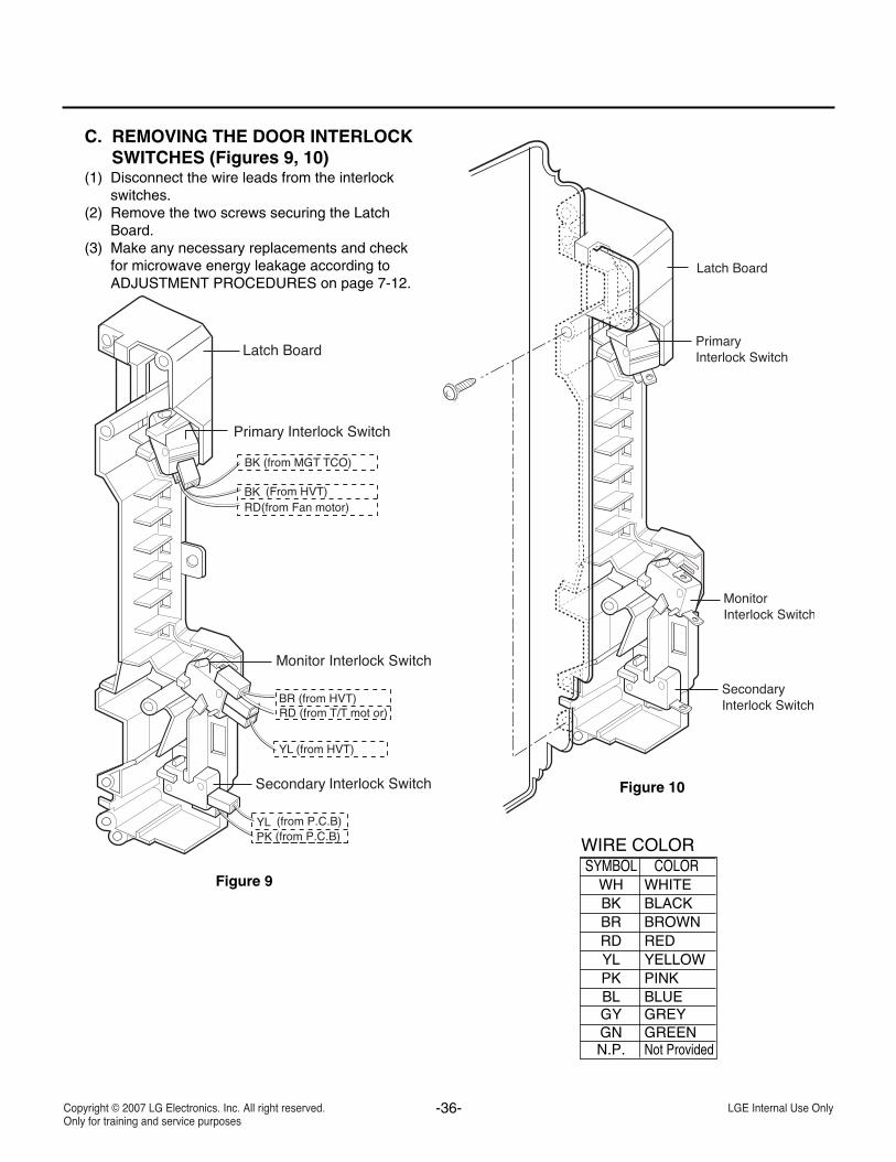
C. REMOVING THE DOOR INTERLOCKSWITCHES (Figures 9, 10)
(1) Disconnect the wire leads from the interlockswitches.
(2) Remove the two screws securing the LatchBoard.
(3) Make any necessary replacements and checkfor microwave energy leakage according toADJUSTMENT PROCEDURES on page 7-12.
YL
YL (from HVT)
BR (from HVT)
PK
RD (from T/T mot or)
Figure 9
Figure 10
WIRE COLORSYMBOL COLOR
WH WHITEBK BLACKBR BROWNRD REDYL YELLOWPK PINKBL BLUEGY GREYGN GREENN.P. Not Provided
-36-

-37-
D. REMOVING MAGNETRON(Figures 11 Through 12)
(1) Remove the vent grill by loosening the onescrews.(Figure 11)
(2) Remove fan bracket and outer case. See page7-6.
(3) Remove the four tap tite screws securing themagnetron to the wave guide.
(4) Disconnect the lead wire.(5) Remove the magnetron VERY CAREFULLY.
NOTES:• When removing the magnetron, make sure that its
dome does not hit any adjacent parts, or it may bedamaged.
• When replacing the magnetron, be sure to installthe magnetron gasket in the correct position andbe sure that the gasket is in good condition.
• After replacing the magnetron, check formicrowave energy leakage with a survey meter.Checked microwave energy leakage must bebelow the limit of 5 mW/cm2. (All serviceadjustments should be made for minimummicrowave energy leakage readings.)
E. REMOVING STIRRER FAN(Figures 13 and 14)
(1) Remove one rivet assembly securing it to theoven upper plate by using a knife blade.
(2) Remove the stirrer fan cover.(3) Remove the stirrer fan.
Fan Bracket
vent grill
Magnetron
Figure 12
Figure 11
Figure 13
Figure 14
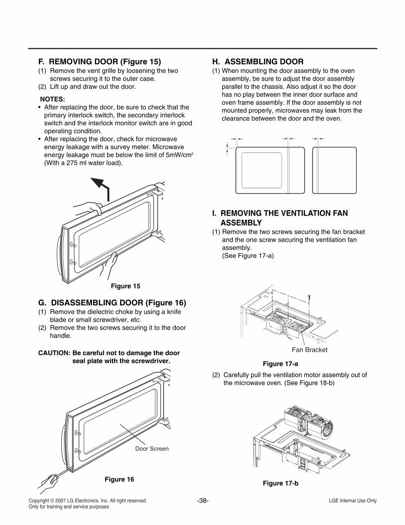
F. REMOVING DOOR (Figure 15)(1) Remove the vent grille by loosening the two
screws securing it to the outer case.(2) Lift up and draw out the door.
NOTES:• After replacing the door, be sure to check that the
primary interlock switch, the secondary interlockswitch and the interlock monitor switch are in goodoperating condition.
• After replacing the door, check for microwaveenergy leakage with a survey meter. Microwaveenergy leakage must be below the limit of 5mW/cm2
(With a 275 ml water load).
G. DISASSEMBLING DOOR (Figure 16)(1) Remove the dielectric choke by using a knife
blade or small screwdriver, etc.(2) Remove the two screws securing it to the door
handle.
CAUTION: Be careful not to damage the doorseal plate with the screwdriver.
H. ASSEMBLING DOOR(1) When mounting the door assembly to the oven
assembly, be sure to adjust the door assemblyparallel to the chassis. Also adjust it so the doorhas no play between the inner door surface andoven frame assembly. If the door assembly is notmounted properly, microwaves may leak from theclearance between the door and the oven.
I. REMOVING THE VENTILATION FANASSEMBLY
(1) Remove the two screws securing the fan bracketand the one screw securing the ventilation fanassembly.(See Figure 17-a)
(2) Carefully pull the ventilation motor assembly out ofthe microwave oven. (See Figure 18-b)
Figure 16
Fan Bracket
Figure 15
Figure 17-a
Figure 17-b
-38-
-39-
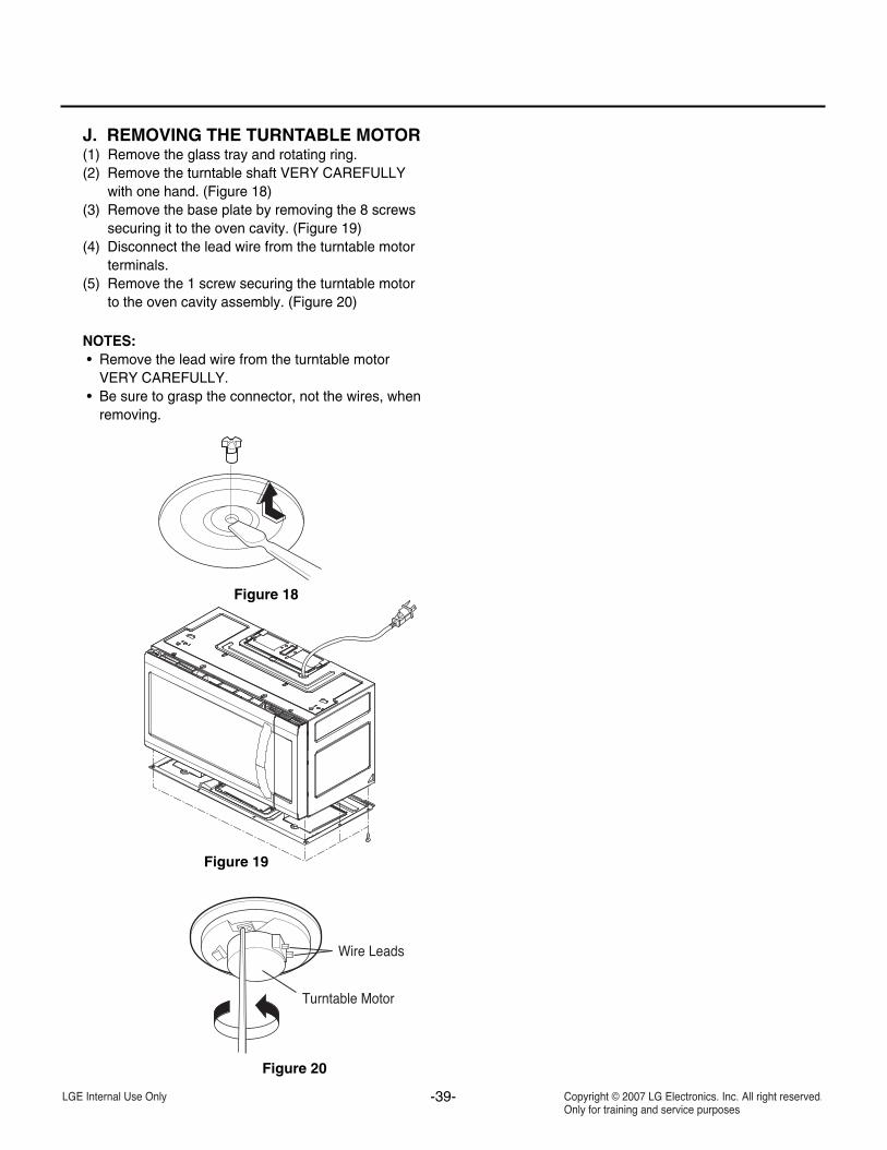
J. REMOVING THE TURNTABLE MOTOR(1) Remove the glass tray and rotating ring.(2) Remove the turntable shaft VERY CAREFULLY
with one hand. (Figure 18)(3) Remove the base plate by removing the 8 screws
securing it to the oven cavity. (Figure 19)(4) Disconnect the lead wire from the turntable motor
terminals.(5) Remove the 1 screw securing the turntable motor
to the oven cavity assembly. (Figure 20)
NOTES:• Remove the lead wire from the turntable motor
VERY CAREFULLY.• Be sure to grasp the connector, not the wires, when
removing.
Figure 18
Figure 19
Figure 20
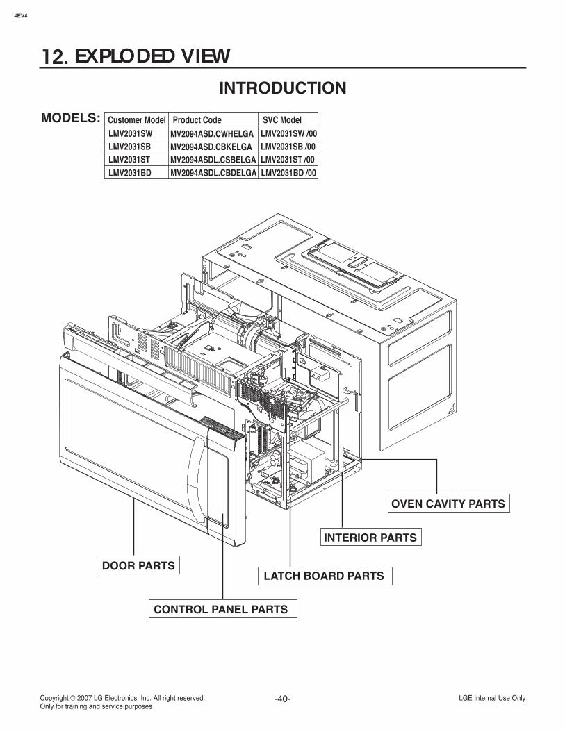
EXPLODED VIEWINTRODUCTION
OVEN CAVITY PARTS
INTERIOR PARTS
LATCH BOARD PARTS
CONTROL PANEL PARTS
DOOR PARTS
#EV#
Customer Model Product Code SVC Model
Customer Model Product Code SVC Model
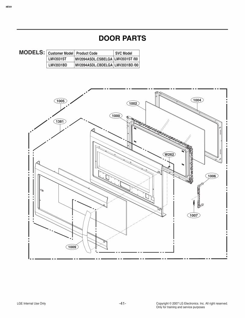
DOOR PARTS
1004
1000
10021005
1381
1009
1007
1006
W262
#EV#
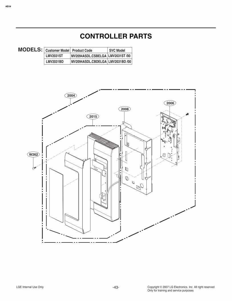
2004
2015
2008
2006
W262
#EV#
CONTROLLER PARTS
Customer Model Product Code SVC Model
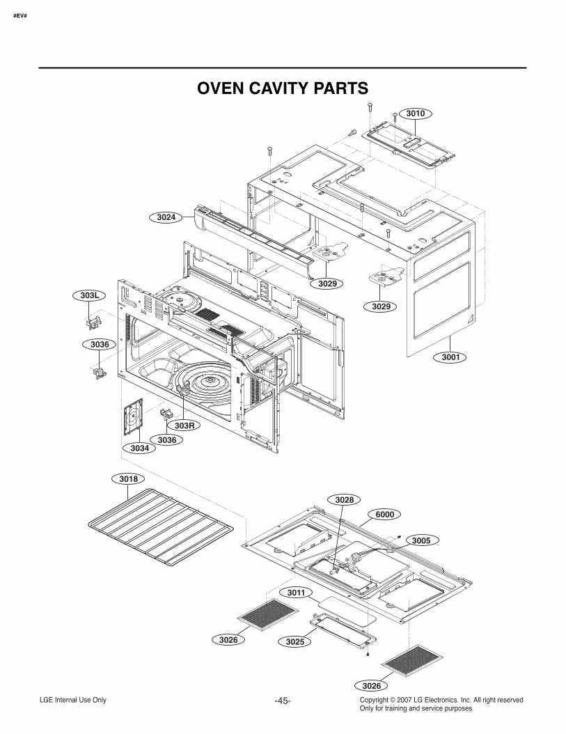
OVEN CAVITY PARTS
6000
3005
3025
3026
3026
3011
3028
3010
3001
30343036
303R
3018
3036
303L
3024
3029
3029
#EV#
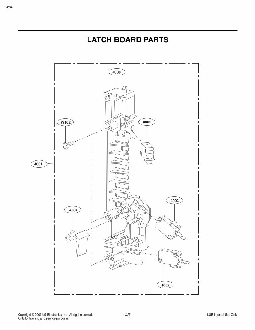
W102
4000
4001
4004
4002
4003
4002
LATCH BOARD PARTS
#EV#
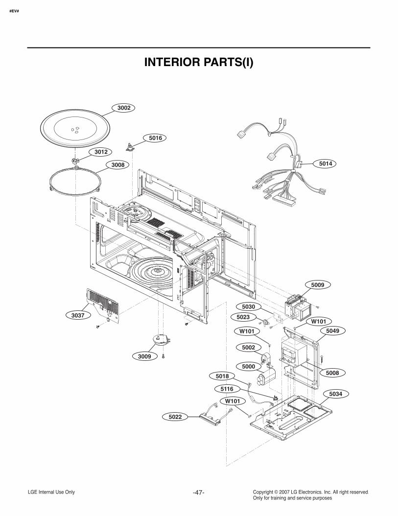
INTERIOR PARTS(I)
#EV#
3037
3009
5014
3002
3012
5016
5030
5002
5000
5116
5023
5009
5049
W101
W101
W101
5008
5034
5022
5018
3008
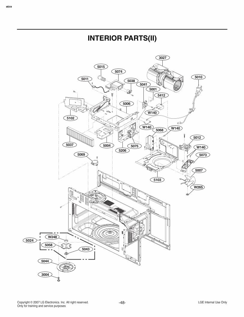
INTERIOR PARTS(II)
#EV#
5010
5012
5073
5007
W265
5412
5103
50045037
5102
5068 W140
W140
W140
5001
5006
5069
5041
3027
5206
5038
50745015
5011
5058
W248
5044
5043
3004
5024
5075
W140
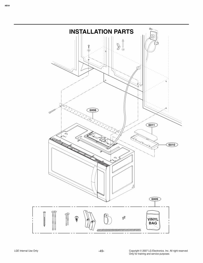
6011
6010
6009
6008
VINYLBAG
INSTALLATION PARTS
#EV#

Recommended