1
2006 Perimeter Rd. Greenville, SC 29605 Toll Free: 800-435-9340 - Phone: 864-277-5870 Fax: 864-235-9661 - www.mclaughlinunderground.com Email: [email protected]
Safety and Operation Manual VX200 Vacuum System Table of Contents
Section
Forward �������������������������� 2 Hazard Alert Decal ���������������������. 3 Hazard Alert Decal Placement ����������������. 9 Operation Controls and Placement ��������������. 14 Specifications and Maintenance ���������������.. 20 LCD Display ������������������������. 23 Operation of Machine ��������������������. 30 Warranty and Return Policy �����������������.. 39
Manual Part No. E850008 © 2016 by McLaughlin Group, Inc. Revised 10.04.2016
All rights reserved. No part of this manual may be reproduced in any form, or by any means without prior written permission of McLaughlin Group, Inc.
2
FORWARD This manual contains important safety information and operational instructions for your Vermeer/McLaughlin system. Read and understand this manual before operating this equipment. Failure to do so may result in serious personal injury or equipment damage. Keep this manual with the equipment at all times for future reference. If you sell this equipment, be sure to give this manual to the new owner. A replacement copy of this manual is available through your local Vermeer dealer or by contacting McLaughlin Group, Inc. directly at:
McLaughlin Group, Inc. 2006 Perimeter Road Greenville, SC 29605 Toll free: 800-435-9340 Worldwide: 864-277-5870 Fax: 864-235-9661 Email: [email protected] www.mclaughlinunderground.com
The illustrations, instructions and specifications in this manual are subject to change. McLaughlin Group, Inc. reserves the right to make product changes at any time. Contact your Vermeer dealer for the latest information on McLaughlin vacuums, piercing tools and G3 locators.
3
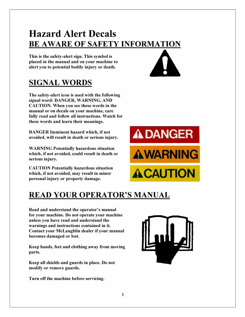
Hazard Alert Decals
BE AWARE OF SAFETY INFORMATION
This is the safety-alert sign. This symbol is
placed in the manual and on your machine to
alert you to potential bodily injury or death.
SIGNAL WORDS
The safety-alert icon is used with the following
signal word: DANGER, WARNING, AND
CAUTION. When you see these words in the
manual or on decals on your machine, care
fully read and follow all instructions. Watch for
these words and learn their meanings.
DANGER Imminent hazard which, if not
avoided, will result in death or serious injury.
WARNING Potentially hazardous situation
which, if not avoided, could result in death or
serious injury. CAUTION Potentially hazardous situation
which, if not avoided, may result in minor
personal injury or property damage.
READ YOUR OPERATOR’S MANUAL
Read and understand the operator’s manual
for your machine. Do not operate your machine
unless you have read and understand the
warnings and instructions contained in it.
Contact your McLaughlin dealer if your manual
becomes damaged or lost.
Keep hands, feet and clothing away from moving
parts.
Keep all shields and guards in place. Do not
modify or remove guards.
Turn off the machine before servicing.
4
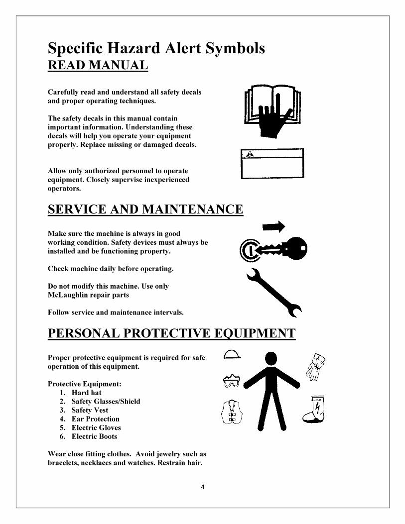
Specific Hazard Alert Symbols
READ MANUAL
Carefully read and understand all safety decals
and proper operating techniques.
The safety decals in this manual contain
important information. Understanding these
decals will help you operate your equipment
properly. Replace missing or damaged decals.
Allow only authorized personnel to operate
equipment. Closely supervise inexperienced
operators.
SERVICE AND MAINTENANCE
Make sure the machine is always in good
working condition. Safety devices must always be
installed and be functioning property.
Check machine daily before operating.
Do not modify this machine. Use only
McLaughlin repair parts
Follow service and maintenance intervals.
PERSONAL PROTECTIVE EQUIPMENT
Proper protective equipment is required for safe
operation of this equipment.
Protective Equipment:
1. Hard hat
2. Safety Glasses/Shield
3. Safety Vest
4. Ear Protection
5. Electric Gloves
6. Electric Boots
Wear close fitting clothes. Avoid jewelry such as
bracelets, necklaces and watches. Restrain hair.
5
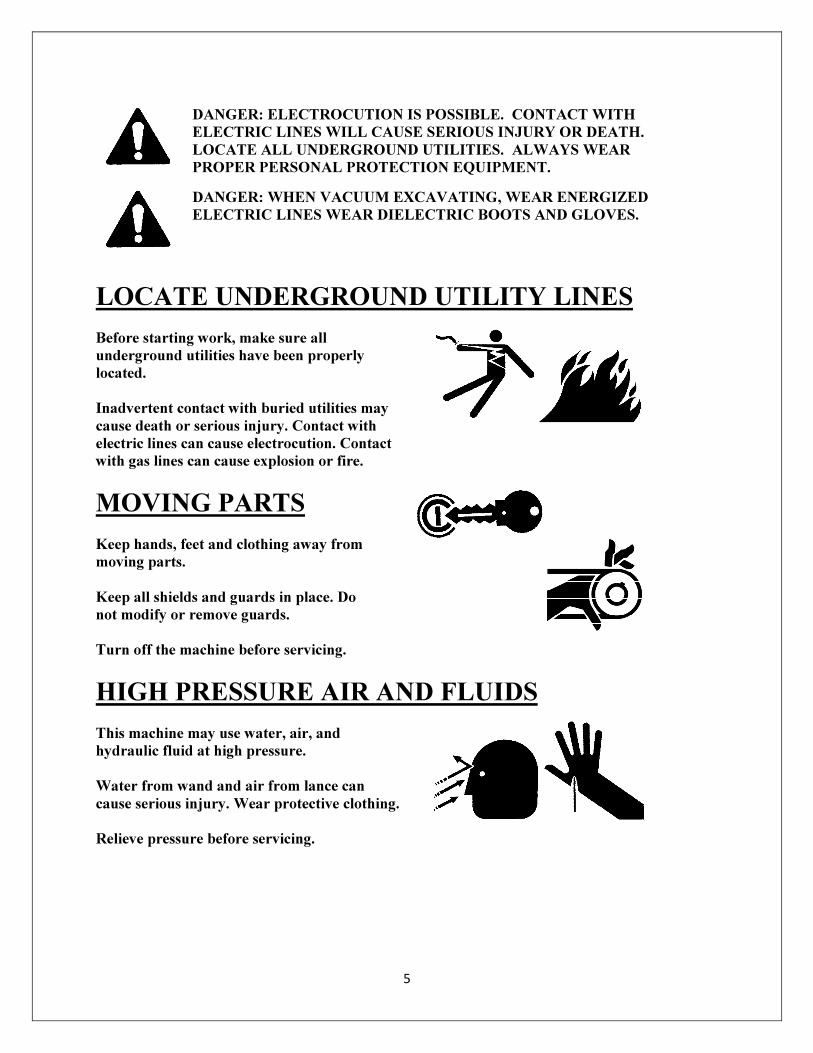
DANGER: ELECTROCUTION IS POSSIBLE. CONTACT WITH
ELECTRIC LINES WILL CAUSE SERIOUS INJURY OR DEATH.
LOCATE ALL UNDERGROUND UTILITIES. ALWAYS WEAR
PROPER PERSONAL PROTECTION EQUIPMENT.
DANGER: WHEN VACUUM EXCAVATING, WEAR ENERGIZED
ELECTRIC LINES WEAR DIELECTRIC BOOTS AND GLOVES.
LOCATE UNDERGROUND UTILITY LINES
Before starting work, make sure all
underground utilities have been properly
located.
Inadvertent contact with buried utilities may
cause death or serious injury. Contact with
electric lines can cause electrocution. Contact
with gas lines can cause explosion or fire.
MOVING PARTS
Keep hands, feet and clothing away from
moving parts.
Keep all shields and guards in place. Do
not modify or remove guards.
Turn off the machine before servicing.
HIGH PRESSURE AIR AND FLUIDS
This machine may use water, air, and
hydraulic fluid at high pressure.
Water from wand and air from lance can
cause serious injury. Wear protective clothing.
Relieve pressure before servicing.
6
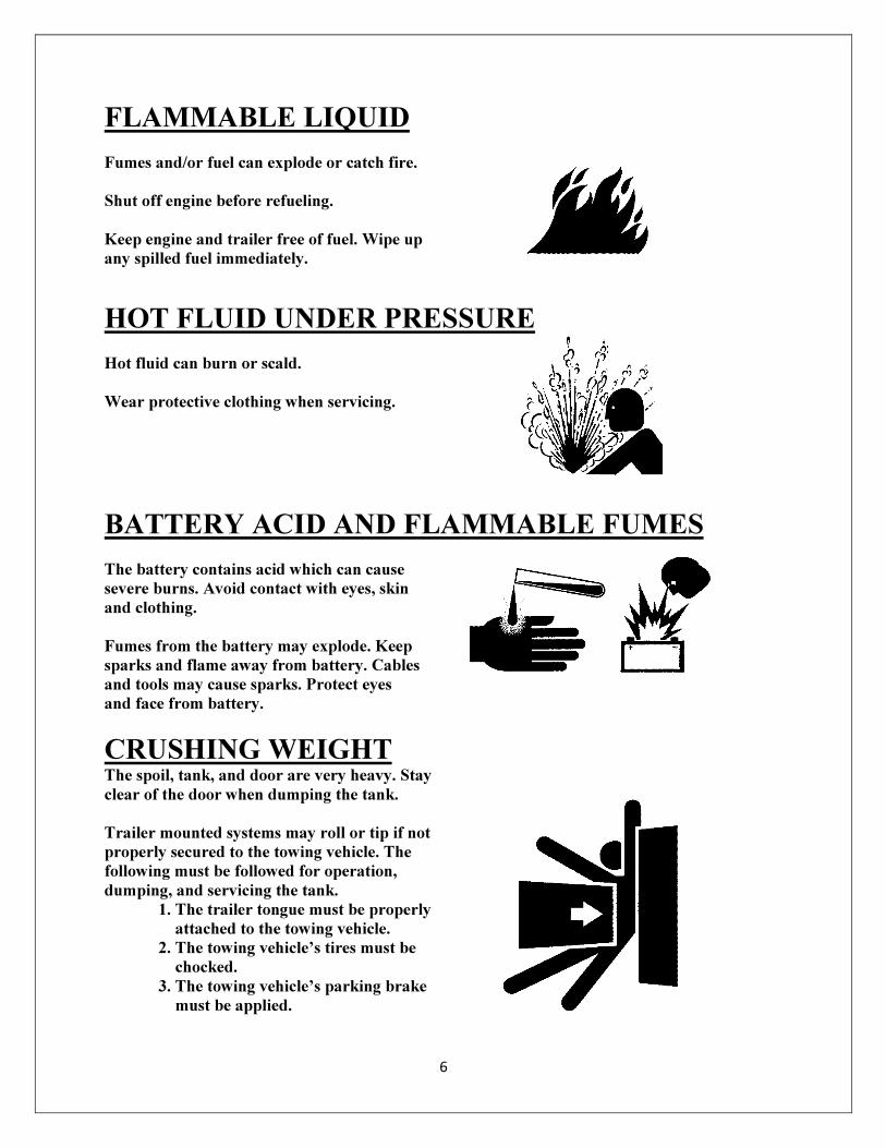
FLAMMABLE LIQUID
Fumes and/or fuel can explode or catch fire.
Shut off engine before refueling.
Keep engine and trailer free of fuel. Wipe up
any spilled fuel immediately.
HOT FLUID UNDER PRESSURE
Hot fluid can burn or scald.
Wear protective clothing when servicing.
BATTERY ACID AND FLAMMABLE FUMES
The battery contains acid which can cause
severe burns. Avoid contact with eyes, skin
and clothing.
Fumes from the battery may explode. Keep
sparks and flame away from battery. Cables
and tools may cause sparks. Protect eyes
and face from battery.
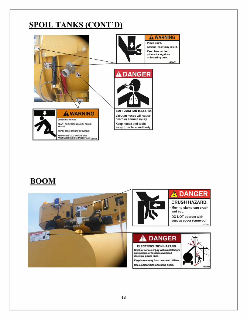
CRUSHING WEIGHT The spoil, tank, and door are very heavy. Stay
clear of the door when dumping the tank.
Trailer mounted systems may roll or tip if not
properly secured to the towing vehicle. The
following must be followed for operation,
dumping, and servicing the tank.
1. The trailer tongue must be properly
attached to the towing vehicle.
2. The towing vehicle’s tires must be
chocked.
3. The towing vehicle’s parking brake
must be applied.
7
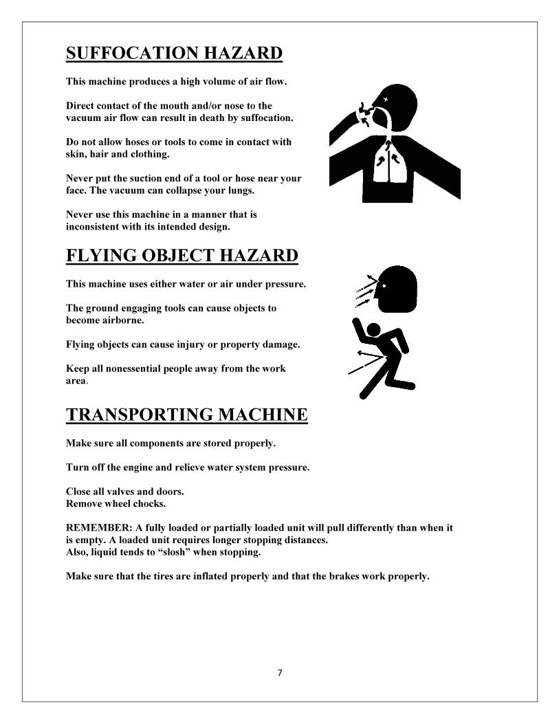
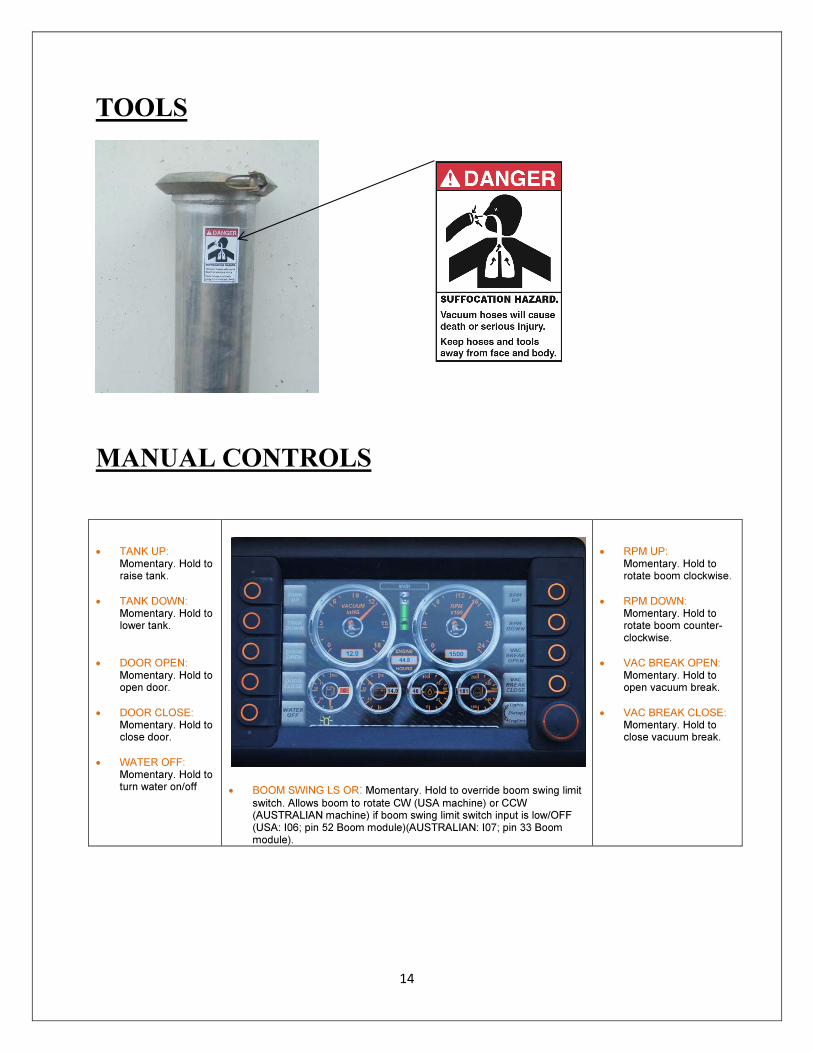
SUFFOCATION HAZARD
This machine produces a high volume of air flow.
Direct contact of the mouth and/or nose to the
vacuum air flow can result in death by suffocation.
Do not allow hoses or tools to come in contact with
skin, hair and clothing.
Never put the suction end of a tool or hose near your
face. The vacuum can collapse your lungs.
Never use this machine in a manner that is
inconsistent with its intended design.
FLYING OBJECT HAZARD
This machine uses either water or air under pressure.
The ground engaging tools can cause objects to
become airborne.
Flying objects can cause injury or property damage.
Keep all nonessential people away from the work
area.
TRANSPORTING MACHINE
Make sure all components are stored properly.
Turn off the engine and relieve water system pressure.
Close all valves and doors.
Remove wheel chocks.
REMEMBER: A fully loaded or partially loaded unit will pull differently than when it
is empty. A loaded unit requires longer stopping distances.
Also, liquid tends to “slosh” when stopping.
Make sure that the tires are inflated properly and that the brakes work properly.
8
WARNING: FAILURE TO FOLLOW ANY OR ALL OF THE SAFETY
INSTRUCTIONS IN THIS MANUAL, COULD RESULT IN DEATH OR
SERIOUS INJURY. DO NOT USE THIS MACHINE IN A MANNER
THAT IS INCONSISTENT WITH ITS INTENDED DESIGN.
9
Hazard Alert Decal Placement HAZARD ALERT DECAL MAINTENANCE
Hazard alert decals on your machine contain important information that will help
you operate the equipment safely.
Decals maintenance:
1. Keep decals clean. Clean with soap and water. Do not use harsh chemicals, or
spray decals directly with a high pressure washer.
2. Replace decals when they become damaged or hard to read. Clean the surface
of dirt, grease and oil before applying.
3. When replacing a machine component with a decal on it, replace the decal also.
4. See your local dealer or contact McLaughlin for replacement decals.
5. Replacement part number appears on each decal, as well as in this manual.
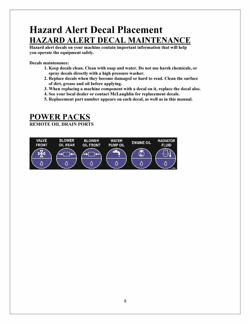
POWER PACKS REMOTE OIL DRAIN PORTS
10
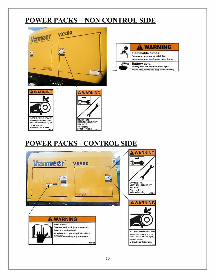
POWER PACKS – NON CONTROL SIDE
POWER PACKS - CONTROL SIDE
11
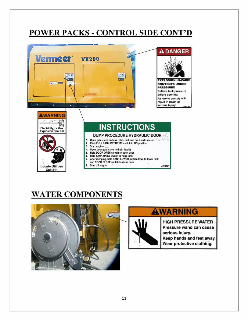
POWER PACKS - CONTROL SIDE CONT’D
WATER COMPONENTS
12
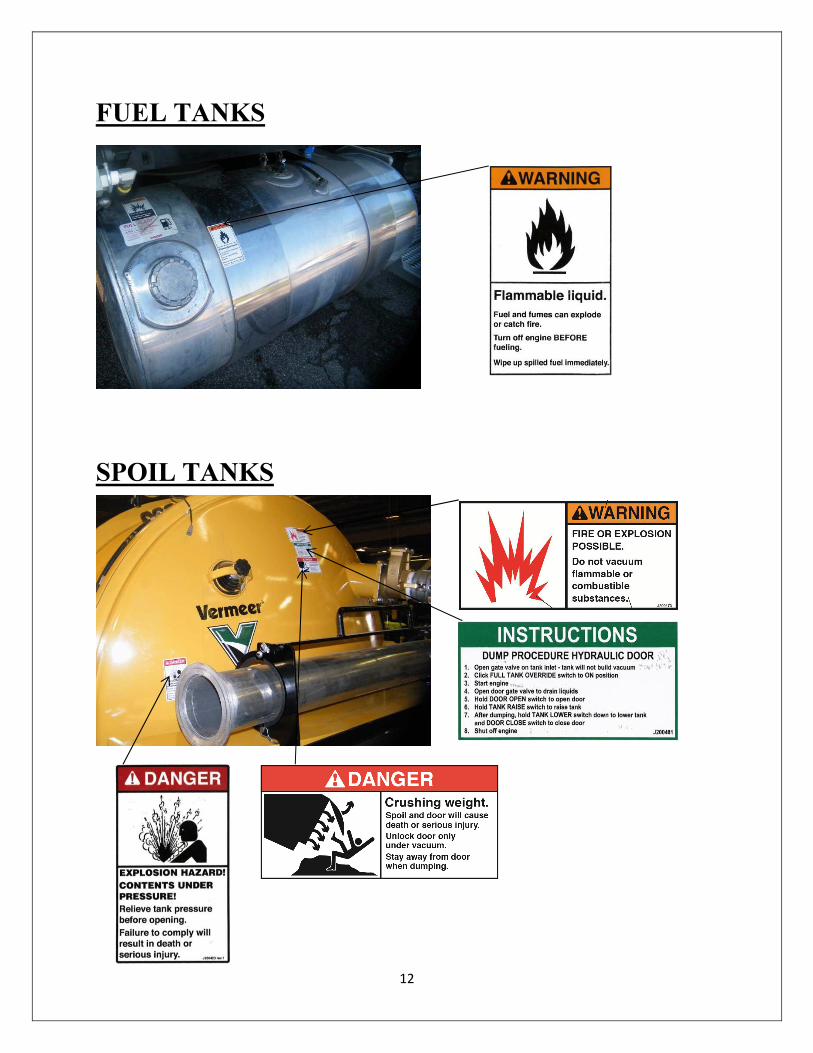
FUEL TANKS
SPOIL TANKS
13
SPOIL TANKS (CONT’D)
BOOM
14
MANUAL CONTROLS
• TANK UP: Momentary. Hold to raise tank.
• TANK DOWN: Momentary. Hold to lower tank.
• DOOR OPEN: Momentary. Hold to open door.
• DOOR CLOSE: Momentary. Hold to close door.
• WATER OFF: Momentary. Hold to turn water on/off
• BOOM SWING LS OR: Momentary. Hold to override boom swing limit switch. Allows boom to rotate CW (USA machine) or CCW (AUSTRALIAN machine) if boom swing limit switch input is low/OFF (USA: I06; pin 52 Boom module)(AUSTRALIAN: I07; pin 33 Boom module).
• RPM UP: Momentary. Hold to rotate boom clockwise.
• RPM DOWN: Momentary. Hold to rotate boom counter-clockwise.
• VAC BREAK OPEN: Momentary. Hold to open vacuum break.
• VAC BREAK CLOSE: Momentary. Hold to close vacuum break.
TOOLS
15
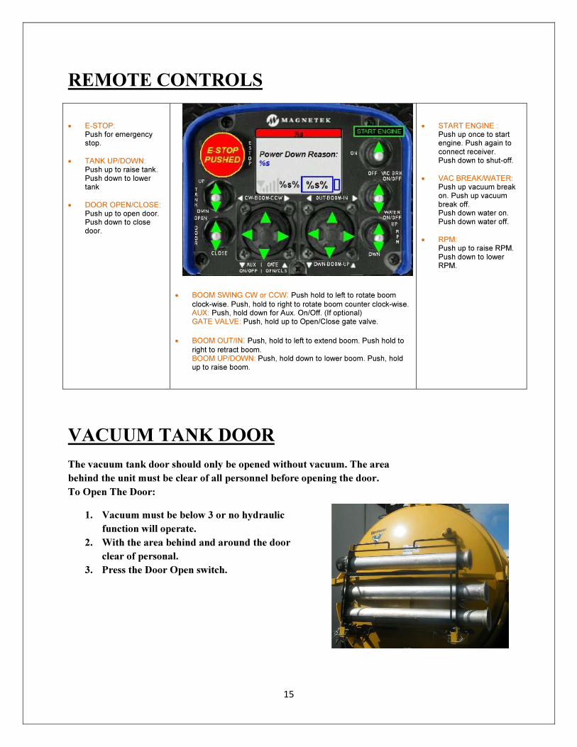
REMOTE CONTROLS
• E-STOP: Push for emergency stop.
• TANK UP/DOWN: Push up to raise tank. Push down to lower tank
• DOOR OPEN/CLOSE: Push up to open door. Push down to close door.
• BOOM SWING CW or CCW: Push hold to left to rotate boom clock-wise. Push, hold to right to rotate boom counter clock-wise. AUX: Push, hold down for Aux. On/Off. (If optional) GATE VALVE: Push, hold up to Open/Close gate valve.
• BOOM OUT/IN: Push, hold to left to extend boom. Push hold to right to retract boom. BOOM UP/DOWN: Push, hold down to lower boom. Push, hold up to raise boom.
• START ENGINE : Push up once to start engine. Push again to connect receiver. Push down to shut-off.
• VAC BREAK/WATER: Push up vacuum break on. Push up vacuum break off. Push down water on. Push down water off.
• RPM: Push up to raise RPM. Push down to lower RPM.
VACUUM TANK DOOR
The vacuum tank door should only be opened without vacuum. The area
behind the unit must be clear of all personnel before opening the door.
To Open The Door:
1. Vacuum must be below 3 or no hydraulic
function will operate.
2. With the area behind and around the door
clear of personal.
3. Press the Door Open switch.
16
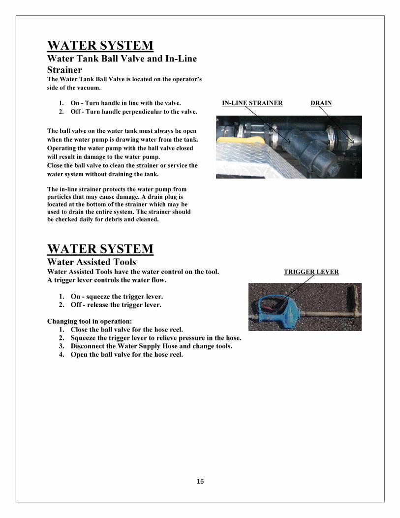
WATER SYSTEM Water Tank Ball Valve and In-Line
Strainer The Water Tank Ball Valve is located on the operator’s
side of the vacuum.
1. On - Turn handle in line with the valve. IN-LINE STRAINER DRAIN
2. Off - Turn handle perpendicular to the valve.
The ball valve on the water tank must always be open
when the water pump is drawing water from the tank.
Operating the water pump with the ball valve closed
will result in damage to the water pump.
Close the ball valve to clean the strainer or service the
water system without draining the tank.
The in-line strainer protects the water pump from
particles that may cause damage. A drain plug is
located at the bottom of the strainer which may be
used to drain the entire system. The strainer should
be checked daily for debris and cleaned.
WATER SYSTEM Water Assisted Tools
Water Assisted Tools have the water control on the tool. TRIGGER LEVER
A trigger lever controls the water flow.
1. On - squeeze the trigger lever. 2. Off - release the trigger lever.
Changing tool in operation:
1. Close the ball valve for the hose reel. 2. Squeeze the trigger lever to relieve pressure in the hose. 3. Disconnect the Water Supply Hose and change tools. 4. Open the ball valve for the hose reel.
17
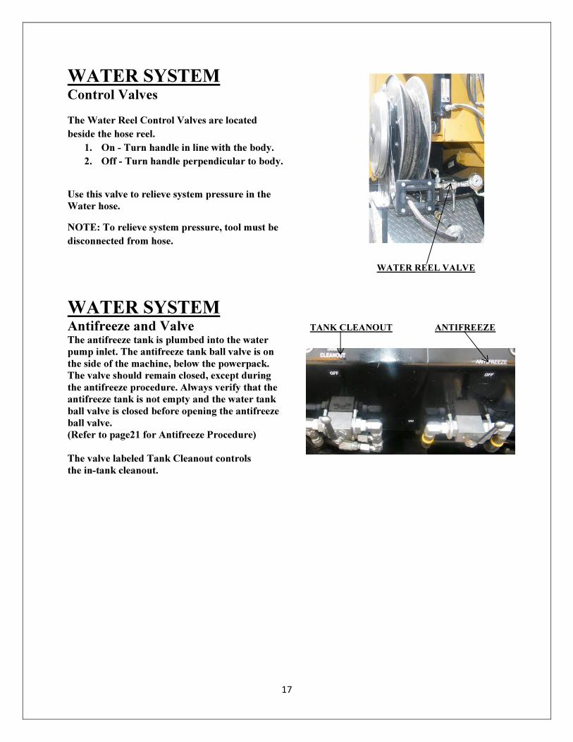
WATER SYSTEM Control Valves
The Water Reel Control Valves are located
beside the hose reel.
1. On - Turn handle in line with the body.
2. Off - Turn handle perpendicular to body.
Use this valve to relieve system pressure in the
Water hose.
NOTE: To relieve system pressure, tool must be
disconnected from hose.
WATER REEL VALVE
WATER SYSTEM Antifreeze and Valve TANK CLEANOUT ANTIFREEZE
The antifreeze tank is plumbed into the water
pump inlet. The antifreeze tank ball valve is on
the side of the machine, below the powerpack.
The valve should remain closed, except during
the antifreeze procedure. Always verify that the
antifreeze tank is not empty and the water tank
ball valve is closed before opening the antifreeze
ball valve.
(Refer to page21 for Antifreeze Procedure)
The valve labeled Tank Cleanout controls
the in-tank cleanout.

18
BOOM Manual Controls
• BOOM UP: Momentary. Hold to raise boom.
• BOOM DOWN: Momentary. Hold to lower boom.
• BOOM EXTEND: Momentary. Hold to extend boom.
• BOOM RETRACT: Momentary. Hold to retract boom.
• BOOM SWING LS OR: Momentary. Hold to override boom swing limit switch. Allows boom to rotate CW (USA machine) or CCW (AUSTRALIAN machine) if boom swing limit switch input is low/OFF (USA: I06; pin 52 Boom module)(AUSTRALIAN: I07; pin 33 Boom module).
• BOOM SWING CW: Momentary. Hold to rotate boom clockwise.
• BOOM SWING CCW: Momentary. Hold to rotate boom counter-clockwise.
• BOOM GATE OPEN: Momentary. Hold to open boom gate valve.
• BOOM GATE CLOSE: Momentary. Hold to close boom gate valve.
Remote Controls
19
Options
Arrow Board
The Arrow Board is located at the back, on the top
of the Spoil Tank. It signals directions to on coming
traffic to go around machine while working.
(For Functions see page.29)
Hot Box
The Hot Box is located on side of the truck.
The Hot Box is used to heat the water used by
the machine.
The Hot Box cannot be operated while
in transport. If operated during transport
the flame can be blown out and will cause
the unit to fill with fuel. If it ignites,
damage to the hot box or machine and
bodily injury is possible.
20
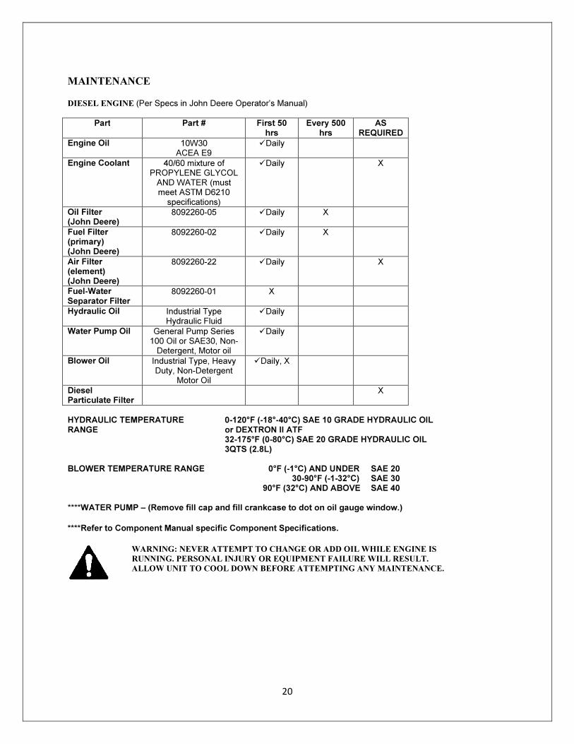
MAINTENANCE
DIESEL ENGINE (Per Specs in John Deere Operator’s Manual)
Part Part # First 50 hrs
Every 500 hrs
AS REQUIRED
Engine Oil 10W30 ACEA E9
�Daily
Engine Coolant 40/60 mixture of PROPYLENE GLYCOL AND WATER (must meet ASTM D6210
specifications)
�Daily X
Oil Filter (John Deere)
8092260-05 �Daily X
Fuel Filter (primary) (John Deere)
8092260-02 �Daily X
Air Filter (element) (John Deere)
8092260-22 �Daily X
Fuel-Water Separator Filter
8092260-01 X
Hydraulic Oil Industrial Type Hydraulic Fluid
�Daily
Water Pump Oil General Pump Series 100 Oil or SAE30, Non-Detergent, Motor oil
�Daily
Blower Oil Industrial Type, Heavy Duty, Non-Detergent
Motor Oil
�Daily, X
Diesel Particulate Filter
X
HYDRAULIC TEMPERATURE RANGE
0-120°F (-18°-40°C) SAE 10 GRADE HYDRAULIC OIL or DEXTRON II ATF 32-175°F (0-80°C) SAE 20 GRADE HYDRAULIC OIL 3QTS (2.8L)
BLOWER TEMPERATURE RANGE 0°F (-1°C) AND UNDER
30-90°F (-1-32°C) 90°F (32°C) AND ABOVE
SAE 20 SAE 30 SAE 40
****WATER PUMP – (Remove fill cap and fill crankcase to dot on oil gauge window.)
****Refer to Component Manual specific Component Specifications.
WARNING: NEVER ATTEMPT TO CHANGE OR ADD OIL WHILE ENGINE IS
RUNNING. PERSONAL INJURY OR EQUIPMENT FAILURE WILL RESULT.
ALLOW UNIT TO COOL DOWN BEFORE ATTEMPTING ANY MAINTENANCE.
21
ANTIFREEZE PROCEDURE
1. Drain water tanks and wye strainer.
2. Close main water supply valve.
3. Fill antifreeze tank.
4. Open antifreeze ball valve
5. Disconnect tooling from hose. Open hose reel ball valve.
6. Start engine. Press and hold the far left soft button labeled as antifreeze on LCD screen until antifreeze is coming from
hose. Release soft button. Close reel ball valve.
7. Open tank cleanout valve.
8. Press and hold antifreeze button until you see antifreeze coming from drain valve on spoil tank. Release antifreeze
button.
9. Close tank cleanout valve
10. Press antifreeze button 5 times to winterize bypass circuit.
11. Turn machine off.
12. Close antifreeze ball valve and open main supply ball valve.
BLOWER
Recommended Fluid Type: Industrial Type, Heavy Duty, NON-DETERGENT Motor Oil Temperature Range: 30° F (-1°C) and under SAE 20 30-90° F(-1-32°C) SAE 30 90° F (32°C) and above SAE 40 Fill each gear end separately. Remove breather from each gear end. Pour oil through the breather port. Keep oil at proper level in each sight gauge. Service Intervals: Check oil level daily. Change oil every 500 hrs or twice annually.
Belt tension: Check belts daily for the first week, weekly thereafter. Tension should be maintained by the tension idler.
WARNING: NEVER ATTEMPT TO CHANGE OR ADD OIL WHILE BLOWER
IS RUNNING. PERSONAL INJURY OR EQUIPMENT FAILURE WILL RESULT.
ALLOW UNIT TO COOL DOWN BEFORE ATTEMPTING ANY MAINTENANCE.
WATER PUMP
Belt Tension: Check belts daily for the first week, weekly thereafter. Tension should be maintained by the tension idler.
Recommended Fluid Type:
General Pump Series 100 oil or SAE 30, NON-DETERGENT, Motor Oil. Remove fill cap and fill crankcase to dot on oil gauge window.
Service Intervals: Check oil level daily. Change oil after 50 hr. break-in period. Change oil every 400 hrs. or every 3 months, whichever comes first.
WARNING: NEVER ATTEMPT TO CHANGE OR ADD OIL WHILE WATER PUMP
IS RUNNING. PERSONAL INJURY OR EQUIPMENT FAILURE WILL RESULT.
ALLOW UNIT TO COOL DOWN BEFORE ATTEMPTING MAINTENANCE.
AIR FILTER ELEMENT
Service Intervals:
Inspect element daily. Clean with low pressure water as needed. Replace when worn. Replace damaged
elements immediately. Never operate without the
element.
CYCLONE SEPARATOR
Service Intervals: Open and clean housing after dumping tank. Wipe clean with a towel. Do not spray water into the housing while the engine is running.
22
GREASE GUN
LUBE POINTS
2 Tank Pivot Bar 2 Engine Shaft 2 Tank lift cylinders 4 Boom cylinders 1 Boom Bearing 1 Boom Brake Pin 1 Boom Tube Seal
2 Pumps 2 Pumps 2 Pumps 2 Pumps (Boom Units Only) 2 Pumps per Bolt Spacing (Continue all around bearing) 1 Pump (Boom Units Only)
Service Intervals: Grease all fittings weekly. Use an EP NLGI 2 Grease with additives to protect against wear, rust and oxidation. ELECTRIC - HYDRAULIC RESERVOIR Recommended Fluid Type:
Industrial Hydraulic Fluid.
Temperature Range:
0-120°F (-18°-40°C) 32 - 175°F (0-80°C)
SAE 10 grade hydraulic oil or Dextron II ATF SAE 20 grade hydraulic oil.
Capacity: 3 qtrs. (2.8 L) Relief Valve Setting:
3000 psi (206.8 bar)
Service Intervals:
200 hrs. or annually, whichever comes first.
Filter: Clean screen filter if the pump loses performance.
DOOR SEAL Clean the door seal daily and after emptying the tank.
TOOLS Remove dirt and mud daily. Do not allow mud to buildup on the inside of the tool. This will restrict the flow of debris and reduce the performance of the tool. Check that nozzles are clean and working properly. Unplug clogged nozzles. Clean and replace nozzles as necessary. Check daily the fittings and the condition of the hoses on the tools. Tighten or replace as necessary. Replace broken and worn-out tools.
VACUUM HOSES
Clean hoses with water. Do not spray with high pressure water tools. High pressure water from the high pressure water tools can cut the hoses. Check hoses for holes, cracks etc. Salvage damaged hoses by cutting off the damaged section. Replace hoses when necessary.
DANGER: ELECTROCUTION POSSIBLE. CONTACT WITH ELECTRIC
LINES WILL CAUSE DEATH OR SERIOUS INJURY. LOCATE ALL UNDER
GROUND UTILITIES. ALWAYS WEAR PROPER PERSONAL PROTECTION
EQUIPMENT.
DANGER: DAMAGED GLOVES OR BOOTS DO NOT PROVIDE ADEQUATE
ELECTRICAL PROTECTION.

23
LCD Display Screens
Screen is displayed for three (3) seconds, and then automatically switches to MAIN screen.
MAIN SCREEN
Vacuum Gauge: Shows vacuum pressure in inches of mercury. Digital readout’s background will turn RED if there’s a vacuum transducer error.
Engine Throttle Position bar graph: Shows John Deere engine’s current throttle position.
RPM Gauge: Shows John Deere engine’s RPMs. Digital readout’s background will turn RED if there’s an engine ECU communications error.
Fuel Gauge: Shows fuel level (0-100%) if FUEL GAUGE Option is turned ON. Digital readout’s background will turn RED if there’s fuel sensor error.
Battery Gauge: Shows switched battery voltage at ECU. Digital readout’s background will turn RED if there’s an engine ECU communications error.
Engine Hours Gauge: Shows John Deere engine’s total hours of operation.
Engine Oil Pressure Gauge: Shows John Deere engine’s oil pressure in PSI. Digital readout’s background will turn RED if there’s an engine ECU communications error.
Engine Coolant Temperature Gauge: Shows John Deere engine’s coolant temperature in degrees F. Digital readout’s background will turn RED if there’s an engine ECU communications error.

24
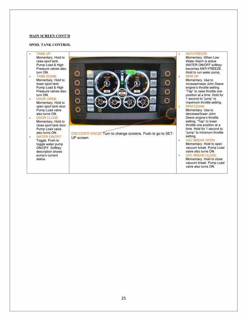
MAIN SCREEN CONT’D
Active Machine Functions bar: The bottom of the screen shows what machine functions are ON:
= work lights ON. Controlled on LIGHTS/AUX screen.
= boom extend valve ON. Controlled on BOOM screen or by remote transmitter.
= strobe light ON. Controlled on LIGHTS/AUX screen
= boom retract valve ON. Controlled on BOOM screen or by remote transmitter.
= auxiliary output #1 ON. Controlled on LIGHTS/AUX screen.
= boom swing clockwise valve ON. Controlled on BOOM screen or by remote transmitter.
= auxiliary output #2 ON. Controlled on LIGHTS/AUX screen.
= boom swing counter clockwise valve ON. Controlled on BOOM screen or by remote transmitter.
= hot box is ON. Controlled on HOT BOX screen if option is enabled.
= boom gate valve open ON. Controlled on BOOM screen or by remote transmitter.
= boom up valve ON. Controlled on BOOM screen or by remote transmitter.
= boom gate valve close ON. Controlled on BOOM screen or by remote transmitter.
= boom down valve ON. Controlled on BOOM screen or by remote transmitter.
= RF remote control transmitter is ON.
Turn Encoder Knob to change screens. Encoder Knob’s label shows which screen will come up when knob is turned in direction of arrows. Turn right = go to LIGHTS screen Push = go to SET-UP screen Turn left = go to ENGINE ERRORS screen
25
MAIN SCREEN CONT’D
SPOIL TANK CONTROL
• TANK UP: Momentary. Hold to raise spoil tank. Pump Load & High Pressure valves also turn ON.
• TANK DOWN: Momentary. Hold to lower spoil tank. Pump Load & High Pressure valves also turn ON.
• DOOR OPEN: Momentary. Hold to open spoil tank door. Pump Load valve also turns ON.
• DOOR CLOSE: Momentary. Hold to close spoil tank door. Pump Load valve also turns ON.
• WATER ON/OFF: Toggle. Push to toggle water pump ON/OFF. Softkey description shows pump’s current status.
ENCODER KNOB: Turn to change screens. Push to go to SET-UP screen.
• ANTI-FREEZE: Momentary. When Low Water Alarm is active WATER ON/OFF softkey becomes ANTI-FREEZE. Hold to run water pump.
• RPM UP: Momentary. Use to increase/raise John Deere engine’s throttle setting. “Tap” to raise throttle one position at a time. Hold for 1 second to “jump” to maximum throttle setting.
• RPM DOWN: Momentary. Use to decrease/lower John Deere engine’s throttle setting. “Tap” to lower throttle one position at a time. Hold for 1 second to “jump” to minimum throttle setting.
• VAC BREAK OPEN: Momentary. Hold to open vacuum break. Pump Load valve also turns ON.
• VAC BREAK CLOSE: Momentary. Hold to close vacuum break. Pump Load valve also turns ON.
26
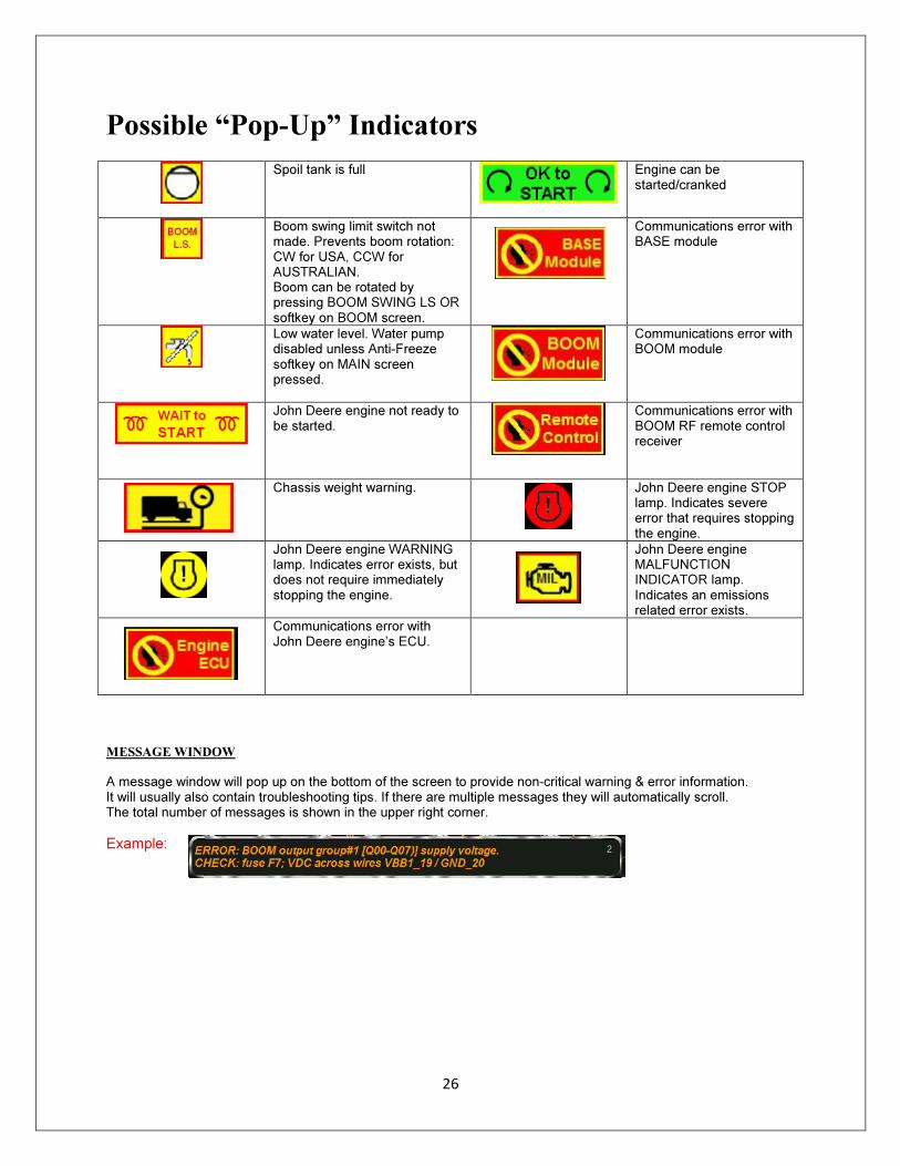
Possible “Pop-Up” Indicators
Spoil tank is full
Engine can be started/cranked
Boom swing limit switch not made. Prevents boom rotation: CW for USA, CCW for AUSTRALIAN. Boom can be rotated by pressing BOOM SWING LS OR softkey on BOOM screen.
Communications error with BASE module
Low water level. Water pump disabled unless Anti-Freeze softkey on MAIN screen pressed.
Communications error with BOOM module
John Deere engine not ready to be started.
Communications error with BOOM RF remote control receiver
Chassis weight warning. John Deere engine STOP lamp. Indicates severe error that requires stopping the engine.
John Deere engine WARNING lamp. Indicates error exists, but does not require immediately stopping the engine.
John Deere engine MALFUNCTION INDICATOR lamp. Indicates an emissions related error exists.
Communications error with John Deere engine’s ECU.
MESSAGE WINDOW
A message window will pop up on the bottom of the screen to provide non-critical warning & error information. It will usually also contain troubleshooting tips. If there are multiple messages they will automatically scroll. The total number of messages is shown in the upper right corner.
Example:
27
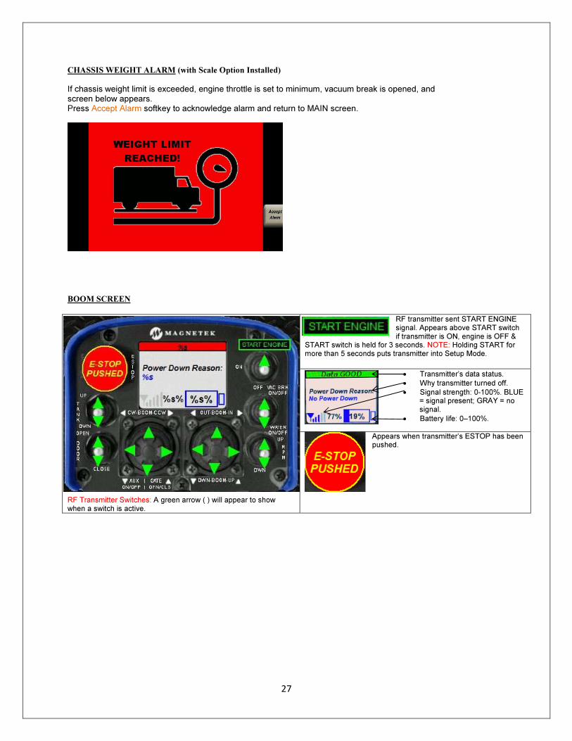
CHASSIS WEIGHT ALARM (with Scale Option Installed)
If chassis weight limit is exceeded, engine throttle is set to minimum, vacuum break is opened, and screen below appears. Press Accept Alarm softkey to acknowledge alarm and return to MAIN screen.
BOOM SCREEN
RF Transmitter Switches: A green arrow ( ) will appear to show when a switch is active.
RF transmitter sent START ENGINE signal. Appears above START switch if transmitter is ON, engine is OFF &
START switch is held for 3 seconds. NOTE: Holding START for more than 5 seconds puts transmitter into Setup Mode.
• Transmitter’s data status. • Why transmitter turned off. • Signal strength: 0-100%. BLUE
= signal present; GRAY = no signal.
• Battery life: 0–100%.
Appears when transmitter’s ESTOP has been pushed.
28
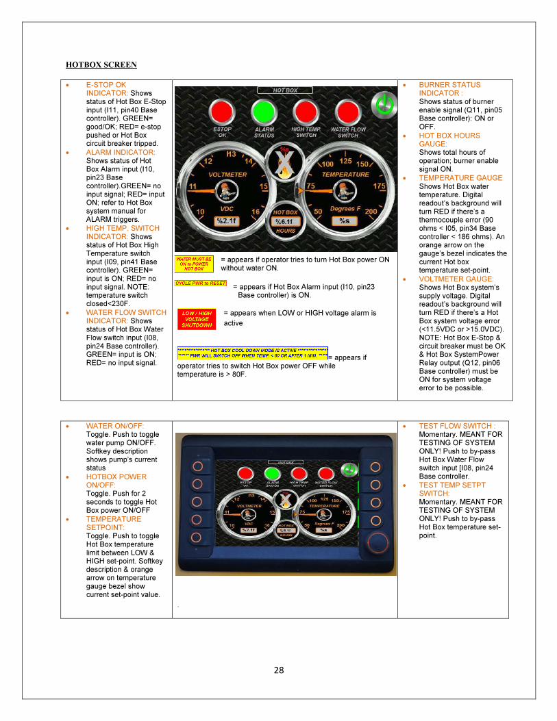
HOTBOX SCREEN
• E-STOP OK INDICATOR: Shows status of Hot Box E-Stop input (I11, pin40 Base controller). GREEN= good/OK; RED= e-stop pushed or Hot Box circuit breaker tripped.
• ALARM INDICATOR: Shows status of Hot Box Alarm input (I10, pin23 Base controller).GREEN= no input signal; RED= input ON; refer to Hot Box system manual for ALARM triggers.
• HIGH TEMP. SWITCH INDICATOR: Shows status of Hot Box High Temperature switch input (I09, pin41 Base controller). GREEN= input is ON; RED= no input signal. NOTE: temperature switch closed<230F.
• WATER FLOW SWITCH INDICATOR: Shows status of Hot Box Water Flow switch input (I08, pin24 Base controller). GREEN= input is ON; RED= no input signal.
= appears if operator tries to turn Hot Box power ON without water ON.
= appears if Hot Box Alarm input (I10, pin23
Base controller) is ON.
= appears when LOW or HIGH voltage alarm is
active.
= appears if operator tries to switch Hot Box power OFF while temperature is > 80F.
• BURNER STATUS INDICATOR : Shows status of burner enable signal (Q11, pin05 Base controller): ON or OFF.
• HOT BOX HOURS GAUGE: Shows total hours of operation; burner enable signal ON.
• TEMPERATURE GAUGE Shows Hot Box water temperature. Digital readout’s background will turn RED if there’s a thermocouple error (90 ohms < I05, pin34 Base controller < 186 ohms). An orange arrow on the gauge’s bezel indicates the current Hot box temperature set-point.
• VOLTMETER GAUGE: Shows Hot Box system’s supply voltage. Digital readout’s background will turn RED if there’s a Hot Box system voltage error (<11.5VDC or >15.0VDC). NOTE: Hot Box E-Stop & circuit breaker must be OK & Hot Box SystemPower Relay output (Q12, pin06 Base controller) must be ON for system voltage error to be possible.
• WATER ON/OFF: Toggle. Push to toggle water pump ON/OFF. Softkey description shows pump’s current status
• HOTBOX POWER ON/OFF: Toggle. Push for 2 seconds to toggle Hot Box power ON/OFF
• TEMPERATURE SETPOINT: Toggle. Push to toggle Hot Box temperature limit between LOW & HIGH set-point. Softkey description & orange arrow on temperature gauge bezel show current set-point value.
.
• TEST FLOW SWITCH : Momentary. MEANT FOR TESTING OF SYSTEM ONLY! Push to by-pass Hot Box Water Flow switch input [I08, pin24 Base controller.
• TEST TEMP SETPT SWITCH: Momentary. MEANT FOR TESTING OF SYSTEM ONLY! Push to by-pass Hot Box temperature set-point.
29
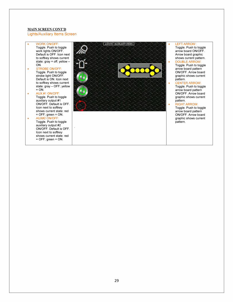
MAIN SCREEN CONT’D
Lights/Auxiliary Items Screen
• WORK ON/OFF: Toggle. Push to toggle work lights ON/OFF. Default is OFF. Icon next to softkey shows current state: gray = off; yellow – ON.
• STROBE ON/OFF: Toggle. Push to toggle strobe light ON/OFF. Default is ON. Icon next to softkey shows current state: gray – OFF; yellow = ON.
• AUX.#1 ON/OFF: Toggle. Push to toggle auxiliary output #1 ON/OFF. Default is OFF. Icon next to softkey shows current state: red = OFF; green = ON.
• AUX#2 ON/OFF: Toggle. Push to toggle auxiliary output #2 ON/OFF. Default is OFF. Icon next to softkey shows current state: red = OFF; green = ON.
.
• LEFT ARROW : Toggle. Push to toggle arrow board ON/OFF. Arrow board graphic shows current pattern.
• DOUBLE ARROW: Toggle. Push to toggle arrow board pattern ON/OFF. Arrow board graphic shows current pattern.
• CENTER ARROW: Toggle. Push to toggle arrow board pattern ON/OFF. Arrow board graphic shows current pattern.
• RIGHT ARROW: Toggle. Push to toggle arrow board pattern ON/OFF. Arrow board graphic shows current pattern.
30
Operation of Machine
PRE-OPERATING INSTRUCTIONS
Contact the local safe dig service to determine if you can begin. Before operating the vacuum system on a job site, the operator should be trained in vacuum excavation and cable locating. All sections of the manual should be read and understood. Prior to excavation, the operator should:
1. Check all fluid levels in the engine, vacuum pump, and water pump. 2. Check all vacuum hoses and tools for blockages and damage. 3. Check all filters and clean or replace as necessary.
CAUTION: DO NOT OPERATE WITHOUT FILTER SYSTEM INTACT.
4. Inspect all safety equipment, boots, gloves, etc. for wear and damage. Replace if necessary. 5. Check any utility maps for locations of buried utilities that need to be exposed. 6. If excavations are to be conducted near or on roadways, make sure local authorities are contacted for
regulations regarding traffic control and safety. 7. Know the contents of the material you are excavating or remediating. 8. Know the local regulations for disposing of liquid material and/or mud. 9. Have a place or a plan for the disposal of the material taken into the tank
WARNING: DO NOT VACUUM HAZARDOUS OR FLAMMABLE MATERIAL WITH THIS
SYSTEM. CONSULT FEDERAL, STATE, AND LOCAL REGULATIONS REGARDING
CLASSIFICATIONS OF HAZARDOUS MATERIAL.
STARTING THE DIESEL ENGINE
WARNING: MOVING PARTS. DEATH OR SERIOUS INJURY MAY RESULT. DO NOT
OPERATE WITHOUT GUARDS IN PLACE.
1. Open the inlet gate valve or boom gate valve in Spoil Tank. 2. Rotate key clockwise to ACC position. 3. LCD screen will come on. 4. When the screen states OK to start rotate key to the start position. 5. Let engine warm up until the message “warming engine” disappears.
31
COLD WEATHER STARTING: Refer to engine maintenance section for proper oil requirements before operating in cold temperature conditions. IMPORTANT: Do not use aerosol Starting Fluids.
SHUTDOWN PROCEDURE 1. Reduce engine speed to idle. 2. Shut off the engine and remove the key. 3. Relieve water pressure from the Water Assisted Tools by squeezing trigger
and disconnect tool from hose.
IMPORTANT: Never use main power disconnect switch to stop engine.
JUMP STARTING
WARNING: FLAMMABLE FUMES. FUMES MAY EXPLODE OR CATCH FIRE. KEEP AWAY
SPARKS AND OPEN FLAME. BATTERY ACID CAN BURN SKIN AND EYES. PROTECT FACE,
HANDS AND BODY WHEN SERVICING.
Use only a 12 volt system for jump starting. Use only an approved set of jumper cables. Avoid inadvertent contact with cables and surrounding components.
1. Connect first RED clamp to POSITIVE (+) terminal of discharged battery. 2. Connect second RED clamp to POSITIVE (+) terminal of charged battery. 3. Connect first BLACK clamp to machine frame of the machine with the charged battery. 4. Connect second BLACK clamp to machine frame of the machine with the discharged battery.
CONNECTING VACUUM HOSES AND TOOLING
1. Remove vacuum hose from storage. 2. Install male hose end into female hose end on tank inlet port and lock the cam levers. If there is a boom on
the machine, attach the male hose end into the female hose end on the end of the boom and lock the cam levers.
3. Attach additional vacuum hoses as needed for distance. 4. Remove the necessary tooling from the tool storage. 5. Attach necessary tooling onto the end of the vacuum hose and lock the cam levers.
32
JOB SITE PREPARATIONS
When pot-holing for non-destructive exposure of underground utilities prior to excavating, trenching or boring, coordinate with all local utilities and mapping services. The area of the proposed excavation should be marked. The one call service should have been contacted and the area marked or cleared. Any underground plant owners not participating in the one call system should be notified and have their underground facilities marked. Use a pipe and cable locator to do a search of the area to be excavated to determine if any unmarked facilities exist. This may also help determine a more precise location of any marked facilities. Consult area utility maps or seek advice on nonmetallic pipes such as sewer or storm water lines that may not be marked.
WARNING: WHEN EXPOSING UTILITY LINES FOR AVOIDANCE IN A DIGGING
APPLICATION, VERIFY THAT THE EXPOSED LINE IS THE CORRECT LINE.
EXCAVATIONS MAY CONTAIN MULTIPLE LINES OR ABANDONED LINES, AS
WELL AS THE LINE TO BE EXPOSED.
Establish and maintain traffic control procedures to keep the vacuum crew safe during the operation. Traffic cones or barricades should be used to establish a “safe” area around the vacuum work site. When working in low light conditions, use work lights to illuminate the area and provide visibility. Determine the proper safety equipment to wear. When doing vacuum slurry excavation proper safety equipment should be worn consisting of eye protection, high visual clothing or vest, hard hat, gloves, ear protection and steel cap work boots. When doing vacuum slurry excavation around energized power lines dielectric insulated boots should be worn. This is to protect the operator from becoming shocked or electrocuted if the reduction tool comes into accidental contact with a leaking power line. Electric boots should be maintained by following the manufacturer’s specific instructions. Read and follow those directions carefully. They are contained in section 5 of this manual. Replace worn out or torn boots. Always wear personal protective equipment including hard hat, reflective vest, work boots and safety glasses. Ear protection should also be used when operating the vacuum system.
WARNING: DO NOT WEAR LOOSE FITTING CLOTHING OR LONG HAIR.
THEY CAN BE SUCKED INTO THE VACUUM HOSE AND CAUSE SERIOUS
INJURY .
Keep bystanders and spectators away from the vacuum system and work site. Loose flying debris can injure or blind bystanders. Allow only authorized personnel with proper safety equipment in the work area.
33
POTHOLING EXCAVATION (With Water Only)
Potholing excavation is achieved by use of the reduction tool or rotary lance and vacuum tool. This tool combines the operations of “reducing” and “removing” material from the ground. The end result being a small pothole that allows for the visual identification of buried utilities. In the reduction step, high pressure water is used to reduce the soil to a size small enough to be vacuumed. It is important to let the water do the “reducing” of the soil so as not to damage the utility being exposed with the end of the tool. In the removing step the “reduced” soil is vacuumed out of the excavated pothole. To begin the job site operation:
1. Position the vacuum unit as close to the area to be excavated as possible. 2. Set the parking brake and chock wheels. (Trailer units must remain hooked to the towing vehicle.) 3. Start the power unit and allow the engine to warm up. (Refer to the Start-Up Procedure in this section of the
manual.) 4. Place necessary traffic control measures. 5. Use proper personal safety protection equipment, including electric boots when necessary. 6. When preparing to pothole in a grassy area, use a spade or other appropriate digging tool to loosen and
remove the grass plug over the area to be excavated. If pot-holing under asphalt or concrete, use a hydraulic or air operated breaker or saw to remove the top material and expose the earth.
7. Connect the water line to the high pressure rotary lance. 8. Attach the vacuum hose to the suction tool. 9. Attach the vacuum hose to the inlet port on the spoil tank. If additional hose is needed, attach using the cam
lock fittings provided on the hose ends. Short hose lengths are recommended to reduce vacuum hose clogging. If the vacuum hose is connected to the spoil tank and the engine is running with the selector lever in vacuum, the suction tool will be vacuuming. To stop the vacuuming, move the selector to the neutral position.
DANGER: SUFFOCATION HAZARD; WILL CAUSE SERIOUS INJURY OR
DEATH. KEEP HOSES AND VACUUM TOOLS AWAY FROM FACE AND BODY.
10. Open the hose reel ball valve. 11. Position the rotary lance vertically at the desired potholing location.(Never point the rotary lance upward and
pull the trigger on the tool. This will cause the rotary nozzle to become damaged internally) 12. Squeeze the rotary lance trigger lever and move the rotary lance in a semi-circular motion with the handle.
This will allow the rotary nozzle to excavate a cylindrical hole in the ground. 13. After the hole is started place the suction tool over the area you are potholing. This will vacuum all material
into the debris tank.
WARNING: FLYING OBJECTS CAN CAUSE SERIOUS INJURY OR
BLINDNESS. WEAR EYE PROTECTION.
WARNING: HIGH PRESSURE WATER CAN CAUSE SERIOUS INJURY.
WEAR PROTECTIVE CLOTHING AND DO NOT POINT HIGH PRESSURE
WATER TOOLS TOWARD BODY PARTS.
14. As the reduction step continues to expose the utility, be aware of changes in soil conditions. A soft area that
allows faster penetration will usually mean that the excavated hole is approaching the utility. When resistance is encountered, stop. Remove the tooling from the pothole and identify the utility or obstruction.
15. If the utility cannot be completely exposed from one hole, the hole size must be enlarged to allow observation of the complete utility. It is important to be able to observe the entire utility to determine its size.
16. The spoil tank is equipped with a “full tank” engine shut down sensor for fluid applications. When the fluid level in the tank reaches capacity, a sensor will automatically shut down the engine. This prevents overfilling the tank and sending fluid into the filtration system. When the vacuum system automatically shuts down, empty spoil tank. (Refer to the section titled Emptying the Spoil Tank.) (There is a secondary ball and cage vacuum shutoff as well)
17. When finished potholing, close the hose reel ball valve. If the spoil tank is, the engine will shut down automatically. If the tank is not full, shut down engine and remove key. Squeeze the rotary lance trigger lever to release trapped water pressure prior to unhooking. All tools and hoses should be securely stored before traveling to the spoil disposal site.
34
VACUUM EXCAVATION
Vacuum excavation is the processes of removing material whether wet or dry by a powerful air stream. This is accomplished use of the vacuum tool.
WARNING: DO NOT VACUUM HAZARDOUS MATERIAL WITH THIS SYSTEM.
CONSULT FEDERAL, STATE, AND LOCAL REGULATIONS REGARDING
CLASSIFICATIONS OF HAZARDOUS MATERIAL.
To begin the job site operation: 1. Position the vacuum unit as close to the area to be excavated as possible. 2. Set the parking brake and chock wheels. 3. Place necessary traffic control measures. 4. Start the power unit and allow the engine to warm up. (Refer to the Start-up Procedure in this section of
the manual.) 5. Use proper personal protection equipment. 6. Attach the vacuum hose to the vacuum tool. 7. Attach the vacuum hose to the inlet port on the spoil tank. If additional hose is needed, attach using the
cam lock fittings provided on the hose ends. Short hose lengths are recommended to reduce vacuum hose clogging. If the vacuum hose is connected to the spoil tank and the engine is running with the selector in the vacuum position, the vacuum tool will be vacuuming. To stop the vacuuming, move the selector to the neutral position.
DANGER: SUFFOCATION HAZARD WILL CAUSE SERIOUS INJURY OR
DEATH. KEEP HOSES AND VACUUM TOOLS AWAY FROM FACE AND BODY.
8. When vacuuming fluids, it is more efficient to turn the liquid into an aerosol by not completely submerging the vacuum tool in the fluid. By keeping part of the vacuum tool out of the fluid, the airflow through the vacuum tube will move the material quicker to the spoil tank. This technique is also effective when vacuuming deep vertical distances.
9. The spoil tank is equipped with a “full tank” engine shut down sensor for fluid applications. When the fluid level in the tank reaches capacity, a sensor will automatically shut down the engine. This prevents overfilling the tank and sending fluid into the filtration system. When the vacuum system automatically shuts down, empty spoil tank. (Refer to the section titled Emptying the Spoil Tank.)
10. When vacuuming dry materials, the “full tank” shutdown sensor will not work. Vacuuming should be stopped when the debris level in the spoil tank has reached the sight glass or when debris can be heard circulating in the cyclone separator.
11. When finished, the engine should be shut down if not automatically shut down and the key removed. All tools and hoses should be securely stored before traveling to the spoil disposal site.
35
EMPTYING THE SPOIL TANK - HYDRAULIC LOCKING DOOR
Emptying the vacuum spoil tank presents several hazards that the operator should be aware of.
DANGER: CRUSHING WEIGHT. SPOIL AND DOOR WILL CAUSE DEATH AND SERIOUS
INJURY. UNLOCK DOOR ONLY UNDER VACUUM. STAY AWAY FROM DOOR WHEN
DUMPING.
DANGER: CRUSHING WEGHT. ROLLING OR TILTING UNIT WILL CAUSE DEATH OR
SERIOUS INJURY. CHOCK TIRES AND APPLY PARKING BRAKE BEFORE OPERATING OR
SERVICING. DO NOT OPERATE OR SERVICE UNLESS ATTACHED TO VEHICLE.
Before beginning vacuum operations, a plan and site for disposing of the spoil in the tank should be established.
1. Before arriving at the disposal site, verify the water tank has an adequate level for cleanup if equipped. 2. After arriving at the disposal site, set the parking brake and chock the wheels. 3. Open the inlet port. 4. It is recommended that liquids be drained from the tank, prior to raising the tank. Use the gate valve located
in the bottom of the door to drain excess liquids. 5. At the operator’s console, turn the vacuum tank full override switch on. Override is only required when the
spoil tank is full. 6. Start the engine. 7. Press and hold the door open switch . The door will unlock and open. 8. Once the door is open, press and hold the tank raise switch. 9. Once the tank has been emptied, it may be cleaned while in the raised position. Units not cleaned after
dumping should have the door seal and mating flange wiped clean of debris that may damage the seal when sealing the door.
10. Open the cyclone door and remove debris. Close the cyclone door. 11. Lower the tank and close the door. Turn the engine off and remove the key. 12. The air filter should be cleaned once a day. Open the air filter door and inspect the air filter element. If the air
filter element is dirty, remove and clean with low pressure water. The air filter may be cleaned with the spray wand. The cleaned air filter may be installed after it has been cleaned and allowed to dry. Damaged air filters should be replaced immediately. The unit should not be operated without the air filter element; damage to the blower will result.
13. Secure all tools and hoses prior to leaving the spoil disposal site.
36
TANK CLEANING
DANGER: CRUSHING WEGHT. ROLLING OR TILTING UNIT WILL CAUSE
DEATH OR SERIOUS INJURY. CHOCK TIRES AND APPLY PARKING BRAKE
BEFORE OPERATING OR SERVICING. DO NOT OPERATE OR SERVICE
UNLESS ATTACHED TO VEHICLE.
Units with spoil in the tank should follow the instructions for emptying the spoil tank before proceeding.
1. Start the engine. 2. With the tank empty and the door open, raise the tank. (Operator must install the door safety pin while
working under the raised door.) 3. Attach the spray wand to the water hose and open the supply ball valve. 4. Run the engine at high speed.
WARNING: HIGH PRESSURE WATER CAN CAUSE SERIOUS INJURY. WEAR PROTECTIVE
CLOTHING AND DO NOT POINT HIGH PRESSURE WATER TOOLS TOWARD BODY PARTS.
6. The unit may now be cleaned with the spray wand and automatic tank cleanout. Care should be taken when cleaning the door seal with the spray wand. The door seal may be damaged if the spray wand is held in close proximity to the door seal or sprayed with high pressure.
7. The automatic tank cleanout is operated by opening the tank cleanout ball valve. Material will be washed out of the spoil tank. Close the tank cleanout valve when the tank is adequately clean.
8. Close the hose reel ball valve. 9. Release trapped water pressure in the water hose by squeezing the trigger on the spray wand gun. 10. Lower the tank and remove the door safety pin. Close the door. Run the engine at low. Turn the key to the
off position and remove the key. 11. Secure all tools and hoses prior to departing.
TOOL AND HOSE CLEANING
All tools and hoses should be cleaned prior to storage. Debris build up on the tools and hoses will reduce performance .
1. Connect the dirty tool and hoses to the spoil tank inlet. 2. Connect the spray wand to the high pressure water hose. 3. Start the engine and operate at high speed. 4. Open the hose reel ball valve.
WARNING: HIGH PRESSURE WATER CAN CAUSE SERIOUS INJURY. WEAR PROTECTIVE
CLOTHING AND DO NOT POINT HIGH PRESSURE WATER TOOLS TOWARD BODY PARTS.
5. Reduce the pressure on the spray wand to its lowest setting. 6. Use the spray wand to wash off the tool and hose. Material on the inside of the tool and hose will be
vacuumed into the spoil tank. 7. When finished, close the hose reel ball valve. 8. Release trapped water pressure in the water hose by squeezing the trigger on the spray wand gun. 9. Run the engine at low. Turn the engine off and remove the key. 10. Secure all tools and hose prior to departing.
37
WATER SYSTEM FREEZE PROTECTION
All vacuum systems supplied with a water system should be filled with antifreeze if being stored or transported in freezing conditions. Systems not filled with antifreeze are susceptible to freezing water system damage. UNITS SUPPLIED WITH WATER SYSTEMS ONLY
1. Fully drain the water system by opening the drain valve. 2. Remove the drain plug from the strainer and remove excess water from the system. 3. Reinsert the drain plug. 4. Verify no tools are connected to the high pressure water hose. 5. Place the end of the high pressure water hose in the water tank. 6. Close the supply ball valve at the wire strainer. 7. Fill the antifreeze tank and open the antifreeze ball valve.
CAUTION: DO NOT LET THE WATER PUMP RUN DRY. MAKE SURE A
LEVEL OF ANTIFREEZE IS VISIBLE AT ALL TIMES. RUNNING THE WATER
PUMP DRY WILL RESULT IN WATER PUMP DAMAGE.
8. Open the spoil tank inlet and start the engine. Operate the engine at low speed during Anti-freezing. 9. Open the hose reel ball valve. 10. Press and hold the antifreeze soft button on the LCD screen. 11. Watch the flow coming out of the end of the water hose. Release the antifreeze button as soon as antifreeze
is detected coming out of the hose. Remember not to let the antifreeze in the tank to run completely out. 12. Close the hose reel ball valve. 13. Open the gate valve in the tank door and open the tank cleanout ball valve. 14. Press and hold the antifreeze button. 15. Watch the flow coming out the tank door valve. Release the antifreeze button as soon as antifreeze is
detected. Close the gate valve in the tank door and close the tank cleanout valve. 16. Press and hold the antifreeze switch momentarily. This will push antifreeze through the bypass side of the
unloader. 17. Open the water tank ball valve allowing antifreeze to flow into the suction plumping. Close the antifreeze ball
valve. 18. Turn the engine off. The system is antifreezed.
REMOVING DEBRIS FROM SPOIL TANK
1. Attach hose to lower gate valve to transfer spoil material from tank to designated ares. 2. Make sure flow control valve is in neutral. 3. Start the unit and put the unit in high throttle. 4. Move the control flow valve to pressure. 5. Open the lower gate valve with hose attached and pointed in safe direction. 6. Place the flow valve back into neutral. 7. Close bottom gate valve and turn machine off. 8. At this point operator can either go back to work or remove solid waste from the tank.
BOOM
1. Remove the remote from the curbside door. 2. Start the unit and switch throttle to high. 3. Using the remote, raise the boom so it clears all obstruction in the travel path. 4. Use the remote to unlock the pin on manual boom and grab the rope to swing the boom into position. 5. Let go of button to lock pin into place. 6. (Hydraulic Boom) Use the remote to move boom into desired position. 7. Using the remote lower the boom so the hose handle can be easily removed and first section of hose can
easily be attached. 8. Attach first section of hose then raise the boom to attach second section of hose. Attach hose handle to the
lowest section of hose at an easy operating position and attach the remote for easy operation. 9. At this point boom is ready for operational use.
38
CLEAN UP
1. Remove hose handle and remote and then remove first section of hose. Lower the boom to a position to
easily remove second section of hose. 2. Retract boom and Raise boom to clear all obstruction in travel path. Unlock pin and swing boom back into
position on top of bracket. 3. Clean hoses and place them into designated storage space. 4. Lower engine throttle and turn off engine. Store the remote back into place inside door.
39
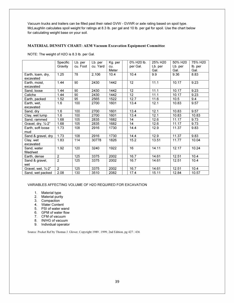
Vacuum trucks and trailers can be filled past their rated GVW - GVWR or axle rating based on spoil type.
McLaughlin calculates spoil weight for ratings at 8.3 lb. per gal and 10 lb. per gal for spoil. Use the chart below
for calculating weight base on your soil.
MATERIAL DENSITY CHART: AEM Vacuum Excavation Equipment Committee
NOTE: The weight of H2O is 8.3 lb. per Gal.
Specific Gravity
Lb. per cu. Foot
Lb. per cu. Yard
Kg. per cu. Meter
0% H20 lb. per Gal.
25% H20 Lb. per Gal.
50% H20 Lb. per Gal.
75% H20 lb. per Gal.
Earth, loam, dry, excavated
1.25 78 2,106 10.4 10.4 9.9 9.36 8.83
Earth, moist, excavated
1.44 90 2430 1442 12 11.1 10.17 9.23
Sand, loose 1.44 90 2430 1442 12 11.1 10.17 9.23
Caliche 1.44 90 2430 1442 12 11.1 10.17 9.23
Earth, packed 1.52 95 2565 1522 12.7 11.6 10.5 9.4
Earth, wet, excavated
1.6 100 2700 1601 13.4 12.1 10.83 9.57
Sand, dry 1.6 100 2700 1601 13.4 12.1 10.83 9.57
Clay, wet lump 1.6 100 2700 1601 13.4 12.1 10.83 10.83
Sand, rammed 1.68 105 2835 1682 14 12.6 11.17 9.73
Gravel, dry, ¼-2” 1.68 105 2835 1682 14 12.6 11.17 9.73
Earth, soft loose mud
1.73 108 2916 1730 14.4 12.9 11.37 9.83
Sand & gravel, dry 1.73 108 2916 1730 14.4 12.9 11.37 9.83
Clay, wet excavated
1.83 114 30778 1826 15.2 13.51 11.77 10.04
Sand, water filled/wet
1.92 120 3240 1922 16 14.11 12.17 10.24
Earth, dense 2 125 3375 2002 16.7 14.61 12.51 10.4
Sand & gravel, wet
2 125 3375 2002 16.7 14.61 12.51 10.4
Gravel, wet, ¼-2” 2 125 3375 2002 16.7 14.61 12.51 10.4
Sand, wet packed 2.08 130 3510 2082 17.4 15.11 12.84 10.57
VARIABLES AFFECTING VOLUME OF H2O REQUIRED FOR EXCAVATION
1. Material type 2. Material purity 3. Compaction 4. Water Content 5. PSI of water wand 6. GPM of water flow 7. CFM of vacuum 8. IN/HG of vacuum 9. Individual operator
Source: Pocket Ref by Thomas J. Glover, Copyright 1989"1999, 2nd Edition, pg 427"436
40
WARRANTY
RETURN GOODS POLICY
LIMITED WARRANTY The Manufacturer warrants its products to be free from defects in material and workmanship for a period of twelve months from the date of shipment from the factory. The Manufacturer shall not be responsible for any damage resulting to or caused by its products by reason of installation, improper storage, unauthorized service, alteration of the products, neglect or abuse, or use of the product in a manner inconsistent with its design. This warranty does not extend to any component parts not manufactured by Manufacturer; however, Manufacturer’s warranty herein shall not limit any warranties made by manufacturers of component parts which extend to Buyer. Claims for defects in material and workmanship shall be made in writing to Manufacturer within ten days of discovery of defect. Manufacturer may either send a service representative or have the product returned to its factory at Buyer’s expense for inspection. Upon notification of defect, Manufacturer will issue a return goods authorization number to Buyer. The return goods authorization number must accompany the product returned. If judged by the Manufacturer to be defective in material or workmanship, the product will be replaced or repaired at the option of the manufacturer, free from all charges except authorized transportation. Buyer shall be responsible for all maintenance services consisting of lubrication and cleaning of equipment, replacing expandable parts, making minor adjustments, and performing operating checks, all in accordance with procedures outlined in Manufacturer’s maintenance literature. THE FOREGOING WARRANTY IS IN LIEU OF ALL OTHER WARRANTIES AND NO REPRESENTATIONS, GUARANTEES, OR WARRANTIES, EXPRESS OR IMPLIED, (INCLUDING BUT NOT LIMITED TO A WARRANTY OF MERCHANTABILITY OR FITNESS FOR A PARTICULAR PURPOSE), ARE MADE BY THE MANUFACTURER IN CONNECTION WITH THE MANUFACTURE OR SALE OF ITS PRODUCTS. NO EMPLOYEE, DISTRIBUTOR, OR REPRESENTATIVE IS AUTHORIZED TO CHANGE THIS WARRANTY ON BEHALF OF MANUFACTURER THE REMEDIES OF BUYER SET FORTH HEREIN ARE EXCLUSIVE AND ARE IN LIEU OF ALL OTHER REMEDIES. THE LIABILITY OF MANUFACTURER WHETHER IN CONTRACT, TORT, UNDER ANY WARRANTY, OR OTHERWISE SHALL NOT EXTEND BEYOND ITS OBLIGATION TO REPAIR OR REPLACE, AT ITS OPTION ANY PRODUCT OR PART FOUND BY MANUFACTURER TO BE DEFECTIVE IN MATERIAL OR WORKMANSHIP. MANUFACTURER SHALL NOT BE LIABLE FOR COST OF INSTALLATION AND/OR REMOVAL OR BE RESPONSIBLE FOR DIRECT, INDIRECT, SPECIAL OR CONSEQUENTIAL DAMAGES OF ANY NATURE.
GENERAL RETURNS OF MERCHANDISE
1. All returns must be pre-authorized A. Please call our parts department for an RGA number B. Please include RGA number on the outside of box C. Include any required paper work or special instructions D. Items returned without an RGA number will not be accepted
2. All returns are subject to a 20% restock charge. 3. Special items are non-returnable
A. Non-stock parts B. Custom parts C. If you are unsure about a parts status when ordering, ask your McLaughlin representative D. If the item fits on of the above conditions.
4. Items must be returned within thirty days of original order date. 5. Items not returned within 30 days from the date of RGA is issued will not be accepted.
6. The item(s) must be in new condition. Used item(s) are not returnable.
Recommended