1
(PENDING)
VISIT OUR WEBSITE SIGMACONTROLS.COM
700 SERIES ‘TPC’ TRIPLEX PUMP
CONTROLLER INSTRUCTION MANUAL
700SERIESTPCMANUAL011411
2
TABLE OF CONTENTS
INTRODUCTION………………………………………… 3
Ordering Information
Specifications
Features
WIRING…………………………………………………… 7
Dwg # 10-298
Analog Input
Analog Output
Digital Input
Digital Output
PROGRAMMING AND INITIAL SETUP……………... 8
Input Range Selection
Terminal Block Detail
Initial Setup & Programming
Overview/Key Description
TROUBLESHOOTING & MAINTENANCE ………….. 19
DIAGNOSTICS…………………………………………… 20
PROGRAMMING RECORD SHEET…………………...
22
MODBUS® PLUG & CABLE
DETAIL…………………...
23
WARRANTY……………………………………………… 25

3
INTRODUCTION:
The Sigma 700 Series Triplex Pump Controller is a state of the art microprocessor based, user
configurable instrument for the monitoring and control of three (3) constant speed or (3) variable speed
driven pumps.
The 700 TPC Series performs all of the functions found in a full size control panel.
� Displays level in alpha and numeric forms � Displays pump run status � Allows full user selection of all system variables � Monitors critical alarms (motor overtemperature, etc.) � Monitors non critical alarms (seal leak, etc.) � Monitors hand off auto selection switch position � Monitors pump (VFD) ‘run’ feedback � Provides relay outputs for pump control, level alarm, and general alarm. � Provides 4/20MA output for VFD speed setting, proportional control, or retransmission. � Continuous sensor monitor with general alarm output � Visual alarms � Allows simulation’ of level to exercise pumps or verify operation � Provides PID control and calculated flow (optional). � Available in ¼ DIN panel mount or Nema 4X enclosures (optional)
ORDERING INFORMATION:
� 1/4 DIN Case Sigma 700 Series TPC
� Wall Mount Nema 4X Sigma 700 Series-TPC-N4X
SPECIFICATIONS:
� ANALOG INPUT (1 ea.) Analog, 4/20MA isolated with common negative, +-0.1% accuracy.
� DIGITAL INPUTS (8 ea.) Digital 10-30V DC (Grounding)
� ANALOG OUTPUT: (1 ea.) Analog, with common negative 4/20MA.
� RELAY OUTPUTS: (4 ea.) SPDT, Form ‘C’ 5A Relay
� DISPLAY: LCD, 2 line Alphanumeric, Backlit.
� ALARM RESET/SILENCE INPUT

4
� LOOP POWER: 24VDC regulated output, 100MA max. (with 110VAC option).
� 3 USER KEYS: Up, Down, Enter
� ACCURACY: 0.1% of calibrated span
� LOCKOUT: User password, user configurable
� INPUT IMPEDANCE: Voltage 100K, current 100 OHMS
� POWER: 24VDC, (110VAC optional)
� ENVIRONMENTAL: Operating, 0-65° C
Storage, -40° -80° C
R.H., 0-90% non condensing
� ENCLOSURE: ¼ DIN, ABS plastic 96 X 96 X 110MM or Nema 4X wall mount 12 x 8 x 8 inches
� FRONT PANEL: Gasketed Nema 4X
� ACCESS: (DIN CASE) Chassis & boards remove from front of case.
� TERMINAL STRIP: (24) Removable for ease of wiring 28 – 16 AWG
� CONNECTIONS: Removable screw terminal blocks 28 – 16 AWG wire. (27 with 110VAC option)
� CONTROL OUTPUTS: 4 relay outputs, user programmable, SPDT Form ‘C’ relays 5 AMP.
� CPU Activity Monitor
� PROGRAMMING: Menu based, all parameters and setpoints are user configurable via menu prompts and user keys.
The preconfigured screens and ‘pull down’ sub menus with English prompts assures rapid setup
and commissioning.

5
� 1 YEAR WARRANTY
� OPTIONS: Expansion cards, networking
� MODBUS
® Master/Slave
Network allows multiple units to be connected together for distributed applications or remote
monitoring SCADA applications.
� EXPANSION CARDS: Significant expansion is possible via additional control boards and ‘MODBUS
®’ networking.
FEATURES:
� Microprocessor Based � LCD Display � 3 Function Keys � Isolated 24VDC Sensor Power (with 110VAC option) � 4/20MA, Programmable input � 1 Analog Input � 1 Analog Outputs � 8 Digital Inputs � 4 Form ‘C’ Relay Outputs � Fully User Programmable in English � 2 Ea. RS485 Ports (Programming and SCADA) MODBUS® Master/Slave. � CPU Activity Monitor
OPTIONAL I/O CARD
Adds:--
� 1 ea. 4/20MA input and output � 8 ea. programmable digital inputs/outputs � Digital barometer � Bubbler pressure sensor

6
WIRING DETAIL
� Inputs, see Dwg # 10-298 � Outputs, see Dwg # 10-298
CAUTION
! All electrical wiring must be in accordance with all local state and national
codes that apply.
Do not exceed the rated current of the D.C. power supply (100MA) or the form
’C’ relay outputs (5A/240VAC resistive).
WARNING
Hazardous voltages are present within the enclosure. Installation or service
should only be carried out by trained personnel.

7

8
PROGRAMMING & SETUP
Review Screens
The 700 Series TPC utilizes ‘plain English’ menu driven screens which are sequential and intuitive.
When the unit powers up, the startup screen will appear as follows:
After the initial screens have appeared, the unit will show the ‘MAIN SCREEN’.
NOTE: The lower line in the ‘Main’ screen can show multiple process related information.
Press the �������� buttons to scroll to the following information:
Σ SC510-M © 2010 by
SIGMA CONTROLS V3.7
Software Version #
SIGMA CONTROLS, INC.
700 TPC V1.2 SLAVE
Identifies the unit as
programmed for MODBUS®
Slave function
10.0 FEET WC
Engineering units and
current process value. CPU Status Monitor
10.0 Feet
#2 Run
10.0 Feet
Ma Out 13.00
10.0 Feet
ETM 1 1 (HR)
10.0 Feet
1726 GPM Rate Calc
16.00 Feet
4576 Total
10.0 Feet
ETM2 110 HR
10.0 Feet
High Level Alarm
�

9
PROGRAMMING SCREENS
From the Main Menu, Press the � button to access the Password Screen:
.
Use the �� buttons to enter the preprogrammed password, then press � to advance to the Menu Screens. Use the �� buttons to advance to the ‘Scaling’ screen.
Enter the Scaling Menu by pressing the � button and advance to:--
Press the � button to select the number of decimal points desired: .0, .00, .000 or 0 (none), then press � to advance to the Analog Input screen.
Use the �� buttons to select the process value that will be displayed when the input is 4.00MA. Example shows that .00 will be displayed at 4.00MA input. Press � to advance to Analog Input High Screen.
Use the �� buttons as before to select a value to be displayed when the input is 20.00MA.
Press the � button to advance to the Analog Output Low Screen.
Enter Password
0
XXX Menu Selection XXX
SCALING
Locate Decimal Point
.0
Analog Input Low
.00 = 4.00MA
Analog Input High
144.0 = 20.00MA
10
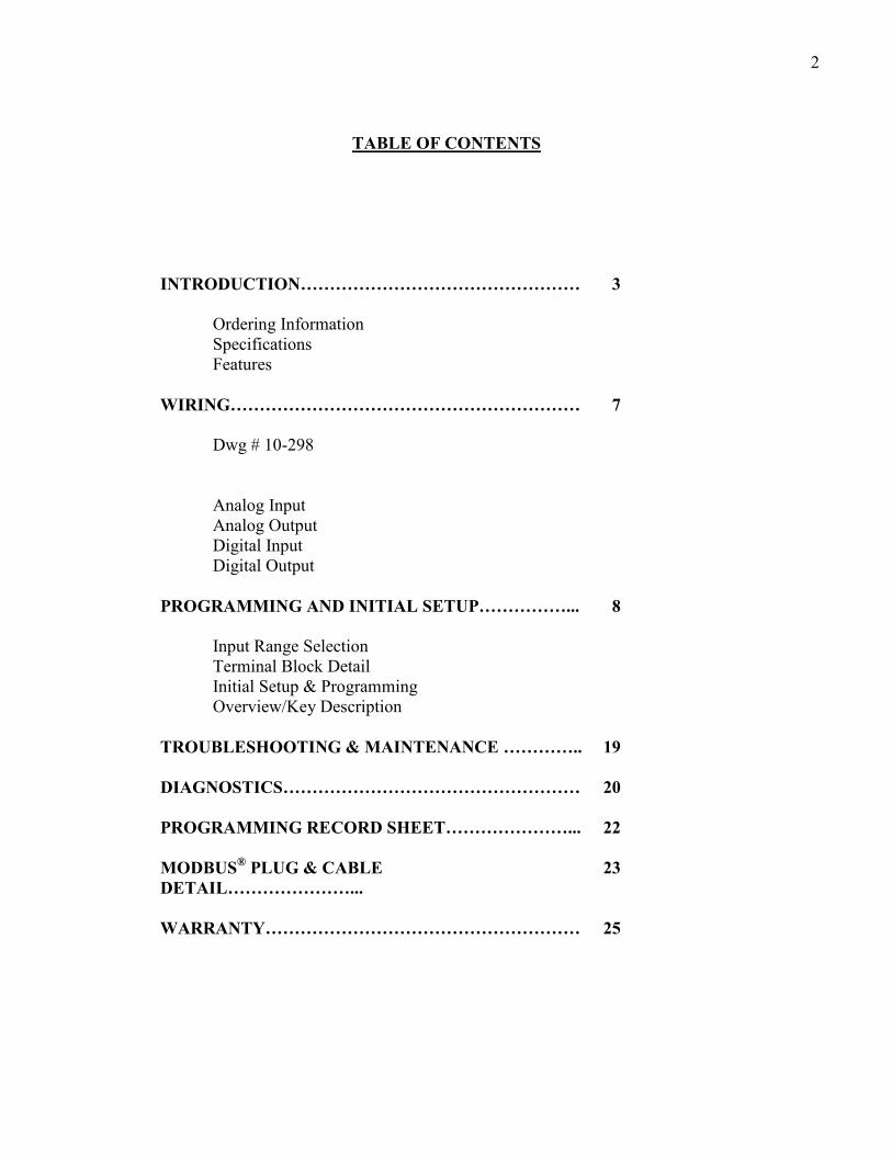
Use �� buttons to select a process value to output 4.00MA then � to advance to the Analog Output High Screen. and select the desired value.
This completes the ‘Scaling’ section. Press � to save any changed values and return to the ‘Main Menu’ Screen. As previously described, enter the MENU selection and select the ‘SETPOINTS’ menu, where
process setpoints are entered. The first screen is the Lead On Setpoint selection.
Press � to advance to the:
Press � to advance to the:--
Press � to advance to the:--
Analog Output Low
.0 = 4.00MA
Analog Output High
144.0 = 20.00MA
Lead On Setpoint
80.0
This is the point at which
the lead pump will start.
Lead pump turns off
at this value.
Lag Off Setpoint
40.0
Lag on Setpoint
30.0
2nd Lag On Setpoint
20.0
Lead Off Setpoint
30.0
2nd Lag Off Setpoint
20.0

11
NOTE: High Alarm Reset value must be less than High Alarm Setpoint.
Low Alarm Reset value must be greater than Low Alarm Setpoint.
Press � to advance to System Timers:--
This is the end of the setpoints screen section. Press � to save values and return to the main menu.
ALTERNATION
The alternation screens are provided to alternate the lead/lag sequence to equalize view. Several options
are available as follows:--
From the Main Menu, navigate to the Alternate Menu. Select Between the following options:--
High Alarm Setpoint
140.0
Call On Delay
2 Sec.
Call Off Delay
2 Sec.
Alarm Delay
7 Sec
Delays the pump for X
seconds after the setpoint
has been read out.
Length of time an alarm
condition must exist
before being considered
actual.
Keeps the pumps running
for X seconds after the off
setpoint hs been reached.
Alternate
Never
Alternate
When All Stop
Alternate
On Run Time
This screen prevents
alternation. The sequence
will remain fixed at lead then
lag.
This screen will change the
lead/lag order when all
pumps have stopped at the
end of cycle.
This screen selects pump
alternation when a user selected
run time has elapsed. A pump
will alternate after it has run for
this time period.
Hours Until Alt
6.0
Alternate
On Time
This screen selects a fixed time
internal to alternate pumps regardless
of actual pump run time.
High Alarm Reset
138.0
Low Alarm Setpoint
20.0
Low Alarm Reset
21.0

12
Once the alternate selection has been made, scroll to pump sequence screen.
Select desired sequence and press � to return to the main menu.
SETUP
Setup screen provides ‘global’ parameters which affect overall performance and operation.
PASSWORD SCREEN
Setting a password ‘Locks’ out unauthorized access to program items. NOTE: Please make a note of
the password value if changed. Access to the Menus will be unavailable without the correct
password.
Press � to move to the ETM (Elapsed Time Meter) screens for each pump. ETM’s can be reset here by setting value to 0.
Press � to select the desired ETM screen then � to advance to the ‘Input Filter’ screen.
Lead Is
1
Lag Is
2
Password (Make Note)
0
ETM 1 150
ETM 2 160
Input Filter
1
Lag 2 Is
3
Max Pumps Allowed
3
Rotate Number
2
Max number of pumps to run Number of pumps in alternation sequence
ETM 3 60

13
NOTE: The input filter ‘slows down’ the process display and is of use in applications where the
process is “noisy” sucn as monitoring the pressure on a pump discharge.
Increasing the filter value will slow down the process display and stabilize pump action. Use
caution, too large a filter number can cause potential ill effects. Increase filter number 1 unit at a
time and observe results before increasing further.
Press � to advance to the unit text screen.
The following engineering units are available:--
Inches, Feet, Degrees C, Degrees F, PPM, NTU, MGD, Inch Hg., Blank, LPM, PSI, and GPM. Select
the desired units and press � to advance to the PID function screen.
Scroll to the PID screen. PID functions can be turned on or off in this item.
Use the �� buttons to move between PID, ON or Off.
NOTE: P.I.D. function provides proportional control of the output with a user selected setpoint. It
is used for the modulation of a valve or variable speed drive to maintain a constant process value,
with process load changes.
It is strongly recommended that the user be familiar with this control method prior to using it in a
‘live’ application.
Scroll to PID settings, change values with ��.
Unit Text
Inches
PID Function
PID Off
PID Function
PID On
Setpoint 40.0
Out % .00
Gain 5.1
Out % .00
Integral .50
Output ..00
Analog Output
to Controlled Device
Gain is the
Speed of Response
Integral (Reset)
Returns the Process to
the Setpoint after a
Load Change

14
SETUP (continued)
FLOW CALCULATION
The calculation estimates the station flow rate by measuring the influent flow volume during the time the
pumps are turned off. It is necessary to enter into the controller a value for gallons/inch which requires
the calculation of the area of the wet well. For example: Gallons per inch.
If the wet well is 10 FT X 10 FT, then the area is 10x10 = 100 SQ FT, multiply by 1” depth to get the
volume of liquid in 1 inch of level.
NOTE: Use same units for calculation
120” x 120” x 1” = 14,400 Cubic Inch
Factor: 1 Cubic Iinch = .00043290 U.S. Gallons
Therefore, 14,400 CU IN = 14,400 x 0.0043290 Cubic Inch = 62.33
1” = 62.33 Gallons
Enter the value into the volume screen:
Deadband .00
Out % .00
Minimum % .00
Out% .00
Maximum % .00
Out % .00
Deadband is a value
around the Setpoint in
which no Output Change
will Occur.
Sets the Value of the
Minimum Output
Sets the Value of the
Maximum Output
Auto
Out % .00
Manual Position
Out % .00
Select between AUTO and
MANUAL to take Manual
Control of the Output
Allows User to
Manually Control the
Output Value
Gallons per Inch
62
15
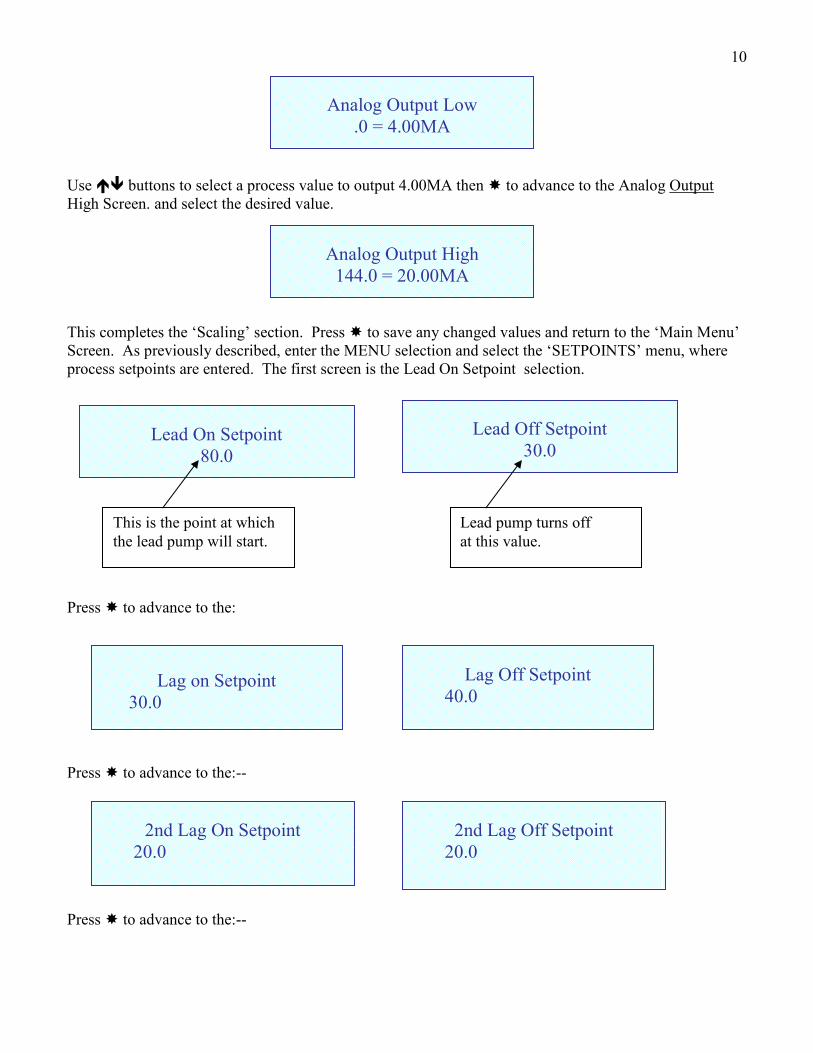
SIMULATOR SCREEN
The simulator screen allows the user to simulate a changing process to test all system setpoints and
functions.
From the main menu select the simulator screen, the current process value will be displayed. Press
the�� buttons to raise or lower the process value.
Note the screen will flash the word ‘simulator’ to remind the operator that the controller is in the
simulate mode. If no buttons are pressed, the controller will return to the main menu in 30 seconds.
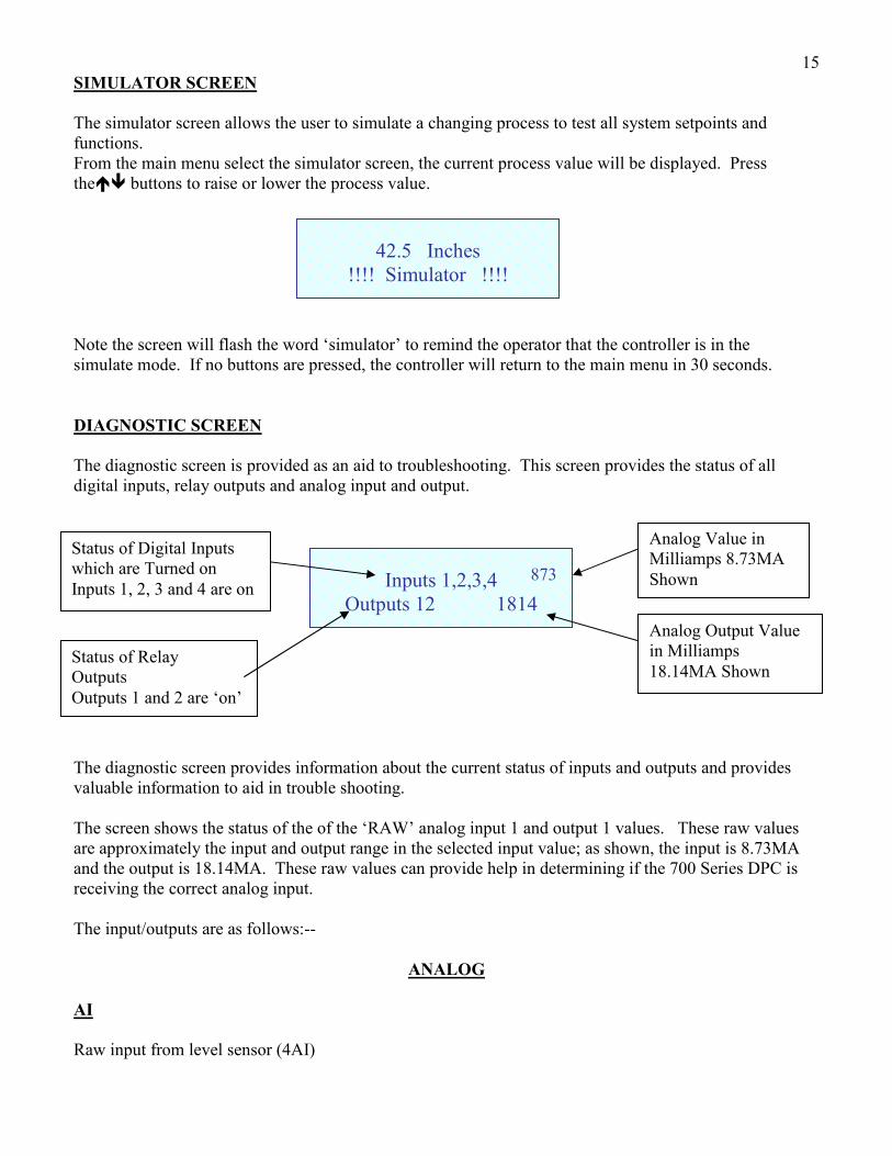
DIAGNOSTIC SCREEN
The diagnostic screen is provided as an aid to troubleshooting. This screen provides the status of all
digital inputs, relay outputs and analog input and output.
The diagnostic screen provides information about the current status of inputs and outputs and provides
valuable information to aid in trouble shooting.
The screen shows the status of the of the ‘RAW’ analog input 1 and output 1 values. These raw values
are approximately the input and output range in the selected input value; as shown, the input is 8.73MA
and the output is 18.14MA. These raw values can provide help in determining if the 700 Series DPC is
receiving the correct analog input.
The input/outputs are as follows:--
ANALOG
AI
Raw input from level sensor (4AI)
42.5 Inches
!!!! Simulator !!!!
Inputs 1,2,3,4
Outputs 12 1814
Status of Digital Inputs
which are Turned on
Inputs 1, 2, 3 and 4 are on
Status of Relay
Outputs
Outputs 1 and 2 are ‘on’
873
Analog Value in
Milliamps 8.73MA
Shown
Analog Output Value
in Milliamps
18.14MA Shown

16
AO
#1 (AOI)
DIGITAL
DIGITAL INPUT
Pump 1 Run Feedback / Critical (NC) 1DI
Pump 2 Run Feedback / Critical (NC) 2DI
Pump 3 Run Feedback / Critical (NC) 3DI
Pump 1 HOA in Auto 4DI
Pump 2 HOA in Auto 5DI
Pum 3 HOA in Auto 6DI
Seal Fail 7DI
External Reset 8DI
DIGITAL OUTPUT
1 Relay 1 Run to Pump 1 RLY1
2 Relay 2 Run to Pump 2 RLY2
3 Level Alarm RLY3
4 General Alarm RLY4
NOTES ON ALARMS
General Alarm output is energized if any alarm in the system becomes active.
PUMP ALARMS
(1) Pump Fail, after a pump has been ‘called’ to run a digital input (normally from the auxiliary contact on
the respective motor starter) is ‘feedback’ to the controller at 1DI, 2DI and 3DI. If the controller fails to
see this input within the alarm timer setting it assumes the motor starter has failed to energize and it
energizes the ‘Pump Failed to Run’ alarm, removes this pump from the sequence and brings on the next
available pump.
(2) Critical Alarm, the critical alarm inputs are in ‘series’ with the run feedback at DI1, 2 & 3 or normally
closed inputs usually from the pump motor thermostats or VFD faults. If the controller ‘sees’ either of
these inputs go open, then the “pump fail” is brought up on the screen and the respective pump is shut
down. The next pump is brought on.
(3) Seal Leak, All seal leak inputs are connected to a single digital input 7DI. When any of these are
closed the non-critical alarm is activated. The pumps are not shut down, but the “seal fail alarm” appears
on the screen.
(4) H.O.A. selectors, are monitored for their position at 4, 5 and 6 DI. If an HOA is not in the ‘Auto’
position that pump will not be permitted to run.
5) External Reset button can be connected to 8DI. When activated, it will clear any active alarm. Alarms
will be reset on the controller by pressing �� buttons simultaneously.
17
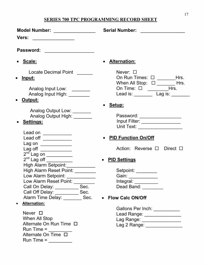
SERIES 700 TPC PROGRAMMING RECORD SHEET
Model Number: ________________ Serial Number: _________________
Vers: ________________
Password: ___________________
• Scale: Locate Decimal Point ______
• Input: Analog Input Low: _______ Analog Input High: ________
• Output:
Analog Output Low: _______ Analog Output High: _______
• Settings: Lead on ___________ Lead off ___________ Lag on ____________ Lag off ____________ 2nd Lag on __________ 2nd Lag off __________ High Alarm Setpoint:___________ High Alarm Reset Point: ________ Low Alarm Setpoint: ___________ Low Alarm Reset Point: ________ Call On Delay: _________ Sec. Call Off Delay: _________ Sec. Alarm Time Delay: _______ Sec.
• Alternation: Never: � On Run Times: � _______Hrs. When All Stop: � _______ Hrs. On Time: � ________Hrs. Lead is: _______ Lag is: _______
• Setup: Password: ________________ Input Filter: _______________ Unit Text: _________________
• PID Function On/Off Action: Reverse � Direct �
• PID Settings Setpoint: ________ Gain: ___________ Integral: _________ Dead Band: ________
• Flow Calc ON/Off Gallons Per Inch: __________ Lead Range: ______________ Lag Range: _______________ Lag 2 Range: ______________
• Alternation:
Never � When All Stop Alternate On Run Time � Run Time = _________ Alternate On Time � Run Time = _________

18
• DISPLAY REMAINS AT ZERO OR SHOWS NO CHANGE -- If the display remains at zero or shows no change but the process is changing, check for DC voltage on the loop. With 2 wire (4/20MA)
instruments check with a DC voltmeter at the level instrument, by disconnecting the level instrument
from its 2 wires and measuring across these 2 wires with a DC voltmeter for the presence of 24VDC.
Check the diagnostic screen for analog input value.
If DC voltage is present, reconnect the negative wire of the supply and insert a milliampmeter between
the positive wires. The loop should provide a signal between 4 and 20 MA. If no current is present
or & current exceeds 20MA consult the level instrument supplier.
If DC voltage is not present check the user supplied power supply or if using the 700 DPC supply
measure across terminals 24VDC and + and -. If no 24VDC is present consult factory. If 24VDC is
present check field wiring between the 700 DPC and the field device and recheck ‘SCALE’ functions to
ensure correct setup.
NOTE: This should be done by using the user provided circuit breaker or fuse,
not by removing the power wires at the terminal block. Serious injury or death
can occur if contact is made with the incoming AC power.
MAINTENANCE AND TROUBLE SHOOTING
The Series 700 TPC is a digital solid state device which requires no periodic maintenance.
Occasional physical checks of the unit should be carried out for physical and mechanical security of
mounting, terminal blocks, and electrical wiring.
TROUBLE SHOOTING
• UNIT ‘LOCKS UP’ -- Recycle power to the unit by removing AC power, waiting 10 seconds and reconnecting power.

19
WARRANTY All Sigma Controls, Inc. products are warranted to be free from defective
materials and workmanship for one (1) year from date of shipment. Sigma
reserves the right to repair or replace at its option any product found to be
defective. In no event shall Sigma Controls, Inc. be liable for any
consequential, incidental, or special damages and the limit of its liability shall
not exceed the purchase price of the supplied equipment.
*****IMPORTANT*****
SENSORS AND CABLE THAT HAVE BEEN USED IN WASTE WATER
OR HAZARDOUS LIQUIDS MUST BE THOROUGHLY CLEANED
BEFORE RETURNING. UNITS RETURNED UNCLEANED WILL BE
CONSIDERED UNREPAIRABLE AND RETURNED TO SENDER OR
DISCARDED. NOTE: DO NOT SUBMERGE UNITS FOR CLEANING
WITH CABLE CUT OR REMOVED. THIS WILL ALLOW CLEANING
FLUID TO ENTER HOUSING, DAMAGING ELECTRONICS AND
VOIDING THE WARRANTY.
RETURN FOR REPAIR POLICY (WARRANTY/NON-WARRANTY REPAIR)
Return status can be determined upon factory inspection of returned equipment. A completed Return Authorization form must accompany all items returned for repair. Repairs will be evaluated as quickly as possible. Cost for non-warranty repairs will be provided before repairs are initiated and repairs will be completed only after approval by customer. 217 S. Fifth Street, Perkasie, PA 18944 PH: 215-257-3412 FAX: 215-257-3416
Recommended