EE 323 -Feedback and stability Page 1 of 27
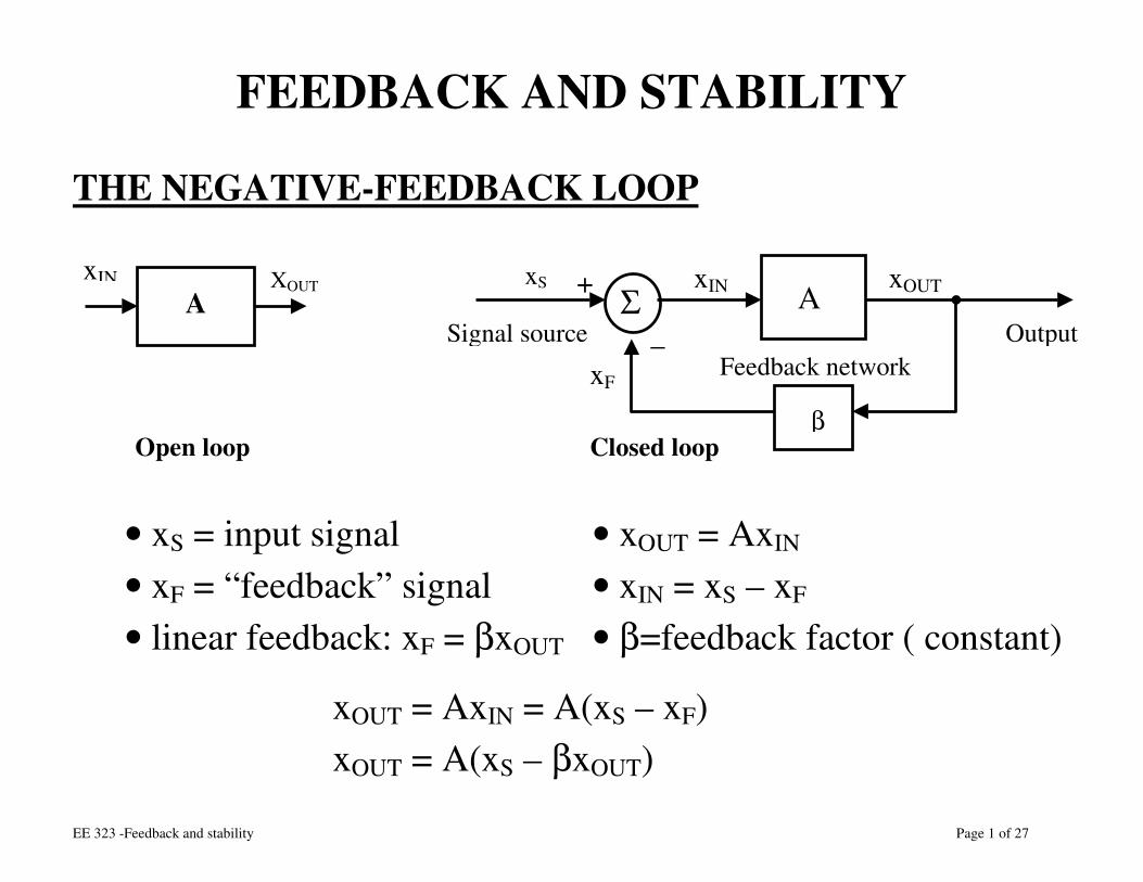
FEEDBACK AND STABILITY
THE NEGATIVE-FEEDBACK LOOP
• xS = input signal • xOUT = AxIN • xF = “feedback” signal • xIN = xS – xF • linear feedback: xF = βxOUT • β=feedback factor ( constant)
xOUT = AxIN = A(xS – xF) xOUT = A(xS – βxOUT)
xIN XOUT A Σ A
β
xS xIN xOUT
xF
+
_ Feedback network
Output Signal source
Open loop Closed loop
EE 323 -Feedback and stability Page 2 of 27
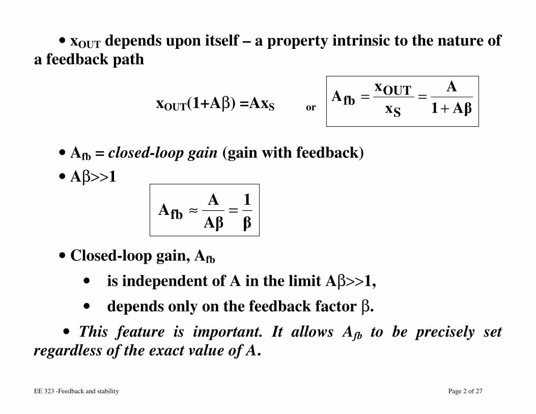
• xOUT depends upon itself – a property intrinsic to the nature of a feedback path
xOUT(1+Aβ) =AxS or A1A
xx
AS
OUTfb +
==
• Afb = closed-loop gain (gain with feedback) • Aβ>>1
1AAAfb =≈
• Closed-loop gain, Afb • is independent of A in the limit Aβ>>1, • depends only on the feedback factor β.
• This feature is important. It allows Afb to be precisely set regardless of the exact value of A.
EE 323 -Feedback and stability Page 3 of 27
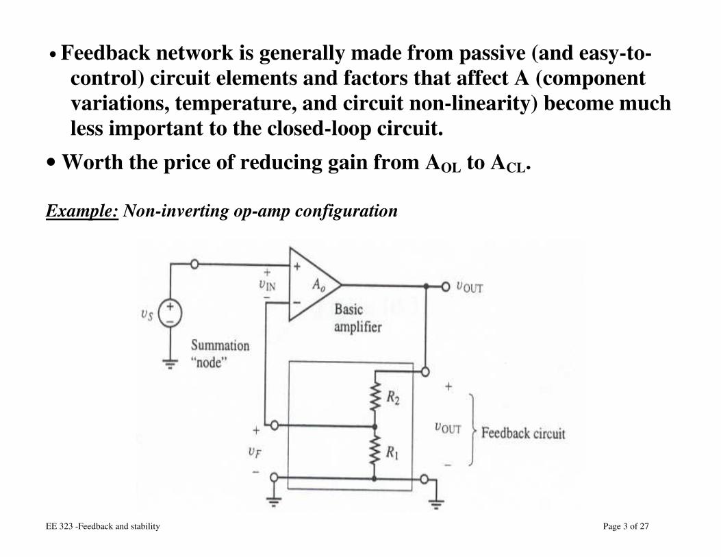
• Feedback network is generally made from passive (and easy-to-control) circuit elements and factors that affect A (component variations, temperature, and circuit non-linearity) become much less important to the closed-loop circuit.
• Worth the price of reducing gain from AOL to ACL.
Example: Non-inverting op-amp configuration
EE 323 -Feedback and stability Page 4 of 27
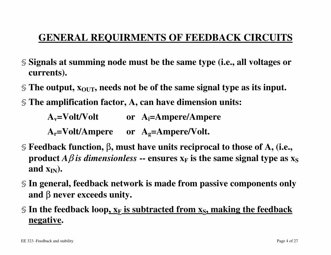
GENERAL REQUIRMENTS OF FEEDBACK CIRCUITS
§ Signals at summing node must be the same type (i.e., all voltages or currents).
§ The output, xOUT, needs not be of the same signal type as its input. § The amplification factor, A, can have dimension units:
Ø Av=Volt/Volt or Ai=Ampere/Ampere Ø Ar=Volt/Ampere or Ag=Ampere/Volt.
§ Feedback function, β, must have units reciprocal to those of A, (i.e., product Aβ is dimensionless -- ensures xF is the same signal type as xS and xIN).
§ In general, feedback network is made from passive components only and β never exceeds unity.
§ In the feedback loop, xF is subtracted from xS, making the feedback negative.
EE 323 -Feedback and stability Page 5 of 27
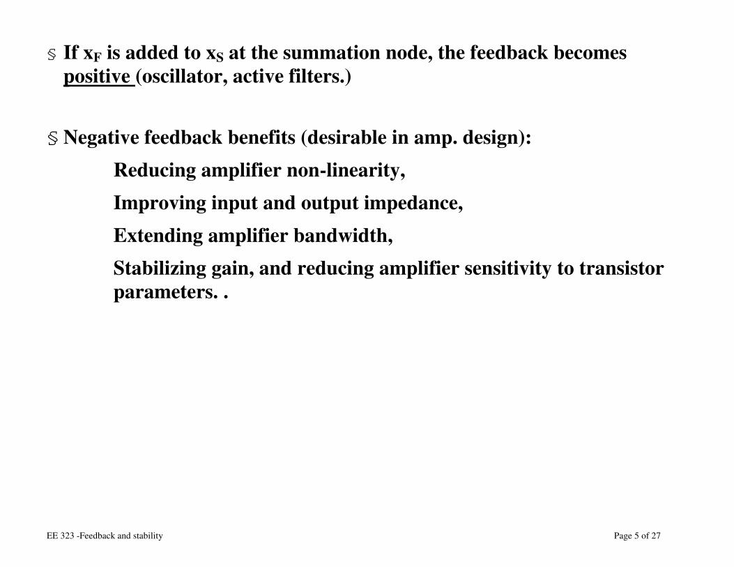
§ If xF is added to xS at the summation node, the feedback becomes positive (oscillator, active filters.)
§ Negative feedback benefits (desirable in amp. design): Ø Reducing amplifier non-linearity, Ø Improving input and output impedance, Ø Extending amplifier bandwidth, Ø Stabilizing gain, and reducing amplifier sensitivity to transistor
parameters. .
EE 323 -Feedback and stability Page 6 of 27
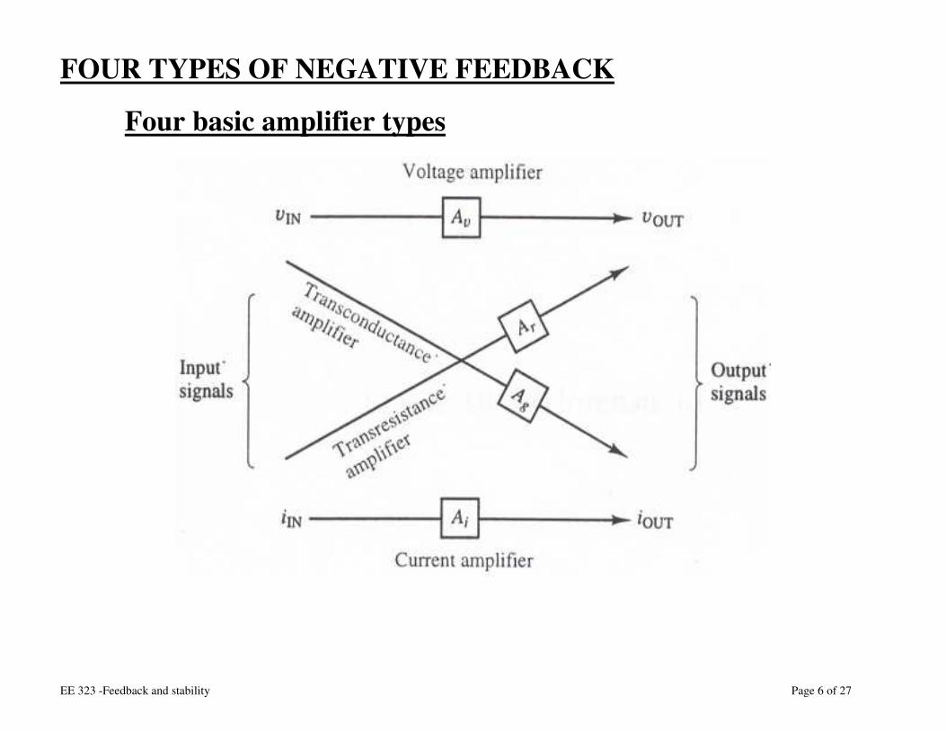
FOUR TYPES OF NEGATIVE FEEDBACK
Ø Four basic amplifier types
EE 323 -Feedback and stability Page 7 of 27
a. A voltage amplifier with gain Av
b. A current amplifier with gain Ai
c. A transconductance amplifier or voltage-to-current converter. The amplification factor, Ag, or
gm = iOUT/vIN, (A/V or conductance).
d. A transresistance amplifier or current-to-voltage converter. The amplification factor, Ar or
rm, = vOUT/iIN (V/A or resistance).
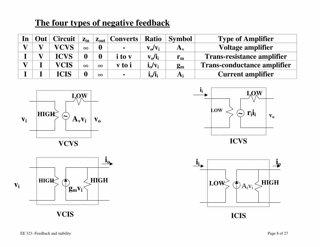
EE 323 -Feedback and stability Page 8 of 27
Ø The four types of negative feedback In Out Circuit zin zout Converts Ratio Symbol Type of Amplifier
V V VCVS ∞ 0 - vo/vi Av Voltage amplifier I V ICVS 0 0 i to v vo/ii rm Trans-resistance amplifier V I VCIS ∞ ∞ v to i io/vi gm Trans-conductance amplifier I I ICIS 0 ∞ - io/ii Ai Current amplifier
vi vo Avvi HIGH
LOW
VCVS
ii
vo riii LOW
LOW
ICVS
io
gmvi HIGH HIGH
VCIS
~ ~
io
Aivi LOW HIGH
ii
ICIS
vi
EE 323 -Feedback and stability Page 9 of 27
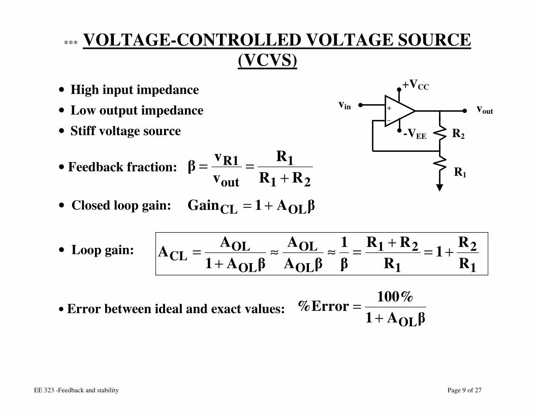
∗∗∗ VOLTAGE-CONTROLLED VOLTAGE SOURCE (VCVS)
• High input impedance • Low output impedance • Stiff voltage source
• Feedback fraction:
• Closed loop gain: • Loop gain:
• Error between ideal and exact values:
211
out1R
RRR
vv
+==
12
121
OL
OL
OL
OLCL R
R1R
RR1AA
A1AA +=+=≈≈
+=
vin vout + _
R1
+VCC
-VEE R2
A1%100Error%OL+
=
A1Gain OLCL +=
EE 323 -Feedback and stability Page 10 of 27
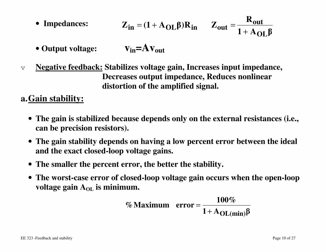
• Impedances:
• Output voltage: vin=Avout v Negative feedback: Stabilizes voltage gain, Increases input impedance,
Decreases output impedance, Reduces nonlinear distortion of the amplified signal.
a. Gain stability:
• The gain is stabilized because depends only on the external resistances (i.e., can be precision resistors).
• The gain stability depends on having a low percent error between the ideal and the exact closed-loop voltage gains.
• The smaller the percent error, the better the stability. • The worst-case error of closed-loop voltage gain occurs when the open-loop
voltage gain AOL is minimum.
A1%100errorMaximum%(min)OL+
=
A1RZR)A1(Z
OL
outoutinOLin +
=+=
EE 323 -Feedback and stability Page 11 of 27
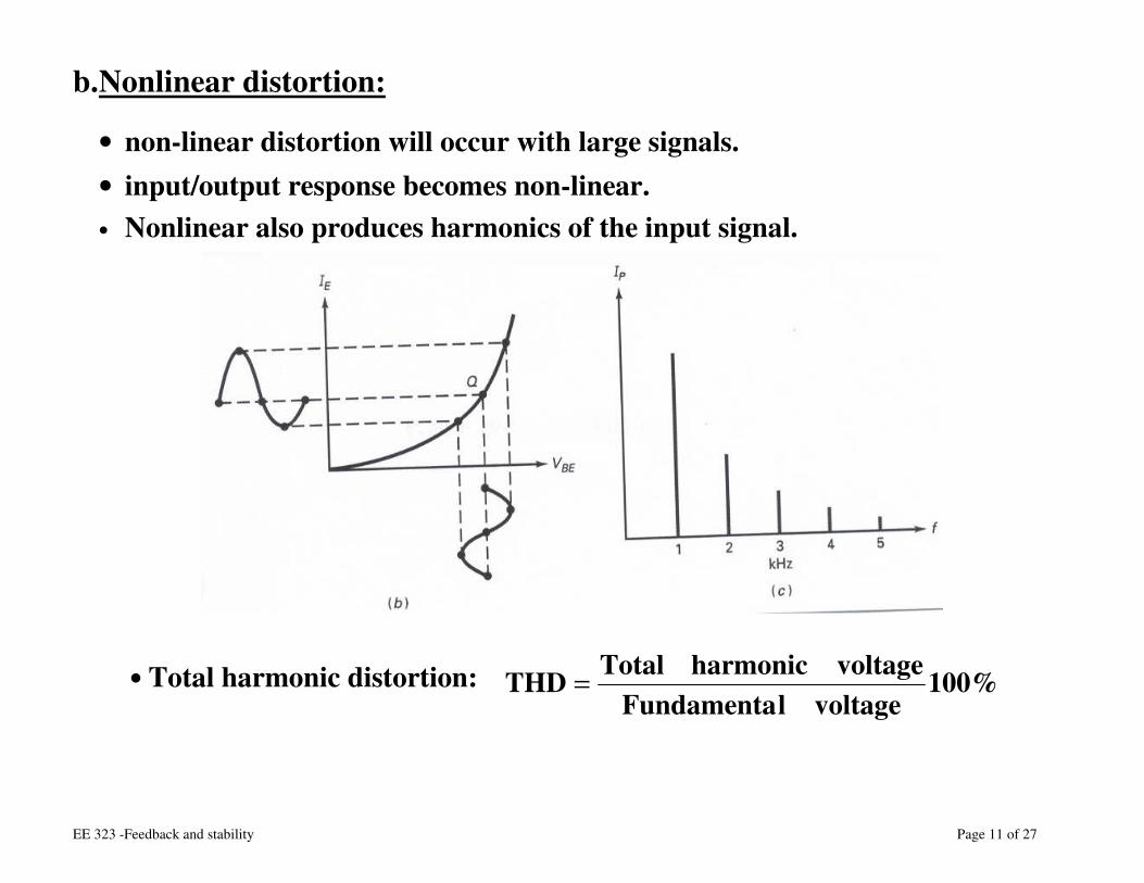
b. Nonlinear distortion:
• non-linear distortion will occur with large signals. • input/output response becomes non-linear. • Nonlinear also produces harmonics of the input signal.
• Total harmonic distortion:
%100voltagelFundamenta
voltageharmonicTotalTHD =
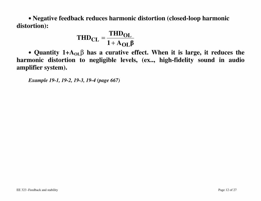
EE 323 -Feedback and stability Page 12 of 27
• Negative feedback reduces harmonic distortion (closed-loop harmonic distortion):
A1THDTHD
OL
OLCL +
=
• Quantity 1+AOLβ has a curative effect. When it is large, it reduces the harmonic distortion to negligible levels, (ex.., high-fidelity sound in audio amplifier system).
Example 19-1, 19-2, 19-3, 19-4 (page 667)
EE 323 -Feedback and stability Page 13 of 27
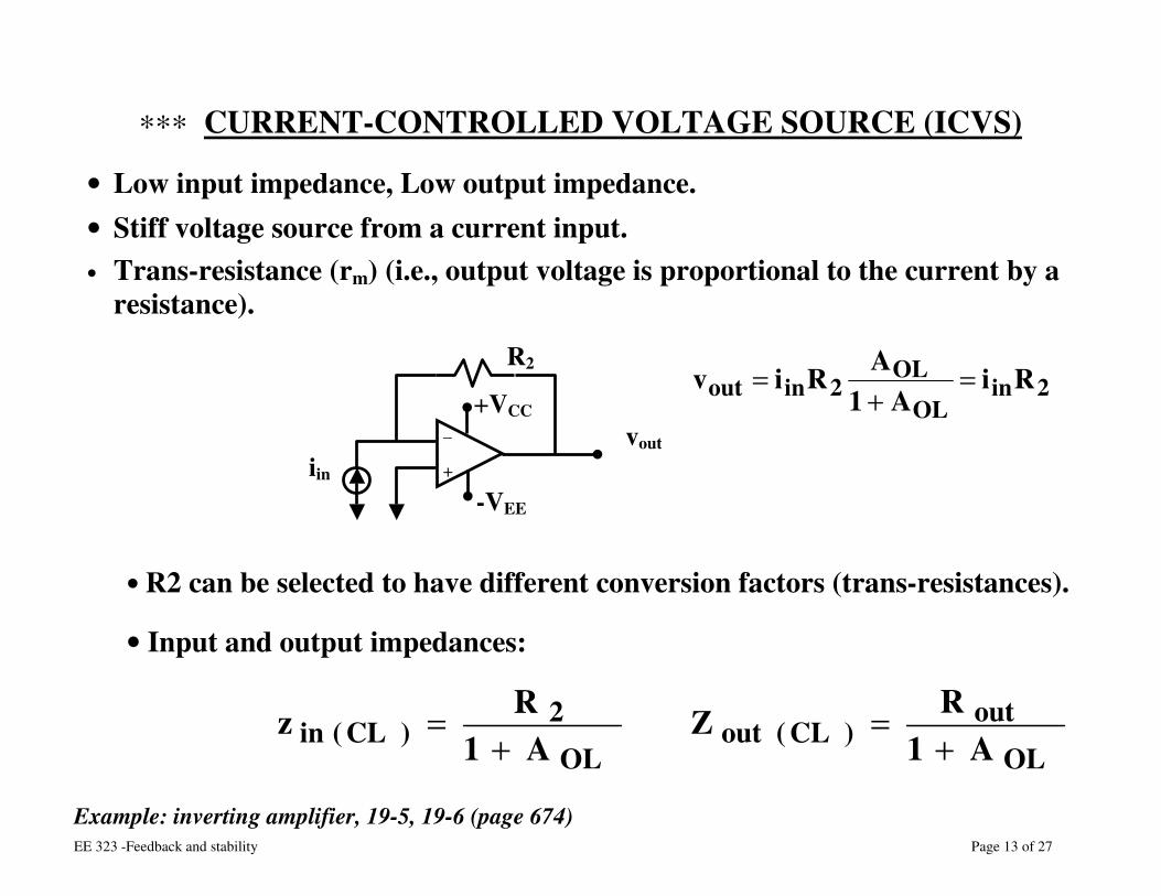
∗∗∗ CURRENT-CONTROLLED VOLTAGE SOURCE (ICVS)
• Low input impedance, Low output impedance. • Stiff voltage source from a current input. • Trans-resistance (rm) (i.e., output voltage is proportional to the current by a
resistance).
• R2 can be selected to have different conversion factors (trans-resistances).
• Input and output impedances:
Example: inverting amplifier, 19-5, 19-6 (page 674)
2inOL
OL2inout Ri
A1ARiv =+
=
OL
out)CL(out
OL
2)CL(in A1
RZA1
Rz+
=+
=
iin vout _
+
+VCC
-VEE
R2
EE 323 -Feedback and stability Page 14 of 27
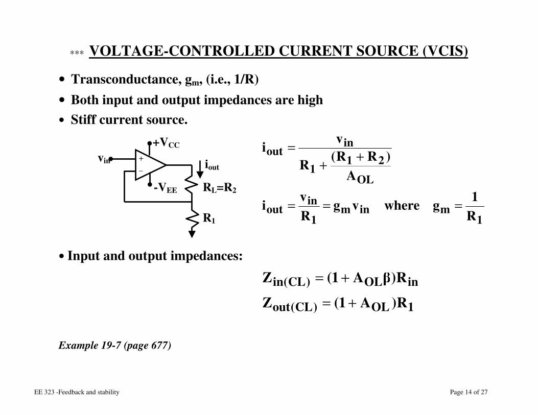
∗∗∗ VOLTAGE-CONTROLLED CURRENT SOURCE (VCIS)
• Transconductance, gm, (i.e., 1/R) • Both input and output impedances are high • Stiff current source.
• Input and output impedances:
Example 19-7 (page 677)
1minm
1
inout
OL
211
inout
R1gwherevg
Rvi
A)RR(R
vi
===
++=
1OL)CL(out
inOL)CL(in
R)A1(Z
R)A1(Z
+=
+=
vin iout + _
R1
+VCC
-VEE RL=R2
EE 323 -Feedback and stability Page 15 of 27
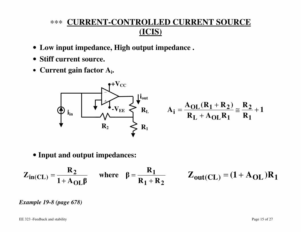
∗∗∗ CURRENT-CONTROLLED CURRENT SOURCE (ICIS)
• Low input impedance, High output impedance . • Stiff current source. • Current gain factor Ai.
• Input and output impedances:
Example 19-8 (page 678)
iin
iout _ +
R1
+VCC
-VEE RL
R2
1RR
RAR)RR(AA
1
2
1OLL
21OLi +≅
++=
21
1
OL
2)CL(in RR
RwhereA1RZ
+=
+= 1OL)CL(out R)A1(Z +=
EE 323 -Feedback and stability Page 16 of 27
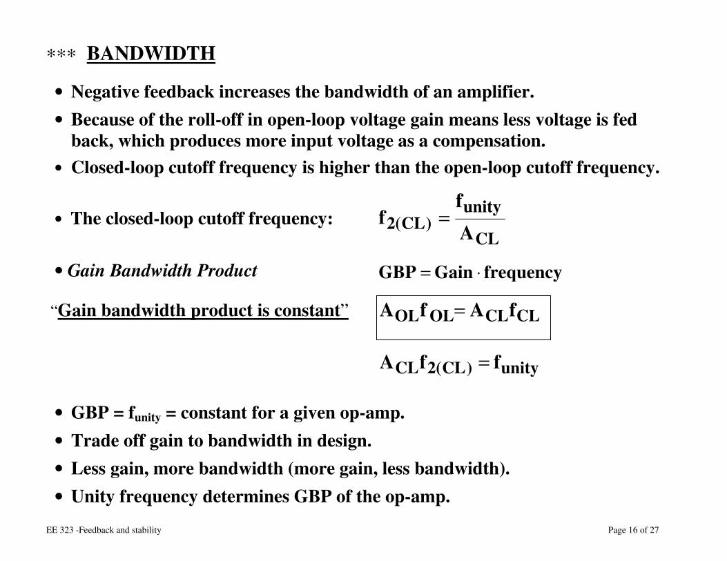
∗∗∗ BANDWIDTH
• Negative feedback increases the bandwidth of an amplifier. • Because of the roll-off in open-loop voltage gain means less voltage is fed
back, which produces more input voltage as a compensation. • Closed-loop cutoff frequency is higher than the open-loop cutoff frequency.
• The closed-loop cutoff frequency:
• Gain Bandwidth Product
“Gain bandwidth product is constant”
unity)CL(2CL ffA =
• GBP = funity = constant for a given op-amp. • Trade off gain to bandwidth in design. • Less gain, more bandwidth (more gain, less bandwidth). • Unity frequency determines GBP of the op-amp.
CL
unity)CL(2 A
ff =
frequencyGainGBP ⋅=
CLCLOLOL fAfA =
EE 323 -Feedback and stability Page 17 of 27
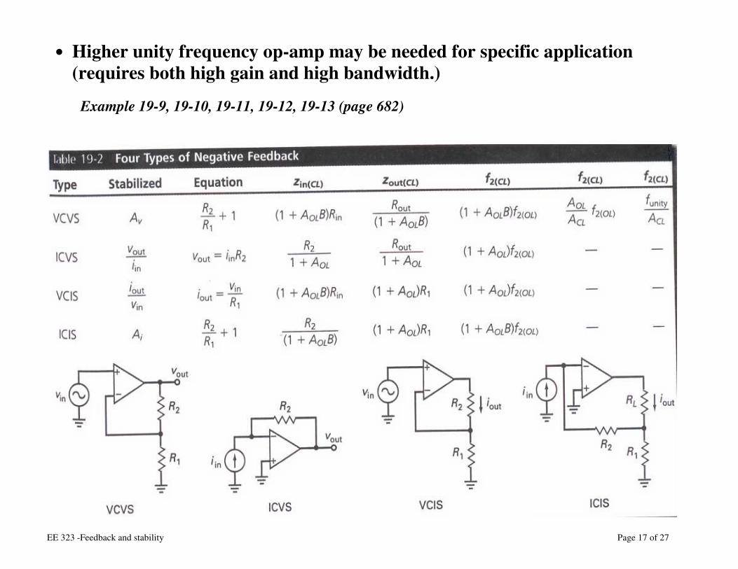
• Higher unity frequency op-amp may be needed for specific application (requires both high gain and high bandwidth.)
Example 19-9, 19-10, 19-11, 19-12, 19-13 (page 682)
EE 323 -Feedback and stability Page 18 of 27
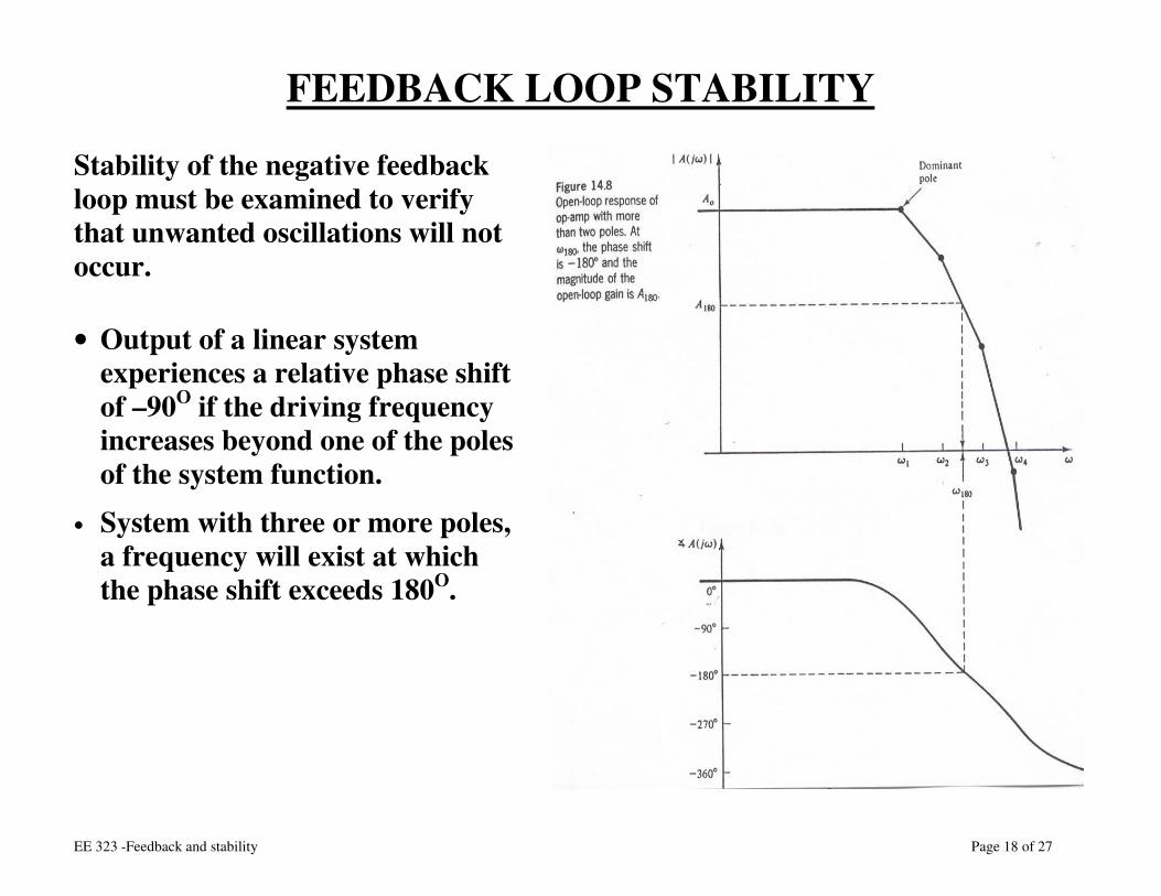
FEEDBACK LOOP STABILITY
Stability of the negative feedback loop must be examined to verify that unwanted oscillations will not occur.
• Output of a linear system experiences a relative phase shift of –90O if the driving frequency increases beyond one of the poles of the system function.
• System with three or more poles, a frequency will exist at which the phase shift exceeds 180O.
EE 323 -Feedback and stability Page 19 of 27
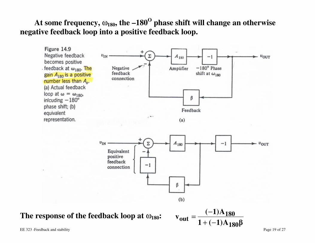
At some frequency, ω180, the –180O phase shift will change an otherwise negative feedback loop into a positive feedback loop.
The response of the feedback loop at ω180: A)1(1
A)1(v180
180out −+
−=
EE 323 -Feedback and stability Page 20 of 27
• If A180β=1, the denominator becomes 0 and the output becomes infinite (even vin = 0).
• Such a condition is equivalent to an oscillation at the frequency ω 180. • Less stringent inequality A180β≥1 also leads to oscillation at ω180.
• Note: in practice, the saturation limits of the op-amp limit the magnitude of oscillation.
I. FEEDBACK LOOP COMPENSATION
§ Use frequency compensation to prevent unwanted oscillations (at ω180). § Alter the open loop response so that the stability condition is met: A180β < 1 § Internal design (stability condition is met up to some maximum value of β,
i.e., β=1). § The LM741 is stable under all negative feedback conditions. The value of A180
of LM741 is less than unity.
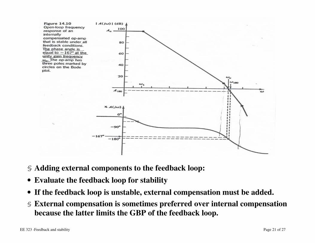
EE 323 -Feedback and stability Page 21 of 27
§ Adding external components to the feedback loop: • Evaluate the feedback loop for stability • If the feedback loop is unstable, external compensation must be added. § External compensation is sometimes preferred over internal compensation
because the latter limits the GBP of the feedback loop.
EE 323 -Feedback and stability Page 22 of 27
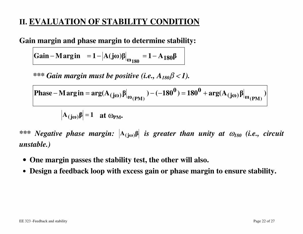
II. EVALUATION OF STABILITY CONDITION
Gain margin and phase margin to determine stability:
A1)j(A1inargMGain 180180−=−=−
*** Gain margin must be positive (i.e., A180β < 1).
)Aarg(180)180()Aarg(inargMPhase)PM()PM( )j(
00)j( +=−−=−
1A )j( = at ωPM.
*** Negative phase margin: A )j( is greater than unity at ω180 (i.e., circuit unstable.)
• One margin passes the stability test, the other will also. • Design a feedback loop with excess gain or phase margin to ensure stability.
EE 323 -Feedback and stability Page 23 of 27
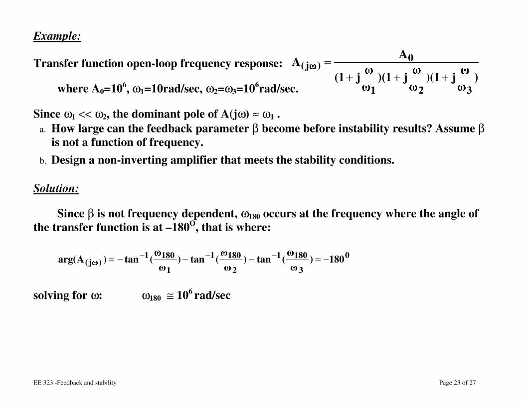
Example: Transfer function open-loop frequency response:
where A0=106, ω1=10rad/sec, ω2=ω3=106rad/sec.
Since ω1 << ω2, the dominant pole of A(jω) ≈ ω1 . a. How large can the feedback parameter β become before instability results? Assume β
is not a function of frequency. b. Design a non-inverting amplifier that meets the stability conditions.
Solution:
Since β is not frequency dependent, ω180 occurs at the frequency where the angle of the transfer function is at –180O, that is where:
0
3
1801
2
1801
1
1801)j( 180)(tan)(tan)(tan)Aarg( −=−−−= −−−
solving for ω: ω180 ≅ 106 rad/sec
)j1)(j1)(j1(
AA
321
0)j(
+++=
EE 323 -Feedback and stability Page 24 of 27
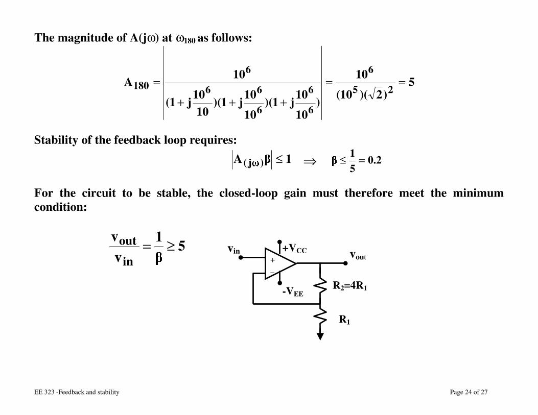
The magnitude of A(jω) at ω180 as follows:
5)2)(10(
10
)10
10j1)(10
10j1)(10
10j1(
10A25
6
6
6
6
66
6180 ==
+++
=
Stability of the feedback loop requires:
1A )j( ≤ ⇒ 2.051 =≤
For the circuit to be stable, the closed-loop gain must therefore meet the minimum condition:
51vv
in
out ≥=
vin vout + _
R1
+VCC
-VEE R2=4R1
EE 323 -Feedback and stability Page 25 of 27
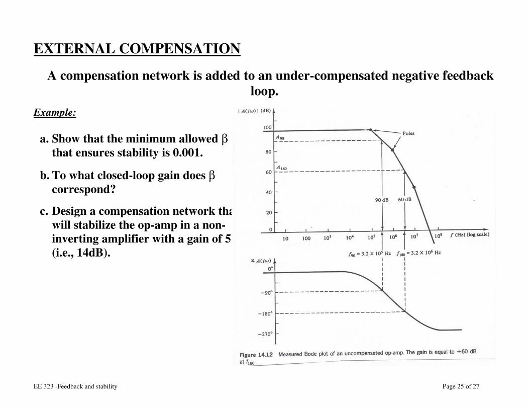
EXTERNAL COMPENSATION
A compensation network is added to an under-compensated negative feedback loop.
Example:
a. Show that the minimum allowed β that ensures stability is 0.001.
b. To what closed-loop gain does β correspond?
c. Design a compensation network that will stabilize the op-amp in a non-inverting amplifier with a gain of 5 (i.e., 14dB).
EE 323 -Feedback and stability Page 26 of 27
Solution:
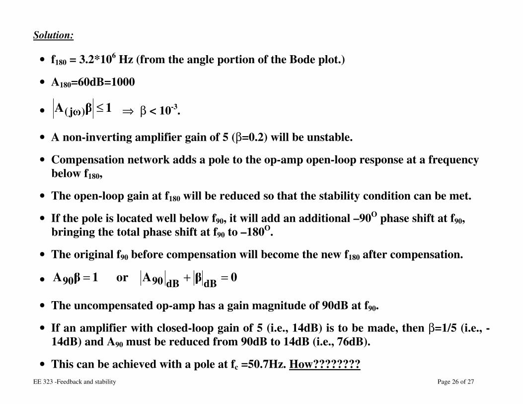
• f180 = 3.2*106 Hz (from the angle portion of the Bode plot.)
• A180=60dB=1000
• 1A )j( ≤ ⇒ β < 10-3.
• A non-inverting amplifier gain of 5 (β=0.2) will be unstable.
• Compensation network adds a pole to the op-amp open-loop response at a frequency below f180,
• The open-loop gain at f180 will be reduced so that the stability condition can be met.
• If the pole is located well below f90, it will add an additional –90O phase shift at f90, bringing the total phase shift at f90 to –180O.
• The original f90 before compensation will become the new f180 after compensation.
• 0Aor1A dBdB9090 =+=
• The uncompensated op-amp has a gain magnitude of 90dB at f90.
• If an amplifier with closed-loop gain of 5 (i.e., 14dB) is to be made, then β=1/5 (i.e., - 14dB) and A90 must be reduced from 90dB to 14dB (i.e., 76dB).
• This can be achieved with a pole at fc =50.7Hz. How????????
EE 323 -Feedback and stability Page 27 of 27
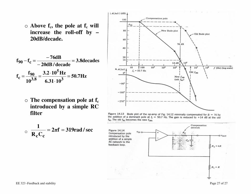
o Above fc, the pole at fc will
increase the roll-off by –20dB/decade.
Hz7.501031.6
Hz102.310ff
decades8.3decade/dB20dB76ff
3
5
8.390
c
c90
=⋅
⋅==
=−
−=−
o The compensation pole at fc introduced by a simple RC filter
o sec/rad319f2CR1
cc==
Recommended
![Endocrineelearning.kocw.net/contents4/document/lec/2013/Uiduk/...(estrogen and androgen) 9—29] Negative feedback Hypothalamus Gonadotropin— releasing hormone (GnRH) Anterior pituitary](https://img.pdfslide.tips/doc/110x75/5c932f4e09d3f21a398bbc96/estrogen-and-androgen-929-negative-feedback-hypothalamus-gonadotropin-releasing.jpg)