A REPORT TO
THE BOARD OF COMMISSIONERS OF PUBLIC UTILITIES
Electrical
Mechanical
'' ..,
Civil/
Protection & Control
-
Transmission & Distribution
Telecontrol
System Planning
UPGRADE TRANSMISSION LINE CORRIDORBay d'Espoir to Western Avalon
September 2011
newfoundland labrador
hydroa nalcor energy company
Upgrade Transmission Line Corridor – Bay d’Espoir to Western Avalon
Newfoundland and Labrador Hydro i
Table of Contents
1 INTRODUCTION................................................................................................................ 1
2 PROJECT DESCRIPTION..................................................................................................... 3
3 EXISTING SYSTEM............................................................................................................. 7 3.1 Age of Equipment or System ............................................................................... 9 3.2 Major Work and/or Upgrades ............................................................................. 9 3.3 Anticipated Useful life........................................................................................ 10 3.4 Maintenance History ......................................................................................... 11 3.5 Outage Statistics ................................................................................................ 11 3.6 Industry Experience ........................................................................................... 12 3.7 Maintenance or Support Arrangements............................................................ 13 3.8 Vendor Recommendations ................................................................................ 13 3.9 Availability of Replacement Parts ...................................................................... 13 3.11 Retirements........................................................................................................ 14 3.12 Safety Performance ........................................................................................... 14 3.13 Environmental Performance.............................................................................. 14 3.14 Operating Regime .............................................................................................. 14
4 JUSTIFICATION ............................................................................................................... 15 4.1 Net Present Value .............................................................................................. 35 4.2 Levelized Cost of Energy .................................................................................... 35 4.3 Cost Benefit Analysis.......................................................................................... 35 4.4 Legislative or Regulatory Requirements............................................................ 36 4.5 Historical Information........................................................................................ 36 4.6 Forecast Customer Growth................................................................................ 36 4.7 Energy Efficiency Benefits.................................................................................. 37 4.8 Losses During Construction ............................................................................... 37 4.9 Status Quo.......................................................................................................... 38 4.10 Alternatives........................................................................................................ 38
5 CONCLUSION.................................................................................................................. 40 5.2 Project Schedule ................................................................................................ 41
Upgrade Transmission Line Corridor – Bay d’Espoir to Western Avalon
Newfoundland and Labrador Hydro Page 1
1 INTRODUCTION
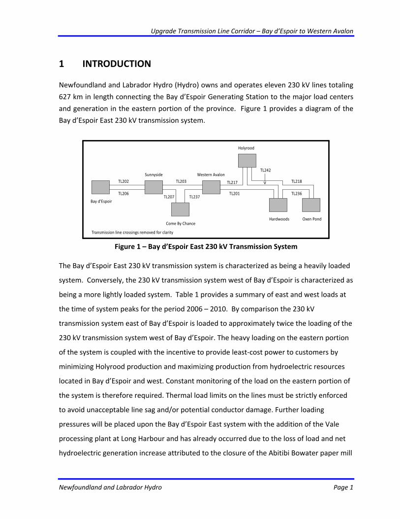
Newfoundland and Labrador Hydro (Hydro) owns and operates eleven 230 kV lines totaling
627 km in length connecting the Bay d’Espoir Generating Station to the major load centers
and generation in the eastern portion of the province. Figure 1 provides a diagram of the
Bay d’Espoir East 230 kV transmission system.
Bay d'Espoir
TL202
TL206
Sunnyside
Come By Chance
TL203
TL207 TL237
Holyrood
Western Avalon
TL217
TL201
Hardwoods Oxen Pond
TL218
TL236
TL242
Transmission line crossings removed for clarity
Figure 1 – Bay d’Espoir East 230 kV Transmission System
The Bay d’Espoir East 230 kV transmission system is characterized as being a heavily loaded
system. Conversely, the 230 kV transmission system west of Bay d’Espoir is characterized as
being a more lightly loaded system. Table 1 provides a summary of east and west loads at
the time of system peaks for the period 2006 – 2010. By comparison the 230 kV
transmission system east of Bay d’Espoir is loaded to approximately twice the loading of the
230 kV transmission system west of Bay d’Espoir. The heavy loading on the eastern portion
of the system is coupled with the incentive to provide least‐cost power to customers by
minimizing Holyrood production and maximizing production from hydroelectric resources
located in Bay d’Espoir and west. Constant monitoring of the load on the eastern portion of
the system is therefore required. Thermal load limits on the lines must be strictly enforced
to avoid unacceptable line sag and/or potential conductor damage. Further loading
pressures will be placed upon the Bay d’Espoir East system with the addition of the Vale
processing plant at Long Harbour and has already occurred due to the loss of load and net
hydroelectric generation increase attributed to the closure of the Abitibi Bowater paper mill
Upgrade Transmission Line Corridor – Bay d’Espoir to Western Avalon
Newfoundland and Labrador Hydro Page 2
in Grand Falls – Windsor.
Table 1 ‐ Bay d’Espoir East and West 230 kV Transmission System Peak Loads 2006 to 2010 Year Bay d’Espoir – East1 Bay d’Espoir – West2 2006 836 431 2007 848 450 2008 827 436 2009 858 428 2010 833 378
Notes 1‐ Bay d’Espoir – East load equal to TL202 and TL206 flow plus Paradise River, Holyrood
and Hardwoods generation at time of peak. 2‐ Bay d’Espoir – West load equal to TL204 and TL231 flow plus Cat Arm, Hinds Lake,
Stephenville, Hawke’s Bay, St. Anthony Diesel Plant generation and Non‐Utility Generation purchases at time of peak.
3‐ Connaigre Peninsula loads not included 4‐ Values based on the Hydro Energy Management System (EMS) hourly data and not
weather adjusted
Lower Churchill Impacts
Given that the Lower Churchill Project has yet to receive final project sanction, analysis of
the Bay d’Espoir East 230 kV transmission system must consider both the continued Isolated
Island Scenario and the Labrador Infeed Scenario. In effect, the proposed project must be
appropriate to either an Isolated Island or Labrador‐Interconnected future.
To accomplish this, the Bay d’Espoir East 230 kV transmission system was split into two
sections – Bay d’Espoir to Western Avalon and Western Avalon to St. John’s. This project
considers only the upgrade requirements for the Bay d’Espoir to Western Avalon section of
the Bay d’Espoir East 230 kV transmission system. The Western Avalon to St. John’s section
can only be considered once the decision on the Lower Churchill Project and subsequent
need for the Soldiers Pond Terminal Station is made. With the final decision on the Lower
Churchill Project scheduled for late 2011 or early 2012, Hydro intends to submit any
necessary upgrade projects for the Western Avalon to St. John’s section of the Bay d’Espoir
East 230 kV transmission system associated with the proposed Lower Churchill Project to
The Board as part of its 2013 capital budget application.
Upgrade Transmission Line Corridor – Bay d’Espoir to Western Avalon
Newfoundland and Labrador Hydro Page 3
2 PROJECT DESCRIPTION The Upgrade Transmission Line Corridor – Bay d’Espoir to Western Avalon project will
consist of a new 230 kV transmission line, 188 km in length connecting Bay d’Espoir and
Western Avalon Terminal Stations. This includes construction of a 230 kV steel tower
transmission line complete with overhead ground wire over its entire length. A minimum
conductor size of 795 kcmil, 26/7 ACSR “DRAKE” with a 75 ˚C conductor temperature rating
or 804 kcmil 54/19 AACSR/TW with an 80 ˚C conductor temperature is required to provide
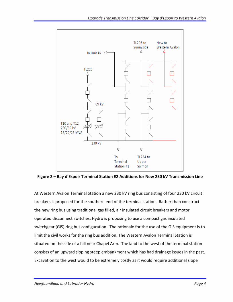
the necessary thermal rating for the new circuit. At Bay d’Espoir Terminal Station, three
230 kV circuit breakers, six 230 kV motor operated disconnect switches and associated
control panels will be added to complete the breaker‐and‐one‐half arrangement on the first
two legs of the station layout and accommodate the new 230 kV transmission line
termination on a third leg. Figure 2 provides a single line diagram with the proposed
additions in red.
Upgrade Transmission Line Corridor – Bay d’Espoir to Western Avalon
Newfoundland and Labrador Hydro Page 4
Figure 2 – Bay d’Espoir Terminal Station #2 Additions for New 230 kV Transmission Line
At Western Avalon Terminal Station a new 230 kV ring bus consisting of four 230 kV circuit
breakers is proposed for the southern end of the terminal station. Rather than construct
the new ring bus using traditional gas filled, air insulated circuit breakers and motor
operated disconnect switches, Hydro is proposing to use a compact gas insulated
switchgear (GIS) ring bus configuration. The rationale for the use of the GIS equipment is to
limit the civil works for the ring bus addition. The Western Avalon Terminal Station is
situated on the side of a hill near Chapel Arm. The land to the west of the terminal station
consists of an upward sloping steep embankment which has had drainage issues in the past.
Excavation to the west would to be extremely costly as it would require additional slope
Upgrade Transmission Line Corridor – Bay d’Espoir to Western Avalon
Newfoundland and Labrador Hydro Page 5
stability and drainage work along with relocation of the existing access road. The land to
the east consists of a downward sloping steep embankment to Route 201. Expansion in this
direction would require extensive amounts of fill. If acquisition of building lots for private
homes in the area of the Western Avalon Terminal Station were to be pursued, a minimal
extension to the south side of the station can be accommodated to permit installation of
the compact GIS and access road realignment. As part of the GIS ring bus addition, TL208
will be re‐terminated in the new ring along with the new 230 kV transmission line to Bay
d’Espoir. This will improve the reliability of the TL208 supply as it will no longer be tripped
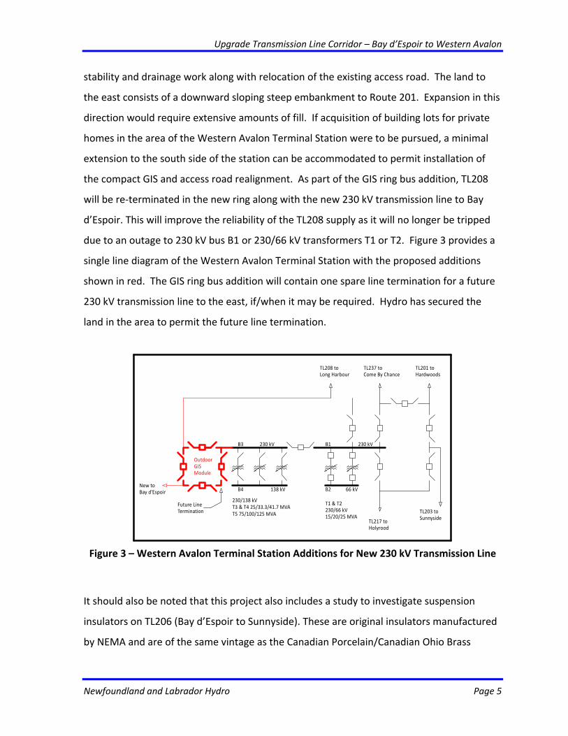
due to an outage to 230 kV bus B1 or 230/66 kV transformers T1 or T2. Figure 3 provides a
single line diagram of the Western Avalon Terminal Station with the proposed additions
shown in red. The GIS ring bus addition will contain one spare line termination for a future
230 kV transmission line to the east, if/when it may be required. Hydro has secured the
land in the area to permit the future line termination.
TL201 toHardwoods
TL217 toHolyrood
TL203 toSunnyside
TL237 toCome By Chance
TL208 toLong Harbour
66 kV
T1 & T2230/66 kV15/20/25 MVA
B1 230 kV
B2
B3 230 kV
B4 138 kV
230/138 kVT3 & T4 25/33.3/41.7 MVAT5 75/100/125 MVA
OutdoorGISModule
New toBay d'Espoir
Future LineTermination
Figure 3 – Western Avalon Terminal Station Additions for New 230 kV Transmission Line
It should also be noted that this project also includes a study to investigate suspension
insulators on TL206 (Bay d’Espoir to Sunnyside). These are original insulators manufactured
by NEMA and are of the same vintage as the Canadian Porcelain/Canadian Ohio Brass
Upgrade Transmission Line Corridor – Bay d’Espoir to Western Avalon
Newfoundland and Labrador Hydro Page 6
insulators that have experienced significant cement growth and mechanical failure over
time. However, there is little industry information on the long term mechanical and
electrical performance of the NEMA insulators. It is suspected that the NEMA insulators on
TL206 do not meet Hydro’s existing suspension insulator specification. To confirm the
residual mechanical strength of the NEMA insulators following 43 years in service, Hydro is
proposing to remove sample strings from service and complete laboratory testing. Cost of
this component is estimated at $50,000. Following testing Hydro will be in a better position
to report the condition of the TL206 insulators to the Board with a recommendation on a
replacement program for the NEMA insulators.
As discussed in the Justification Section below, analysis indicates that this new 230 kV
transmission line is required to increase firm system capacity in both the continued Isolated
Island Scenario and the Labrador Interconnected Scenario.
Upgrade Transmission Line Corridor – Bay d’Espoir to Western Avalon
Newfoundland and Labrador Hydro Page 7
3 EXISTING SYSTEM
The existing Bay d’Espoir to Western Avalon transmission corridor consists of five 230 kV
transmission lines including:
• TL202 – Bay d’Espoir to Western Avalon;
• TL203 – Sunnyside to Western Avalon;
• TL206 ‐ Bay d’Espoir to Western Avalon;
• TL207 – Sunnyside to Come By Chance; and
• TL237 – Come By Chance to Western Avalon.
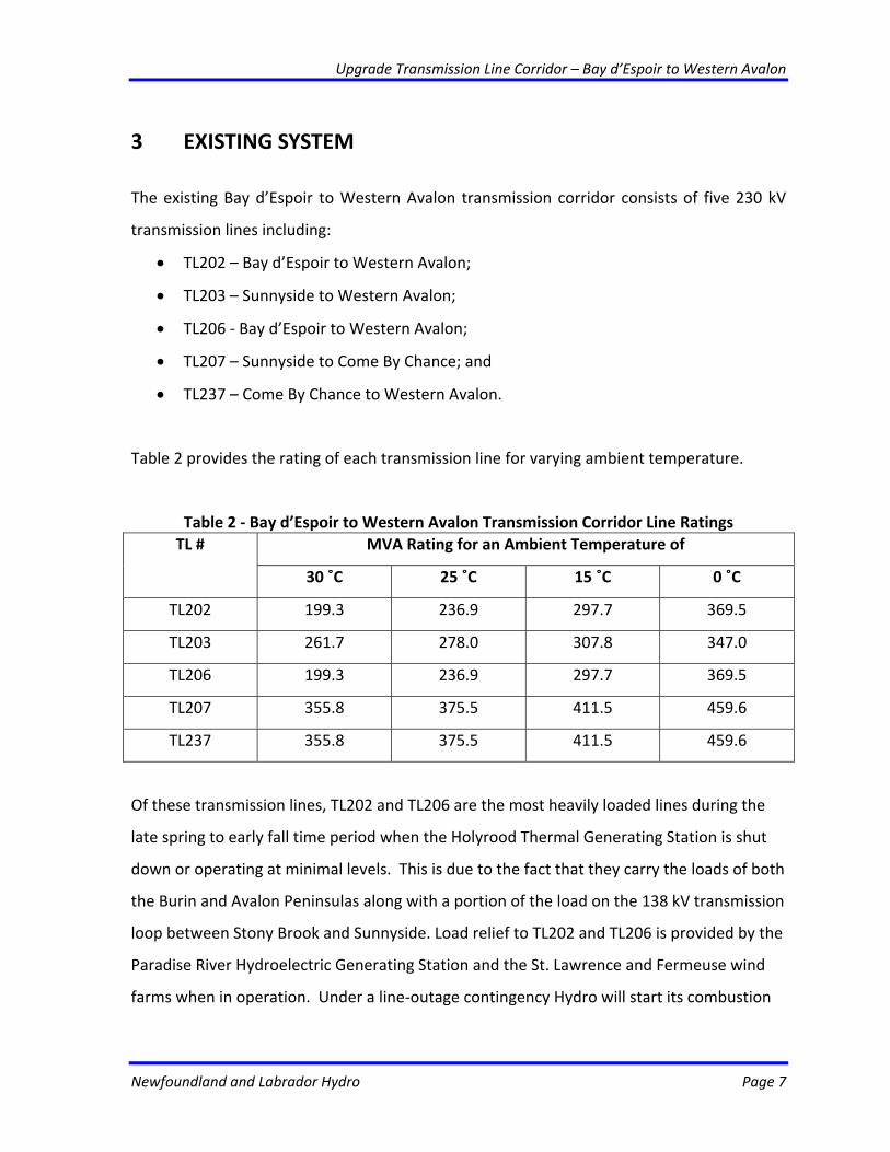
Table 2 provides the rating of each transmission line for varying ambient temperature.
Table 2 ‐ Bay d’Espoir to Western Avalon Transmission Corridor Line Ratings MVA Rating for an Ambient Temperature of TL #
30 ˚C 25 ˚C 15 ˚C 0 ˚C
TL202 199.3 236.9 297.7 369.5
TL203 261.7 278.0 307.8 347.0
TL206 199.3 236.9 297.7 369.5
TL207 355.8 375.5 411.5 459.6
TL237 355.8 375.5 411.5 459.6
Of these transmission lines, TL202 and TL206 are the most heavily loaded lines during the
late spring to early fall time period when the Holyrood Thermal Generating Station is shut
down or operating at minimal levels. This is due to the fact that they carry the loads of both
the Burin and Avalon Peninsulas along with a portion of the load on the 138 kV transmission
loop between Stony Brook and Sunnyside. Load relief to TL202 and TL206 is provided by the
Paradise River Hydroelectric Generating Station and the St. Lawrence and Fermeuse wind
farms when in operation. Under a line‐outage contingency Hydro will start its combustion
Upgrade Transmission Line Corridor – Bay d’Espoir to Western Avalon
Newfoundland and Labrador Hydro Page 8
turbines at Holyrood (10 MW) and Hardwoods (46 MW) to reduce the loading on the
transmission corridor. Given a thermal rating of 297.7 MVA on a 15 ˚C day (i.e. spring/fall)
Hydro must limit the loading on TL202 and TL206 to approximately 353 MW (297.7 + 10 +
46 = 353.7) to ensure that TL202 or TL206 does not become overloaded should TL206 or
TL202 trip. Consequently for Bay d’Espoir East loads in excess of 353 MW on a 15 ˚C day,
Hydro must operate generation at its Holyrood Thermal Generating Station.
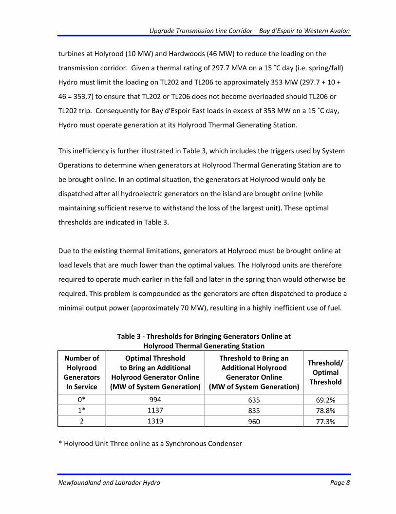
This inefficiency is further illustrated in Table 3, which includes the triggers used by System
Operations to determine when generators at Holyrood Thermal Generating Station are to
be brought online. In an optimal situation, the generators at Holyrood would only be
dispatched after all hydroelectric generators on the island are brought online (while
maintaining sufficient reserve to withstand the loss of the largest unit). These optimal
thresholds are indicated in Table 3.
Due to the existing thermal limitations, generators at Holyrood must be brought online at
load levels that are much lower than the optimal values. The Holyrood units are therefore
required to operate much earlier in the fall and later in the spring than would otherwise be
required. This problem is compounded as the generators are often dispatched to produce a
minimal output power (approximately 70 MW), resulting in a highly inefficient use of fuel.
Table 3 ‐ Thresholds for Bringing Generators Online at Holyrood Thermal Generating Station
Number of Holyrood Generators In Service
Optimal Threshold to Bring an Additional
Holyrood Generator Online (MW of System Generation)
Threshold to Bring an Additional Holyrood Generator Online
(MW of System Generation)
Threshold/Optimal Threshold
0* 994 635 69.2% 1* 1137 835 78.8% 2 1319 960 77.3%
* Holyrood Unit Three online as a Synchronous Condenser
Upgrade Transmission Line Corridor – Bay d’Espoir to Western Avalon
Newfoundland and Labrador Hydro Page 9
While these factors demonstrate significant restrictions in the operational flexibility of the
existing transmission system east of Bay d’Espoir, there is a much greater concern relating
to transfer capacity. In the event of the loss of a unit at Holyrood, the existing transmission
system would be unable to supply system loads above 1280 MW. While this analysis is
described in detail in Section 4, it may be noted that the peak load for 2012 is forecasted to
exceed 1350 MW. The loss of a unit at Holyrood would therefore result in a significant
exposure for unsupplied load.
3.1 Age of Equipment or System
The 230 kV transmission lines in the Bay d’Espoir to Western Avalon corridor were built
between 1965 and 1968. The original in service dates of the transmission lines are as
follows:
• TL202 – Bay d’Espoir to Sunnyside – 1966
• TL203 – Sunnyside to Western Avalon – 1965
• TL206 – Bay d’Espoir to Sunnyside – 1968
• TL207 – Sunnyside to Come By Chance – 1968
• TL237 – Sunnyside to Come By Chance – 1968
3.2 Major Work and/or Upgrades
The following upgrades have occurred along the Bay d’Espoir to Western Avalon
transmission corridor since installation:
Upgrade Transmission Line Corridor – Bay d’Espoir to Western Avalon
Newfoundland and Labrador Hydro Page 10
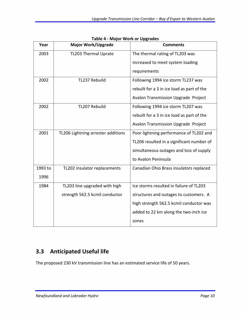
Table 4 ‐ Major Work or Upgrades
Year Major Work/Upgrade Comments
2003 TL203 Thermal Uprate The thermal rating of TL203 was
increased to meet system loading
requirements
2002 TL237 Rebuild Following 1994 ice storm TL237 was
rebuilt for a 3 in ice load as part of the
Avalon Transmission Upgrade Project
2002 TL207 Rebuild Following 1994 ice storm TL207 was
rebuilt for a 3 in ice load as part of the
Avalon Transmission Upgrade Project
2001 TL206 Lightning arrester additions Poor lightning performance of TL202 and
TL206 resulted in a significant number of
simultaneous outages and loss of supply
to Avalon Peninsula
1993 to
1996
TL202 insulator replacements Canadian Ohio Brass insulators replaced
1984 TL203 line upgraded with high
strength 562.5 kcmil conductor
Ice storms resulted in failure of TL203
structures and outages to customers. A
high strength 562.5 kcmil conductor was
added to 22 km along the two‐inch ice
zones
3.3 Anticipated Useful life
The proposed 230 kV transmission line has an estimated service life of 50 years.
Upgrade Transmission Line Corridor – Bay d’Espoir to Western Avalon
Newfoundland and Labrador Hydro Page 11
3.4 Maintenance History
As the proposed 230 kV transmission line between Bay d’Espoir and Western Avalon is a
new asset, there is no maintenance history.
3.5 Outage Statistics
As the proposed 230 kV transmission line between Bay d’Espoir and Western Avalon is a
new asset, there are no available outage statistics. Given the application of an overhead
ground wire along its entire length, it is anticipated that the lightning performance of the
new line will be very similar to that of TL206 which is equipped with lightning arresters. The
mechanical and structural performance of the proposed line will be very similar to that of
TL202, TL206, TL207 and TL237 as it will be designed withstand comparable meteorological
loading.
Outage statistics for existing 230 kV transmission lines in the Bay d’Espoir to Western
Avalon corridor are as follows:
Upgrade Transmission Line Corridor – Bay d’Espoir to Western Avalon
Newfoundland and Labrador Hydro Page 12
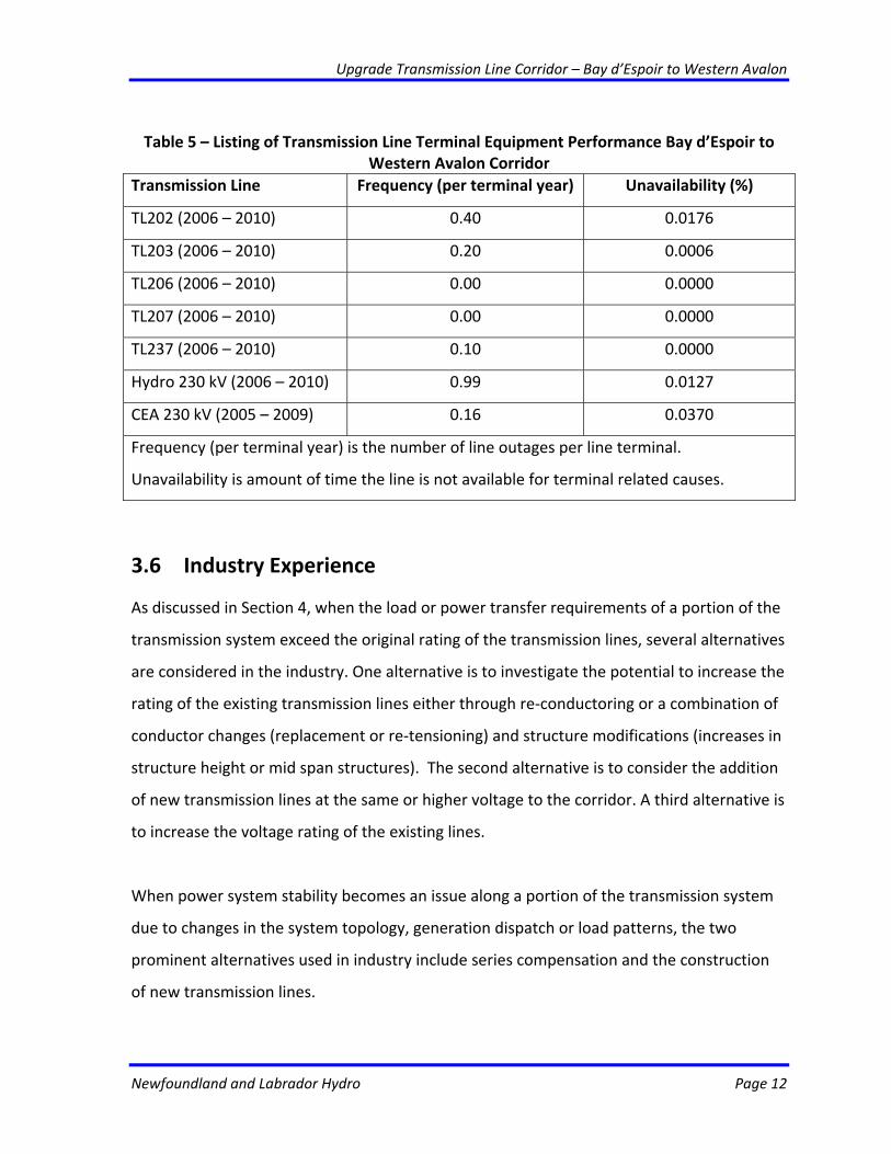
Table 5 – Listing of Transmission Line Terminal Equipment Performance Bay d’Espoir to
Western Avalon Corridor Transmission Line Frequency (per terminal year) Unavailability (%)
TL202 (2006 – 2010) 0.40 0.0176
TL203 (2006 – 2010) 0.20 0.0006
TL206 (2006 – 2010) 0.00 0.0000
TL207 (2006 – 2010) 0.00 0.0000
TL237 (2006 – 2010) 0.10 0.0000
Hydro 230 kV (2006 – 2010) 0.99 0.0127
CEA 230 kV (2005 – 2009) 0.16 0.0370
Frequency (per terminal year) is the number of line outages per line terminal.
Unavailability is amount of time the line is not available for terminal related causes.
3.6 Industry Experience
As discussed in Section 4, when the load or power transfer requirements of a portion of the
transmission system exceed the original rating of the transmission lines, several alternatives
are considered in the industry. One alternative is to investigate the potential to increase the
rating of the existing transmission lines either through re‐conductoring or a combination of
conductor changes (replacement or re‐tensioning) and structure modifications (increases in
structure height or mid span structures). The second alternative is to consider the addition
of new transmission lines at the same or higher voltage to the corridor. A third alternative is
to increase the voltage rating of the existing lines.
When power system stability becomes an issue along a portion of the transmission system
due to changes in the system topology, generation dispatch or load patterns, the two
prominent alternatives used in industry include series compensation and the construction
of new transmission lines.
Upgrade Transmission Line Corridor – Bay d’Espoir to Western Avalon
Newfoundland and Labrador Hydro Page 13
Series compensation involves the addition of a capacitor bank in series with the
transmission line to effectively reduce its impedance. This reduction allows for the
“stiffening” of the transmission network and improves stability. This technique is used
extensively by Hydro‐Québec TransÉnergie to increase the transmission capacity of their
735 kV network. Series compensation on the 735 kV network ranges from 16% to 50%.
The other alternative to improve power system stability is to increase the number of
transmission lines and/or voltage levels in a corridor. Like series compensation, the
construction of parallel lines allow reduces the overall transmission corridor impedance and
thereby “stiffens” the transmission network so that it is no longer susceptible to instability.
When both transmission line ratings and power system stability issues occur along the same
transmission corridor, series compensation, in and of itself, is not an effective solution on its
own.
3.7 Maintenance or Support Arrangements
Normal routine maintenance work for the proposed 230 kV transmission line and
associated terminal station equipment will be performed by Hydro personnel.
3.8 Vendor Recommendations
This project includes the purchase and installation of new terminal station equipment and
the design and construction of a new 230 kV transmission line. Therefore vendor
recommendation with respect to repair or replacement is not pertinent.
3.9 Availability of Replacement Parts
Required spare parts for terminal station equipment and transmission structure
Upgrade Transmission Line Corridor – Bay d’Espoir to Western Avalon
Newfoundland and Labrador Hydro Page 14
components will be purchased at the time of the equipment purchases.
3.11 Retirements
There will be no retirements as part of this project.
3.12 Safety Performance
This project is not required to comply with any specific safety regulation.
3.13 Environmental Performance
This project is not required to address any non‐compliance issues pertaining to
environmental regulations.
3.14 Operating Regime
The proposed 230 kV transmission line and associated terminal station equipment will be
placed in service on a continuous basis, being removed only for regularly scheduled
maintenance.
Upgrade Transmission Line Corridor – Bay d’Espoir to Western Avalon
Newfoundland and Labrador Hydro Page 15
4 JUSTIFICATION
As indicated in Section 1, significant development east of Bay d’Espoir, particularly on the
Avalon Peninsula has resulted in a shift in the province’s load distribution. As a result of this
shift, the limited transmission capacity east of Bay d’Espoir has become the governing factor
for determining the total firm capacity of the Newfoundland and Labrador Hydro
Transmission System. This limitation is demonstrated in a contingency scenario involving
the loss of a unit at Holyrood over peak. As indicated in the load flow analyses below, this
worst‐case scenario would put a significant strain on the Bay d’Espoir East transmission
system. It should also be noted that the duration of the contingency could be quite
extensive if a unit at Holyrood were to be damaged or otherwise out of service.
Existing System
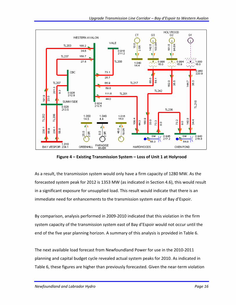
For the existing system, the contingency involving the loss of a unit a Holyrood is illustrated
in Figure 4 where a limit of approximately 854 MW is delivered to loads east of Bay d’Espoir.
As indicated in the figure, the absolute limit of the transmission system is reached in this
case with gas turbines at Holyrood, Hardwoods, and the Newfoundland Power unit at
Greenhill brought online for support.
It should be noted that the loss of the Holyrood unit does not result in the overloading of
transmission lines in this case. Rather, the loss of the unit results in a lack of reactive power
support on the Avalon Peninsula. As illustrated, Holyrood Units 2 and 3 are generating 94.8
Mvar and 103.8 Mvar, respectively, which equals their reactive power limits. If system load
were to increase, these units would no longer be able to meet the reactive power
consumption of the load, and the system would experience a voltage collapse.
Upgrade Transmission Line Corridor – Bay d’Espoir to Western Avalon
Newfoundland and Labrador Hydro Page 16
Figure 4 – Existing Transmission System – Loss of Unit 1 at Holyrood
As a result, the transmission system would only have a firm capacity of 1280 MW. As the
forecasted system peak for 2012 is 1353 MW (as indicated in Section 4.6), this would result
in a significant exposure for unsupplied load. This result would indicate that there is an
immediate need for enhancements to the transmission system east of Bay d’Espoir.
By comparison, analysis performed in 2009‐2010 indicated that this violation in the firm
system capacity of the transmission system east of Bay d’Espoir would not occur until the
end of the five year planning horizon. A summary of this analysis is provided in Table 6.
The next available load forecast from Newfoundland Power for use in the 2010‐2011
planning and capital budget cycle revealed actual system peaks for 2010. As indicated in
Table 6, these figures are higher than previously forecasted. Given the near‐term violation
Upgrade Transmission Line Corridor – Bay d’Espoir to Western Avalon
Newfoundland and Labrador Hydro Page 17
of the firm transmission capacity criterion, a detailed investigation was performed to
identify acceptable transmission system alternatives that will meet all technical
requirements.
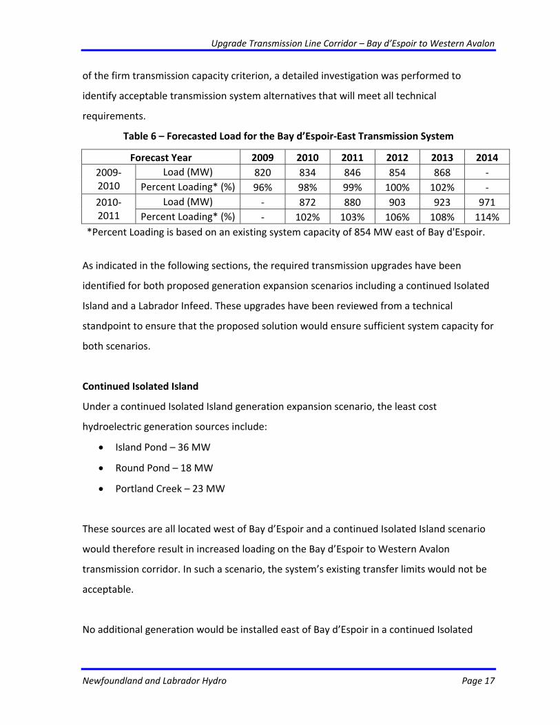
Table 6 – Forecasted Load for the Bay d’Espoir‐East Transmission System
Forecast Year 2009 2010 2011 2012 2013 2014 Load (MW) 820 834 846 854 868 ‐ 2009‐
2010 Percent Loading* (%) 96% 98% 99% 100% 102% ‐ Load (MW) ‐ 872 880 903 923 971 2010‐
2011 Percent Loading* (%) ‐ 102% 103% 106% 108% 114% *Percent Loading is based on an existing system capacity of 854 MW east of Bay d'Espoir.
As indicated in the following sections, the required transmission upgrades have been
identified for both proposed generation expansion scenarios including a continued Isolated
Island and a Labrador Infeed. These upgrades have been reviewed from a technical
standpoint to ensure that the proposed solution would ensure sufficient system capacity for
both scenarios.
Continued Isolated Island
Under a continued Isolated Island generation expansion scenario, the least cost
hydroelectric generation sources include:
• Island Pond – 36 MW
• Round Pond – 18 MW
• Portland Creek – 23 MW
These sources are all located west of Bay d’Espoir and a continued Isolated Island scenario
would therefore result in increased loading on the Bay d’Espoir to Western Avalon
transmission corridor. In such a scenario, the system’s existing transfer limits would not be
acceptable.
No additional generation would be installed east of Bay d’Espoir in a continued Isolated
Upgrade Transmission Line Corridor – Bay d’Espoir to Western Avalon
Newfoundland and Labrador Hydro Page 18
Island scenario until the 2022 timeframe when a 170 MW combined‐cycle combustion
turbine (CCCT) would be installed on the Avalon Peninsula. Transmission upgrades are
therefore required. Alternatives for the transmission system East of Bay d’Espoir include:
(1) Performing thermal upgrades on TL202, TL206 and TL203;
(2) Installing series compensation on TL202 and TL206;
(3) Constructing a new 230 kV transmission line from Bay d’Espoir to Western
Avalon Terminal Station;
(4) Installing shunt capacitor banks;
(5) Performing thermal upgrades on TL202, TL206 and TL203, installing series
compensation on TL202 and TL206, and installing shunt capacitor banks;
(6) Constructing a new 230 kV transmission line from Bay d’Espoir to Western
Avalon Terminal Station and installing shunt capacitor banks;
(7) Adding a 315 kV transmission line; or
(8) Adding a 315 kV transmission line and installing shunt capacitor banks.
A proposal involving only thermal upgrades on TL202, TL206 and TL203 would not improve
system capacity. As demonstrated in Figure 4, system limitations for the contingency
involving the loss of Holyrood Unit 1 relate primarily to reactive support on the Avalon
Peninsula. Solutions involving thermal upgrades alone are only applicable after sufficient
reactive power compensation has been added to the system and transmission lines become
overloaded at higher system loads.
The installation of series compensation on TL202 and TL206 would help to improve
transmission capacity east of Bay d’Espoir by reducing the amount of reactive power
absorbed by the lines. Using the Hydro‐Québec TransÉnergie system as a benchmark (as
discussed in Section 3.6), an upper limit of 50% series compensation was added to each line.
This level of compensation maximizes the transfer capability of the transmission system.
Upgrade Transmission Line Corridor – Bay d’Espoir to Western Avalon
Newfoundland and Labrador Hydro Page 19
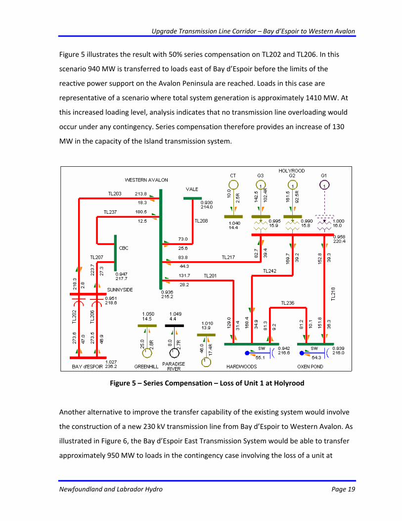
Figure 5 illustrates the result with 50% series compensation on TL202 and TL206. In this
scenario 940 MW is transferred to loads east of Bay d’Espoir before the limits of the
reactive power support on the Avalon Peninsula are reached. Loads in this case are
representative of a scenario where total system generation is approximately 1410 MW. At
this increased loading level, analysis indicates that no transmission line overloading would
occur under any contingency. Series compensation therefore provides an increase of 130
MW in the capacity of the Island transmission system.
Figure 5 – Series Compensation – Loss of Unit 1 at Holyrood
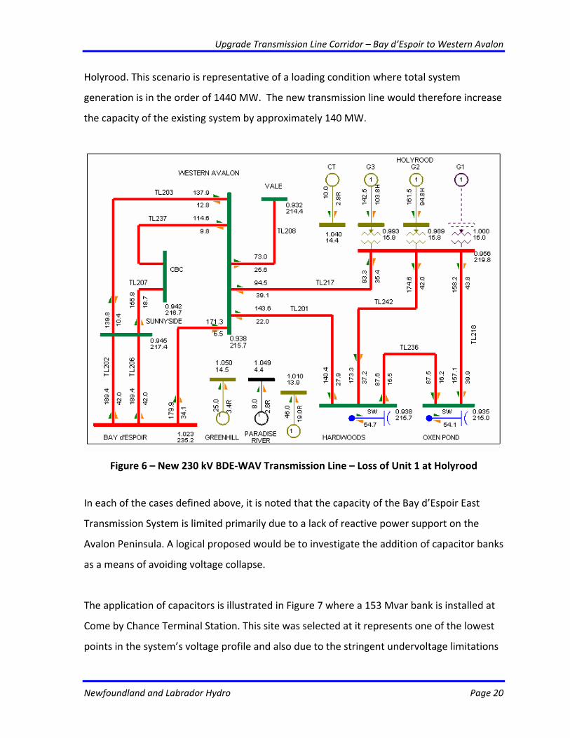
Another alternative to improve the transfer capability of the existing system would involve
the construction of a new 230 kV transmission line from Bay d’Espoir to Western Avalon. As
illustrated in Figure 6, the Bay d’Espoir East Transmission System would be able to transfer
approximately 950 MW to loads in the contingency case involving the loss of a unit at
Upgrade Transmission Line Corridor – Bay d’Espoir to Western Avalon
Newfoundland and Labrador Hydro Page 20
Holyrood. This scenario is representative of a loading condition where total system
generation is in the order of 1440 MW. The new transmission line would therefore increase
the capacity of the existing system by approximately 140 MW.
Figure 6 – New 230 kV BDE‐WAV Transmission Line – Loss of Unit 1 at Holyrood
In each of the cases defined above, it is noted that the capacity of the Bay d’Espoir East
Transmission System is limited primarily due to a lack of reactive power support on the
Avalon Peninsula. A logical proposed would be to investigate the addition of capacitor banks
as a means of avoiding voltage collapse.
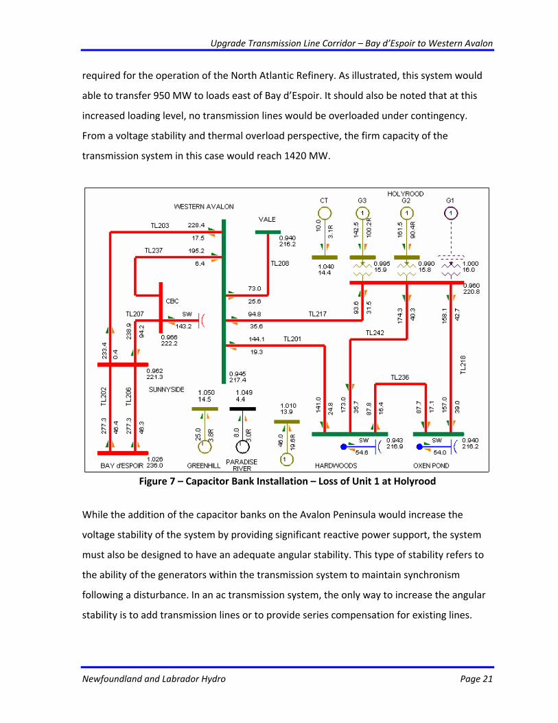
The application of capacitors is illustrated in Figure 7 where a 153 Mvar bank is installed at
Come by Chance Terminal Station. This site was selected at it represents one of the lowest
points in the system’s voltage profile and also due to the stringent undervoltage limitations
Upgrade Transmission Line Corridor – Bay d’Espoir to Western Avalon
Newfoundland and Labrador Hydro Page 21
required for the operation of the North Atlantic Refinery. As illustrated, this system would
able to transfer 950 MW to loads east of Bay d’Espoir. It should also be noted that at this
increased loading level, no transmission lines would be overloaded under contingency.
From a voltage stability and thermal overload perspective, the firm capacity of the
transmission system in this case would reach 1420 MW.
Figure 7 – Capacitor Bank Installation – Loss of Unit 1 at Holyrood
While the addition of the capacitor banks on the Avalon Peninsula would increase the
voltage stability of the system by providing significant reactive power support, the system
must also be designed to have an adequate angular stability. This type of stability refers to
the ability of the generators within the transmission system to maintain synchronism
following a disturbance. In an ac transmission system, the only way to increase the angular
stability is to add transmission lines or to provide series compensation for existing lines.
Upgrade Transmission Line Corridor – Bay d’Espoir to Western Avalon
Newfoundland and Labrador Hydro Page 22
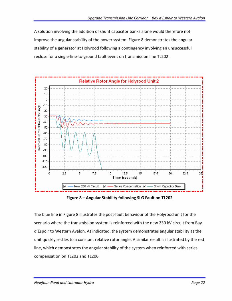
A solution involving the addition of shunt capacitor banks alone would therefore not
improve the angular stability of the power system. Figure 8 demonstrates the angular
stability of a generator at Holyrood following a contingency involving an unsuccessful
reclose for a single‐line‐to‐ground fault event on transmission line TL202.
Figure 8 – Angular Stability following SLG Fault on TL202
The blue line in Figure 8 illustrates the post‐fault behaviour of the Holyrood unit for the
scenario where the transmission system is reinforced with the new 230 kV circuit from Bay
d’Espoir to Western Avalon. As indicated, the system demonstrates angular stability as the
unit quickly settles to a constant relative rotor angle. A similar result is illustrated by the red
line, which demonstrates the angular stability of the system when reinforced with series
compensation on TL202 and TL206.
Upgrade Transmission Line Corridor – Bay d’Espoir to Western Avalon
Newfoundland and Labrador Hydro Page 23
The green line in Figure 8 indicates that the system is highly unstable in a scenario where
only shunt capacitor banks are added to the transmission system. Following the fault, the
unit at Holyrood would begin to oscillate uncontrollably and would have to be tripped to
avoid damage. This situation would then require underfrequency load shedding in an
attempt to prevent the collapse of the Island Transmission System. Due to the poor angular
stability of this system, a solution involving the addition of a shunt capacitor bank alone
would not be an acceptable solution.
Based on the analysis, it is evident that in order to increase the capacity of the Bay d’Espoir
East Transmission System, both voltage stability and the angular stability must be improved.
As noted, a combination of transmission line reinforcement and reactive support in the
form of capacitor banks would provide an optimal solution.
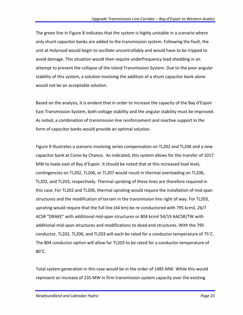
Figure 9 illustrates a scenario involving series compensation on TL202 and TL206 and a new
capacitor bank at Come by Chance. As indicated, this system allows for the transfer of 1017
MW to loads east of Bay d’Espoir. It should be noted that at this increased load level,
contingencies on TL202, TL206, or TL207 would result in thermal overloading on TL206,
TL202, and TL203, respectively. Thermal uprating of these lines are therefore required in
this case. For TL202 and TL206, thermal uprating would require the installation of mid‐span
structures and the modification of terrain in the transmission line right of way. For TL203,
uprating would require that the full line (44 km) be re‐conductored with 795 kcmil, 26/7
ACSR “DRAKE” with additional mid‐span structures or 804 kcmil 54/19 AACSR/TW with
additional mid‐span structures and modifications to dead‐end structures. With the 795
conductor, TL202, TL206, and TL203 will each be rated for a conductor temperature of 75˚C.
The 804 conductor option will allow for TL203 to be rated for a conductor temperature of
80˚C.
Total system generation in this case would be in the order of 1485 MW. While this would
represent an increase of 235 MW in firm transmission system capacity over the existing
Upgrade Transmission Line Corridor – Bay d’Espoir to Western Avalon
Newfoundland and Labrador Hydro Page 24
system, this solution would not be adequate to meet capacity requirements beyond 2017.
As additional generating capacity would not be added east of Bay d’Espoir until 2022, this
solution would not provide an acceptable technical alternative.
Figure 9 – Series Compensation, Thermal Upgrades, and Capacitor Bank
Loss of Unit 1 at Holyrood
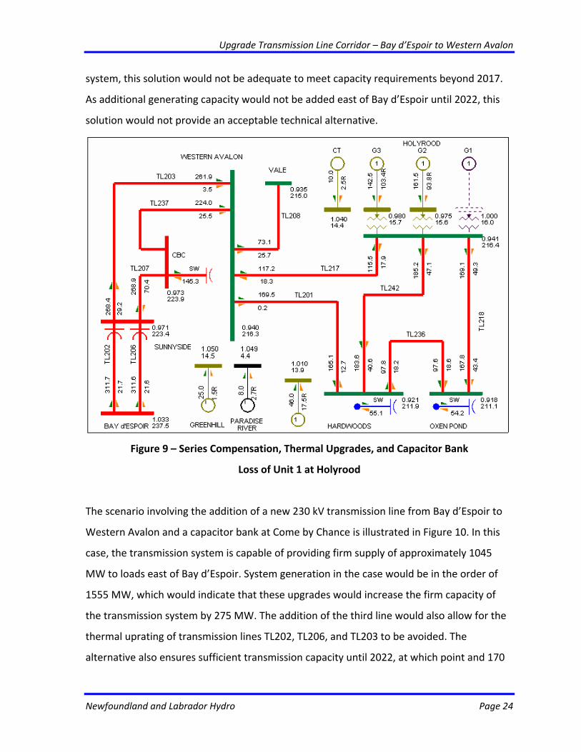
The scenario involving the addition of a new 230 kV transmission line from Bay d’Espoir to
Western Avalon and a capacitor bank at Come by Chance is illustrated in Figure 10. In this
case, the transmission system is capable of providing firm supply of approximately 1045
MW to loads east of Bay d’Espoir. System generation in the case would be in the order of
1555 MW, which would indicate that these upgrades would increase the firm capacity of
the transmission system by 275 MW. The addition of the third line would also allow for the
thermal uprating of transmission lines TL202, TL206, and TL203 to be avoided. The
alternative also ensures sufficient transmission capacity until 2022, at which point and 170
Upgrade Transmission Line Corridor – Bay d’Espoir to Western Avalon
Newfoundland and Labrador Hydro Page 25
MW of generation would be available on the Avalon Peninsula following the construction of
a new 170 MW CCCT.
Figure 10 – New 230 kV TL and Capacitor Bank – Loss of Unit 1 at Holyrood
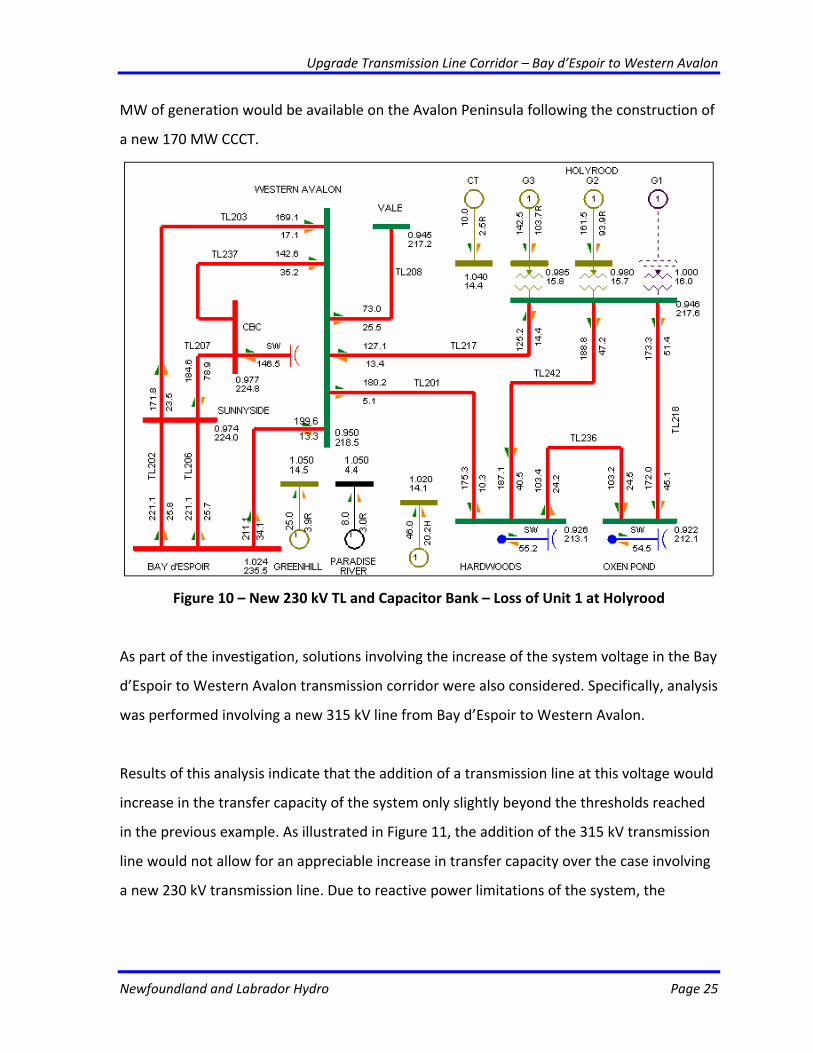
As part of the investigation, solutions involving the increase of the system voltage in the Bay
d’Espoir to Western Avalon transmission corridor were also considered. Specifically, analysis
was performed involving a new 315 kV line from Bay d’Espoir to Western Avalon.
Results of this analysis indicate that the addition of a transmission line at this voltage would
increase in the transfer capacity of the system only slightly beyond the thresholds reached
in the previous example. As illustrated in Figure 11, the addition of the 315 kV transmission
line would not allow for an appreciable increase in transfer capacity over the case involving
a new 230 kV transmission line. Due to reactive power limitations of the system, the
Upgrade Transmission Line Corridor – Bay d’Espoir to Western Avalon
Newfoundland and Labrador Hydro Page 26
transfer limit of the Bay d’Espoir East Transmission System is limited to 950 MW. Firm total
system capacity is therefore limited to approximately 1440 in this case.
Figure 12 – New 315 kV Transmission Line – Loss of Unit 1 at Holyrood
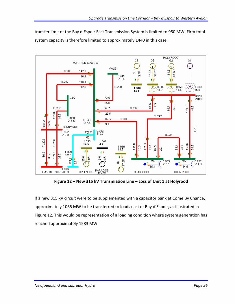
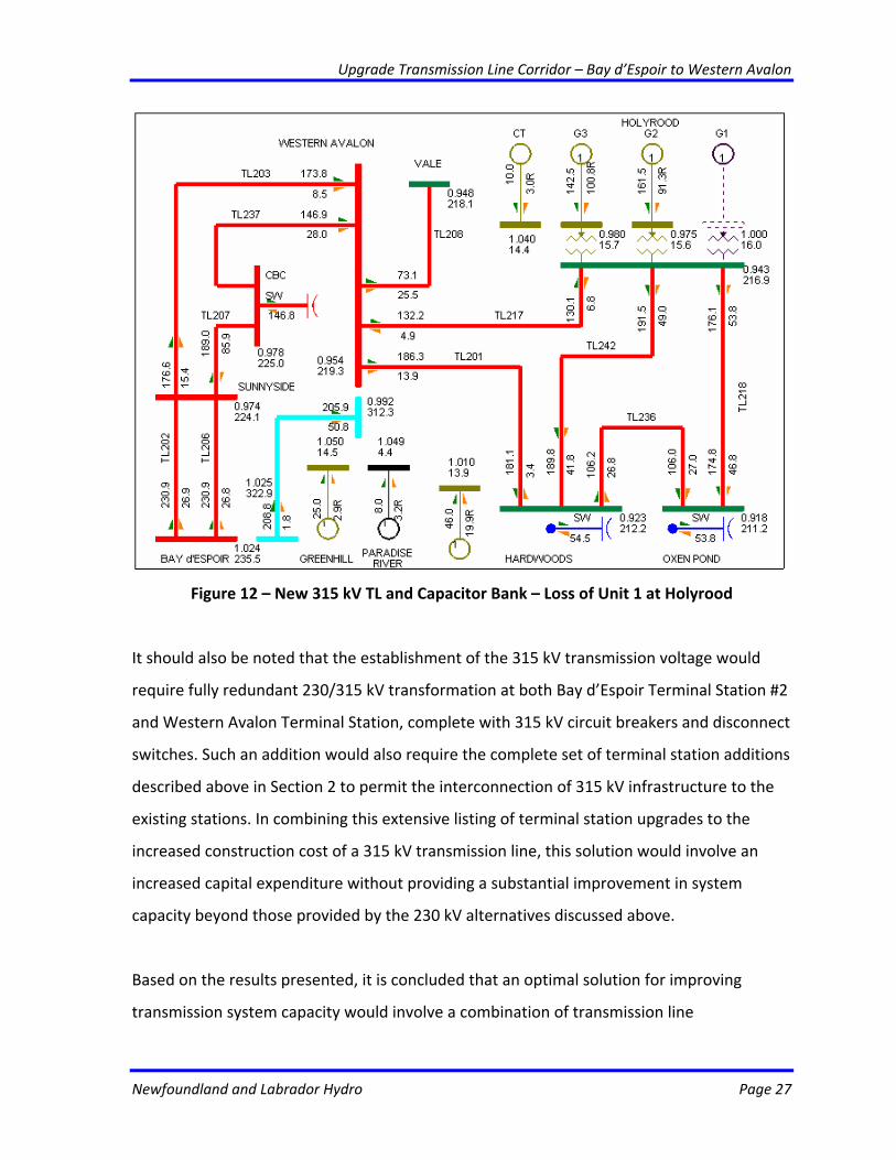
If a new 315 kV circuit were to be supplemented with a capacitor bank at Come By Chance,
approximately 1065 MW to be transferred to loads east of Bay d’Espoir, as illustrated in
Figure 12. This would be representation of a loading condition where system generation has
reached approximately 1583 MW.
Upgrade Transmission Line Corridor – Bay d’Espoir to Western Avalon
Newfoundland and Labrador Hydro Page 27
Figure 12 – New 315 kV TL and Capacitor Bank – Loss of Unit 1 at Holyrood
It should also be noted that the establishment of the 315 kV transmission voltage would
require fully redundant 230/315 kV transformation at both Bay d’Espoir Terminal Station #2
and Western Avalon Terminal Station, complete with 315 kV circuit breakers and disconnect
switches. Such an addition would also require the complete set of terminal station additions
described above in Section 2 to permit the interconnection of 315 kV infrastructure to the
existing stations. In combining this extensive listing of terminal station upgrades to the
increased construction cost of a 315 kV transmission line, this solution would involve an
increased capital expenditure without providing a substantial improvement in system
capacity beyond those provided by the 230 kV alternatives discussed above.
Based on the results presented, it is concluded that an optimal solution for improving
transmission system capacity would involve a combination of transmission line
Upgrade Transmission Line Corridor – Bay d’Espoir to Western Avalon
Newfoundland and Labrador Hydro Page 28
reinforcement and reactive support. A solution involving only reactive support would not be
acceptable due to poor angular stability, while a solution involving only thermal upgrades
would not improve system capacity. Reinforcements in the form of series compensation or
a new transmission line would therefore be required.
Solutions involving the series compensation do not provide sufficient system capacity
beyond 2017 and are not acceptable given that no generation will be added east of Bay
d’Espoir until 2022. Therefore, a new transmission line should be constructed from Bay
d’Espoir to Western Avalon to meet the 2022 transfer requirement. Both the 230 kV and
315 kV transmission line alternatives were considered. It has been determined that
solutions involving 315 kV transmission lines require a significant number of additional
system upgrades while only provided marginal improvements in system capacity. Given this
result, the construction of a new 230 kV transmission line is found to be the optimal
solution for a generation expansion scenario involving the continued Isolated Operation of
the Island System.
Labrador Infeed
Under the Labrador Infeed generation expansion scenario the concept includes a 900 MW
HVdc transmission system between Muskrat Falls in Labrador and Soldiers Pond on the
Avalon Peninsula and a second 500 MW HVdc transmission system between western
Newfoundland (Bottom Brook Terminal Station) and Cape Breton, Nova Scotia. The power
and energy delivered to the Island from Labrador will displace that generated at the
Holyrood Thermal Generating Station. Up to 816 MW will be delivered to the Island over
peak. The HVdc system to the Maritimes will operate as an export line under normal
operation with power and energy in excess of the Province’s needs being sold to the
Maritime and New England markets. For loss of the HVdc system between Labrador and
the Island, the HVdc link to the Maritimes will be capable of delivering up to 475 MW to the
Island in the post contingency period.
Upgrade Transmission Line Corridor – Bay d’Espoir to Western Avalon
Newfoundland and Labrador Hydro Page 29
As part of the preliminary technical feasibility analysis performed for the Lower Churchill
Project, a series of integration studies have included investigations of the upgrades required
within the Island Transmission System to ensure reliability and security of supply for the
Project. In these studies, many contingencies were investigated. A benchmark case was
chosen to assess transient system stability in the event of a three‐phase fault near the 230
kV bus at Sunnyside Terminal Station. This three‐phase fault was identified as being
particularly severe as it would (1) suppress ac system voltages to a point where the HVdc
link from Labrador would experience a commutation failure (effectively causing it to shut
down during the fault), while (2) impacting the transmission of power from hydroelectric
sources to the significant loads in the eastern portion of the province.
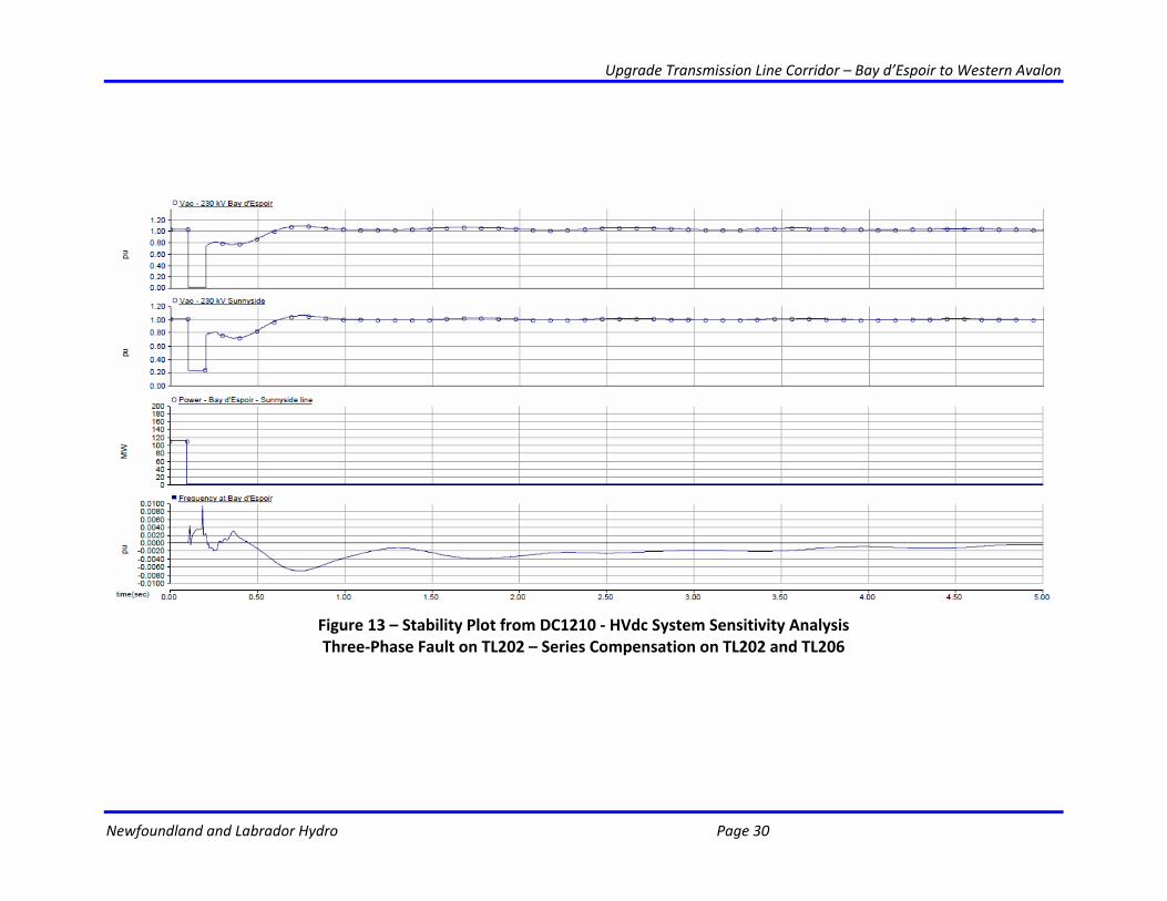
Results of the transient stability studies indicate that the system would be able to withstand
the three‐phase fault at Sunnyside Terminal Station with appropriate system upgrades. The
upgrades include the installation of high‐inertia synchronous condensers and either:
(1) series compensation on TL202 and TL206; or
(2) a new 230 kV transmission line from Bay d’Espoir to Western Avalon Terminal
Station.
Stability plots for the above cases are provide in Figures 13 and 14, respectively.
Upgrade Transmission Line Corridor – Bay d’Espoir to Western Avalon
Newfoundland and Labrador Hydro Page 30
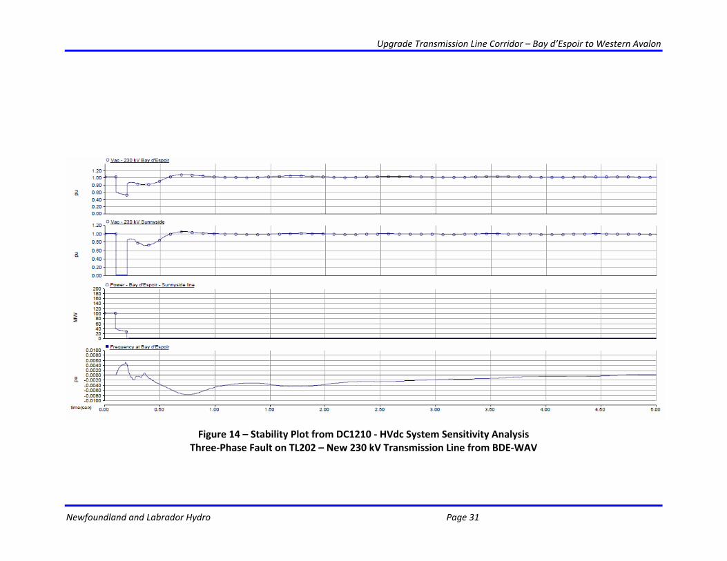
Figure 13 – Stability Plot from DC1210 ‐ HVdc System Sensitivity Analysis Three‐Phase Fault on TL202 – Series Compensation on TL202 and TL206
Upgrade Transmission Line Corridor – Bay d’Espoir to Western Avalon
Newfoundland and Labrador Hydro Page 31
Figure 14 – Stability Plot from DC1210 ‐ HVdc System Sensitivity Analysis Three‐Phase Fault on TL202 – New 230 kV Transmission Line from BDE‐WAV
Upgrade Transmission Line Corridor – Bay d’Espoir to Western Avalon
Newfoundland and Labrador Hydro Page 32
While each of these alternatives ensures transient stability for specified 230 kV system
contingencies, the transmission capacity of the Bay d’Espoir to Western Avalon corridor also
has a significant impact in a scenario involving the loss of the HVdc link between Labrador
and the Island. For this contingency, power will be imported from the Maritimes to
supplement the startup of standby generation on the Island.
As in the continued Isolated Operation, Island System upgrades consisting of series
compensation for transmission lines TL202 and TL206 will increase the angular stability of
the power system, as illustrated in Figure 13. However, unlike the continued Isolated
Operation scenario, the Holyrood Thermal Generating Station is not available to provide
active power (MW) to the Bay d’Espoir East Transmission System in the Labrador Infeed
Scenario. As a result, contingencies involving the loss of the Labrador Infeed would result
significant overloading on the transmission lines, and therefore require the thermal
uprating of TL202, TL206, and TL203.
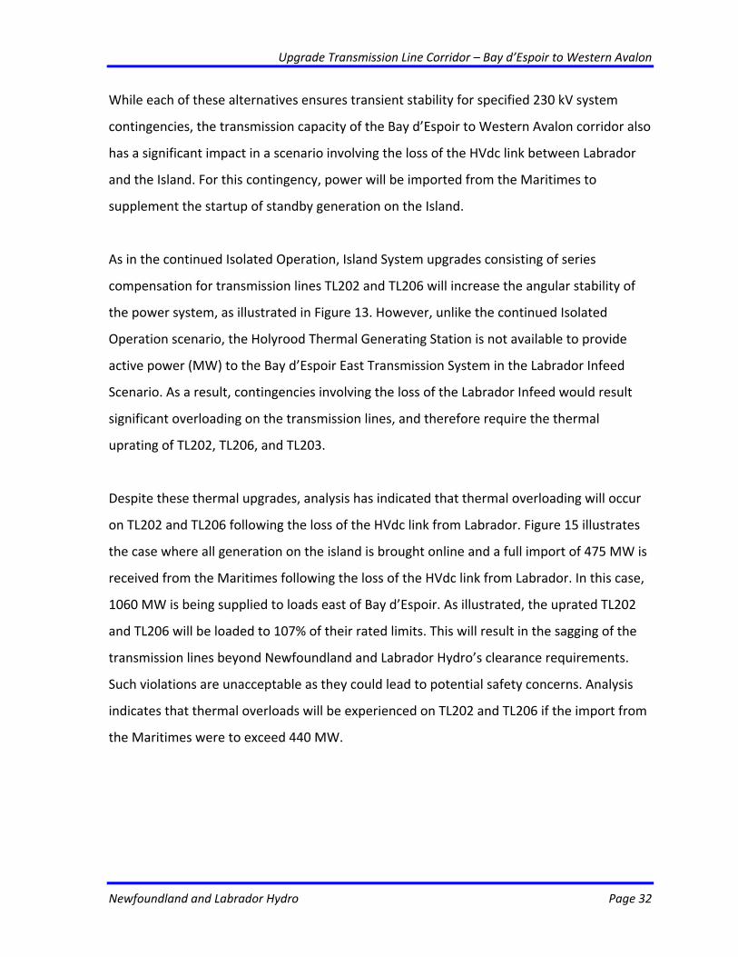
Despite these thermal upgrades, analysis has indicated that thermal overloading will occur
on TL202 and TL206 following the loss of the HVdc link from Labrador. Figure 15 illustrates
the case where all generation on the island is brought online and a full import of 475 MW is
received from the Maritimes following the loss of the HVdc link from Labrador. In this case,
1060 MW is being supplied to loads east of Bay d’Espoir. As illustrated, the uprated TL202
and TL206 will be loaded to 107% of their rated limits. This will result in the sagging of the
transmission lines beyond Newfoundland and Labrador Hydro’s clearance requirements.
Such violations are unacceptable as they could lead to potential safety concerns. Analysis
indicates that thermal overloads will be experienced on TL202 and TL206 if the import from
the Maritimes were to exceed 440 MW.
Upgrade Transmission Line Corridor – Bay d’Espoir to Western Avalon
Newfoundland and Labrador Hydro Page 33
Figure 15 – Thermal Upgrades and Series Compensation – Loss of HVdc Infeed
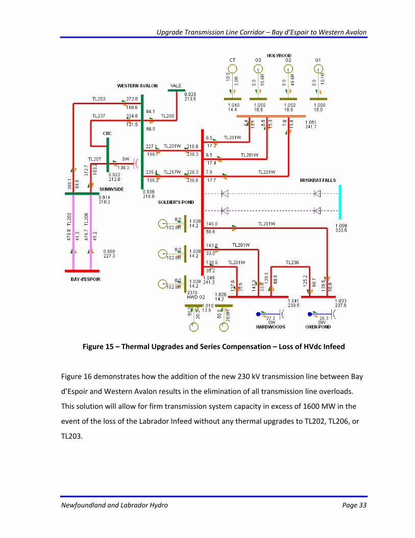
Figure 16 demonstrates how the addition of the new 230 kV transmission line between Bay
d’Espoir and Western Avalon results in the elimination of all transmission line overloads.
This solution will allow for firm transmission system capacity in excess of 1600 MW in the
event of the loss of the Labrador Infeed without any thermal upgrades to TL202, TL206, or
TL203.
Upgrade Transmission Line Corridor – Bay d’Espoir to Western Avalon
Newfoundland and Labrador Hydro Page 34
Figure 16 – New 230 kV Transmission Line – Loss of HVdc Infeed
It should be noted that reactive compensation in the form of a 153 Mvar capacitor bank at
Come by Chance was included in both of the cases described above. Without this capacitor
bank, the system would suffer from low voltage violations in the event of the loss of the
Labrador Infeed. This capacitor bank can be considered part of the overall reactive power
requirements of the HVdc converter station in this scenario.
Based on the analysis, it is concluded that a new 230 kV circuit from Bay d’Espoir to
Western Avalon meets all of the technical requirements for the Labrador Infeed Scenario.
Upgrade Transmission Line Corridor – Bay d’Espoir to Western Avalon
Newfoundland and Labrador Hydro Page 35
This new circuit ensures transient stability during severe ac contingencies and security of
supply in the event of the failure of the HVdc link from Labrador. In order for this
transmission line to be in service prior to the proposed HVdc interconnection in 2017, line
construction must begin in 2012 as per the five‐year project schedule provided in Section
5.2.
Analysis of the thermal upgrades plus 50% series compensation on TL202 and TL206
indicate that the option cannot provide the transfer capacity required to supply the loads
east of Bay d’Espoir in the event of the failure of the HVdc link from Labrador.
4.1 Net Present Value
The construction of a new 230 kV transmission line from Bay d’Espoir to Western Avalon
Terminal Station is a technical requirement needed to meet the forecasted system loads
east of Bay d’Espoir. A complete net present value analysis was not performed as the
project is required in both the Labrador Infeed and continued Isolated Operation generation
expansion alternatives. As a result of being common to both alternatives, the cost of the
project has no relevant impact on overall cumulative present worth.
4.2 Levelized Cost of Energy
The levelized cost of energy is a high level means to compare costs of developing two or
more alternative generating sources. Therefore, the levelized cost of energy is not
applicable for the project.
4.3 Cost Benefit Analysis
The new 230 kV transmission line from Bay d’Espoir to Western Avalon Terminal Station is a
technical requirement needed to meet the forecasted system loads east of Bay d’Espoir. A
complete cost benefit analysis was not performed as the project is common to both the
Upgrade Transmission Line Corridor – Bay d’Espoir to Western Avalon
Newfoundland and Labrador Hydro Page 36
Labrador Infeed and continued Isolated Operation generation expansion scenarios.
4.4 Legislative or Regulatory Requirements
This project is not required to comply with legislation or regulations. The project is required
to ensure reliable operation of the power system and to supply forecasted loads east of Bay
d’Espoir while adhering to all system planning criteria.
4.5 Historical Information
The proposed project is not routine and is a technical requirement to meet load growth east
of Bay d’Espoir for the Labrador Infeed and continued Isolated Operation generation
expansion scenarios.
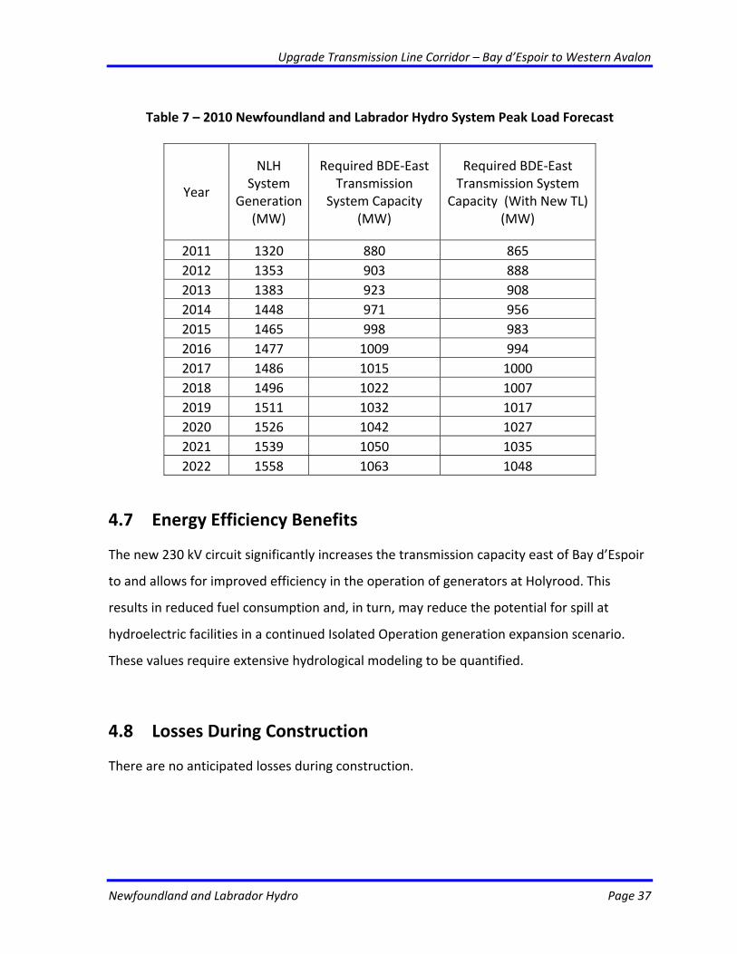
4.6 Forecast Customer Growth
The 2010 Peak Load Forecast for the Newfoundland and Labrador Hydro System is provided
in Table 7. This forecast is equal to the 2010 Peak Load Forecast for the Interconnected
Island System minus generation from Newfoundland Power and Deer Lake Power.
Based upon the peak system load data presented in Table 1, it is estimated that loads east
of Bay d’Espoir will account for approximately 67% of the total system load. These values
have been corrected to account for additional load associated with the Vale facility in Long
Harbour and also for the reduced system losses in cases involving the construction of a new
transmission line from Bay d’Espoir to Western Avalon. This reduction in losses would
effectively decrease the required transfer capacity east of Bay d’Espoir.
Upgrade Transmission Line Corridor – Bay d’Espoir to Western Avalon
Newfoundland and Labrador Hydro Page 37
Table 7 – 2010 Newfoundland and Labrador Hydro System Peak Load Forecast
Year
NLH System
Generation (MW)
Required BDE‐East Transmission
System Capacity (MW)
Required BDE‐East Transmission System
Capacity (With New TL) (MW)
2011 1320 880 865 2012 1353 903 888 2013 1383 923 908 2014 1448 971 956 2015 1465 998 983 2016 1477 1009 994 2017 1486 1015 1000 2018 1496 1022 1007 2019 1511 1032 1017 2020 1526 1042 1027 2021 1539 1050 1035 2022 1558 1063 1048
4.7 Energy Efficiency Benefits
The new 230 kV circuit significantly increases the transmission capacity east of Bay d’Espoir
to and allows for improved efficiency in the operation of generators at Holyrood. This
results in reduced fuel consumption and, in turn, may reduce the potential for spill at
hydroelectric facilities in a continued Isolated Operation generation expansion scenario.
These values require extensive hydrological modeling to be quantified.
4.8 Losses During Construction
There are no anticipated losses during construction.
Upgrade Transmission Line Corridor – Bay d’Espoir to Western Avalon
Newfoundland and Labrador Hydro Page 38
4.9 Status Quo
A solution involving the status quo would not be acceptable for generation expansion
scenarios involving a Labrador Infeed or continued Isolated Operation.
In a generation expansion scenario involving the Labrador Infeed, the existing transmission
system must be reinforced to maintain stability in the event of contingencies on the 230 kV
system. Upgrades to the Bay d’Espoir East Transmission System are also required to ensure
security of supply in the event of contingencies involving the loss of the Labrador Infeed via
import from the Maritimes.
For a generation expansion scenario involving continued Isolated Operation, the limitations
of the existing transmission system result in an inadequate transfer capacity for loads east
of Bay d’Espoir. This is of particular concern as all proposed hydroelectric developments in
this scenario are west of Bay d’Espoir.
4.10 Alternatives
Alternatives considered for this project include:
(1) Performing thermal upgrades on TL202, TL206 and TL203;
(2) Installing series compensation on TL202 and TL206;
(3) Constructing a new 230 kV transmission line from Bay d’Espoir to Western
Avalon Terminal Station;
(4) Installing shunt capacitor banks;
(5) Performing thermal upgrades on TL202, TL206 and TL203, installing series
compensation on TL202 and TL206, and installing shunt capacitor banks;
(6) Constructing a new 230 kV transmission line from Bay d’Espoir to Western
Avalon Terminal Station and installing shunt capacitor banks;
(7) Adding a 315 kV transmission line ; or
Upgrade Transmission Line Corridor – Bay d’Espoir to Western Avalon
Newfoundland and Labrador Hydro Page 39
(8) Adding a 315 kV transmission line and installing shunt capacitor banks.
Based upon the analysis in Section 4, a new 230 kV transmission line from Bay d’Espoir to
Western Avalon Terminal Station (supplemented with reactive support in the form of shunt
capacitor banks) is the preferred alternative for generation expansion scenarios involving
both the Labrador Infeed and continued Isolated Operation.
Upgrade Transmission Line Corridor – Bay d’Espoir to Western Avalon
Newfoundland and Labrador Hydro Page 40
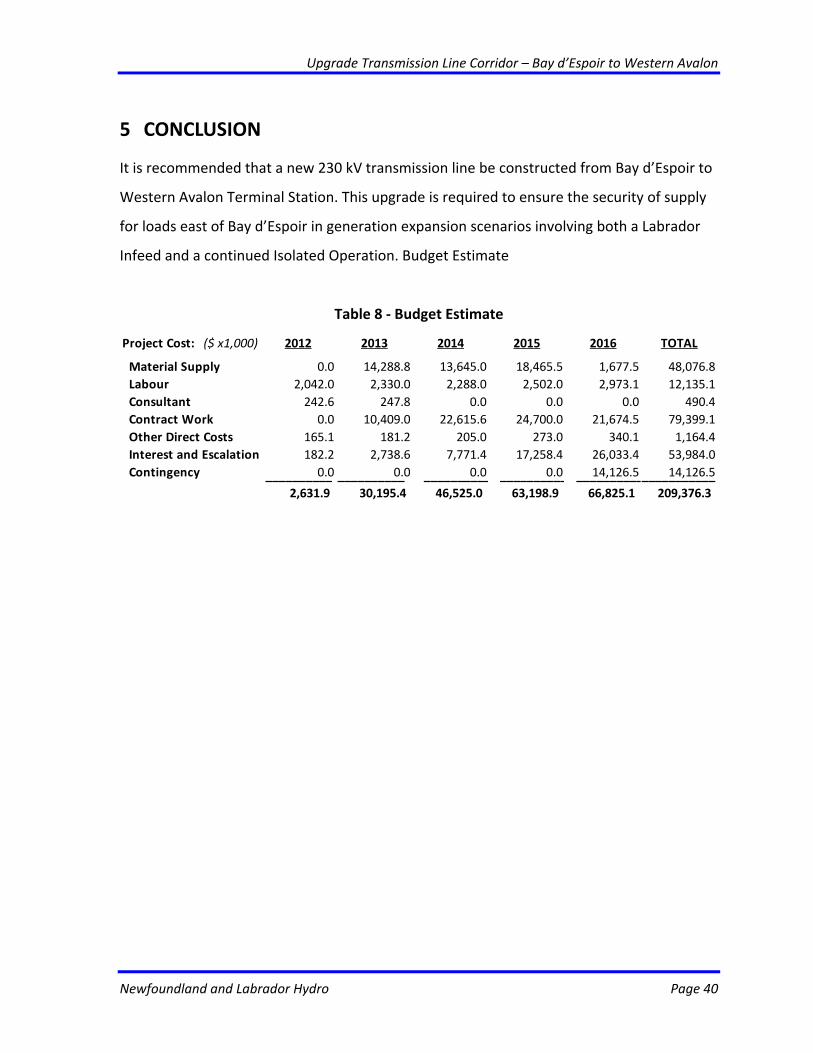
5 CONCLUSION
It is recommended that a new 230 kV transmission line be constructed from Bay d’Espoir to
Western Avalon Terminal Station. This upgrade is required to ensure the security of supply
for loads east of Bay d’Espoir in generation expansion scenarios involving both a Labrador
Infeed and a continued Isolated Operation. Budget Estimate
Table 8 ‐ Budget Estimate
Project Cost: ($ x1,000) 2012 2013 2014 2015 2016 TOTAL
Material Supply 0.0 14,288.8 13,645.0 18,465.5 1,677.5 48,076.8 Labour 2,042.0 2,330.0 2,288.0 2,502.0 2,973.1 12,135.1 Consultant 242.6 247.8 0.0 0.0 0.0 490.4 Contract Work 0.0 10,409.0 22,615.6 24,700.0 21,674.5 79,399.1 Other Direct Costs 165.1 181.2 205.0 273.0 340.1 1,164.4 Interest and Escalation 182.2 2,738.6 7,771.4 17,258.4 26,033.4 53,984.0 Contingency 0.0 0.0 0.0 0.0 14,126.5 14,126.5 __________ __________ __________ __________ ______________________
2,631.9 30,195.4 46,525.0 63,198.9 66,825.1 209,376.3

Upgrade Transmission Line Corridor – Bay d’Espoir to Western Avalon
Newfoundland and Labrador Hydro Page 41
5.2 Project Schedule
Table 9 ‐ Project Schedule: Year 1 ‐ 2012
Activity Start Date End Date
Insulator
Testing
• Perform Testing of NEMA insulators Apr. 2012
Aug. 2012
Planning • Determine Outage Schedule (as Required)
• Survey TL Corridor and Terminal Stations
Jan. 2012
Jun. 2012
Mar. 2012
Aug. 2012
Design • Preliminary Design, Structure Layouts Apr. 2012 Aug. 2012
Procurement • Tendering and Award Apr. 2012 Nov. 2012
Construction • Environmental Assessment and Draft
Results
Jun. 2012 Aug. 2012
Commissioning • Environmental Assessment Final Report Nov. 2012 Nov. 2012
Closeout • Update Design Data Dec. 2012 Dec. 2012
Upgrade Transmission Line Corridor – Bay d’Espoir to Western Avalon
Newfoundland and Labrador Hydro Page 42
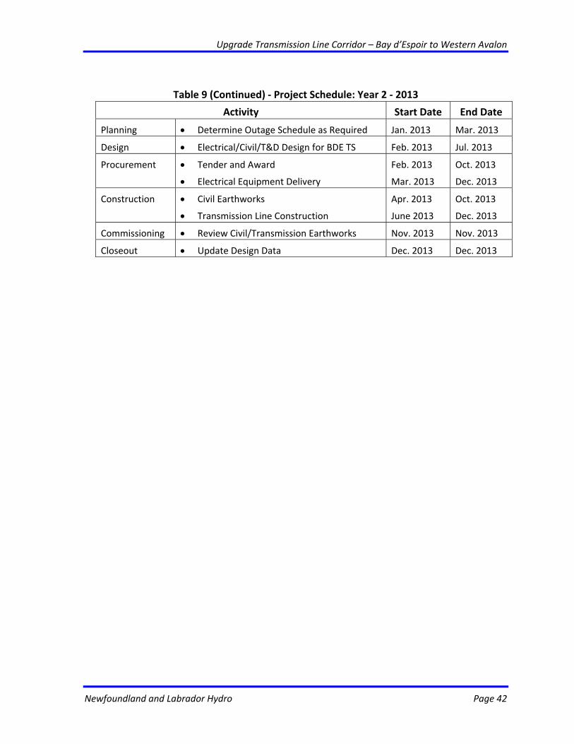
Table 9 (Continued) ‐ Project Schedule: Year 2 ‐ 2013
Activity Start Date End Date
Planning • Determine Outage Schedule as Required Jan. 2013 Mar. 2013
Design • Electrical/Civil/T&D Design for BDE TS Feb. 2013 Jul. 2013
Procurement • Tender and Award
• Electrical Equipment Delivery
Feb. 2013
Mar. 2013
Oct. 2013
Dec. 2013
Construction • Civil Earthworks
• Transmission Line Construction
Apr. 2013
June 2013
Oct. 2013
Dec. 2013
Commissioning • Review Civil/Transmission Earthworks Nov. 2013 Nov. 2013
Closeout • Update Design Data Dec. 2013 Dec. 2013
Upgrade Transmission Line Corridor – Bay d’Espoir to Western Avalon
Newfoundland and Labrador Hydro Page 43
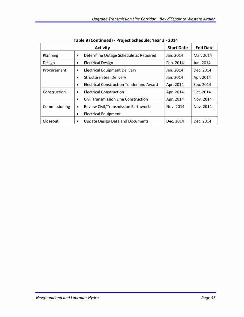
Table 9 (Continued) ‐ Project Schedule: Year 3 ‐ 2014
Activity Start Date End Date
Planning • Determine Outage Schedule as Required Jan. 2014 Mar. 2014
Design • Electrical Design Feb. 2014 Jun. 2014
Procurement • Electrical Equipment Delivery
• Structure Steel Delivery
• Electrical Construction Tender and Award
Jan. 2014
Jan. 2014
Apr. 2014
Dec. 2014
Apr. 2014
Sep. 2014
Construction • Electrical Construction
• Civil Transmission Line Construction
Apr. 2014
Apr. 2014
Oct. 2014
Nov. 2014
Commissioning • Review Civil/Transmission Earthworks
• Electrical Equipment
Nov. 2014 Nov. 2014
Closeout • Update Design Data and Documents Dec. 2014 Dec. 2014
Upgrade Transmission Line Corridor – Bay d’Espoir to Western Avalon
Newfoundland and Labrador Hydro Page 44
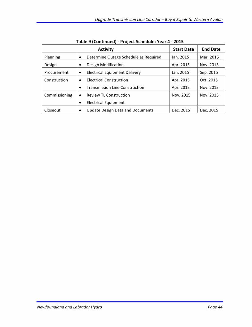
Table 9 (Continued) ‐ Project Schedule: Year 4 ‐ 2015
Activity Start Date End Date
Planning • Determine Outage Schedule as Required Jan. 2015 Mar. 2015
Design • Design Modifications Apr. 2015 Nov. 2015
Procurement • Electrical Equipment Delivery Jan. 2015 Sep. 2015
Construction • Electrical Construction
• Transmission Line Construction
Apr. 2015
Apr. 2015
Oct. 2015
Nov. 2015
Commissioning • Review TL Construction
• Electrical Equipment
Nov. 2015 Nov. 2015
Closeout • Update Design Data and Documents Dec. 2015 Dec. 2015
Upgrade Transmission Line Corridor – Bay d’Espoir to Western Avalon
Newfoundland and Labrador Hydro Page 45
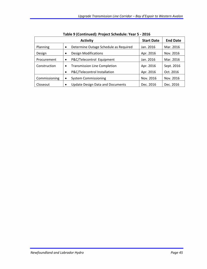
Table 9 (Continued): Project Schedule: Year 5 ‐ 2016
Activity Start Date End Date
Planning • Determine Outage Schedule as Required Jan. 2016 Mar. 2016
Design • Design Modifications Apr. 2016 Nov. 2016
Procurement • P&C/Telecontrol Equipment Jan. 2016 Mar. 2016
Construction • Transmission Line Completion
• P&C/Telecontrol Installation
Apr. 2016
Apr. 2016
Sept. 2016
Oct. 2016
Commissioning • System Commissioning Nov. 2016 Nov. 2016
Closeout • Update Design Data and Documents Dec. 2016 Dec. 2016
Recommended