
1www.esi-group.com
Copyright © ESI Group, 2017. All rights reserved.
www.esi-group.com
Copyright © ESI Group, 2016. All rights reserved.
What’s New in PAM-STAMP 2017.5
Webinar
David Lorenz2017-08-30
2www.esi-group.com
Copyright © ESI Group, 2017. All rights reserved.
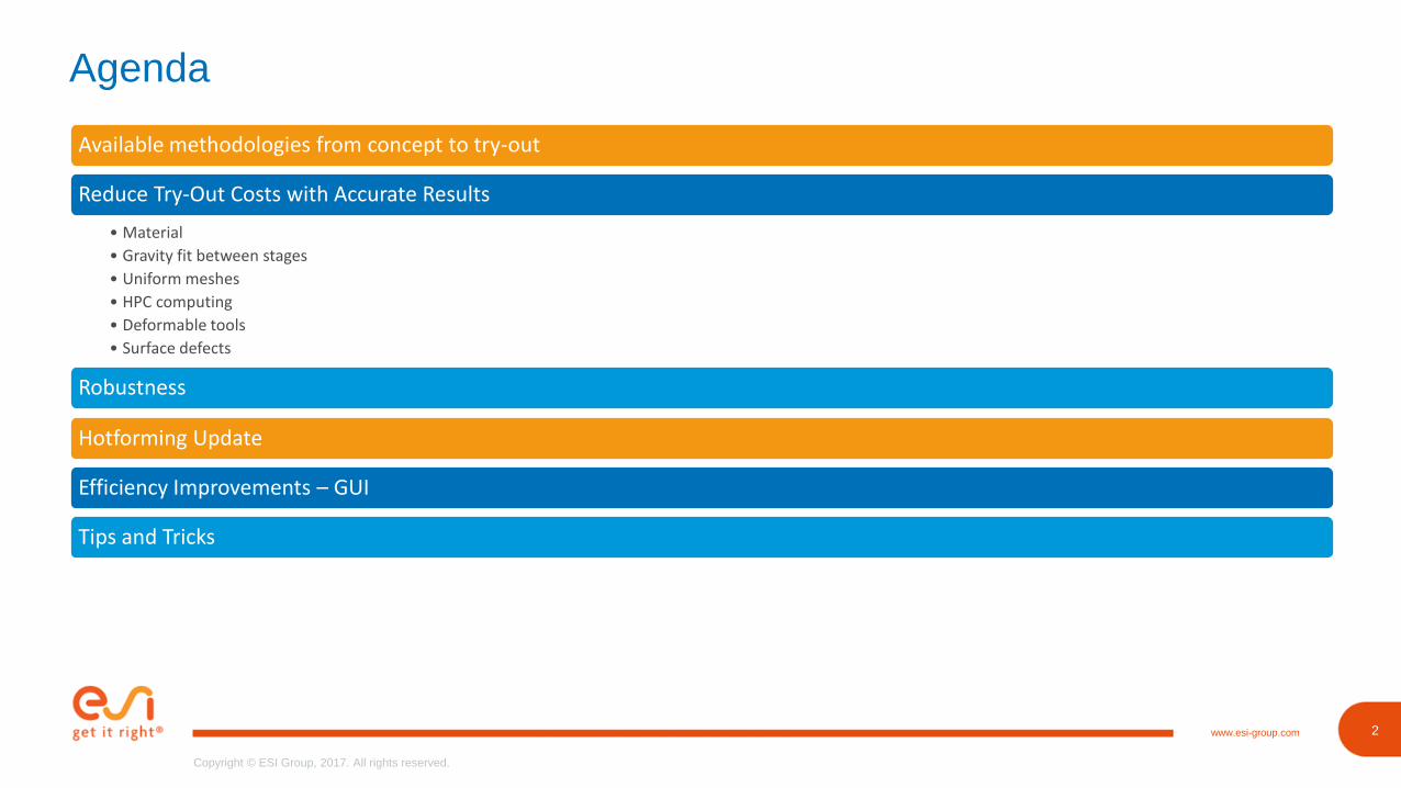
Agenda
Available methodologies from concept to try-out
Reduce Try-Out Costs with Accurate Results
Robustness
• Material
• Gravity fit between stages
• Uniform meshes
• HPC computing
• Deformable tools
• Surface defects Based on accurate results
Hotforming Update
Efficiency Improvements – GUI
Tips and Tricks
3www.esi-group.com
Copyright © ESI Group, 2017. All rights reserved.
3
Copyright © ESI Group, 2017. All rights reserved.
www.esi-group.com
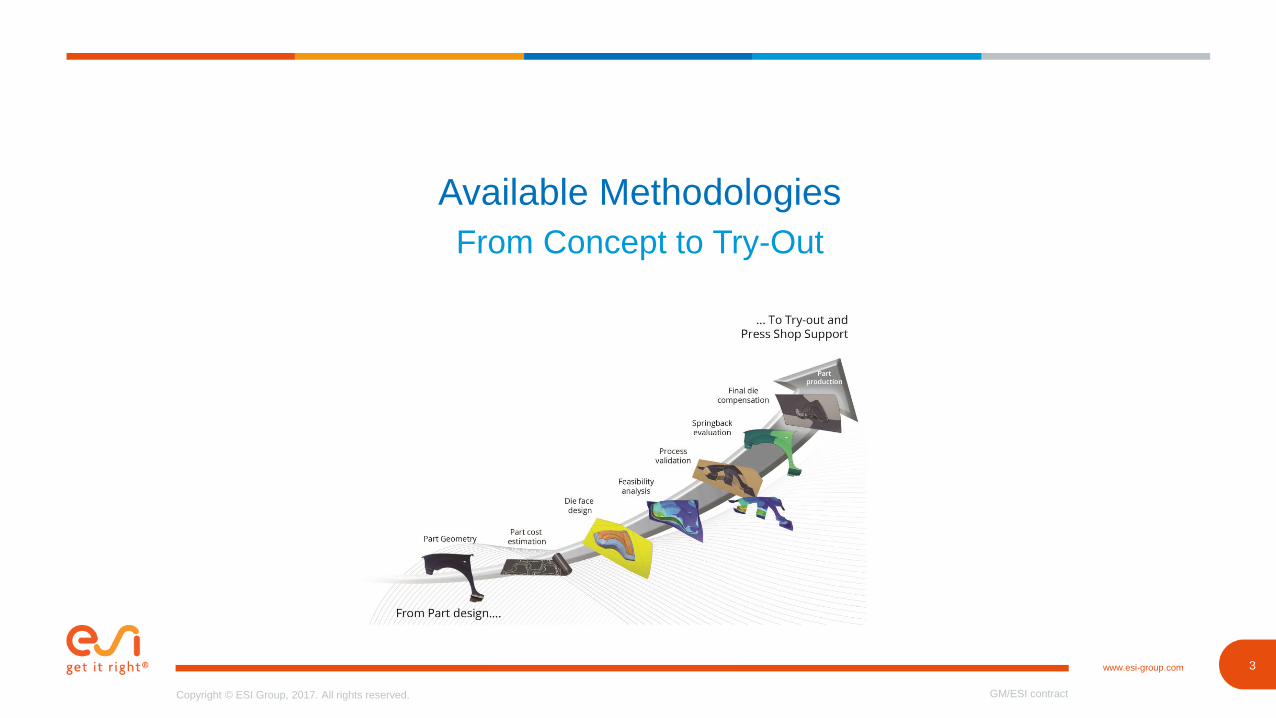
Available Methodologies
From Concept to Try-Out
GM/ESI contract
4www.esi-group.com
Copyright © ESI Group, 2017. All rights reserved.
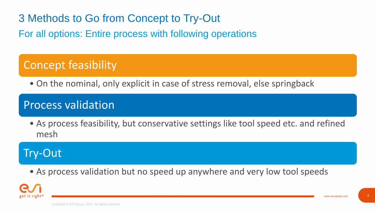
For all options: Entire process with following operations
3 Methods to Go from Concept to Try-Out
Concept feasibility
• On the nominal, only explicit in case of stress removal, else springback
Process validation
• As process feasibility, but conservative settings like tool speed etc. and refined mesh
Try-Out
• As process validation but no speed up anywhere and very low tool speeds
5www.esi-group.com
Copyright © ESI Group, 2017. All rights reserved.
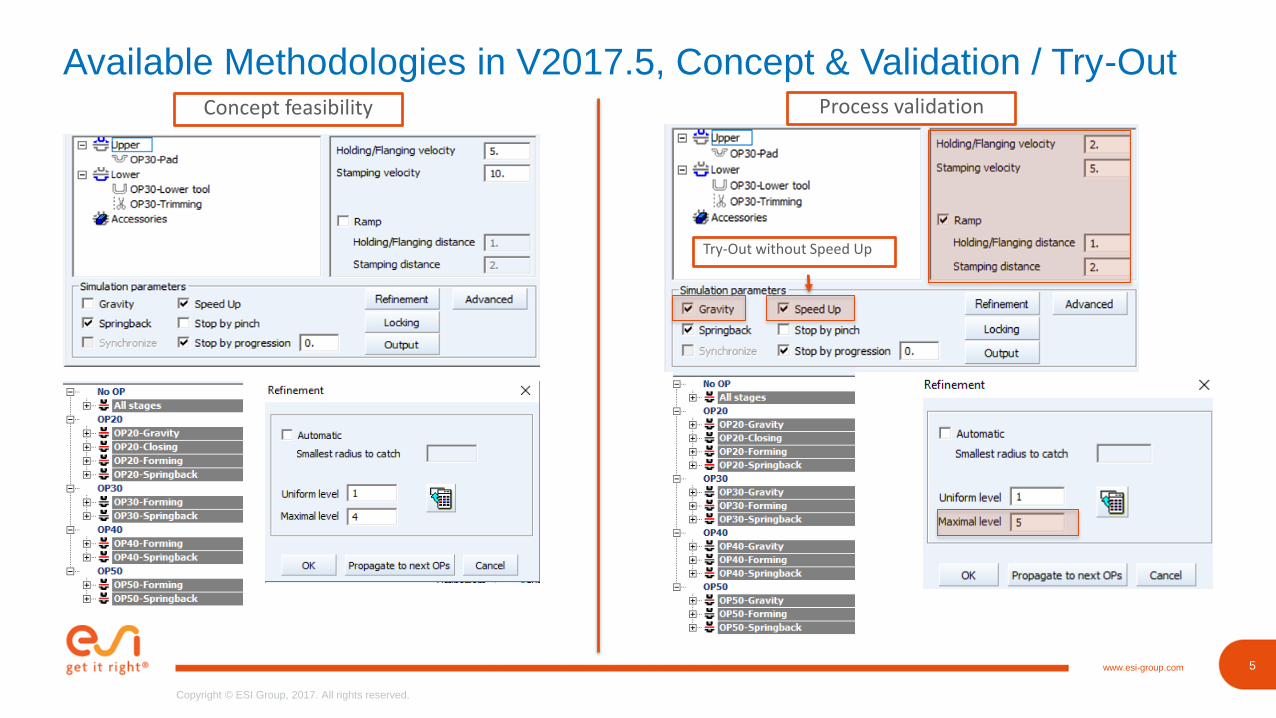
Available Methodologies in V2017.5, Concept & Validation / Try-OutConcept feasibility Process validation
Try-Out without Speed Up
6www.esi-group.com
Copyright © ESI Group, 2017. All rights reserved.
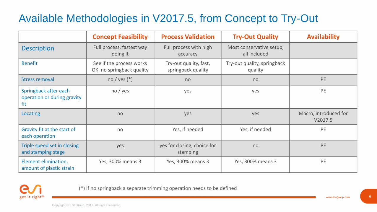
Available Methodologies in V2017.5, from Concept to Try-Out
Concept Feasibility Process Validation Try-Out Quality Availability
Description Full process, fastest way doing it
Full process with highaccuracy
Most conservative setup, all included
Benefit See if the process works OK, no springback quality
Try-out quality, fast, springback quality
Try-out quality, springback quality
Stress removal no / yes (*) no no PE
Springback after each operation or during gravity fit
no / yes yes yes PE
Locating no yes yes Macro, introduced for V2017.5
Gravity fit at the start of each operation
no Yes, if needed Yes, if needed PE
Triple speed set in closingand stamping stage
yes yes for closing, choice for stamping
no PE
Element elimination,amount of plastic strain
Yes, 300% means 3 Yes, 300% means 3 Yes, 300% means 3 PE
(*) If no springback a separate trimming operation needs to be defined
7www.esi-group.com
Copyright © ESI Group, 2017. All rights reserved.
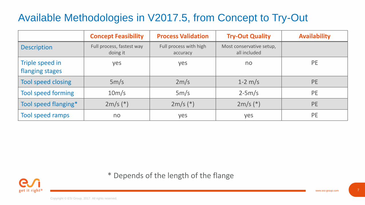
Available Methodologies in V2017.5, from Concept to Try-Out
Concept Feasibility Process Validation Try-Out Quality Availability
Description Full process, fastest way doing it
Full process with highaccuracy
Most conservative setup, all included
Triple speed in flanging stages
yes yes no PE
Tool speed closing 5m/s 2m/s 1-2 m/s PE
Tool speed forming 10m/s 5m/s 2-5m/s PE
Tool speed flanging* 2m/s (*) 2m/s (*) 2m/s (*) PE
Tool speed ramps no yes yes PE
* Depends of the length of the flange
8www.esi-group.com
Copyright © ESI Group, 2017. All rights reserved.
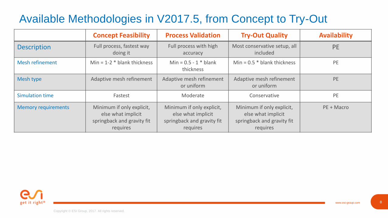
Available Methodologies in V2017.5, from Concept to Try-Out
Concept Feasibility Process Validation Try-Out Quality Availability
Description Full process, fastest way doing it
Full process with highaccuracy
Most conservative setup, all included
PE
Mesh refinement Min = 1-2 * blank thickness Min = 0.5 - 1 * blank thickness
Min = 0.5 * blank thickness PE
Mesh type Adaptive mesh refinement Adaptive mesh refinement or uniform
Adaptive mesh refinement or uniform
PE
Simulation time Fastest Moderate Conservative PE
Memory requirements Minimum if only explicit, else what implicit
springback and gravity fit requires
Minimum if only explicit, else what implicit
springback and gravity fit requires
Minimum if only explicit, else what implicit
springback and gravity fit requires
PE + Macro
9www.esi-group.com
Copyright © ESI Group, 2017. All rights reserved.
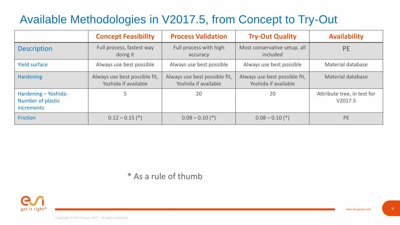
Available Methodologies in V2017.5, from Concept to Try-Out
Concept Feasibility Process Validation Try-Out Quality Availability
Description Full process, fastest way doing it
Full process with highaccuracy
Most conservative setup, all included
PE
Yield surface Always use best possible Always use best possible Always use best possible Material database
Hardening Always use best possible fit, Yoshida if available
Always use best possible fit, Yoshida if available
Always use best possible fit, Yoshida if available
Material database
Hardening – Yoshida: Number of plastic increments
5 20 20 Attribute tree, in test for V2017.5
Friction 0.12 – 0.15 (*) 0.08 – 0.10 (*) 0.08 – 0.10 (*) PE
* As a rule of thumb

10www.esi-group.com
Copyright © ESI Group, 2017. All rights reserved.
10
Copyright © ESI Group, 2017. All rights reserved.
www.esi-group.com
Reduce Try-Out Costs with Accurate Results
PAM-STAMP
Release July 2017
11www.esi-group.com
Copyright © ESI Group, 2017. All rights reserved.
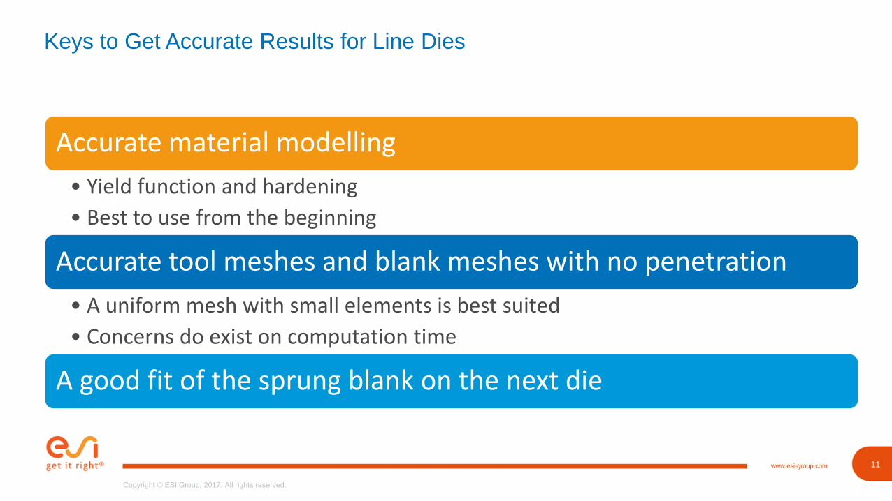
Keys to Get Accurate Results for Line Dies
Accurate material modelling
• Yield function and hardening
• Best to use from the beginning
Accurate tool meshes and blank meshes with no penetration
• A uniform mesh with small elements is best suited
• Concerns do exist on computation time
A good fit of the sprung blank on the next die
14www.esi-group.com
Copyright © ESI Group, 2017. All rights reserved.
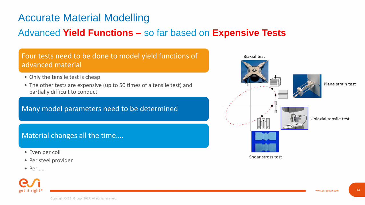
Accurate Material Modelling
Advanced Yield Functions – so far based on Expensive Tests
Four tests need to be done to model yield functions of advanced material
• Only the tensile test is cheap
• The other tests are expensive (up to 50 times of a tensile test) and partially difficult to conduct
Many model parameters need to be determined
Material changes all the time….
• Even per coil
• Per steel provider
• Per……
15www.esi-group.com
Copyright © ESI Group, 2017. All rights reserved.
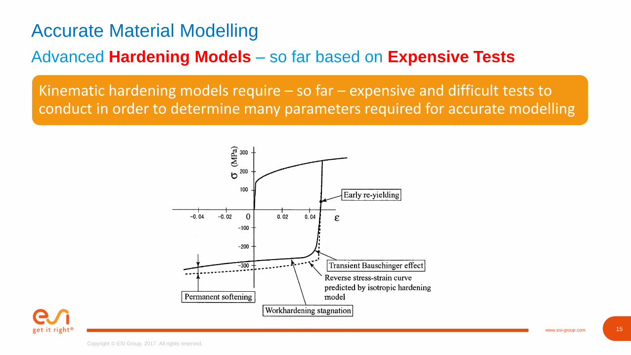
Accurate Material Modelling
Advanced Hardening Models – so far based on Expensive Tests
Kinematic hardening models require – so far – expensive and difficult tests to conduct in order to determine many parameters required for accurate modelling
16www.esi-group.com
Copyright © ESI Group, 2017. All rights reserved.
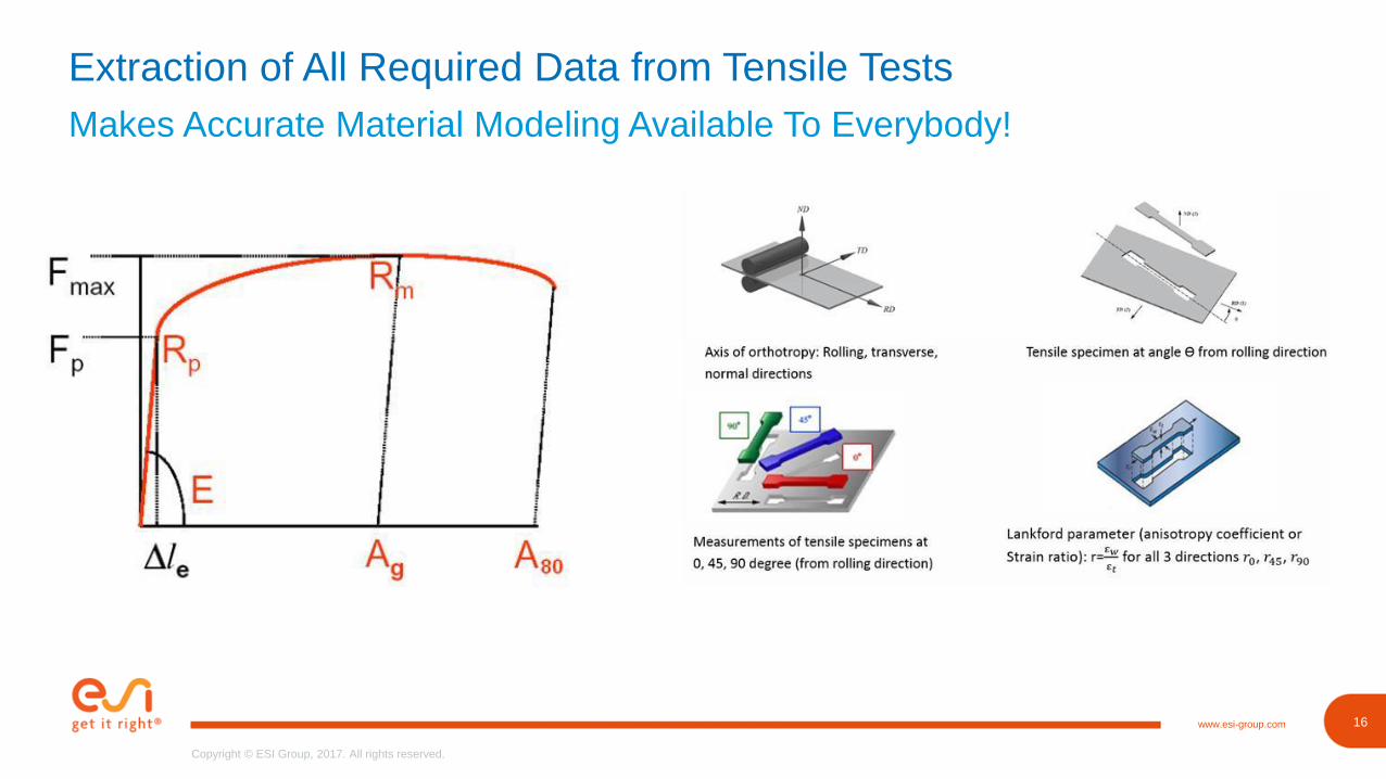
Extraction of All Required Data from Tensile Tests
Makes Accurate Material Modeling Available To Everybody!
17www.esi-group.com
Copyright © ESI Group, 2017. All rights reserved.
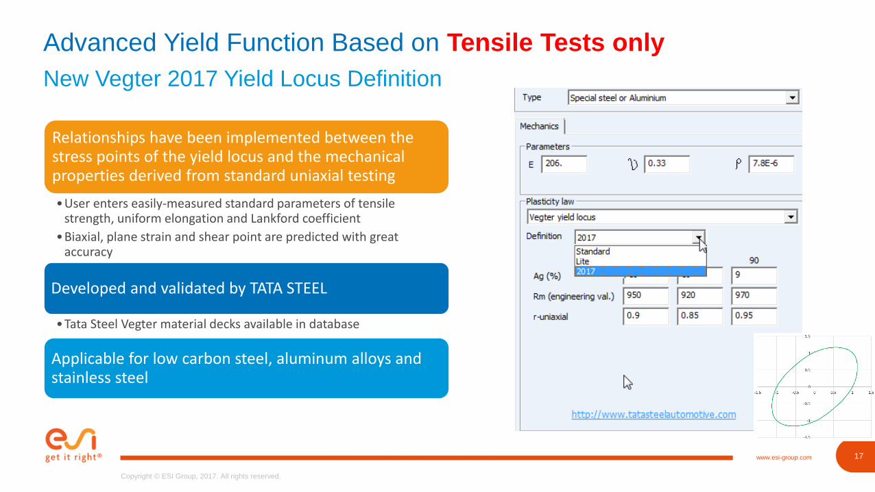
Advanced Yield Function Based on Tensile Tests only
New Vegter 2017 Yield Locus Definition
Relationships have been implemented between the stress points of the yield locus and the mechanical properties derived from standard uniaxial testing
•User enters easily-measured standard parameters of tensile strength, uniform elongation and Lankford coefficient
•Biaxial, plane strain and shear point are predicted with great accuracy
Developed and validated by TATA STEEL
•Tata Steel Vegter material decks available in database
Applicable for low carbon steel, aluminum alloys and stainless steel
18www.esi-group.com
Copyright © ESI Group, 2017. All rights reserved.
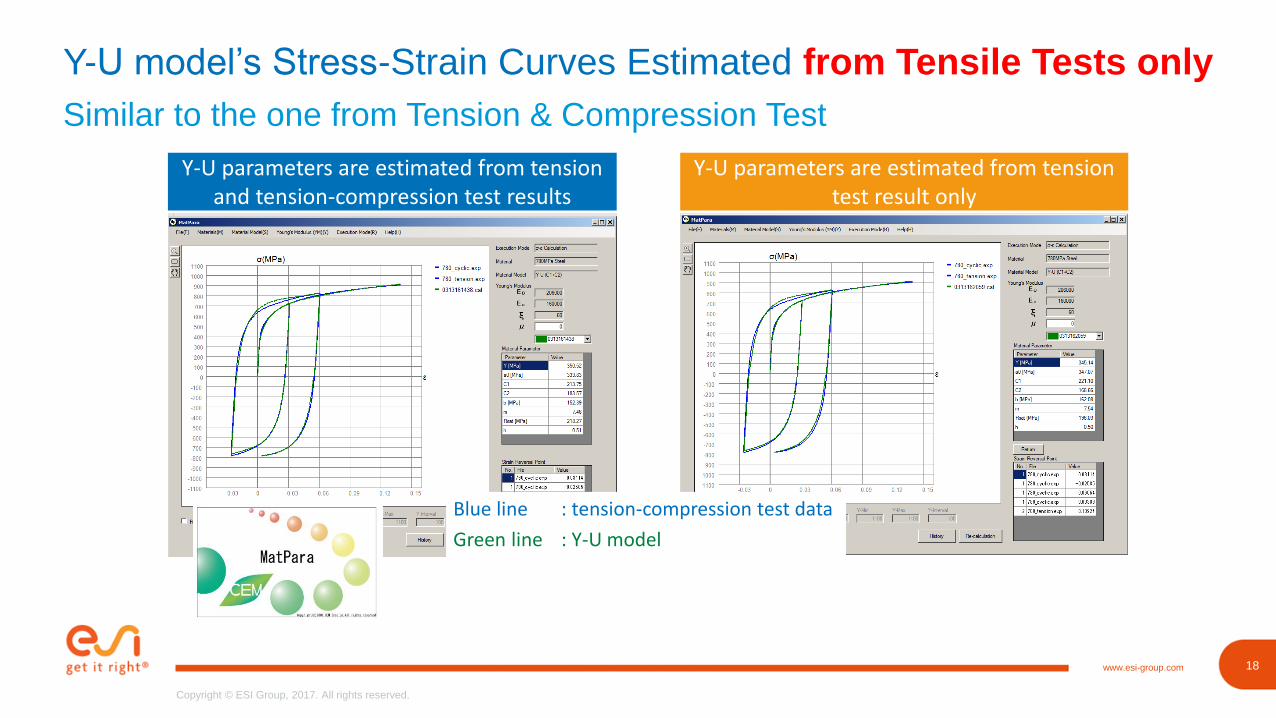
Y-U model’s Stress-Strain Curves Estimated from Tensile Tests only
Similar to the one from Tension & Compression Test
Y-U parameters are estimated from tension and tension-compression test results
Y-U parameters are estimated from tension test result only
Blue line : tension-compression test data
Green line : Y-U model
21www.esi-group.com
Copyright © ESI Group, 2017. All rights reserved.
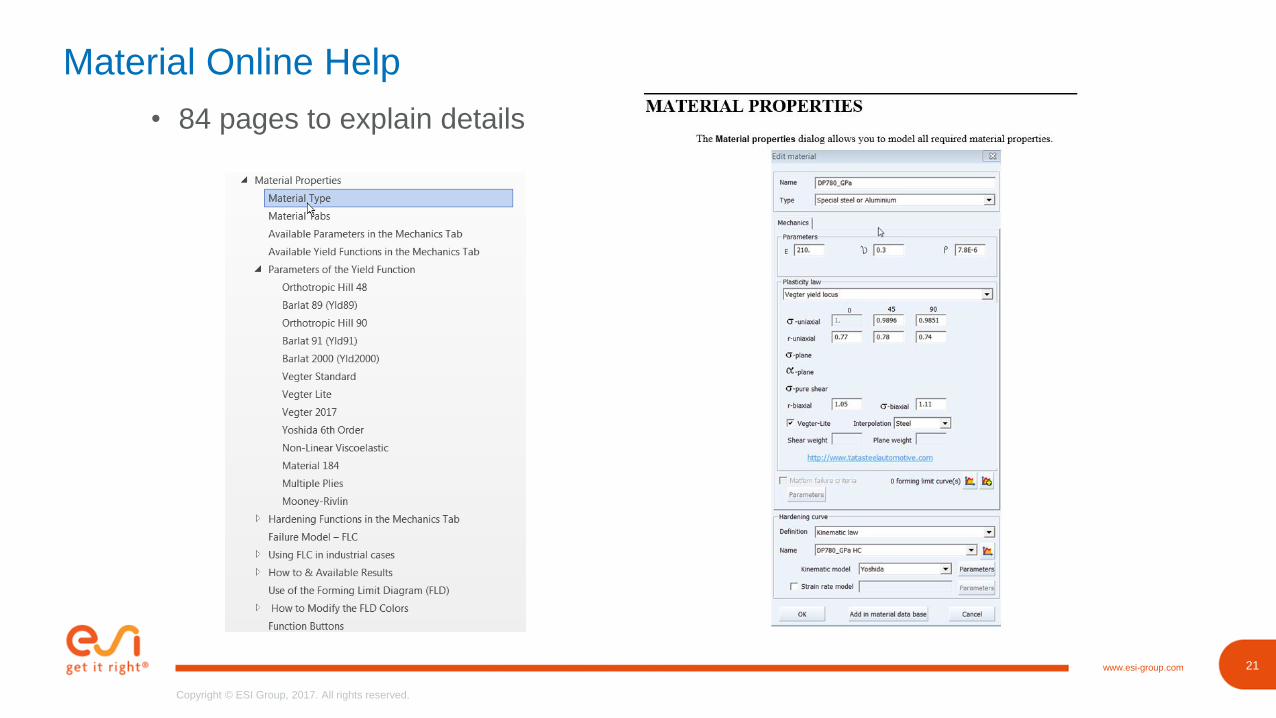
Material Online Help
• 84 pages to explain details
23www.esi-group.com
Copyright © ESI Group, 2017. All rights reserved.
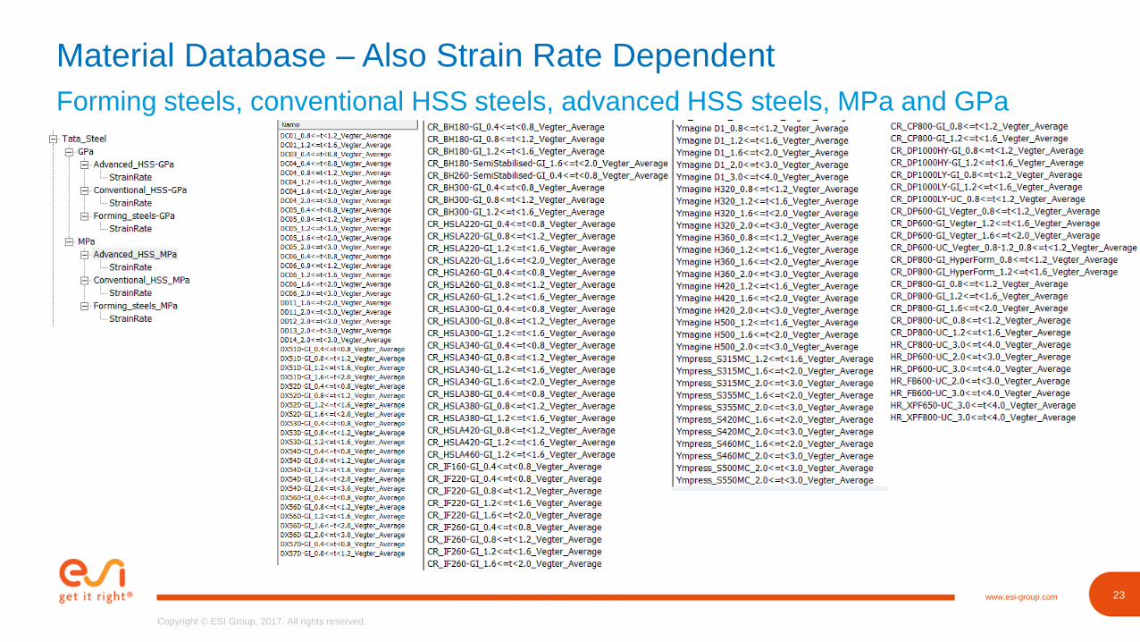
Material Database – Also Strain Rate Dependent
Forming steels, conventional HSS steels, advanced HSS steels, MPa and GPa
24www.esi-group.com
Copyright © ESI Group, 2017. All rights reserved.
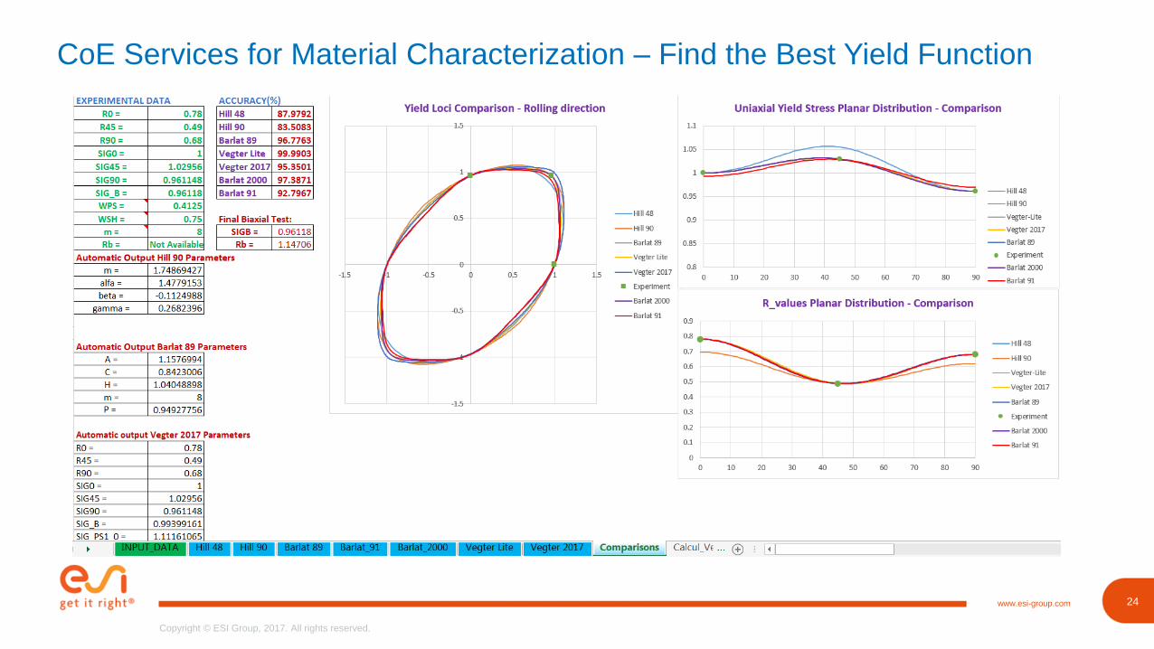
CoE Services for Material Characterization – Find the Best Yield Function
25www.esi-group.com
Copyright © ESI Group, 2017. All rights reserved.
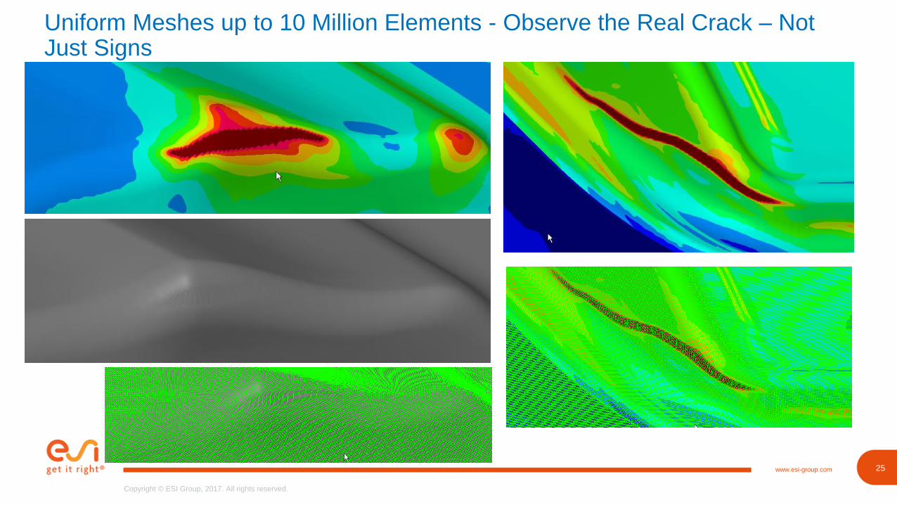
Uniform Meshes up to 10 Million Elements - Observe the Real Crack – Not Just Signs
26www.esi-group.com
Copyright © ESI Group, 2017. All rights reserved.
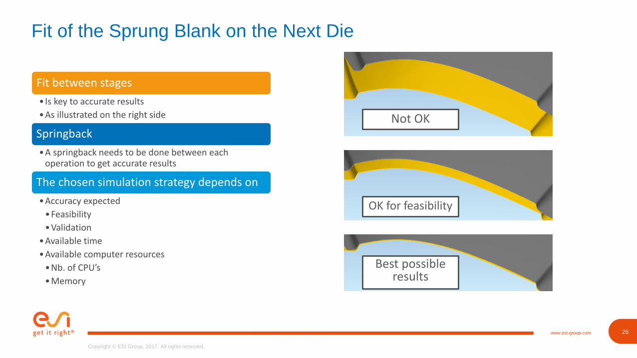
Fit of the Sprung Blank on the Next Die
Fit between stages
• Is key to accurate results
•As illustrated on the right side
Springback
•A springback needs to be done between each operation to get accurate results
The chosen simulation strategy depends on
•Accuracy expected
•Feasibility
•Validation
•Available time
•Available computer resources
•Nb. of CPU’s
•Memory
Not OK
OK for feasibility
Best possible results
27www.esi-group.com
Copyright © ESI Group, 2017. All rights reserved.
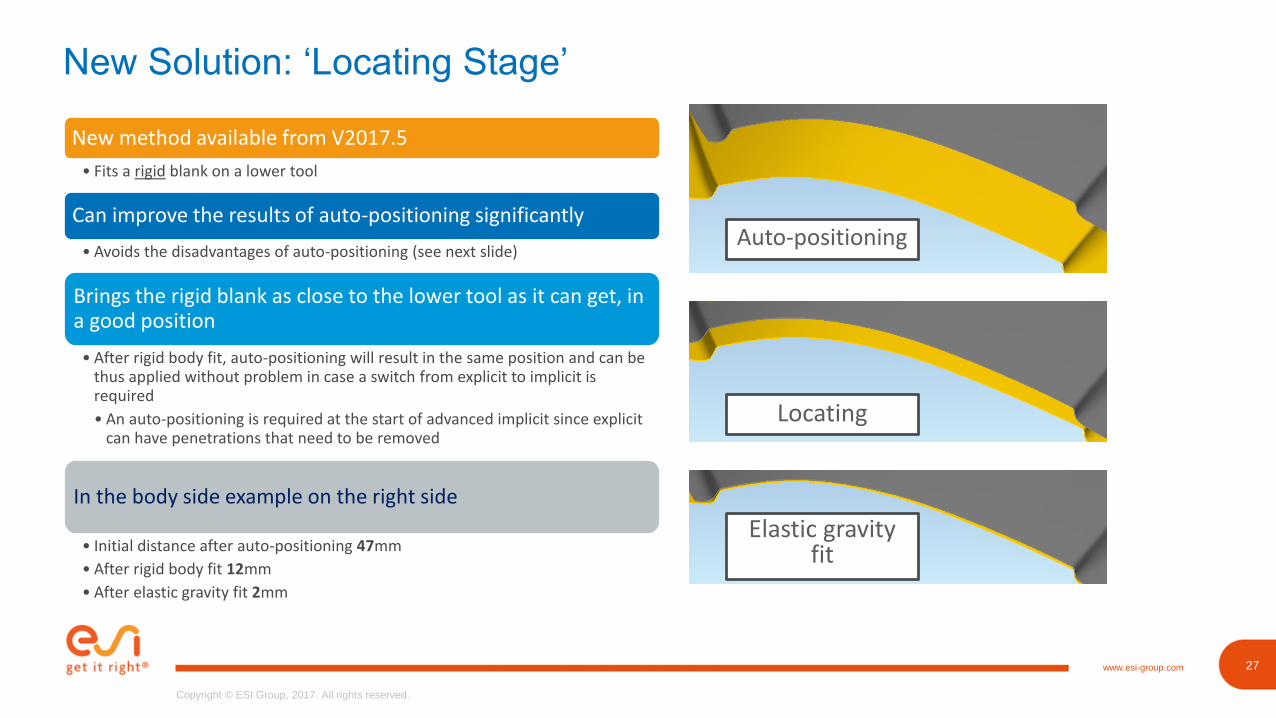
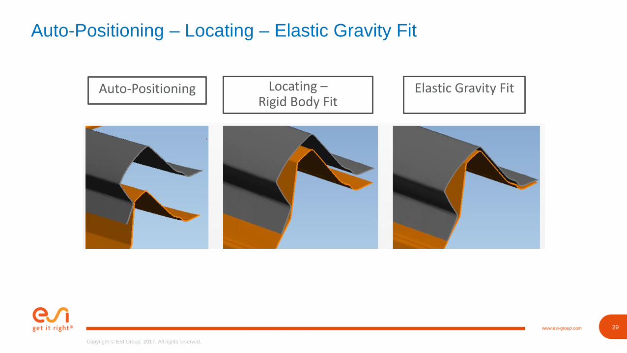
New Solution: ‘Locating Stage’
New method available from V2017.5
• Fits a rigid blank on a lower tool
Can improve the results of auto-positioning significantly
• Avoids the disadvantages of auto-positioning (see next slide)
Brings the rigid blank as close to the lower tool as it can get, in a good position
• After rigid body fit, auto-positioning will result in the same position and can be thus applied without problem in case a switch from explicit to implicit is required
• An auto-positioning is required at the start of advanced implicit since explicit can have penetrations that need to be removed
In the body side example on the right side
• Initial distance after auto-positioning 47mm
• After rigid body fit 12mm
• After elastic gravity fit 2mm
Auto-positioning
Locating
Elastic gravity fit
28www.esi-group.com
Copyright © ESI Group, 2017. All rights reserved.
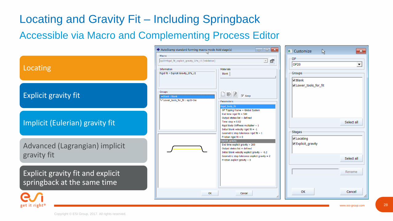
Accessible via Macro and Complementing Process Editor
Locating and Gravity Fit – Including Springback
Locating
Explicit gravity fit
Implicit (Eulerian) gravity fit
Advanced (Lagrangian) implicit gravity fit
Explicit gravity fit and explicit springback at the same time
29www.esi-group.com
Copyright © ESI Group, 2017. All rights reserved.
Auto-Positioning – Locating – Elastic Gravity Fit
Auto-Positioning Locating –Rigid Body Fit
Elastic Gravity Fit

31www.esi-group.com
Copyright © ESI Group, 2017. All rights reserved.
Engineering Problems to Solve with This Capability
Check the Exact Fit between Stages – Also for Progressive Dies
• OP
• Transport and fit
‣ Springback
‣ Locating
‣ Gravity fit – if needed
• Explicit or implicit
• Next OP
• Check if the blank / stripe sits on the next die
• The locating will already show issues with positioning, so it might be good enough
• As the process happens in reality
• No simplification
• Specific recommendation‣ For explicit gravity fit a geometrical
tolerance of 2 is sufficient since a sprung blank in equilibrium is used
Process Benefit
32www.esi-group.com
Copyright © ESI Group, 2017. All rights reserved.
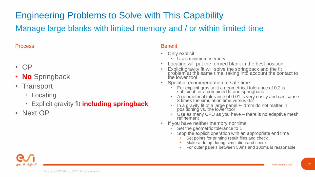
Engineering Problems to Solve with This Capability
Manage large blanks with limited memory and / or within limited time
• OP
• No Springback
• Transport
‣ Locating
‣ Explicit gravity fit including springback
• Next OP
• Only explicit‣ Uses minimum memory
• Locating will put the formed blank in the best position• Explicit gravity fit will solve the springback and the fit
problem at the same time, taking into account the contact to the lower tool
• Specific recommendation to safe time‣ For explicit gravity fit a geometrical tolerance of 0.2 is
sufficient for a combined fit and springback‣ A geometrical tolerance of 0.01 is very costly and can cause
3 times the simulation time versus 0.2‣ In a gravity fit of a large panel +- 1mm do not matter in
positioning vs. the lower tool‣ Use as many CPU as you have – there is no adaptive mesh
refinement• If you have neither memory nor time
‣ Set the geometric tolerance to 1‣ Stop the explicit operation with an appropriate end time
• Set points for printing result files and check• Make a dump during simulation and check• For outer panels between 50ms and 100ms is reasonable
Process Benefit
38www.esi-group.com
Copyright © ESI Group, 2017. All rights reserved.
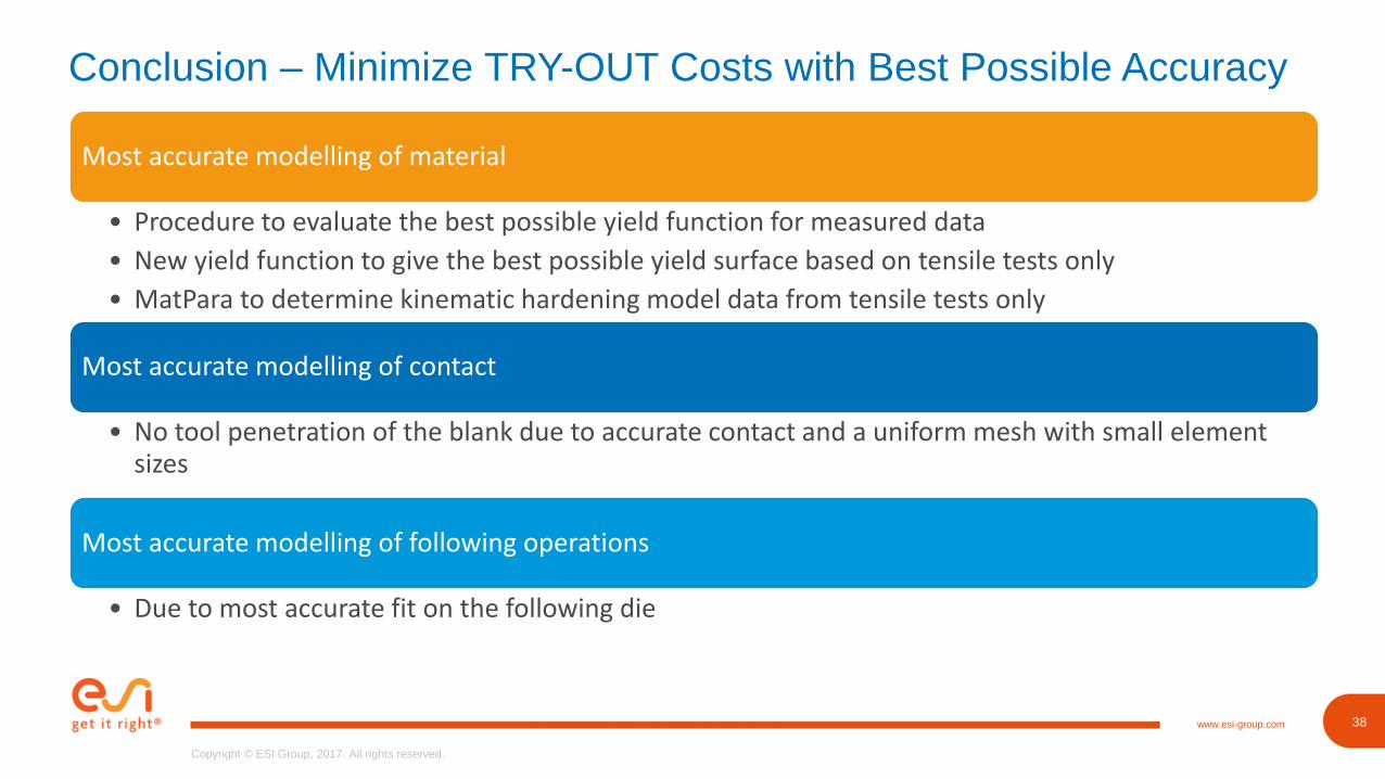
Conclusion – Minimize TRY-OUT Costs with Best Possible Accuracy
Most accurate modelling of material
• Procedure to evaluate the best possible yield function for measured data
• New yield function to give the best possible yield surface based on tensile tests only
• MatPara to determine kinematic hardening model data from tensile tests only
Most accurate modelling of contact
• No tool penetration of the blank due to accurate contact and a uniform mesh with small element sizes
Most accurate modelling of following operations
• Due to most accurate fit on the following die
39www.esi-group.com
Copyright © ESI Group, 2017. All rights reserved.
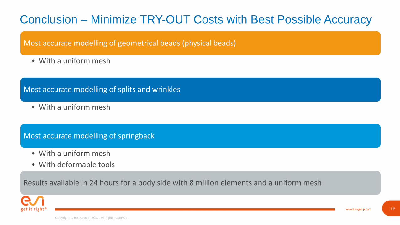
Conclusion – Minimize TRY-OUT Costs with Best Possible Accuracy
Most accurate modelling of geometrical beads (physical beads)
• With a uniform mesh
Most accurate modelling of splits and wrinkles
• With a uniform mesh
Most accurate modelling of springback
• With a uniform mesh
• With deformable tools
Results available in 24 hours for a body side with 8 million elements and a uniform mesh
40www.esi-group.com
Copyright © ESI Group, 2017. All rights reserved.
40
Copyright © ESI Group, 2017. All rights reserved.
www.esi-group.com
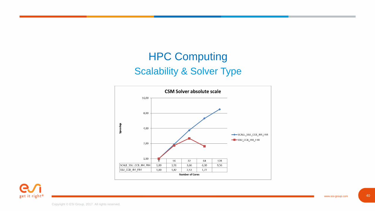
HPC Computing
Scalability & Solver Type
41www.esi-group.com
Copyright © ESI Group, 2017. All rights reserved.
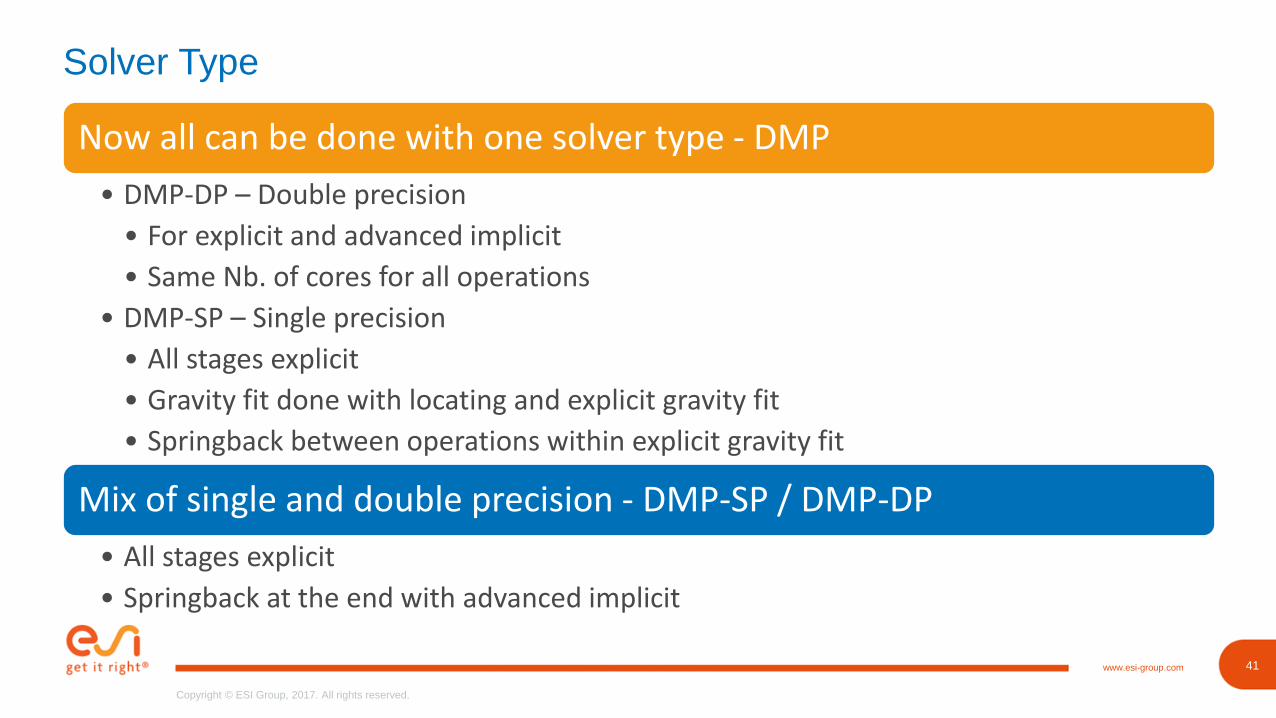
Solver Type
Now all can be done with one solver type - DMP
• DMP-DP – Double precision
• For explicit and advanced implicit
• Same Nb. of cores for all operations
• DMP-SP – Single precision
• All stages explicit
• Gravity fit done with locating and explicit gravity fit
• Springback between operations within explicit gravity fit
Mix of single and double precision - DMP-SP / DMP-DP
• All stages explicit
• Springback at the end with advanced implicit
43www.esi-group.com
Copyright © ESI Group, 2017. All rights reserved.
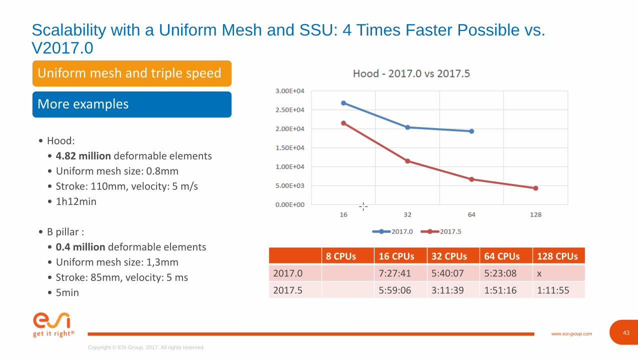
Scalability with a Uniform Mesh and SSU: 4 Times Faster Possible vs. V2017.0
Uniform mesh and triple speed
More examples
• Hood:
• 4.82 million deformable elements
• Uniform mesh size: 0.8mm
• Stroke: 110mm, velocity: 5 m/s
• 1h12min
• B pillar :
• 0.4 million deformable elements
• Uniform mesh size: 1,3mm
• Stroke: 85mm, velocity: 5 ms
• 5min
8 CPUs 16 CPUs 32 CPUs 64 CPUs 128 CPUs
2017.0 7:27:41 5:40:07 5:23:08 x
2017.5 5:59:06 3:11:39 1:51:16 1:11:55
44www.esi-group.com
Copyright © ESI Group, 2017. All rights reserved.
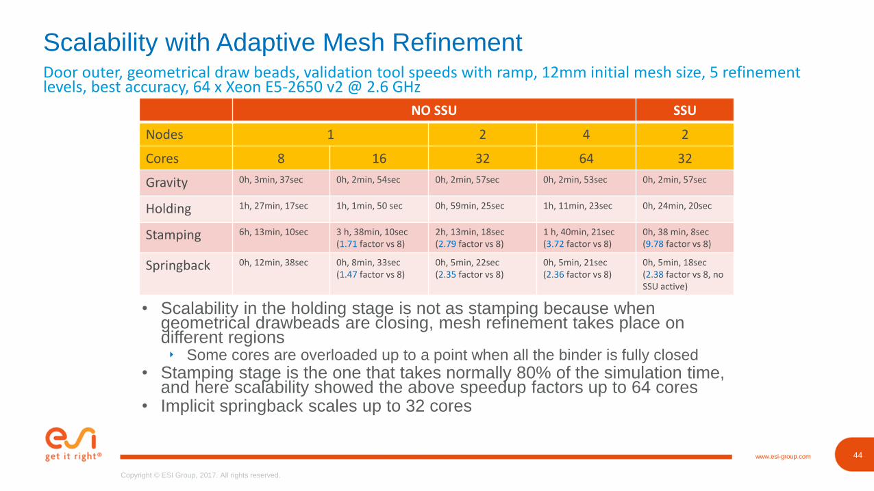
Door outer, geometrical draw beads, validation tool speeds with ramp, 12mm initial mesh size, 5 refinement levels, best accuracy, 64 x Xeon E5-2650 v2 @ 2.6 GHz
Scalability with Adaptive Mesh Refinement
NO SSU SSU
Nodes 1 2 4 2
Cores 8 16 32 64 32
Gravity 0h, 3min, 37sec 0h, 2min, 54sec 0h, 2min, 57sec 0h, 2min, 53sec 0h, 2min, 57sec
Holding 1h, 27min, 17sec 1h, 1min, 50 sec 0h, 59min, 25sec 1h, 11min, 23sec 0h, 24min, 20sec
Stamping 6h, 13min, 10sec 3 h, 38min, 10sec(1.71 factor vs 8)
2h, 13min, 18sec(2.79 factor vs 8)
1 h, 40min, 21sec(3.72 factor vs 8)
0h, 38 min, 8sec(9.78 factor vs 8)
Springback 0h, 12min, 38sec 0h, 8min, 33sec(1.47 factor vs 8)
0h, 5min, 22sec(2.35 factor vs 8)
0h, 5min, 21sec(2.36 factor vs 8)
0h, 5min, 18sec(2.38 factor vs 8, no SSU active)
• Scalability in the holding stage is not as stamping because when geometrical drawbeads are closing, mesh refinement takes place on different regions‣ Some cores are overloaded up to a point when all the binder is fully closed
• Stamping stage is the one that takes normally 80% of the simulation time, and here scalability showed the above speedup factors up to 64 cores
• Implicit springback scales up to 32 cores
46www.esi-group.com
Copyright © ESI Group, 2017. All rights reserved.
46
Copyright © ESI Group, 2017. All rights reserved.
www.esi-group.com
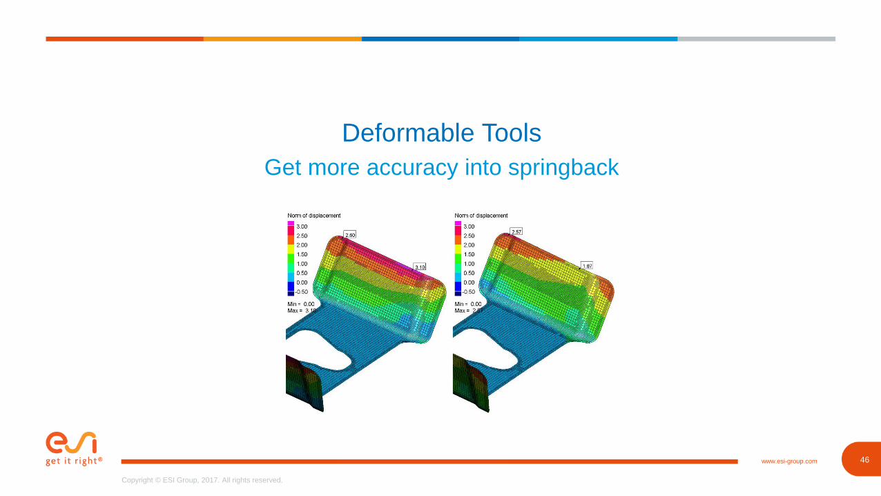
Deformable Tools
Get more accuracy into springback
47www.esi-group.com
Copyright © ESI Group, 2017. All rights reserved.
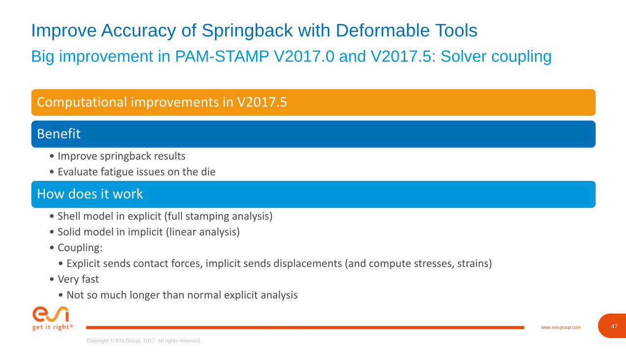
Big improvement in PAM-STAMP V2017.0 and V2017.5: Solver coupling
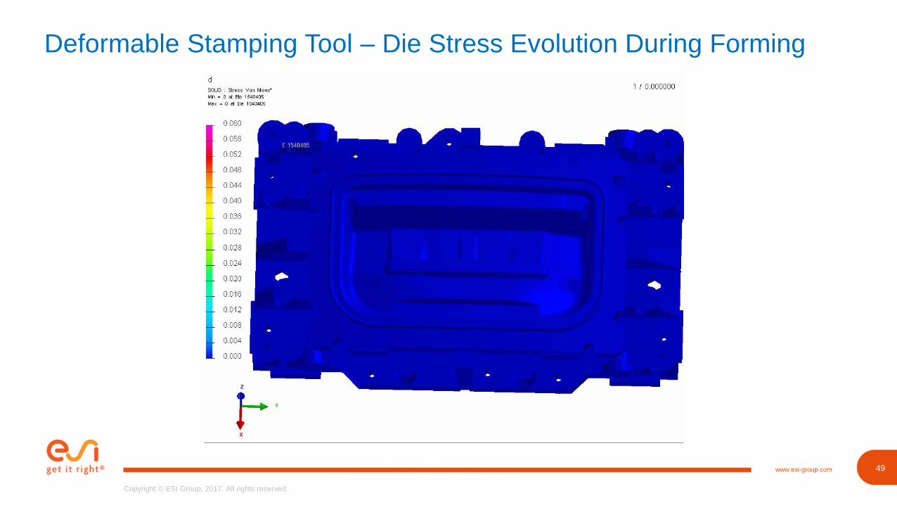
Improve Accuracy of Springback with Deformable Tools
Computational improvements in V2017.5
Benefit
• Improve springback results
• Evaluate fatigue issues on the die
How does it work
• Shell model in explicit (full stamping analysis)
• Solid model in implicit (linear analysis)
• Coupling:
• Explicit sends contact forces, implicit sends displacements (and compute stresses, strains)
• Very fast
• Not so much longer than normal explicit analysis
48www.esi-group.com
Copyright © ESI Group, 2017. All rights reserved.
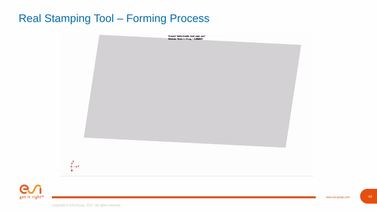
Real Stamping Tool – Forming Process
49www.esi-group.com
Copyright © ESI Group, 2017. All rights reserved.
Deformable Stamping Tool – Die Stress Evolution During Forming
50www.esi-group.com
Copyright © ESI Group, 2017. All rights reserved.
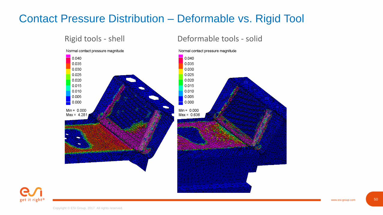
Contact Pressure Distribution – Deformable vs. Rigid Tool
Rigid tools - shell Deformable tools - solid
51www.esi-group.com
Copyright © ESI Group, 2017. All rights reserved.
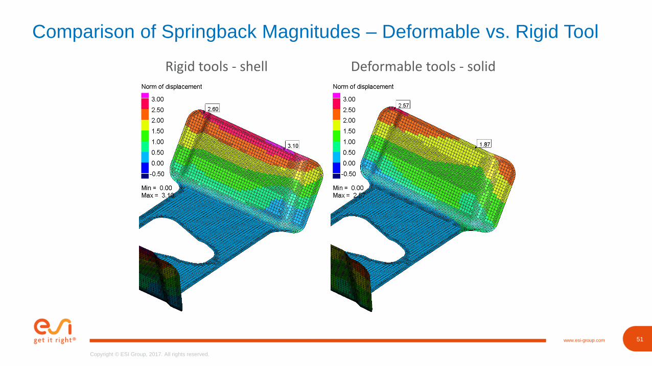
Comparison of Springback Magnitudes – Deformable vs. Rigid Tool
Rigid tools - shell Deformable tools - solid
52www.esi-group.com
Copyright © ESI Group, 2017. All rights reserved.
52
Copyright © ESI Group, 2017. All rights reserved.
www.esi-group.com
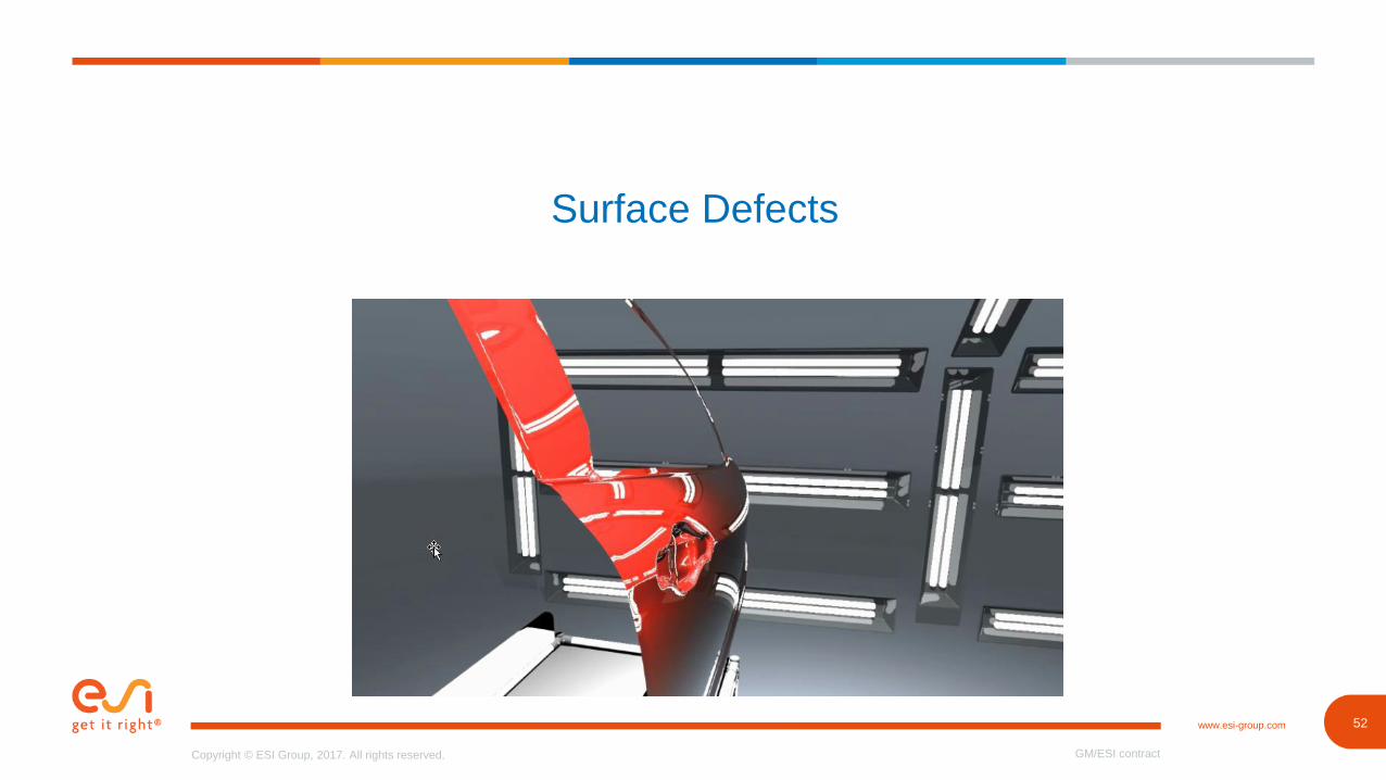
Surface Defects
GM/ESI contract
53www.esi-group.com
Copyright © ESI Group, 2017. All rights reserved.
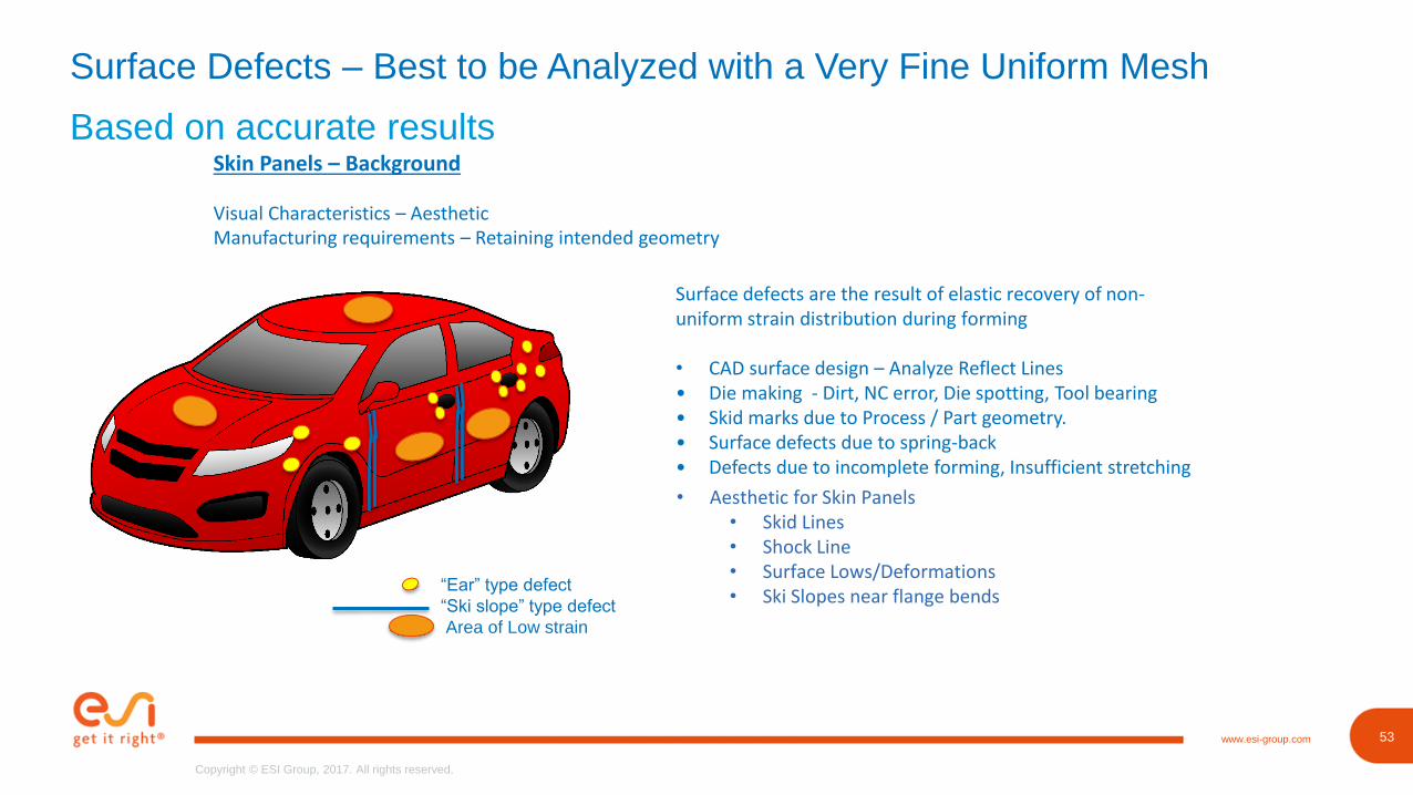
Surface Defects – Best to be Analyzed with a Very Fine Uniform Mesh
Based on accurate resultsSkin Panels – Background
Visual Characteristics – AestheticManufacturing requirements – Retaining intended geometry
“Ear” type defect
“Ski slope” type defect
Area of Low strain
Surface defects are the result of elastic recovery of non-uniform strain distribution during forming
• CAD surface design – Analyze Reflect Lines • Die making - Dirt, NC error, Die spotting, Tool bearing• Skid marks due to Process / Part geometry. • Surface defects due to spring-back• Defects due to incomplete forming, Insufficient stretching
• Aesthetic for Skin Panels • Skid Lines• Shock Line • Surface Lows/Deformations • Ski Slopes near flange bends
54www.esi-group.com
Copyright © ESI Group, 2017. All rights reserved.
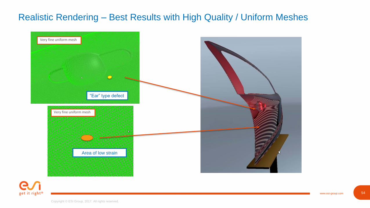
Realistic Rendering – Best Results with High Quality / Uniform Meshes
Area of low strain
“Ear” type defect
Very fine uniform mesh
Very fine uniform mesh
55www.esi-group.com
Copyright © ESI Group, 2017. All rights reserved.
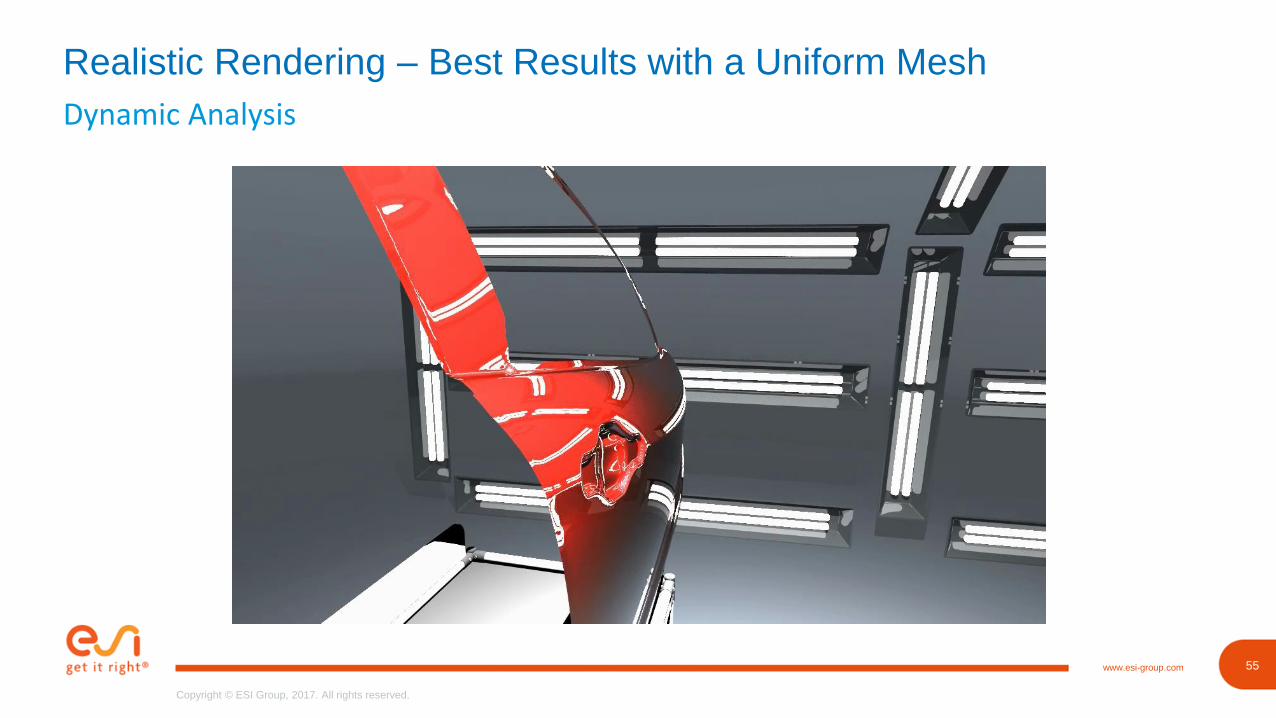
Dynamic Analysis
Realistic Rendering – Best Results with a Uniform Mesh
56www.esi-group.com
Copyright © ESI Group, 2017. All rights reserved.
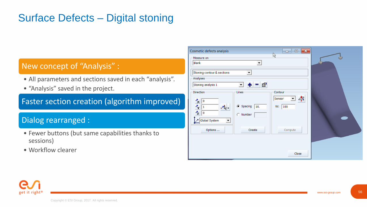
Surface Defects – Digital stoning
New concept of “Analysis” :
• All parameters and sections saved in each “analysis”.
• “Analysis” saved in the project.
Faster section creation (algorithm improved)
Dialog rearranged :
• Fewer buttons (but same capabilities thanks to sessions)
• Workflow clearer
57www.esi-group.com
Copyright © ESI Group, 2017. All rights reserved.
57
Copyright © ESI Group, 2017. All rights reserved.
www.esi-group.com
Robustness
GM/ESI contract
58www.esi-group.com
Copyright © ESI Group, 2017. All rights reserved.
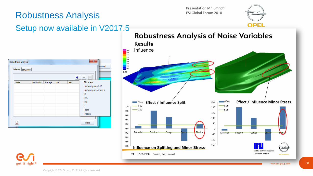
Presentation Mr. Emrich ESI Global Forum 2010Robustness Analysis
Setup now available in V2017.5
59www.esi-group.com
Copyright © ESI Group, 2017. All rights reserved.
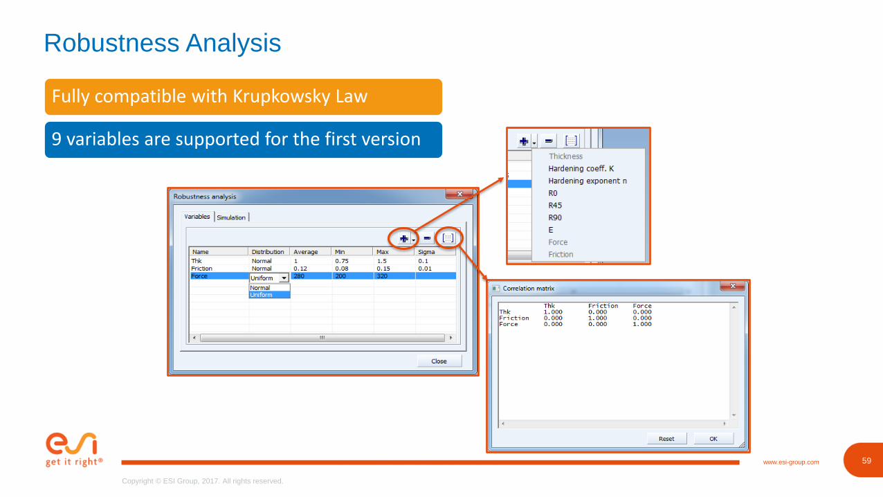
Robustness Analysis
Fully compatible with Krupkowsky Law
9 variables are supported for the first version
61www.esi-group.com
Copyright © ESI Group, 2017. All rights reserved.
61
Copyright © ESI Group, 2017. All rights reserved.
www.esi-group.com
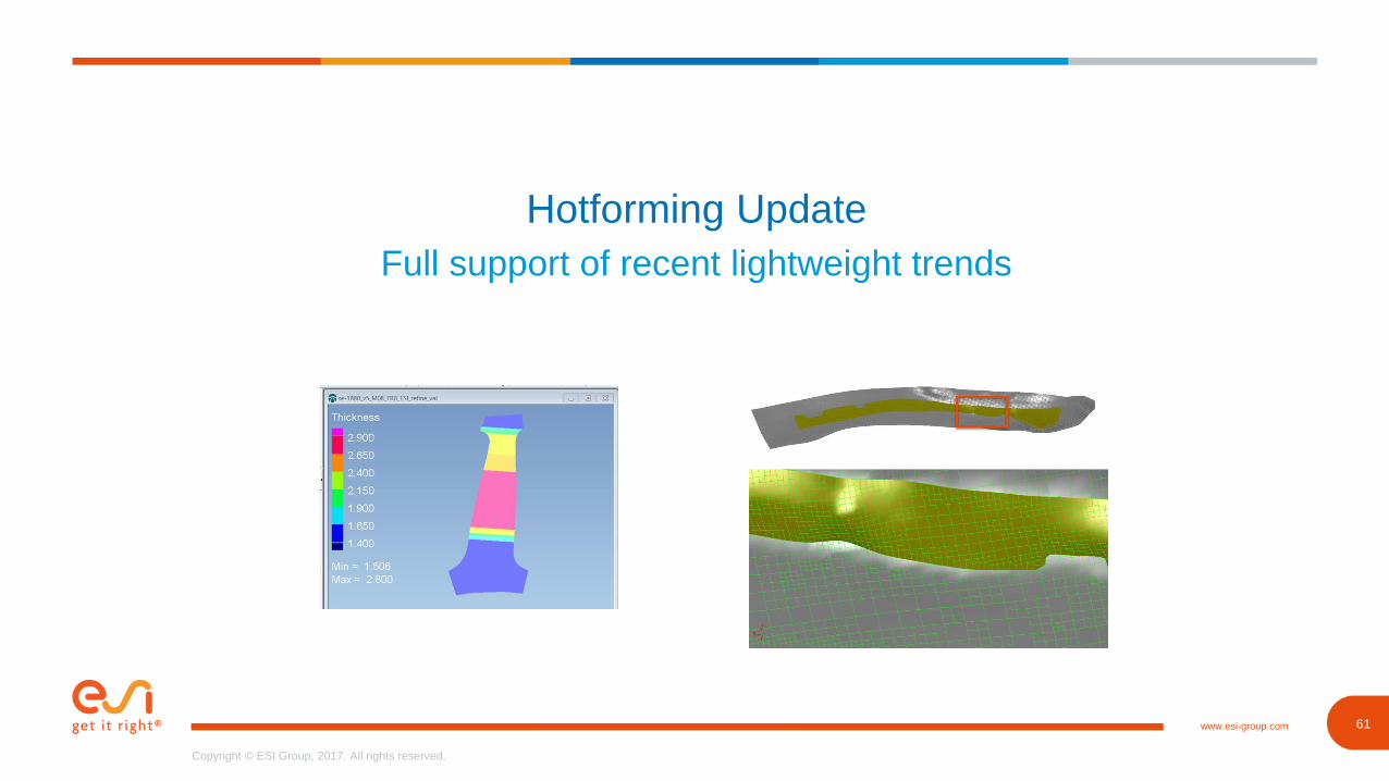
Hotforming Update
Full support of recent lightweight trends
62www.esi-group.com
Copyright © ESI Group, 2017. All rights reserved.
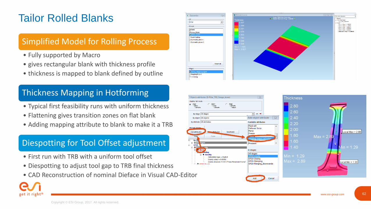
Tailor Rolled Blanks
Simplified Model for Rolling Process
• Fully supported by Macro
• gives rectangular blank with thickness profile
• thickness is mapped to blank defined by outline
Thickness Mapping in Hotforming
Diespotting for Tool Offset adjustment
• Typical first feasibility runs with uniform thickness
• Flattening gives transition zones on flat blank
• Adding mapping attribute to blank to make it a TRB
• First run with TRB with a uniform tool offset
• Diespotting to adjust tool gap to TRB final thickness
• CAD Reconstruction of nominal Dieface in Visual CAD-Editor
63www.esi-group.com
Copyright © ESI Group, 2017. All rights reserved.
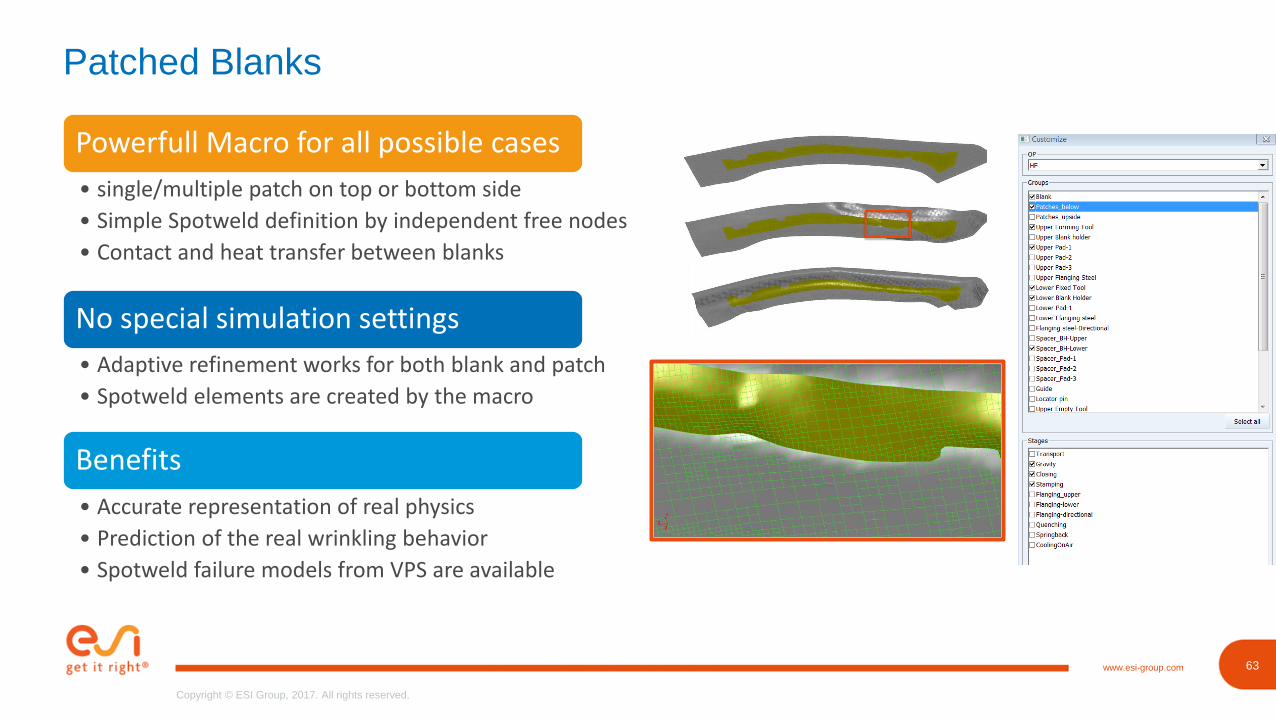
Patched Blanks
Powerfull Macro for all possible cases
• single/multiple patch on top or bottom side
• Simple Spotweld definition by independent free nodes
• Contact and heat transfer between blanks
No special simulation settings
Benefits
• Adaptive refinement works for both blank and patch
• Spotweld elements are created by the macro
• Accurate representation of real physics
• Prediction of the real wrinkling behavior
• Spotweld failure models from VPS are available
64www.esi-group.com
Copyright © ESI Group, 2017. All rights reserved.
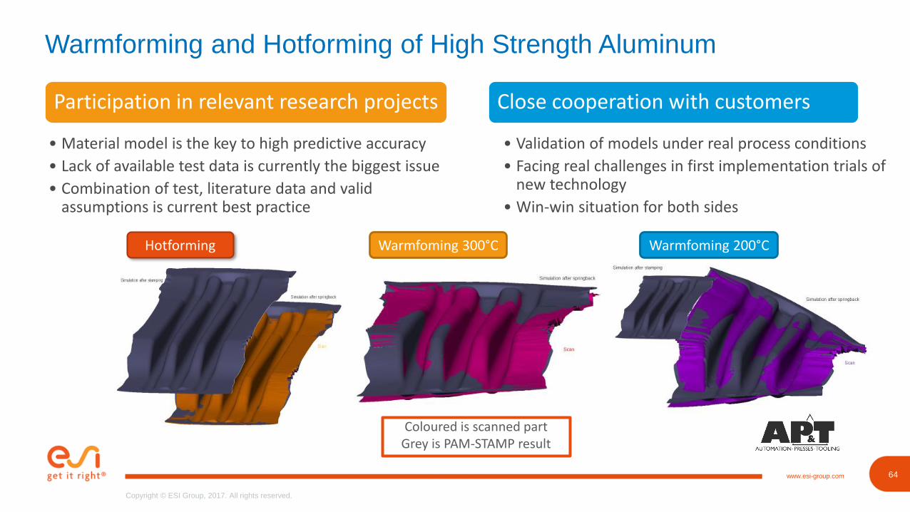
Warmforming and Hotforming of High Strength Aluminum
Participation in relevant research projects
• Material model is the key to high predictive accuracy
• Lack of available test data is currently the biggest issue
• Combination of test, literature data and valid assumptions is current best practice
Hotforming Warmfoming 300°C Warmfoming 200°C
Close cooperation with customers
• Validation of models under real process conditions
• Facing real challenges in first implementation trials of new technology
• Win-win situation for both sides
Coloured is scanned partGrey is PAM-STAMP result
65www.esi-group.com
Copyright © ESI Group, 2017. All rights reserved.
65
Copyright © ESI Group, 2017. All rights reserved.
www.esi-group.com
Efficiency Improvements
GUI
66www.esi-group.com
Copyright © ESI Group, 2017. All rights reserved.
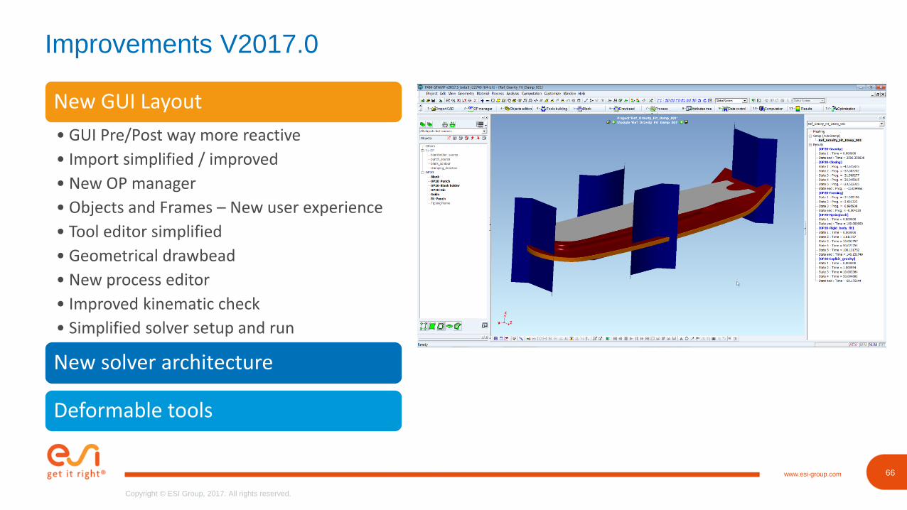
Improvements V2017.0
New GUI Layout
• GUI Pre/Post way more reactive
• Import simplified / improved
• New OP manager
• Objects and Frames – New user experience
• Tool editor simplified
• Geometrical drawbead
• New process editor
• Improved kinematic check
• Simplified solver setup and run
New solver architecture
Deformable tools
67www.esi-group.com
Copyright © ESI Group, 2017. All rights reserved.
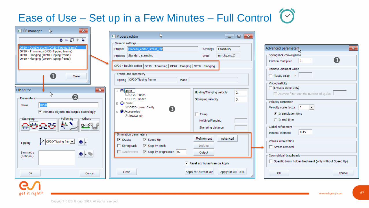
Ease of Use – Set up in a Few Minutes – Full Control
69www.esi-group.com
Copyright © ESI Group, 2017. All rights reserved.
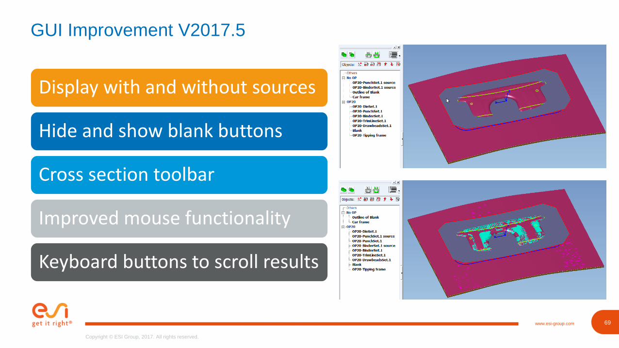
GUI Improvement V2017.5
Display with and without sources
Hide and show blank buttons
Cross section toolbar
Improved mouse functionality
Keyboard buttons to scroll results
70www.esi-group.com
Copyright © ESI Group, 2017. All rights reserved.
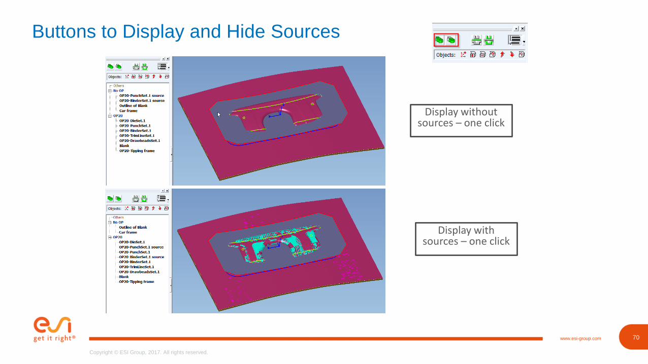
Buttons to Display and Hide Sources
Display without sources – one click
Display with sources – one click
72www.esi-group.com
Copyright © ESI Group, 2017. All rights reserved.
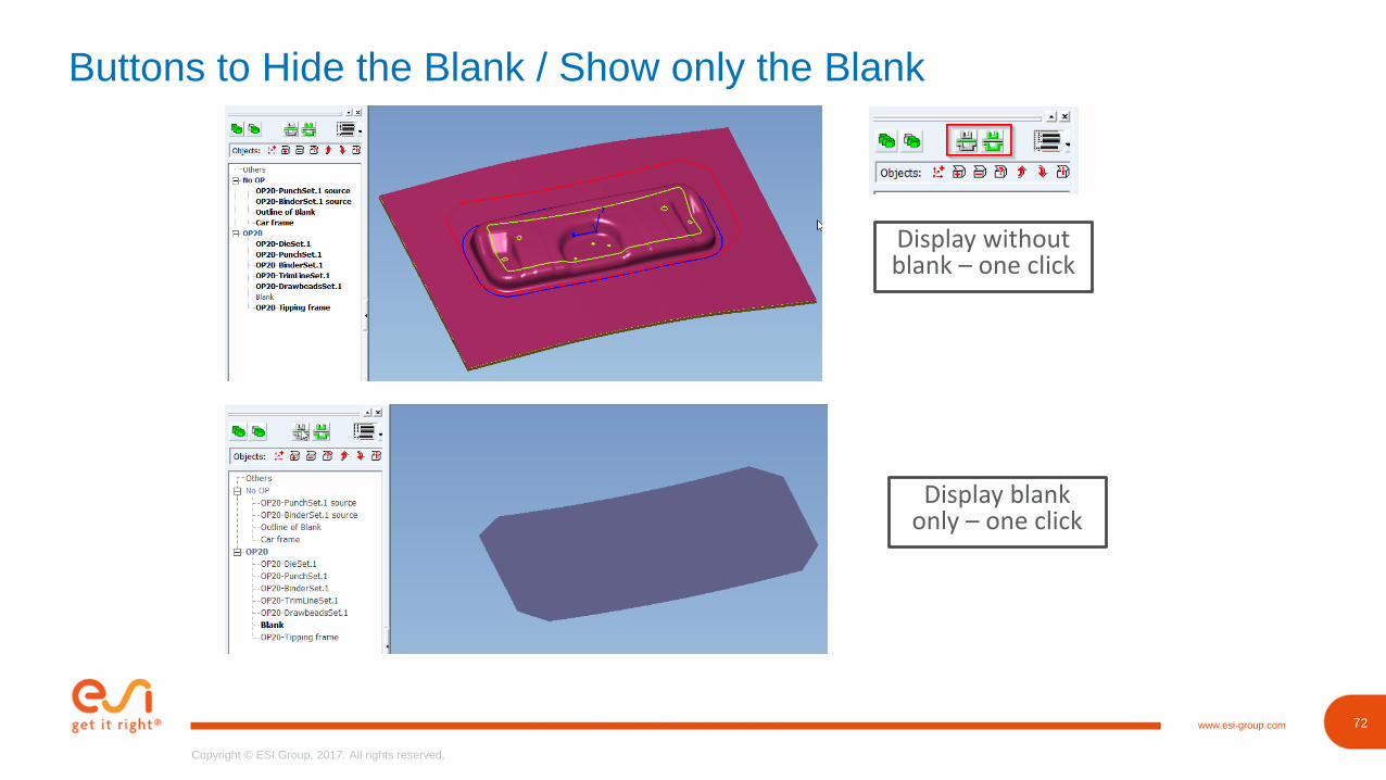
Buttons to Hide the Blank / Show only the Blank
Display without blank – one click
Display blank only – one click
73www.esi-group.com
Copyright © ESI Group, 2017. All rights reserved.
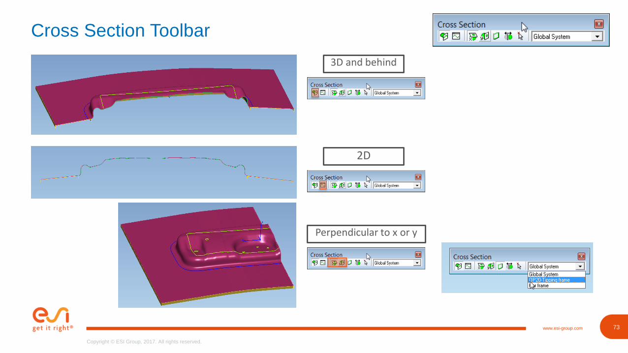
Cross Section Toolbar
3D and behind
2D
Perpendicular to x or y
77www.esi-group.com
Copyright © ESI Group, 2017. All rights reserved.
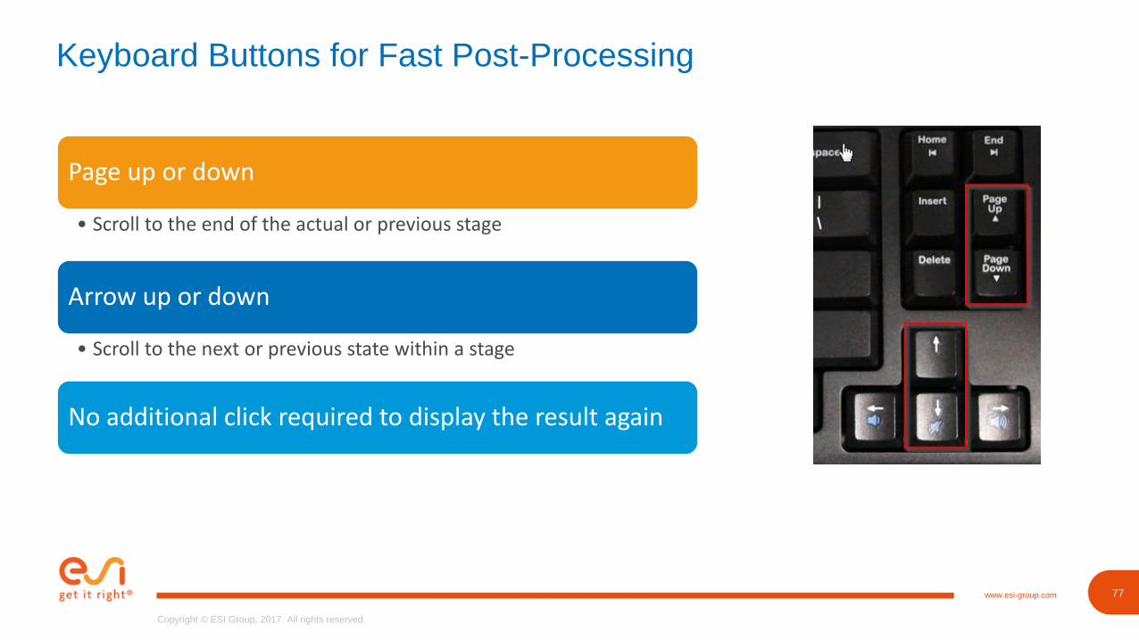
Keyboard Buttons for Fast Post-Processing
Page up or down
• Scroll to the end of the actual or previous stage
Arrow up or down
• Scroll to the next or previous state within a stage
No additional click required to display the result again
78www.esi-group.com
Copyright © ESI Group, 2017. All rights reserved.
78
Copyright © ESI Group, 2017. All rights reserved.
www.esi-group.com
Miscellaneous
Pre-Processing
79www.esi-group.com
Copyright © ESI Group, 2017. All rights reserved.
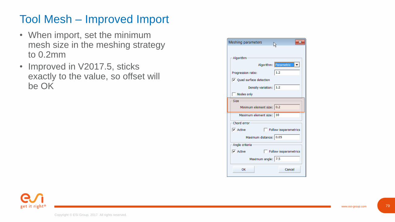
Tool Mesh – Improved Import
• When import, set the minimum mesh size in the meshing strategy to 0.2mm
• Improved in V2017.5, sticks exactly to the value, so offset will be OK
80www.esi-group.com
Copyright © ESI Group, 2017. All rights reserved.
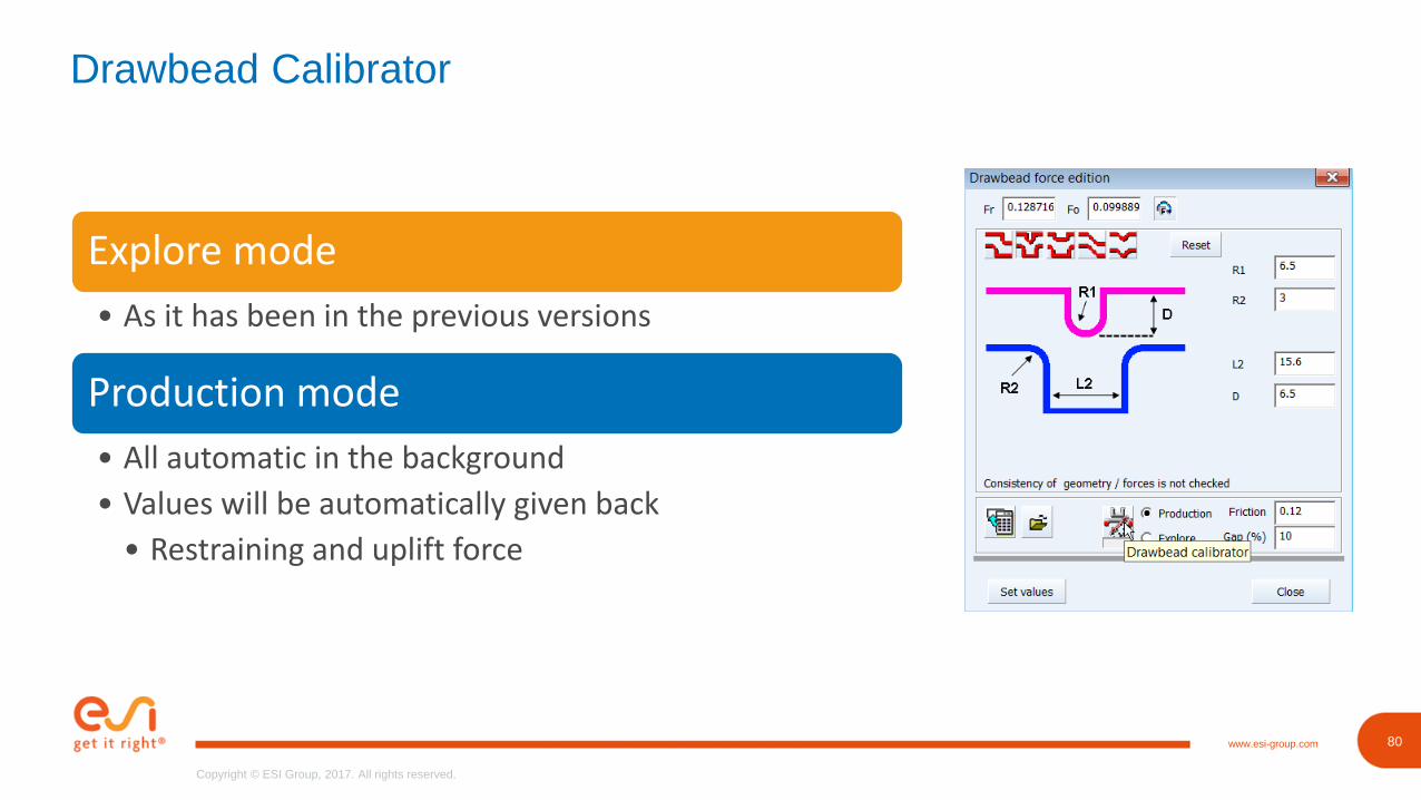
Drawbead Calibrator
Explore mode
• As it has been in the previous versions
Production mode
• All automatic in the background
• Values will be automatically given back
• Restraining and uplift force
83www.esi-group.com
Copyright © ESI Group, 2017. All rights reserved.
83
Copyright © ESI Group, 2017. All rights reserved.
www.esi-group.com
Tips & Tricks
Save Disk Space & Speed Up
84www.esi-group.com
Copyright © ESI Group, 2017. All rights reserved.
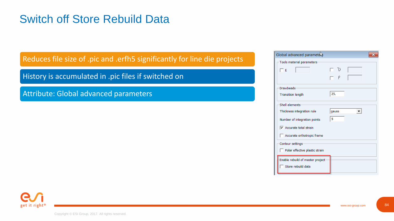
Switch off Store Rebuild Data
Reduces file size of .pic and .erfh5 significantly for line die projects
History is accumulated in .pic files if switched on
Attribute: Global advanced parameters
85www.esi-group.com
Copyright © ESI Group, 2017. All rights reserved.
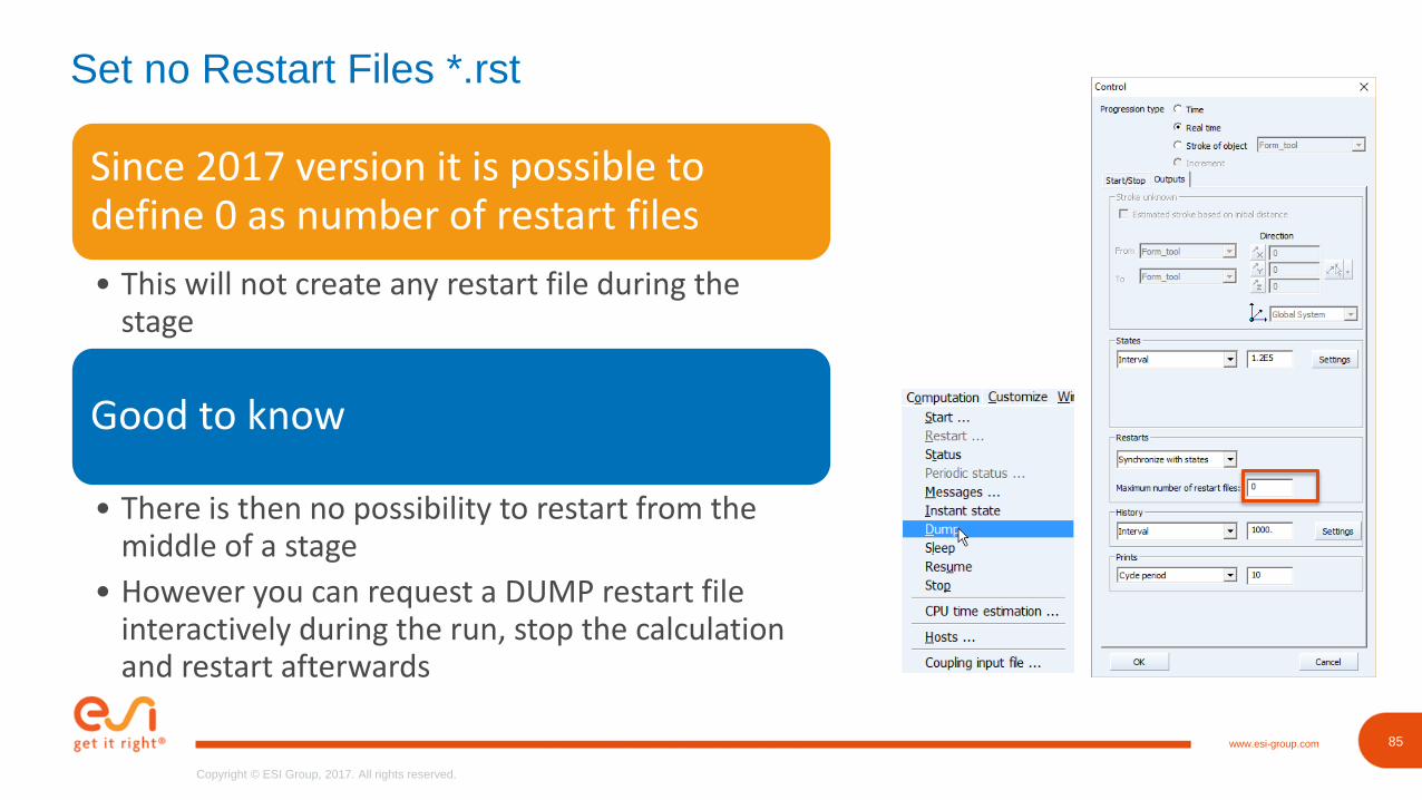
Set no Restart Files *.rst
Since 2017 version it is possible to define 0 as number of restart files
• This will not create any restart file during the stage
Good to know
• There is then no possibility to restart from the middle of a stage
• However you can request a DUMP restart file interactively during the run, stop the calculation and restart afterwards
86www.esi-group.com
Copyright © ESI Group, 2017. All rights reserved.
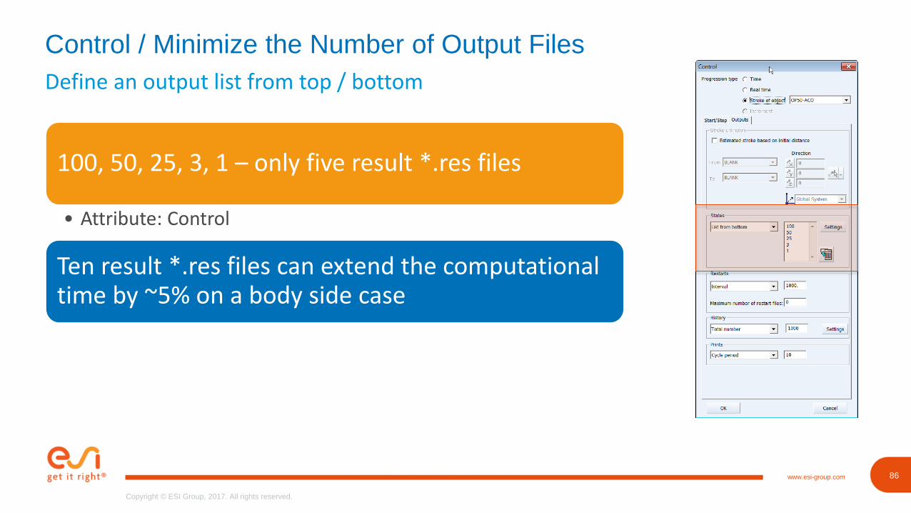
Define an output list from top / bottom
Control / Minimize the Number of Output Files
100, 50, 25, 3, 1 – only five result *.res files
• Attribute: Control
Ten result *.res files can extend the computational time by ~5% on a body side case

87www.esi-group.com
Copyright © ESI Group, 2017. All rights reserved.
87
Copyright © ESI Group, 2017. All rights reserved.
www.esi-group.com
Tips & Tricks
Speed Up
88www.esi-group.com
Copyright © ESI Group, 2017. All rights reserved.
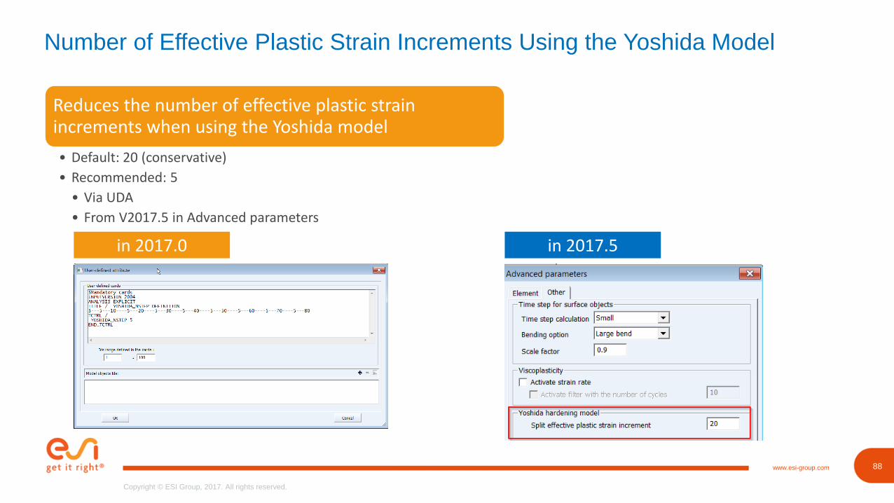
Number of Effective Plastic Strain Increments Using the Yoshida Model
Reduces the number of effective plastic strain increments when using the Yoshida model
• Default: 20 (conservative)
• Recommended: 5
• Via UDA
• From V2017.5 in Advanced parameters
in 2017.0 in 2017.5
90www.esi-group.com
Copyright © ESI Group, 2017. All rights reserved.
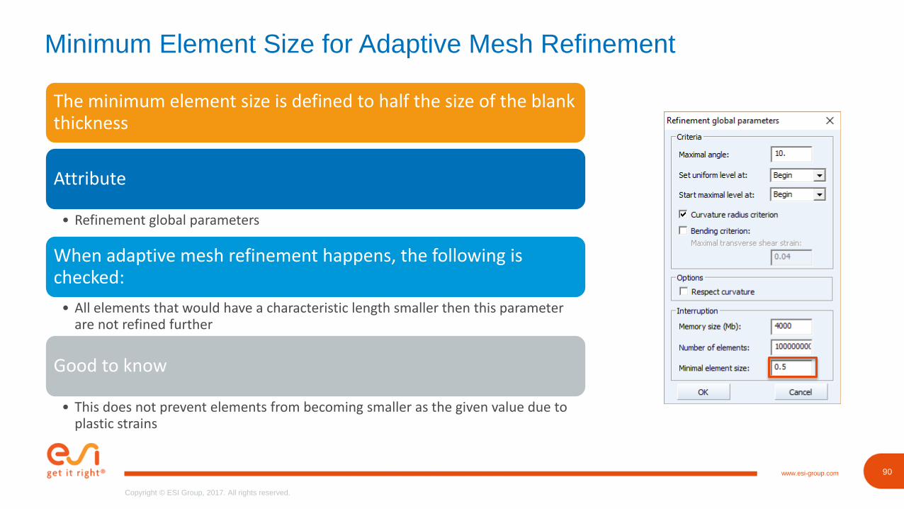
Minimum Element Size for Adaptive Mesh Refinement
The minimum element size is defined to half the size of the blank thickness
Attribute
• Refinement global parameters
When adaptive mesh refinement happens, the following is checked:
• All elements that would have a characteristic length smaller then this parameter are not refined further
Good to know
• This does not prevent elements from becoming smaller as the given value due to plastic strains
91www.esi-group.com
Copyright © ESI Group, 2017. All rights reserved.
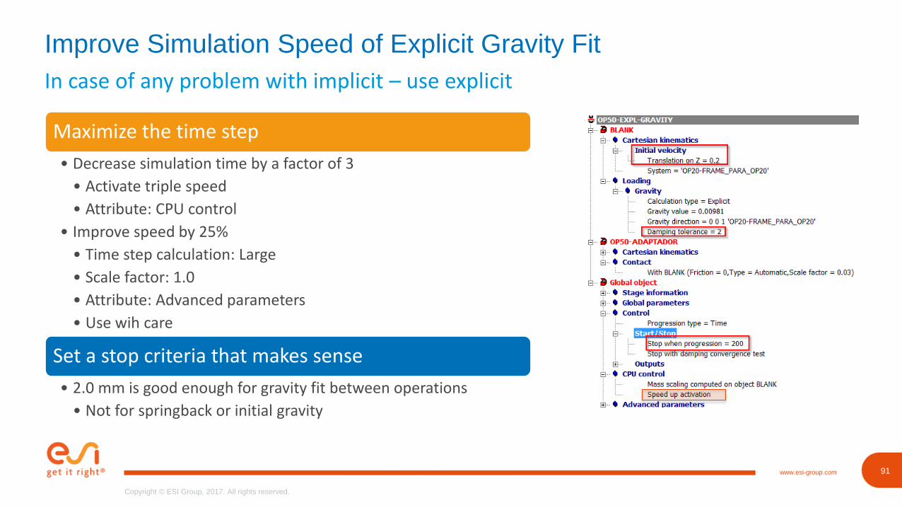
In case of any problem with implicit – use explicit
Improve Simulation Speed of Explicit Gravity Fit
Maximize the time step
• Decrease simulation time by a factor of 3
• Activate triple speed
• Attribute: CPU control
• Improve speed by 25%
• Time step calculation: Large
• Scale factor: 1.0
• Attribute: Advanced parameters
• Use wih care
Set a stop criteria that makes sense
• 2.0 mm is good enough for gravity fit between operations
• Not for springback or initial gravity
94www.esi-group.com
Copyright © ESI Group, 2017. All rights reserved.
94
Copyright © ESI Group, 2017. All rights reserved.
www.esi-group.com
Tips & Tricks
Avoid Stop on Error
95www.esi-group.com
Copyright © ESI Group, 2017. All rights reserved.
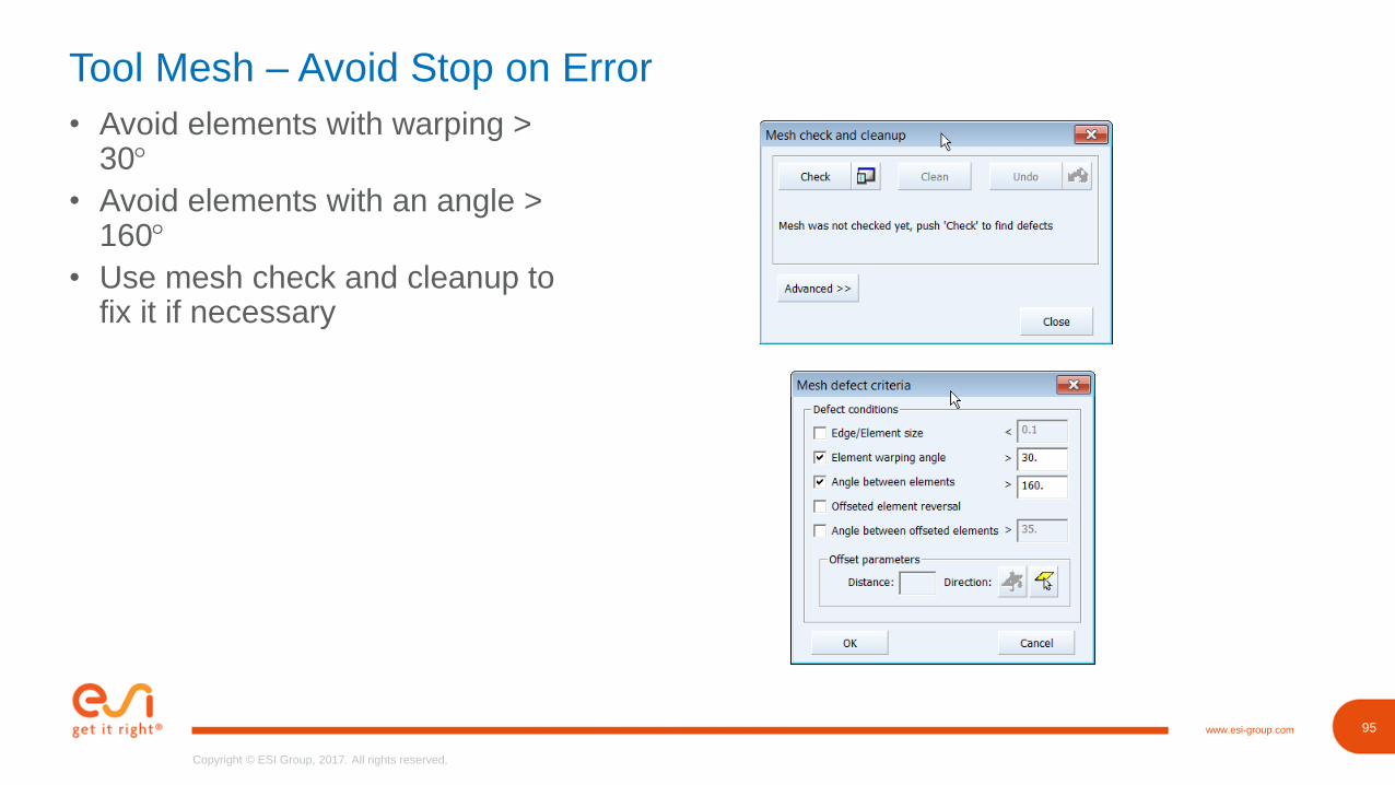
Tool Mesh – Avoid Stop on Error
• Avoid elements with warping > 30
• Avoid elements with an angle > 160
• Use mesh check and cleanup to fix it if necessary
99www.esi-group.com
Copyright © ESI Group, 2017. All rights reserved.
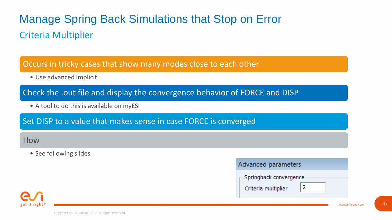
Criteria Multiplier
Manage Spring Back Simulations that Stop on Error
Occurs in tricky cases that show many modes close to each other
• Use advanced implicit
Check the .out file and display the convergence behavior of FORCE and DISP
• A tool to do this is available on myESI
Set DISP to a value that makes sense in case FORCE is converged
How
• See following slides
100www.esi-group.com
Copyright © ESI Group, 2017. All rights reserved.
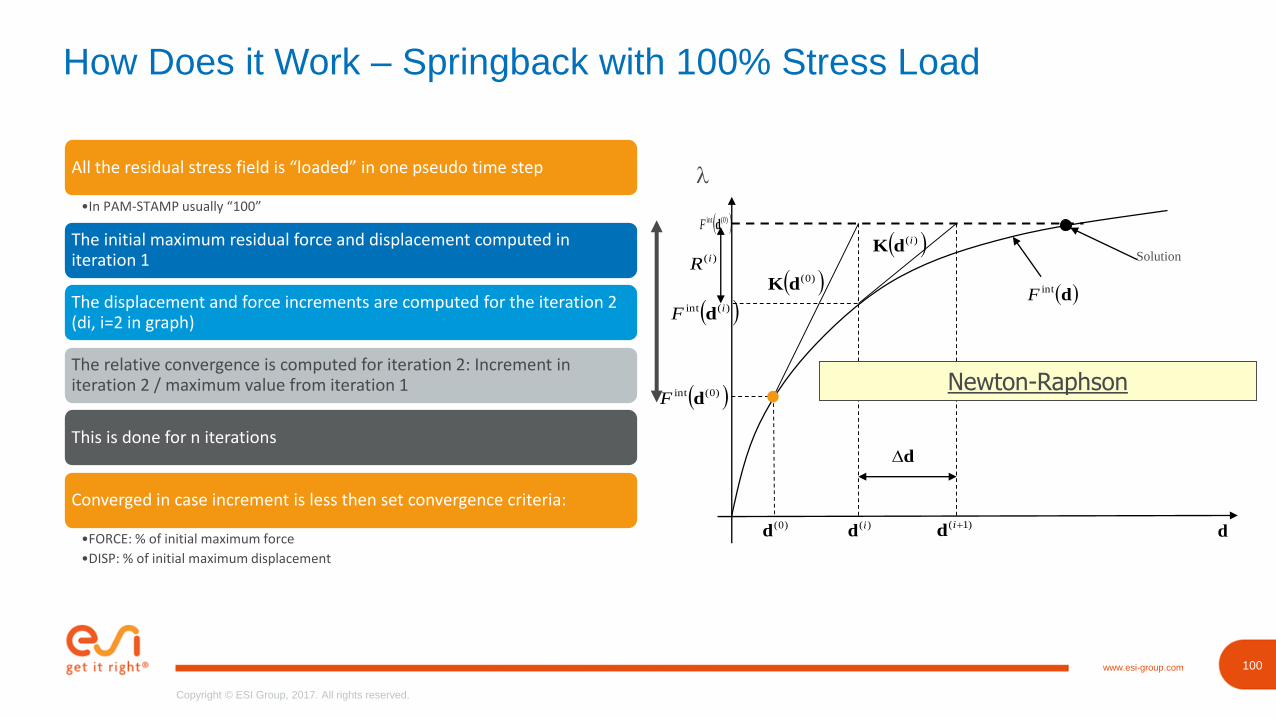
How Does it Work – Springback with 100% Stress Load
All the residual stress field is “loaded” in one pseudo time step
•In PAM-STAMP usually “100”
The initial maximum residual force and displacement computed in iteration 1
The displacement and force increments are computed for the iteration 2 (di, i=2 in graph)
The relative convergence is computed for iteration 2: Increment in iteration 2 / maximum value from iteration 1
This is done for n iterations
Converged in case increment is less then set convergence criteria:
•FORCE: % of initial maximum force
•DISP: % of initial maximum displacement
)0(intdF
Solution
d
)(id
)0(d d
dintF
)0(dK
)(idK
)0(intdF
)(int iF d
)(iR
)1( id
Newton-Raphson
l
101www.esi-group.com
Copyright © ESI Group, 2017. All rights reserved.
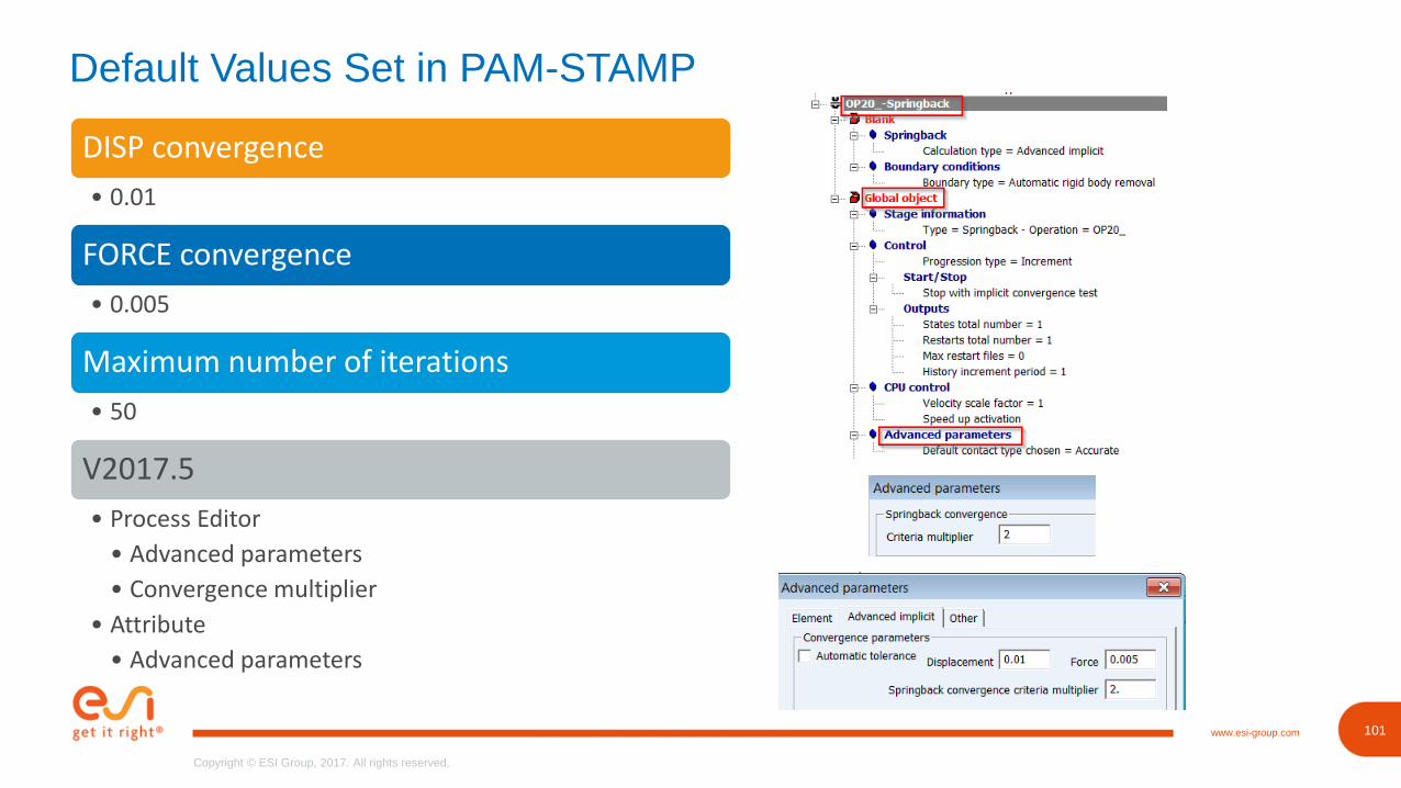
Default Values Set in PAM-STAMP
DISP convergence
• 0.01
FORCE convergence
• 0.005
Maximum number of iterations
• 50
V2017.5
• Process Editor
• Advanced parameters
• Convergence multiplier
• Attribute
• Advanced parameters
102www.esi-group.com
Copyright © ESI Group, 2017. All rights reserved.
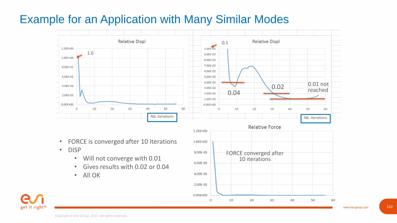
Example for an Application with Many Similar Modes
0.040.02 0.01 not
reached
Nb. iterationsNb. iterations
FORCE converged after 10 iterations
0.1
1.0
• FORCE is converged after 10 iterations• DISP
• Will not converge with 0.01• Gives results with 0.02 or 0.04• All OK
104www.esi-group.com
Copyright © ESI Group, 2017. All rights reserved.
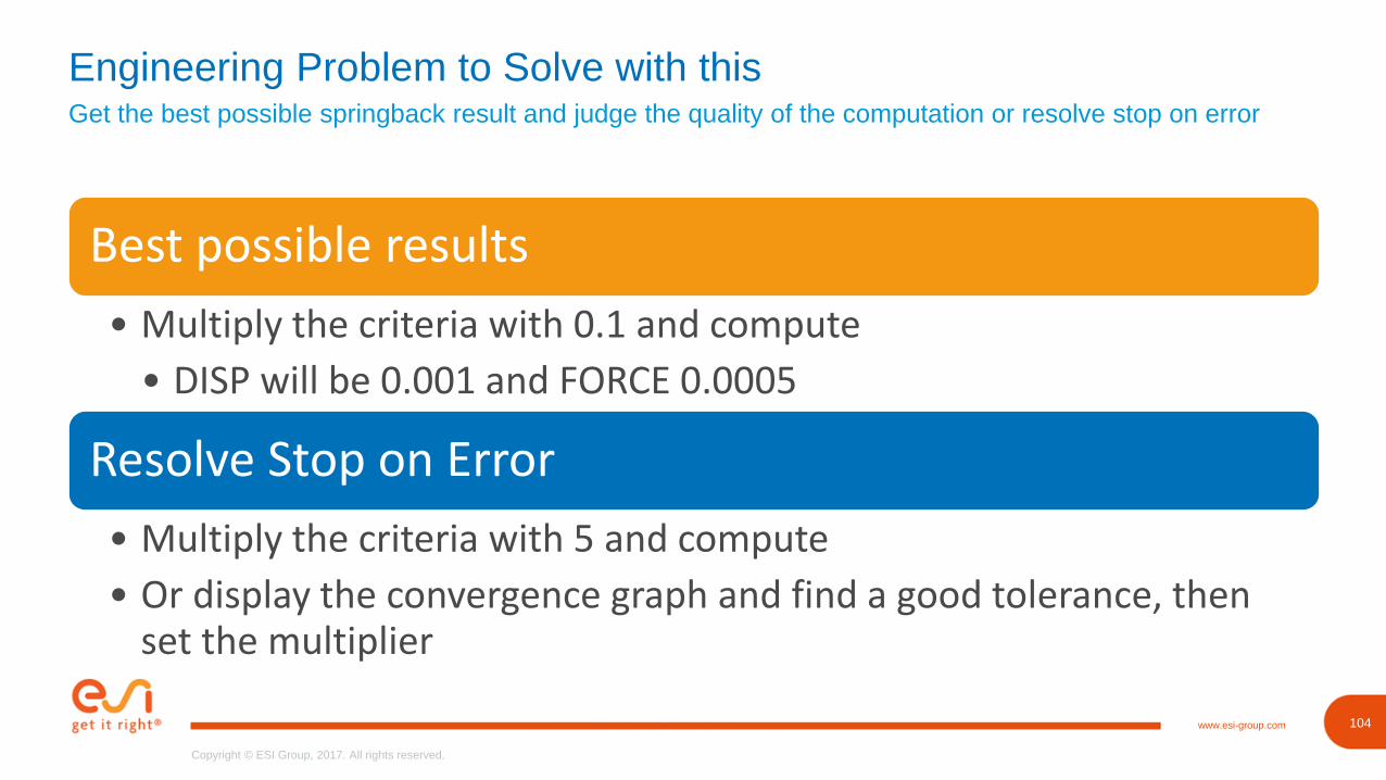
Get the best possible springback result and judge the quality of the computation or resolve stop on error
Engineering Problem to Solve with this
Best possible results
• Multiply the criteria with 0.1 and compute
• DISP will be 0.001 and FORCE 0.0005
Resolve Stop on Error
• Multiply the criteria with 5 and compute
• Or display the convergence graph and find a good tolerance, then set the multiplier
105www.esi-group.com
Copyright © ESI Group, 2017. All rights reserved.
105
Copyright © ESI Group, 2017. All rights reserved.
www.esi-group.com
Product Availability
106www.esi-group.com
Copyright © ESI Group, 2017. All rights reserved.
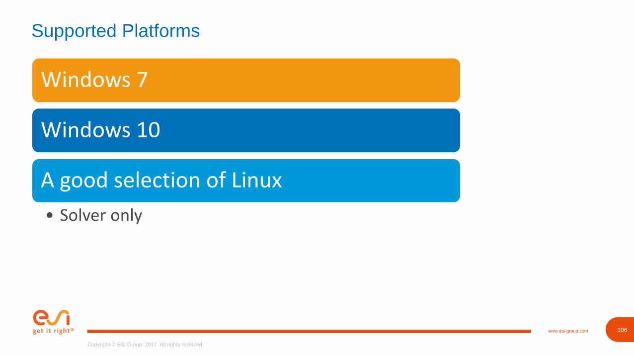
Supported Platforms
Windows 7
Windows 10
A good selection of Linux
• Solver only
107www.esi-group.com
Copyright © ESI Group, 2017. All rights reserved.
www.esi -group.com
Thank You
Recommended