WorkShop Audace
INSA ROUEN8 juin 2012

JEDEC standards for product level qualification
Global Standards for the Microelectronics Industry
Christian Gautier

Content
JEDEC overview
Environmental reliability stress test description
• JESD47H “Stress-Test-Driven Qualification of Integrated Circuits”
Physical Failure Modes per Stress Test & Acceleration factor
• JEP 122 “Failure Mechanisms and Models for Semiconductor Devices”
3

JEDEC (Joint Electron Device Engineering Council)
Independent semiconductor engineering trade organization
Founded in 1958
300 members companies (semiconductormanufacturers and suppliers)
48 committees and subcommittees
• JC-22 : Diodes and Thyristors
• JC-11 : Mechanical (Package Outlines) Standardization
• JC-15 : Thermal Characterization Techniques for Semiconductor Packages
• JC-25 : Transistors
• JC-14 : Quality and Reliability of Solid State Products
• …
4

Committee JC-14 “Quality and Reliability of Solid State Products”
Responsible for standardizing quality and reliability methodologies for solid state products used in commercial applications such as computers, automobiles, telecommunications equipment, etc,…
5 subcommittees
• JC-14.1 : Reliability Test Methods for Packaged Devices
• JC-14.2 : Wafer-Level Reliability
• JC-14.3 : Silicon Devices Reliability Qualification and Monitoring
• JC-14.4 : Quality Processes and Methods
• JC-14.7 : Gallium Arsenide Reliability and Quality Standards
5

Subcommittee JC-14.3 “Silicon Devices Reliability Qualification and Monitoring “
JESD47H .01“Stress-Test-Driven Qualification of Integrated Circuits”- April 2011
• Baseline set of acceptance tests for use in qualifying electronic components.
• These tests are capable of stimulating and precipitating semiconductor device and packaging failures. The objective is to precipitate failures in an accelerated manner compared to use conditions.
JESD94 “Application Specific Qualification using Knowledge Based Test Methodology” – July 2008
• Provide a method for developing an application specific reliability evaluation methodology
• It assumes that the failure mechanisms and models, relevant to the product being tested, are a known entity
JEP 122G : Failure Mechanisms and Models for Semiconductor Devices – October 2011
• List of failure mechanisms and their associated activation energies or acceleration factors
6

Content
JEDEC overview
Environmental reliability stress test description
• JESD47H “Stress-Test-Driven Qualification of Integrated Circuits”
Physical Failure Modes per Stress Test & Acceleration factor
• JEP 122 “Failure Mechanisms and Models for Semiconductor Devices”
7

From JESD-94: Application Specific Qualification Using Knowledge Based Test Methodology
Applications
Application Conditions
Operating
Life
(POH)*
Field
Lifetime
(Years)
Environmental
&
Power Cycles
Environmental
Relative
Humidity
Range(% RH)
Environmental
Temperature
Range (°C)
Operational
Temperature Cycle
Range (°C)
Chip Junction
Temperature
(Tj)
Typical/ Max.
(°C)
Device
Nominal
Operating
Voltage
(V)
Desk Top Computer
with Energy Saving
Features
13,000 hr 5 years Main: 1/ day
Mini: 17/ day
Short: 1/ day
10 - 80% 10° - 30°C Main: 20° - 60°C
Mini: 52° - 60 °C
Short : 40° - 60 °C
70°C / 105°C 12.0 V
High End Server 94,000 hr 11 years 4 / year 10 - 80% 10° - 30°C 14° - 55°C 70°C / 105°C 1.2 V
Avionic Electronics
in Cockpit
>150,000 hr ~ 23 years Power: 21,500
2.5 / day
5 - 80% -20° - 50°C 0° - 50°C 70°C / 105°C 3.3V / 5V
Telecom Hand Held 43,800 hr 5 years Talk: 20 / day
Standby/Off: 1/ day
10 - 95% -40° - 40°C Talk: 32° - 70°C
Standby / Off: 30° - 32°C
30°C / 70°C 1.8V / 3.3V
Telecom Uncontrolled 131,000 hr 15 years Talk: 20 / day
Environ: 1/ day
85% -40° - 85°C Power: Δ 85°C
Environ: Δ 25°C
85°C / 110°C 1.2 V
Telecom Controlled 131,000 hr 15 years Talk: 20 / day
Environ: 1/ day
70% 0° - 70°C Power: Δ 85°C
Environ: Δ 6°C
85°C / 110°C 1.2 V
Automotive
Underhood (Grade 0)
8200 hr 15 years Power: 5 / day 0 - 100% -40° - 125°C -40° - 150°C 100°C / 150°C 12.0 V
* POH (Power-On-Hours) value assumes worst case 100 % power-on over the life of the application; actual application use POH may be less
Application Conditions
8

Environmental reliability stress test flowJESD47H “Stress-Test-Driven Qualification of Integrated Circuits”
Preconditioning
Electrical meas. / Inspection*
*Inspection
e.g. SCAT
Thermal cyclingHumidity
Unbiased
Humidity
Biased
Temperature
Unbiased
Finished product
Electrical measurement/Inspection*
Temperature
biased
Electrical measurement/ Inspection*
9

Scope
To assess the sensitivity of non-hermetic packaged solid-state devices, after shipment (environmental stresses), to PCB mounting (hot convection reflow soldering)
Conditions are according to the observed Moisture Sensitivity Level (MSL)
PCB
PRECON Test JEDEC /JESD22-A113
10

SCAT (option)
Dry Bake (MSL1/2 not needed)
(125°C, 24 hr)
Temp. & Hum. Soak
85°C/85%
168 hrs
30°C/60%
6 hrs
30°C/60%
48 hrs
30°C/60%
96 hrs
30°C/60%
192 hrs
85°C/60%
168 hrs
TMCL (option)
(-40°C/60°C, 5X)
Convection reflow + Flux dip
Electr. M. (option)
SCAT (option)
MSL1 MSL6MSL5MSL4MSL3MSL2
Simulate Temp. changes by transport
Remove all moisture from the package
Simulate Moisture absorption in floor
Simulate soldering process
PRECON Flow
11
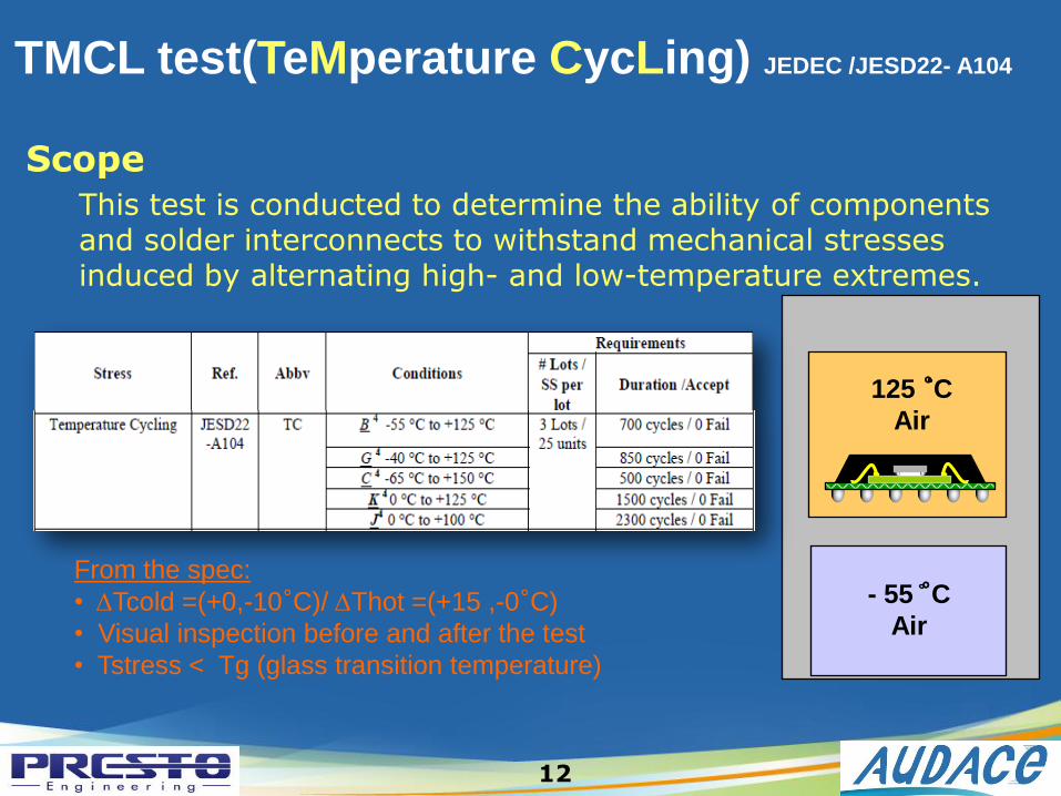
Scope
This test is conducted to determine the ability of components and solder interconnects to withstand mechanical stresses induced by alternating high- and low-temperature extremes.
- 55 °CAir
125 °CAir
TMCL test(TeMperature CycLing) JEDEC /JESD22- A104
From the spec:
• DTcold =(+0,-10°C)/ DThot =(+15 ,-0°C)
• Visual inspection before and after the test
• Tstress < Tg (glass transition temperature)
12

ScopeThis test method applies primarily to moisture resistance evaluations and robustness testing. Samples are subjected to a condensing or non condensing, highly humid atmosphere under pressure to force moisture into the package to uncover weaknesses such as delamination and metallization corrosion
From the spec:
• DT= +/- 2°C and DH= +/-5%
• Condensed water ( 1M/cm) NOT allowed to fall onto the specimen
• Contamination control is important : - cabinets: regular cleaning
- handling: suitable handcovering
• Tstress < Tg (glass transition temperature)
PPOT/UHST test JEDEC/JESD22-A118/A102
13

Accelerated intrusion of moisture
towards electrochemically sensitive areas(e.g. die surface: bond pad corrosion)
through the surrounding moulding compound
or directly via gaps, cracks and delaminated areas(as a result of Precon)
Moisture
Effect of PPOT/UHST
14

Scope
To evaluate the reliability of non-hermetic packaged solid-state devices in humid environments where temperature, humidity, and bias accelerate the penetration of moisture
From the spec:
• DT= +/- 2°C and DH= +/-5%
• Contamination control is important!
• Read point measurements (for all hum. tests):
- 48 hr (144 hr in sealed moisture bags)
Test THB/HAST JEDEC/ JESD22 -A101/110
15
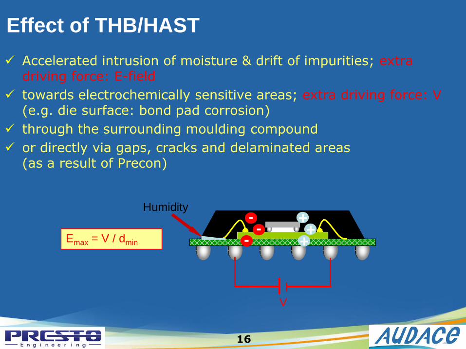
Humidity
Accelerated intrusion of moisture & drift of impurities; extra driving force: E-field
towards electrochemically sensitive areas; extra driving force: V(e.g. die surface: bond pad corrosion)
through the surrounding moulding compound
or directly via gaps, cracks and delaminated areas(as a result of Precon)
V
-
--
++
+Emax = V / dmin
Effect of THB/HAST
16

Scope
To asses the endurance of IC products when exposed to ahigh temperature for a long time period
HTSL test JEDEC/ JESD22-A103
From the spec:
• DT =(-0,+10°C)
• Read point measurements before 168 hours +
visual inspection before and after test
17

Scope
This test is used to determine the effects of biasconditions and temperature on solid state devicesover time.
It simulates the devices operating condition in anaccelerated way.
HTOL test JEDEC/JESD22-A108
From the spec:
• DT =+/-5°C• Read point measurements before 168 hours (96 hours if V>10V)
18

Environmental Tests & Conditions
Environmental Stress Test
Abbr. Specification Stress Conditions Requirements
Preconditioning PRECONJESD22-A113 per MSL,
1/2(a)/3/4/5(a)/6passlevel
Temperature Cycling Test
TMCL JESD22-A104-65°C to +150°C,
Unbiased (condition C)
500 cls3 x 0/25
Pressure Cooker test
PPOTJESD22-A102 121°C, 100 % RH,
Unbiased96 hr
3 x 0/25
Unsaturated Pressure Cooker
UHSTJESD22-A118 130°C, 85% RH,
Unbiased96 hr
3 x 0/25
Temperature Humidity Bias
THB JESD22-A10185°C, 85% RH,
Biased1000 hr3 x 0/25
Highly Accelerated Stress Test
HAST JESD22-A110130°C, 85% RH,
Biased96 hr
3 x 0/25
High Temperature Storage Test
HTSL JESD22-A103 150°C1000 hr3 x 0/25
High Temperature Operating Life
HTOL JESD22-A108150°C (junction),
Biased1000 hr3 x 0/77
19

• Heller 1700EXL Convection Reflow
• Oven with 7 temperature zone
PRECON : Hot convection reflow
20

Temperature cycling system test
-70
-55
-40
-25
-10
5
20
35
50
65
80
95
110
125
140
0 15 30 45 60
Tem
pera
ture
(°C
)
Time (minutes)
Package temp
Cycles
• 2 chambers oven (air to air)
• Transfer time between chambers : 10 s
• Rapid Thermal Variation within cold
chamber with ramps up to 20°C/mn
• Regulation : +/- 1 °C
• Net volume : 350 dm3
21

• Conditions : up to 160°C/up to 100%HR
• Regulation : +/- 0.1 °C & +/- 0.1%HR
• Net volume : up to 30 dm3
HAST/Autoclave systemTest
22

Temperature/Humidity system test
• Conditions : up to 180°C/up to 95%HR
• Regulation : +/- 0.3 °C & +/- 2%HR
• Net volume : up to 540 dm3
23

Temperature system test
• Condition : up to 200°C
• Regulation : +/- 1 °C
• Net volume : up to 700 dm3
24

Content
JEDEC overview
Environmental reliability stress test description
• JESD47H “Stress-Test-Driven Qualification of Integrated Circuits”
Physical Failure Modes per Stress Test & Acceleration factor
• JEP 122 “Failure Mechanisms and Models for Semiconductor Devices”
25

Coffin-Manson model
AF : Acceleration Factor
DTstress : Temperature swing during stress test
DTuse : Temperature swing during use
q : Coffin Manson exponent; failure mechanism dependent
• This model can be used to calculate life times for known failure mechanisms at use conditions, and to compare different stress conditions
• The temperature ranges must be corrected for the stress-free temperature range
q
use
stress
T
TAF
D
D
Acceleration by DT / Temperature cycling
26
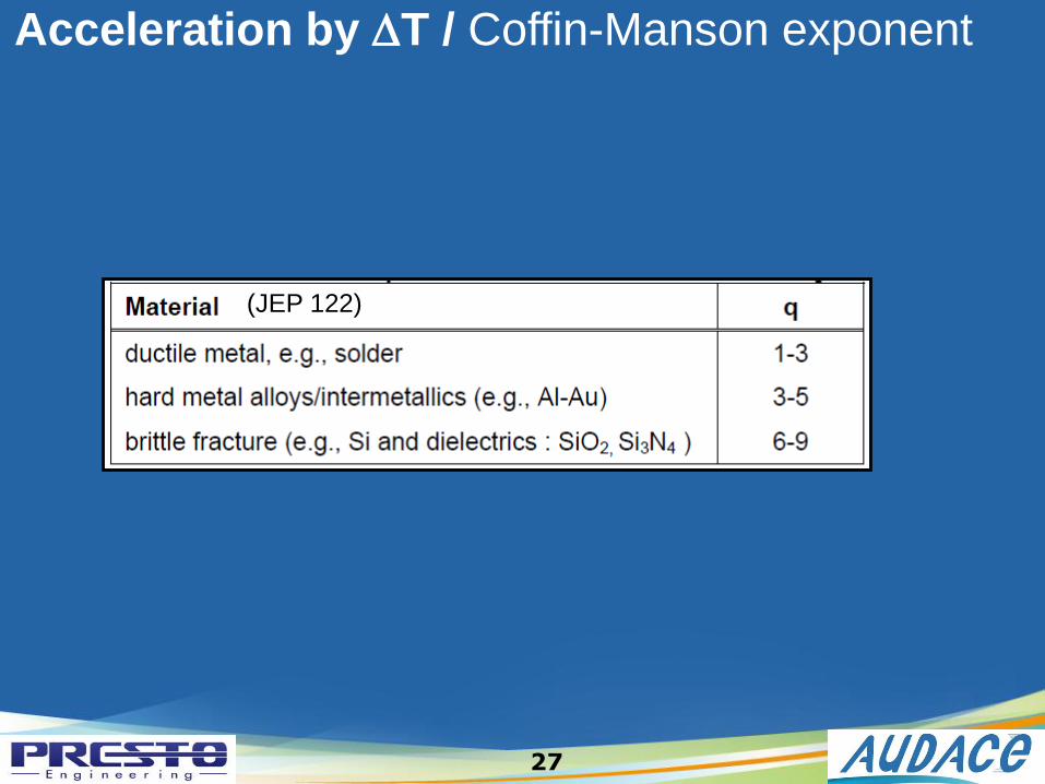
Acceleration by DT / Coffin-Manson exponent
(JEP 122)
27

Acceleration by T / Dry heat test
stressuseB
act
TTk
EAF
11exp
Arrhenius model :
AF Acceleration factorEact Activation energy; failure mechanism dependentTstress Temperature during stress testTuse Temperature during usekB Boltzmann’s constant = 8.62 x 10⁻⁵ eV/K
28

Peck model
f(V) Unknown function of voltage
AF Acceleration Factor
RHstress Relative humidity during stress test
RHuse Relative humidity during use
Eact Activation energy; failure mechanism dependent
Tstress Temperature during stress test
Tuse Temperature during use
kB Boltzmann’s constant = 8.62 x 10⁻⁵ eV/K
n Peck exponent; failure mechanism dependent
stressuseB
actn
use
stress
T
1
T
1
k
Eexp
RH
RHVfAF
Acceleration by RH, T, V / Damp heat test
29

f(V) =C(onstant), corrosion rate determined by electrochemical potential
E-field, corrosion rate determined by ionic transport
Failure Mechanism Exponent Activation Energy (eV) Reference
Aluminum corrosion when
chlorides are present2.7 0.7-0.8 JEP122
stressuseB
actn
use
stress
T
1
T
1
k
Eexp
RH
RHVfAF
Acceleration by RH, T, V / Peck exponent
30

Solder flow out
Delamination
Change in body flatness
Internal package crack
Popcorn gap
31
Examples of Mechanical Failure Modes // PRECON

External package crack
Solder fatigue/ ball crack
Delamination
Wire break
Passivation crack
Die crack
32
Examples of Thermo Mechanical Failure Modes // TMCL

TMCL: solder ball crack (JEP 122)
Ductile solder fatigue-induced crack network
33

TMCL: die crack (JEP 122)
Brittle failure (Si fracture)
34

TMCL: passivation crack (JEP 122)
Brittle failure (top-side passivation fracture)
35

TMCL: delamination & solder fatigue cracking (JEP122)
Interfacial delamination
36

Dry corrosion
Dendrite formation & leakage
37
Examples of Moisture Related Failure Modes
Aluminum bond pad corrosion
(JEP 122)
Electrochemical migration between leads on a QFP
(JEP 122)
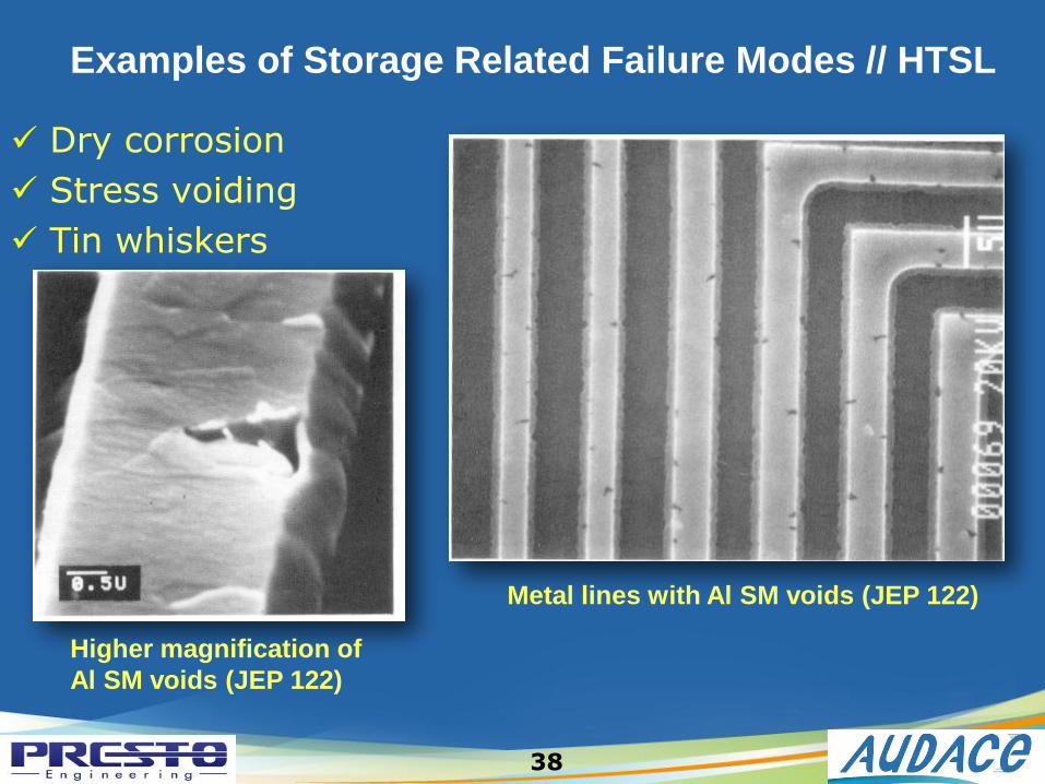
Dry corrosion
Stress voiding
Tin whiskers
38
Examples of Storage Related Failure Modes // HTSL
Metal lines with Al SM voids (JEP 122)
Higher magnification of
Al SM voids (JEP 122)

HTSL : Tin whiskers growing (JEP122)
39

Electromigration
Oxide breakdown
40
Examples of HTOL Related Failure Modes
EM void in a Cu line under a via
(JEP 122)
Time-Dependent Dielectric Breakdown
gate oxide (JEP 122)

THANK FOR YOUR ATTENTION
Recommended