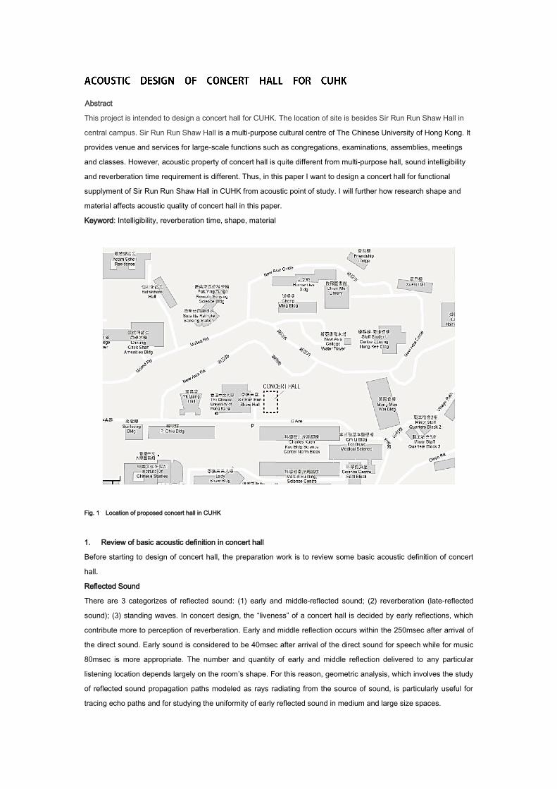
Abstract
This project is intended to design a concert hall for CUHK. The location of site is besides Sir Run Run Shaw Hall in
central campus. Sir Run Run Shaw Hall is a multi-purpose cultural centre of The Chinese University of Hong Kong. It
provides venue and services for large-scale functions such as congregations, examinations, assemblies, meetings
and classes. However, acoustic property of concert hall is quite different from multi-purpose hall, sound intelligibility
and reverberation time requirement is different. Thus, in this paper I want to design a concert hall for functional
supplyment of Sir Run Run Shaw Hall in CUHK from acoustic point of study. I will further how research shape and
material affects acoustic quality of concert hall in this paper.
Keyword: Intelligibility, reverberation time, shape, material
Fig. 1 Location of proposed concert hall in CUHK
1. Review of basic acoustic definition in concert hall
Before starting to design of concert hall, the preparation work is to review some basic acoustic definition of concert
hall.
Reflected Sound
There are 3 categorizes of reflected sound: (1) early and middle-reflected sound; (2) reverberation (late-reflected
sound); (3) standing waves. In concert design, the “liveness” of a concert hall is decided by early reflections, which
contribute more to perception of reverberation. Early and middle reflection occurs within the 250msec after arrival of
the direct sound. Early sound is considered to be 40msec after arrival of the direct sound for speech while for music
80msec is more appropriate. The number and quantity of early and middle reflection delivered to any particular
listening location depends largely on the room’s shape. For this reason, geometric analysis, which involves the study
of reflected sound propagation paths modeled as rays radiating from the source of sound, is particularly useful for
tracing echo paths and for studying the uniformity of early reflected sound in medium and large size spaces.
Echoes
Echoes are reflections that can be heard distinctly and separately from the early reflected and reverberant sound.
Design criteria for echo detection depend on the type of space being constructed. For most general purposes involving
speech communication, echoes are normally heard due to intense reflection arriving 40 msec and later after the direct
sound signal has reached the listener. In other words, the difference in path length between the direct sound and the
reflected sound is at least 13.8m, corresponding to a propagation time of 40 msc or greater. In concert hall, echoes
are most commonly detected in the front rows of an auditorium and on stage. This results from the front row being
farthest from the rear wall, thus generating the largest path length difference between direct sound and the sound
reflection from the rear wall or the combination of the ceiling and the rear wall.
Reverberation
Reverberation is directly proportional to room volume, inversely proportional to the surface area, and inversely
proportional to the amount of sound-absorbing material. Excess reverberation results in blurring of sounds and can
reduce speech intelligibility. It is possible to reduce reverberation by the following means: (1) adding sound-absorbing
material; (2) reducing room volume; (3) increasing surface area.
Reverberation time is measure used to quantify reverberation and is the time required for sound reflections to decay
60 dB.
Acoustic Shadow
Due to some obstruction, some space can’t get first reflected sound. These area
calls acoustic shadow area (Refer to Fig.2). Acoustic shadow usually appears in
space underneath of terraced seating which needs to be avoided in concert hall
design.
Fig. 2 Forming of acoustic shadow
Focusing
The cardinal rule in the design of rooms is to avoid sound reflections that focus in the plane of listening. A focusing
surface concentrates sound energy, which may then be intense enough to be perceived as an echo. Surfaces such as
domes, barrel-vaulted ceilings, and concave rear walls can cause sound focusing and are notorious for generating
strong echoes
2. Define volume and area of concert hall
First I would need to define the volume and dimension of concert
hall. Fig. 3 depicts typical volume requirement for different types of
performance spaces. We can see from fig. 3 the volume of concert
hall is 10-11.4 times required no. of seats.
The proposed concert hall is supposed to accommodate 800 seats.
The volume of concert hall V=800*10=8000m³
Ceiling height also plays an important role in delivering early
reflections in music halls. Typical ceiling heights yielding an adequate
density of early sound are: (1) 500 seats: 9-11m; (2)1500
seats:13.5-16m; (3)2500 seats:18-21m. (Source from: Architrectural
acoustics principles and practice, 1999)
Typically, the maximum ceiling height (h) can be determined from
h= [3√(V/T500)] *0,85
We can get expected best reverberation time of 8000m³ at 500 Hz is 1.6s (from Fig.4). h=[3√(8000/1.6)] *0,85,
h=14.1.
So the maximum ceiling height of 800 seats is 14.1m
The minimum area of proposed concert hall S=V/h, S=8000/14.1=567m²
So the minimum area of proposed concert hall for 800 seats is 567m².
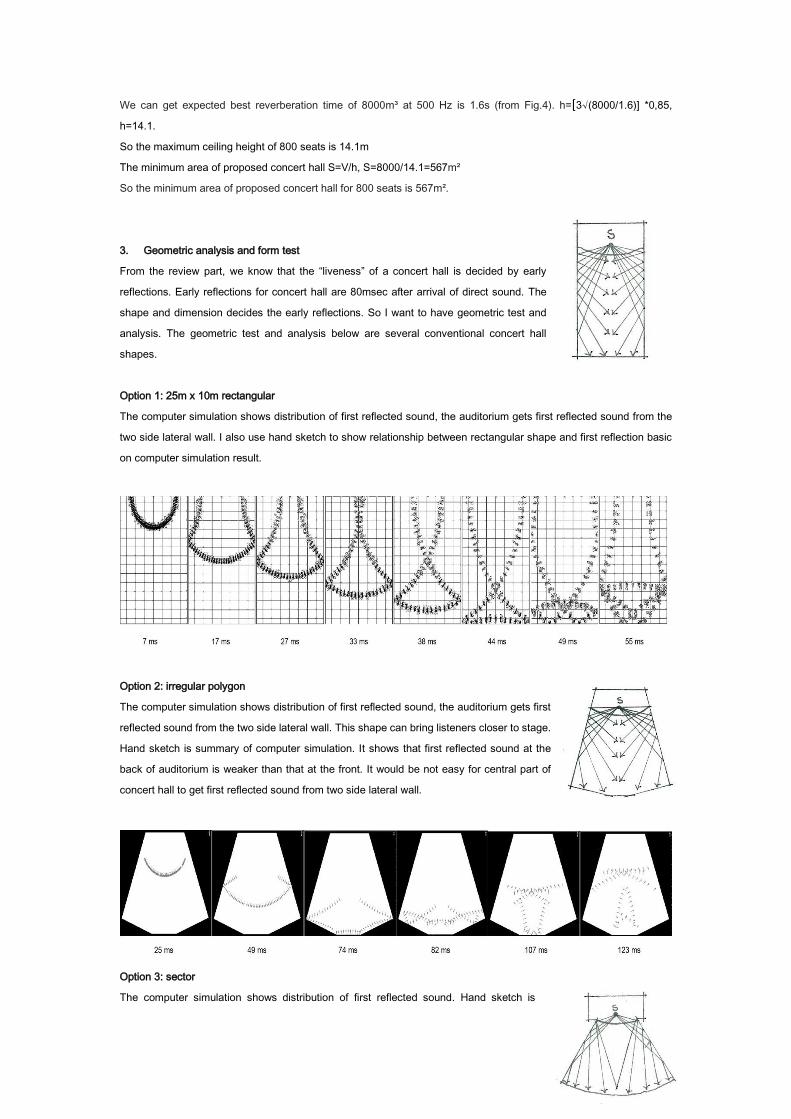
3. Geometric analysis and form test
From the review part, we know that the “liveness” of a concert hall is decided by early
reflections. Early reflections for concert hall are 80msec after arrival of direct sound. The
shape and dimension decides the early reflections. So I want to have geometric test and
analysis. The geometric test and analysis below are several conventional concert hall
shapes.
Option 1: 25m x 10m rectangular
The computer simulation shows distribution of first reflected sound, the auditorium gets first reflected sound from the
two side lateral wall. I also use hand sketch to show relationship between rectangular shape and first reflection basic
on computer simulation result.
Option 2: irregular polygon
The computer simulation shows distribution of first reflected sound, the auditorium gets first
reflected sound from the two side lateral wall. This shape can bring listeners closer to stage.
Hand sketch is summary of computer simulation. It shows that first reflected sound at the
back of auditorium is weaker than that at the front. It would be not easy for central part of
concert hall to get first reflected sound from two side lateral wall.
Option 3: sector
The computer simulation shows distribution of first reflected sound. Hand sketch is
summary of computer simulation. We can see both from computer simulation and hand sketch that the center of
auditorium is very difficult to get first reflected sound from lateral wall. With the angle of sector increases, it is more and
more difficult to get first reflected sound from lateral wall.
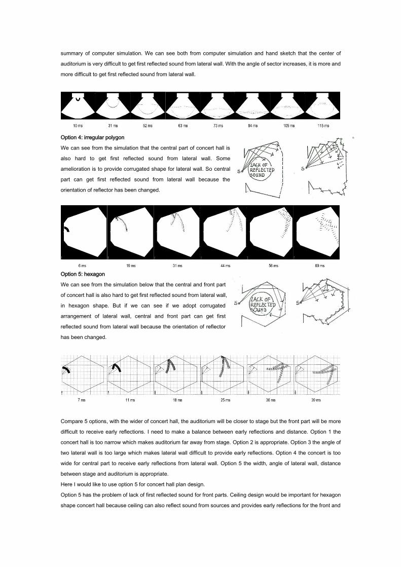
Option 4: irregular polygon
We can see from the simulation that the central part of concert hall is
also hard to get first reflected sound from lateral wall. Some
amelioration is to provide corrugated shape for lateral wall. So central
part can get first reflected sound from lateral wall because the
orientation of reflector has been changed.
Option 5: hexagon
We can see from the simulation below that the central and front part
of concert hall is also hard to get first reflected sound from lateral wall,
in hexagon shape. But if we can see if we adopt corrugated
arrangement of lateral wall, central and front part can get first
reflected sound from lateral wall because the orientation of reflector
has been changed.
Compare 5 options, with the wider of concert hall, the auditorium will be closer to stage but the front part will be more
difficult to receive early reflections. I need to make a balance between early reflections and distance. Option 1 the
concert hall is too narrow which makes auditorium far away from stage. Option 2 is appropriate. Option 3 the angle of
two lateral wall is too large which makes lateral wall difficult to provide early reflections. Option 4 the concert is too
wide for central part to receive early reflections from lateral wall. Option 5 the width, angle of lateral wall, distance
between stage and auditorium is appropriate.
Here I would like to use option 5 for concert hall plan design.
Option 5 has the problem of lack of first reflected sound for front parts. Ceiling design would be important for hexagon
shape concert hall because ceiling can also reflect sound from sources and provides early reflections for the front and
middle part of concert hall.
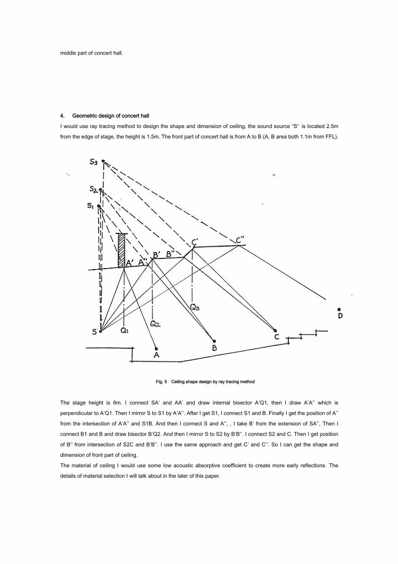
4. Geometric design of concert hall
I would use ray tracing method to design the shape and dimension of ceiling, the sound source “S“ is located 2.5m
from the edge of stage, the height is 1.5m. The front part of concert hall is from A to B (A, B area both 1.1m from FFL).
Fig. 5 Ceiling shape design by ray tracing method
The stage height is 6m. I connect SA’ and AA’ and draw internal bisector A’Q1, then I draw A’A’’ which is
perpendicular to A’Q1. Then I mirror S to S1 by A’A’’. After I get S1, I connect S1 and B. Finally I get the position of A’’
from the intersection of A’A’’ and S1B. And then I connect S and A’’, , I take B’ from the extension of SA’’, Then I
connect B1 and B and draw bisector B’Q2. And then I mirror S to S2 by B’B’’. I connect S2 and C. Then I get position
of B’’ from intersection of S2C and B’B’’. I use the same approach and get C’ and C’’. So I can get the shape and
dimension of front part of ceiling.
The material of ceiling I would use some low acoustic absorptive coefficient to create more early reflections. The
details of material selection I will talk about in the later of this paper.
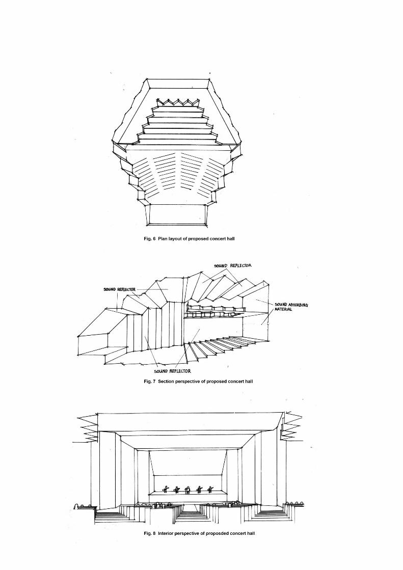

Here are hand sketch drawing of plan, section and interior perspective of concert hall I designed.
This plan is from basic hexagon. Length of side is 17m. This concert hall has 800 seats. The area of concert hall is 600
m2 (>567 m2) Ceiling height is from 3.5m to 11m (<14.1m).
The ground level is gradually elevated to fulfill the visual requirement. The front part of ceiling is designed according to
ray trace method. The back part of ceiling is corrugated shape to enhance early reflection of middle part of concert hall.
The rear wall uses sound absorbing material to avoid echo. The other walls, ceilings and ground I will use sound
reflecting material to increase reverberation time and benefit first sound reflection because long reverberation time
benefits sound quality of concert hall.
The front part of lateral wall is corrugated shape to benefit the first sound reflection of front and middle part of
auditorium.
The depth of terraced seating is not deep to avoid sound shadow occur in the space underneath terraced seating.
For the concert hall design, the space underneath terraced seating is
better not to be deep to avoid acoustic shadow. In this design case, the
depth “d” is 5m, the height of terraced seating “h” is 5.5m, d<h.
The research data (hand sketch right) shows concert hall depth needs to
be smaller than clear height of space underneath terraced seating. But for
multi-function hall d<2h would be acceptable. (Source from 建筑声环境)
5. Acoustic Simulation
After I finish the conceptual design of concert hall, I would use computer tool to make acoustic simulation to find the
defect and make improvement for the design. And I would like to analyse the distribution of reverberation time and
echo in concert hall. This simulation below I did is by ecotect. The sound source is from center of stage, the height is
1.5m from FFL
.
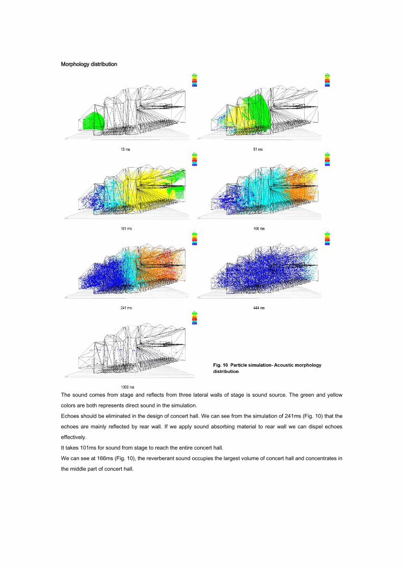
Morphology distribution
The sound comes from stage and reflects from three lateral walls of stage is sound source. The green and yellow
colors are both represents direct sound in the simulation.
Echoes should be eliminated in the design of concert hall. We can see from the simulation of 241ms (Fig. 10) that the
echoes are mainly reflected by rear wall. If we apply sound absorbing material to rear wall we can dispel echoes
effectively.
It takes 101ms for sound from stage to reach the entire concert hall.
We can see at 166ms (Fig. 10), the reverberant sound occupies the largest volume of concert hall and concentrates in
the middle part of concert hall.
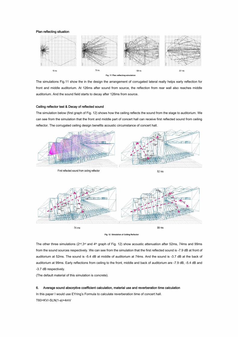
Plan reflecting situation
The simulations Fig.11 show the in the design the arrangement of corrugated lateral really helps early reflection for
front and middle auditorium. At 126ms after sound from source, the reflection from rear wall also reaches middle
auditorium. And the sound field starts to decay after 126ms from source.
Ceiling reflector test & Decay of reflected sound
The simulation below (first graph of Fig. 12) shows how the ceiling reflects the sound from the stage to auditorium. We
can see from the simulation that the front and middle part of concert hall can receive first reflected sound from ceiling
reflector. The corrugated ceiling design benefits acoustic circumstance of concert hall.
The other three simulations (2nd,3rd and 4th graph of Fig. 12) show acoustic attenuation after 52ms, 74ms and 99ms
from the sound sources respectively. We can see from the simulation that the first reflected sound is -7.9 dB at front of
auditorium at 52ms. The sound is -5.4 dB at middle of auditorium at 74ms. And the sound is -3.7 dB at the back of
auditorium at 99ms. Early reflections from ceiling to the front, middle and back of auditorium are -7.9 dB, -5.4 dB and
-3.7 dB respectively.
(The default material of this simulation is concrete).
6. Average sound absorptive coefficient calculation, material use and reverberation time calculation
In this paper I would use EYring’s Formula to calculate reverberation time of concert hall.
T60=KV/-SLN(1-a)+4mV
“V” is the volume of room (m3)
“S” is the surface of all indoor surfaces (m2)
“a” is the sound absorption coefficient of all indoor surfaces
4m is the air sound absorption coefficient
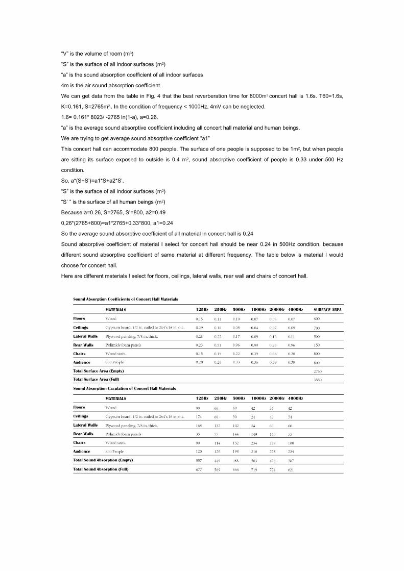
We can get data from the table in Fig. 4 that the best reverberation time for 8000m3 concert hall is 1.6s. T60=1.6s,
K=0.161, S=2765m2,. In the condition of frequency < 1000Hz, 4mV can be neglected.
1.6= 0.161* 8023/ -2765 ln(1-a), a=0.26.
“a” is the average sound absorptive coefficient including all concert hall material and human beings.
We are trying to get average sound absorptive coefficient “a1”
This concert hall can accommodate 800 people. The surface of one people is supposed to be 1m2, but when people
are sitting its surface exposed to outside is 0.4 m2, sound absorptive coefficient of people is 0.33 under 500 Hz
condition.
So, a*(S+S’)=a1*S+a2*S’,
“S” is the surface of all indoor surfaces (m2)
“S’ ” is the surface of all human beings (m2)
Because a=0.26, S=2765, S’=800, a2=0.49
0,26*(2765+800)=a1*2765+0.33*800, a1=0.24
So the average sound absorptive coefficient of all material in concert hall is 0.24
Sound absorptive coefficient of material I select for concert hall should be near 0.24 in 500Hz condition, because
different sound absorptive coefficient of same material at different frequency. The table below is material I would
choose for concert hall.
Here are different materials I select for floors, ceilings, lateral walls, rear wall and chairs of concert hall.
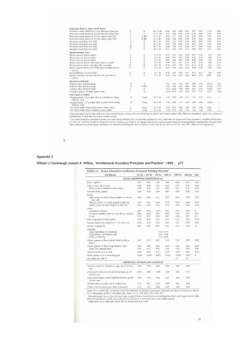
The reference of sound coefficient of concert hall material refers to appendix 1,2 and 3.
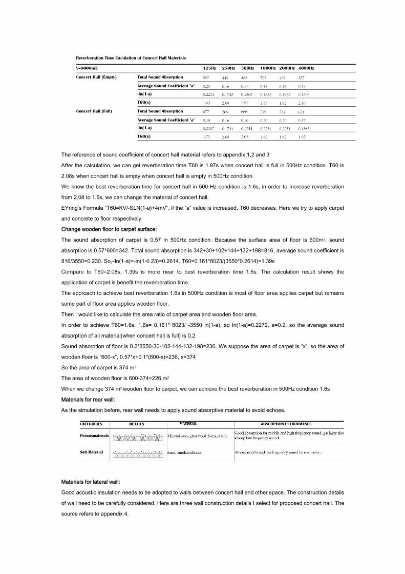
After the calculation, we can get reverberation time T60 is 1.97s when concert hall is full in 500Hz condition. T60 is
2.08s when concert hall is empty when concert hall is empty in 500Hz condition.
We know the best reverberation time for concert hall in 500 Hz condition is 1.6s, in order to increase reverberation
from 2.08 to 1.6s, we can change the material of concert hall.
EYring’s Formula “T60=KV/-SLN(1-a)+4mV”, if the “a” value is increased, T60 decreases. Here we try to apply carpet
and concrete to floor respectively.
Change wooden floor to carpet surface:
The sound absorption of carpet is 0.57 in 500Hz condition. Because the surface area of floor is 600m2, sound
absorption is 0.57*600=342. Total sound absorption is 342+30+102+144+132+198=816, average sound coefficient is
816/3550=0.230. So,–ln(1-a)=-ln(1-0.23)=0.2614. T60=0.161*8023/(3550*0.2614)=1.39s
Compare to T60=2.08s, 1.39s is more near to best reverberation time 1.6s. The calculation result shows the
application of carpet is benefit the reverberation time.
The approach to achieve best reverberation 1.6s in 500Hz condition is most of floor area applies carpet but remains
some part of floor area applies wooden floor.
Then I would like to calculate the area ratio of carpet area and wooden floor area.
In order to achieve T60=1.6s. 1.6s= 0.161* 8023/ -3550 ln(1-a), so ln(1-a)=0.2272, a=0.2. so the average sound
absorption of all material(when concert hall is full) is 0.2.
Sound absorption of floor is 0.2*3550-30-102-144-132-198=236. We suppose the area of carpet is “x”, so the area of
wooden floor is “600-x”, 0.57*x+0.1*(600-x)=236, x=374
So the area of carpet is 374 m2
The area of wooden floor is 600-374=226 m2
When we change 374 m2 wooden floor to carpet, we can achieve the best reverberation in 500Hz condition 1.6s
Materials for rear wall:
As the simulation before, rear wall needs to apply sound absorptive material to avoid echoes.
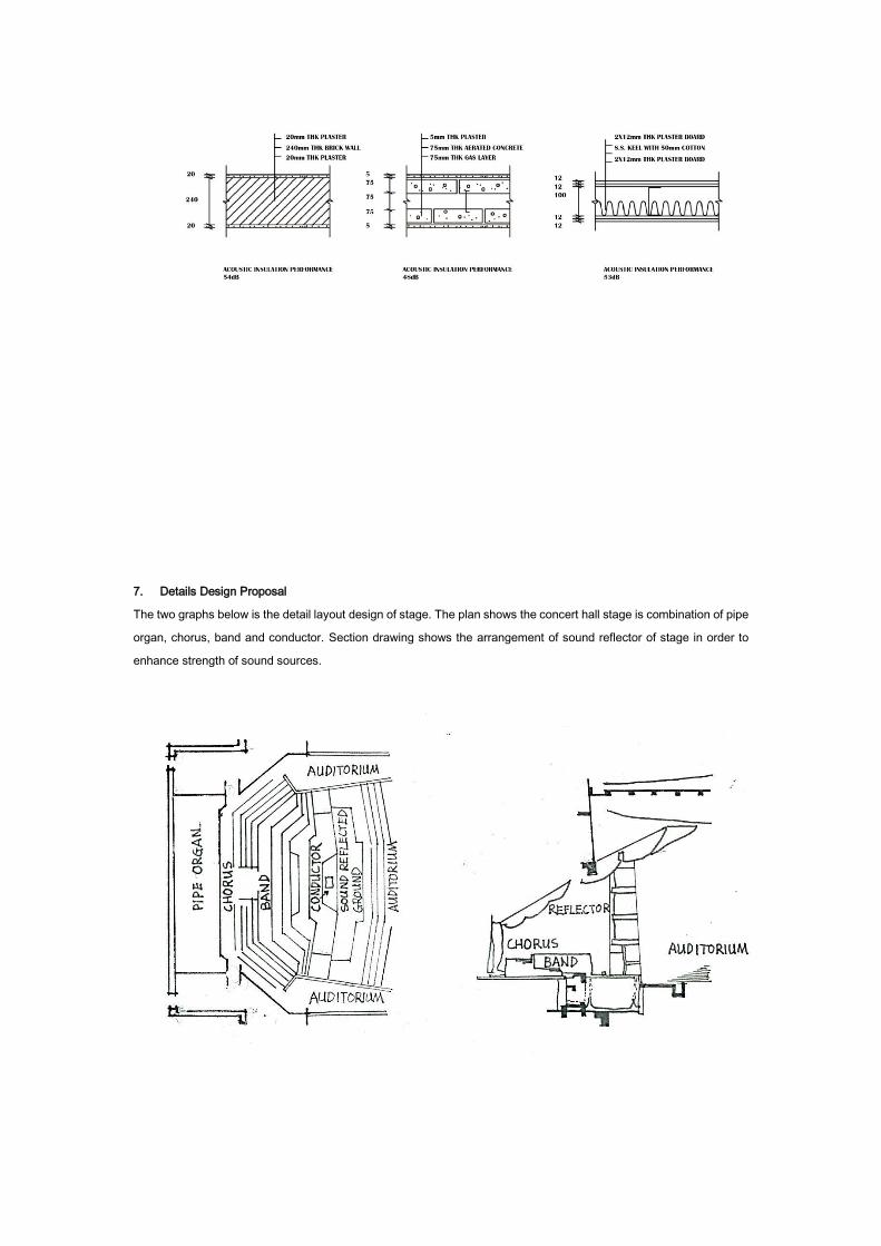
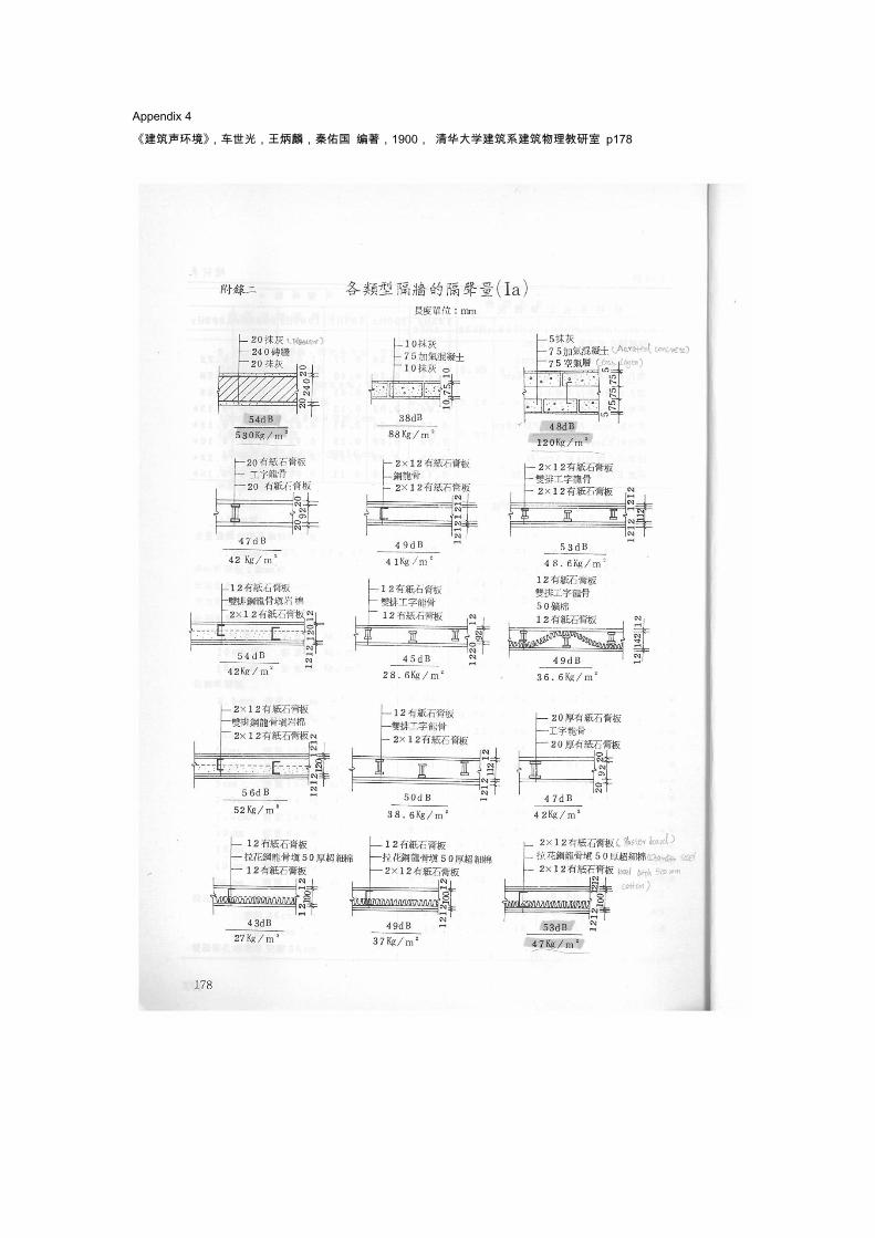
Materials for lateral wall:
Good acoustic insulation needs to be adopted to walls between concert hall and other space. The construction details
of wall need to be carefully considered. Here are three wall construction details I select for proposed concert hall. The
source refers to appendix 4.
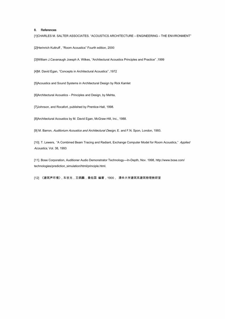
7. Details Design Proposal
The two graphs below is the detail layout design of stage. The plan shows the concert hall stage is combination of pipe
organ, chorus, band and conductor. Section drawing shows the arrangement of sound reflector of stage in order to
enhance strength of sound sources.
8. References
[1]CHARLES M. SALTER ASSOCIATES. “ACOUSTICS ARCHITECTURE – ENGINEERING – THE ENVIRONMENT”
[2]Herinrich Kuttruff , “Room Acoustics” Fourth edition, 2000
[3]William J.Cavanaugh Joesph A. Wilkes, “Architectural Acoustics Principles and Practice” ,1999
[4]M. David Egan, “Concepts in Architectural Acoustics” ,1972
[5]Acoustics and Sound Systems in Architectural Design by Rick Kamlet
[6]Architectural Acoustics – Principles and Design, by Mehta,
[7]Johnson, and Rocafort, published by Prentice-Hall, 1998.
[8]Architectural Acoustics by M. David Egan, McGraw-Hill, Inc., 1988.
[9] M. Barron, Auditorium Acoustics and Architectural Design, E. and F.N. Spon, London, 1993.
[10]. T. Lewers, “A Combined Beam Tracing and Radiant, Exchange Computer Model for Room Acoustics,” Applied
Acoustics, Vol. 38, 1993
[11]. Bose Corporation, Auditioner Audio Demonstrator Technology—In-Depth, Nov. 1998, http://www.bose.com/
technologies/prediction_simulation/html/principle.html.
[12] 《建筑声环境》,车世光,王炳麟,秦佑国 编著,1900, 清华大学建筑系建筑物理教研室
9. Appendix
Appendix 1
William J.Cavanaugh Joesph A. Wilkes, “Architectural Acoustics Principles and Practice” ,1999, p78
Appendix 2
William J.Cavanaugh Joesph A. Wilkes, “Architectural Acoustics Principles and Practice” ,1999, p79
Appendix 3
William J.Cavanaugh Joesph A. Wilkes, “Architectural Acoustics Principles and Practice” ,1999, p77
Appendix 4
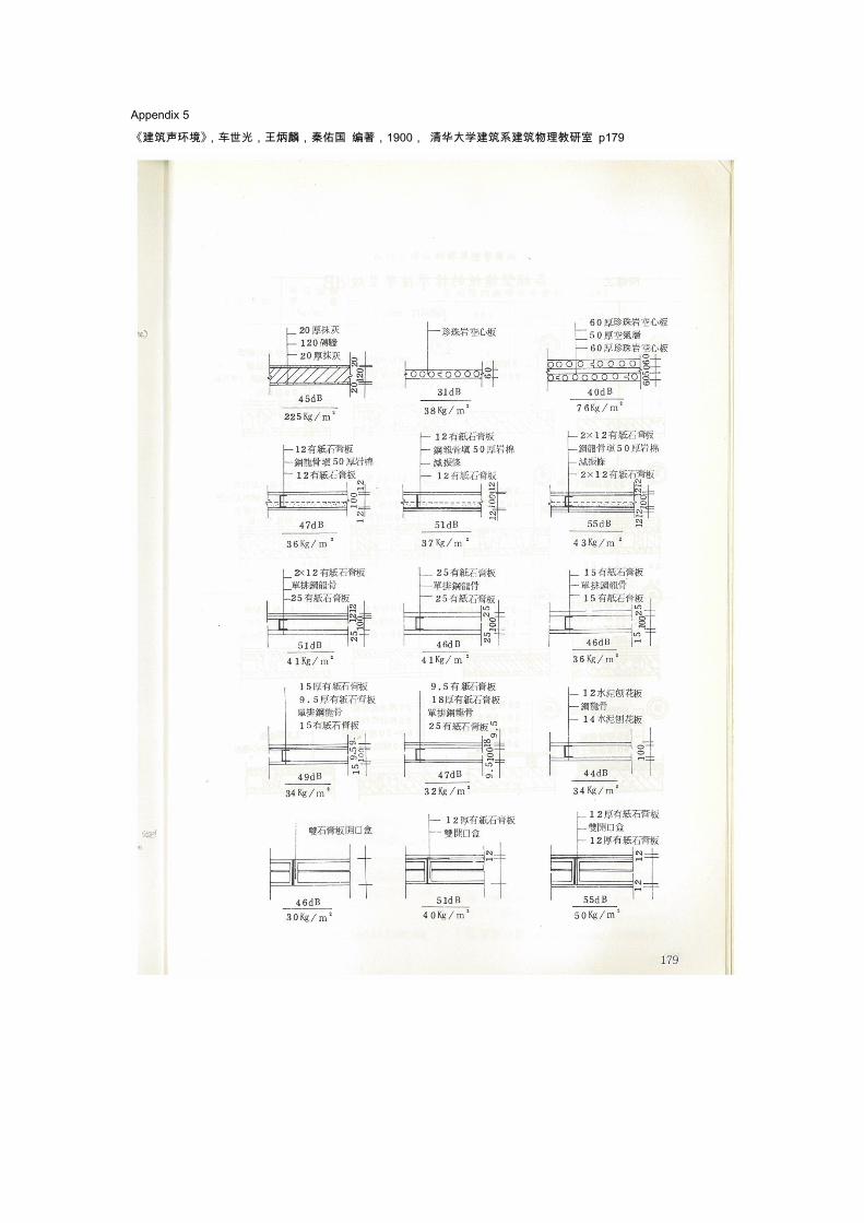
《建筑声环境》,车世光,王炳麟,秦佑国 编著,1900, 清华大学建筑系建筑物理教研室 p178
Appendix 5
《建筑声环境》,车世光,王炳麟,秦佑国 编著,1900, 清华大学建筑系建筑物理教研室 p179
Recommended