Embed Size (px)
Citation preview

Решения WANDL и NorthStarдля операторов
Александр Беспалов
системный инженер
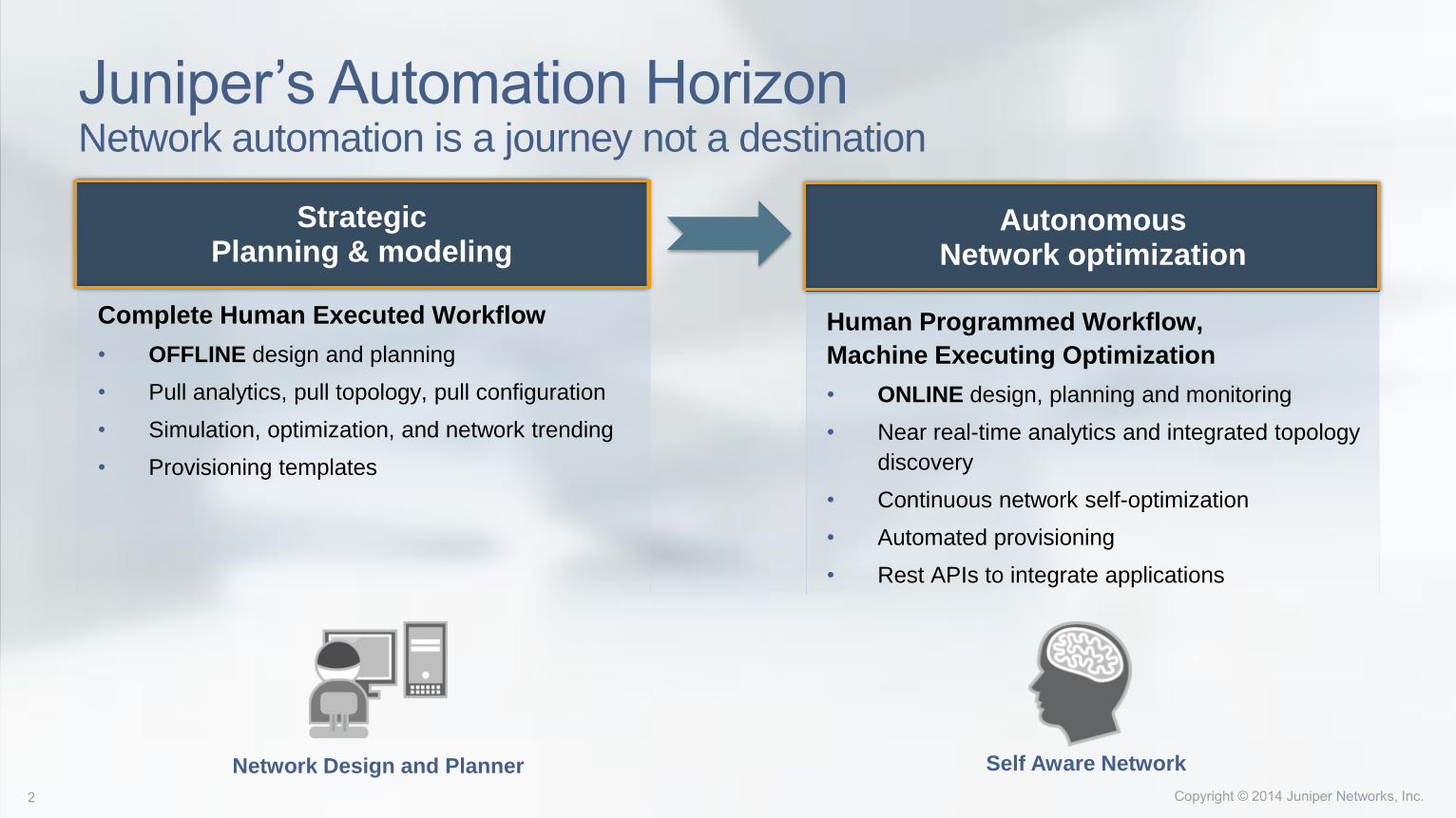
Juniper’s Automation Horizon Network automation is a journey not a destination
Human Programmed Workflow,
Machine Executing Optimization
• ONLINE design, planning and monitoring
• Near real-time analytics and integrated topology
discovery
• Continuous network self-optimization
• Automated provisioning
• Rest APIs to integrate applications
Complete Human Executed Workflow
• OFFLINE design and planning
• Pull analytics, pull topology, pull configuration
• Simulation, optimization, and network trending
• Provisioning templates
Strategic Planning & modeling
AutonomousNetwork optimization
Network Design and Planner Self Aware Network

WANDL IP/MPLS View
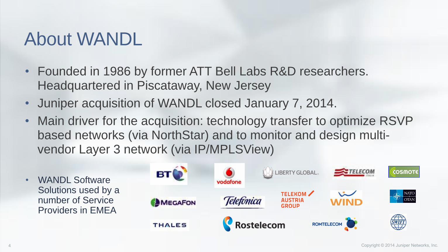
About WANDL
• Founded in 1986 by former ATT Bell Labs R&D researchers. Headquartered in Piscataway, New Jersey
• Juniper acquisition of WANDL closed January 7, 2014.
• Main driver for the acquisition: technology transfer to optimize RSVP based networks (via NorthStar) and to monitor and design multi-vendor Layer 3 network (via IP/MPLSView)
• WANDL Software Solutions used by a number of Service Providers in EMEA
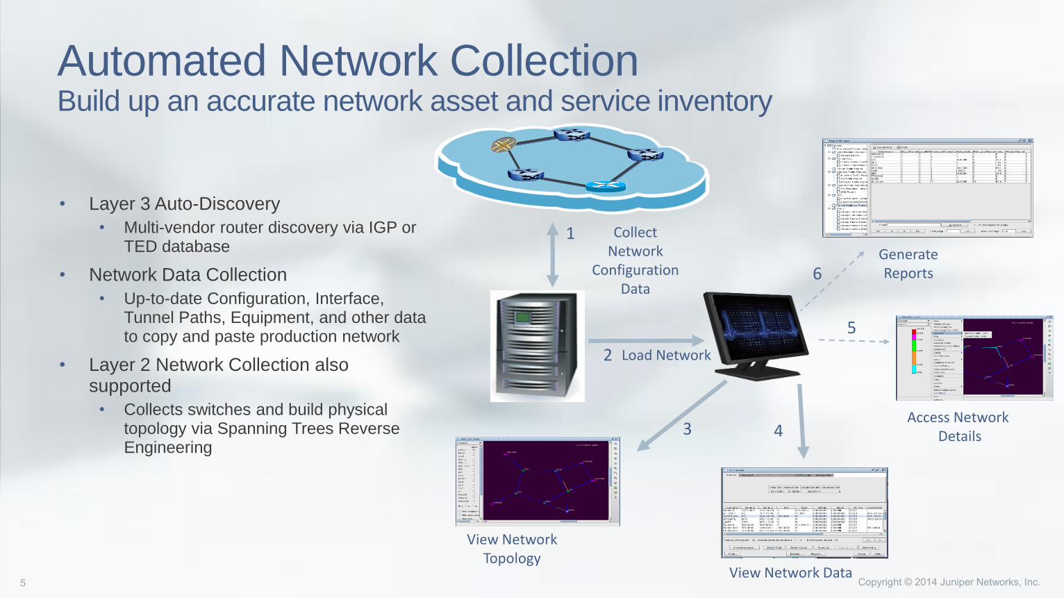
Automated Network CollectionBuild up an accurate network asset and service inventory
• Layer 3 Auto-Discovery
• Multi-vendor router discovery via IGP or TED database
• Network Data Collection
• Up-to-date Configuration, Interface, Tunnel Paths, Equipment, and other data to copy and paste production network
• Layer 2 Network Collection also supported
• Collects switches and build physical topology via Spanning Trees Reverse Engineering
1
2
3 4
5
6
Collect Network
ConfigurationData
Load Network
View NetworkTopology
View Network Data
Access NetworkDetails
GenerateReports
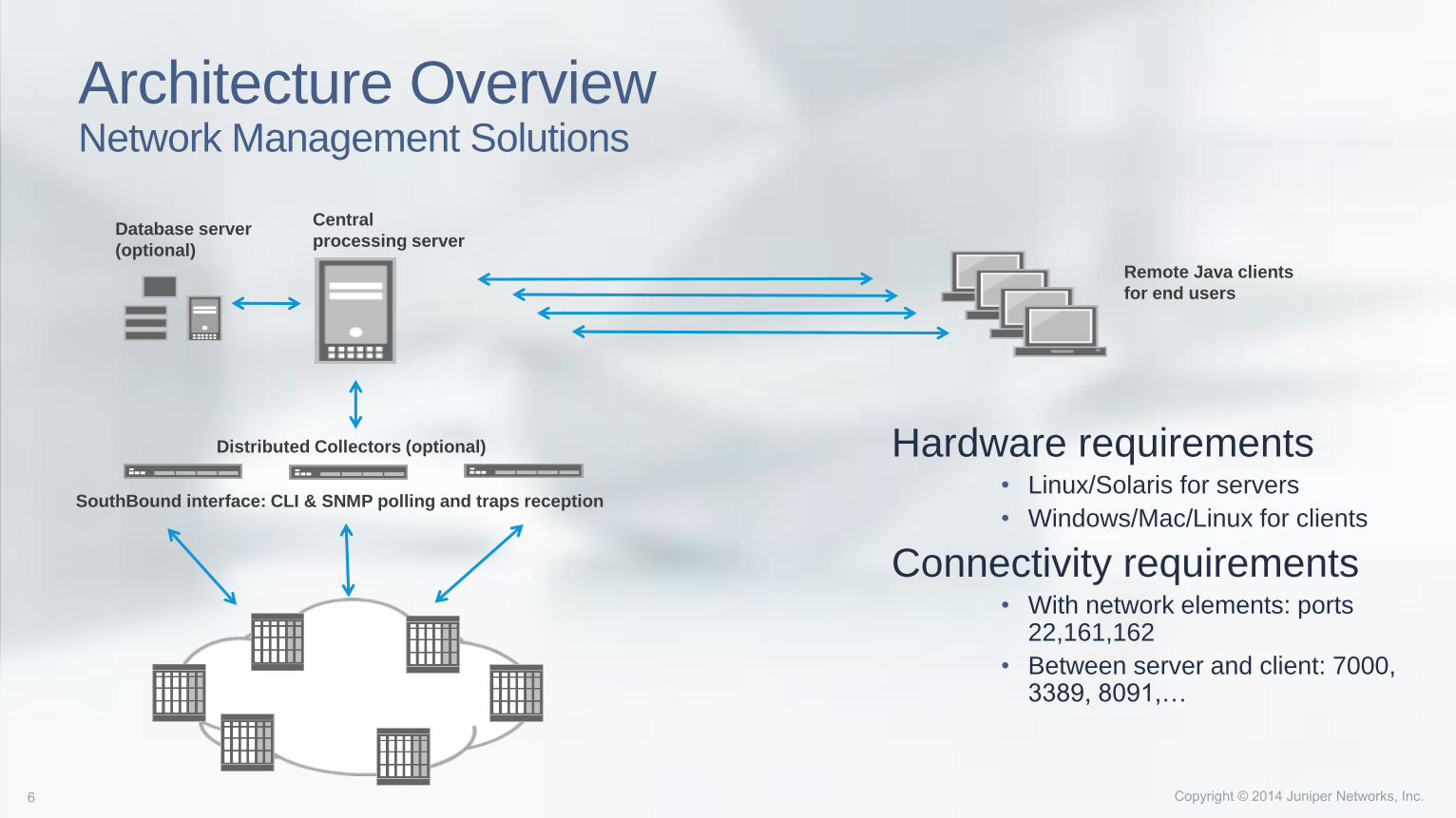
Architecture OverviewNetwork Management Solutions
Hardware requirements• Linux/Solaris for servers
• Windows/Mac/Linux for clients
Connectivity requirements• With network elements: ports
22,161,162
• Between server and client: 7000, 3389, 8091,…
SouthBound interface: CLI & SNMP polling and traps reception
Distributed Collectors (optional)
Central
processing serverDatabase server
(optional)
Remote Java clients
for end users
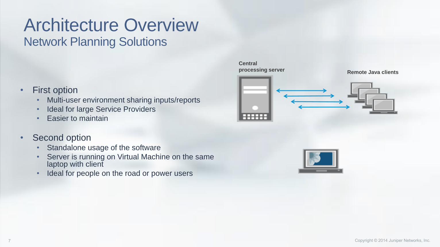
Architecture OverviewNetwork Planning Solutions
• First option• Multi-user environment sharing inputs/reports
• Ideal for large Service Providers
• Easier to maintain
• Second option• Standalone usage of the software
• Server is running on Virtual Machine on the same laptop with client
• Ideal for people on the road or power users
Central
processing server Remote Java clients

IP/MPLS View Data Model
• IP/MPLS View Data model is based on a number of tables: • Project file (mandatory)
• Router table (mandatory)
• Link table (mandatory)
• Traffic matrix table (mandatory)
• Interface table (optional)
• Router type table (optional)
• Tunnel table (optional)
• …
• Most IP/MPLS View input and output files are either CSV or text files• However traffic information stored in MySQL database for the Performance Management module
• No “strict” API for Southbound or Northbound interfaces
• Every set of IP/MPLS View input files has a unique runcode, aka extension. All files for a given network normally share the same runcode
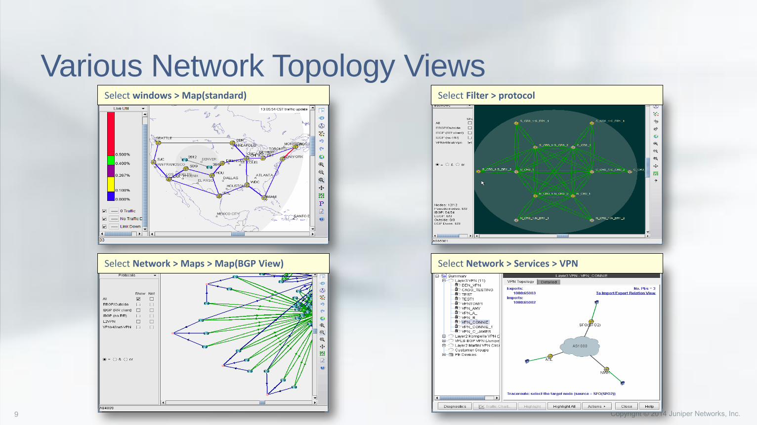
Various Network Topology ViewsSelect Filter > protocol
Select Network > Maps > Map(BGP View) Select Network > Services > VPN
Select windows > Map(standard)
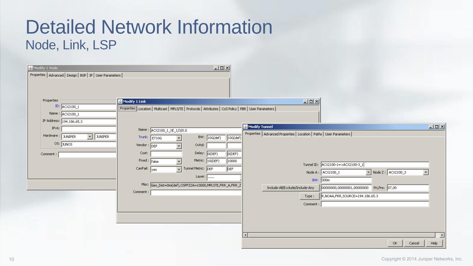
Detailed Network InformationNode, Link, LSP
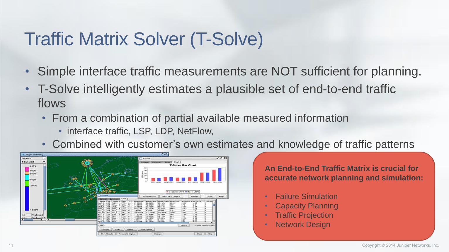
Traffic Matrix Solver (T-Solve)
• Simple interface traffic measurements are NOT sufficient for planning.
• T-Solve intelligently estimates a plausible set of end-to-end traffic flows• From a combination of partial available measured information
• interface traffic, LSP, LDP, NetFlow,
• Combined with customer’s own estimates and knowledge of traffic patterns
An End-to-End Traffic Matrix is crucial for
accurate network planning and simulation:
• Failure Simulation
• Capacity Planning
• Traffic Projection
• Network Design
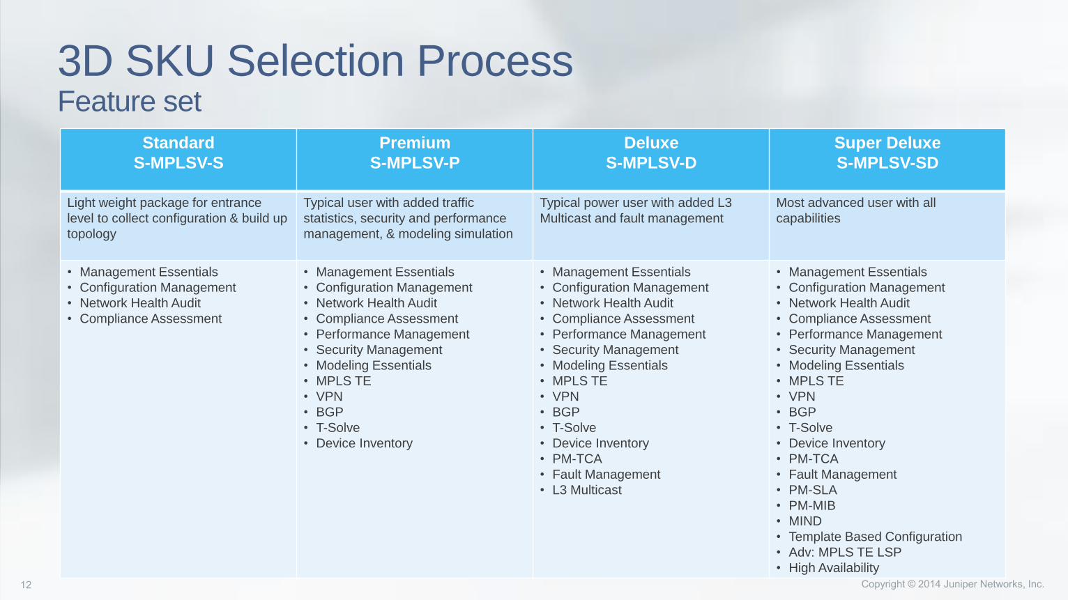
3D SKU Selection ProcessFeature set
Standard
S-MPLSV-S
Premium
S-MPLSV-P
Deluxe
S-MPLSV-D
Super Deluxe
S-MPLSV-SD
Light weight package for entrance
level to collect configuration & build up
topology
Typical user with added traffic
statistics, security and performance
management, & modeling simulation
Typical power user with added L3
Multicast and fault management
Most advanced user with all
capabilities
• Management Essentials
• Configuration Management
• Network Health Audit
• Compliance Assessment
• Management Essentials
• Configuration Management
• Network Health Audit
• Compliance Assessment
• Performance Management
• Security Management
• Modeling Essentials
• MPLS TE
• VPN
• BGP
• T-Solve
• Device Inventory
• Management Essentials
• Configuration Management
• Network Health Audit
• Compliance Assessment
• Performance Management
• Security Management
• Modeling Essentials
• MPLS TE
• VPN
• BGP
• T-Solve
• Device Inventory
• PM-TCA
• Fault Management
• L3 Multicast
• Management Essentials
• Configuration Management
• Network Health Audit
• Compliance Assessment
• Performance Management
• Security Management
• Modeling Essentials
• MPLS TE
• VPN
• BGP
• T-Solve
• Device Inventory
• PM-TCA
• Fault Management
• PM-SLA
• PM-MIB
• MIND
• Template Based Configuration
• Adv: MPLS TE LSP
• High Availability
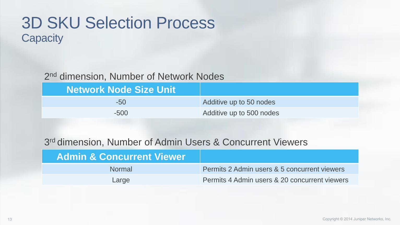
3D SKU Selection ProcessCapacity
Network Node Size Unit
-50 Additive up to 50 nodes
-500 Additive up to 500 nodes
Admin & Concurrent Viewer
Normal Permits 2 Admin users & 5 concurrent viewers
Large Permits 4 Admin users & 20 concurrent viewers
2nd dimension, Number of Network Nodes
3rd dimension, Number of Admin Users & Concurrent Viewers

WANDL IP/MPLS ViewUse Case Scenarios
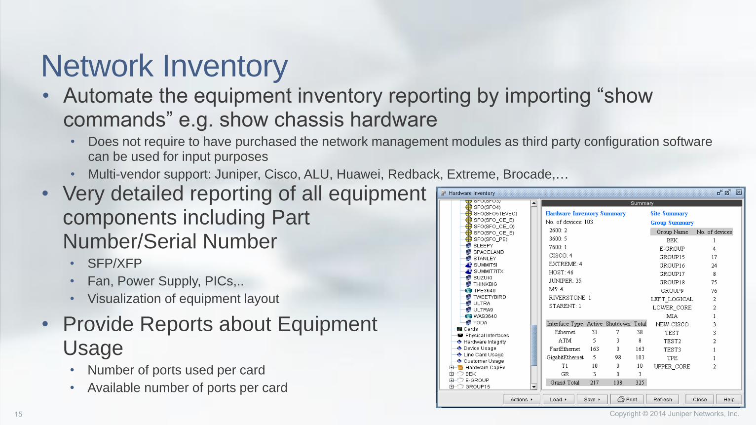
Network Inventory• Automate the equipment inventory reporting by importing “show
commands” e.g. show chassis hardware• Does not require to have purchased the network management modules as third party configuration software
can be used for input purposes
• Multi-vendor support: Juniper, Cisco, ALU, Huawei, Redback, Extreme, Brocade,…
• Very detailed reporting of all equipment components including Part Number/Serial Number• SFP/XFP
• Fan, Power Supply, PICs,..
• Visualization of equipment layout
• Provide Reports about Equipment Usage• Number of ports used per card
• Available number of ports per card
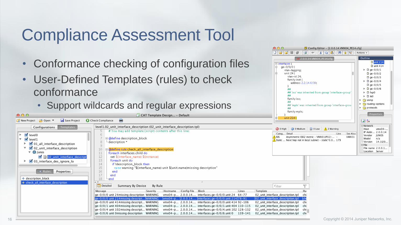
Compliance Assessment Tool
• Conformance checking of configuration files
• User-Defined Templates (rules) to check conformance• Support wildcards and regular expressions
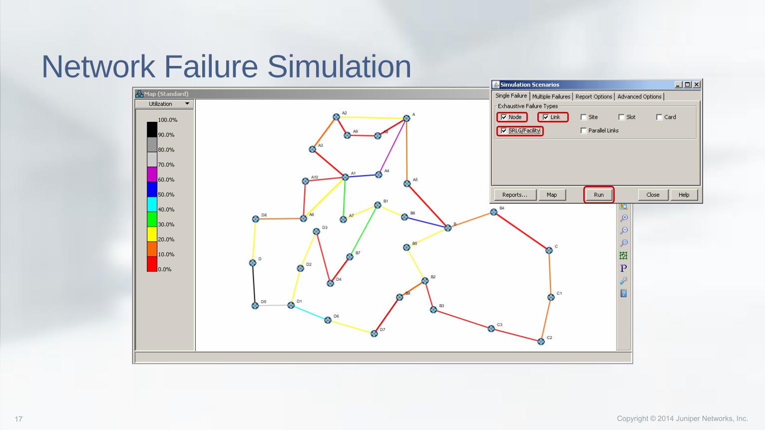
Network Failure Simulation
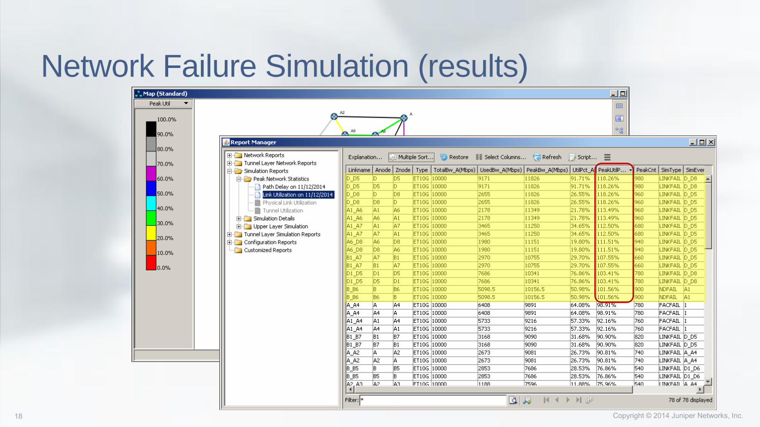
Network Failure Simulation (results)
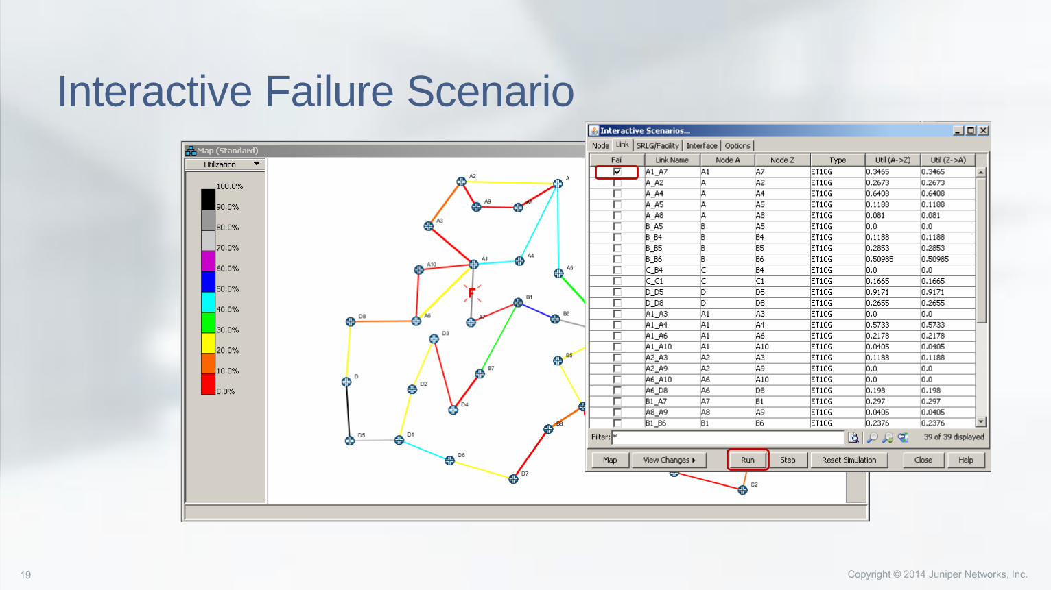
Interactive Failure Scenario
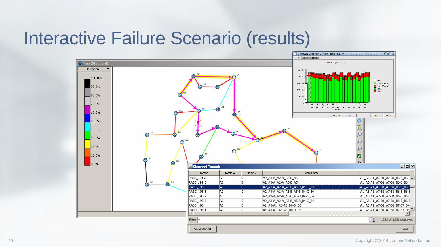
Interactive Failure Scenario (results)
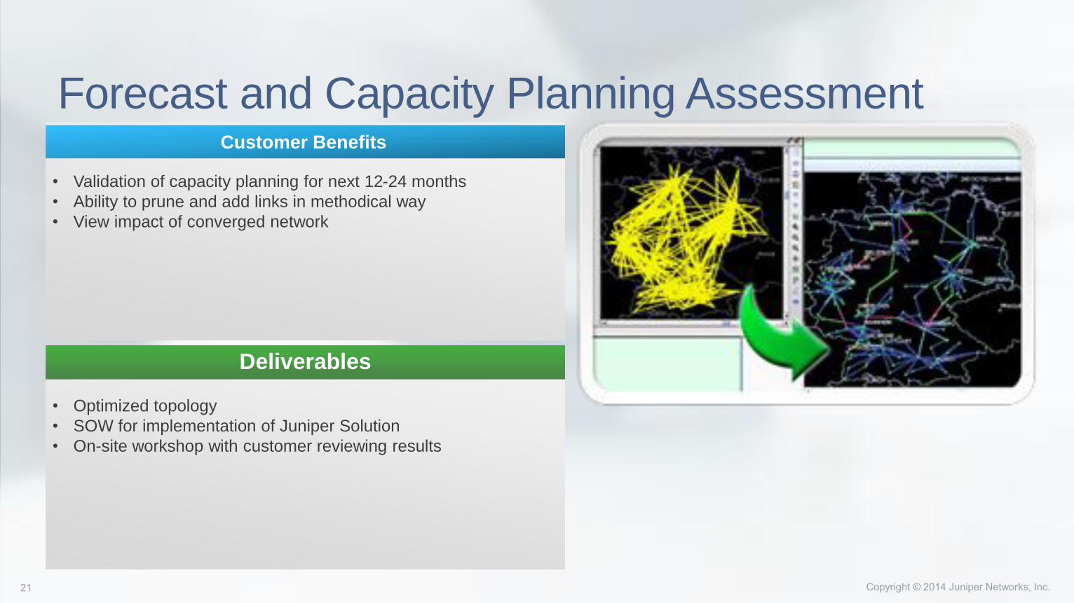
Forecast and Capacity Planning Assessment
• Validation of capacity planning for next 12-24 months
• Ability to prune and add links in methodical way
• View impact of converged network
Customer Benefits
• Optimized topology
• SOW for implementation of Juniper Solution
• On-site workshop with customer reviewing results
Deliverables
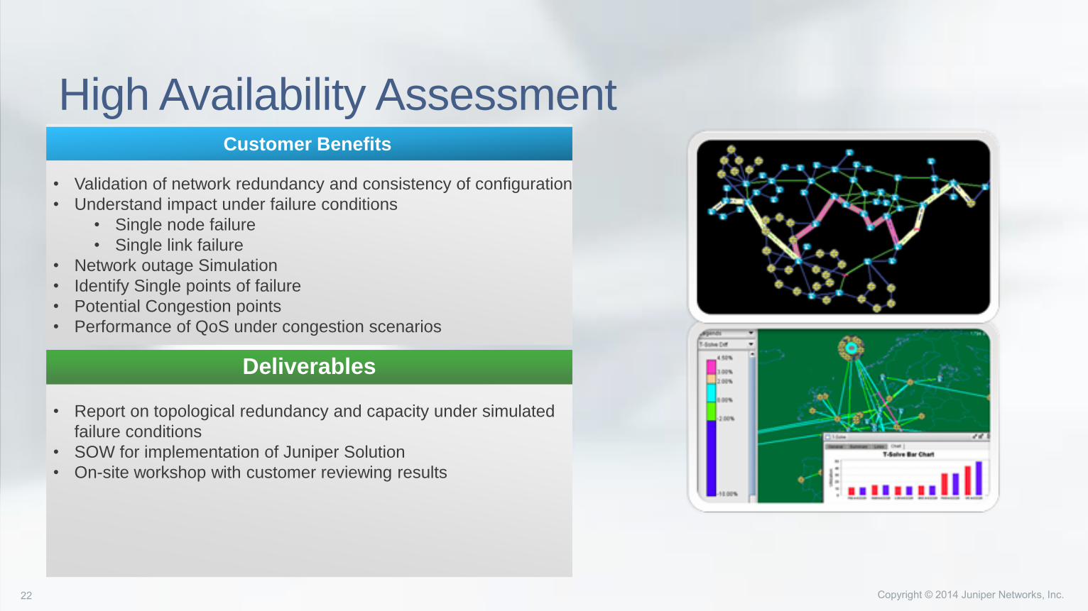
High Availability Assessment
• Validation of network redundancy and consistency of configuration
• Understand impact under failure conditions
• Single node failure
• Single link failure
• Network outage Simulation
• Identify Single points of failure
• Potential Congestion points
• Performance of QoS under congestion scenarios
Customer Benefits
• Report on topological redundancy and capacity under simulated
failure conditions
• SOW for implementation of Juniper Solution
• On-site workshop with customer reviewing results
Deliverables

NorthStar
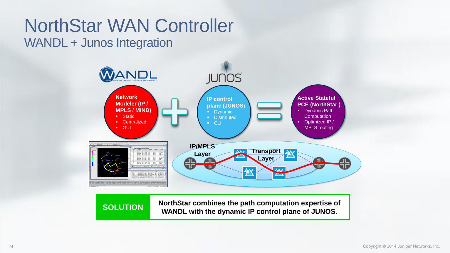
NorthStar WAN ControllerWANDL + Junos Integration
IP/MPLS
LayerTransport
Layer
SOLUTIONNorthStar combines the path computation expertise of
WANDL with the dynamic IP control plane of JUNOS.
Network
Modeler (IP /
MPLS / MIND) Static
Centralized
GUI
IP control
plane (JUNOS) Dynamic
Distributed
CLI
Active Stateful
PCE (NorthStar ) Dynamic Path
Computation
Optimized IP /
MPLS routing
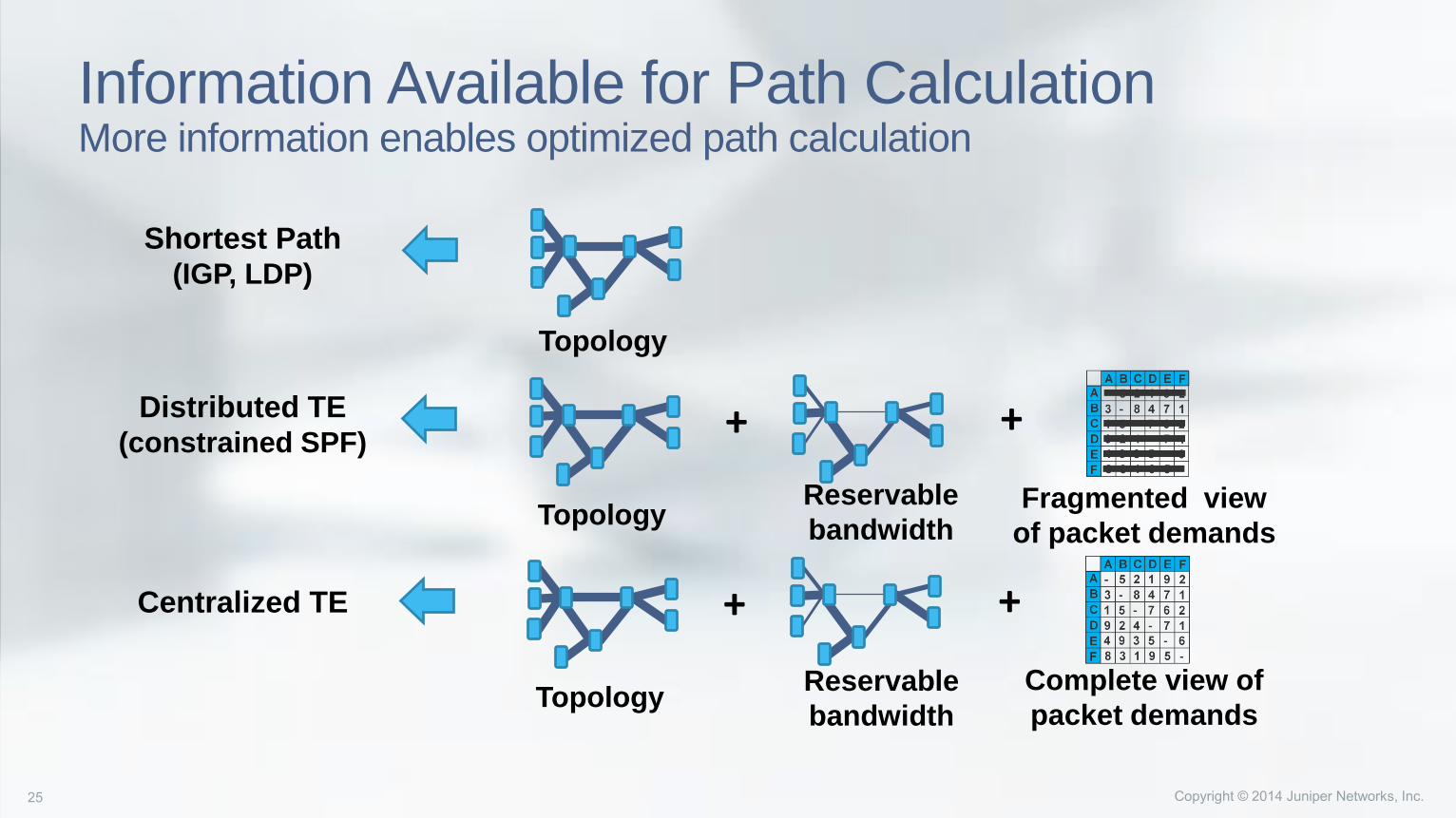
Information Available for Path CalculationMore information enables optimized path calculation
Shortest Path(IGP, LDP)
Distributed TE(constrained SPF)
+
Reservable
bandwidthTopology
+
Centralized TE +
Reservable
bandwidthTopology
+
Complete view of
packet demands
Fragmented view
of packet demands
Topology
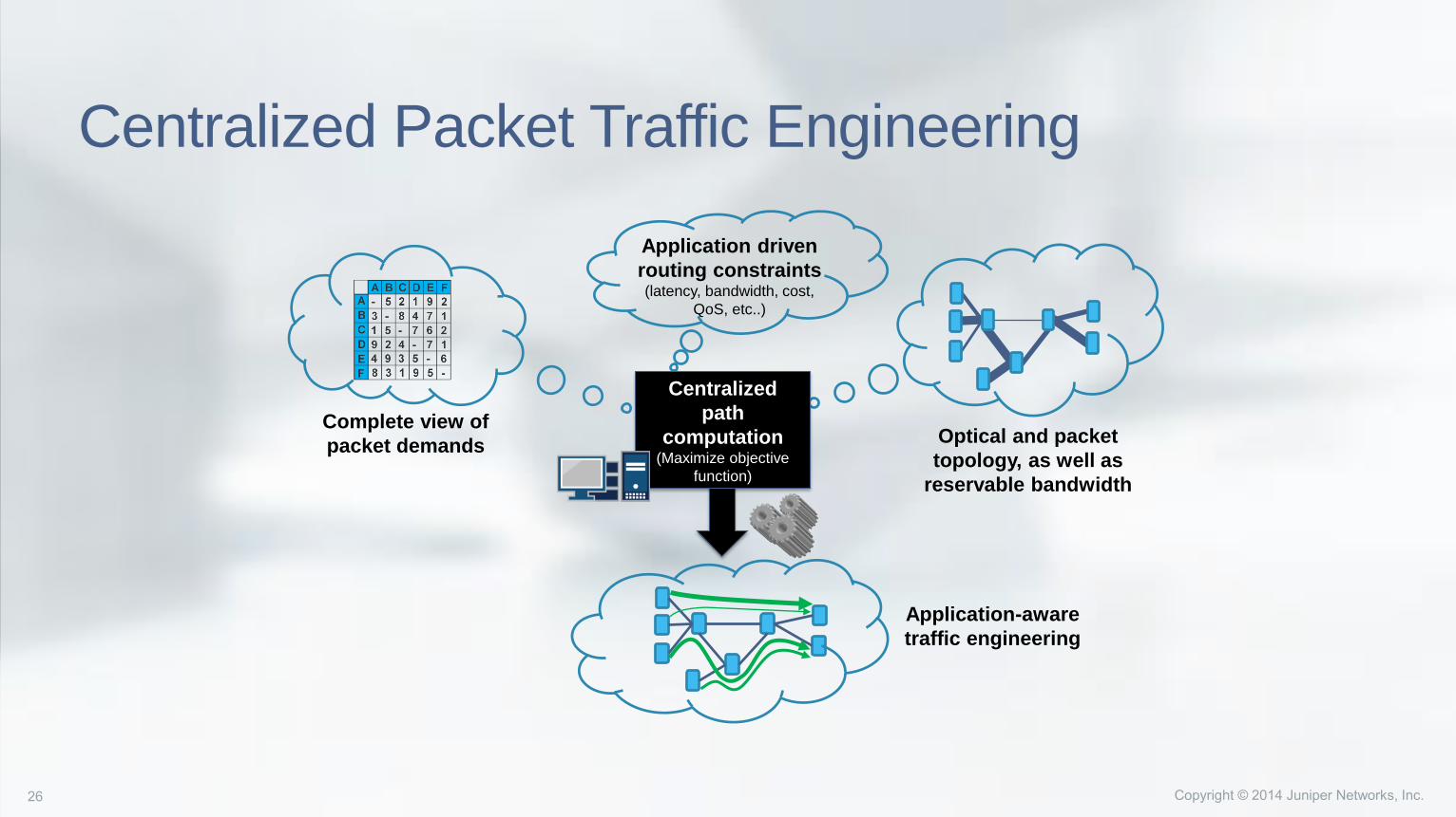
Centralized Packet Traffic Engineering
Application driven
routing constraints (latency, bandwidth, cost,
QoS, etc..)
Optical and packet
topology, as well as
reservable bandwidth
Centralized
path
computation(Maximize objective
function)
Complete view of
packet demands
Application-aware
traffic engineering
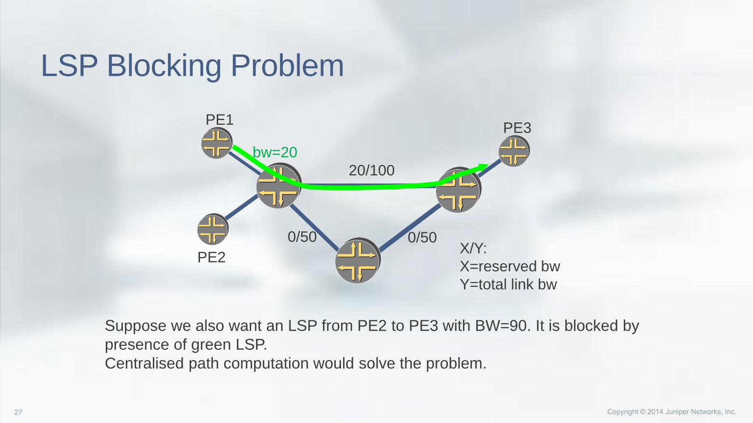
LSP Blocking Problem
20/100
0/50 0/50
PE1
PE2
PE3
X/Y:
X=reserved bw
Y=total link bw
Suppose we also want an LSP from PE2 to PE3 with BW=90. It is blocked by
presence of green LSP.
Centralised path computation would solve the problem.
bw=20
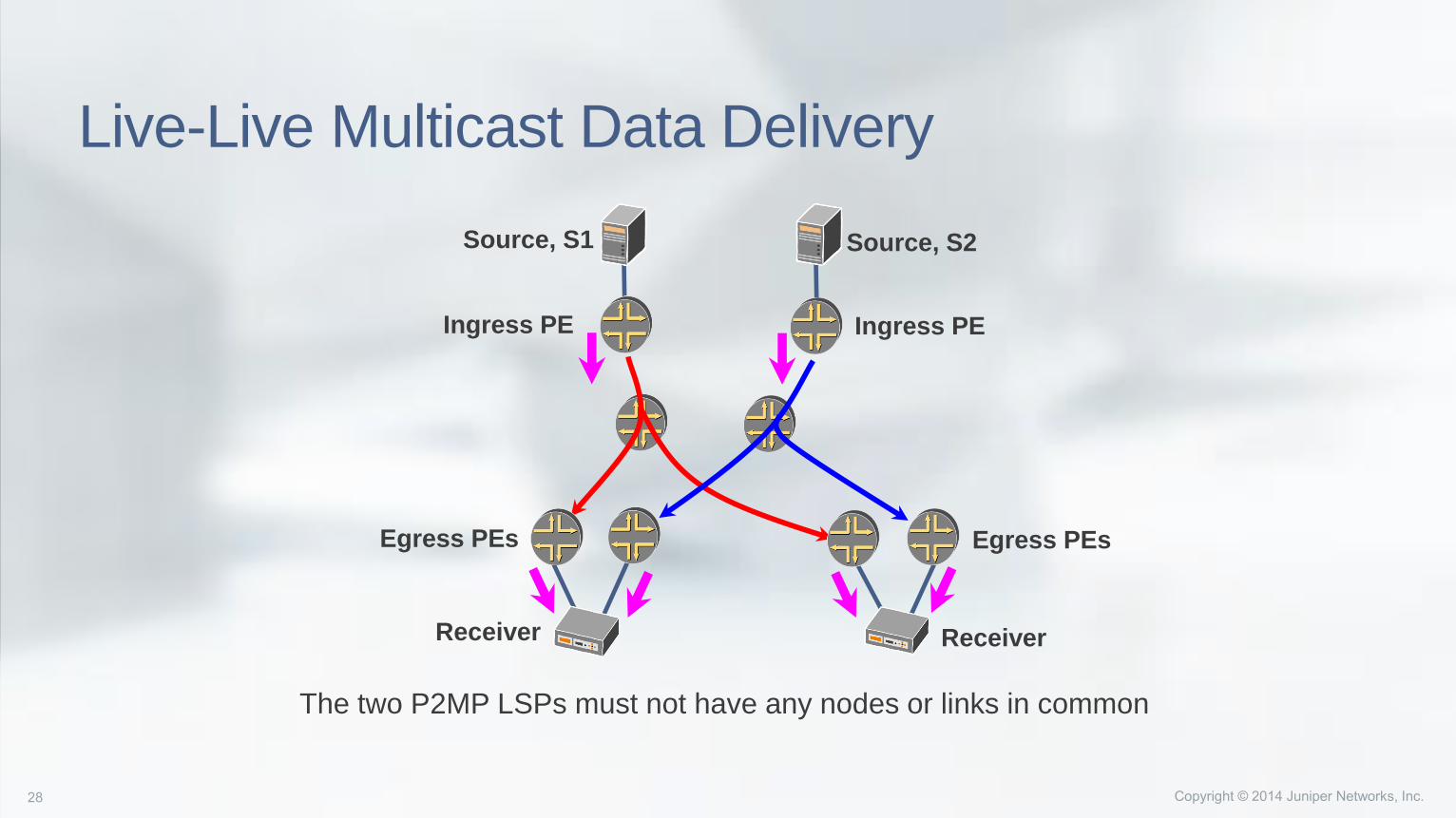
Live-Live Multicast Data Delivery
Source, S1 Source, S2
Ingress PE Ingress PE
Egress PEsEgress PEs
ReceiverReceiver
The two P2MP LSPs must not have any nodes or links in common
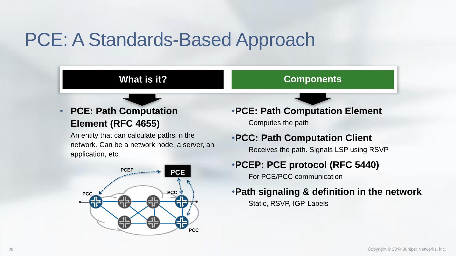
PCE: A Standards-Based Approach
• PCE: Path Computation
Element (RFC 4655)An entity that can calculate paths in the
network. Can be a network node, a server, an
application, etc.
•PCE: Path Computation ElementComputes the path
•PCC: Path Computation Client Receives the path. Signals LSP using RSVP
•PCEP: PCE protocol (RFC 5440)For PCE/PCC communication
•Path signaling & definition in the networkStatic, RSVP, IGP-Labels
ComponentsWhat is it?
PCEPCEP
PCC PCC
PCC
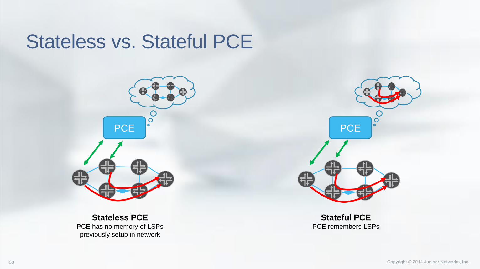
Stateless vs. Stateful PCE
PCE
Stateless PCEPCE has no memory of LSPs
previously setup in network
PCE
Stateful PCEPCE remembers LSPs
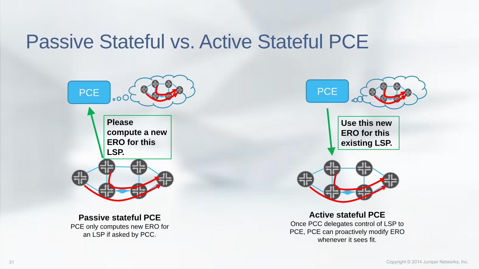
Passive Stateful vs. Active Stateful PCE
PCE
Passive stateful PCEPCE only computes new ERO for
an LSP if asked by PCC.
PCE
Active stateful PCEOnce PCC delegates control of LSP to
PCE, PCE can proactively modify ERO
whenever it sees fit.
Please
compute a new
ERO for this
LSP.
Use this new
ERO for this
existing LSP.
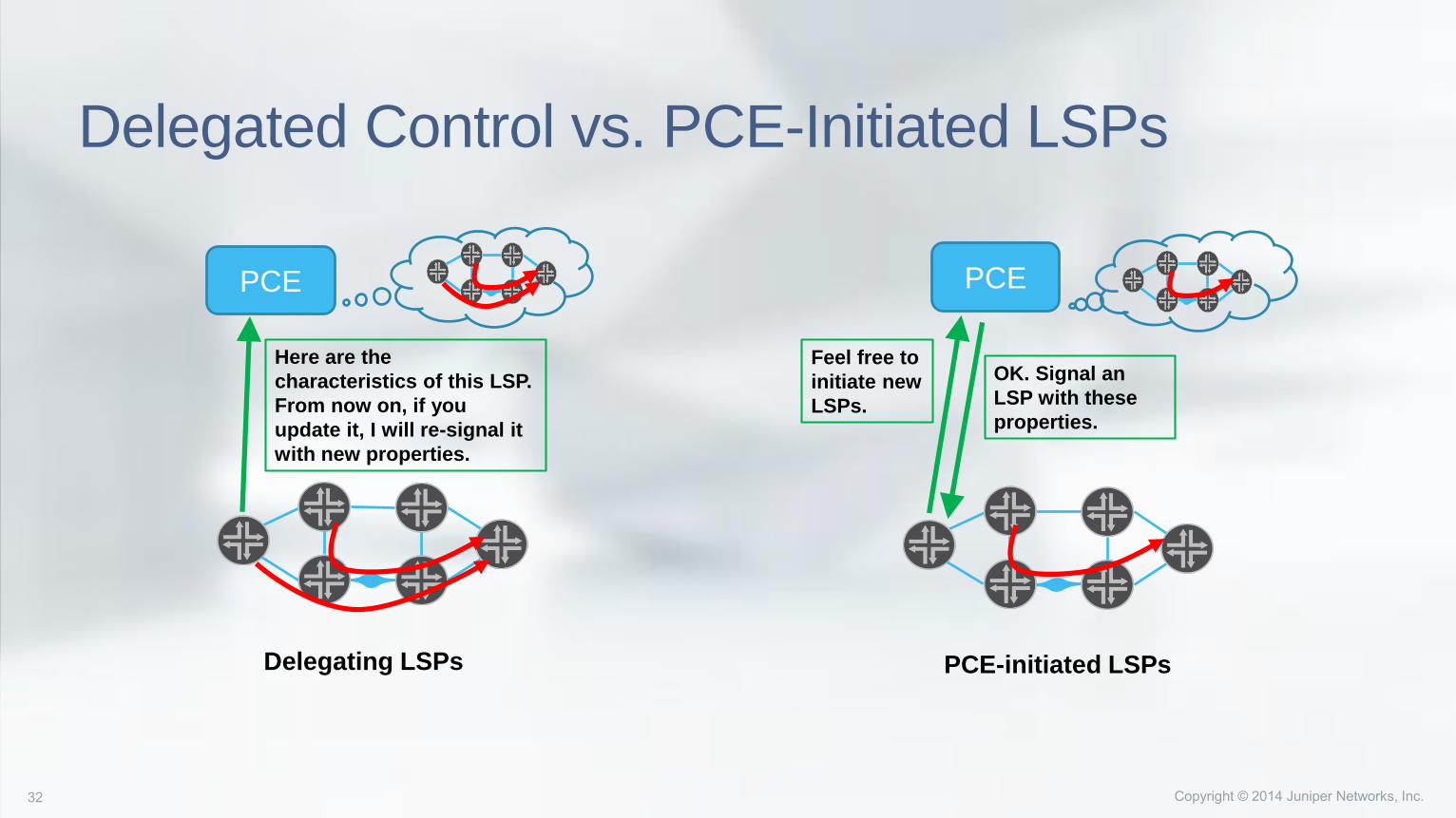
Delegated Control vs. PCE-Initiated LSPs
PCE
Delegating LSPs
PCE
PCE-initiated LSPs
Here are the
characteristics of this LSP.
From now on, if you
update it, I will re-signal it
with new properties.
Feel free to
initiate new
LSPs.
OK. Signal an
LSP with these
properties.
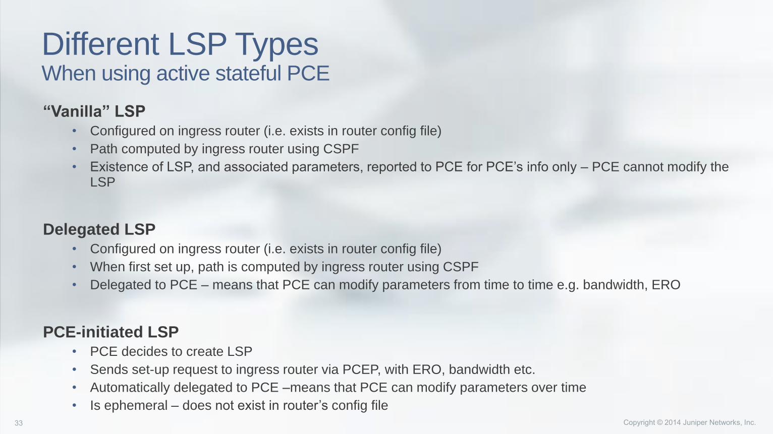
Different LSP TypesWhen using active stateful PCE
“Vanilla” LSP• Configured on ingress router (i.e. exists in router config file)
• Path computed by ingress router using CSPF
• Existence of LSP, and associated parameters, reported to PCE for PCE’s info only – PCE cannot modify the LSP
Delegated LSP• Configured on ingress router (i.e. exists in router config file)
• When first set up, path is computed by ingress router using CSPF
• Delegated to PCE – means that PCE can modify parameters from time to time e.g. bandwidth, ERO
PCE-initiated LSP• PCE decides to create LSP
• Sends set-up request to ingress router via PCEP, with ERO, bandwidth etc.
• Automatically delegated to PCE –means that PCE can modify parameters over time
• Is ephemeral – does not exist in router’s config file
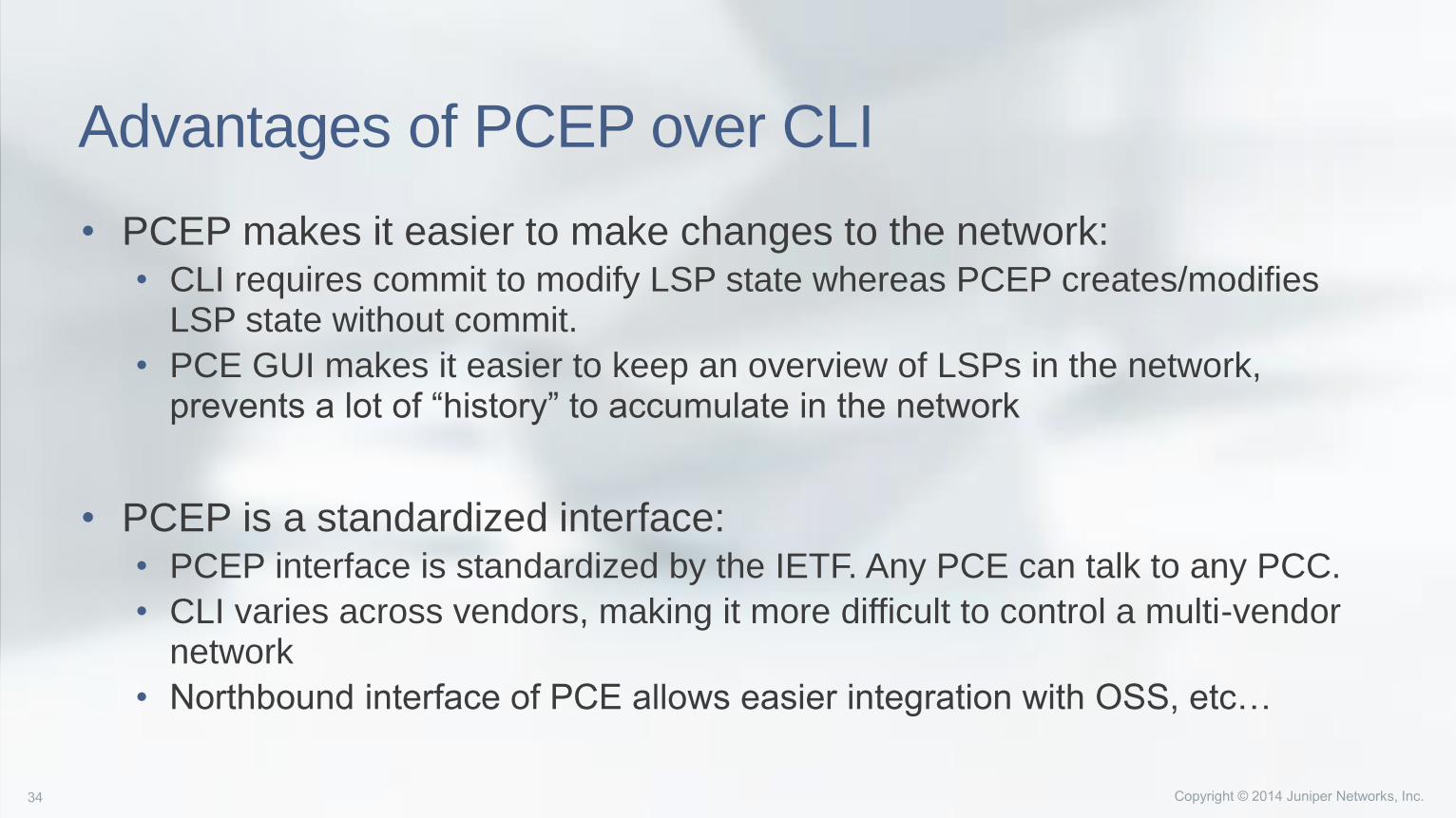
Advantages of PCEP over CLI
• PCEP makes it easier to make changes to the network:• CLI requires commit to modify LSP state whereas PCEP creates/modifies
LSP state without commit.
• PCE GUI makes it easier to keep an overview of LSPs in the network, prevents a lot of “history” to accumulate in the network
• PCEP is a standardized interface:• PCEP interface is standardized by the IETF. Any PCE can talk to any PCC.
• CLI varies across vendors, making it more difficult to control a multi-vendor network
• Northbound interface of PCE allows easier integration with OSS, etc…
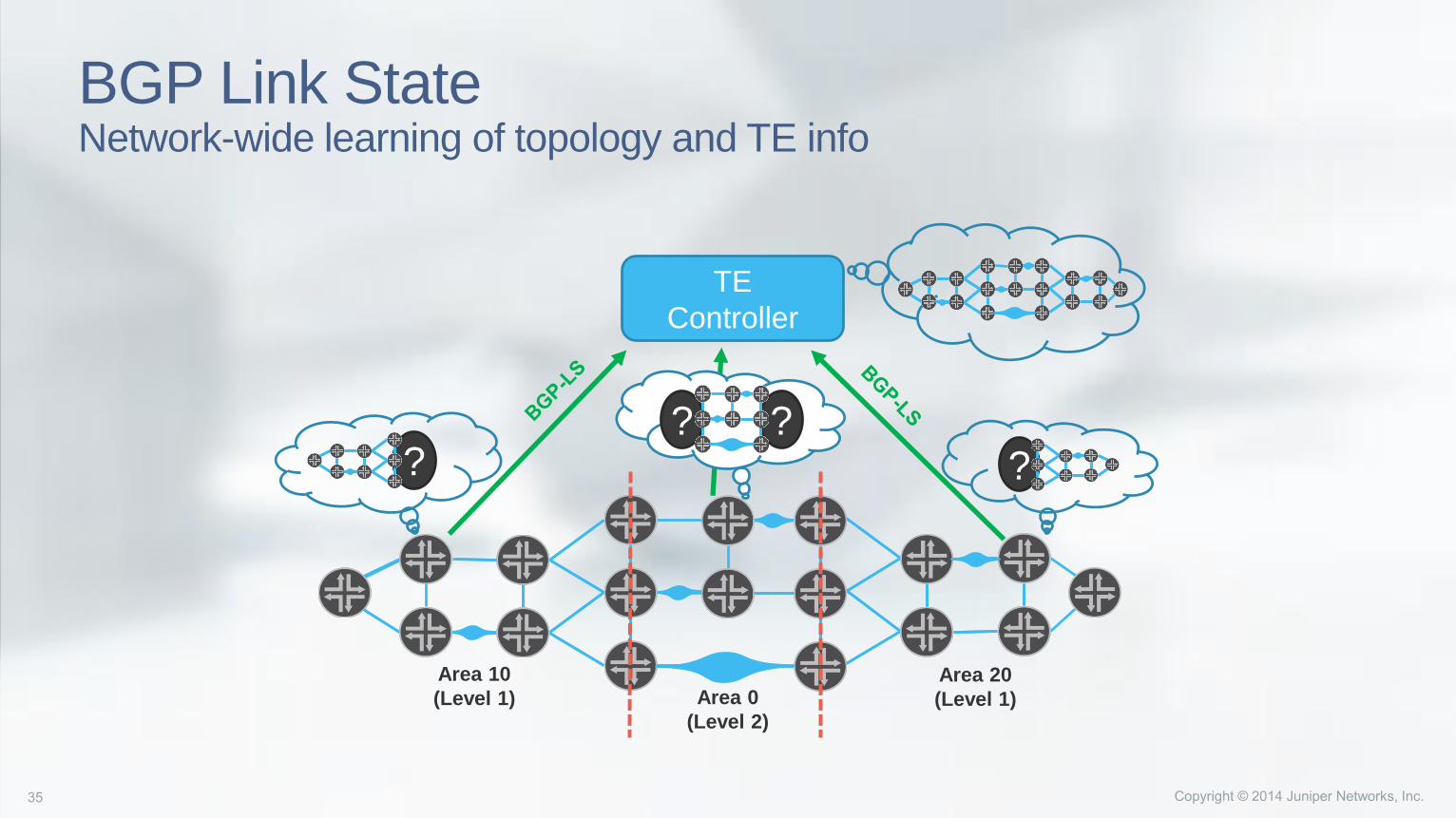
BGP Link StateNetwork-wide learning of topology and TE info
??
Area 0
(Level 2)
Area 20
(Level 1)
Area 10
(Level 1)
? ?
TE
Controller
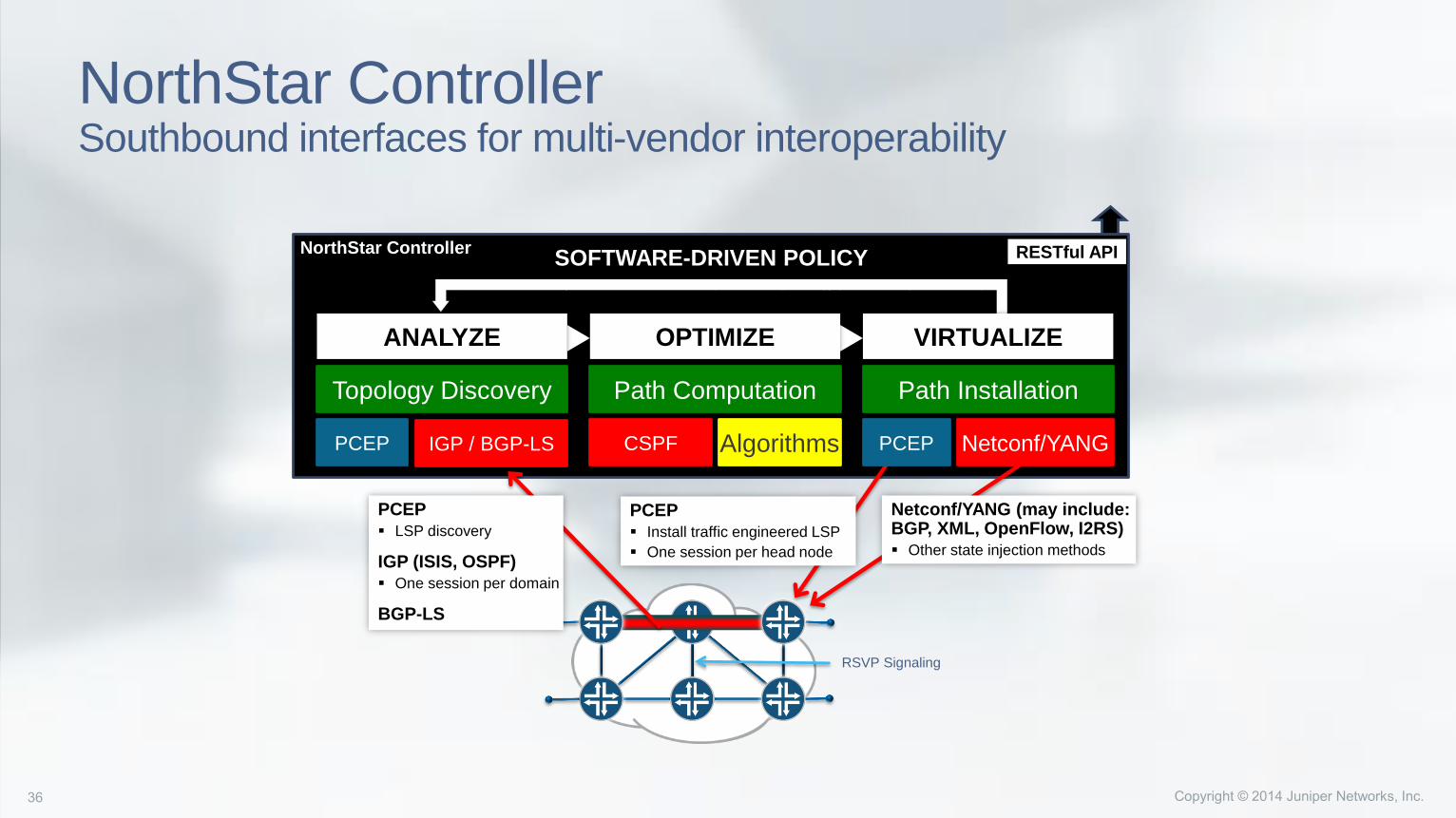
NorthStar ControllerSouthbound interfaces for multi-vendor interoperability
SOFTWARE-DRIVEN POLICY
Topology Discovery Path Computation Path Installation
PCEP Install traffic engineered LSP
One session per head node
Netconf/YANG (may include: BGP, XML, OpenFlow, I2RS) Other state injection methods
ANALYZE OPTIMIZE VIRTUALIZE
PCEP Netconf/YANGPCEPCSPF Algorithms
RSVP Signaling
RESTful APINorthStar Controller
IGP / BGP-LS
PCEP LSP discovery
IGP (ISIS, OSPF) One session per domain
BGP-LS
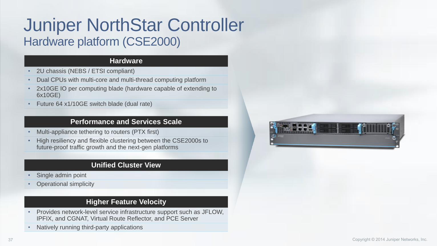
Juniper NorthStar ControllerHardware platform (CSE2000)
Hardware
• 2U chassis (NEBS / ETSI compliant)
• Dual CPUs with multi-core and multi-thread computing platform
• 2x10GE IO per computing blade (hardware capable of extending to 6x10GE)
• Future 64 x1/10GE switch blade (dual rate)
Performance and Services Scale
• Multi-appliance tethering to routers (PTX first)
• High resiliency and flexible clustering between the CSE2000s to future-proof traffic growth and the next-gen platforms
Unified Cluster View
• Single admin point
• Operational simplicity
Higher Feature Velocity
• Provides network-level service infrastructure support such as JFLOW, IPFIX, and CGNAT, Virtual Route Reflector, and PCE Server
• Natively running third-party applications
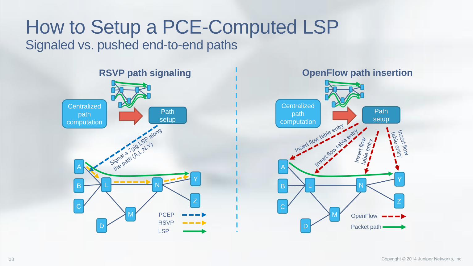
How to Setup a PCE-Computed LSPSignaled vs. pushed end-to-end paths
NL
A
M
BY
C
D
Z
PCEP
RSVP
LSP
NL
A
M
BY
C
D
Z
OpenFlow
Packet path
Path
setup
Centralized
path
computation
Path
setup
Centralized
path
computation
RSVP path signaling OpenFlow path insertion
Why Use PCE for Network Programmability?
PCE allows an evolutionary approach towards centralized control of network
infrastructure:
• No need to replace entire control and forwarding infrastructure (as with Openflow) - only the
edge nodes need to support PCEP
• Can continue to use the same protocols for signaling (RSVP-TE) and same schemes for
mapping traffic to paths at the edges
• Only needs a SW upgrade to enable the client functionality
• Local repair capability in case of network failures using the distributed control plane and with
established protocols, this is difficult with a fully centralized approach
• Can easily work in a hybrid architecture where part of the traffic is managed via a central
controller and part of the traffic uses the conventional distributed approach
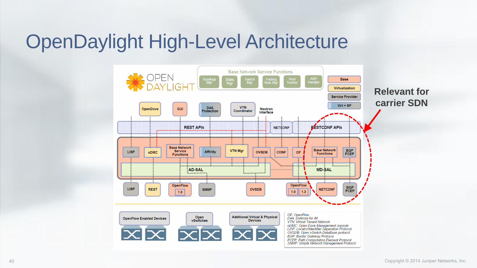
OpenDaylight High-Level Architecture
Relevant for
carrier SDN

NorthStarUse Case Scenarios
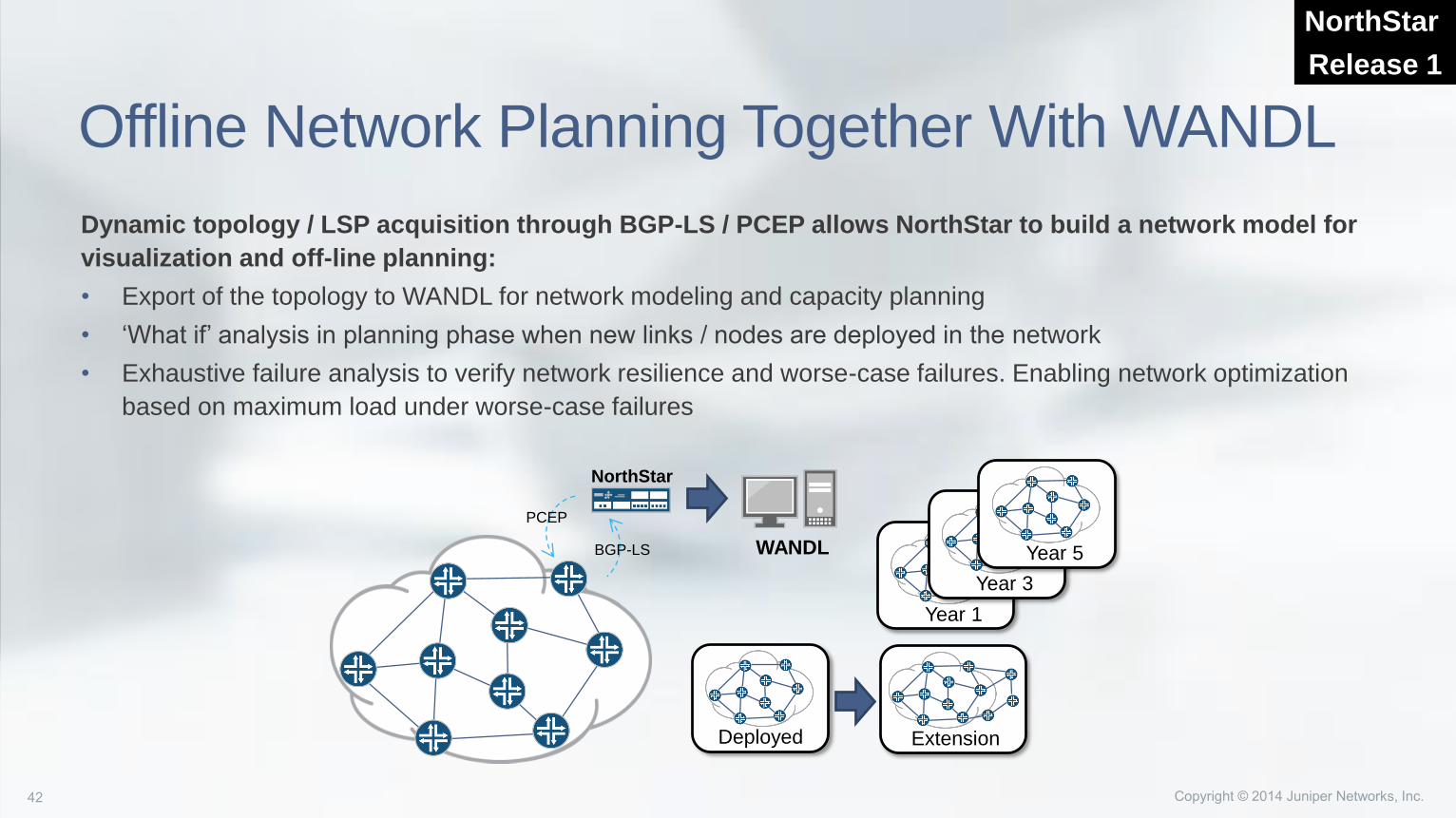
Offline Network Planning Together With WANDL
Dynamic topology / LSP acquisition through BGP-LS / PCEP allows NorthStar to build a network model for
visualization and off-line planning:
• Export of the topology to WANDL for network modeling and capacity planning
• ‘What if’ analysis in planning phase when new links / nodes are deployed in the network
• Exhaustive failure analysis to verify network resilience and worse-case failures. Enabling network optimization
based on maximum load under worse-case failures
NorthStar
Release 1
Year 1
Year 3
Year 5
Deployed Extension
WANDL
NorthStar
PCEP
BGP-LS
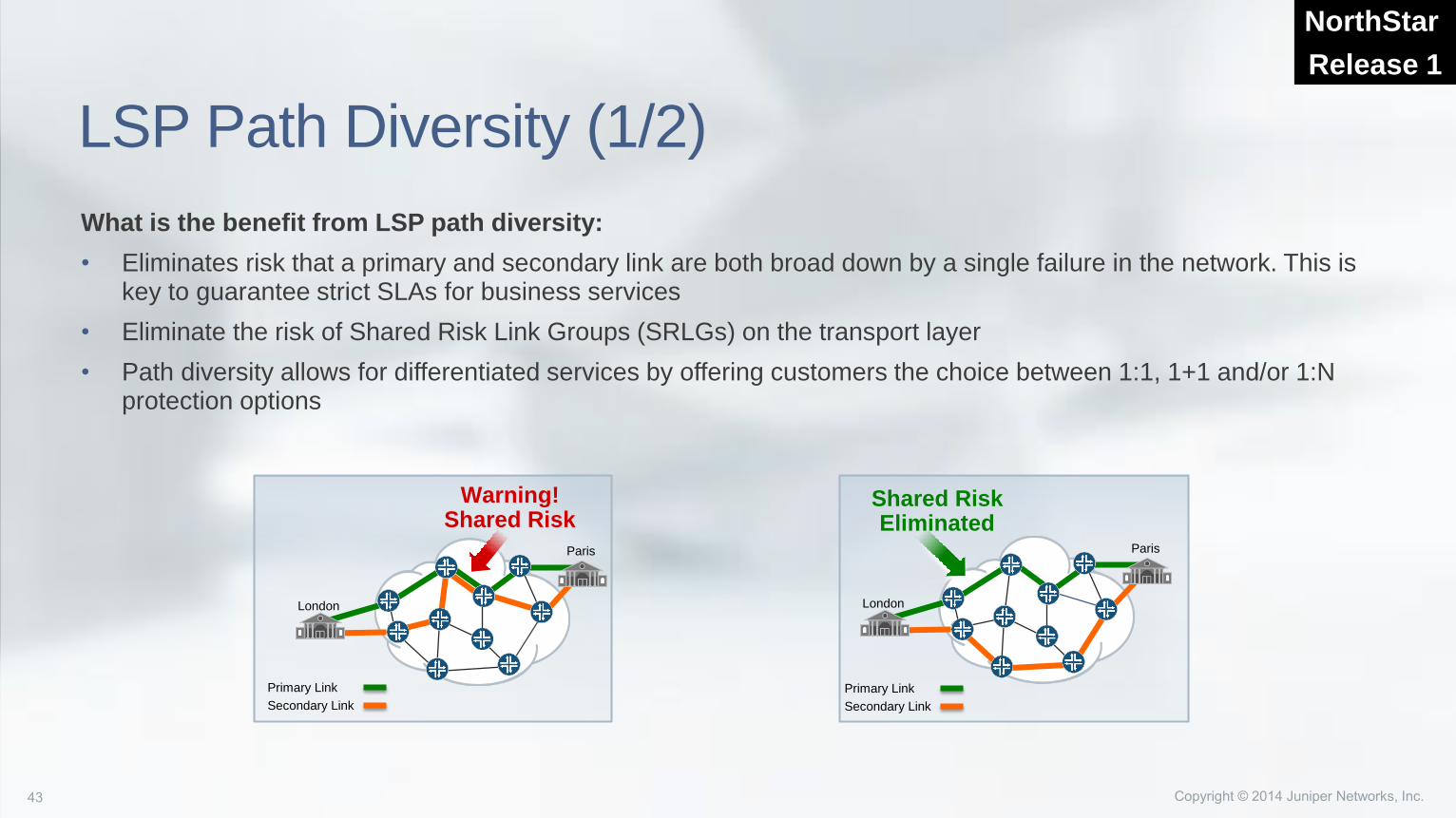
LSP Path Diversity (1/2)
What is the benefit from LSP path diversity:
• Eliminates risk that a primary and secondary link are both broad down by a single failure in the network. This is key to guarantee strict SLAs for business services
• Eliminate the risk of Shared Risk Link Groups (SRLGs) on the transport layer
• Path diversity allows for differentiated services by offering customers the choice between 1:1, 1+1 and/or 1:N protection options
London
Paris
Warning!Shared Risk
Shared RiskEliminated
Primary Link
Secondary Link
Primary Link
Secondary Link
London
Paris
NorthStar
Release 1
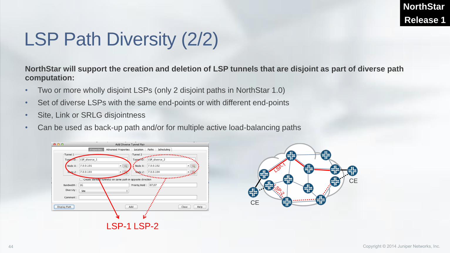
LSP Path Diversity (2/2)
NorthStar will support the creation and deletion of LSP tunnels that are disjoint as part of diverse path computation:
• Two or more wholly disjoint LSPs (only 2 disjoint paths in NorthStar 1.0)
• Set of diverse LSPs with the same end-points or with different end-points
• Site, Link or SRLG disjointness
• Can be used as back-up path and/or for multiple active load-balancing paths
NorthStar
Release 1
CE
CE
LSP-1 LSP-2
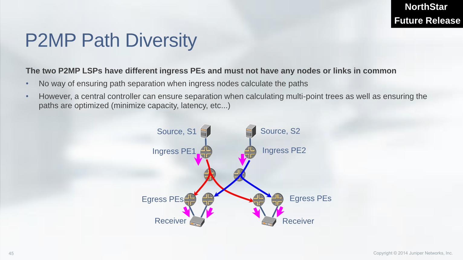
P2MP Path Diversity
The two P2MP LSPs have different ingress PEs and must not have any nodes or links in common
• No way of ensuring path separation when ingress nodes calculate the paths
• However, a central controller can ensure separation when calculating multi-point trees as well as ensuring the paths are optimized (minimize capacity, latency, etc...)
NorthStar
Future Release
Source, S1 Source, S2
Ingress PE1 Ingress PE2
Egress PEsEgress PEs
ReceiverReceiver
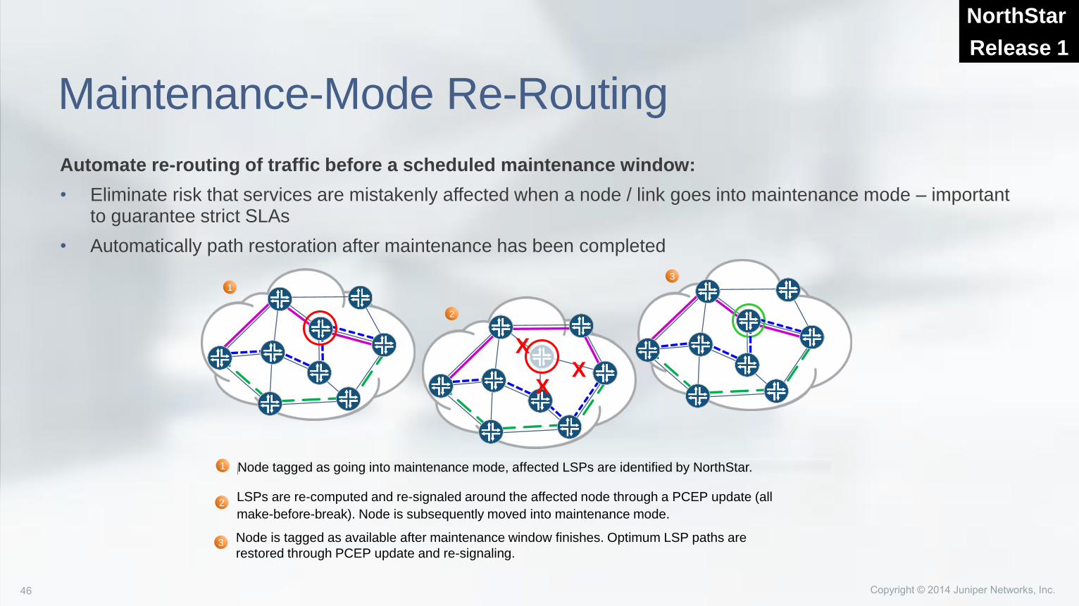
Maintenance-Mode Re-Routing
Automate re-routing of traffic before a scheduled maintenance window:
• Eliminate risk that services are mistakenly affected when a node / link goes into maintenance mode – important to guarantee strict SLAs
• Automatically path restoration after maintenance has been completed
NorthStar
Release 1
Node tagged as going into maintenance mode, affected LSPs are identified by NorthStar.1
1
3
XX
X
2
2LSPs are re-computed and re-signaled around the affected node through a PCEP update (all
make-before-break). Node is subsequently moved into maintenance mode.
3 Node is tagged as available after maintenance window finishes. Optimum LSP paths are
restored through PCEP update and re-signaling.
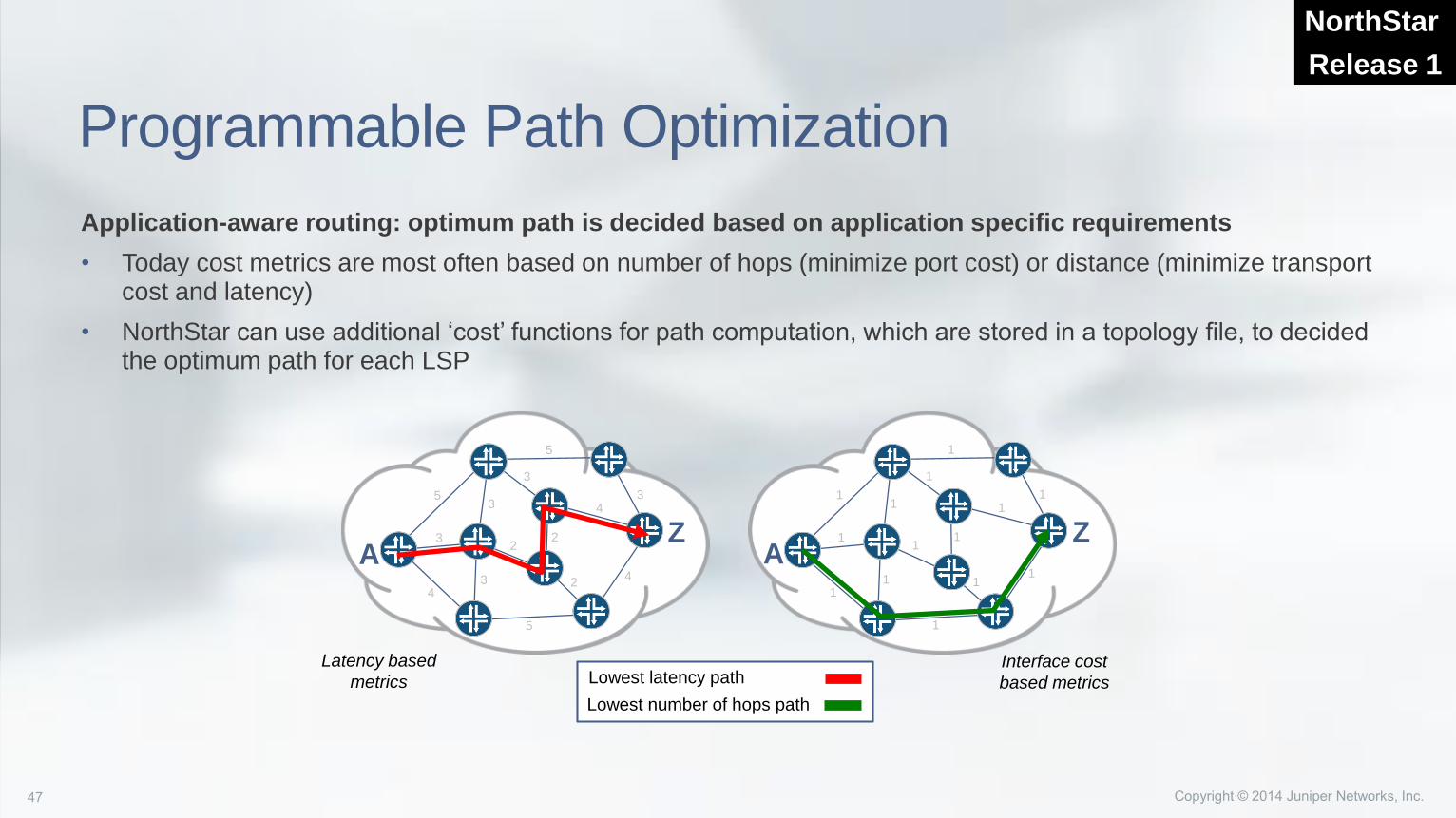
Programmable Path Optimization
Application-aware routing: optimum path is decided based on application specific requirements
• Today cost metrics are most often based on number of hops (minimize port cost) or distance (minimize transport cost and latency)
• NorthStar can use additional ‘cost’ functions for path computation, which are stored in a topology file, to decided the optimum path for each LSP
NorthStar
Release 1
Lowest latency path
Lowest number of hops path
Latency based
metricsInterface cost
based metrics
5
5 3
2
32
2
3
4
3
4
3 4
5
AZ
1
1 1
1
1
1
11
1
1
1
1
1
1
ZA
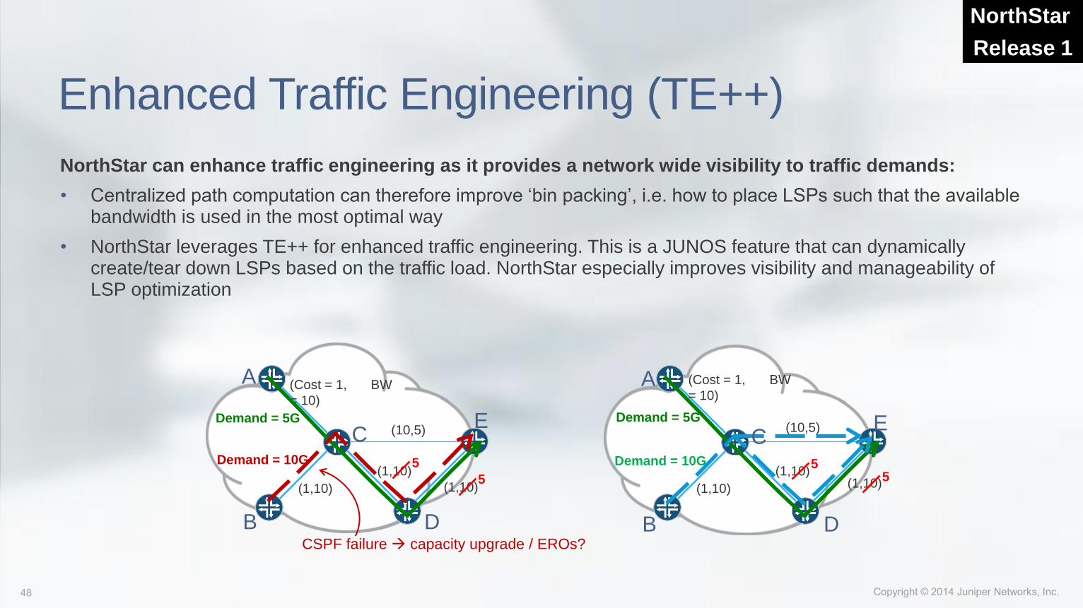
Enhanced Traffic Engineering (TE++)
NorthStar can enhance traffic engineering as it provides a network wide visibility to traffic demands:
• Centralized path computation can therefore improve ‘bin packing’, i.e. how to place LSPs such that the available bandwidth is used in the most optimal way
• NorthStar leverages TE++ for enhanced traffic engineering. This is a JUNOS feature that can dynamically create/tear down LSPs based on the traffic load. NorthStar especially improves visibility and manageability of LSP optimization
NorthStar
Release 1
(Cost = 1, BW
= 10)
(1,10)
(1,10)
(1,10)
(10,5)Demand = 5G
Demand = 10G
CSPF failure capacity upgrade / EROs?
(Cost = 1, BW
= 10)
(1,10)
(1,10)(1,10)
(10,5)
5
5
Demand = 5G
Demand = 10G 55
A
B
C
D
E
A
B
C
D
E
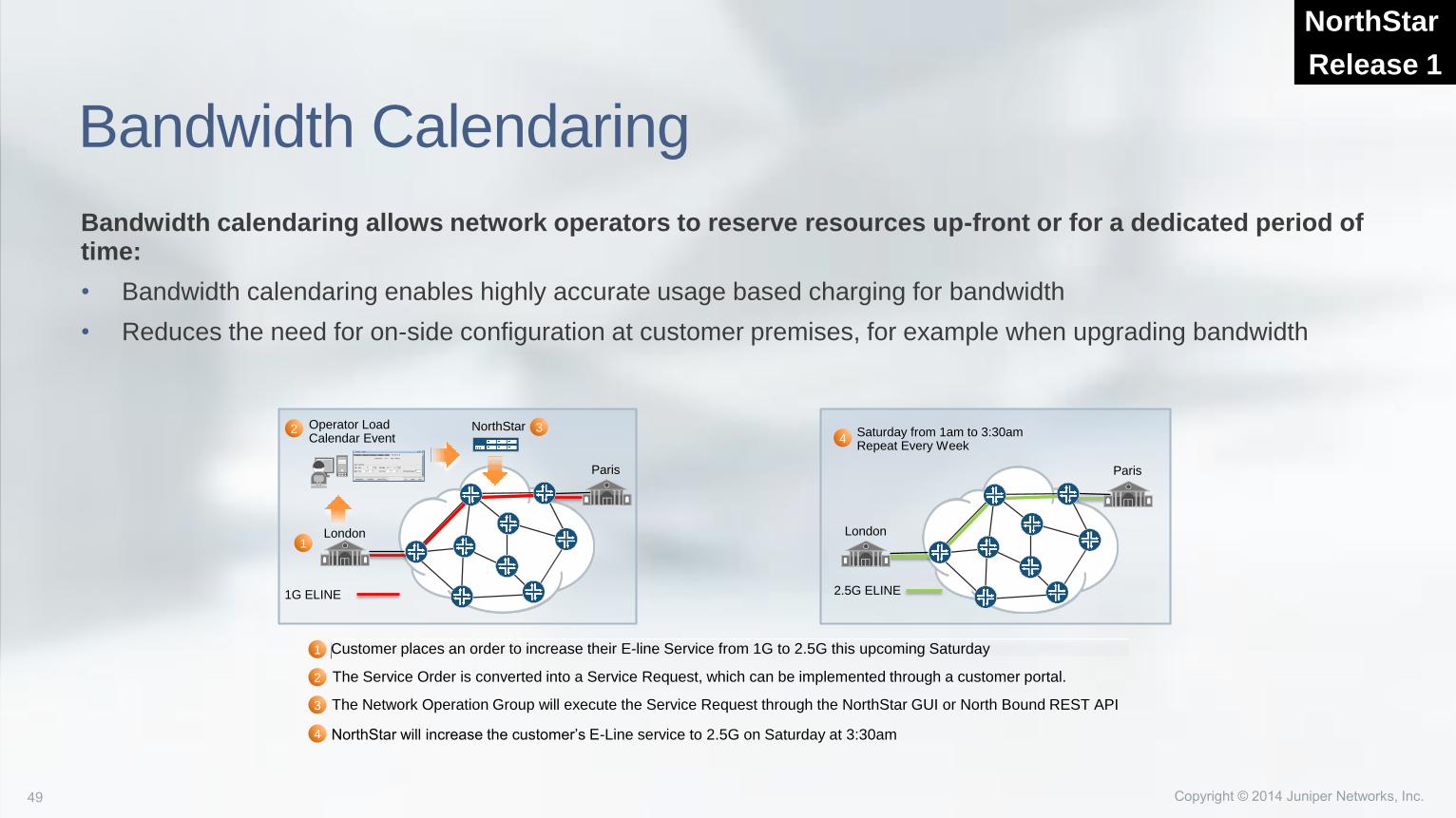
Bandwidth Calendaring
Bandwidth calendaring allows network operators to reserve resources up-front or for a dedicated period of time:
• Bandwidth calendaring enables highly accurate usage based charging for bandwidth
• Reduces the need for on-side configuration at customer premises, for example when upgrading bandwidth
NorthStar
Release 1
London
2.5G ELINE
Paris
London
1G ELINE
NorthStar 3 Saturday from 1am to 3:30amRepeat Every Week
4
1
Operator Load Calendar Event
2
Paris
Customer places an order to increase their E-line Service from 1G to 2.5G this upcoming Saturday1
3 The Network Operation Group will execute the Service Request through the NorthStar GUI or North Bound REST API
4 NorthStar will increase the customer’s E-Line service to 2.5G on Saturday at 3:30am
2 The Service Order is converted into a Service Request, which can be implemented through a customer portal.
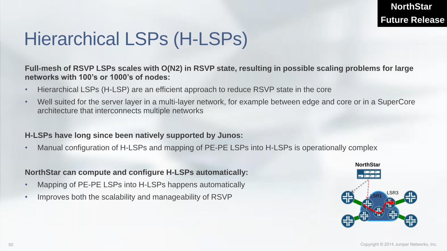
Hierarchical LSPs (H-LSPs)
Full-mesh of RSVP LSPs scales with O(N2) in RSVP state, resulting in possible scaling problems for large networks with 100’s or 1000’s of nodes:
• Hierarchical LSPs (H-LSP) are an efficient approach to reduce RSVP state in the core
• Well suited for the server layer in a multi-layer network, for example between edge and core or in a SuperCorearchitecture that interconnects multiple networks
H-LSPs have long since been natively supported by Junos:
• Manual configuration of H-LSPs and mapping of PE-PE LSPs into H-LSPs is operationally complex
NorthStar can compute and configure H-LSPs automatically:
• Mapping of PE-PE LSPs into H-LSPs happens automatically
• Improves both the scalability and manageability of RSVP
NorthStar
Future Release
NorthStar
LSR1LSR3
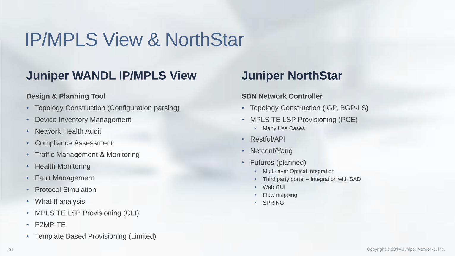
Design & Planning Tool
• Topology Construction (Configuration parsing)
• Device Inventory Management
• Network Health Audit
• Compliance Assessment
• Traffic Management & Monitoring
• Health Monitoring
• Fault Management
• Protocol Simulation
• What If analysis
• MPLS TE LSP Provisioning (CLI)
• P2MP-TE
• Template Based Provisioning (Limited)
SDN Network Controller
• Topology Construction (IGP, BGP-LS)
• MPLS TE LSP Provisioning (PCE)• Many Use Cases
• Restful/API
• Netconf/Yang
• Futures (planned)• Multi-layer Optical Integration
• Third party portal – Integration with SAD
• Web GUI
• Flow mapping
• SPRING
Juniper WANDL IP/MPLS View Juniper NorthStar
IP/MPLS View & NorthStar

Спасибо