Embed Size (px)
Citation preview

Experiment - Interfacing Arduino With LED
Requirements – LED, Breadboard, Jumper Wires, Arduino, Resistence (1K)
Background – LED has two pins, one is longer than the the other. The longer one
will be attached with output pin (in this case 13) of the Arduino board and shorter
pin will be connected to ground through some resistence. If the lengths of both the
pins are equal then the pin with the small flag will be the output and other will be
for ground. The connection is made using jumper wires.
Fig – 2 LED Interfacing With Arduino
Code -
int led = 13; //initialize pin 13 on arduino as LED O/P
// the setup routine runs once when you press reset:
void setup() {
// initialize the digital pin as an output.
pinMode(led, OUTPUT);
}
// the loop routine runs over and over again forever:
void loop() {
digitalWrite(led, HIGH); // turn the LED on (HIGH is the voltage level)
delay(1000); // wait for a second
digitalWrite(led, LOW); // turn the LED off by making the voltage LOW
delay(1000); // wait for a second
}
Precautions –
1. Connections should be tight.
2. Do not put LED directly into Arduino board as it may get damaged
Result – LED turns on and off with a delay of 1 second.

Experiment - Controlling the intensity of LED Blinking and
Flashing using Potentiometer
Requirements – LED, Push Button, Jumper Wires, Resistence, Breadboard,
Arduino, Potentiometer
Background – Potentiometer has three terminals – Terminal 1, Wiper, and
Terminal 2. Terminal 1 is connected with 5V, Terminal 2 is connected with GND
and Wiper is connected with one of the analog pins (in this caseA0) fo input. On
rotating the potentiometer towards right the intensity and blinking will increase and
the scenario reverses when we tur the potentiometer towards left.
Fig – 3 Controlling LED Blinking and Flashing using Potentiometer

Code -
1. Intensity
const byte potentiometer = A0; //wiper connected to analog pin A0
const byte control = 13; //LED connected to pin 13
int reading; //to get readiing when potentiometer is rotating
int value; //to map the reading with particular range
void setup()
{
pinMode(control,OUTPUT);
Serial.begin(9600);
}
void loop()
{
reading = analogRead(potentiometer); //read value between 0 to 1023
value = map(reading,0,1023,0,255); //scale the value to use it with digital
pin(Servo)
analogWrite(control,value);
Serial.println(reading);
}

2. Flashing
int potpin = A0; // analog pin used to connect the potentiometer
int ledpin = 13;
int val; // variable to read the value from the analog pin
void setup()
{
pinMode(ledpin, OUTPUT);
}
void loop()
{
val = analogRead(potpin); // reads the value of the potentiometer (value between 0
and 1023)
val = map(val, 0, 1023, 500, 5); // scale it to use it with the servo (value between 0
and 180)
digitalWrite(ledpin, HIGH);
delay(val); // waits for the servo to get there
digitalWrite(ledpin, LOW);
delay(val);
}
Result – Controlling speed of blinking and intensity of LED is succesfull.

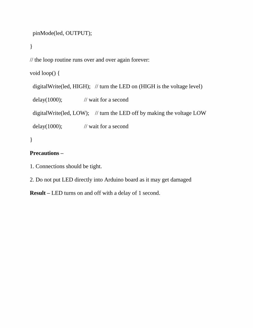
Experiment - Interfacing Arduino with DC Motor using L293D and
Controlling Speed
Requirements – DC Motor, Arduino Board, Breadboard, Jumper Wires, L293D
IC
Fig – 4 Interfacing and controlling speed of DC Motors
Code –
#define E1 10 // Enable Pin for motor 1
#define E2 11 // Enable Pin for motor 2
#define I1 8 // Control pin 1 for motor 1
#define I2 9 // Control pin 2 for motor 1
#define I3 12 // Control pin 1 for motor 2
#define I4 13 // Control pin 2 for motor 2
void setup() {
pinMode(E1, OUTPUT);
pinMode(E2, OUTPUT);
pinMode(I1, OUTPUT);
pinMode(I2, OUTPUT);
pinMode(I3, OUTPUT);
pinMode(I4, OUTPUT);
}
void loop() {
//FORWARD
analogWrite(E1, 255); // Run in full speed
analogWrite(E2, 25); // Run in full speed
digitalWrite(I1,HIGH);
digitalWrite(I2, LOW);
digitalWrite(I3, HIGH);
digitalWrite(I4, LOW);
delay(1000);
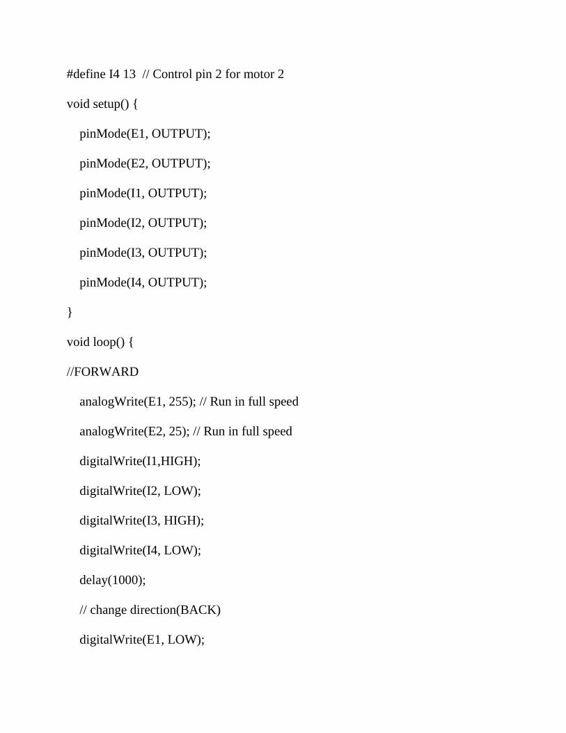
// change direction(BACK)
digitalWrite(E1, LOW);
digitalWrite(E2, LOW);
delay(200);
analogWrite(E1, 127); // Run in half speed
analogWrite(E2, 127); // Run in half speed
digitalWrite(I1, LOW);
digitalWrite(I2, HIGH);
digitalWrite(I3, LOW);
digitalWrite(I4, HIGH);
delay(1000);
// change direction(LEFT)
digitalWrite(E1, LOW);
digitalWrite(E2, LOW);
delay(200);
analogWrite(E1, 255); // Run in half speed
analogWrite(E2, 255); // Run in half speed
digitalWrite(I1, HIGH);
digitalWrite(I2, LOW);
digitalWrite(I3, LOW);
digitalWrite(I4, HIGH);
delay(1000);

// change direction(RIGHT)
digitalWrite(E1, LOW);
digitalWrite(E2, LOW);
delay(200);
analogWrite(E1, 255); // Run in half speed
analogWrite(E2, 255); // Run in half speed
digitalWrite(I1, LOW);
digitalWrite(I2, HIGH);
digitalWrite(I3, HIGH);
digitalWrite(I4, LOW);
delay(1000);
}
Result – Controlling the speed and changing direction of DC Motors is successful.

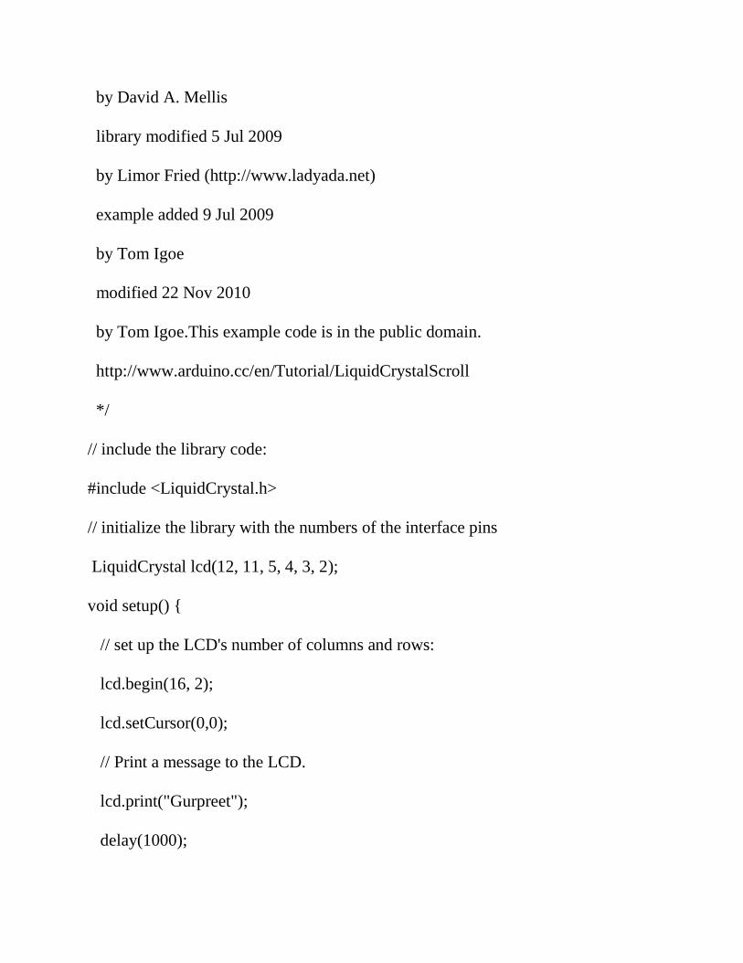
Experiment - LCD Interfacing with Arduino UNO and Scrolling
Names on both Rows
Requirements – LCD, Arduino Board, Breadboard, Jumper Wires, Reistence
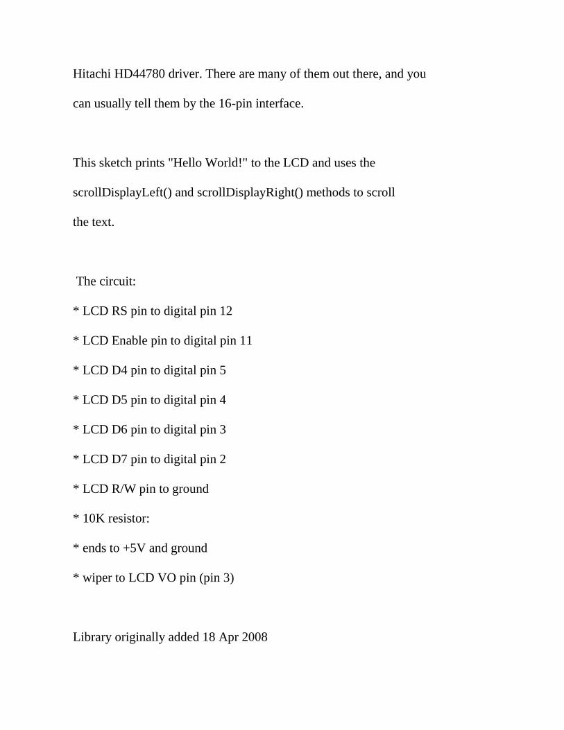
Background – We will use 16X2 graphical LCD display. We will include the
Liquid Crystal Library that works with all LCD displays that are compatible the
Hitachi HD44780 driver.
Fig – 5 LCD Interfacing with Arduino
Code –
/*
LiquidCrystal Library - scrollDisplayLeft() and scrollDisplayRight()
Demonstrates the use a 16x2 LCD display. The LiquidCrystal
library works with all LCD displays that are compatible with the
Hitachi HD44780 driver. There are many of them out there, and you
can usually tell them by the 16-pin interface.
This sketch prints "Hello World!" to the LCD and uses the
scrollDisplayLeft() and scrollDisplayRight() methods to scroll
the text.
The circuit:
* LCD RS pin to digital pin 12
* LCD Enable pin to digital pin 11
* LCD D4 pin to digital pin 5
* LCD D5 pin to digital pin 4
* LCD D6 pin to digital pin 3
* LCD D7 pin to digital pin 2
* LCD R/W pin to ground
* 10K resistor:
* ends to +5V and ground
* wiper to LCD VO pin (pin 3)
Library originally added 18 Apr 2008
by David A. Mellis
library modified 5 Jul 2009
by Limor Fried (http://www.ladyada.net)
example added 9 Jul 2009
by Tom Igoe
modified 22 Nov 2010
by Tom Igoe.This example code is in the public domain.
http://www.arduino.cc/en/Tutorial/LiquidCrystalScroll
*/
// include the library code:
#include <LiquidCrystal.h>
// initialize the library with the numbers of the interface pins
LiquidCrystal lcd(12, 11, 5, 4, 3, 2);
void setup() {
// set up the LCD's number of columns and rows:
lcd.begin(16, 2);
lcd.setCursor(0,0);
// Print a message to the LCD.
lcd.print("Gurpreet");
delay(1000);

lcd.setCursor(0, 1);
// Print a message to the LCD.
lcd.print("singh");
delay(1000);
}
void loop() {
// scroll 29 positions (string length + display length) to the right
// to move it offscreen right:
for (int positionCounter = 0; positionCounter < 8; positionCounter++) {
// scroll one position right:
lcd.scrollDisplayRight();
// wait a bit:
delay(300);
}
// scroll 16 positions (display length + string length) to the left
// to move it back to center:
for (int positionCounter = 7; positionCounter>=0; positionCounter--) {
// scroll one position left:
lcd.scrollDisplayLeft();
// wait a bit:
delay(300); }
//delay at the end of the full loop:
delay(100);
}
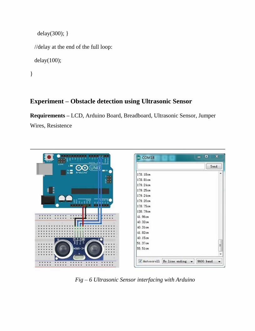
Experiment – Obstacle detection using Ultrasonic Sensor
Requirements – LCD, Arduino Board, Breadboard, Ultrasonic Sensor, Jumper
Wires, Resistence
Fig – 6 Ultrasonic Sensor interfacing with Arduino
Code –
unsigned long echo = 0;
int ultraSoundSignal = 9; // Ultrasound signal pin
unsigned long ultrasoundValue = 0;
void setup()
{
Serial.begin(9600);
pinMode(ultraSoundSignal,OUTPUT);
}
unsigned long ping()
{
pinMode(ultraSoundSignal, OUTPUT); // Switch signalpin to output
digitalWrite(ultraSoundSignal, LOW); // Send low pulse
delayMicroseconds(2); // Wait for 2 microseconds
digitalWrite(ultraSoundSignal, HIGH); // Send high pulse
delayMicroseconds(5); // Wait for 5 microseconds
digitalWrite(ultraSoundSignal, LOW); // Holdoff
pinMode(ultraSoundSignal, INPUT); // Switch signalpin to input
digitalWrite(ultraSoundSignal, HIGH); // Turn on pullup resistor
// please note that pulseIn has a 1sec timeout, which may

// not be desirable. Depending on your sensor specs, you
// can likely bound the time like this -- marcmerlin
// echo = pulseIn(ultraSoundSignal, HIGH, 38000)
echo = pulseIn(ultraSoundSignal, HIGH); //Listen for echo
ultrasoundValue = (echo / 58.138) * .39; //convert to CM then to inches
return ultrasoundValue;
}
void loop()
{
int x = 0;
x = ping();
Serial.println(x);
delay(250); //delay 1/4 seconds
}
Experiment – Using Gyro Sensor and Accelerometer with Arduino
Requirements – LCD, Arduino Board, Breadboard, Gyro Sensor, Accelerometer,
Jumper Wires, Resistence
Code –
#include<Wire.h>
const int MPU_addr=0x68; // I2C address of the MPU-6050
int16_t AcX,AcY,AcZ,Tmp,GyX,GyY,GyZ;
void setup(){
Wire.begin();
Wire.beginTransmission(MPU_addr);
Wire.write(0x6B); // PWR_MGMT_1 register
Wire.write(0); // set to zero (wakes up the MPU-6050)
Wire.endTransmission(true);
Serial.begin(9600);
}
void loop(){
Wire.beginTransmission(MPU_addr);
Wire.write(0x3B); // starting with register 0x3B (ACCEL_XOUT_H)
Wire.endTransmission(false);
Wire.requestFrom(MPU_addr,14,true); // request a total of 14 registers
AcX=Wire.read()<<8|Wire.read(); // 0x3B (ACCEL_XOUT_H) & 0x3C
(ACCEL_XOUT_L)
AcY=Wire.read()<<8|Wire.read(); // 0x3D (ACCEL_YOUT_H) & 0x3E
(ACCEL_YOUT_L)
AcZ=Wire.read()<<8|Wire.read(); // 0x3F (ACCEL_ZOUT_H) & 0x40
(ACCEL_ZOUT_L)
Tmp=Wire.read()<<8|Wire.read(); // 0x41 (TEMP_OUT_H) & 0x42
(TEMP_OUT_L)
GyX=Wire.read()<<8|Wire.read(); // 0x43 (GYRO_XOUT_H) & 0x44
(GYRO_XOUT_L)
GyY=Wire.read()<<8|Wire.read(); // 0x45 (GYRO_YOUT_H) & 0x46
(GYRO_YOUT_L)
GyZ=Wire.read()<<8|Wire.read(); // 0x47 (GYRO_ZOUT_H) & 0x48
(GYRO_ZOUT_L)
Serial.print("AcX = "); Serial.print(AcX);
Serial.print(" | AcY = "); Serial.print(AcY);
Serial.print(" | AcZ = "); Serial.print(AcZ);
Serial.print(" | Tmp = "); Serial.print(Tmp/340.00+36.53); //equation for
temperature in degrees C from datasheet
Serial.print(" | GyX = "); Serial.print(GyX);
Serial.print(" | GyY = "); Serial.print(GyY);
Serial.print(" | GyZ = "); Serial.println(GyZ); delay(333); }
Experiment – To control robocar using Zigbee
Background – In this project we learned to control the robocar through zigbee. To
control the buggy using first we need to interface that zigbee with the pc and
configure the zigbee as in the task we used 2 zigbees one router and the other
coordinator . For configuring the zigbees we require a software named xctu. The
task was to control the buggy with the help of zigbee and the buggy should avoid
the obstacle too for that we inculated the ultrasonic sensor into our buggy.
Code –
// initialize digital pin motor as an output
int LF = 5;
int LB = 6;
int RB = 7;
int RF = 8;
String dir;
// a string to hold incoming data
void setup()
{
Serial.begin(9600);
pinMode(LF, OUTPUT);
pinMode(LB, OUTPUT);
pinMode(RF, OUTPUT);
pinMode(RB, OUTPUT);
}

void loop()
{
dir = Serial.readString();
//if 'W' is received ---> then move forward for 400 milliseconds
if(dir=="W")
{
forward();
delay(400);
stops();
}
//if 'Q' is received ---> then move forward for 1200 milliseconds
else if(dir=="Q")
{
forward();
delay(1200);
stops();
}
//if 'S' is received ---> then move backward for 400 milliseconds
else if(dir=="S")
{

backward();
delay(400);
stops();
}
//if 'D' is received ---> then move right for 210 milliseconds
else if(dir=="D")
{
right();
delay(210);
stops();
}
//if 'A' is received ---> then move left for 210 milliseconds
else if(dir=="A")
{
left();
delay(210);
stops();
}
//if 'X' is received ---> then stops the buggy
else if(dir=="X")
{
stops();
}
//if 'F' is received ---> then move right for 210 milliseconds and 500 milliseconds
else if(dir=="F")
{
right();
delay(210);
forward();
delay(500);
stops();
}
//if 'F' is received ---> then move left for 210 milliseconds and 500 milliseconds
else if(dir=="E")
{
left();
delay(210);
forward();
delay(500);
stops();
}
}
//function for moving forward
void forward()
{
digitalWrite(LF, HIGH);
digitalWrite(LB, LOW);
digitalWrite(RF, HIGH);
digitalWrite(RB, LOW);
}
//function for moving backward
void backward()
{
digitalWrite(LF, LOW);
digitalWrite(LB, HIGH);
digitalWrite(RF, LOW);
digitalWrite(RB, HIGH);
}
//function for turning left
void left()
{
digitalWrite(LF, LOW);
digitalWrite(LB, HIGH);
digitalWrite(RF, HIGH);
digitalWrite(RB, LOW);
}
//function for turning right
void right()
{
digitalWrite(LF, HIGH);