Embed Size (px)
Citation preview
Eclipse BPMN2 Modeler User Guide (Version 1.0.1)
1
INTRODUCTION
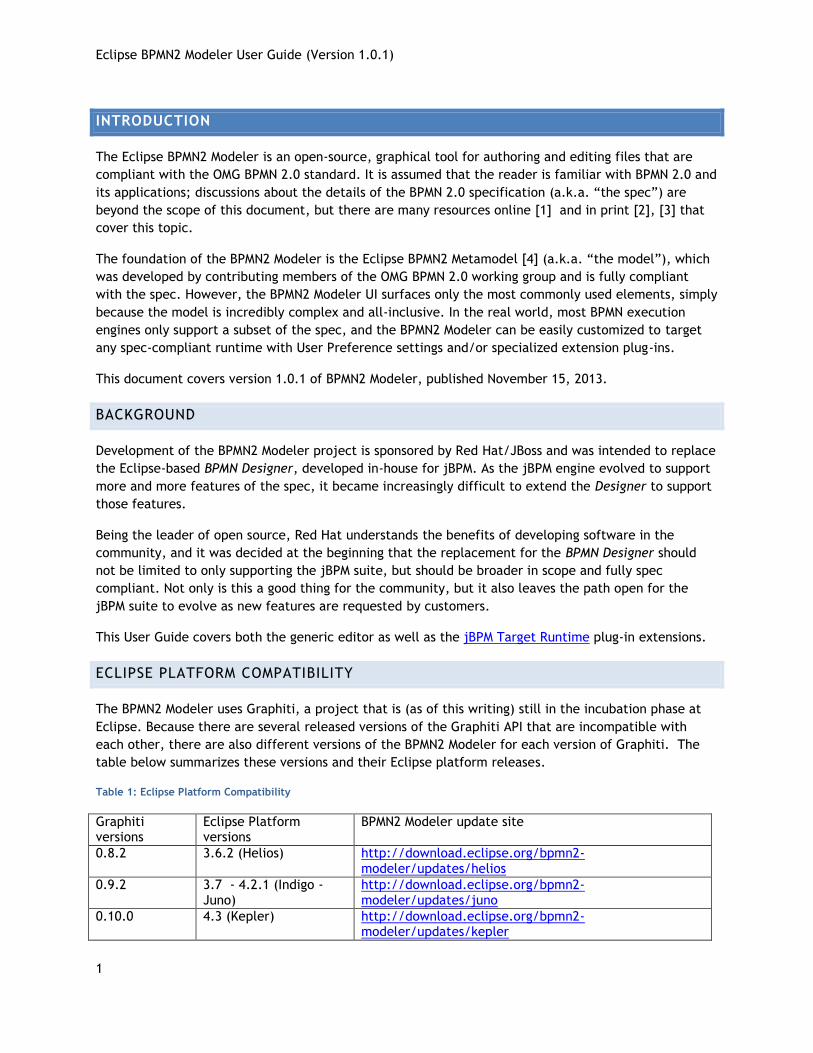
The Eclipse BPMN2 Modeler is an open-source, graphical tool for authoring and editing files that are
compliant with the OMG BPMN 2.0 standard. It is assumed that the reader is familiar with BPMN 2.0 and
its applications; discussions about the details of the BPMN 2.0 specification (a.k.a. “the spec”) are
beyond the scope of this document, but there are many resources online [1] and in print [2], [3] that
cover this topic.
The foundation of the BPMN2 Modeler is the Eclipse BPMN2 Metamodel [4] (a.k.a. “the model”), which
was developed by contributing members of the OMG BPMN 2.0 working group and is fully compliant
with the spec. However, the BPMN2 Modeler UI surfaces only the most commonly used elements, simply
because the model is incredibly complex and all-inclusive. In the real world, most BPMN execution
engines only support a subset of the spec, and the BPMN2 Modeler can be easily customized to target
any spec-compliant runtime with User Preference settings and/or specialized extension plug-ins.
This document covers version 1.0.1 of BPMN2 Modeler, published November 15, 2013.
BACKGROUND
Development of the BPMN2 Modeler project is sponsored by Red Hat/JBoss and was intended to replace
the Eclipse-based BPMN Designer, developed in-house for jBPM. As the jBPM engine evolved to support
more and more features of the spec, it became increasingly difficult to extend the Designer to support
those features.
Being the leader of open source, Red Hat understands the benefits of developing software in the
community, and it was decided at the beginning that the replacement for the BPMN Designer should
not be limited to only supporting the jBPM suite, but should be broader in scope and fully spec
compliant. Not only is this a good thing for the community, but it also leaves the path open for the
jBPM suite to evolve as new features are requested by customers.
This User Guide covers both the generic editor as well as the jBPM Target Runtime plug-in extensions.
ECLIPSE PLATFORM COMPATIBILITY
The BPMN2 Modeler uses Graphiti, a project that is (as of this writing) still in the incubation phase at
Eclipse. Because there are several released versions of the Graphiti API that are incompatible with
each other, there are also different versions of the BPMN2 Modeler for each version of Graphiti. The
table below summarizes these versions and their Eclipse platform releases.
Table 1: Eclipse Platform Compatibility
Graphiti versions
Eclipse Platform versions
BPMN2 Modeler update site
0.8.2 3.6.2 (Helios) http://download.eclipse.org/bpmn2-modeler/updates/helios
0.9.2 3.7 - 4.2.1 (Indigo - Juno)
http://download.eclipse.org/bpmn2-modeler/updates/juno
0.10.0 4.3 (Kepler) http://download.eclipse.org/bpmn2-modeler/updates/kepler
Eclipse BPMN2 Modeler User Guide (Version 1.0.1)
2
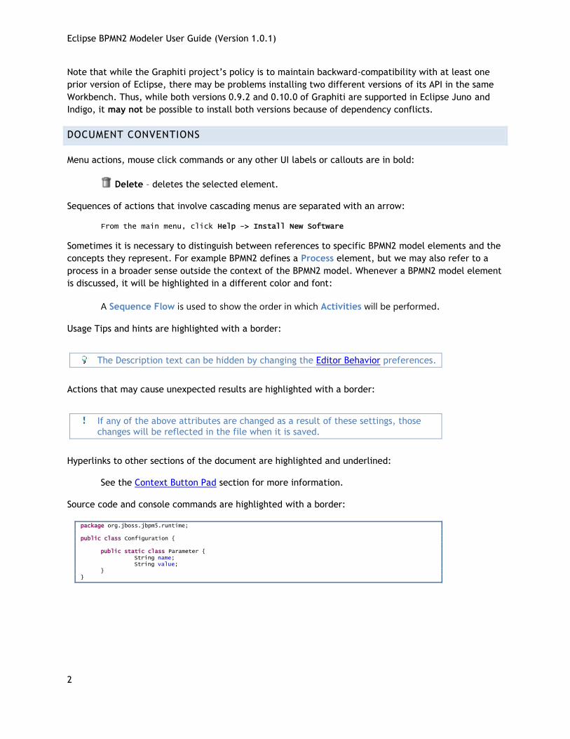
Note that while the Graphiti project’s policy is to maintain backward-compatibility with at least one
prior version of Eclipse, there may be problems installing two different versions of its API in the same
Workbench. Thus, while both versions 0.9.2 and 0.10.0 of Graphiti are supported in Eclipse Juno and
Indigo, it may not be possible to install both versions because of dependency conflicts.
DOCUMENT CONVENTIONS
Menu actions, mouse click commands or any other UI labels or callouts are in bold:
Delete – deletes the selected element.
Sequences of actions that involve cascading menus are separated with an arrow:
From the main menu, click Help -> Install New Software
Sometimes it is necessary to distinguish between references to specific BPMN2 model elements and the
concepts they represent. For example BPMN2 defines a Process element, but we may also refer to a
process in a broader sense outside the context of the BPMN2 model. Whenever a BPMN2 model element
is discussed, it will be highlighted in a different color and font:
A Sequence Flow is used to show the order in which Activities will be performed.
Usage Tips and hints are highlighted with a border:
The Description text can be hidden by changing the Editor Behavior preferences.
Actions that may cause unexpected results are highlighted with a border:
If any of the above attributes are changed as a result of these settings, those changes will be reflected in the file when it is saved.
Hyperlinks to other sections of the document are highlighted and underlined:
See the Context Button Pad section for more information.
Source code and console commands are highlighted with a border:
package org.jboss.jbpm5.runtime; public class Configuration { public static class Parameter { String name; String value; } }
Eclipse BPMN2 Modeler User Guide (Version 1.0.1)
3
INSTALLATION
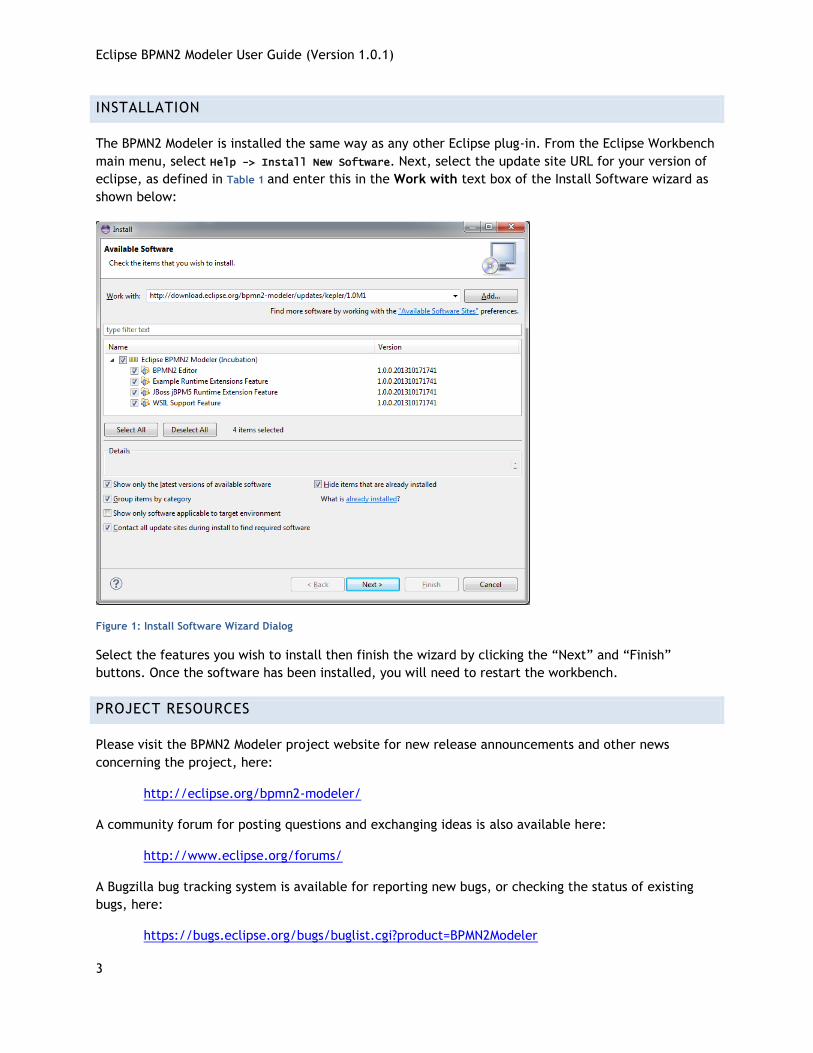
The BPMN2 Modeler is installed the same way as any other Eclipse plug-in. From the Eclipse Workbench
main menu, select Help -> Install New Software. Next, select the update site URL for your version of
eclipse, as defined in Table 1 and enter this in the Work with text box of the Install Software wizard as
shown below:
Figure 1: Install Software Wizard Dialog
Select the features you wish to install then finish the wizard by clicking the “Next” and “Finish”
buttons. Once the software has been installed, you will need to restart the workbench.
PROJECT RESOURCES
Please visit the BPMN2 Modeler project website for new release announcements and other news
concerning the project, here:
http://eclipse.org/bpmn2-modeler/
A community forum for posting questions and exchanging ideas is also available here:
http://www.eclipse.org/forums/
A Bugzilla bug tracking system is available for reporting new bugs, or checking the status of existing
bugs, here:
https://bugs.eclipse.org/bugs/buglist.cgi?product=BPMN2Modeler
Eclipse BPMN2 Modeler User Guide (Version 1.0.1)
4
The source code for the editor as well as several sample extension plug-ins can be found at the Eclipse
Git repository. To clone a local repository, simply use the following Git command:
$ git clone http://git.eclipse.org/gitroot/bpmn2-modeler/org.eclipse.bpmn2-modeler.git
The repository is also mirrored at github.com and can be cloned like this:
$ git clone git://github.com/eclipse/bpmn2-modeler.git
ANATOMY OF THE BPMN2 MODELER
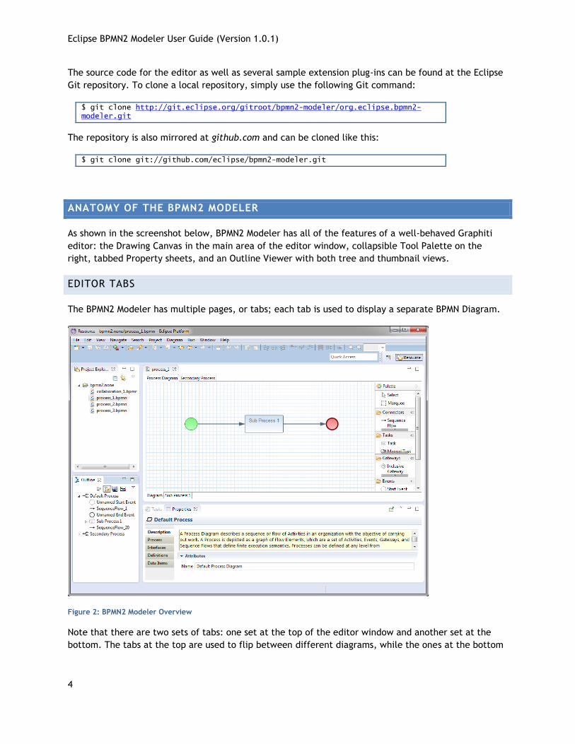
As shown in the screenshot below, BPMN2 Modeler has all of the features of a well-behaved Graphiti
editor: the Drawing Canvas in the main area of the editor window, collapsible Tool Palette on the
right, tabbed Property sheets, and an Outline Viewer with both tree and thumbnail views.
EDITOR TABS
The BPMN2 Modeler has multiple pages, or tabs; each tab is used to display a separate BPMN Diagram.
Figure 2: BPMN2 Modeler Overview
Note that there are two sets of tabs: one set at the top of the editor window and another set at the
bottom. The tabs at the top are used to flip between different diagrams, while the ones at the bottom
Eclipse BPMN2 Modeler User Guide (Version 1.0.1)
5
are the contents of collapsed Sub-Processes contained within the same diagram. Procedures for
managing diagram and Sub-Process tabs will be discussed in a later section.
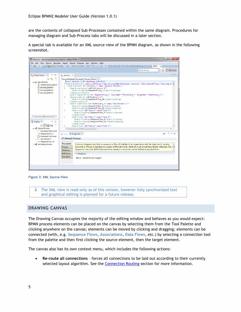
A special tab is available for an XML source view of the BPMN diagram, as shown in the following
screenshot.
Figure 3: XML Source View
The XML view is read-only as of this version, however fully synchronized text and graphical editing is planned for a future release.
DRAWING CANVAS
The Drawing Canvas occupies the majority of the editing window and behaves as you would expect:
BPMN process elements can be placed on the canvas by selecting them from the Tool Palette and
clicking anywhere on the canvas; elements can be moved by clicking and dragging; elements can be
connected (with, e.g. Sequence Flows, Associations, Data Flows, etc.) by selecting a connection tool
from the palette and then first clicking the source element, then the target element.
The canvas also has its own context menu, which includes the following actions:
Re-route all connections – forces all connections to be laid out according to their currently
selected layout algorithm. See the Connection Routing section for more information.
Eclipse BPMN2 Modeler User Guide (Version 1.0.1)
6
Validate – checks the file for missing/incorrectly configured elements and reports these in the
Problems view. Problems are also highlighted on the canvas with a warning ( ) or error ( )
decorator on the problem element.
Show/hide Source View – is used to show or hide the XML source tab.
Delete Diagram – deletes the currently active diagram tab.
Export Diagram – is used to save a snapshot image of the entire diagram, in various selectable
image formats and sizes. See the Export Diagram Dialog section.
TOOL PALETTE
The Tool Palette is, by default, located along the right edge of the Drawing Canvas. It consists of
several “tool drawers” which contain the “tools” that are dragged onto the Drawing Canvas to create
BPMN2 elements.
OUTLINE VIEW
The Outline View is separate from the editor and is intended to show a hierarchical, tree oriented view
of the file. This view is synchronized with the Drawing Canvas; when an element is selected on the
canvas, it is highlighted in the Outline View. Conversely when an item in the Outline is selected, it is
also highlighted on the Drawing Canvas.
PROPERTY VIEW
The Property View is used to edit the attributes of the currently selected element. This view is also
synchronized with the Outline View such that when a tree element is selected in the Outline, its
attributes are displayed in the Property View.
MENU & TOOLBAR
Diagram Main Menu Action – This Main Menu bar item allows you to create a new Process, Choreography
or Collaboration diagram. The new diagram will be initially empty and appear as a new tab at the top
of the editor window. See the section on BPMN 2.0 Diagram Types for more information.
Undo/Redo – These Toolbar actions undo or redo the last editing operation performed. If the
operation changed some attribute of an element (for example, its name) the undo/redo affects only
that attribute.
Zoom – This Toolbar action are used to magnify or reduce the diagram.
Alignment Tools – These Toolbar actions are used to align multiple shapes with
each other either horizontally, vertically, or normalize their widths or heights.
Hide Context Buttons – This Toolbar action disables the Context Button Pad. When the mouse is
hovered over an element, an irregularly shaped “pad” pops up and surrounds the element. This pad
contains a number of editing buttons which affect the element. The Hide Context Buttons Toolbar
toggle button disables the display of this Button Pad. See the Context Button Pad section for more
information.
Eclipse BPMN2 Modeler User Guide (Version 1.0.1)
7
NEW BPMN2 FILE WIZARDS
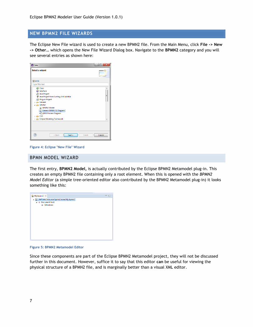
The Eclipse New File wizard is used to create a new BPMN2 file. From the Main Menu, click File -> New
-> Other… which opens the New File Wizard Dialog box. Navigate to the BPMN2 category and you will
see several entries as shown here:
Figure 4: Eclipse "New File" Wizard
BPMN MODEL WIZARD
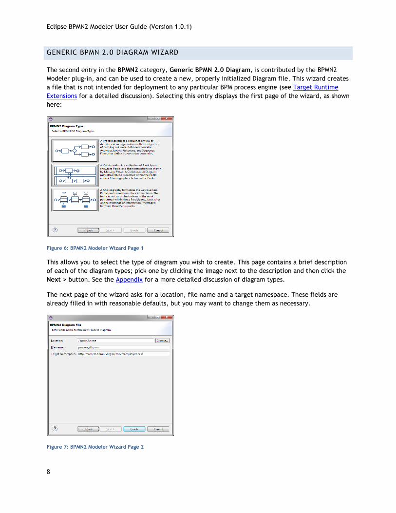
The first entry, BPMN2 Model, is actually contributed by the Eclipse BPMN2 Metamodel plug-in. This
creates an empty BPMN2 file containing only a root element. When this is opened with the BPMN2
Model Editor (a simple tree-oriented editor also contributed by the BPMN2 Metamodel plug-in) it looks
something like this:
Figure 5: BPMN2 Metamodel Editor
Since these components are part of the Eclipse BPMN2 Metamodel project, they will not be discussed
further in this document. However, suffice it to say that this editor can be useful for viewing the
physical structure of a BPMN2 file, and is marginally better than a visual XML editor.
Eclipse BPMN2 Modeler User Guide (Version 1.0.1)
8
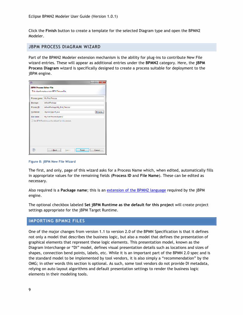
GENERIC BPMN 2.0 DIAGRAM WIZARD
The second entry in the BPMN2 category, Generic BPMN 2.0 Diagram, is contributed by the BPMN2
Modeler plug-in, and can be used to create a new, properly initialized Diagram file. This wizard creates
a file that is not intended for deployment to any particular BPM process engine (see Target Runtime
Extensions for a detailed discussion). Selecting this entry displays the first page of the wizard, as shown
here:
Figure 6: BPMN2 Modeler Wizard Page 1
This allows you to select the type of diagram you wish to create. This page contains a brief description
of each of the diagram types; pick one by clicking the image next to the description and then click the
Next > button. See the Appendix for a more detailed discussion of diagram types.
The next page of the wizard asks for a location, file name and a target namespace. These fields are
already filled in with reasonable defaults, but you may want to change them as necessary.
Figure 7: BPMN2 Modeler Wizard Page 2
Eclipse BPMN2 Modeler User Guide (Version 1.0.1)
9
Click the Finish button to create a template for the selected Diagram type and open the BPMN2
Modeler.
JBPM PROCESS DIAGRAM WIZARD
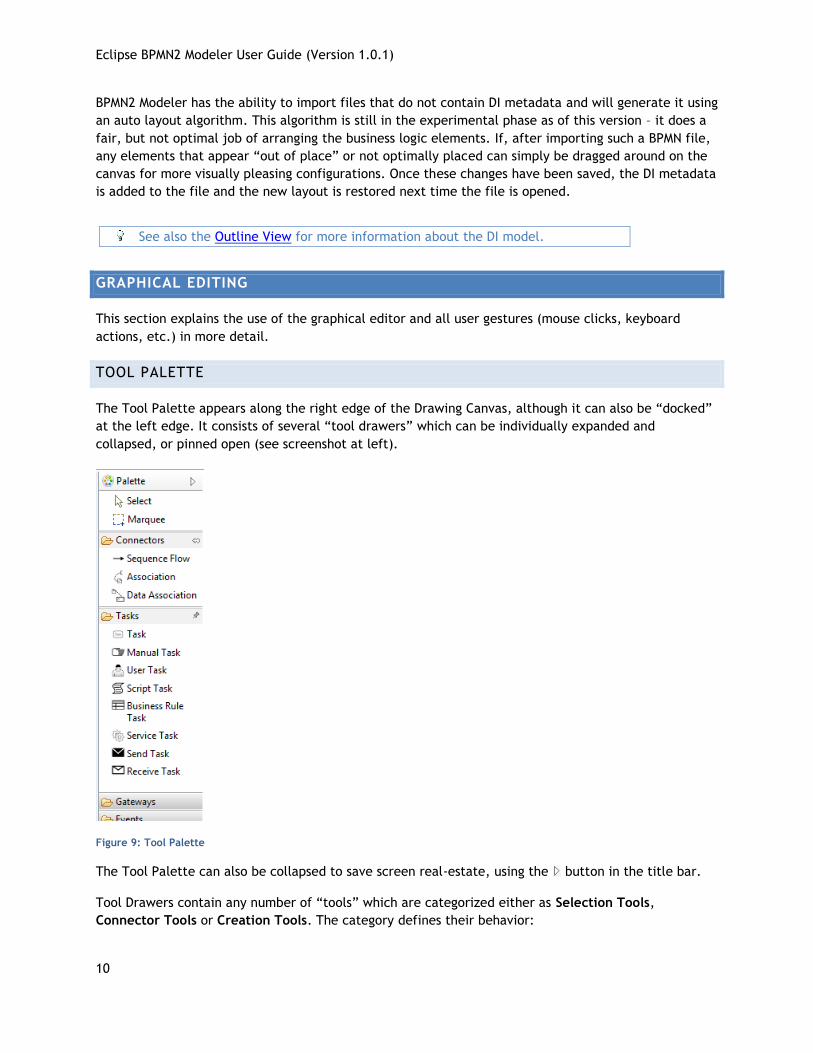
Part of the BPMN2 Modeler extension mechanism is the ability for plug-ins to contribute New File
wizard entries. These will appear as additional entries under the BPMN2 category. Here, the jBPM
Process Diagram wizard is specifically designed to create a process suitable for deployment to the
jBPM engine.
Figure 8: jBPM New File Wizard
The first, and only, page of this wizard asks for a Process Name which, when edited, automatically fills
in appropriate values for the remaining fields (Process ID and File Name). These can be edited as
necessary.
Also required is a Package name; this is an extension of the BPMN2 language required by the jBPM
engine.
The optional checkbox labeled Set jBPM Runtime as the default for this project will create project
settings appropriate for the jBPM Target Runtime.
IMPORTING BPMN2 FILES
One of the major changes from version 1.1 to version 2.0 of the BPMN Specification is that it defines
not only a model that describes the business logic, but also a model that defines the presentation of
graphical elements that represent these logic elements. This presentation model, known as the
Diagram Interchange or “DI” model, defines visual presentation details such as locations and sizes of
shapes, connection bend points, labels, etc. While it is an important part of the BPMN 2.0 spec and is
the standard model to be implemented by tool vendors, it is also simply a “recommendation” by the
OMG; in other words this section is optional. As such, some tool vendors do not provide DI metadata,
relying on auto layout algorithms and default presentation settings to render the business logic
elements in their modeling tools.
Eclipse BPMN2 Modeler User Guide (Version 1.0.1)
10
BPMN2 Modeler has the ability to import files that do not contain DI metadata and will generate it using
an auto layout algorithm. This algorithm is still in the experimental phase as of this version – it does a
fair, but not optimal job of arranging the business logic elements. If, after importing such a BPMN file,
any elements that appear “out of place” or not optimally placed can simply be dragged around on the
canvas for more visually pleasing configurations. Once these changes have been saved, the DI metadata
is added to the file and the new layout is restored next time the file is opened.
See also the Outline View for more information about the DI model.
GRAPHICAL EDITING
This section explains the use of the graphical editor and all user gestures (mouse clicks, keyboard
actions, etc.) in more detail.
TOOL PALETTE
The Tool Palette appears along the right edge of the Drawing Canvas, although it can also be “docked”
at the left edge. It consists of several “tool drawers” which can be individually expanded and
collapsed, or pinned open (see screenshot at left).
Figure 9: Tool Palette
The Tool Palette can also be collapsed to save screen real-estate, using the button in the title bar.
Tool Drawers contain any number of “tools” which are categorized either as Selection Tools,
Connector Tools or Creation Tools. The category defines their behavior:
Eclipse BPMN2 Modeler User Guide (Version 1.0.1)
11
Selection Tools remain active as long as they are enabled. The Select tool allows you to select
individual elements on the Drawing Canvas by clicking the primary (left) mouse button; holding either
the Control or Shift key allows you to select additional elements. The Marquee tool is used to select
multiple elements by dragging a rectangular selection box around the elements. Additional elements
can be selected by switching back to the Select tool.
Connector Tools also remain active as long as they are enabled. To create a connection between two
elements, click the first element (the “source” of the connection) and then the second (the “target”).
Creation Tools are “single shot”, that is they are only active for a single mouse click action. Once the
element has been created on the Drawing Canvas, the Select tool becomes active again.
Pressing the ESC key while a tool is active cancels its action, and re-activates the Select tool.
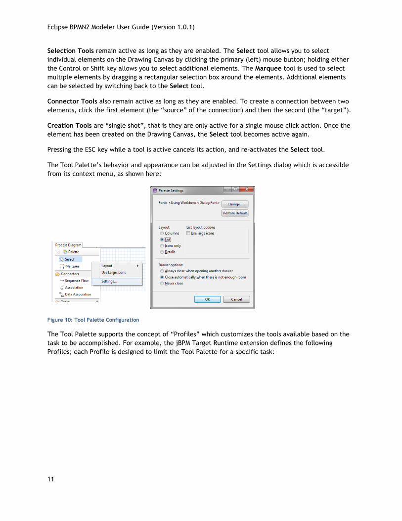
The Tool Palette’s behavior and appearance can be adjusted in the Settings dialog which is accessible
from its context menu, as shown here:
Figure 10: Tool Palette Configuration
The Tool Palette supports the concept of “Profiles” which customizes the tools available based on the
task to be accomplished. For example, the jBPM Target Runtime extension defines the following
Profiles; each Profile is designed to limit the Tool Palette for a specific task:
Eclipse BPMN2 Modeler User Guide (Version 1.0.1)
12
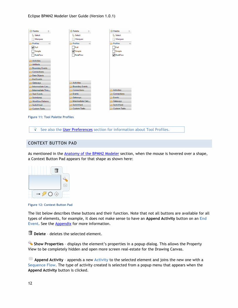
Figure 11: Tool Palette Profiles
See also the User Preferences section for information about Tool Profiles.
CONTEXT BUTTON PAD
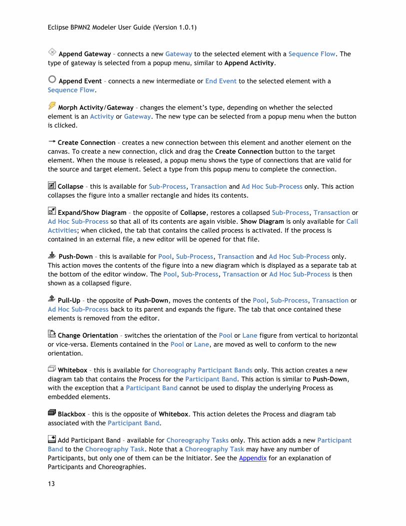
As mentioned in the Anatomy of the BPMN2 Modeler section, when the mouse is hovered over a shape,
a Context Button Pad appears for that shape as shown here:
Figure 12: Context Button Pad
The list below describes these buttons and their function. Note that not all buttons are available for all
types of elements, for example, it does not make sense to have an Append Activity button on an End
Event. See the Appendix for more information.
Delete – deletes the selected element.
Show Properties – displays the element’s properties in a popup dialog. This allows the Property
View to be completely hidden and open more screen real-estate for the Drawing Canvas.
Append Activity – appends a new Activity to the selected element and joins the new one with a
Sequence Flow. The type of activity created is selected from a popup menu that appears when the
Append Activity button is clicked.
Eclipse BPMN2 Modeler User Guide (Version 1.0.1)
13
Append Gateway – connects a new Gateway to the selected element with a Sequence Flow. The
type of gateway is selected from a popup menu, similar to Append Activity.
Append Event – connects a new intermediate or End Event to the selected element with a
Sequence Flow.
Morph Activity/Gateway – changes the element’s type, depending on whether the selected
element is an Activity or Gateway. The new type can be selected from a popup menu when the button
is clicked.
Create Connection – creates a new connection between this element and another element on the
canvas. To create a new connection, click and drag the Create Connection button to the target
element. When the mouse is released, a popup menu shows the type of connections that are valid for
the source and target element. Select a type from this popup menu to complete the connection.
Collapse – this is available for Sub-Process, Transaction and Ad Hoc Sub-Process only. This action
collapses the figure into a smaller rectangle and hides its contents.
Expand/Show Diagram – the opposite of Collapse, restores a collapsed Sub-Process, Transaction or
Ad Hoc Sub-Process so that all of its contents are again visible. Show Diagram is only available for Call
Activities; when clicked, the tab that contains the called process is activated. If the process is
contained in an external file, a new editor will be opened for that file.
Push-Down – this is available for Pool, Sub-Process, Transaction and Ad Hoc Sub-Process only.
This action moves the contents of the figure into a new diagram which is displayed as a separate tab at
the bottom of the editor window. The Pool, Sub-Process, Transaction or Ad Hoc Sub-Process is then
shown as a collapsed figure.
Pull-Up – the opposite of Push-Down, moves the contents of the Pool, Sub-Process, Transaction or
Ad Hoc Sub-Process back to its parent and expands the figure. The tab that once contained these
elements is removed from the editor.
Change Orientation – switches the orientation of the Pool or Lane figure from vertical to horizontal
or vice-versa. Elements contained in the Pool or Lane, are moved as well to conform to the new
orientation.
Whitebox – this is available for Choreography Participant Bands only. This action creates a new
diagram tab that contains the Process for the Participant Band. This action is similar to Push-Down,
with the exception that a Participant Band cannot be used to display the underlying Process as
embedded elements.
Blackbox – this is the opposite of Whitebox. This action deletes the Process and diagram tab
associated with the Participant Band.
Add Participant Band – available for Choreography Tasks only. This action adds a new Participant
Band to the Choreography Task. Note that a Choreography Task may have any number of
Participants, but only one of them can be the Initiator. See the Appendix for an explanation of
Participants and Choreographies.
Eclipse BPMN2 Modeler User Guide (Version 1.0.1)
14
Remove Participant Band – available for Choreography Participant Bands only. This action
removes a Participant Band from its Choreography Task.
Add Message – available for Choreography Participant Bands only. This action adds a Message to
the Participant Band.
Remove Message – available for Choreography Participant Bands only. This action removes the
Message attached to the Participant Band. This has the same effect as selecting the attached Message
and deleting it.
CONNECTIONS
Connections between shapes can be created in one of three ways: using the Connector tools from the
Tool Palette, using the Create Connection Context Button and implicitly using the Append Context
buttons.
When a Connection is selected, one or more “handles” will appear on the connection line. The
connection’s path can be altered by dragging one of these handles. Note that new handles will appear
as a handle is dragged to create new line segments. The locations of these handles are known as
“bendpoints” to the graphical editor, but are stored as Waypoint elements in the BPMN file.
BPMN2 Modeler allows you to specify different layout styles (“Routings”) for connections. Routing
styles are applied by connection type, so for example, all Sequence Flows can be laid out using
Manhattan routing, all Associations can use Manual Bendpoint routing, and so on. The Editor
Appearance Preferences section explains how to configure connection routing styles.
Connections may also have labels, which are edited using the Property View. The labels are situated
about the center of the connection, but may be dragged to a different location with the mouse.
PROPERTY VIEW
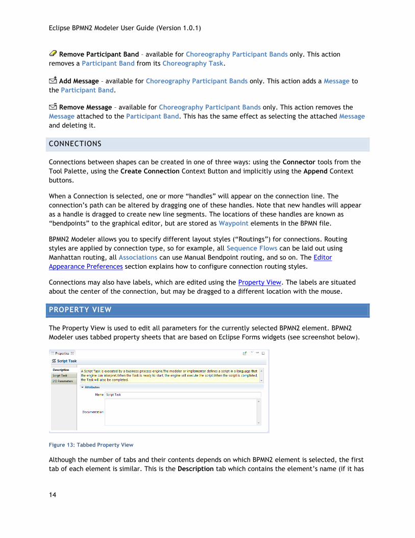
The Property View is used to edit all parameters for the currently selected BPMN2 element. BPMN2
Modeler uses tabbed property sheets that are based on Eclipse Forms widgets (see screenshot below).
Figure 13: Tabbed Property View
Although the number of tabs and their contents depends on which BPMN2 element is selected, the first
tab of each element is similar. This is the Description tab which contains the element’s name (if it has
Eclipse BPMN2 Modeler User Guide (Version 1.0.1)
15
one), a brief description of the element type, and a Documentation edit box which can be used to
document the element.
The Description text can be hidden by changing the Editor Behavior preferences.
The element’s ID attribute will also be displayed on this tab, if its visibility is enabled (see Editor
Behavior preferences.)
EDITING WIDGETS
If you are familiar with Eclipse Forms, most of the Property View editing widgets should be familiar
(e.g. Text Editing fields, Check Boxes, Combo Boxes, etc.) The Eclipse Plug-in Manifest editor is an
example of how these Form widgets look and behave.
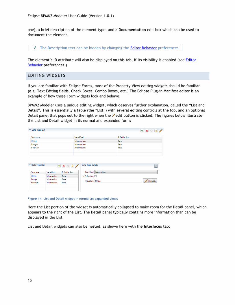
BPMN2 Modeler uses a unique editing widget, which deserves further explanation, called the “List and
Detail”. This is essentially a table (the “List”) with several editing controls at the top, and an optional
Detail panel that pops out to the right when the edit button is clicked. The figures below illustrate
the List and Detail widget in its normal and expanded form:
Figure 14: List and Detail widget in normal an expanded views
Here the List portion of the widget is automatically collapsed to make room for the Detail panel, which
appears to the right of the List. The Detail panel typically contains more information than can be
displayed in the List.
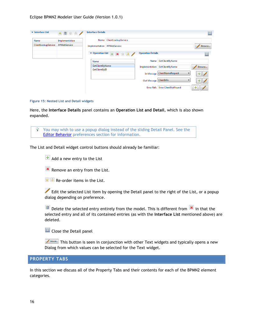
List and Detail widgets can also be nested, as shown here with the Interfaces tab:
Eclipse BPMN2 Modeler User Guide (Version 1.0.1)
16
Figure 15: Nested List and Detail widgets
Here, the Interface Details panel contains an Operation List and Detail, which is also shown
expanded.
You may wish to use a popup dialog instead of the sliding Detail Panel. See the
Editor Behavior preferences section for information.
The List and Detail widget control buttons should already be familiar:
Add a new entry to the List
Remove an entry from the List.
Re-order items in the List.
Edit the selected List item by opening the Detail panel to the right of the List, or a popup
dialog depending on preference.
Delete the selected entry entirely from the model. This is different from in that the
selected entry and all of its contained entries (as with the Interface List mentioned above) are
deleted.
Close the Detail panel
This button is seen in conjunction with other Text widgets and typically opens a new
Dialog from which values can be selected for the Text widget.
PROPERTY TABS
In this section we discuss all of the Property Tabs and their contents for each of the BPMN2 element
categories.
Eclipse BPMN2 Modeler User Guide (Version 1.0.1)
17
PROCESS DIAGRAM
This Property Tab is displayed when the Drawing Canvas is clicked, or if a Process element is selected
from the Outline View.
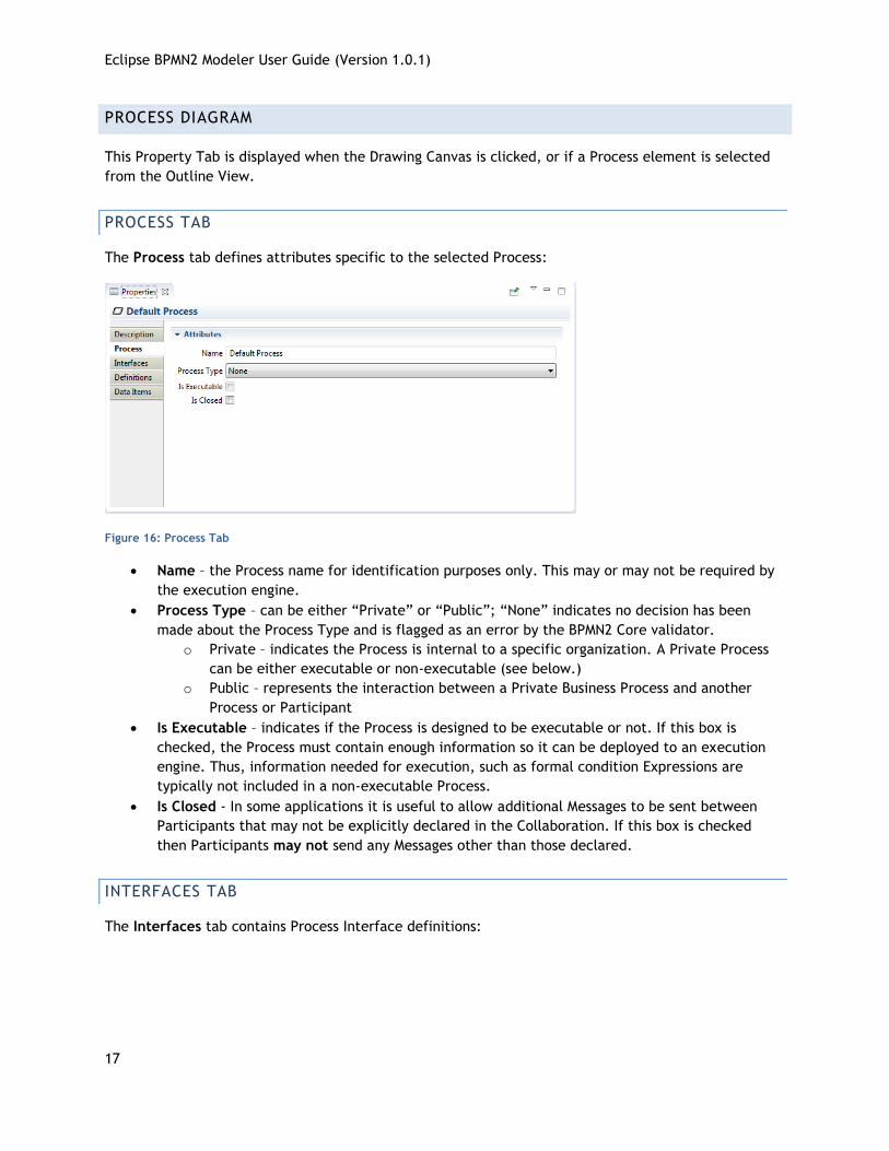
PROCESS TAB
The Process tab defines attributes specific to the selected Process:
Figure 16: Process Tab
Name – the Process name for identification purposes only. This may or may not be required by
the execution engine.
Process Type – can be either “Private” or “Public”; “None” indicates no decision has been
made about the Process Type and is flagged as an error by the BPMN2 Core validator.
o Private – indicates the Process is internal to a specific organization. A Private Process
can be either executable or non-executable (see below.)
o Public – represents the interaction between a Private Business Process and another
Process or Participant
Is Executable – indicates if the Process is designed to be executable or not. If this box is
checked, the Process must contain enough information so it can be deployed to an execution
engine. Thus, information needed for execution, such as formal condition Expressions are
typically not included in a non-executable Process.
Is Closed - In some applications it is useful to allow additional Messages to be sent between
Participants that may not be explicitly declared in the Collaboration. If this box is checked
then Participants may not send any Messages other than those declared.
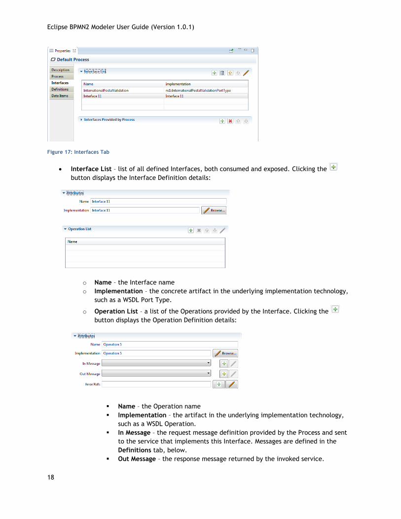
INTERFACES TAB
The Interfaces tab contains Process Interface definitions:
Eclipse BPMN2 Modeler User Guide (Version 1.0.1)
18
Figure 17: Interfaces Tab
Interface List – list of all defined Interfaces, both consumed and exposed. Clicking the
button displays the Interface Definition details:
o Name – the Interface name
o Implementation – the concrete artifact in the underlying implementation technology,
such as a WSDL Port Type.
o Operation List – a list of the Operations provided by the Interface. Clicking the
button displays the Operation Definition details:
Name – the Operation name
Implementation – the artifact in the underlying implementation technology,
such as a WSDL Operation.
In Message – the request message definition provided by the Process and sent
to the service that implements this Interface. Messages are defined in the
Definitions tab, below.
Out Message – the response message returned by the invoked service.
Eclipse BPMN2 Modeler User Guide (Version 1.0.1)
19
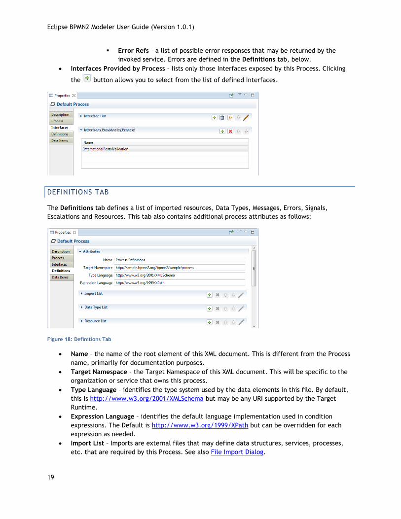
Error Refs – a list of possible error responses that may be returned by the
invoked service. Errors are defined in the Definitions tab, below.
Interfaces Provided by Process – lists only those Interfaces exposed by this Process. Clicking
the button allows you to select from the list of defined Interfaces.
DEFINITIONS TAB
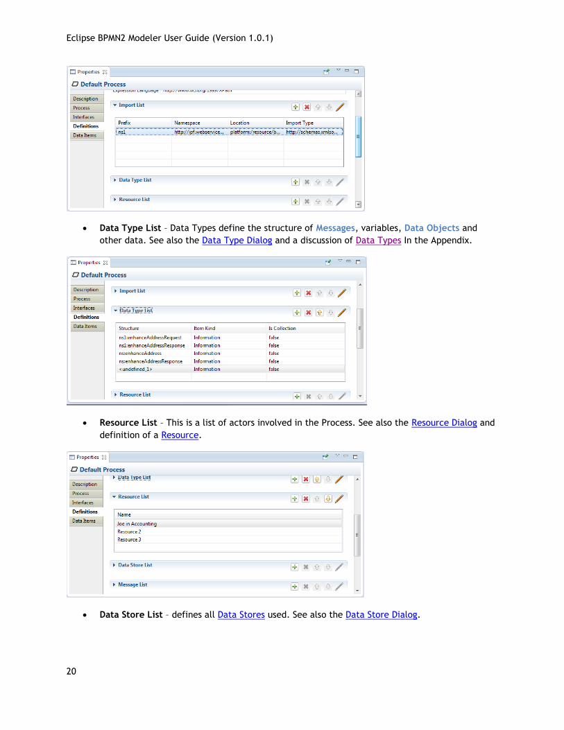
The Definitions tab defines a list of imported resources, Data Types, Messages, Errors, Signals,
Escalations and Resources. This tab also contains additional process attributes as follows:
Figure 18: Definitions Tab
Name – the name of the root element of this XML document. This is different from the Process
name, primarily for documentation purposes.
Target Namespace – the Target Namespace of this XML document. This will be specific to the
organization or service that owns this process.
Type Language – identifies the type system used by the data elements in this file. By default,
this is http://www.w3.org/2001/XMLSchema but may be any URI supported by the Target
Runtime.
Expression Language – identifies the default language implementation used in condition
expressions. The Default is http://www.w3.org/1999/XPath but can be overridden for each
expression as needed.
Import List – Imports are external files that may define data structures, services, processes,
etc. that are required by this Process. See also File Import Dialog.
Eclipse BPMN2 Modeler User Guide (Version 1.0.1)
20
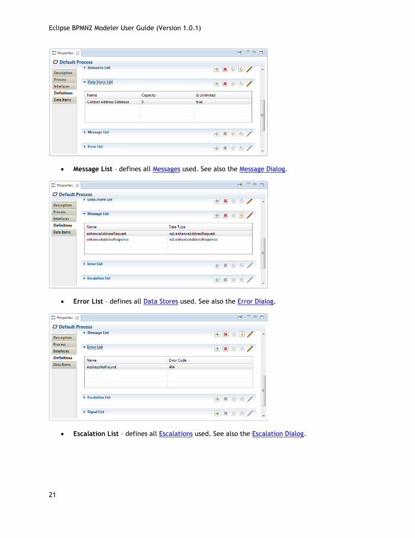
Data Type List – Data Types define the structure of Messages, variables, Data Objects and
other data. See also the Data Type Dialog and a discussion of Data Types In the Appendix.
Resource List – This is a list of actors involved in the Process. See also the Resource Dialog and
definition of a Resource.
Data Store List – defines all Data Stores used. See also the Data Store Dialog.
Eclipse BPMN2 Modeler User Guide (Version 1.0.1)
21
Message List – defines all Messages used. See also the Message Dialog.
Error List – defines all Data Stores used. See also the Error Dialog.
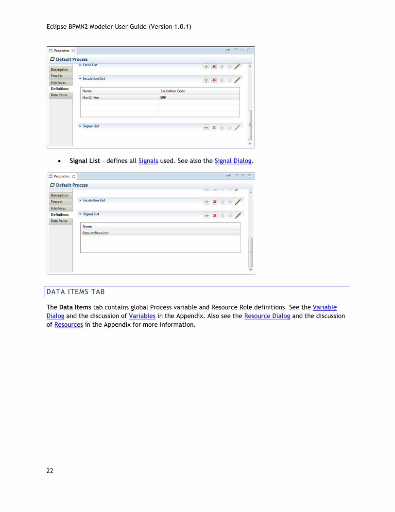
Escalation List – defines all Escalations used. See also the Escalation Dialog.
Eclipse BPMN2 Modeler User Guide (Version 1.0.1)
22
Signal List – defines all Signals used. See also the Signal Dialog.
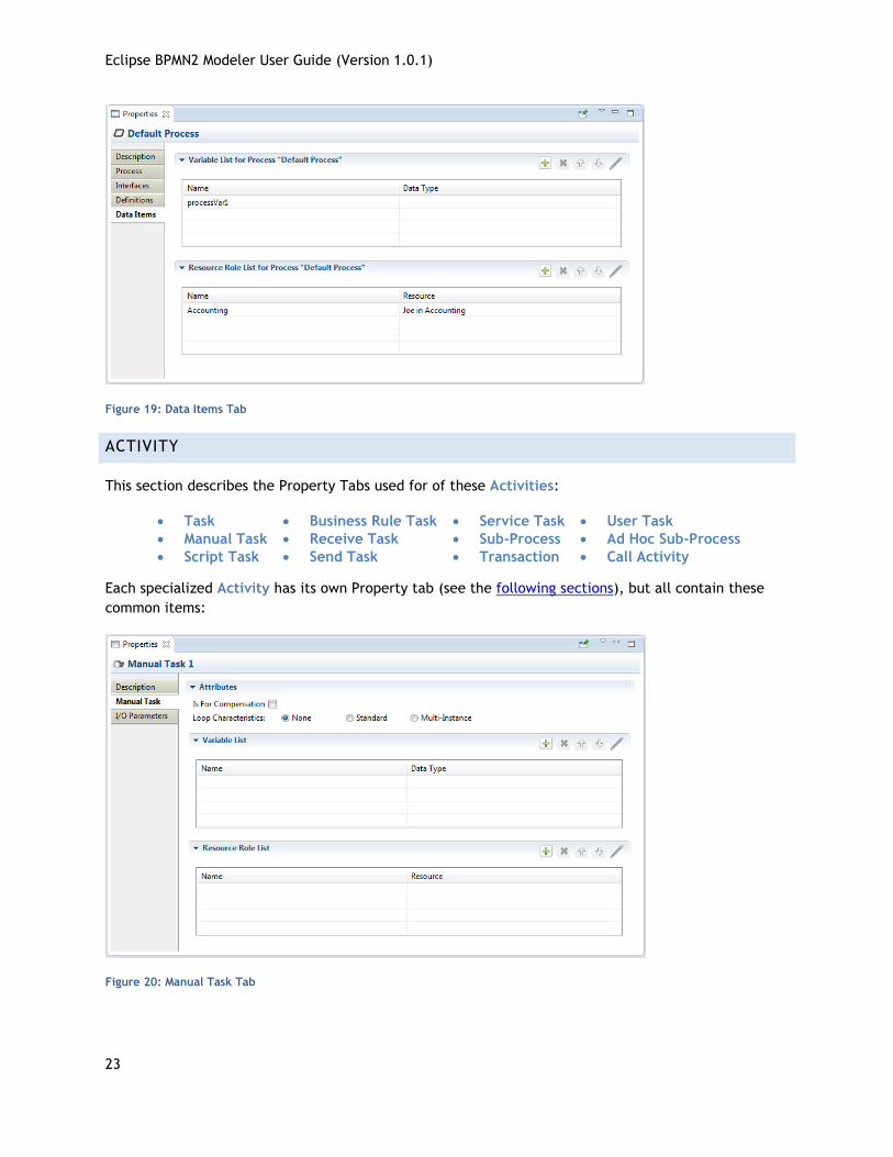
DATA ITEMS TAB
The Data Items tab contains global Process variable and Resource Role definitions. See the Variable
Dialog and the discussion of Variables in the Appendix. Also see the Resource Dialog and the discussion
of Resources in the Appendix for more information.
Eclipse BPMN2 Modeler User Guide (Version 1.0.1)
23
Figure 19: Data Items Tab
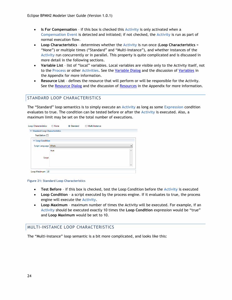
ACTIVITY
This section describes the Property Tabs used for of these Activities:
Task Business Rule Task Service Task User Task
Manual Task Receive Task Sub-Process Ad Hoc Sub-Process
Script Task Send Task Transaction Call Activity
Each specialized Activity has its own Property tab (see the following sections), but all contain these
common items:
Figure 20: Manual Task Tab
Eclipse BPMN2 Modeler User Guide (Version 1.0.1)
24
Is For Compensation – if this box is checked this Activity is only activated when a
Compensation Event is detected and initiated; if not checked, the Activity is run as part of
normal execution flow.
Loop Characteristics – determines whether the Activity is run once (Loop Characteristics =
“None”) or multiple times (“Standard” and “Multi-Instance”), and whether instances of the
Activity run concurrently or in parallel. This property is quite complicated and is discussed in
more detail in the following sections.
Variable List – list of “local” variables. Local variables are visible only to the Activity itself, not
to the Process or other Activities. See the Variable Dialog and the discussion of Variables in
the Appendix for more information.
Resource List – defines the resource that will perform or will be responsible for the Activity.
See the Resource Dialog and the discussion of Resources in the Appendix for more information.
STANDARD LOOP CHARACTERISTICS
The “Standard” loop semantics is to simply execute an Activity as long as some Expression condition
evaluates to true. The condition can be tested before or after the Activity is executed. Also, a
maximum limit may be set on the total number of executions.
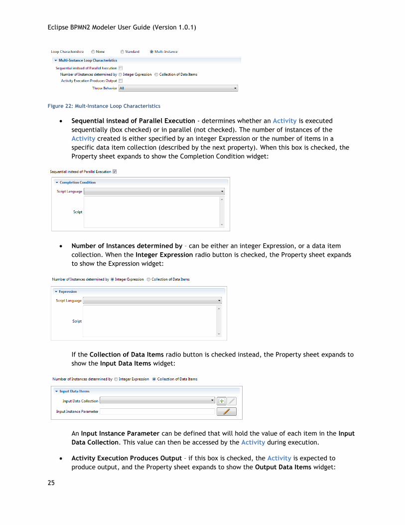
Figure 21: Standard Loop Characteristics
Test Before – if this box is checked, test the Loop Condition before the Activity is executed
Loop Condition – a script executed by the process engine. If it evaluates to true, the process
engine will execute the Activity.
Loop Maximum – maximum number of times the Activity will be executed. For example, if an
Activity should be executed exactly 10 times the Loop Condition expression would be “true”
and Loop Maximum would be set to 10.
MULTI-INSTANCE LOOP CHARACTERISTICS
The “Multi-Instance” loop semantic is a bit more complicated, and looks like this:
Eclipse BPMN2 Modeler User Guide (Version 1.0.1)
25
Figure 22: Mult-Instance Loop Characteristics
Sequential instead of Parallel Execution - determines whether an Activity is executed
sequentially (box checked) or in parallel (not checked). The number of instances of the
Activity created is either specified by an integer Expression or the number of items in a
specific data item collection (described by the next property). When this box is checked, the
Property sheet expands to show the Completion Condition widget:
Number of Instances determined by – can be either an integer Expression, or a data item
collection. When the Integer Expression radio button is checked, the Property sheet expands
to show the Expression widget:
If the Collection of Data Items radio button is checked instead, the Property sheet expands to
show the Input Data Items widget:
An Input Instance Parameter can be defined that will hold the value of each item in the Input
Data Collection. This value can then be accessed by the Activity during execution.
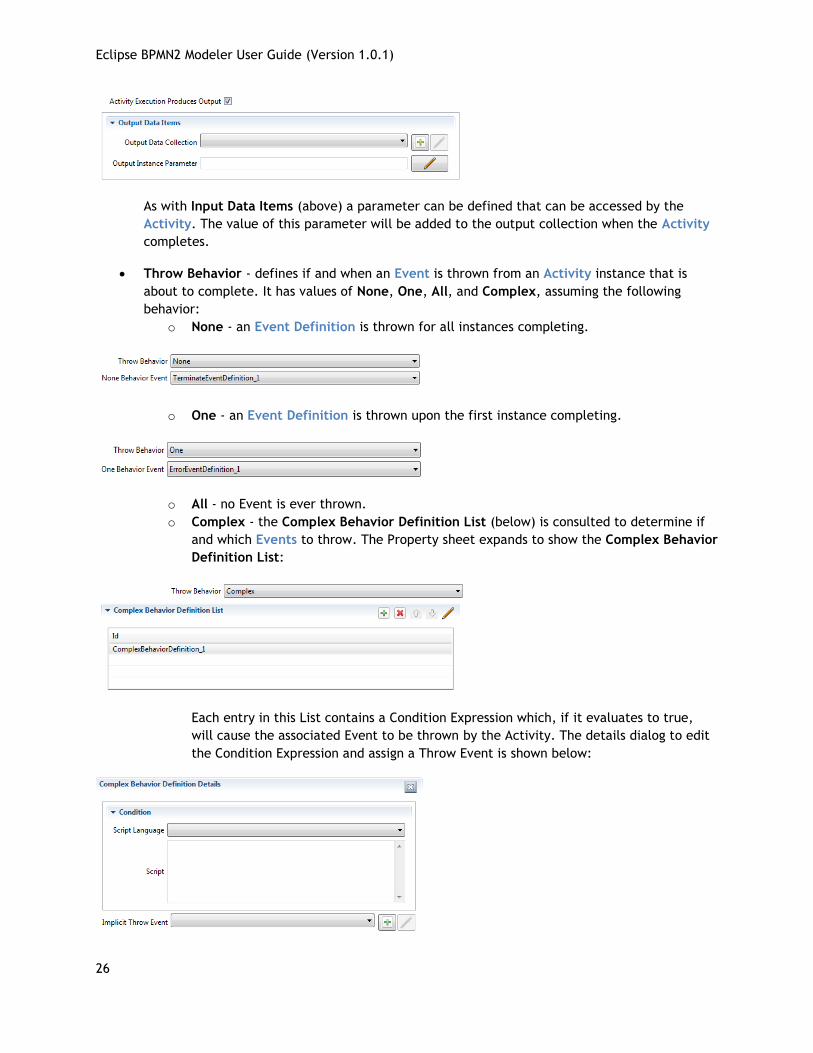
Activity Execution Produces Output – if this box is checked, the Activity is expected to
produce output, and the Property sheet expands to show the Output Data Items widget:
Eclipse BPMN2 Modeler User Guide (Version 1.0.1)
26
As with Input Data Items (above) a parameter can be defined that can be accessed by the
Activity. The value of this parameter will be added to the output collection when the Activity
completes.
Throw Behavior - defines if and when an Event is thrown from an Activity instance that is
about to complete. It has values of None, One, All, and Complex, assuming the following
behavior:
o None - an Event Definition is thrown for all instances completing.
o One - an Event Definition is thrown upon the first instance completing.
o All - no Event is ever thrown.
o Complex - the Complex Behavior Definition List (below) is consulted to determine if
and which Events to throw. The Property sheet expands to show the Complex Behavior
Definition List:
Each entry in this List contains a Condition Expression which, if it evaluates to true,
will cause the associated Event to be thrown by the Activity. The details dialog to edit
the Condition Expression and assign a Throw Event is shown below:
Eclipse BPMN2 Modeler User Guide (Version 1.0.1)
27
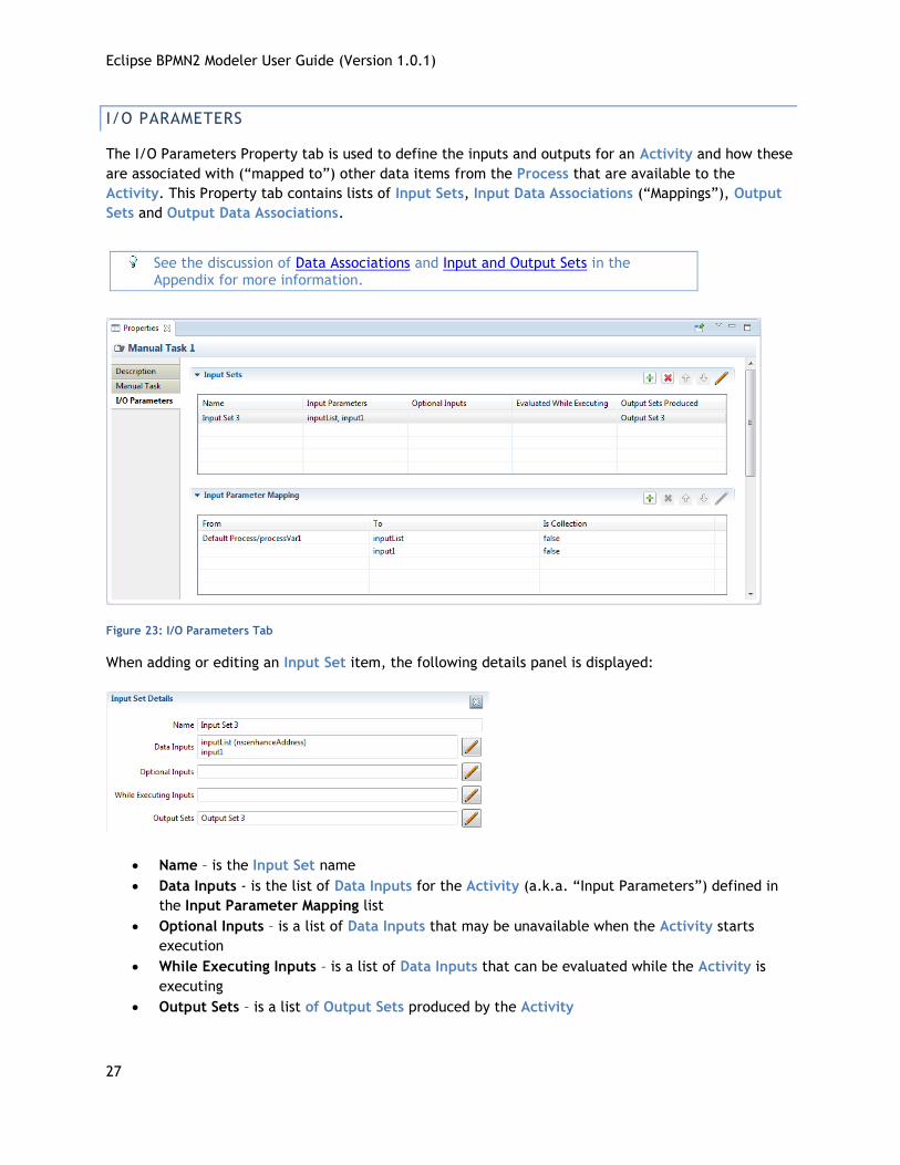
I/O PARAMETERS
The I/O Parameters Property tab is used to define the inputs and outputs for an Activity and how these
are associated with (“mapped to”) other data items from the Process that are available to the
Activity. This Property tab contains lists of Input Sets, Input Data Associations (“Mappings”), Output
Sets and Output Data Associations.
See the discussion of Data Associations and Input and Output Sets in the Appendix for more information.
Figure 23: I/O Parameters Tab
When adding or editing an Input Set item, the following details panel is displayed:
Name – is the Input Set name
Data Inputs - is the list of Data Inputs for the Activity (a.k.a. “Input Parameters”) defined in
the Input Parameter Mapping list
Optional Inputs – is a list of Data Inputs that may be unavailable when the Activity starts
execution
While Executing Inputs – is a list of Data Inputs that can be evaluated while the Activity is
executing
Output Sets – is a list of Output Sets produced by the Activity
Eclipse BPMN2 Modeler User Guide (Version 1.0.1)
28
Input Parameter Mapping determines how the Input Parameters are filled before the Activity is
executed. Similarly, Output Parameter Mapping determines how data is pulled from Output Parameters
after the Activity has finished.
In the following discussion, only the Input Parameter Mapping will be shown; the behavior of Output
Parameter Mapping is similar except that the “From” and “To” directions are reversed.
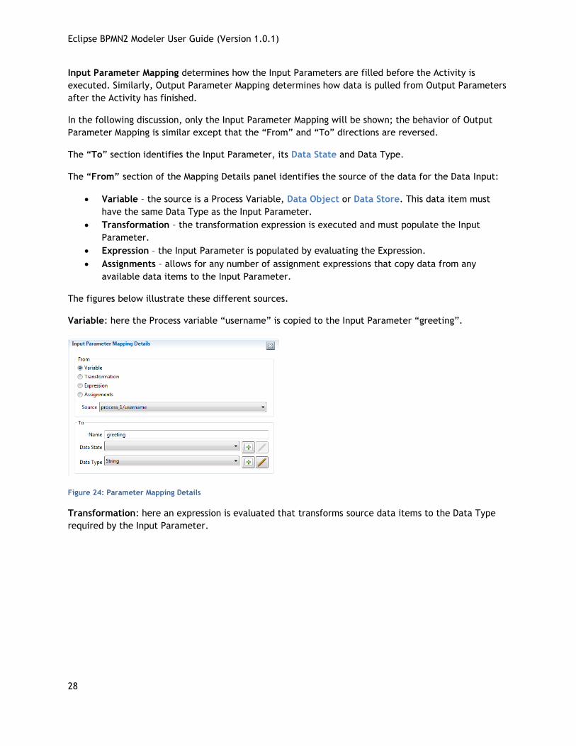
The “To” section identifies the Input Parameter, its Data State and Data Type.
The “From” section of the Mapping Details panel identifies the source of the data for the Data Input:
Variable – the source is a Process Variable, Data Object or Data Store. This data item must
have the same Data Type as the Input Parameter.
Transformation – the transformation expression is executed and must populate the Input
Parameter.
Expression – the Input Parameter is populated by evaluating the Expression.
Assignments – allows for any number of assignment expressions that copy data from any
available data items to the Input Parameter.
The figures below illustrate these different sources.
Variable: here the Process variable “username” is copied to the Input Parameter “greeting”.
Figure 24: Parameter Mapping Details
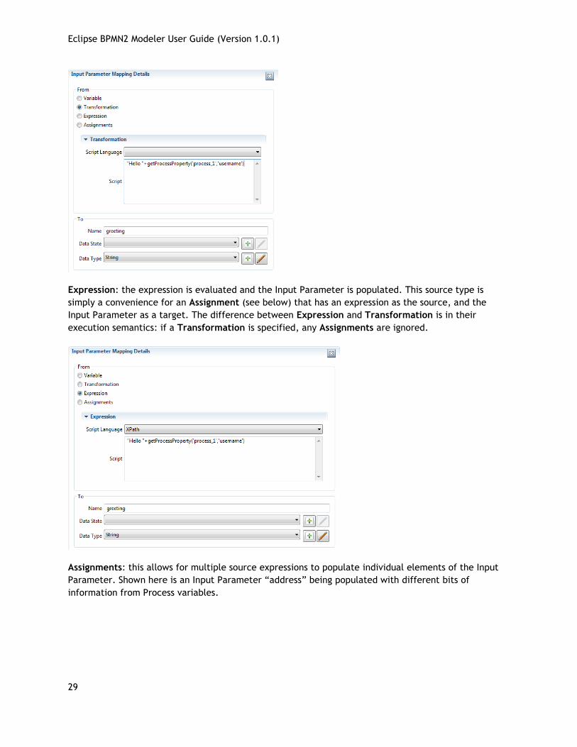
Transformation: here an expression is evaluated that transforms source data items to the Data Type
required by the Input Parameter.
Eclipse BPMN2 Modeler User Guide (Version 1.0.1)
29
Expression: the expression is evaluated and the Input Parameter is populated. This source type is
simply a convenience for an Assignment (see below) that has an expression as the source, and the
Input Parameter as a target. The difference between Expression and Transformation is in their
execution semantics: if a Transformation is specified, any Assignments are ignored.
Assignments: this allows for multiple source expressions to populate individual elements of the Input
Parameter. Shown here is an Input Parameter “address” being populated with different bits of
information from Process variables.
Eclipse BPMN2 Modeler User Guide (Version 1.0.1)
30
The Output Sets and Output Parameter Mapping Lists are similar to their input counterparts, but with
the “from” and “to” directions reversed.
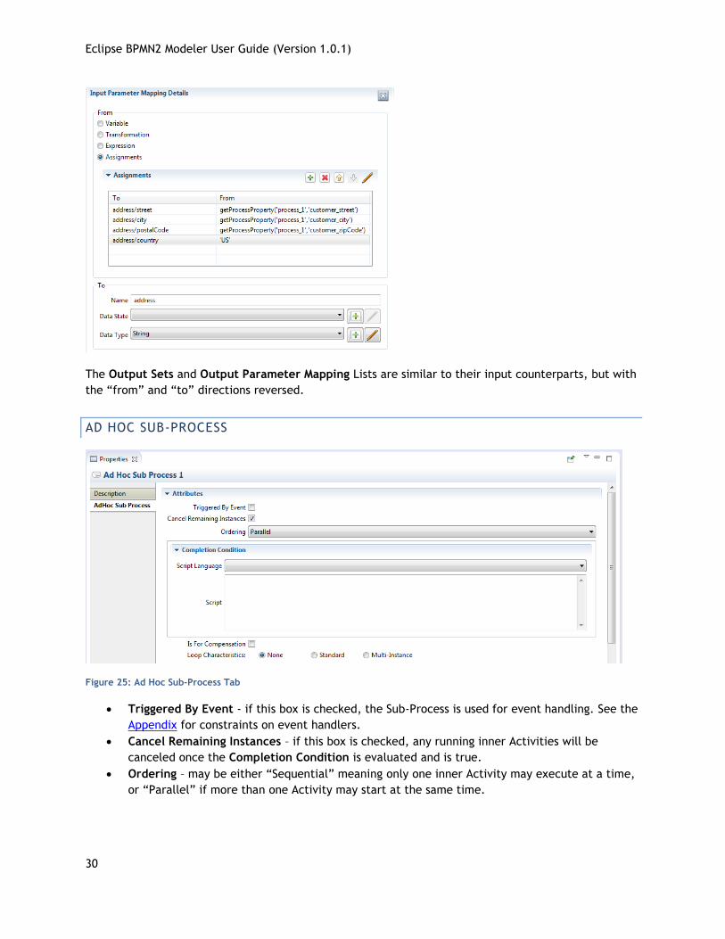
AD HOC SUB-PROCESS
Figure 25: Ad Hoc Sub-Process Tab
Triggered By Event - if this box is checked, the Sub-Process is used for event handling. See the
Appendix for constraints on event handlers.
Cancel Remaining Instances – if this box is checked, any running inner Activities will be
canceled once the Completion Condition is evaluated and is true.
Ordering – may be either “Sequential” meaning only one inner Activity may execute at a time,
or “Parallel” if more than one Activity may start at the same time.
Eclipse BPMN2 Modeler User Guide (Version 1.0.1)
31
Completion Condition – a condition expression that is evaluated after completion of any inner
Activity: if the condition is false, other inner Activities can be executed; if true, the Ad Hoc
Sup-Process completes and no other Activities will be executed.
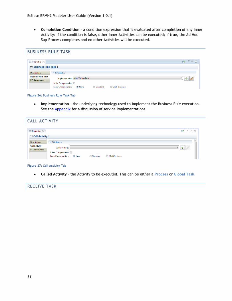
BUSINESS RULE TASK
Figure 26: Business Rule Task Tab
Implementation – the underlying technology used to implement the Business Rule execution.
See the Appendix for a discussion of service implementations.
CALL ACTIVITY
Figure 27: Call Activity Tab
Called Activity – the Activity to be executed. This can be either a Process or Global Task.
RECEIVE TASK
Eclipse BPMN2 Modeler User Guide (Version 1.0.1)
32
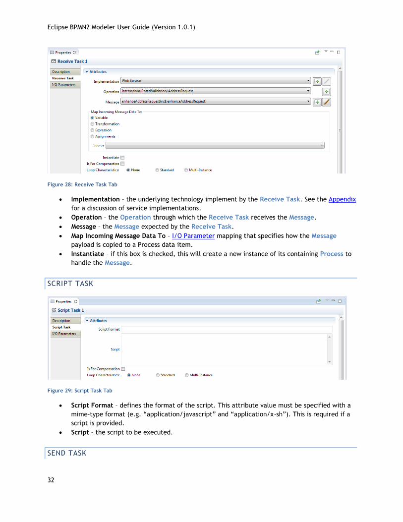
Figure 28: Receive Task Tab
Implementation – the underlying technology implement by the Receive Task. See the Appendix
for a discussion of service implementations.
Operation – the Operation through which the Receive Task receives the Message.
Message – the Message expected by the Receive Task.
Map Incoming Message Data To – I/O Parameter mapping that specifies how the Message
payload is copied to a Process data item.
Instantiate – if this box is checked, this will create a new instance of its containing Process to
handle the Message.
SCRIPT TASK
Figure 29: Script Task Tab
Script Format – defines the format of the script. This attribute value must be specified with a
mime-type format (e.g. “application/javascript” and “application/x-sh”). This is required if a
script is provided.
Script – the script to be executed.
SEND TASK
Eclipse BPMN2 Modeler User Guide (Version 1.0.1)
33
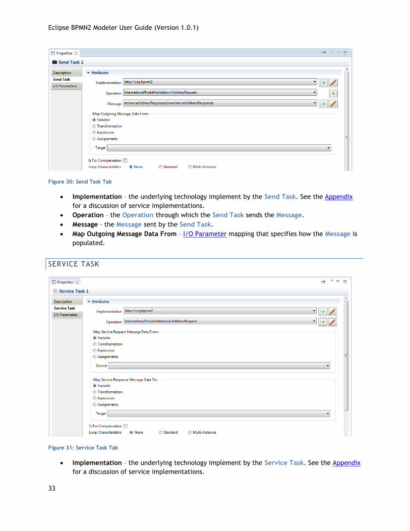
Figure 30: Send Task Tab
Implementation – the underlying technology implement by the Send Task. See the Appendix
for a discussion of service implementations.
Operation – the Operation through which the Send Task sends the Message.
Message – the Message sent by the Send Task.
Map Outgoing Message Data From – I/O Parameter mapping that specifies how the Message is
populated.
SERVICE TASK
Figure 31: Service Task Tab
Implementation – the underlying technology implement by the Service Task. See the Appendix
for a discussion of service implementations.
Eclipse BPMN2 Modeler User Guide (Version 1.0.1)
34
Operation – the Operation through which the Send Task sends the Message.
Map Service Request Message Data From – I/O Parameter mapping that specifies how the
service request Message is populated.
Map Service Response Message Data To – I/O Parameter mapping that specifies how the
service response Message payload is copied back into the Process as, e.g. a Data Object,
Process Variable, etc.
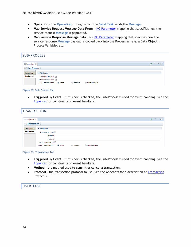
SUB-PROCESS
Figure 32: Sub-Process Tab
Triggered By Event - if this box is checked, the Sub-Process is used for event handling. See the
Appendix for constraints on event handlers.
TRANSACTION
Figure 33: Transaction Tab
Triggered By Event - if this box is checked, the Sub-Process is used for event handling. See the
Appendix for constraints on event handlers.
Method - the method used to commit or cancel a transaction.
Protocol - the transaction protocol to use. See the Appendix for a description of Transaction
Protocols.
USER TASK
Eclipse BPMN2 Modeler User Guide (Version 1.0.1)
35
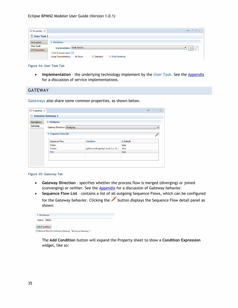
Figure 34: User Task Tab
Implementation – the underlying technology implement by the User Task. See the Appendix
for a discussion of service implementations.
GATEWAY
Gateways also share some common properties, as shown below.
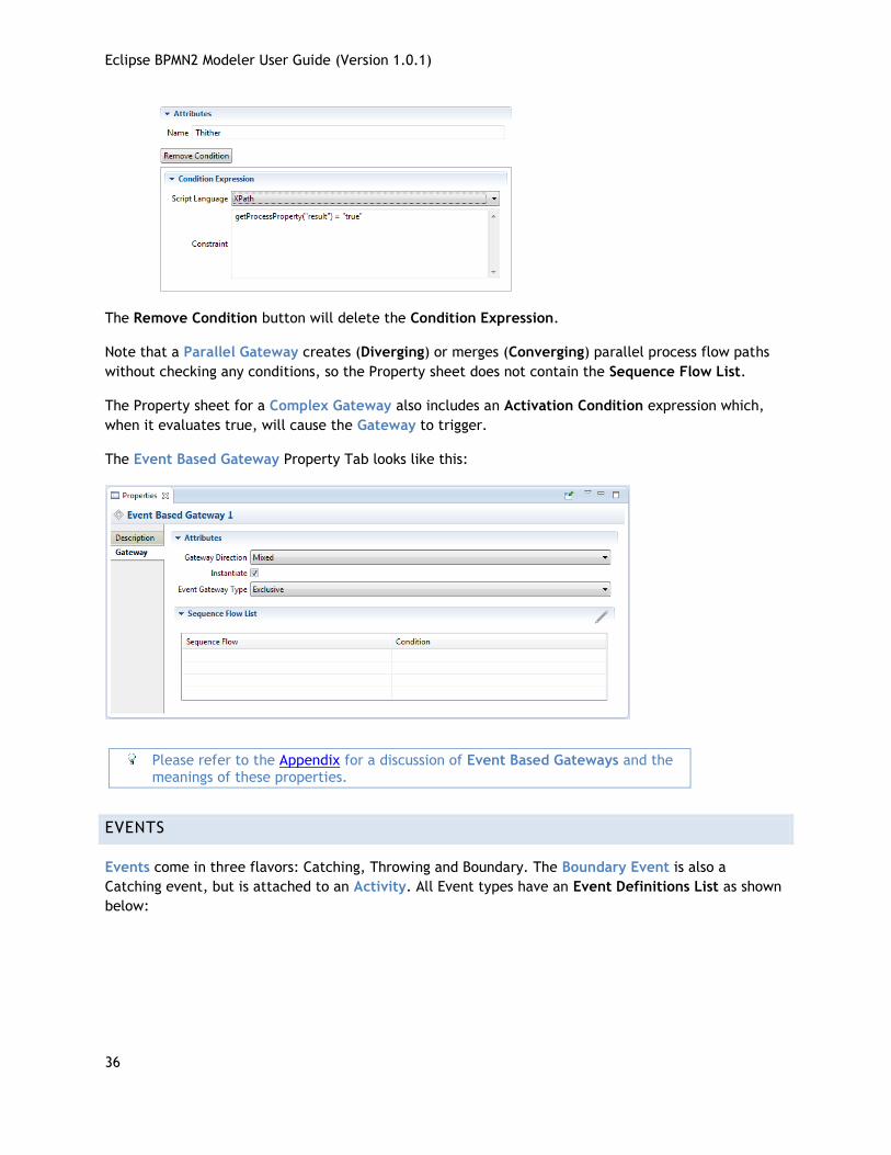
Figure 35: Gateway Tab
Gateway Direction – specifies whether the process flow is merged (diverging) or joined
(converging) or neither. See the Appendix for a discussion of Gateway behavior.
Sequence Flow List – contains a list of all outgoing Sequence Flows, which can be configured
for the Gateway behavior. Clicking the button displays the Sequence Flow detail panel as
shown:
The Add Condition button will expand the Property sheet to show a Condition Expression
widget, like so:
Eclipse BPMN2 Modeler User Guide (Version 1.0.1)
36
The Remove Condition button will delete the Condition Expression.
Note that a Parallel Gateway creates (Diverging) or merges (Converging) parallel process flow paths
without checking any conditions, so the Property sheet does not contain the Sequence Flow List.
The Property sheet for a Complex Gateway also includes an Activation Condition expression which,
when it evaluates true, will cause the Gateway to trigger.
The Event Based Gateway Property Tab looks like this:
Please refer to the Appendix for a discussion of Event Based Gateways and the meanings of these properties.
EVENTS
Events come in three flavors: Catching, Throwing and Boundary. The Boundary Event is also a
Catching event, but is attached to an Activity. All Event types have an Event Definitions List as shown
below:
Eclipse BPMN2 Modeler User Guide (Version 1.0.1)
37
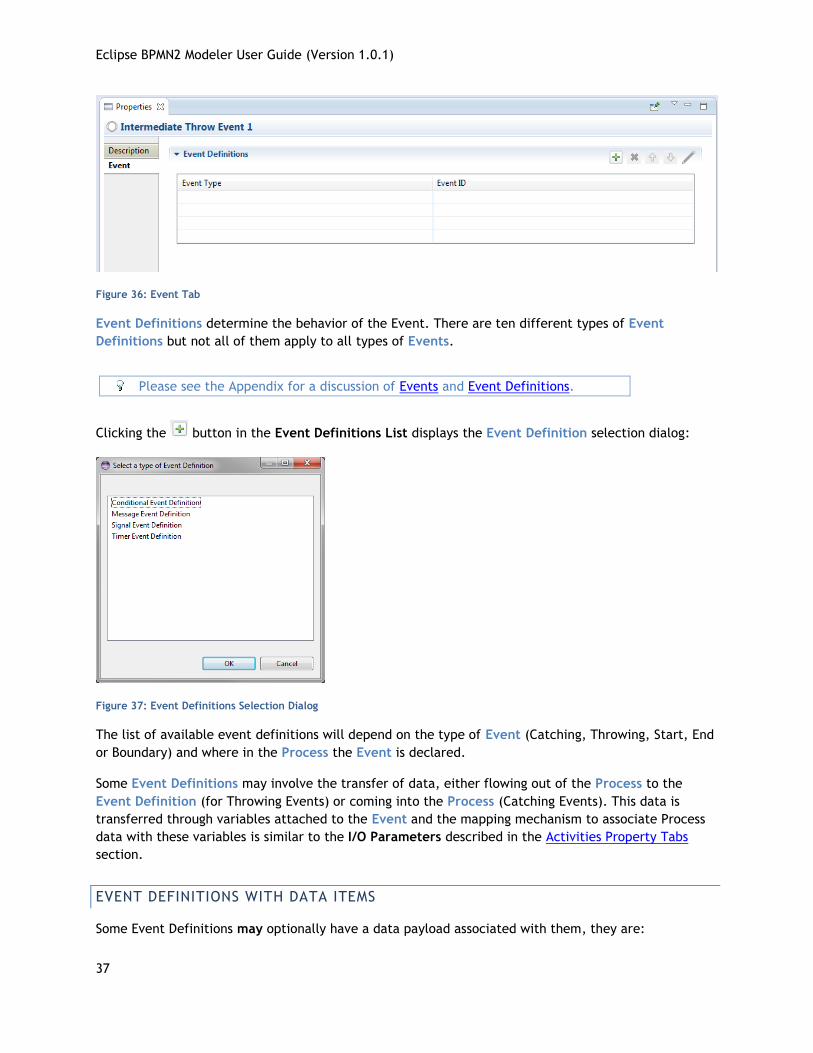
Figure 36: Event Tab
Event Definitions determine the behavior of the Event. There are ten different types of Event
Definitions but not all of them apply to all types of Events.
Please see the Appendix for a discussion of Events and Event Definitions.
Clicking the button in the Event Definitions List displays the Event Definition selection dialog:
Figure 37: Event Definitions Selection Dialog
The list of available event definitions will depend on the type of Event (Catching, Throwing, Start, End
or Boundary) and where in the Process the Event is declared.
Some Event Definitions may involve the transfer of data, either flowing out of the Process to the
Event Definition (for Throwing Events) or coming into the Process (Catching Events). This data is
transferred through variables attached to the Event and the mapping mechanism to associate Process
data with these variables is similar to the I/O Parameters described in the Activities Property Tabs
section.
EVENT DEFINITIONS WITH DATA ITEMS
Some Event Definitions may optionally have a data payload associated with them, they are:
Eclipse BPMN2 Modeler User Guide (Version 1.0.1)
38
Error
Escalation
Message
Signal
ERROR EVENT DEFINITION
The Details panel for an Error Event Defintion looks like this:
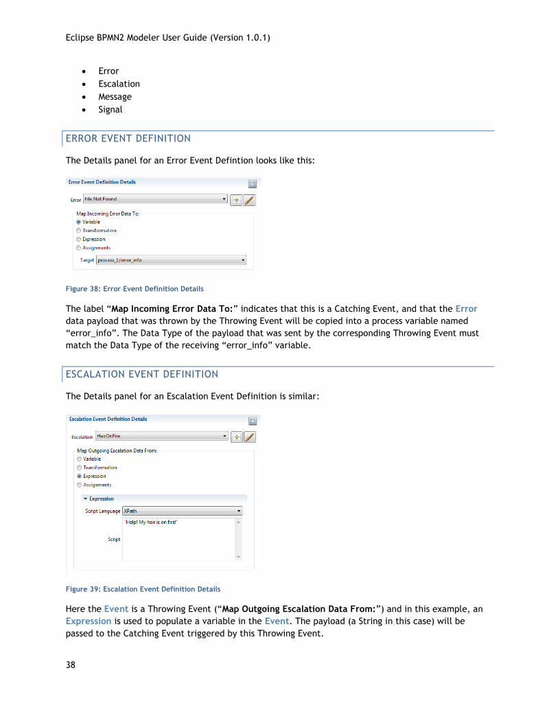
Figure 38: Error Event Definition Details
The label “Map Incoming Error Data To:” indicates that this is a Catching Event, and that the Error
data payload that was thrown by the Throwing Event will be copied into a process variable named
“error_info”. The Data Type of the payload that was sent by the corresponding Throwing Event must
match the Data Type of the receiving “error_info” variable.
ESCALATION EVENT DEFINITION
The Details panel for an Escalation Event Definition is similar:
Figure 39: Escalation Event Definition Details
Here the Event is a Throwing Event (“Map Outgoing Escalation Data From:”) and in this example, an
Expression is used to populate a variable in the Event. The payload (a String in this case) will be
passed to the Catching Event triggered by this Throwing Event.
Eclipse BPMN2 Modeler User Guide (Version 1.0.1)
39
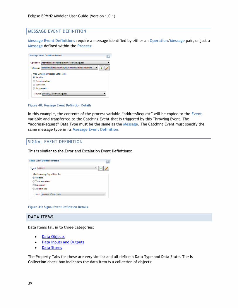
MESSAGE EVENT DEFINITION
Message Event Definitions require a message identified by either an Operation/Message pair, or just a
Message defined within the Process:
Figure 40: Message Event Definition Details
In this example, the contents of the process variable “addressRequest” will be copied to the Event
variable and transferred to the Catching Event that is triggered by this Throwing Event. The
“addressRequest” Data Type must be the same as the Message. The Catching Event must specify the
same message type in its Message Event Definition.
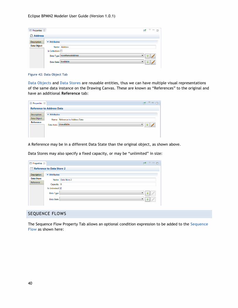
SIGNAL EVENT DEFINITION
This is similar to the Error and Escalation Event Definitions:
Figure 41: Signal Event Definition Details
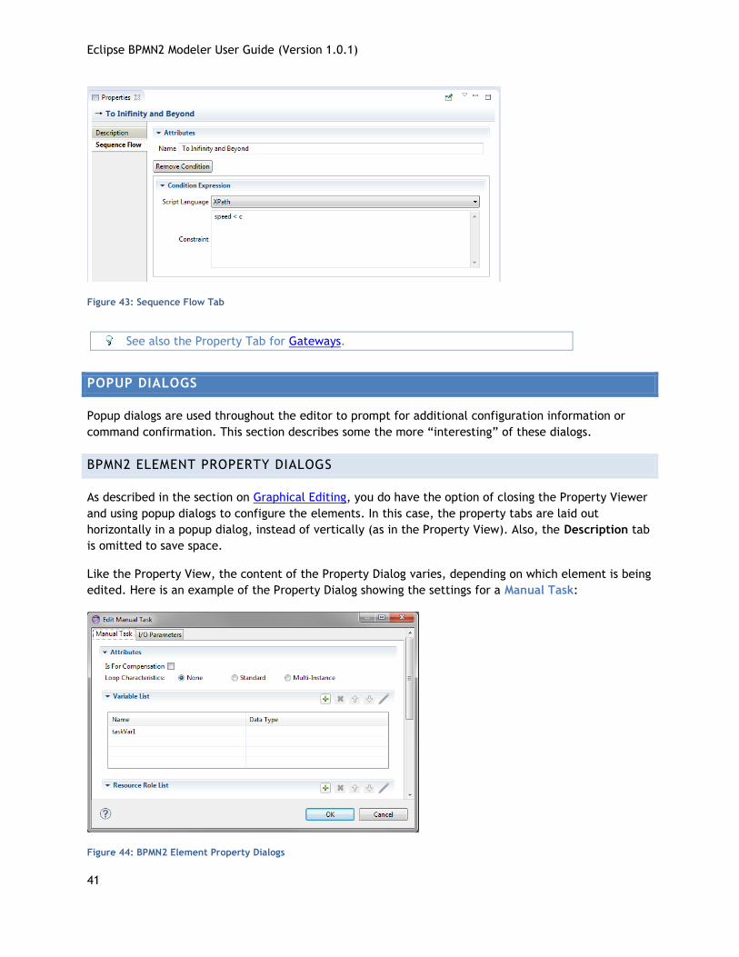
DATA ITEMS
Data Items fall in to three categories:
Data Objects
Data Inputs and Outputs
Data Stores
The Property Tabs for these are very similar and all define a Data Type and Data State. The Is
Collection check box indicates the data item is a collection of objects:
Eclipse BPMN2 Modeler User Guide (Version 1.0.1)
40
Figure 42: Data Object Tab
Data Objects and Data Stores are reusable entities, thus we can have multiple visual representations
of the same data instance on the Drawing Canvas. These are known as “References” to the original and
have an additional Reference tab:
A Reference may be in a different Data State than the original object, as shown above.
Data Stores may also specify a fixed capacity, or may be “unlimited” in size:
SEQUENCE FLOWS
The Sequence Flow Property Tab allows an optional condition expression to be added to the Sequence
Flow as shown here:
Eclipse BPMN2 Modeler User Guide (Version 1.0.1)
41
Figure 43: Sequence Flow Tab
See also the Property Tab for Gateways.
POPUP DIALOGS
Popup dialogs are used throughout the editor to prompt for additional configuration information or
command confirmation. This section describes some the more “interesting” of these dialogs.
BPMN2 ELEMENT PROPERTY DIALOGS
As described in the section on Graphical Editing, you do have the option of closing the Property Viewer
and using popup dialogs to configure the elements. In this case, the property tabs are laid out
horizontally in a popup dialog, instead of vertically (as in the Property View). Also, the Description tab
is omitted to save space.
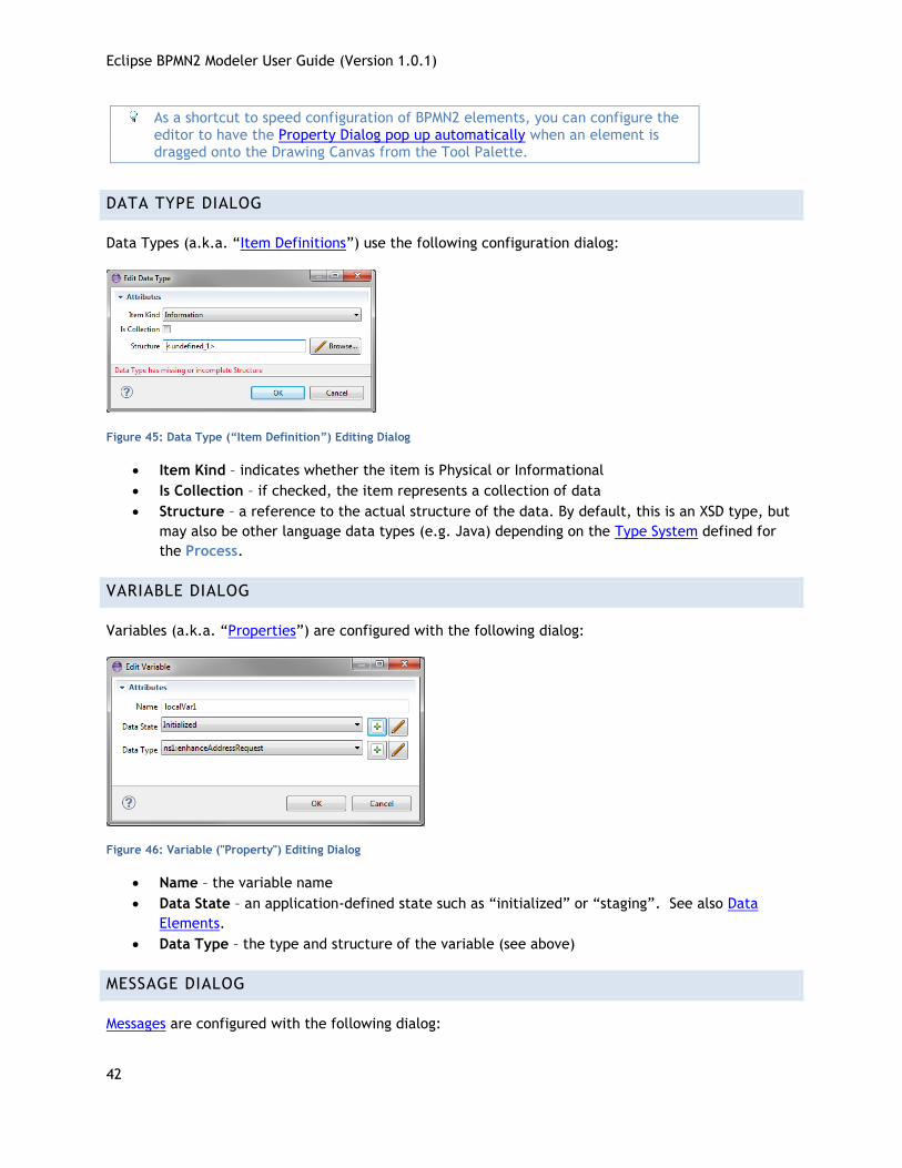
Like the Property View, the content of the Property Dialog varies, depending on which element is being
edited. Here is an example of the Property Dialog showing the settings for a Manual Task:
Figure 44: BPMN2 Element Property Dialogs
Eclipse BPMN2 Modeler User Guide (Version 1.0.1)
42
As a shortcut to speed configuration of BPMN2 elements, you can configure the editor to have the Property Dialog pop up automatically when an element is dragged onto the Drawing Canvas from the Tool Palette.
DATA TYPE DIALOG
Data Types (a.k.a. “Item Definitions”) use the following configuration dialog:
Figure 45: Data Type (“Item Definition”) Editing Dialog
Item Kind – indicates whether the item is Physical or Informational
Is Collection – if checked, the item represents a collection of data
Structure – a reference to the actual structure of the data. By default, this is an XSD type, but
may also be other language data types (e.g. Java) depending on the Type System defined for
the Process.
VARIABLE DIALOG
Variables (a.k.a. “Properties”) are configured with the following dialog:
Figure 46: Variable ("Property") Editing Dialog
Name – the variable name
Data State – an application-defined state such as “initialized” or “staging”. See also Data
Elements.
Data Type – the type and structure of the variable (see above)
MESSAGE DIALOG
Messages are configured with the following dialog:
Eclipse BPMN2 Modeler User Guide (Version 1.0.1)
43
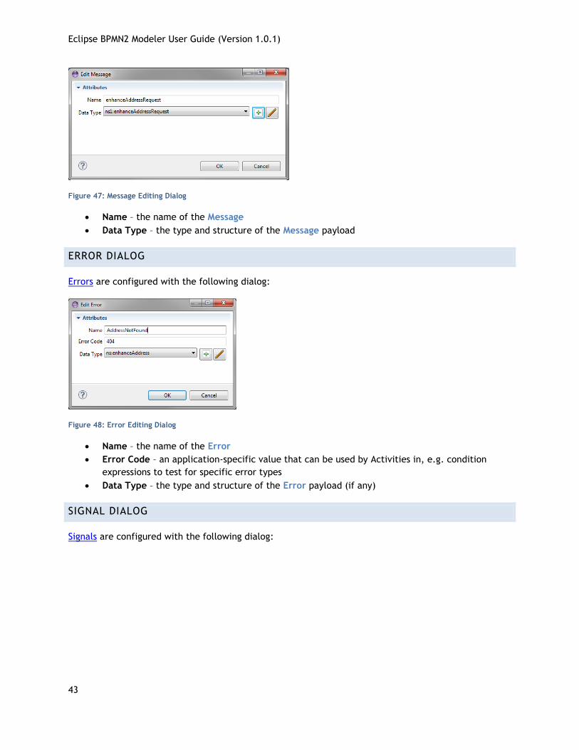
Figure 47: Message Editing Dialog
Name – the name of the Message
Data Type – the type and structure of the Message payload
ERROR DIALOG
Errors are configured with the following dialog:
Figure 48: Error Editing Dialog
Name – the name of the Error
Error Code – an application-specific value that can be used by Activities in, e.g. condition
expressions to test for specific error types
Data Type – the type and structure of the Error payload (if any)
SIGNAL DIALOG
Signals are configured with the following dialog:
Eclipse BPMN2 Modeler User Guide (Version 1.0.1)
44
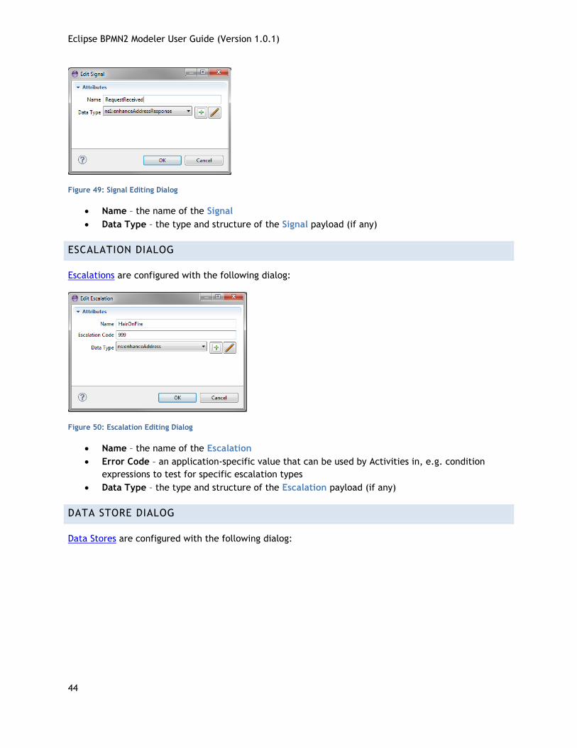
Figure 49: Signal Editing Dialog
Name – the name of the Signal
Data Type – the type and structure of the Signal payload (if any)
ESCALATION DIALOG
Escalations are configured with the following dialog:
Figure 50: Escalation Editing Dialog
Name – the name of the Escalation
Error Code – an application-specific value that can be used by Activities in, e.g. condition
expressions to test for specific escalation types
Data Type – the type and structure of the Escalation payload (if any)
DATA STORE DIALOG
Data Stores are configured with the following dialog:
Eclipse BPMN2 Modeler User Guide (Version 1.0.1)
45
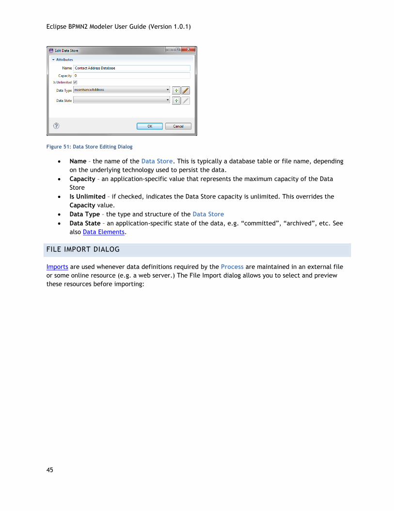
Figure 51: Data Store Editing Dialog
Name – the name of the Data Store. This is typically a database table or file name, depending
on the underlying technology used to persist the data.
Capacity – an application-specific value that represents the maximum capacity of the Data
Store
Is Unlimited – if checked, indicates the Data Store capacity is unlimited. This overrides the
Capacity value.
Data Type – the type and structure of the Data Store
Data State – an application-specific state of the data, e.g. “committed”, “archived”, etc. See
also Data Elements.
FILE IMPORT DIALOG
Imports are used whenever data definitions required by the Process are maintained in an external file
or some online resource (e.g. a web server.) The File Import dialog allows you to select and preview
these resources before importing:
Eclipse BPMN2 Modeler User Guide (Version 1.0.1)
46
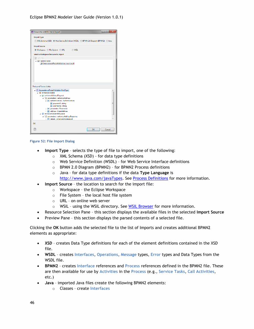
Figure 52: File Import Dialog
Import Type – selects the type of file to import, one of the following:
o XML Schema (XSD) - for data type definitions
o Web Service Definition (WSDL) – for Web Service Interface definitions
o BPMN 2.0 Diagram (BPMN2) – for BPMN2 Process definitions
o Java – for data type definitions if the data Type Language is
http://www.java.com/javaTypes. See Process Definitions for more information.
Import Source – the location to search for the import file:
o Workspace – the Eclipse Workspace
o File System – the local host file system
o URL – on online web server
o WSIL – using the WSIL directory. See WSIL Browser for more information.
Resource Selection Pane – this section displays the available files in the selected Import Source
Preview Pane – this section displays the parsed contents of a selected file.
Clicking the OK button adds the selected file to the list of Imports and creates additional BPMN2
elements as appropriate:
XSD – creates Data Type definitions for each of the element definitions contained in the XSD
file.
WSDL – creates Interfaces, Operations, Message types, Error types and Data Types from the
WSDL file.
BPMN2 – creates Interface references and Process references defined in the BPMN2 file. These
are then available for use by Activities in the Process (e.g., Service Tasks, Call Activities,
etc.)
Java – imported Java files create the following BPMN2 elements:
o Classes – create Interfaces
Eclipse BPMN2 Modeler User Guide (Version 1.0.1)
47
o Class methods – create Operations for these Interfaces
o Method Parameters – create Messages and Data Types for each of the parameters
o Method return values – create Messages and Data Types
o Method “throw” declarations create Errors and Data Types for the Java Exception
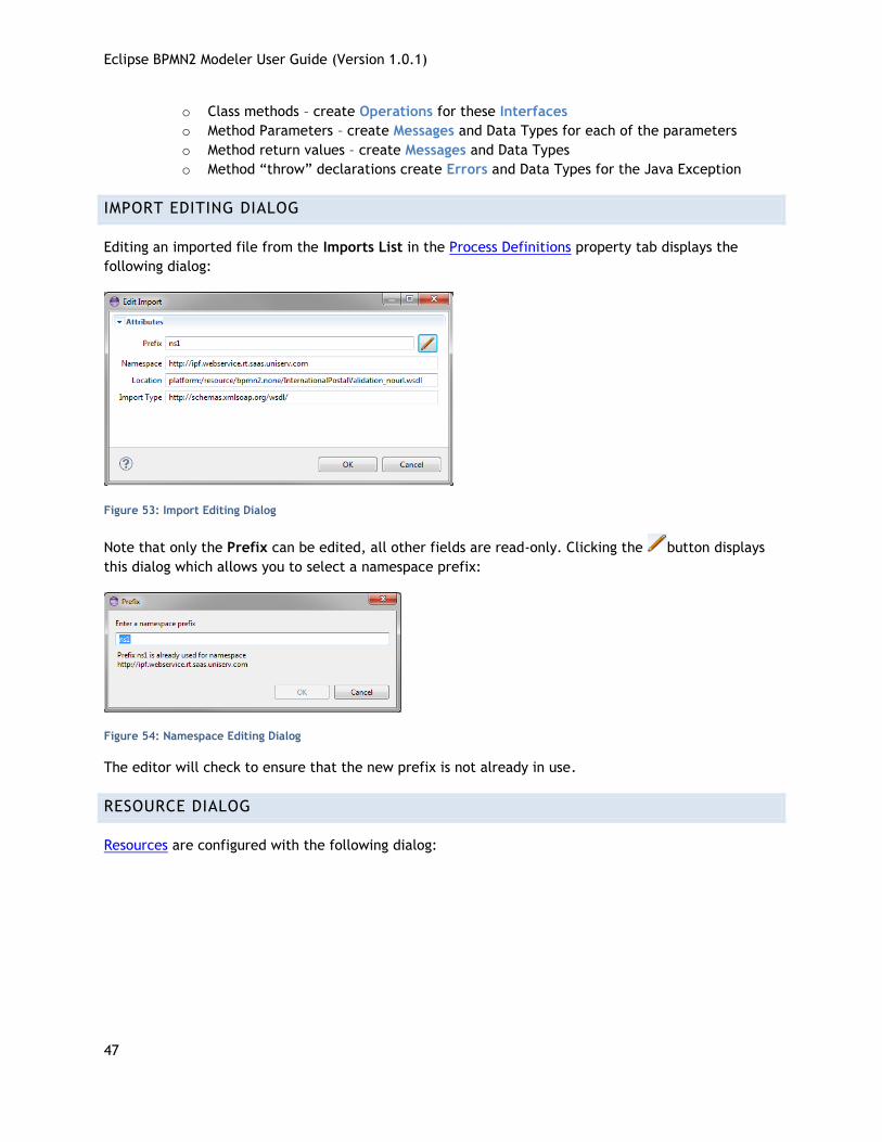
IMPORT EDITING DIALOG
Editing an imported file from the Imports List in the Process Definitions property tab displays the
following dialog:
Figure 53: Import Editing Dialog
Note that only the Prefix can be edited, all other fields are read-only. Clicking the button displays
this dialog which allows you to select a namespace prefix:
Figure 54: Namespace Editing Dialog
The editor will check to ensure that the new prefix is not already in use.
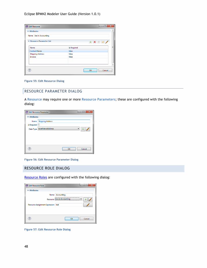
RESOURCE DIALOG
Resources are configured with the following dialog:
Eclipse BPMN2 Modeler User Guide (Version 1.0.1)
48
Figure 55: Edit Resource Dialog
RESOURCE PARAMETER DIALOG
A Resource may require one or more Resource Parameters; these are configured with the following
dialog:
Figure 56: Edit Resource Parameter Dialog
RESOURCE ROLE DIALOG
Resource Roles are configured with the following dialog:
Figure 57: Edit Resource Role Dialog
Eclipse BPMN2 Modeler User Guide (Version 1.0.1)
49
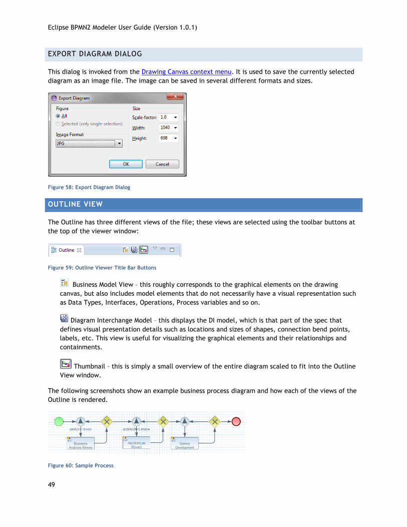
EXPORT DIAGRAM DIALOG
This dialog is invoked from the Drawing Canvas context menu. It is used to save the currently selected
diagram as an image file. The image can be saved in several different formats and sizes.
Figure 58: Export Diagram Dialog
OUTLINE VIEW
The Outline has three different views of the file; these views are selected using the toolbar buttons at
the top of the viewer window:
Figure 59: Outline Viewer Title Bar Buttons
Business Model View – this roughly corresponds to the graphical elements on the drawing
canvas, but also includes model elements that do not necessarily have a visual representation such
as Data Types, Interfaces, Operations, Process variables and so on.
Diagram Interchange Model – this displays the DI model, which is that part of the spec that
defines visual presentation details such as locations and sizes of shapes, connection bend points,
labels, etc. This view is useful for visualizing the graphical elements and their relationships and
containments.
Thumbnail – this is simply a small overview of the entire diagram scaled to fit into the Outline
View window.
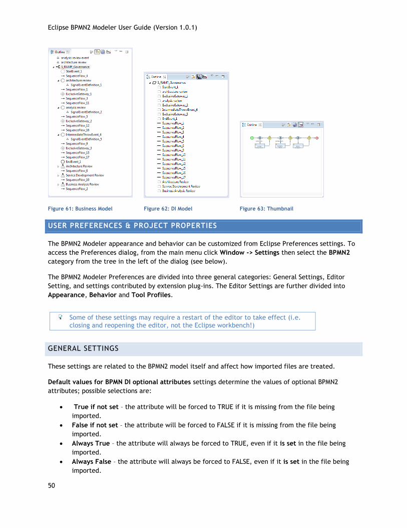
The following screenshots show an example business process diagram and how each of the views of the
Outline is rendered.
Figure 60: Sample Process
Eclipse BPMN2 Modeler User Guide (Version 1.0.1)
50
Figure 61: Business Model Figure 62: DI Model Figure 63: Thumbnail
USER PREFERENCES & PROJECT PROPERTIES
The BPMN2 Modeler appearance and behavior can be customized from Eclipse Preferences settings. To
access the Preferences dialog, from the main menu click Window -> Settings then select the BPMN2
category from the tree in the left of the dialog (see below).
The BPMN2 Modeler Preferences are divided into three general categories: General Settings, Editor
Setting, and settings contributed by extension plug-ins. The Editor Settings are further divided into
Appearance, Behavior and Tool Profiles.
Some of these settings may require a restart of the editor to take effect (i.e.
closing and reopening the editor, not the Eclipse workbench!)
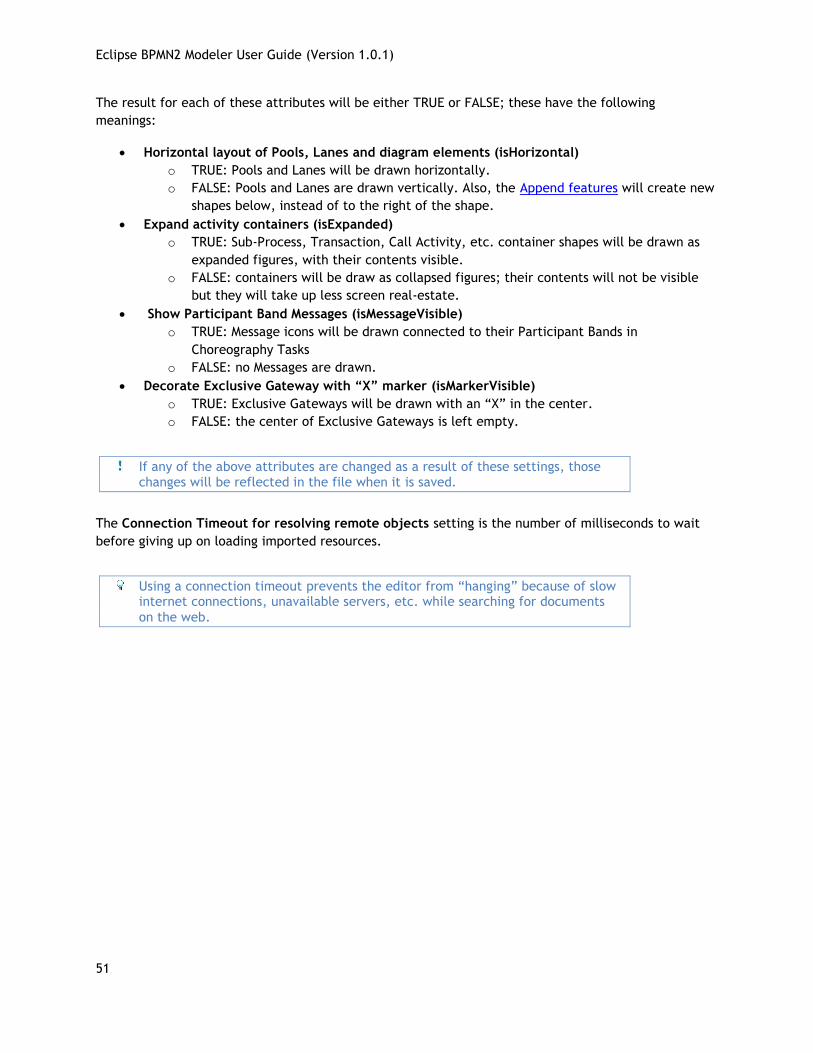
GENERAL SETTINGS
These settings are related to the BPMN2 model itself and affect how imported files are treated.
Default values for BPMN DI optional attributes settings determine the values of optional BPMN2
attributes; possible selections are:
True if not set – the attribute will be forced to TRUE if it is missing from the file being
imported.
False if not set – the attribute will be forced to FALSE if it is missing from the file being
imported.
Always True – the attribute will always be forced to TRUE, even if it is set in the file being
imported.
Always False – the attribute will always be forced to FALSE, even if it is set in the file being
imported.
Eclipse BPMN2 Modeler User Guide (Version 1.0.1)
51
The result for each of these attributes will be either TRUE or FALSE; these have the following
meanings:
Horizontal layout of Pools, Lanes and diagram elements (isHorizontal)
o TRUE: Pools and Lanes will be drawn horizontally.
o FALSE: Pools and Lanes are drawn vertically. Also, the Append features will create new
shapes below, instead of to the right of the shape.
Expand activity containers (isExpanded)
o TRUE: Sub-Process, Transaction, Call Activity, etc. container shapes will be drawn as
expanded figures, with their contents visible.
o FALSE: containers will be draw as collapsed figures; their contents will not be visible
but they will take up less screen real-estate.
Show Participant Band Messages (isMessageVisible)
o TRUE: Message icons will be drawn connected to their Participant Bands in
Choreography Tasks
o FALSE: no Messages are drawn.
Decorate Exclusive Gateway with “X” marker (isMarkerVisible)
o TRUE: Exclusive Gateways will be drawn with an “X” in the center.
o FALSE: the center of Exclusive Gateways is left empty.
If any of the above attributes are changed as a result of these settings, those changes will be reflected in the file when it is saved.
The Connection Timeout for resolving remote objects setting is the number of milliseconds to wait
before giving up on loading imported resources.
Using a connection timeout prevents the editor from “hanging” because of slow internet connections, unavailable servers, etc. while searching for documents
on the web.
Eclipse BPMN2 Modeler User Guide (Version 1.0.1)
52
Figure 64: BPMN2 General Settings
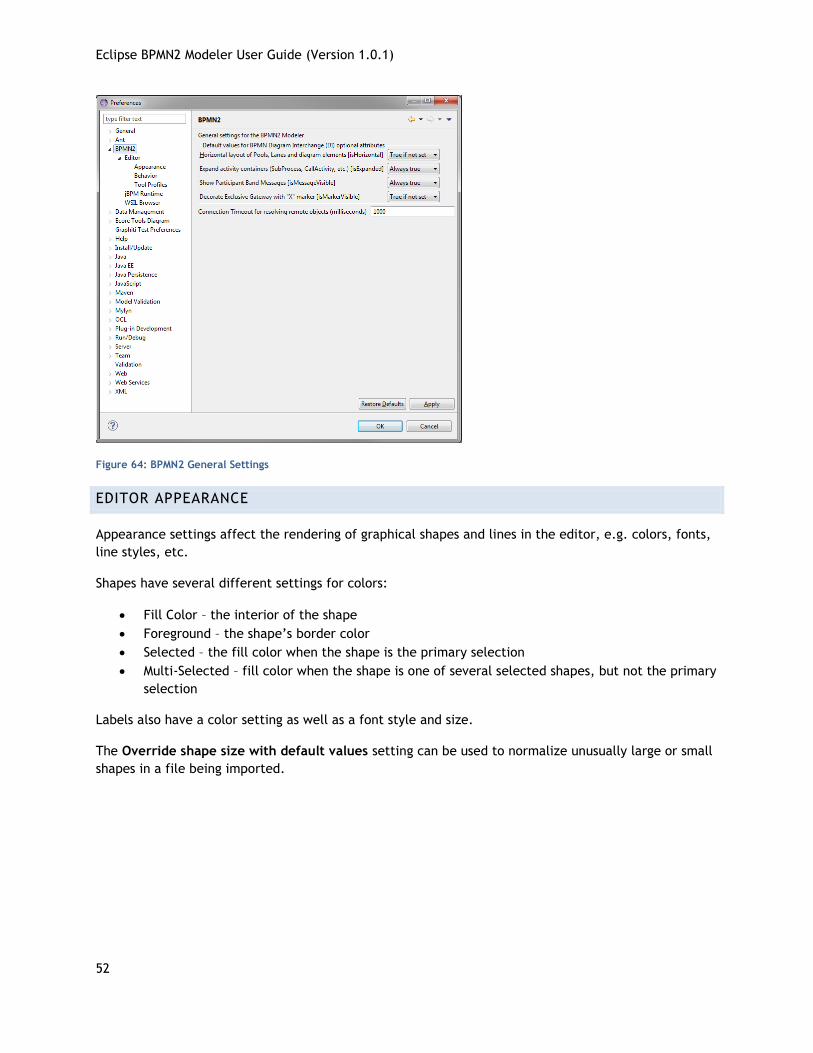
EDITOR APPEARANCE
Appearance settings affect the rendering of graphical shapes and lines in the editor, e.g. colors, fonts,
line styles, etc.
Shapes have several different settings for colors:
Fill Color – the interior of the shape
Foreground – the shape’s border color
Selected – the fill color when the shape is the primary selection
Multi-Selected – fill color when the shape is one of several selected shapes, but not the primary
selection
Labels also have a color setting as well as a font style and size.
The Override shape size with default values setting can be used to normalize unusually large or small
shapes in a file being imported.
Eclipse BPMN2 Modeler User Guide (Version 1.0.1)
53
Figure 65: Editor Appearance (Shapes)
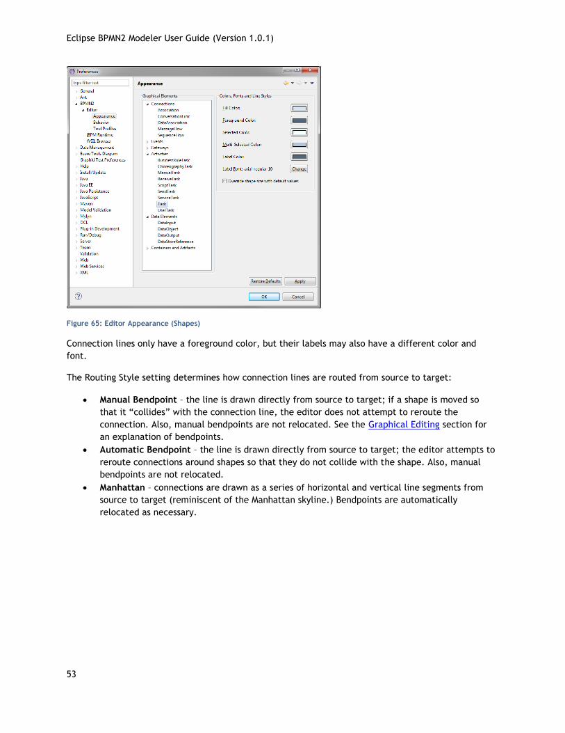
Connection lines only have a foreground color, but their labels may also have a different color and
font.
The Routing Style setting determines how connection lines are routed from source to target:
Manual Bendpoint – the line is drawn directly from source to target; if a shape is moved so
that it “collides” with the connection line, the editor does not attempt to reroute the
connection. Also, manual bendpoints are not relocated. See the Graphical Editing section for
an explanation of bendpoints.
Automatic Bendpoint – the line is drawn directly from source to target; the editor attempts to
reroute connections around shapes so that they do not collide with the shape. Also, manual
bendpoints are not relocated.
Manhattan – connections are drawn as a series of horizontal and vertical line segments from
source to target (reminiscent of the Manhattan skyline.) Bendpoints are automatically
relocated as necessary.
Eclipse BPMN2 Modeler User Guide (Version 1.0.1)
54
Figure 66: Editor Appearance (Connections)
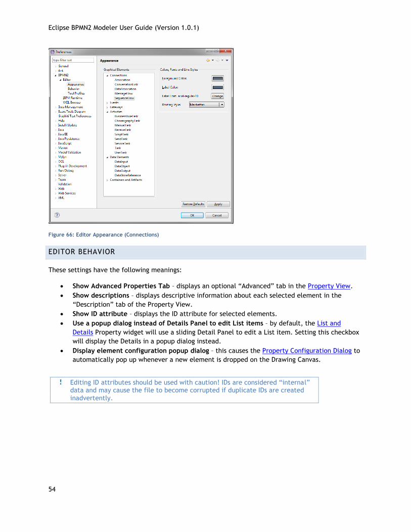
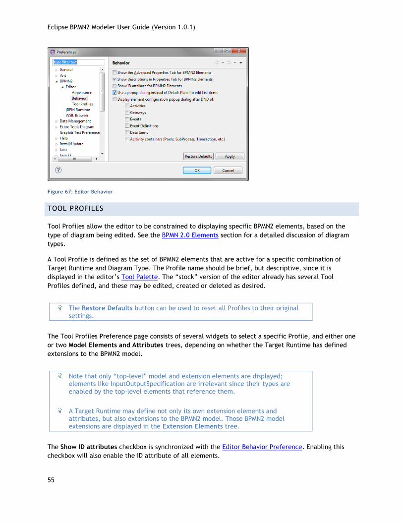
EDITOR BEHAVIOR
These settings have the following meanings:
Show Advanced Properties Tab – displays an optional “Advanced” tab in the Property View.
Show descriptions – displays descriptive information about each selected element in the
“Description” tab of the Property View.
Show ID attribute – displays the ID attribute for selected elements.
Use a popup dialog instead of Details Panel to edit List items – by default, the List and
Details Property widget will use a sliding Detail Panel to edit a List item. Setting this checkbox
will display the Details in a popup dialog instead.
Display element configuration popup dialog – this causes the Property Configuration Dialog to
automatically pop up whenever a new element is dropped on the Drawing Canvas.
Editing ID attributes should be used with caution! IDs are considered “internal” data and may cause the file to become corrupted if duplicate IDs are created
inadvertently.
Eclipse BPMN2 Modeler User Guide (Version 1.0.1)
55
Figure 67: Editor Behavior
TOOL PROFILES
Tool Profiles allow the editor to be constrained to displaying specific BPMN2 elements, based on the
type of diagram being edited. See the BPMN 2.0 Elements section for a detailed discussion of diagram
types.
A Tool Profile is defined as the set of BPMN2 elements that are active for a specific combination of
Target Runtime and Diagram Type. The Profile name should be brief, but descriptive, since it is
displayed in the editor’s Tool Palette. The “stock” version of the editor already has several Tool
Profiles defined, and these may be edited, created or deleted as desired.
The Restore Defaults button can be used to reset all Profiles to their original
settings.
The Tool Profiles Preference page consists of several widgets to select a specific Profile, and either one
or two Model Elements and Attributes trees, depending on whether the Target Runtime has defined
extensions to the BPMN2 model.
Note that only “top-level” model and extension elements are displayed; elements like InputOutputSpecification are irrelevant since their types are enabled by the top-level elements that reference them.
A Target Runtime may define not only its own extension elements and attributes, but also extensions to the BPMN2 model. Those BPMN2 model extensions are displayed in the Extension Elements tree.
The Show ID attributes checkbox is synchronized with the Editor Behavior Preference. Enabling this
checkbox will also enable the ID attribute of all elements.
Eclipse BPMN2 Modeler User Guide (Version 1.0.1)
56
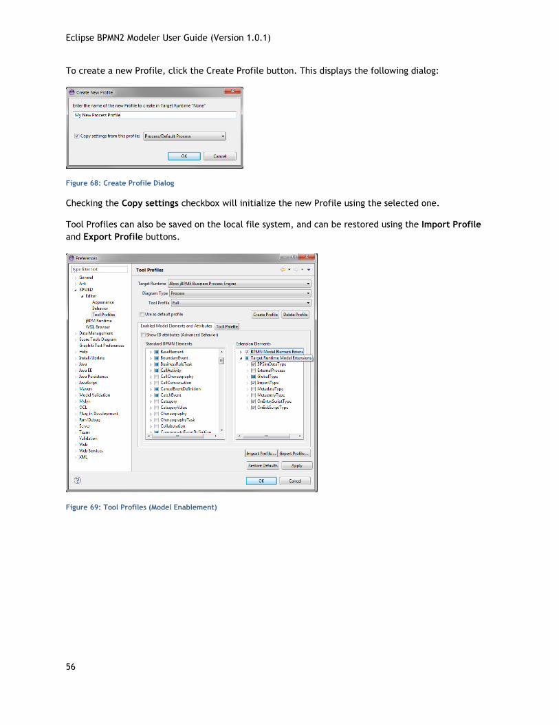
To create a new Profile, click the Create Profile button. This displays the following dialog:
Figure 68: Create Profile Dialog
Checking the Copy settings checkbox will initialize the new Profile using the selected one.
Tool Profiles can also be saved on the local file system, and can be restored using the Import Profile
and Export Profile buttons.
Figure 69: Tool Profiles (Model Enablement)
Eclipse BPMN2 Modeler User Guide (Version 1.0.1)
57
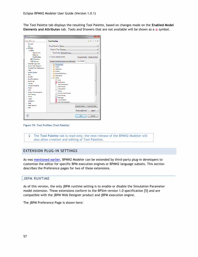
The Tool Palette tab displays the resulting Tool Palette, based on changes made on the Enabled Model
Elements and Attributes tab. Tools and Drawers that are not available will be shown as a symbol.
Figure 70: Tool Profiles (Tool Palette)
The Tool Palette tab is read-only; the next release of the BPMN2 Modeler will also allow creation and editing of Tool Palettes.
EXTENSION PLUG-IN SETTINGS
As was mentioned earlier, BPMN2 Modeler can be extended by third-party plug-in developers to
customize the editor for specific BPM execution engines or BPMN2 language subsets. This section
describes the Preference pages for two of these extensions.
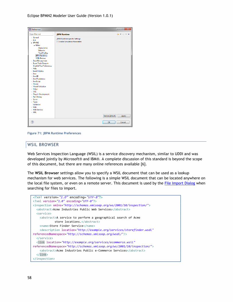
JBPM RUNTIME
As of this version, the only jBPM runtime setting is to enable or disable the Simulation Parameter
model extension. These extensions conform to the BPSim version 1.0 specification [5] and are
compatible with the jBPM Web Designer product and jBPM execution engine.
The jBPM Preference Page is shown here:
Eclipse BPMN2 Modeler User Guide (Version 1.0.1)
58
Figure 71: jBPM Runtime Preferences
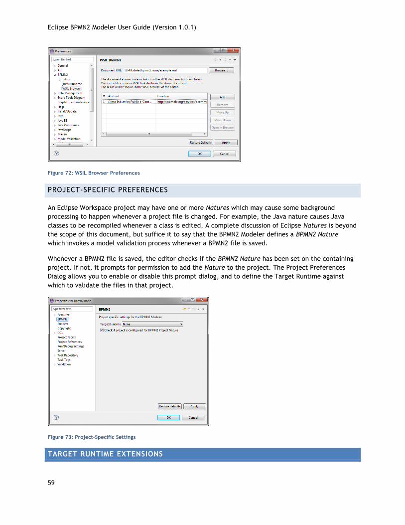
WSIL BROWSER
Web Services Inspection Language (WSIL) is a service discovery mechanism, similar to UDDI and was
developed jointly by Microsoft® and IBM®. A complete discussion of this standard is beyond the scope
of this document, but there are many online references available [6].
The WSIL Browser settings allow you to specify a WSIL document that can be used as a lookup
mechanism for web services. The following is a simple WSIL document that can be located anywhere on
the local file system, or even on a remote server. This document is used by the File Import Dialog when
searching for files to import.
<?xml version="1.0" encoding="UTF-8"?> <?xml version="1.0" encoding="UTF-8"?>
<inspection xmlns="http://schemas.xmlsoap.org/ws/2001/10/inspection/">
<abstract>Acme Industries Public Web Services</abstract>
<service>
<abstract>A service to perform a geographical search of Acme
store locations.</abstract>
<name>Store Finder Service</name>
<description location="http://example.org/services/storefinder.wsdl"
referencedNamespace="http://schemas.xmlsoap.org/wsdl/"/>
</service>
<link location="http://example.org/services/ecommerce.wsil"
referencedNamespace="http://schemas.xmlsoap.org/ws/2001/10/inspection/">
<abstract>Acme Industries Public e-Commerce Services</abstract>
</link>
</inspection>
Eclipse BPMN2 Modeler User Guide (Version 1.0.1)
59
Figure 72: WSIL Browser Preferences
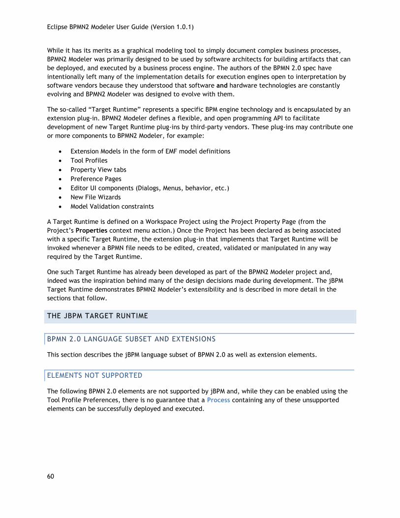
PROJECT-SPECIFIC PREFERENCES
An Eclipse Workspace project may have one or more Natures which may cause some background
processing to happen whenever a project file is changed. For example, the Java nature causes Java
classes to be recompiled whenever a class is edited. A complete discussion of Eclipse Natures is beyond
the scope of this document, but suffice it to say that the BPMN2 Modeler defines a BPMN2 Nature
which invokes a model validation process whenever a BPMN2 file is saved.
Whenever a BPMN2 file is saved, the editor checks if the BPMN2 Nature has been set on the containing
project. If not, it prompts for permission to add the Nature to the project. The Project Preferences
Dialog allows you to enable or disable this prompt dialog, and to define the Target Runtime against
which to validate the files in that project.
Figure 73: Project-Specific Settings
TARGET RUNTIME EXTENSIONS
Eclipse BPMN2 Modeler User Guide (Version 1.0.1)
60
While it has its merits as a graphical modeling tool to simply document complex business processes,
BPMN2 Modeler was primarily designed to be used by software architects for building artifacts that can
be deployed, and executed by a business process engine. The authors of the BPMN 2.0 spec have
intentionally left many of the implementation details for execution engines open to interpretation by
software vendors because they understood that software and hardware technologies are constantly
evolving and BPMN2 Modeler was designed to evolve with them.
The so-called “Target Runtime” represents a specific BPM engine technology and is encapsulated by an
extension plug-in. BPMN2 Modeler defines a flexible, and open programming API to facilitate
development of new Target Runtime plug-ins by third-party vendors. These plug-ins may contribute one
or more components to BPMN2 Modeler, for example:
Extension Models in the form of EMF model definitions
Tool Profiles
Property View tabs
Preference Pages
Editor UI components (Dialogs, Menus, behavior, etc.)
New File Wizards
Model Validation constraints
A Target Runtime is defined on a Workspace Project using the Project Property Page (from the
Project’s Properties context menu action.) Once the Project has been declared as being associated
with a specific Target Runtime, the extension plug-in that implements that Target Runtime will be
invoked whenever a BPMN file needs to be edited, created, validated or manipulated in any way
required by the Target Runtime.
One such Target Runtime has already been developed as part of the BPMN2 Modeler project and,
indeed was the inspiration behind many of the design decisions made during development. The jBPM
Target Runtime demonstrates BPMN2 Modeler’s extensibility and is described in more detail in the
sections that follow.
THE JBPM TARGET RUNTIME
BPMN 2.0 LANGUAGE SUBSET AND EXTENSIONS
This section describes the jBPM language subset of BPMN 2.0 as well as extension elements.
ELEMENTS NOT SUPPORTED
The following BPMN 2.0 elements are not supported by jBPM and, while they can be enabled using the
Tool Profile Preferences, there is no guarantee that a Process containing any of these unsupported
elements can be successfully deployed and executed.
Eclipse BPMN2 Modeler User Guide (Version 1.0.1)
61
Table 2: BPMN 2.0 Elements not supported by jBPM
Call Choreography Call Conversation Choreography Choreography Task
Collaboration Complex Gateway Conversation Conversation Link
Correlation Property Correlation Subscription Data Store Global Tasks
Import Message Flow Participant Standard Loop
Sub Choreography Sub Conversation Transaction Characteristics
BPMN 2.0 ELEMENT EXTENSIONS
This section lists all of the jBPM extension elements and attributes. See the jBPM User Guide for more
information about these extensions [7].
Process – This element has the following extension attributes and elements:
o Version – Version number of the file
o Package Name – The name of the Guvnor package that owns this Process.
o Ad Hoc – A Boolean attribute that identifies this as an Ad Hoc Process. See the
discussion of Ad Hoc Sub-Process in the Appendix.
o Import – This extension element is used instead of the BPMN 2.0 Import element.
Name – the name of a Java class
o Global – This extension element is used to define Process global variables. Global
variables differ from normal Process variables in that they can be accessed outside the
scope of the Process.
Identifier – name of the global variable
Type – Java Type name of the variable
Call Activity– This element has the following extension attributes:
o Wait For Completion - If this property is true, the Call Activity will only continue after
the child Process (the Called Activity) has finished executing. If false, the parent
process flow will continue immediately after starting the child process.
o Independent - If this property is true, the child process is started as an independent
process, which means that it will not be terminated if the parent process finishes or, if
the Sub-Process containing the Call Activity is cancelled for some reason. If false, the
active child process will be cancelled on termination of the parent process (or on
cancellation of the Sub-Process).
Activities – all Activities have extension elements for scripts that can be evaluated before and
after execution.
o On Entry Script – evaluated just before the Activity is executed.
Script Format – either Java or MVEL. The default is Java
Script – the script text
o On Exit Script – evaluated after Activity execution.
Script Format – either Java or MVEL. The default is Java
Script – the script text
Business Rule Task– This element has the following extension attribute:
o Ruleflow Group – In jBPM a Business Rule Task defines a set of rules that need to be
evaluated. This attribute is the name of a specific Ruleflow group, which determines
the evaluation semantics of these rules.
Sequence Flow– This element has the following extension attribute:
Eclipse BPMN2 Modeler User Guide (Version 1.0.1)
62
o Priority – The decision which outgoing flow from an Exclusive Gateway to take, is
made by evaluating the constraints that are linked to each of the outgoing connections.
The constraint with the lowest priority number that evaluates to true is selected.
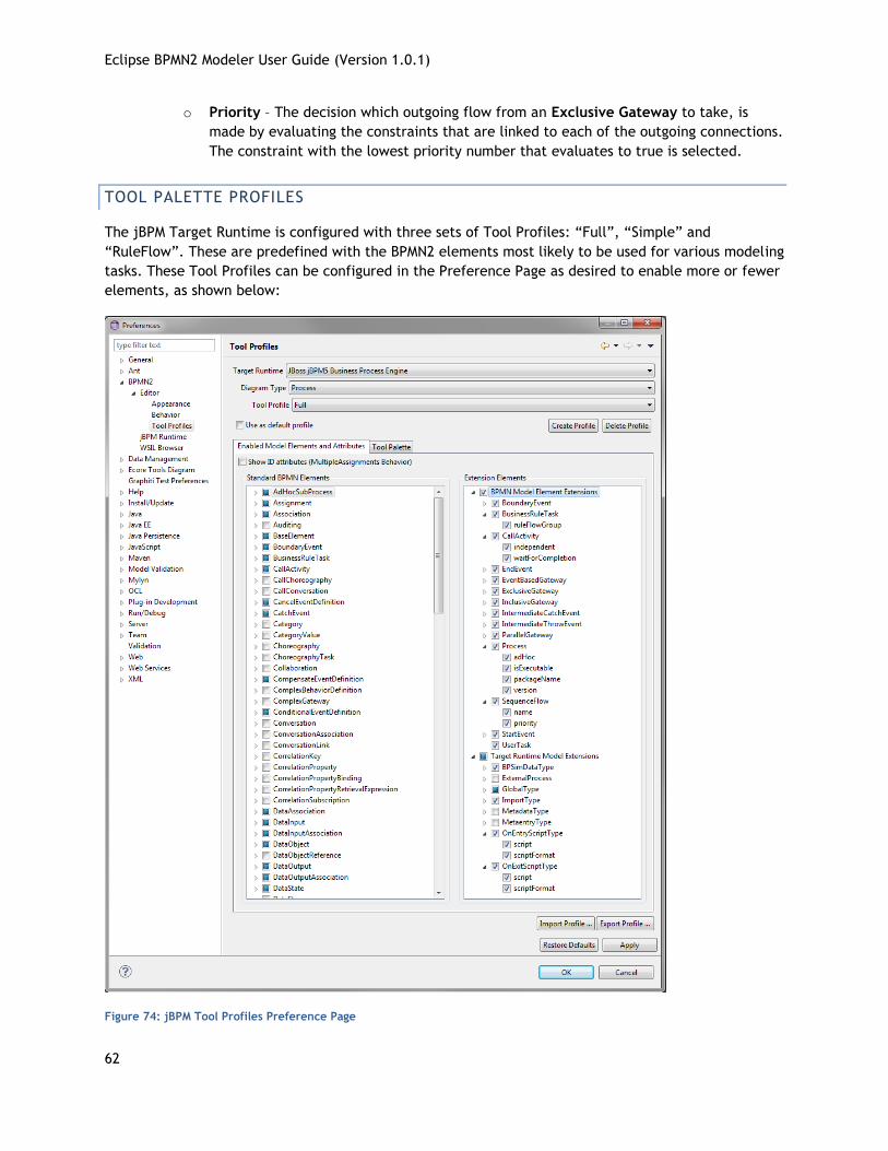
TOOL PALETTE PROFILES
The jBPM Target Runtime is configured with three sets of Tool Profiles: “Full”, “Simple” and
“RuleFlow”. These are predefined with the BPMN2 elements most likely to be used for various modeling
tasks. These Tool Profiles can be configured in the Preference Page as desired to enable more or fewer
elements, as shown below:
Figure 74: jBPM Tool Profiles Preference Page
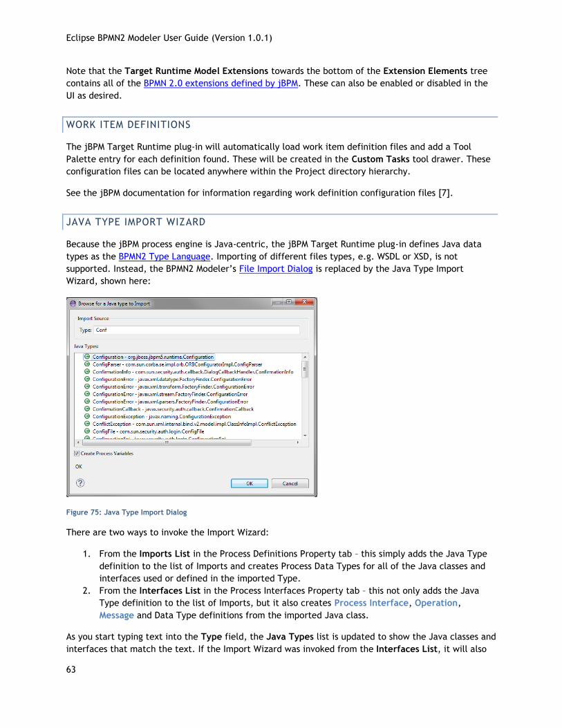
Eclipse BPMN2 Modeler User Guide (Version 1.0.1)
63
Note that the Target Runtime Model Extensions towards the bottom of the Extension Elements tree
contains all of the BPMN 2.0 extensions defined by jBPM. These can also be enabled or disabled in the
UI as desired.
WORK ITEM DEFINITIONS
The jBPM Target Runtime plug-in will automatically load work item definition files and add a Tool
Palette entry for each definition found. These will be created in the Custom Tasks tool drawer. These
configuration files can be located anywhere within the Project directory hierarchy.
See the jBPM documentation for information regarding work definition configuration files [7].
JAVA TYPE IMPORT WIZARD
Because the jBPM process engine is Java-centric, the jBPM Target Runtime plug-in defines Java data
types as the BPMN2 Type Language. Importing of different files types, e.g. WSDL or XSD, is not
supported. Instead, the BPMN2 Modeler’s File Import Dialog is replaced by the Java Type Import
Wizard, shown here:
Figure 75: Java Type Import Dialog
There are two ways to invoke the Import Wizard:
1. From the Imports List in the Process Definitions Property tab – this simply adds the Java Type
definition to the list of Imports and creates Process Data Types for all of the Java classes and
interfaces used or defined in the imported Type.
2. From the Interfaces List in the Process Interfaces Property tab – this not only adds the Java
Type definition to the list of Imports, but it also creates Process Interface, Operation,
Message and Data Type definitions from the imported Java class.
As you start typing text into the Type field, the Java Types list is updated to show the Java classes and
interfaces that match the text. If the Import Wizard was invoked from the Interfaces List, it will also
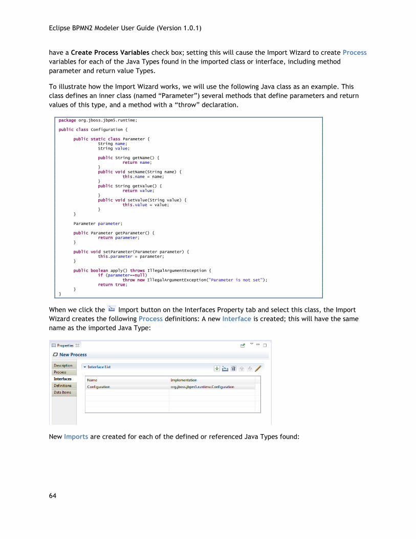
Eclipse BPMN2 Modeler User Guide (Version 1.0.1)
64
have a Create Process Variables check box; setting this will cause the Import Wizard to create Process
variables for each of the Java Types found in the imported class or interface, including method
parameter and return value Types.
To illustrate how the Import Wizard works, we will use the following Java class as an example. This
class defines an inner class (named “Parameter”) several methods that define parameters and return
values of this type, and a method with a “throw” declaration.
package org.jboss.jbpm5.runtime; public class Configuration { public static class Parameter { String name; String value; public String getName() { return name; } public void setName(String name) { this.name = name; } public String getValue() { return value; } public void setValue(String value) { this.value = value; } } Parameter parameter; public Parameter getParameter() { return parameter; } public void setParameter(Parameter parameter) { this.parameter = parameter; } public boolean apply() throws IllegalArgumentException { if (parameter==null) throw new IllegalArgumentException("Parameter is not set"); return true; } }
When we click the Import button on the Interfaces Property tab and select this class, the Import
Wizard creates the following Process definitions: A new Interface is created; this will have the same
name as the imported Java Type:
New Imports are created for each of the defined or referenced Java Types found:
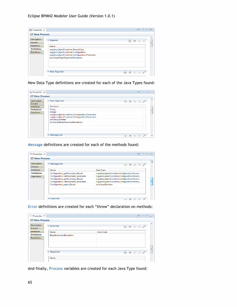
Eclipse BPMN2 Modeler User Guide (Version 1.0.1)
65
New Data Type definitions are created for each of the Java Types found:
Message definitions are created for each of the methods found:
Error definitions are created for each “throw” declaration on methods:
And finally, Process variables are created for each Java Type found:
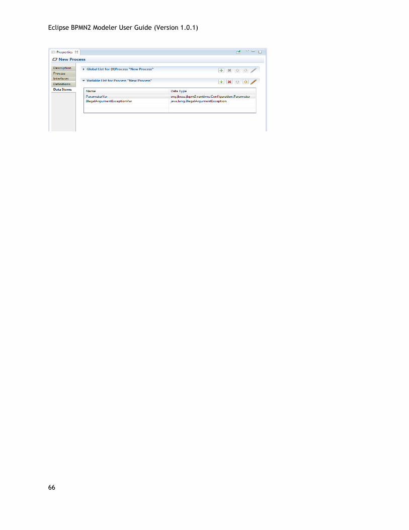
Eclipse BPMN2 Modeler User Guide (Version 1.0.1)
66
Eclipse BPMN2 Modeler User Guide (Version 1.0.1)
67
APPENDIX: BPMN 2.0 REFERENCE This appendix contains a brief description of all of the BPMN 2.0 elements and their visual
representation in BPMN2 Modeler. There is also a detailed discussion of the supported diagram types.
CONNECTIONS
ASSOCIATION
An Association is used to link information and Artifacts with BPMN graphical elements. Text
Annotations and other Artifacts can be associated with the graphical elements. An arrowhead on the
Association indicates a direction of flow, when appropriate.
CONVERSATION LINK
Conversation Links are used to connect Conversations to and from Participants (Pools)
DATA ASSOCIATION
Data Associations show a flow of data out of, or in to an Activity. An arrow head is used to indicate
the direction of the data flow.
Data Associations are used to move data between Data Objects, Process Variables, and inputs and
outputs of Activities, Processes, and Global Tasks. Process execution does not flow along a Data
Association, and as a result they have no direct effect on the flow of the Process. The purpose of
retrieving data from Data Objects or Process Data Inputs is to fill the Activities inputs and later push
the output values from the execution of the Activity back into Data Objects or Process Data Outputs.
MESSAGE FLOW
A Message Flow is used to show the flow of Messages between two Participants. Pools in a
Collaboration Diagram are used to represent the two Participants.
SEQUENCE FLOW
A Sequence Flow is used to show the order in which Activities will be performed in a Process or
Choreography. A Sequence Flow can optionally define a condition Expression, indicating that control will
be passed down the Sequence Flow only if the Expression evaluates to true. This Expression is typically
used when the source of the Sequence Flow is a Gateway or an Activity. A Sequence Flow that has an
Exclusive, Inclusive, or Complex Gateway or an Activity as its source can also be defined as "default".
Such a Sequence Flow will have a marker to show that it is a default flow. The default Sequence Flow is
taken only if all the other outgoing Sequence Flows from the Activity or Gateway are not valid (i.e., their
condition Expressions are false).
EVENTS
Eclipse BPMN2 Modeler User Guide (Version 1.0.1)
68
BOUNDARY EVENT
Boundary Events are attached to the borders of an Activity and are used to handle conditions
(Event Definitions) that may have resulted during execution of the Activity.
END EVENT
As the name implies, the End Event indicates where a Process will end. In terms of Sequence
Flows, the End Event ends the flow of the Process, and thus, will not have any outgoing
Sequence Flows and no Sequence Flow can connect from an End Event. An End Event may have one or
more triggers (Event Definitions), which are passed back to an invoking or containing Process (if any).
INTERMEDIATE CATCH EVENT
The Intermediate Catch Event is used to handle some kind of condition (Event Definition) that
has occurred within the process or in an external process.
INTERMEDIATE THROW EVENT
The Intermediate Throw Event is used to report some kind of condition (Event Definition) to
an invoking or containing Process. The receiving Process should be designed so that it is
prepared to handle the event, either with a Start Event, Intermediate Catch Event or a Boundary
Event.
START EVENT
As the name implies, the Start Event indicates where a particular Process will start. In terms of
Sequence Flows, the Start Event starts the flow of the Process, and thus, will not have any
incoming Sequence Flows and no Sequence Flow can connect to a Start Event. A Start
Event may have one or more event triggers (Event Definitions) which cause the Process to be initiated.
EVENT DEFINITIONS
Event Definitions determine the behavior of Events. An Event may have zero or more Event
Definitions.
CANCEL
This type of Event Definition is only allowed when used within a Transaction Sub-Process. It is used to
“roll back” the effects of the Transaction.
COMPENSATE
Eclipse BPMN2 Modeler User Guide (Version 1.0.1)
69
Compensation is similar to a Cancel Event in that it is used to reverse the effects of one or more
Activities. In this case, the Activities may not be contained in a Transaction Sub-Process, so each
Activity needs to be compensated separately.
CONDITIONAL
This type of Event is triggered when a condition becomes true. The Event Definition contains the
condition Expression.
ERROR
An Error Event Definition is used to throw or catch an Error. The Error payload is associated with a
variable owned by the Event. See Error below, for more details.
ESCALATION
An Escalation Event Definition is used to throw or catch an Escalation. The Escalation payload is
associated with a variable owned by the Event. See Escalation below, for more details.
LINK
A Link is a mechanism for connecting two sections of a Process. Link Events can be used to create
looping situations or to avoid long Sequence Flow lines. Link Event uses are limited to a single Process
level (i.e., they cannot link a parent Process with a Sub-Process). Paired Intermediate Events can
also be used as “Off-Page Connectors” for printing a Process across multiple pages. They can also be
used as generic “Go To” objects within the Process level.
MESSAGE
A Message Event Definition can be used to either send or receive a Message. The Message payload is
associated with a variable owned by the Event. See Message below, for more details.
SIGNAL
A Signal Event Definition is used to throw or catch a Signal. See Signal below, for more details.
TERMINATE
This type of End Event indicates that all Activities in the Process should be immediately ended. This
includes all instances of multi-instances. The Process is ended without compensation or event
handling.
TIMER
The Timer Event Definition acts as a delay mechanism based on a specific time-date or a specific cycle
(e.g., every Monday at 9am) can be set that will trigger the Event.
Eclipse BPMN2 Modeler User Guide (Version 1.0.1)
70
GATEWAYS
A Gateway must have multiple incoming or multiple outgoing Sequence Flows (i.e., it must either
merge or split the process flow). The Gateway Direction property determines its behavior; this property
can be one of the following
Unspecified – the Gateway may have both multiple incoming and outgoing Sequence Flows
Mixed – the Gateway must have both multiple incoming and outgoing Sequence Flows
Converging – the Gateway must have multiple incoming Sequence Flows, but may have only
one outgoing Sequence Flow
Diverging– the Gateway may have only one incoming Sequence Flow, but must have multiple
outgoing Sequence Flows
COMPLEX GATEWAY
The Complex Gateway can be used to model complex synchronization behavior. An
Expression is used to describe the precise behavior. For example, this Expression could
specify that three out of five incoming Sequence Flows are needed to activate the Gateway.
The outgoing paths that are taken by the Gateway, is determined by conditions on the outgoing
Sequence Flows as in the split behavior of the Inclusive Gateway.
EXCLUSIVE GATEWAY
A diverging Exclusive Gateway (decision) is used to create alternative paths within a Process
flow. This is basically the "diversion point in the road" for a Process. For a given instance of
the Process, only one of the paths can be taken. A decision can be thought of as a question
that is asked at a particular point in the Process. The question has a defined set of alternative answers.
Each answer is associated with a condition Expression that is associated with a Gateway's outgoing
Sequence Flows.
A default path can optionally be identified, to be taken in the event that none of the conditional
Expressions evaluate to true. If a default path is not specified and the Process is executed such that
none of the conditional Expressions evaluates to true, a runtime exception occurs.
A converging Exclusive Gateway is used to merge alternative paths.
EVENT BASED GATEWAY
The Event-Based Gateway represents a branching point in the Process where the alternative
paths that follow the Gateway are based on events that occur, rather than the evaluation of
expressions using Process data (as with an Exclusive or Inclusive Gateway). A specific event,
usually the receipt of a Message, determines the path that will be taken. Basically, the decision is
made by another Participant based on data that is not visible to a Process, thus requiring the use of
the Event-Based Gateway.
INCLUSIVE GATEWAY
Eclipse BPMN2 Modeler User Guide (Version 1.0.1)
71
A diverging Inclusive Gateway (inclusive decision) can be used to create alternative but also
parallel paths within a Process flow. Unlike the Exclusive Gateway, all condition expressions
are evaluated. The true evaluation of one condition expression does not exclude the
evaluation of other condition expressions. All Sequence Flows with a true evaluation will be traversed.
Since each path is considered to be independent, all combinations of the paths may be taken, from
zero to all. However, it should be designed so that at least one path is taken.
A default path can optionally be identified, to be taken in the event that none of the conditional
Expressions evaluate to true. If a default path is not specified and the Process is executed such that
none of the conditional Expressions evaluates to true, a runtime exception occurs.
A converging Inclusive Gateway is used to merge a combination of alternative and parallel paths.
PARALLEL GATEWAY
A Parallel Gateway is used to synchronize (combine) parallel flows and to create parallel
flows. A Parallel Gateway creates parallel paths without checking any conditions; each
outgoing Sequence Flow is passed control upon execution of this Gateway. For incoming
flows, the Parallel Gateway will wait for all incoming flows before triggering the flow through its
outgoing Sequence Flows.
ACTIVITIES
BUSINESS RULE TASK
A Business Rule Task provides a mechanism for the Process to provide input to a
Business Rules Engine and to get the output of calculations that the Business Rules
Engine might provide.
CHOREOGRAPHY TASK
A Choreography Task is an atomic Activity in a Choreography Process. It represents an
Interaction, which may be one or two Message exchanges between two Participants.
MANUAL TASK
A Manual Task is a task that is not managed by any business process engine. It can be
considered as an unmanaged task, in the sense that the business process engine does
not track the start and completion of such a task. An example of this could be a paper
based instruction for a telephone technician to install a telephone at a customer location.
RECEIVE TASK
Eclipse BPMN2 Modeler User Guide (Version 1.0.1)
72
A Receive Task is a simple task that is designed to wait for a Message to arrive from
an external Participant (relative to the Process). Once the Message has been received,
the task is completed.
SCRIPT TASK
A Script Task is executed by a business process engine The modeler or implementer
defines a script in a language that the engine can interpret When the task is ready to
start, the engine will execute the script When the script is completed, the task will
also be completed.
SEND TASK
A Send Task is a simple task that is designed to send a Message to an external
Participant (relative to the Process). Once the Message has been sent, the task is
completed.
SERVICE TASK
A Service Task is a task that uses some sort of service, which could be a Web service
or an automated application.
A Service Task defines an Implementation which is the underlying technology that will be used to
implement the service. Valid values are "##unspecified" for leaving the implementation technology
open, "##WebService" for the Web service technology or a URI identifying any other technology or
coordination protocol.
TASK
A Task is an atomic Activity that is included within a Process. A Task is used when the
work in the Process is not broken down to a finer level of Process detail.
USER TASK
A User Task is a typical workflow task where a human actor performs the task with the
assistance of a software application. The lifecycle of the task is managed by a software
component (called the “Task Manager”) and is typically executed in the context of a
Process. The User Task can be implemented using different technologies, specified by the
Implementation attribute. Besides the Web service technology, any technology can be used. A User
Task for instance can be implemented using WSHumanTask by setting Implementation to
“http://docs.oasis-open.org/ns/bpel4people/ws-humantask/protocol/200803”.
DATA ELEMENTS
Eclipse BPMN2 Modeler User Guide (Version 1.0.1)
73
This section describes all of the possible data elements that can be manipulated by Activities in a
Process, both visual and non-visual.
The BPMN 2.0 spec also provides for a “Data State”, which is a state of the data contained in a data
element. The definition of these states, e.g., possible values, and any specific semantics are out of
scope of the BPMN 2.0 spec. Therefore, BPMN adopters can use this element and the BPMN extensibility
capabilities to define their own states.
DATA INPUT/OUTPUT
Activities and Processes often required data in order to execute. In addition they
may produce data during or as a result of execution. Data requirements are
captured as Data Inputs and Data Outputs.
INPUT AND OUTPUT SETS
An Activity or Process may be designed such that it can execute with differing sets of input data. This
allows the process architect greater flexibility in designing the process, since not all data may be
available or even required when executing an Activity. For example, some information (e.g. a city
name) can be derived or looked up (by, e.g. city postal code) if not provided to the Activity at
runtime. This is similar to the concept of method overloading in Java or C++.
BPMN 2.0 introduced the concept of Input Sets and Output Sets to support this concept. Essentially,
Data Inputs, when grouped together (the “Input Set”), define a valid set of data inputs for an Activity.
Data Outputs grouped together (the “Output Set”) define the set of data items produced when the
Activity completes. These Input and Output Sets also allow you to specify which data items are
optionally available on input or optionally created on output, and which items are required or
mandatory.
Input and Output Sets can also define mutual dependencies; an Input Set can indicate which Output
Sets are produced, and an Output Set can indicate the Input Sets needed to produce the output data.
DATA OBJECT
Data Objects are the primary construct for modeling data within the Process flow. A Data
Object has a well-defined lifecycle and structure. A Data Object can appear multiple times
in a Process diagram, each of which references the same Data Object instance. These
references are used to simplify diagram connections.
DATA STORE
A Data Store provides a mechanism for Activities to retrieve or update stored information
that will persist beyond the scope of the Process. The same Data Store can be visualized,
through a Data Store Reference, in one or more places in the Process.
Eclipse BPMN2 Modeler User Guide (Version 1.0.1)
74
MESSAGE
A Message represents the content of a communication between two Participants.
ERROR
An Error represents the content of an Error Event or the Fault of a failed Operation.
ESCALATION
An Escalation identifies a business situation that a Process might need to react to.
SIGNAL
Signals are triggers generated in the Pool they are published. They are typically used for
broadcast communication within and across Processes, across Pools, and between Process
diagrams.
RESOURCE
A Resource is an actor or responsible party that participates in an activity. This could be, for example,
a specific individual, a group, an organization role or position, or an organization. Resources are
assigned to Activities during Process execution time.
A Resource may need additional information to complete a task. This could be, for example, a
customer’s contact information, an order request, invoice, etc. This information is represented as
Resource Parameters. In an executable Process, Resource Parameters must be in the form of data
items that are accessible within the scope of the Activity that owns the Resource.
VARIABLE (PROPERTY)
Properties, like Data Objects, are data containers. But, unlike Data Objects, they are not visually
displayed on a diagram. Only Processes, Activities, and Events may contain Properties. Properties
are analogous to “Variables” in the context of a programming language, in that they are used to store,
transform and convey data as it is moved through the process. Properties have the same properties as
Data Objects, in that they have a well-defined structure, kind and cardinality.
BPMN2 Modeler uses the term “Variable” instead of “Property” because it seems more intuitive to the
software developer, though they refer to the same BPMN2 model element. Also, because the term
“Property” is so ubiquitous it can sometimes cause confusion when discussing the “properties of a
Property”.
DATA TYPE (ITEMDEFINITION)
BPMN elements, such as Data Objects and Messages, represent items that are manipulated during
process flows. The set of characteristics that describe these items are known in BPMN 2.0 as Item
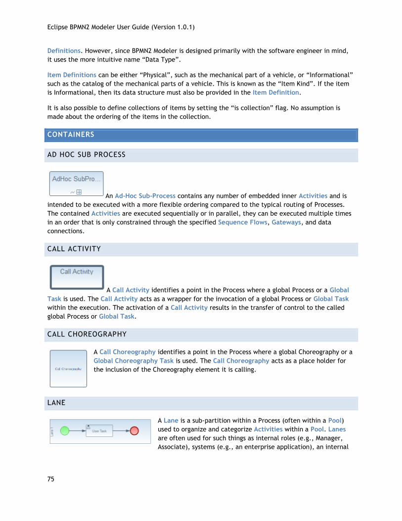
Eclipse BPMN2 Modeler User Guide (Version 1.0.1)
75
Definitions. However, since BPMN2 Modeler is designed primarily with the software engineer in mind,
it uses the more intuitive name “Data Type”.
Item Definitions can be either “Physical”, such as the mechanical part of a vehicle, or “Informational”
such as the catalog of the mechanical parts of a vehicle. This is known as the “Item Kind”. If the item
is Informational, then its data structure must also be provided in the Item Definition.
It is also possible to define collections of items by setting the “is collection” flag. No assumption is
made about the ordering of the items in the collection.
CONTAINERS
AD HOC SUB PROCESS
An Ad-Hoc Sub-Process contains any number of embedded inner Activities and is
intended to be executed with a more flexible ordering compared to the typical routing of Processes.
The contained Activities are executed sequentially or in parallel, they can be executed multiple times
in an order that is only constrained through the specified Sequence Flows, Gateways, and data
connections.
CALL ACTIVITY
A Call Activity identifies a point in the Process where a global Process or a Global
Task is used. The Call Activity acts as a wrapper for the invocation of a global Process or Global Task
within the execution. The activation of a Call Activity results in the transfer of control to the called
global Process or Global Task.
CALL CHOREOGRAPHY
A Call Choreography identifies a point in the Process where a global Choreography or a
Global Choreography Task is used. The Call Choreography acts as a place holder for
the inclusion of the Choreography element it is calling.
LANE
A Lane is a sub-partition within a Process (often within a Pool)
used to organize and categorize Activities within a Pool. Lanes
are often used for such things as internal roles (e.g., Manager,
Associate), systems (e.g., an enterprise application), an internal
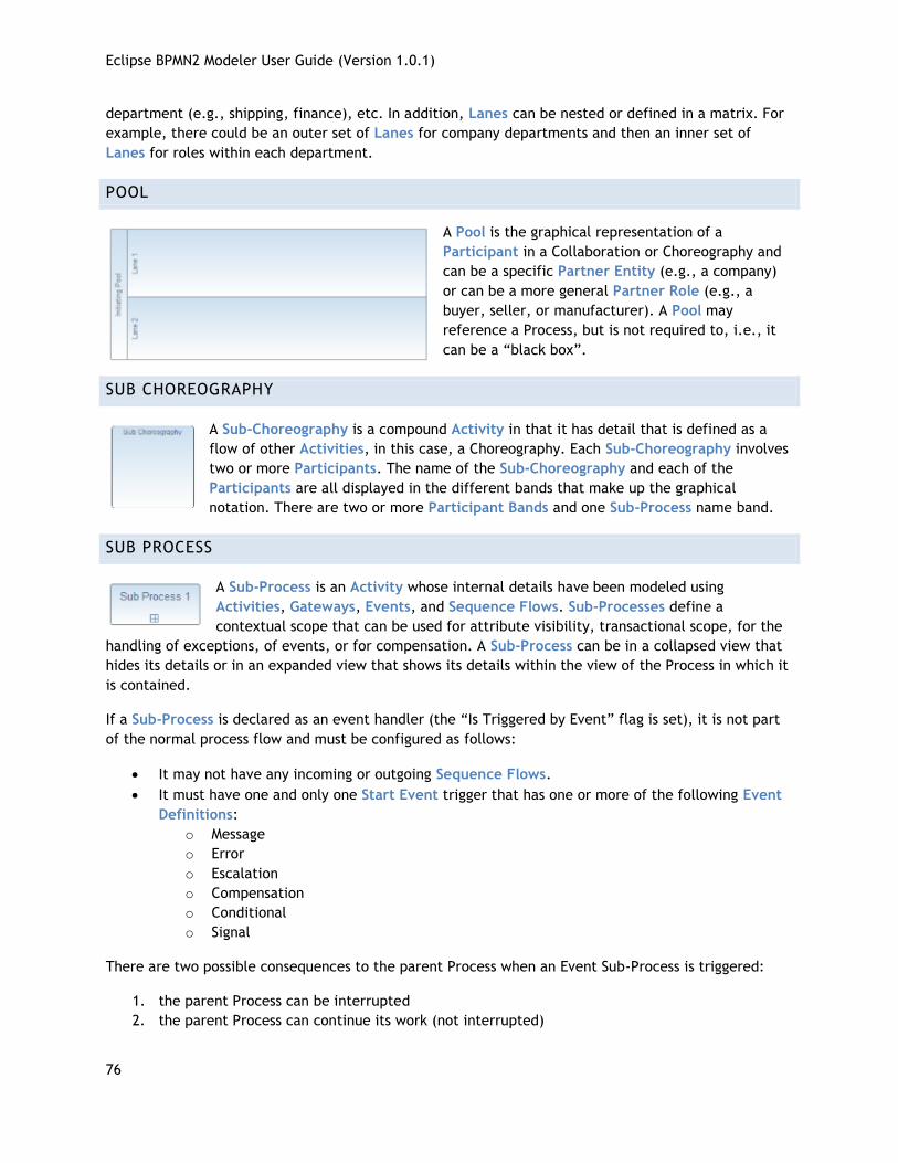
Eclipse BPMN2 Modeler User Guide (Version 1.0.1)
76
department (e.g., shipping, finance), etc. In addition, Lanes can be nested or defined in a matrix. For
example, there could be an outer set of Lanes for company departments and then an inner set of
Lanes for roles within each department.
POOL
A Pool is the graphical representation of a
Participant in a Collaboration or Choreography and
can be a specific Partner Entity (e.g., a company)
or can be a more general Partner Role (e.g., a
buyer, seller, or manufacturer). A Pool may
reference a Process, but is not required to, i.e., it
can be a “black box”.
SUB CHOREOGRAPHY
A Sub-Choreography is a compound Activity in that it has detail that is defined as a
flow of other Activities, in this case, a Choreography. Each Sub-Choreography involves
two or more Participants. The name of the Sub-Choreography and each of the
Participants are all displayed in the different bands that make up the graphical
notation. There are two or more Participant Bands and one Sub-Process name band.
SUB PROCESS
A Sub-Process is an Activity whose internal details have been modeled using
Activities, Gateways, Events, and Sequence Flows. Sub-Processes define a
contextual scope that can be used for attribute visibility, transactional scope, for the
handling of exceptions, of events, or for compensation. A Sub-Process can be in a collapsed view that
hides its details or in an expanded view that shows its details within the view of the Process in which it
is contained.
If a Sub-Process is declared as an event handler (the “Is Triggered by Event” flag is set), it is not part
of the normal process flow and must be configured as follows:
It may not have any incoming or outgoing Sequence Flows.
It must have one and only one Start Event trigger that has one or more of the following Event
Definitions:
o Message
o Error
o Escalation
o Compensation
o Conditional
o Signal
There are two possible consequences to the parent Process when an Event Sub-Process is triggered:
1. the parent Process can be interrupted
2. the parent Process can continue its work (not interrupted)
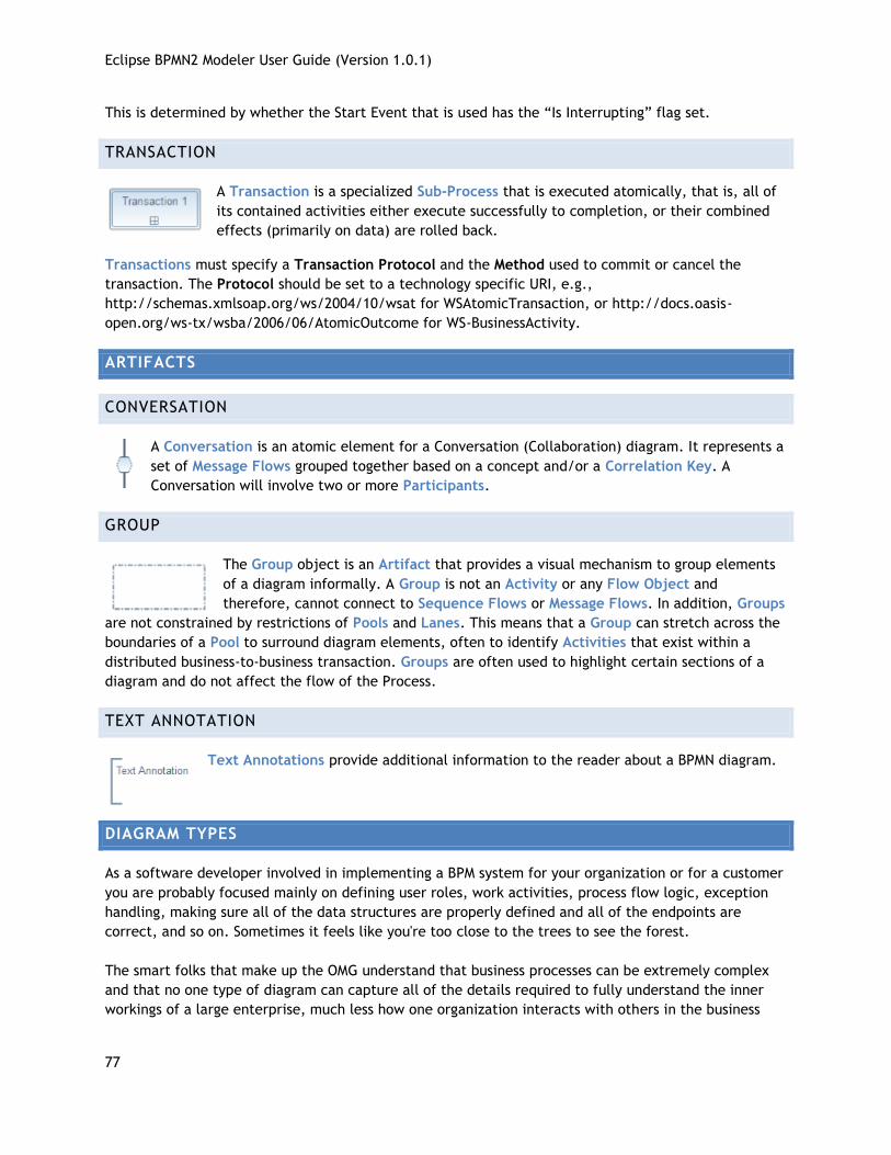
Eclipse BPMN2 Modeler User Guide (Version 1.0.1)
77
This is determined by whether the Start Event that is used has the “Is Interrupting” flag set.
TRANSACTION
A Transaction is a specialized Sub-Process that is executed atomically, that is, all of
its contained activities either execute successfully to completion, or their combined
effects (primarily on data) are rolled back.
Transactions must specify a Transaction Protocol and the Method used to commit or cancel the
transaction. The Protocol should be set to a technology specific URI, e.g.,
http://schemas.xmlsoap.org/ws/2004/10/wsat for WSAtomicTransaction, or http://docs.oasis-
open.org/ws-tx/wsba/2006/06/AtomicOutcome for WS-BusinessActivity.
ARTIFACTS
CONVERSATION
A Conversation is an atomic element for a Conversation (Collaboration) diagram. It represents a
set of Message Flows grouped together based on a concept and/or a Correlation Key. A
Conversation will involve two or more Participants.
GROUP
The Group object is an Artifact that provides a visual mechanism to group elements
of a diagram informally. A Group is not an Activity or any Flow Object and
therefore, cannot connect to Sequence Flows or Message Flows. In addition, Groups
are not constrained by restrictions of Pools and Lanes. This means that a Group can stretch across the
boundaries of a Pool to surround diagram elements, often to identify Activities that exist within a
distributed business-to-business transaction. Groups are often used to highlight certain sections of a
diagram and do not affect the flow of the Process.
TEXT ANNOTATION
Text Annotations provide additional information to the reader about a BPMN diagram.
DIAGRAM TYPES
As a software developer involved in implementing a BPM system for your organization or for a customer
you are probably focused mainly on defining user roles, work activities, process flow logic, exception
handling, making sure all of the data structures are properly defined and all of the endpoints are
correct, and so on. Sometimes it feels like you're too close to the trees to see the forest.
The smart folks that make up the OMG understand that business processes can be extremely complex
and that no one type of diagram can capture all of the details required to fully understand the inner
workings of a large enterprise, much less how one organization interacts with others in the business
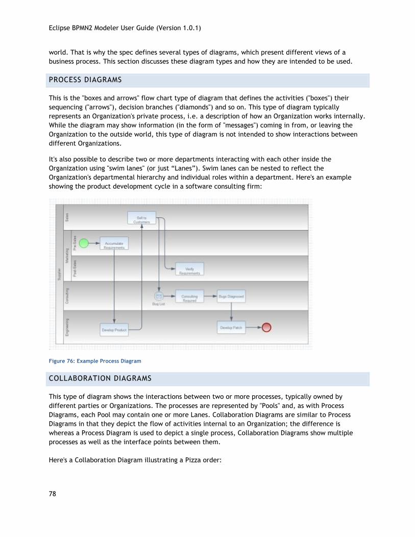
Eclipse BPMN2 Modeler User Guide (Version 1.0.1)
78
world. That is why the spec defines several types of diagrams, which present different views of a
business process. This section discusses these diagram types and how they are intended to be used.
PROCESS DIAGRAMS
This is the "boxes and arrows" flow chart type of diagram that defines the activities ("boxes") their
sequencing ("arrows"), decision branches ("diamonds") and so on. This type of diagram typically
represents an Organization's private process, i.e. a description of how an Organization works internally.
While the diagram may show information (in the form of "messages") coming in from, or leaving the
Organization to the outside world, this type of diagram is not intended to show interactions between
different Organizations.
It's also possible to describe two or more departments interacting with each other inside the
Organization using "swim lanes" (or just “Lanes”). Swim lanes can be nested to reflect the
Organization's departmental hierarchy and individual roles within a department. Here's an example
showing the product development cycle in a software consulting firm:
Figure 76: Example Process Diagram
COLLABORATION DIAGRAMS
This type of diagram shows the interactions between two or more processes, typically owned by
different parties or Organizations. The processes are represented by "Pools" and, as with Process
Diagrams, each Pool may contain one or more Lanes. Collaboration Diagrams are similar to Process
Diagrams in that they depict the flow of activities internal to an Organization; the difference is
whereas a Process Diagram is used to depict a single process, Collaboration Diagrams show multiple
processes as well as the interface points between them.
Here's a Collaboration Diagram illustrating a Pizza order:
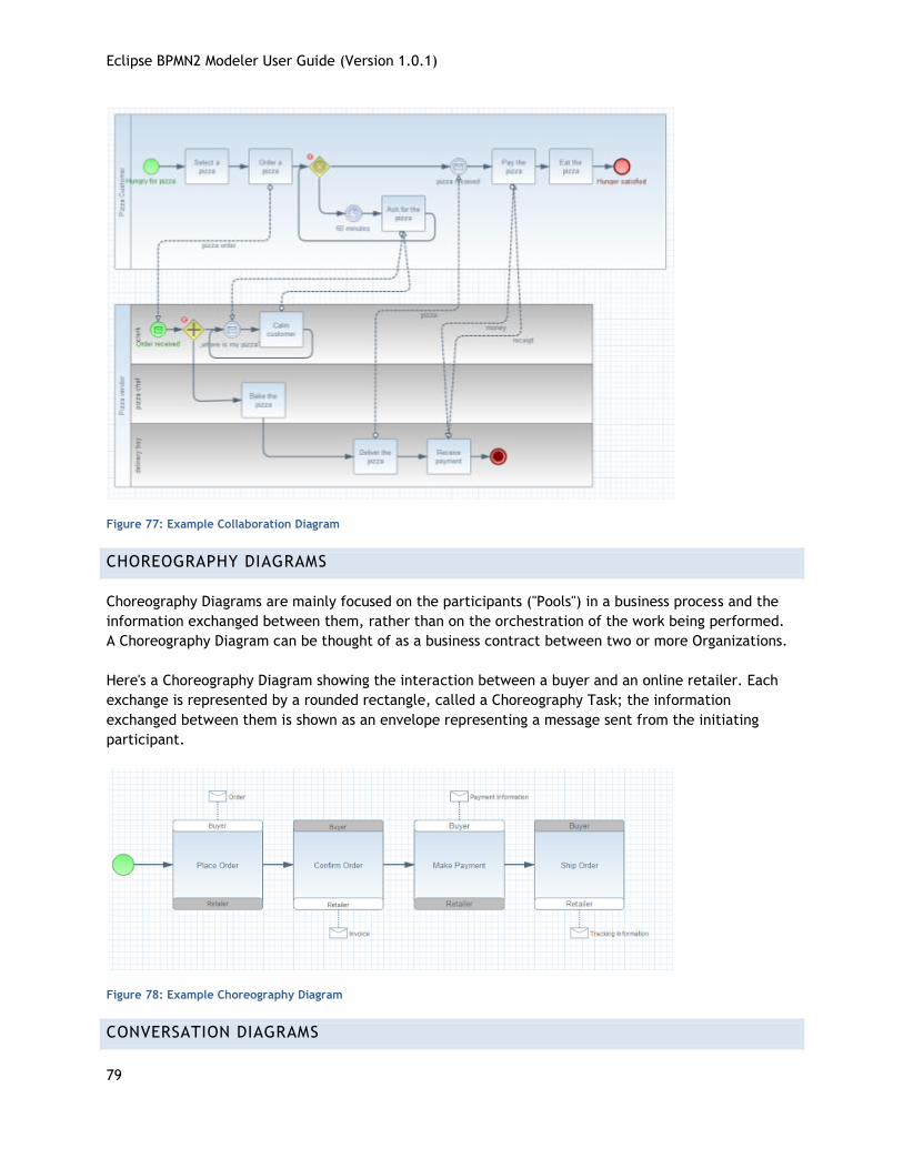
Eclipse BPMN2 Modeler User Guide (Version 1.0.1)
79
Figure 77: Example Collaboration Diagram
CHOREOGRAPHY DIAGRAMS
Choreography Diagrams are mainly focused on the participants ("Pools") in a business process and the
information exchanged between them, rather than on the orchestration of the work being performed.
A Choreography Diagram can be thought of as a business contract between two or more Organizations.
Here's a Choreography Diagram showing the interaction between a buyer and an online retailer. Each
exchange is represented by a rounded rectangle, called a Choreography Task; the information
exchanged between them is shown as an envelope representing a message sent from the initiating
participant.
Figure 78: Example Choreography Diagram
CONVERSATION DIAGRAMS
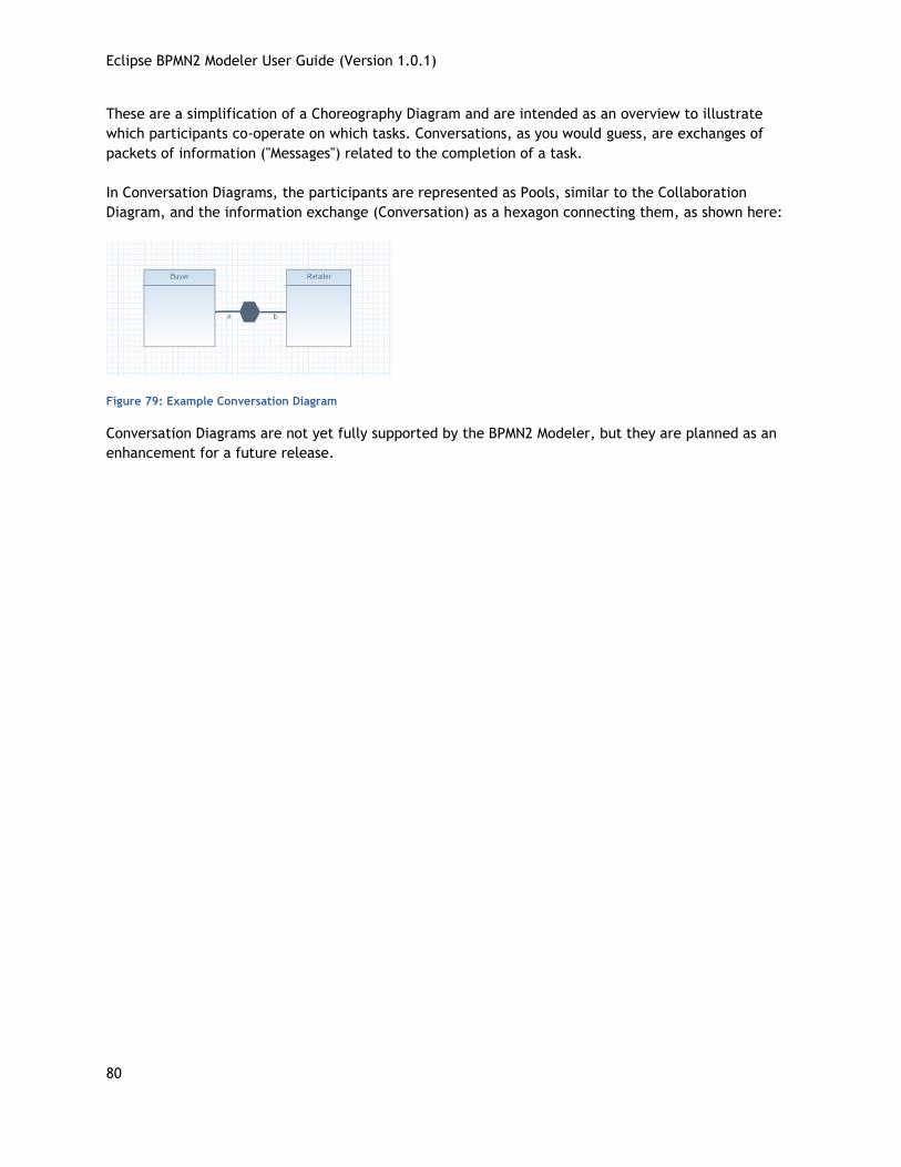
Eclipse BPMN2 Modeler User Guide (Version 1.0.1)
80
These are a simplification of a Choreography Diagram and are intended as an overview to illustrate
which participants co-operate on which tasks. Conversations, as you would guess, are exchanges of
packets of information ("Messages") related to the completion of a task.
In Conversation Diagrams, the participants are represented as Pools, similar to the Collaboration
Diagram, and the information exchange (Conversation) as a hexagon connecting them, as shown here:
Figure 79: Example Conversation Diagram
Conversation Diagrams are not yet fully supported by the BPMN2 Modeler, but they are planned as an
enhancement for a future release.
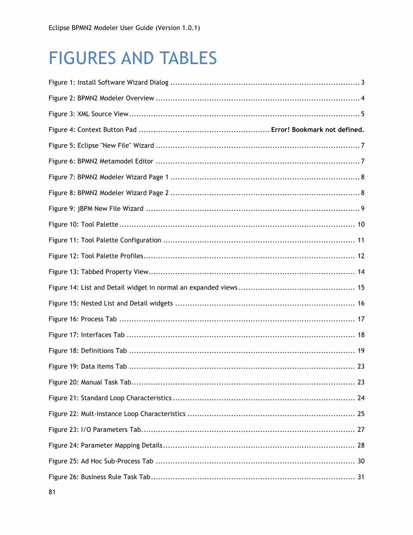
Eclipse BPMN2 Modeler User Guide (Version 1.0.1)
81
FIGURES AND TABLES Figure 1: Install Software Wizard Dialog .............................................................................. 3
Figure 2: BPMN2 Modeler Overview .................................................................................... 4
Figure 3: XML Source View ............................................................................................... 5
Figure 4: Context Button Pad ...................................................... Error! Bookmark not defined.
Figure 5: Eclipse "New File" Wizard .................................................................................... 7
Figure 6: BPMN2 Metamodel Editor .................................................................................... 7
Figure 7: BPMN2 Modeler Wizard Page 1 .............................................................................. 8
Figure 8: BPMN2 Modeler Wizard Page 2 .............................................................................. 8
Figure 9: jBPM New File Wizard ........................................................................................ 9
Figure 10: Tool Palette ................................................................................................. 10
Figure 11: Tool Palette Configuration ............................................................................... 11
Figure 12: Tool Palette Profiles ....................................................................................... 12
Figure 13: Tabbed Property View..................................................................................... 14
Figure 14: List and Detail widget in normal an expanded views ................................................ 15
Figure 15: Nested List and Detail widgets .......................................................................... 16
Figure 16: Process Tab ................................................................................................. 17
Figure 17: Interfaces Tab .............................................................................................. 18
Figure 18: Definitions Tab ............................................................................................. 19
Figure 19: Data Items Tab ............................................................................................. 23
Figure 20: Manual Task Tab............................................................................................ 23
Figure 21: Standard Loop Characteristics ........................................................................... 24
Figure 22: Mult-Instance Loop Characteristics ..................................................................... 25
Figure 23: I/O Parameters Tab ........................................................................................ 27
Figure 24: Parameter Mapping Details ............................................................................... 28
Figure 25: Ad Hoc Sub-Process Tab .................................................................................. 30
Figure 26: Business Rule Task Tab .................................................................................... 31
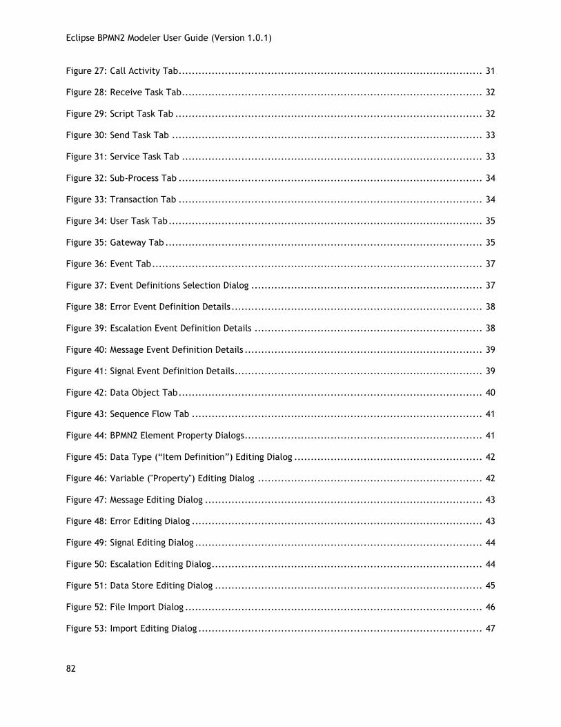
Eclipse BPMN2 Modeler User Guide (Version 1.0.1)
82
Figure 27: Call Activity Tab ............................................................................................ 31
Figure 28: Receive Task Tab ........................................................................................... 32
Figure 29: Script Task Tab ............................................................................................. 32
Figure 30: Send Task Tab .............................................................................................. 33
Figure 31: Service Task Tab ........................................................................................... 33
Figure 32: Sub-Process Tab ............................................................................................ 34
Figure 33: Transaction Tab ............................................................................................ 34
Figure 34: User Task Tab ............................................................................................... 35
Figure 35: Gateway Tab ................................................................................................ 35
Figure 36: Event Tab .................................................................................................... 37
Figure 37: Event Definitions Selection Dialog ...................................................................... 37
Figure 38: Error Event Definition Details ............................................................................ 38
Figure 39: Escalation Event Definition Details ..................................................................... 38
Figure 40: Message Event Definition Details ........................................................................ 39
Figure 41: Signal Event Definition Details ........................................................................... 39
Figure 42: Data Object Tab ............................................................................................ 40
Figure 43: Sequence Flow Tab ........................................................................................ 41
Figure 44: BPMN2 Element Property Dialogs........................................................................ 41
Figure 45: Data Type (“Item Definition”) Editing Dialog ......................................................... 42
Figure 46: Variable ("Property") Editing Dialog .................................................................... 42
Figure 47: Message Editing Dialog .................................................................................... 43
Figure 48: Error Editing Dialog ........................................................................................ 43
Figure 49: Signal Editing Dialog ....................................................................................... 44
Figure 50: Escalation Editing Dialog .................................................................................. 44
Figure 51: Data Store Editing Dialog ................................................................................. 45
Figure 52: File Import Dialog .......................................................................................... 46
Figure 53: Import Editing Dialog ...................................................................................... 47
Eclipse BPMN2 Modeler User Guide (Version 1.0.1)
83
Figure 54: Namespace Editing Dialog ................................................................................ 47
Figure 55: Edit Resource Dialog ....................................................................................... 48
Figure 56: Edit Resource Parameter Dialog ......................................................................... 48
Figure 57: Edit Resource Role Dialog ................................................................................ 48
Figure 58: Export Diagram Dialog..................................................................................... 49
Figure 59: Outline Viewer Title Bar Buttons ........................................................................ 49
Figure 60: Sample Process ............................................................................................. 49
Figure 61: Business Model Figure 62: Diagram Interchange Model Figure 63: Thumbnail ................. 50
Figure 64: BPMN2 General Settings................................................................................... 52
Figure 65: Editor Appearance (Shapes) .............................................................................. 53
Figure 66: Editor Appearance (Connections) ....................................................................... 54
Figure 67: Editor Behavior ............................................................................................. 55
Figure 68: Create Profile Dialog ...................................................................................... 56
Figure 69: Tool Profiles (Model Enablement) ....................................................................... 56
Figure 70: Tool Profiles (Tool Palette) .............................................................................. 57
Figure 71: jBPM Runtime Preferences ............................................................................... 58
Figure 72: WSIL Browser Preferences ................................................................................ 59
Figure 73: Project-Specific Settings .................................................................................. 59
Figure 74: jBPM Tool Profiles Preference Page .................................................................... 62
Figure 75: Java Type Import Dialog .................................................................................. 63
Figure 76: Example Process Diagram ................................................................................ 78
Figure 77: Example Collaboration Diagram ......................................................................... 79
Figure 78: Example Choreography Diagram ......................................................................... 79
Figure 79: Example Conversation Diagram .......................................................................... 80
Table 1: Eclipse Platform Compatibility .............................................................................. 1
Table 2: BPMN 2.0 Elements not supported by jBPM .............................................................. 61
Eclipse BPMN2 Modeler User Guide (Version 1.0.1)
84
REFERENCES
[1] "Business Process Model and Notation (BPMN)," OMG, 1 2011. [Online]. Available:
http://www.omg.org/spec/BPMN/2.0/.
[2] J. Freund and B. Rücker, Real Life BPMN, Berlin: Camunda, 2012.
[3] T. Allweyer, BPMN 2.0 - Introduction to the Standard for Business Process Modeling, Books on
Demand GmbH, Norderstedt, 2010.
[4] "Eclipse BPMN2," [Online]. Available:
http://www.eclipse.org/modeling/mdt/?project=bpmn2#bpmn2.
[5] "Business Process Simulation Interchange Standard," BPSim.org, [Online]. Available:
http://www.bpsim.org/.
[6] P. Brittenham, "An overview of the Web Services Inspection Language," IBM, 1 6 2002. [Online].
Available: http://www.ibm.com/developerworks/webservices/library/ws-wsilover/.
[7] J. Hat, "jBPM Documentation Library," [Online]. Available:
http://www.jboss.org/jbpm/documentation.