Embed Size (px)
Citation preview

DC Generator
Prof. N. D. Mehta
Assistant Professor,
Power Electronics Engineering Department,
Vishwakarma Government Engineering College,
Chandkheda – 382424

DC Generator
An Electrical Generator is a machine which converts mechanical energy (or Power ) into
Electrical energy (or Power).
There are two types of generators, one is ac generator and other is dc generator.
Whatever may be the types of generators, it always converts mechanical power to
electrical power.
An ac generator produces alternating power. A DC generator produces direct
power.
Both of these generators produce electrical power, based on same fundamental
principle of Faraday's law of electromagnetic induction.
According to these law, when an conductor moves in a magnetic field it cuts
magnetic lines force, due to which an emf is induced in the conductor. The
magnitude of this induced emf depends upon the rate of change of flux (magnetic
line force) linkage with the conductor. This emf will cause an current to flow if the
conductor circuit is closed.

DC Generator
3
Hence the most basic tow essential parts of a generator are a
magnetic field and conductors which move inside that
magnetic field.
DC Generator
4
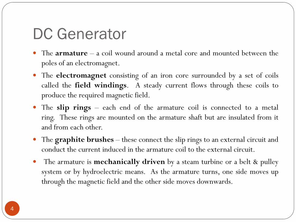
The armature – a coil wound around a metal core and mounted between the
poles of an electromagnet.
The electromagnet consisting of an iron core surrounded by a set of coils
called the field windings. A steady current flows through these coils to
produce the required magnetic field.
The slip rings – each end of the armature coil is connected to a metal
ring. These rings are mounted on the armature shaft but are insulated from it
and from each other.
The graphite brushes – these connect the slip rings to an external circuit and
conduct the current induced in the armature coil to the external circuit.
The armature is mechanically driven by a steam turbine or a belt & pulley
system or by hydroelectric means. As the armature turns, one side moves up
through the magnetic field and the other side moves downwards.

DC Generator
5
The coil thus experiences a change of magnetic flux with time. The result is
that an emf is induced in one direction in one side of the coil and in the other
direction in the other side of the coil.
Thus, these emf’s act in the same sense around the coil. The ends of the coil are
connected to slip rings against which rest graphite brushes. When these brushes
are connected across an external circuit, the induced emf produces an electric
current.
Each time the coil passes through the position where its plane is perpendicular
to the magnetic field lines, the direction of the emf in the coil is
reversed. Hence an alternating current is produced at a frequency equal to
the number of revolutions per second of the armature.

DC Generator
6
An alternating current generator may be converted to a direct current
generator in a couple of ways:
By using a split ring commutator instead of slip rings. The split ring
commutator is mounted on the armature shaft but is insulated from it. The
commutator reverses the connections of the coil to the external circuit each
time the current in the coil reverses. Thus, a DC output is achieved from the
AC generator.
By using a bridge rectifier circuit. This is an arrangement of electronic
components (diodes) that converts the AC output from the generator to a DC
output.
Note that in an electric current generator, mechanical energy is
transformed into electrical energy. In an electric current motor,
electrical energy is transformed into mechanical energy.

DC Generator
7

DC Generator
8

DC Generator
9

DC Generator
10

DC Generator
11

DC Generator
12

Armature Reaction
13
The effect of magnetic field set up by armature current on the distribution of flux under main poles of a generator. The armature magnetic field has two effects:
It demagnetises or weakens the main flux and
It cross-magnetises or distorts it.

Armature Reaction
14
Fig above shows the flux distribution of a bipolar generator when there is no
current in the armature conductors.
The brushes are touching the armature conductors directly, although in
practice, they touch commutator segments, it is seen that:
(a) the flux is distributed symmetrically with respect to the polar axis, which is
the line joining the centres of NS poles.
(b) The magnetic neutral axis (M.N.A.) coincides with the geometrical neutral
axis (G.N.A.).
Magnetic neutral axis may be defined as the axis along which no emf is produced in the
armature conductors because they move parallel to the lines of flux.
OR
M.N.A. is the axis which is perpendicular to the flux passing through the armature.

Armature Reaction
15
Brushes are always placed along M.N.A. Hence, M.N.A. is also called ‘axis of commutation’ because reversal of current in armature conductors takes place across this axis.
Vector OFm which represents, both magnitude and direction, the mmf of producing the main flux.
Fig below shows the field (or flux) set up by the armature conductors alone when carrying current, the field coils being unexcited. The current direction is downwards in conductors under N-pole and upwards in those under S-pole.

Armature Reaction
16
The armature mmf (depending on the strength of the armature current) is
shown separately both in magnitude and direction by the vector OFA. Under
actual load conditions, the two mmf exist simultaneously in the generator as
shown in figure below.
It is seen that the flux through the armature is no longer uniform and
symmetrical about the pole axis, rather it has been distorted.

Armature Reaction
17
The flux is seen to be crowded at the trailing pole tips but weakened or thinned
out at the leading pole tips (the pole tip which is first met during rotation by armature
conductors is known as the leading pole tip and the other as trailing pole tip).
The strengthening and weakening of flux is separately shown for a four-pole
machine in Fig.

Armature Reaction
18
In is shown the resultant mmf OF (The new position of M.N.A.) which is found
by vectorially combining OFm and OFA. And the new position of M.N.A which
is always perpendicular to the resultant mmf vector OF, is also shown in the
figure. 0
With the shift of M.N.A., say through an angle θ brushes are also shifted so as
to lie along the new position of M.N.A. Due to this brush shift , the armature
conductors and hence armature current is redistributed.
All conductors to the left of new position of M.N.A. but between the two
brushes, carry current downwards and those to the right carry current
upwards. The armature mmf is found to lie in the direction of the new position
of M.N.A. (or brush axis). The armature mmf is now represented by the vector
OFA.

Armature Reaction
19
OFA can now be resolved into two rectangular components, OFd parallel to
polar axis and OFC perpendicular to this axis.
We find that: (i) Component OFC is at right angles to the vector OFm
representing the main mmf It produces distortion in the main field and is hence
called the cross-magnetising or distorting component of the armature reaction.
(ii) The component OFd is in direct opposition of OFm which represents the
main mmf It exerts a demagnetising influence on the main pole flux. Hence, it
is called the demagnetising or weakening component of the armature reaction.
It should be noted that both distorting and demagnetising effects will increase
with increase in the armature current.
Armature Reaction
20
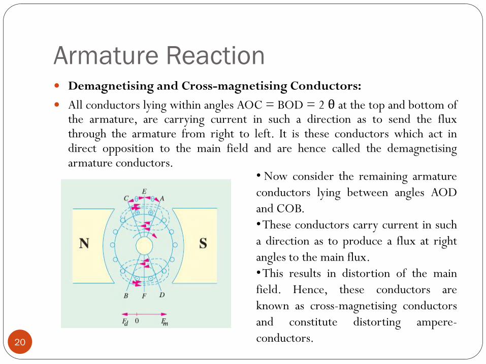
Demagnetising and Cross-magnetising Conductors:
All conductors lying within angles AOC = BOD = 2 θ at the top and bottom of the armature, are carrying current in such a direction as to send the flux through the armature from right to left. It is these conductors which act in direct opposition to the main field and are hence called the demagnetising armature conductors.
• Now consider the remaining armature
conductors lying between angles AOD
and COB.
• These conductors carry current in such
a direction as to produce a flux at right
angles to the main flux.
• This results in distortion of the main
field. Hence, these conductors are
known as cross-magnetising conductors
and constitute distorting ampere-
conductors.
Armature Reaction
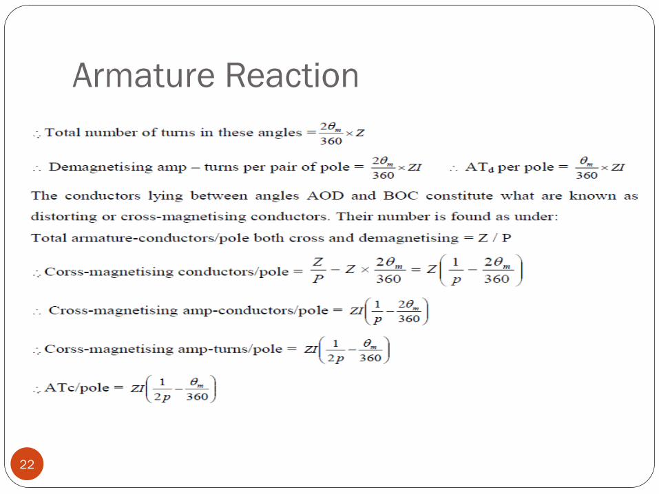
21
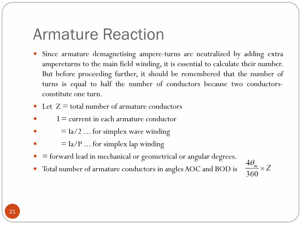
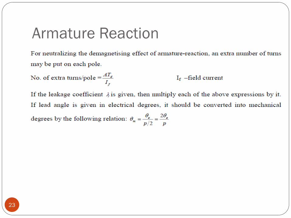
Since armature demagnetising ampere-turns are neutralized by adding extra
ampereturns to the main field winding, it is essential to calculate their number.
But before proceeding further, it should be remembered that the number of
turns is equal to half the number of conductors because two conductors-
constitute one turn.
Let Z = total number of armature conductors
I = current in each armature conductor
= Ia/2 ... for simplex wave winding
= Ia/P ... for simplex lap winding
= forward lead in mechanical or geometrical or angular degrees.
Total number of armature conductors in angles AOC and BOD is
Armature Reaction
22
Armature Reaction
23

Armature Reaction
24
Compensating Windings:
These are used for large direct current machines which are subjected to large
fluctuations in load i.e. rolling mill motors and turbo-generators etc.
Their function is to neutralize the cross magnetizing effect of armature
reaction. In the absence of compensating windings, the flux will be suddenly
shifting backward and forward with every change in load.
This shifting of flux will induce statically induced emf in the armature coils. The
magnitude of this emf will depend upon the rapidity of changes in load and the
amount of change. It may be so high as to strike an the consecutive commutator
segments across the top of the mica sheets separating them.
This may further develop into a flashover around the whole commutator
thereby short-circuiting the whole armature.
Armature Reaction
25
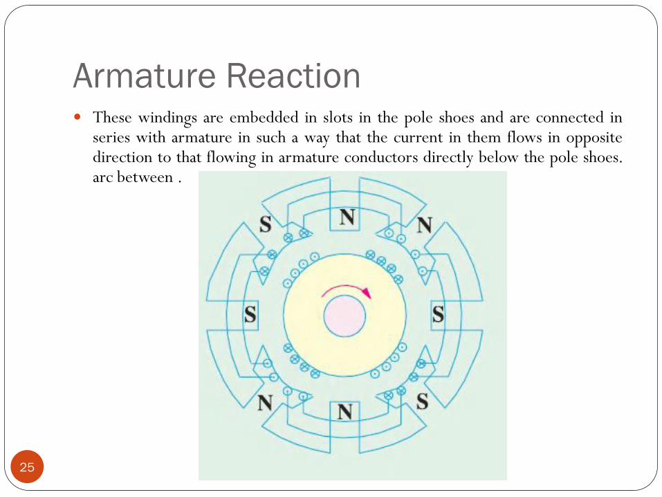
These windings are embedded in slots in the pole shoes and are connected in series with armature in such a way that the current in them flows in opposite direction to that flowing in armature conductors directly below the pole shoes. arc between .

Armature Reaction
26

Commutation
27
Commutation: the currents induced in armature conductors of a d.c.
generator are alternating. These currents flow in one direction when armature
conductors are under N-pole and in the opposite direction when they are under
S-pole.

Commutation
28
As conductors pass out of the influence of a N-pole and enter that of S-pole, the
current in them is reversed. This reversal of current takes place along magnetic
neutral axis or brush axis i.e. when the brush spans and hence short-circuits
that particular coil undergoing reversal of current through it.
This process by which current in the short-circuited coil is reversed while it crosses the
M.N.A. is called commutation.
The brief period during which coil remains short-circuited is known as
commutation period Tc. If the current reversal i.e. the change from + I to zero
and then to −I is completed by the end of short circuit or commutation period,
then the commutation is ideal. If current reversal is not complete by that time,
then sparking is produced between the brush and the commutator which results
in progressive damage to both. The brush width is equal to the width of one
commutator segment and one mica insulation.

Commutation
29

Commutation
30
For ideal commutation, current through it should have reversed but it is
carrying 15 A only instead of 20 A.
If the current varies at a uniform rate i.e. if BC is a straight line, then it is
referred to as linear commutation.
However, due to the production of self-induced emf in the coil the variations
follow the dotted curve. It is seen that, in that case, current in coil B has
reached only a value of KF = 15 A in the reversed direction, hence the
difference of 5 A (20-15 A) passes as a spark.
So, we conclude that sparking at the brushes, which results in poor
commutation is due to the inability of the current in the short-circuited coil to
reverse completely by the end of short-circuit period (which is usually of the
order of 1/500 second).
Commutation
31
The main cause which retards or delays this quick reversal is the production of
self-induced emf in the coil undergoing commutation.
It may be pointed out that the coil possesses appreciable amount of self
inductance because it lies embedded in the armature which is built up of a
material of high magnetic permeability. This self-induced emf is known as
reactance voltage.
Method of Improving Commutation :
1. Resistance Commutation
2. EMF Commutation
3. Inter Pole of Compole

Resistance Commutation
32
This method of improving commutation consists of replacing low-resistance Cu
brushes by comparatively high-resistance carbon brushes. When current I from
coil C reaches the commutator segment b, it has two parallel paths open to it.
The first part is straight from bar ‘b’ to the brush and the other parallel path is
via the short-circuited coil B to bar ‘a’ and then to the brush. If the Cu brushes
are used, then there is no inducement for the current to follow the second
longer path, it would preferably follow the first path.
But when carbon brushes having high resistance are used, then current I coming
from C will prefer to pass through the second path. The additional advantages of
carbon brushes are that
(i) they are to some degree self lubricating and polish the commutator and
(ii) should sparking occur, they would damage the commutator less than when
Cu brushes are used.
Resistance Commutation
33
But some of their minor disadvantages are:
(i) Due to their high contact resistance (which is beneficial to spark-less
commutation) a loss of approximately 2 volt is caused. Hence, they are not
much suitable for small machines where this voltage forms an appreciable
percentage loss.
(ii) Owing to this large loss, the commutator has to be made some what larger
than with Cu brushes in order to dissipate heat efficiently without greater rise
of temperature.
(iii) because of their lower current density (about 7-8 A/cm2 as compared to
25-30 A/cm2 for Cu brushes) they need larger brush holders.

EMF Commutation
34
In this method, arrangement is made to neutralize the reactance voltage by
producing a reversing emf in the short-circuited coil under commutation.
This reversing emf, as the name shows, is an emf in opposition to the reactance
voltage and if its value is made equal to the latter, it will completely wipe it off,
thereby producing quick reversal of current in the short-circuited coil which
will result in spark-less commutation.
The reversing emf may be produced in two ways:
(i) either by giving the brushes a forward lead sufficient enough to bring the
short-circuited coil under the influence of next pole of opposite polarity or
(ii) by using interpoles. The first method was used in the early machines but has
now been abandoned due to many other difficulties it brings along with.

Interpole of Compoles
35
These are small poles fixed to the yoke and spaced in between the main poles.
They are wound with comparatively few heavy gauge Cu wire turns and are
connected in series with the armature so that they carry full armature current.
Their polarity, in the case of a generator, is the same as that of the main pole
ahead in the direction of rotation. The function of interpoles is two-fold:
(i) As their polarity is the same as that of the main pole ahead, they induce an
emf in the coil (under commutation) which helps the reversal of current. The
emf induced by the compoles is known as commutating or reversing emf.
The commutating emf neutralizes the reactance emf thereby making
commutation spark-less. With interpoles, spark-less commutation can be
obtained up to 20 to 30% overload with fixed brush position. In fact, interpoles
raise sparking limit of a machine to almost the same value as heating
Interpole of Compoles
36
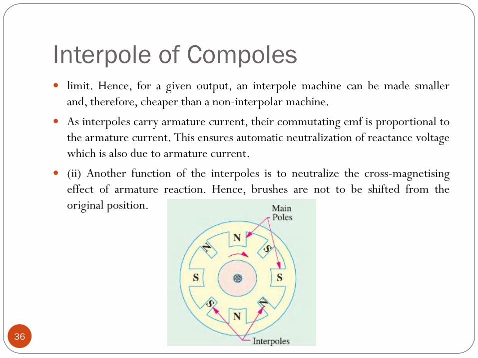
limit. Hence, for a given output, an interpole machine can be made smaller
and, therefore, cheaper than a non-interpolar machine.
As interpoles carry armature current, their commutating emf is proportional to
the armature current. This ensures automatic neutralization of reactance voltage
which is also due to armature current.
(ii) Another function of the interpoles is to neutralize the cross-magnetising
effect of armature reaction. Hence, brushes are not to be shifted from the
original position.

Interpole of Compoles
37
OF as before, represents the mmf due to main poles. OA represents the cross-
magnetising mmf due to armature. BC which represents mmf due to interpoles,
is obviously in opposition to OA, hence they cancel each other out. This
cancellation of cross-magnetisation is automatic and for all loads because both
are produced by the same armature current.
The distinction between the interpoles and compensating windings should be
clearly understood. Both are connected in series and thier m.m.fs. are such as
to neutralize armature reaction. But compoles additionally supply mmf for
counteracting the reactance voltage induced in the coil undergoing
commutation.
Moreover, the action of the compoles is localized; they have negligible effect on
the armature reaction occurring on the remainder of the armature periphery.

Queries ?
38

39