Embed Size (px)
Citation preview

1
CONTENTS CHAPTER PAGE NO.
1. Abstract………………………………………………………………………………. 3
2. Introduction…………………………………………………………………………. 4

2
3. Physics of optical fibers………………………………………………………… 5
4. Advantage of fiber optic system…………………………………………………. 8
5. Fiber optic Transmission system ………………………………………………. 9
6. How are optical fibers made………………………………………………………. 16
7. Applications…………………………………………………………………………….
8. How are major under sea cables laid in the ocean? ………………………….
9. Conclusion……………………………………………………………………………..
10. Bibliography………………………………………………………………………….
11. Appendix………………………………………………………………………………
1. Abstract
Optical Fiber communications form a crucial role in exchanging information globally. The development of optical
fibers made a revolution starting from a small fiber to a cable of wires connecting countries continently. This
seminar first instigates the fundamentals of physics involved in the optical fiber. Secondly, explains about the
heart of the seminar “Optical Fibers communication system” and its related components. Special care is taken to
elaborate its usage in Switching and access networks. The benefits drawn through this communication is briefed

3
to emphasize its impact. Finally, it deals with the manufacture of optical fibers and an idea prompted about the
undersea cable system.
2. INTRODUCTION
The 21st century, the era of ‘Information technology’, this is the outcome of many brilliant inventions and
discoveries. Progressing from the copper wire of a century ago to today’s fiber optic cable , our increasing ability
to transmit more information, more quickly and over longer distances has expanded the boundaries of our
technological development in all areas.
4
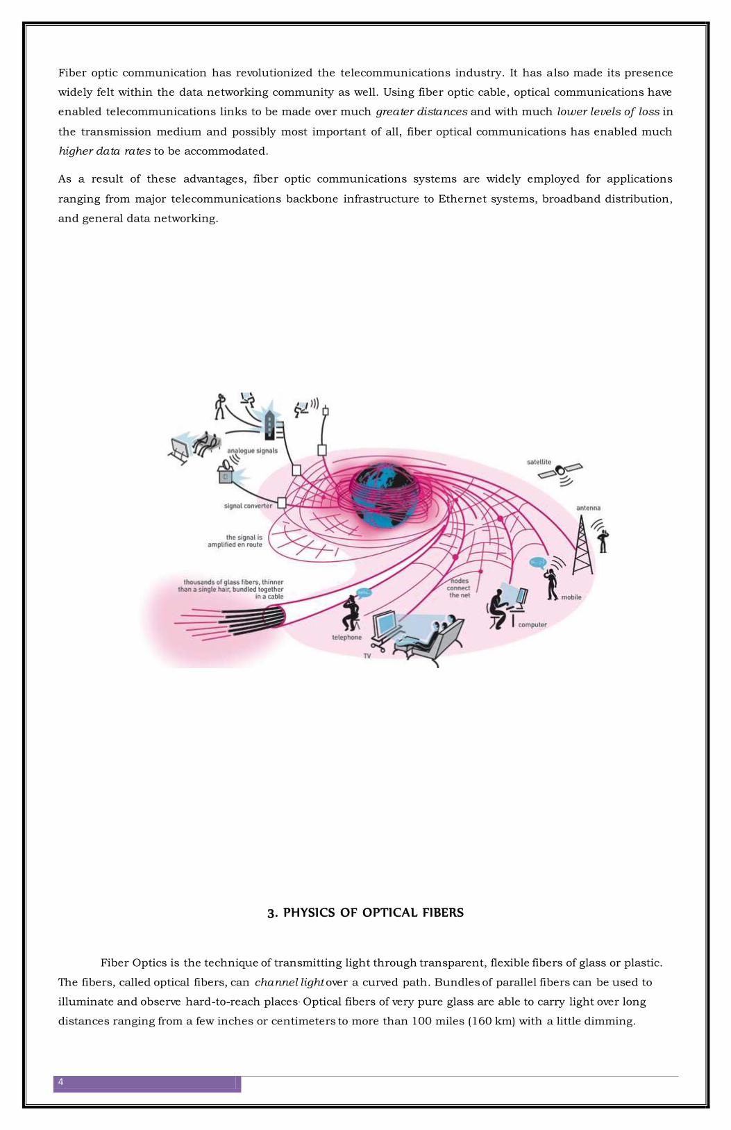
Fiber optic communication has revolutionized the telecommunications industry. It has also made its presence
widely felt within the data networking community as well. Using fiber optic cable, optical communications have
enabled telecommunications links to be made over much greater distances and with much lower levels of loss in
the transmission medium and possibly most important of all, fiber optical communications has enabled much
higher data rates to be accommodated.
As a result of these advantages, fiber optic communications systems are widely employed for applications
ranging from major telecommunications backbone infrastructure to Ethernet systems, broadband distribution,
and general data networking.
3. PHYSICS OF OPTICAL FIBERS
Fiber Optics is the technique of transmitting light through transparent, flexible fibers of glass or plastic.
The fibers, called optical fibers, can channel light over a curved path. Bundles of parallel fibers can be used to
illuminate and observe hard-to-reach places. Optical fibers of very pure glass are able to carry light over long
distances ranging from a few inches or centimeters to more than 100 miles (160 km) with a little dimming.
5
Cables containing such fibers are used in certain types of communications systems. Some individual fibers are
thinner than human hair and measure less than 0.00015 inch (0.004 mm) in diameter.
3.1 Optical Fiber cable construction:
If you look closely at a basic single optical f iber, you will see that it has the following parts:
Core - Thin glass center of the fiber where the light travels
Cladding - Outer optical material surrounding the core that reflects the light back into the core
Buffer coating - Plastic coating that protects the fiber from damage and moisture
Hundreds or thousands of these optical fibers are arranged in bundles in optical cables. The bundles are
protected by the cable's outer covering, called a jacket.
Basic optical fiber is ideal for most inter-building applications where extreme ruggedness is not required. In
addition to the “basic” variety, it is also available for just about any application, including direct buried, armored,
rodent resistant cable with steel outer jacket, and UL approved plenum grade cable. Color-coded, multi-fiber
cable is also available.
3.2 Principle operation:
Fiber optics is based on the optical phenomenon known as total internal reflection [A-1]. This causes the fiber to
act as a waveguide. With the simplest form of optical fiber, light entering one end of the fiber strikes the
boundary of the fiber and is reflected inward. The light travels through the fiber in a succession of zigzag
reflections until it exits from the other end of the fiber. Other forms of optical fibers are designed in such a way
that the zigzagging of the light is greatly reduced or virtually eliminated.
3.3 Optical fiber types
Optical fibers can also be split into single mode fiber, and multimode fiber. Mention of both single mode fiber and
multi-mode fiber is often seen in the literature.
3.3.1 Multimode fiber:
a) Step Index: Core and cladding materials have uniform but different refractive index.
b) Graded Index: Core material has variable index as a function of the radial distance from the center.
This form of fiber has a greater diameter than single mode fiber, being typically around 50 microns in
diameter, and this makes them easier to manufacture than the single mode fibers. It can capture light
from the light source and pass it to the receiver with a high level of efficiency. As a result it can be used
with low cost light emitting diodes
It also suffers from multi-mode modal dispersion and this severely limits the usable bandwidth. As a result
it has not been widely used since the mid 1980s. Single mode fiber cable is the preferred type.
WDM is not normally used on multi-mode fiber
Driven by LEDs and most commonly used for short and medium length point-to-point transmission systems.
Multimode fiber gives you high bandwidth at high speeds (10 to 100MBS - Gigabit to 275m to 2km) over
medium distances. , in long cable runs (greater than 3000 feet [914.4 meters), multiple paths of light can
cause signal distortion at the receiving end, resulting in an unclear and incomplete data transmission so
designers now call for single mode fiber in new applications using Gigabit and beyond.
3.3.2 Single mode fiber: (Mono/Uni-mode optical fiber, Single-mode optical waveguide)
Typically single mode fiber core are around eight to ten microns in diameter, much smaller than a hair. The
core diameter is almost equal to the wavelength of the emitted light. So that it propagates along a single
path.
No multi-modal dispersion means that it has a much wider bandwidth.
6
WDM is normally employed in single mode fiber.
The main limitation to the bandwidth: Chromatic dispersion where different colors, i.e. Wavelengths
propagate at different speeds. Chromatic dispersion of the optical fiber cable occurs within the centre of
the fiber itself.
Note: It is found that it is negative for short wavelengths and changes to become positive at longer
wavelengths. As a result there is a wavelength for single mode fiber where the dispersions are zero. This
generally occurs at a wavelength of around 1310 nm and this is the reason why this wavelength is widely
used. (Obtained by solutions to Maxwell’s Equations and Bessel Functions)
The disadvantage of single mode fiber is that it requires high tolerance to be manufactured and this
increases its cost. Against this the fact that it offers superior performance, especially for long runs means
that much development of single mode fiber has been undertaken to reduce the costs.
Driven by a laser diode and is most often used for long distance telecommunications purposes.
3.4 Attenuation of Optical Fibres
The loss of power in light in an optical fiber is measured in decibels (dB). Fiber optic cable specifications express
cable loss as attenuation per 1-km length as dB/km. This value is multiplied by the total length of the optical
fiber in kilometers to determine the fiber's total loss in dB.
Optical fiber light loss is caused by a number of factors that can be categorized into extrinsic and intrinsic
losses:
3.4.1 Extrinsic
i) Bending loss: Bend loss occurs at fiber cable bends that are tighter than the cable's minimum bend radius.
Bending loss can also occur on a smaller scale from such factors as:
Sharp curves of the fiber core.
Displacements of a few millimeters or less, caused by buffer or jacket imperfections.
Poor installation practice
This light power loss, called microbending, can add up to a significant amount over a long distance
ii) Splice and connector loss: Splice loss occurs at all splice locations. Mechanical splices usually have the
highest loss, commonly ranging from 0.2 to over 1.0 dB, depending on the type of splice. Fusion splices have
lower losses, usually less than 0.1 dB. A loss of 0.05 dB or less is usually achieved with good equipment and
an experienced splicing crew. High loss can be attributed to a number of factors, including:
Poor cleave.
Misalignment of fiber cores.
An air gap. Contamination.
Index-of-refraction mismatch.
Core diameter mismatch
Losses at fiber optic connectors commonly range from 0.25 to over 1.5 dB and depend greatly on the type of
connector used. Other factors that contribute to the connection loss include:
Dirt or contaminants on the connector (very common).
Improper connector installation.
A damaged connector face.
7
Poor scribe (cleave).
Mismatched fiber cores.
Misaligned fiber cores.
Index-of-refraction mismatch
3.4.2 Intrinsic
i) Loss inherent to fiber: Light loss in a fiber that cannot be eliminated during the fabrication process is due to
impurities in the glass and the absorption of light at the molecular level. Loss of light due to variations in
optical density, composition, and molecular structure is called Rayleigh scattering. Rays of light encountering
these variations and impurities are scattered in many directions and lost.
The absorption of light at the molecular level in a fiber is mainly due to contaminants in glass such as water
molecules (OH-). The ingress of OUT molecules into an optical fiber is one of the main factors contributing to the
fiber's increased attenuation in aging. Silica glass's (Si02) molecular resonance absorption also contributes to
some light loss.
ii) Loss resulting from fiber fabrication: Irregularities during the manufacturing process can result in the loss
of light rays. For example, a 0.1 percent change in the core diameter can result in a 10-dB loss per kilometer.
Precision tolerance must be maintained throughout the manufacturing of the fiber to minimize losses.
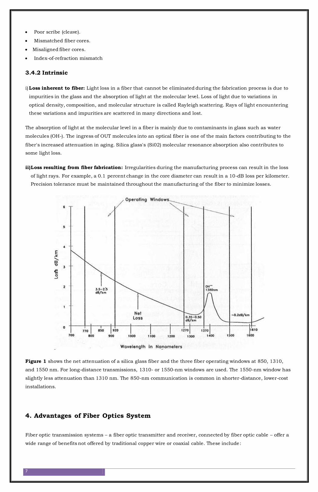
Figure 1 shows the net attenuation of a silica glass fiber and the three fiber operating windows at 850, 1310,
and 1550 nm. For long-distance transmissions, 1310- or 1550-nm windows are used. The 1550-nm window has
slightly less attenuation than 1310 nm. The 850-nm communication is common in shorter-distance, lower-cost
installations.
4. Advantages of Fiber Optics System
Fiber optic transmission systems – a fiber optic transmitter and receiver, connected by fiber optic cable – offer a
wide range of benefits not offered by traditional copper wire or coaxial cable. These include:
8
1. Less expensive - Several miles of optical cable can be made cheaper than equivalent lengths of copper wire.
This saves your provider (cable TV, Internet, etc) and your money.
2. Thinner – (Light Weight) A fiber optic cable, even one that contains many fibers, is usually much smaller
and lighter in weight than a wire or coaxial cable with similar information carrying capacity. It is easier to
handle and install, and uses less duct space. (It can frequently be installed without ducts.)
3. Higher carrying capacity- This has the ability to carry much more information and deliver it with greater
fidelity than either copper wire or coaxial cable. This allows more phone lines to go over the same cable or
more channels to come through the cable into your cable TV box.
4. Less signal degradation - The loss of signal in optical fiber is less than in copper wire. The fiber is totally
immune to virtually all kinds of interference, including lightning, and will not conduct electricity. It can
therefore come in direct contact with high voltage electrical equipment and power lines. It will also not create
ground loops of any kind.
5. Light signals - Unlike electrical signals in copper wires, light signals from one fiber do not interfere with
those of other fibers in the same cable. This means clearer phone conversations or TV reception.
6. Low power - Because signals in optical fibers degrade less, lower-power transmitters can be used instead of
the high-voltage electrical transmitters needed for copper wires. Again, this saves your provider and your
money.
7. Digital signals - Fiber optic cable can support much higher data rates, and at greater distances, than coaxial
cable, making it ideal for transmission of serial digital data (information) in computer networks.
8. Non-flammable - Because no electricity is passed through optical fibers, there is no fire hazard. Moreover,
the only carrier in the fiber is light; there is no possibility of a spark from a broken fiber. Even in the most
explosive of atmospheres, there is no fire hazard, and no danger of electrical shock to personnel repairing
broken fibers.
9. No corrosion: As the basic fiber is made of glass, it will not corrode and is unaffected by most chemicals. It
can be buried directly in most kinds of soil or exposed to most corrosive atmospheres in chemical plants
without significant concern.
10. Secure: Fiber optic cable is ideal for secure communications systems because it is very difficult to tap but
very easy to monitor. In addition, there is absolutely no electrical radiation from a fiber.
In Compendium:
To give perspective to the incredible capacity that fibers are moving towards, a 10Gbps signal has the ability to
transmit any of the following per second:
1000 books
1,30,000 voice channels
16 HDTV channels or 100 HDTV channels using compression techniques. (An HDTV requires a much higher
bandwidth than today’s standard television)
Because of these advantages, you see fiber optics in many industries, most notably telecommunications and
computer networks. For example, if you telephone Europe from the United States (or vice versa) and the signal is
bounced off a communications satellite, you often hear an echo on the line. But with transatlantic fiber-optic
cables, you have a direct connection with no echoes.
How are fiber optic cables able to provide all of these advantages? This seminar will provide an overview of f iber
optic technology – with sections devoted to each of the three system components – transmitters, receivers, and the
fiber cable itself. An appreciation of the underlying technology will provide a useful framework for understanding
the reasons behind its many benefits.
5. Fiber Optic Transmission System:
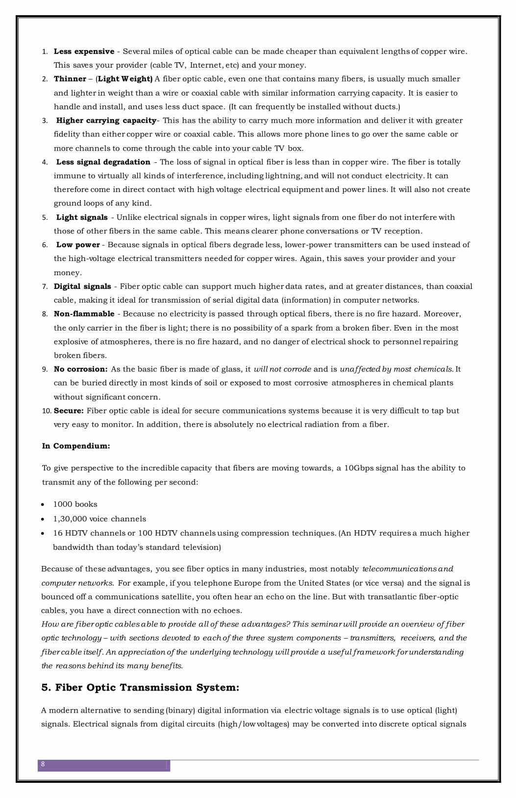
A modern alternative to sending (binary) digital information via electric voltage signals is to use optical (light)
signals. Electrical signals from digital circuits (high/low voltages) may be converted into discrete optical signals
9
(light or no light) with LEDs or solid-state lasers. Likewise, light signals can be translated back into electrical
form through the use of photodiodes or phototransistors for introduction into the inputs of gate circuits.
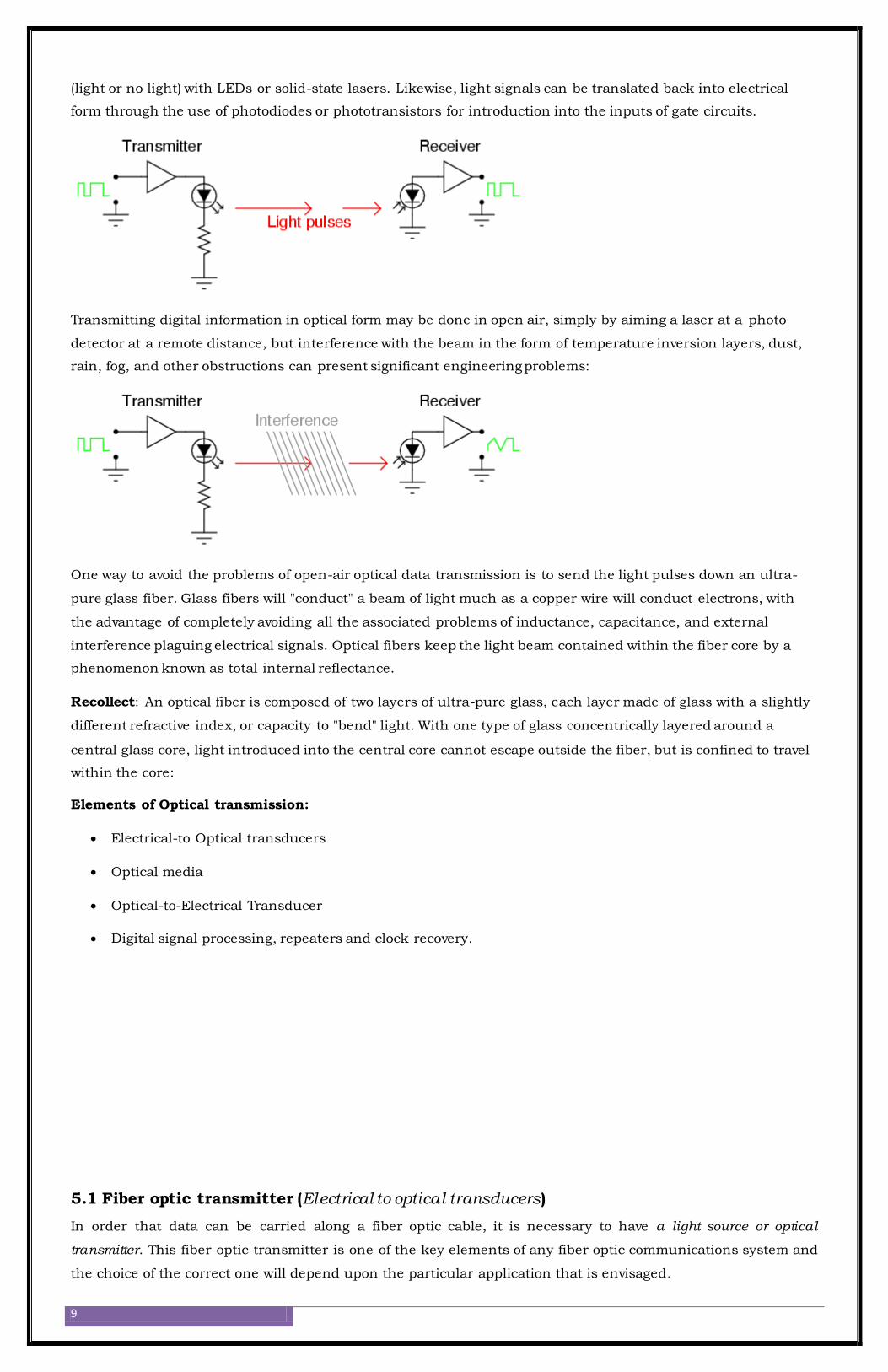
Transmitting digital information in optical form may be done in open air, simply by aiming a laser at a photo
detector at a remote distance, but interference with the beam in the form of temperature inversion layers, dust,
rain, fog, and other obstructions can present significant engineering problems:
One way to avoid the problems of open-air optical data transmission is to send the light pulses down an ultra-
pure glass fiber. Glass fibers will "conduct" a beam of light much as a copper wire will conduct electrons, with
the advantage of completely avoiding all the associated problems of inductance, capacitance, and external
interference plaguing electrical signals. Optical fibers keep the light beam contained within the fiber core by a
phenomenon known as total internal reflectance.
Recollect: An optical fiber is composed of two layers of ultra-pure glass, each layer made of glass with a slightly
different refractive index, or capacity to "bend" light. With one type of glass concentrically layered around a
central glass core, light introduced into the central core cannot escape outside the fiber, but is confined to travel
within the core:
Elements of Optical transmission:
Electrical-to Optical transducers
Optical media
Optical-to-Electrical Transducer
Digital signal processing, repeaters and clock recovery.
5.1 Fiber optic transmitter (Electrical to optical transducers)
In order that data can be carried along a fiber optic cable, it is necessary to have a light source or optical
transmitter. This fiber optic transmitter is one of the key elements of any fiber optic communications system and
the choice of the correct one will depend upon the particular application that is envisaged.
10
How is an electrical AV signal converted into an optical AV signal?
An electrical AV signal is converted into an optical AV signal using an optical transmitter or an electrical-to-
optical converter. An optical transmitter uses a laser diode as the light source, varying the intensity of the laser
light in accordance with the electrical signal. For an analog signal, the intensity of the light source varies with
the voltage or current of the electrical signal. For digital signals, the light intensity is high or low, which
represents logical ones or zeros.
5.2 Optical Transmitter Specifications:
Power level: It is obvious that the fiber optic transmitter should have a sufficiently high level of light output for the
light to be transmitted along the fiber optic cable to the far end. Some fiber optic cable lengths may only be a few
meters or tens of meters long, whereas others may extend for many kilometers. In the case of the long lengths, the
power of the fiber optic transmitter is of great importance.
Type of light: Light can be split into two categories, namely coherent and incoherent light. Essentially, coherent light
has a single frequency, whereas incoherent light contains a wide variety of light packets all containing different
frequencies, i.e. there is no single frequency present. While some emitters may appear to emit a single color, they can
still be incoherent because the light output is centered on a given frequency or wavelength.
The frequency or wavelength of the light: Often fiber optic systems will operate around a given wavelength.
Typically the wavelength of operation is given.
The rate at which the transmitter can be modulated: this affects the data rate for the overall transmission. In
some instances low rate systems may only need to carry data at a rate of a few Mbps, whereas main
telecommunications links need to transmit data at many Gaps.
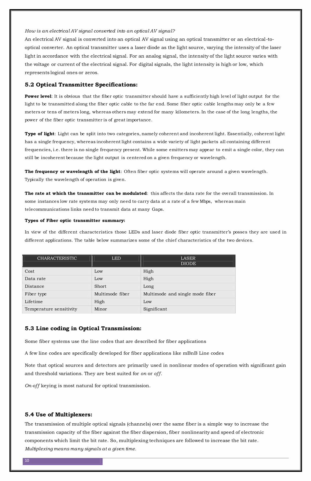
Types of Fiber optic transmitter summary:
In view of the different characteristics those LEDs and laser diode fiber optic transmitter’s posses they are used in
different applications. The table below summarizes some of the chief characteristics of the two devices.
CHARACTERISTIC LED LASER
DIODE
Cost Low High
Data rate Low High
Distance Short Long
Fiber type Multimode fiber Multimode and single mode fiber
Lifetime High Low
Temperature sensitivity Minor Significant
5.3 Line coding in Optical Transmission:
Some fiber systems use the line codes that are described for fiber applications
A few line codes are specifically developed for fiber applications like mBnB Line codes
Note that optical sources and detectors are primarily used in nonlinear modes of operation with significant gain
and threshold variations. They are best suited for on or off.
On-off keying is most natural for optical transmission.
5.4 Use of Multiplexers:
The transmission of multiple optical signals (channels) over the same fiber is a simple way to increase the
transmission capacity of the fiber against the fiber dispersion, fiber nonlinearity and speed of electronic
components which limit the bit rate. So, multiplexing techniques are followed to increase the bit rate.
Multiplexing means many signals at a given time.
11
Suppose for each channel the bit rate is 100 Gb/s and by accommodating 100 channels through multiplexing
technique the total bit rate through a single fiber can be increased to 10 Tbps (1 Tera =1012). Thus the
information carrying capacity of a fiber is increased by the multiplexing technique. There are three types of
multiplexing techniques:
(i) TDM – time division multiplexing
(ii) FDM – frequency division multiplexing
(iii) WDM – wavelength division multiplexing
TDM and FDM techniques are operated in the electrical domain and are widely used in the conventional radio
wave communication. WDM technique is very useful in the optical domain and by WDM; the bit rate can be
increased beyond 10 Tb/s in the optical fiber communication.
Figure 9 shows the basic principle of WDM technique. Here different wavelengths carrying separate signals are
multiplexed by the multiplexer and then they are transmitted through a single fiber. At the receiver end, the
separate signals at different wavelengths are demultiplexed by the demultiplexer and are given to separate
receivers. From the receiver side also the signals can be transmitted in the same manner through the same fiber.
Thus instead of handling a single channel with single wavelength and limited bit rate (10 Gb/s), the bit rate is
raised to about 10 Tb/s, hence the information capacity of the fiber is increased by WDM technique.
5.5 SONET
SONET (Synchronous Optical Network) is a US standard for the internal operation of telephone company
optical networks. It is closely related to a system called SDH (Synchronous Digital Hierarchy) adopted by
the CCITT (now the ITU-T) as a recommendation for the internal operation of carrier (PTT) optical networks
worldwide.
Note: Despite the name, SONET is not an optical networking system. It is an electronic networking system
designed to use optical link connections.
SONET and SDH are of immense importance for two reasons:
i) They offer vast cost savings in public communications networks by redefining the system of channel
multiplexing. This is achieved through time division multiplexing of user data channels throughout
the network. SONET/SDH offers a significantly better method of doing this.
ii) Management of the cable plant. Within a typical telephone company there are many end-user service
offerings. Each of these is a network in its own rite (including and especially the telephone network).
Each of these networks needs link connections of various speeds connecting nodes (central offices)
at arbitrary points around the country. However the company wants to manage and share its cable
plant as a single entity.
Sonet Protocol Structure:
The basic structure in SONET is a frame of 810 bytes which is sent every 125 µsec. This allows a single byte
within a frame to be part of a 64 kbps digital voice channel. Since the minimum frame size is 810 bytes then the
minimum speed at which SONET will operate is 51.84 megabits per second.
810 bytes ×8000 frames/sec ×8 (bits) = 51.84 megabits/sec. This basic frame is called the Synchronous
Transport Signal level 1 (STS-1), which is an electrical signal. The diagrammatic representation of the frame as a
square is done for ease of understanding. The 810 bytes are transmitted row by row starting from the top left of
the diagram. One frame is transmitted every 125 µsec.
5.6 Fiber optic splicing
This method is similar to connectors. A fiber optic splice is defined by the fact that it gives a permanent or
relatively permanent connection between two fiber optic cables.
There are many occasions when fiber optic splices are needed. One of the most common occurs when a fiber
optic cable that is available is not sufficiently long for the required run. In this case it is possible to splice
12
together two cables to make a permanent connection. As fiber optic cables are generally only manufactured in
lengths up to about 5 km, when lengths of 10 km are required, for example, then it is necessary to splice two
lengths together.
Fiber optic splices can be undertaken in two ways:
1) Mechanical splices:
The mechanical splices are normally used when splices need to be made quickly and easily.
Operation:
It is necessary to strip back the outer protective layer on the fiber optic cable, clean it and then perform a
precision cleave or cut. When cleaving (cutting) the fiber optic cable it is necessary to obtain a very clean cut, and
one in which the cut on the fiber is exactly at right angles to the axis of the fiber.
Once cut the ends of the fibers to be spliced are placed into a precision made sleeve. They are accurately aligned
to maximize the level of light transmission and then they are clamped in place. A clear, index matching gel may
sometimes be used to enhance the light transmission across the joint.
Mechanical fiber optic splices can take as little as five minutes to make, although the level of light loss is around
ten percent.
2) Fusion Splices:
This type of connection is made by fusing or melting the two ends together. This type of splice uses an electric
arc to weld two fiber optic cables together and it requires specialized equipment to perform the splice. Once the
fiber optic splice has been made, an estimate of the loss is made by the fiber optic splicer. This is achieved by
directing light through the cladding on one side and measuring the light leaking from the cladding on the other
side of the splice.
The equipment that performs these splices provides computer controlled alignment of the optical fibers and it is
able to achieve very low levels of loss, possibly a quarter of the levels of mechanical splices. However this comes
at a process as fusion welders for fiber optic splices are very expensive.
Mechanical and fusion splices:
The two types of fiber optic splices are used in different applications. The mechanical ones are used for
applications where splices need to be made very quickly and where the expensive equipment for fusion splices
may not be available. Some of the sleeves for mechanical fiber optic splices are advertised as allowing connection
and disconnection. In this way a mechanical splice may be used in applications where the splice may be less
permanent.
Fusion splices offer a lower level of loss and a high degree of permanence. However they require the use of the
expensive fusion splicing equipment. In view of this they tend to be used more for the long high data rate lines
that are installed that are unlikely to be changed once installed.
5.7 Optical Couplers

13
5.8 Need for Repeaters:
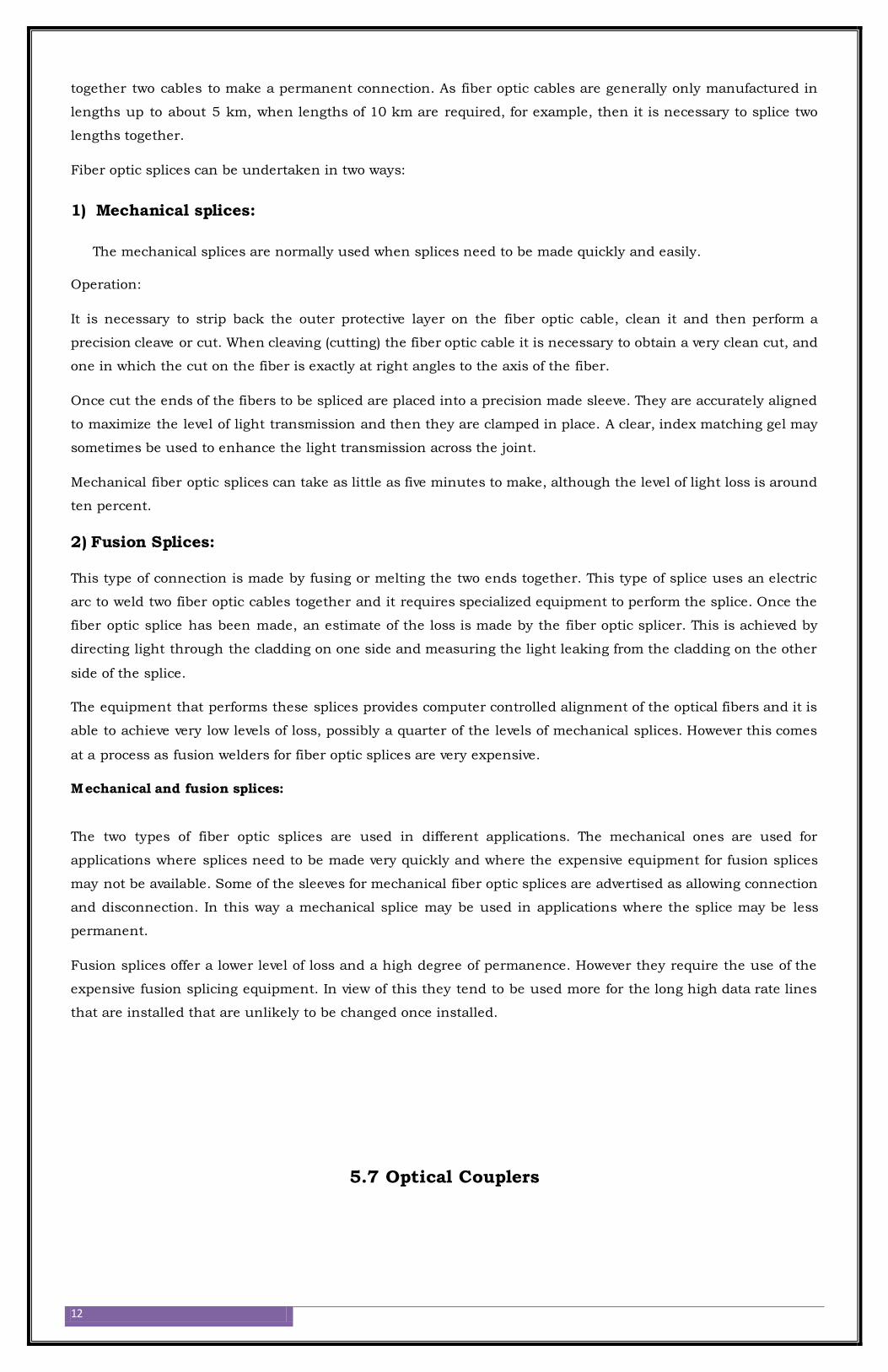
A light pulse emitted by the LED taking a shorter path through the fiber will arrive at the detector sooner
than light pulses taking longer paths. The result is distortion of the square-wave's rising and falling edges,
called pulse stretching. This problem becomes worse as the overall fiber length is increased:
14
However, if the fiber core is made small enough (around 5 microns in diameter), light modes are restricted
to a single pathway with one length. Fiber so designed to permit only a single mode of light is known
as single-mode fiber. Because single-mode fiber escapes the problem of pulse stretching experienced in
long cables, it is the fiber of choice for long-distance (several miles or more) networks. The drawback, of
course, is that with only one mode of light, single-mode fibers do not conduct as much light as multimode
fibers. Over long distances, this exacerbates the need for "repeater" units to boost light power.
5.9 Optical Regenerator:
As mentioned above, some signal loss occurs when the light is transmitted through the fiber, especially over long
distances (more than a half mile, or about 1 km) such as with undersea cables. Therefore, one or more optical
regenerators are spliced along the cable to boost the degraded light signals.
An optical regenerator consists of optical fibers with a special coating (doping). The doped portion is "pumped"
with a laser. When the degraded signal comes into the doped coating, the energy from the laser allows the doped
molecules to become lasers themselves. The doped molecules then emit a new, stronger light signal with the
same characteristics as the incoming weak light signal. Basically, the regenerator is a laser amplifier for the
incoming signal.
5.10 Fiber optical Receiver
Once data has been transmitted across a fiber optic cable, it is necessary for it to be received and converted into
electrical signals so that it can be processed and distributed to its final destination. The fiber optic receiver is the
15
essential component in this process as it performs the actual reception of the optical signal and converts it into
electrical pulses. Within the fiber optic receiver, the photo detector is the key element
A variety of semiconductor photo-detectors may be used as fiber optic receivers. They are normally
semiconductor devices, and a form of photo-diode. A variety of diodes may be used in fiber optic receivers,
namely p-n photodiode, a p-i-n photodiode, or an avalanche photodiode. Metal-semiconductor-metal (MSM)
photo detectors are also used in fiber optic receivers on occasions as well.
Overall receiver
Although the photo-detector is the major element in the fiber optic receiver, are the other elements to the whole
unit. Once the light has been received by the fiber optic receiver and converted into electronic pulses, the signals
are processed by the electronics in the receiver. Typically these will include various forms of amplification
including a limiting amplifier. These serve to generate a suitable square wave that can then be processed in any
logic circuitry that may be required.
Once in a suitable digital format the received signal may undergo further signal processing in the form of a clock
recovery, etc. This will undertaken before the data from the fiber optic receiver is passed on.
Diode performance
One of the keys to the performance of the overall fiber optic receiver is the photodiode itself. The response times
of the diodes govern the speed of the data that can be recovered. Although avalanche diodes provide high speed
they are also noisier and require a sufficiently high level of signal to overcome this.
The most common type of diode used is the p-i-n diode. This type of diode gives a greater level of conversion than
a straight p-n diode as the light is converted into carriers in the region at the junction, i.e. between the p and n
regions. The presence of the intrinsic region increases this area and hence the area in which light is converted.
6. How are optical Fibers made?
Now that we know how fiber-optic systems work and why they are useful -- how do they make them? Optical
fibers are made of extremely pure optical glass. We think of a glass window as transparent, but the thicker the
16
glass gets, the less transparent it becomes due to impurities in the glass. However, the glass in an optical fiber
has far fewer impurities than window-pane glass. One company's description of the quality of glass is as follows:
If you were on top of an ocean that is miles of solid core optical fiber glass, you could see the bottom clearly.
Making optical fibers requires the following steps:
1. Making a preform glass cylinder
2. Drawing the fibers from the preform
3. Testing the fibers
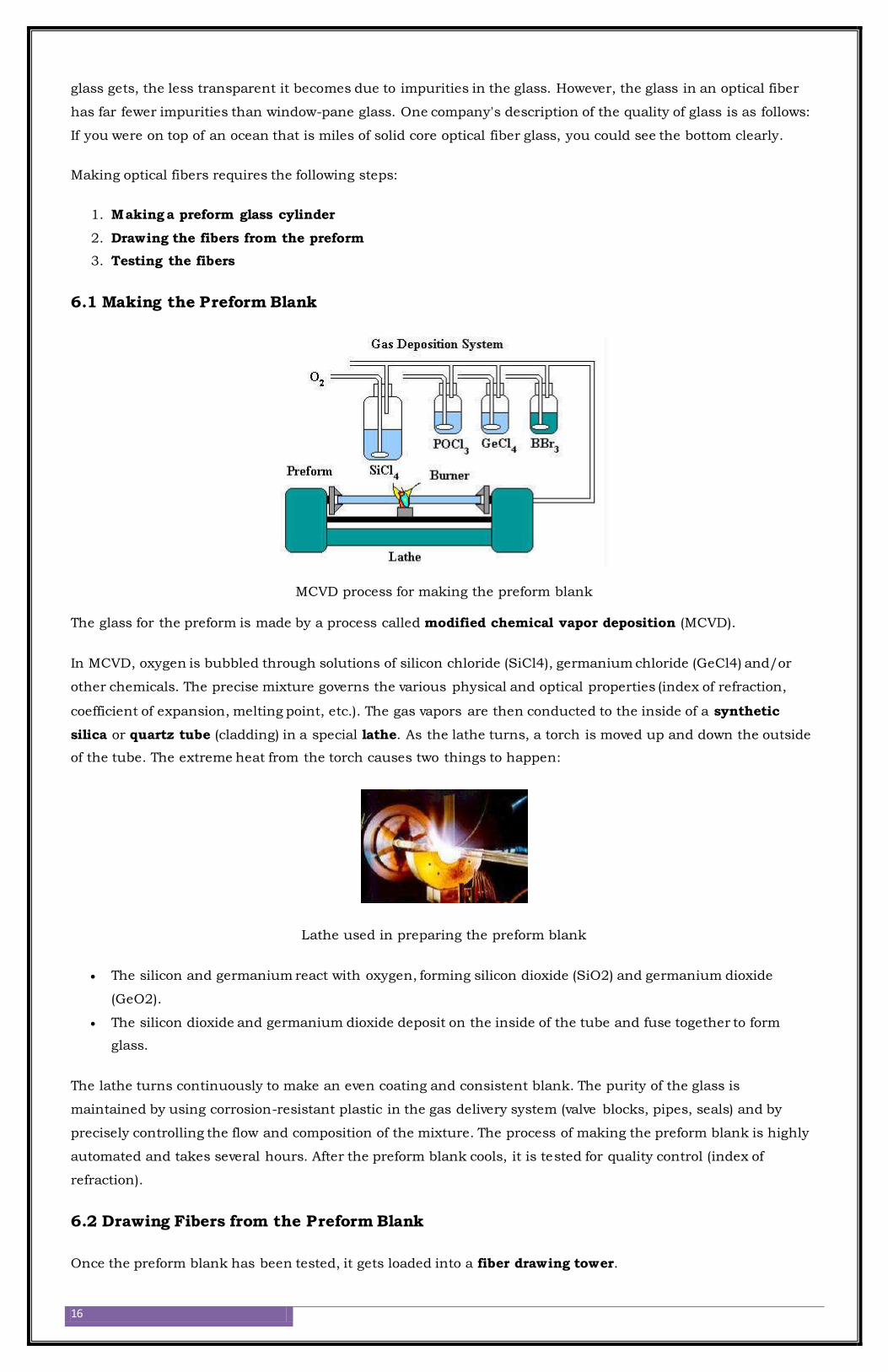
6.1 Making the Preform Blank
MCVD process for making the preform blank
The glass for the preform is made by a process called modified chemical vapor deposition (MCVD).
In MCVD, oxygen is bubbled through solutions of silicon chloride (SiCl4), germanium chloride (GeCl4) and/or
other chemicals. The precise mixture governs the various physical and optical properties (index of refraction,
coefficient of expansion, melting point, etc.). The gas vapors are then conducted to the inside of a synthetic
silica or quartz tube (cladding) in a special lathe. As the lathe turns, a torch is moved up and down the outside
of the tube. The extreme heat from the torch causes two things to happen:
Lathe used in preparing the preform blank
The silicon and germanium react with oxygen, forming silicon dioxide (SiO2) and germanium dioxide
(GeO2).
The silicon dioxide and germanium dioxide deposit on the inside of the tube and fuse together to form
glass.
The lathe turns continuously to make an even coating and consistent blank. The purity of the glass is
maintained by using corrosion-resistant plastic in the gas delivery system (valve blocks, pipes, seals) and by
precisely controlling the flow and composition of the mixture. The process of making the preform blank is highly
automated and takes several hours. After the preform blank cools, it is tested for quality control (index of
refraction).
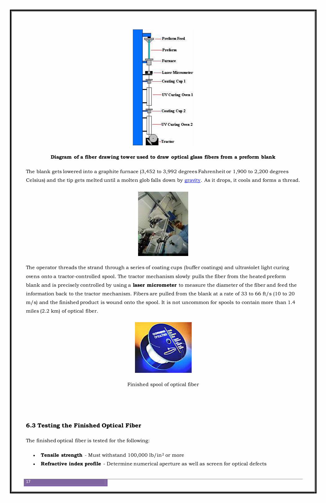
6.2 Drawing Fibers from the Preform Blank
Once the preform blank has been tested, it gets loaded into a fiber drawing tower.
17
Diagram of a fiber drawing tower used to draw optical glass fibers from a preform blank
The blank gets lowered into a graphite furnace (3,452 to 3,992 degrees Fahrenheit or 1,900 to 2,200 degrees
Celsius) and the tip gets melted until a molten glob falls down by gravity. As it drops, it cools and forms a thread.
The operator threads the strand through a series of coating cups (buffer coatings) and ultraviolet light curing
ovens onto a tractor-controlled spool. The tractor mechanism slowly pulls the fiber from the heated preform
blank and is precisely controlled by using a laser micrometer to measure the diameter of the fiber and feed the
information back to the tractor mechanism. Fibers are pulled from the blank at a rate of 33 to 66 ft/s (10 to 20
m/s) and the finished product is wound onto the spool. It is not uncommon for spools to contain more than 1.4
miles (2.2 km) of optical fiber.
Finished spool of optical fiber
6.3 Testing the Finished Optical Fiber
The finished optical fiber is tested for the following:
Tensile strength - Must withstand 100,000 lb/in2 or more
Refractive index profile - Determine numerical aperture as well as screen for optical defects

18
Fiber geometry - Core diameter, cladding dimensions and coating diameter are uniform
Attenuation - Determine the extent that light signals of various wavelengths degrade over distance
Information carrying capacity (bandwidth) - Number of signals that can be carried at one time (multi-
mode fibers)
Chromatic dispersion - Spread of various wavelengths of light through the core (important for bandwidth)
Operating temperature/humidity range
Temperature dependence of attenuation
Ability to conduct light underwater - Important for undersea cables
Once the fibers have passed the quality control, they are sold to telephone companies, cable companies and
network providers. Many companies are currently replacing their old copper-wire-based systems with new fiber-
optic-based systems to improve speed, capacity and clarity.
7. How are major undersea cables laid in the ocean?
Laying of cables in the oceans of our world is a fascinating business. Real men and women toil long and tedious
hours to make this possible.
Submarine cables are laid down by using specially modified ships (sometimes even purpose built ships) that
19
carry the submarine cable on board and slowly lay it out on the seabed as per the charts/plans given by the
cable operator. The ships can carry with them up to 2,000 kilometers length of cable.
Submarine Cable Map
Source: Submarine Cable Map 2014
Depending on the equipment on-board the cable-ship, the type of plough used, the sea conditions and the ocean-
bed where the cable is being laid-down, cable ships can do anywhere from 100-150km of cable laying per day.
Newer ships and ploughs now do about 200 km of cable laying per day.
The ships are commonly referred to as cable-layers or cable-ships.
The cables are specially constructed for submarine operations as they have to endure harsh conditions as well as
pressure.
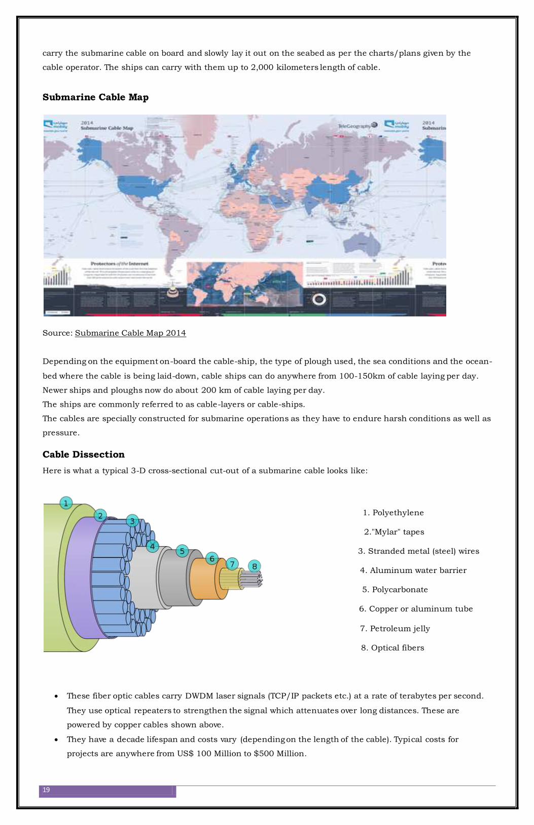
Cable Dissection
Here is what a typical 3-D cross-sectional cut-out of a submarine cable looks like:
1. Polyethylene
2."Mylar" tapes
3. Stranded metal (steel) wires
4. Aluminum water barrier
5. Polycarbonate
6. Copper or aluminum tube
7. Petroleum jelly
8. Optical fibers
These fiber optic cables carry DWDM laser signals (TCP/IP packets etc.) at a rate of terabytes per second.
They use optical repeaters to strengthen the signal which attenuates over long distances. These are
powered by copper cables shown above.
They have a decade lifespan and costs vary (depending on the length of the cable). Typical costs for
projects are anywhere from US$ 100 Million to $500 Million.
20
Appendix 3 - Do private telecommunications companies own the undersea cables that connect the internet across
continents?
We don't use satellites because they can't carry terabytes of data for less than a billion dollars per
communication line.
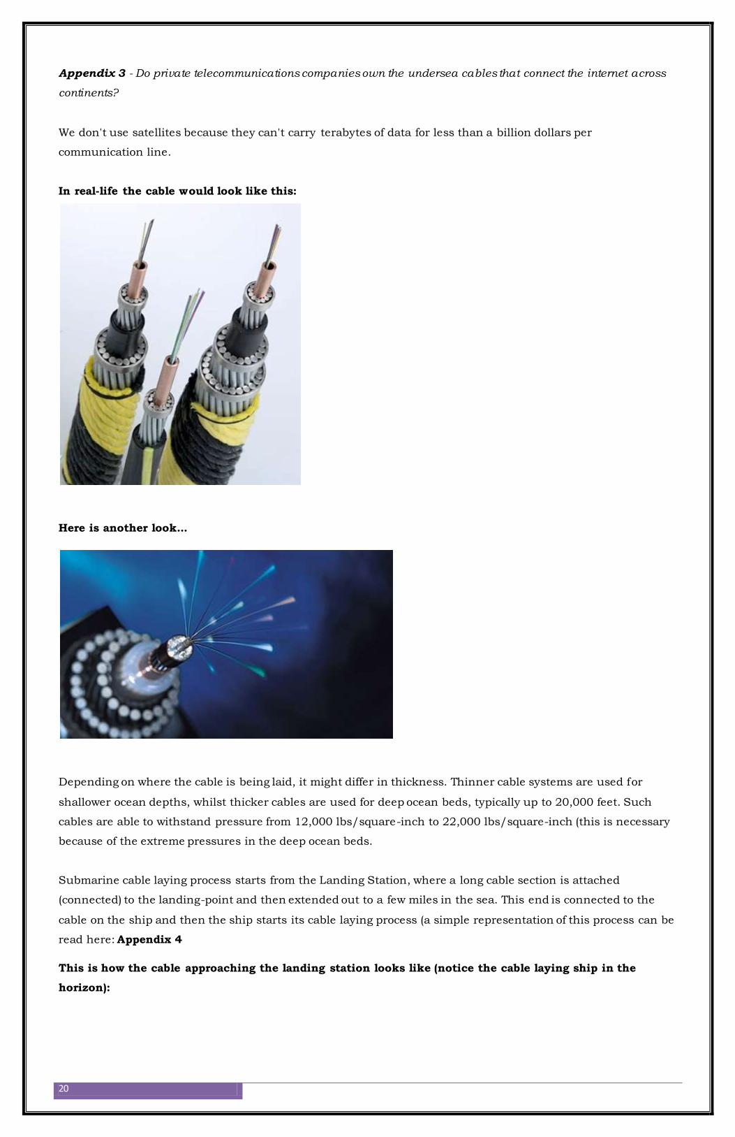
In real-life the cable would look like this:
Here is another look...
Depending on where the cable is being laid, it might differ in thickness. Thinner cable systems are used for
shallower ocean depths, whilst thicker cables are used for deep ocean beds, typically up to 20,000 feet. Such
cables are able to withstand pressure from 12,000 lbs/square-inch to 22,000 lbs/square-inch (this is necessary
because of the extreme pressures in the deep ocean beds.
Submarine cable laying process starts from the Landing Station, where a long cable section is attached
(connected) to the landing-point and then extended out to a few miles in the sea. This end is connected to the
cable on the ship and then the ship starts its cable laying process (a simple representation of this process can be
read here: Appendix 4
This is how the cable approaching the landing station looks like (notice the cable laying ship in the
horizon):

21
Depending on the geography of where the cable is laid out, the cable coming in from the ocean to the landing
station might be advertised or not. Most of the time, it is buried as much as it can be and warning signs are
placed so as to inform everyone that a submarine cable is landing ashore. Most of the time cable consortium
companies try to hide the cable as much as they can, so that only those who need to know, are informed of the
exact route of the cable. This would include municipalities, port authorities and shipping companies.
The market for submarine cables is dominated by Europe (UK, Italy, France, and Germany) and a bit by Japan.
US is overall a small player when compared to the others, as US itself did not have much need to expand cables
to other countries, as much as the other countries had a need to connect to the US.
The ships, which are specialized, are almost all owned by the submarine cable consortium or manufacturers.
These ships are stationed at various points along where the cable extends to ensure that in the event of a cable-
cut, the ships can set sail immediately for cable repairs.
A cable laying ship at port
Cable coiled up in the cargo-hold (the coiling of 100s of miles of cable in the cargo hold is a process that
can take 3 to 4 weeks to complete.
22
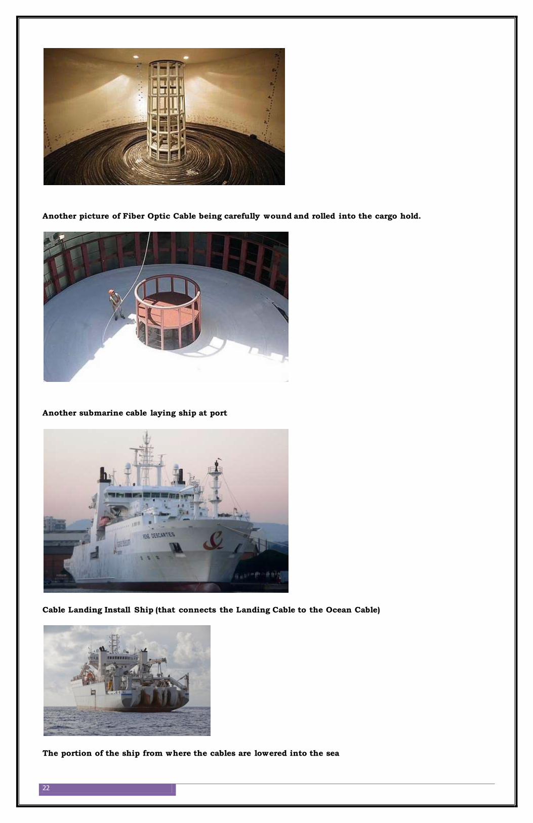
Another picture of Fiber Optic Cable being carefully wound and rolled into the cargo hold.
Another submarine cable laying ship at port
Cable Landing Install Ship (that connects the Landing Cable to the Ocean Cable)
The portion of the ship from where the cables are lowered into the sea
23
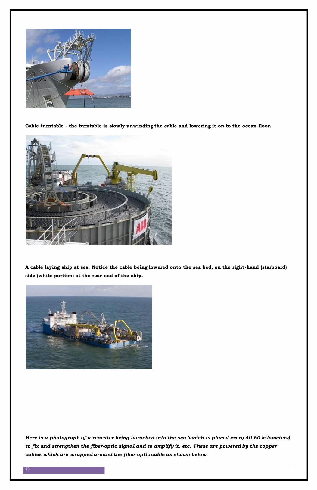
Cable turntable - the turntable is slowly unwinding the cable and lowering it on to the ocean floor.
A cable laying ship at sea. Notice the cable being lowered onto the sea bed, on the right-hand (starboard)
side (white portion) at the rear end of the ship.
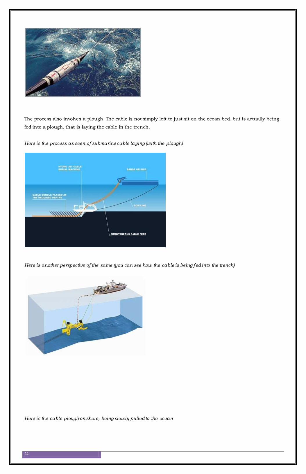
Here is a photograph of a repeater being launched into the sea (which is placed every 40-60 kilometers)
to fix and strengthen the fiber-optic signal and to amplify it, etc. These are powered by the copper
cables which are wrapped around the fiber optic cable as shown below.
24
The process also involves a plough. The cable is not simply left to just sit on the ocean bed, but is actually being
fed into a plough, that is laying the cable in the trench.
Here is the process as seen of submarine cable laying (with the plough)
Here is another perspective of the same (you can see how the cable is being fed into the trench)
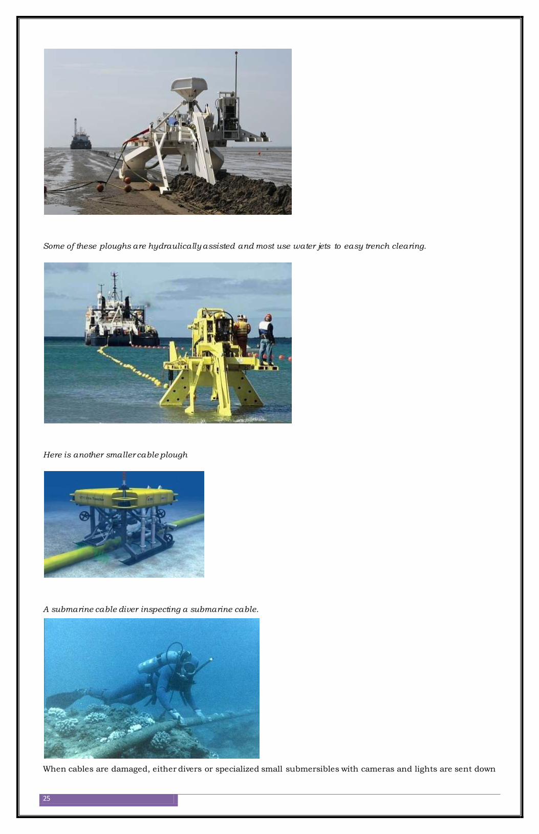
Here is the cable-plough on shore, being slowly pulled to the ocean
25
Some of these ploughs are hydraulically assisted and most use water jets to easy trench clearing.
Here is another smaller cable plough
A submarine cable diver inspecting a submarine cable.
When cables are damaged, either divers or specialized small submersibles with cameras and lights are sent down
26
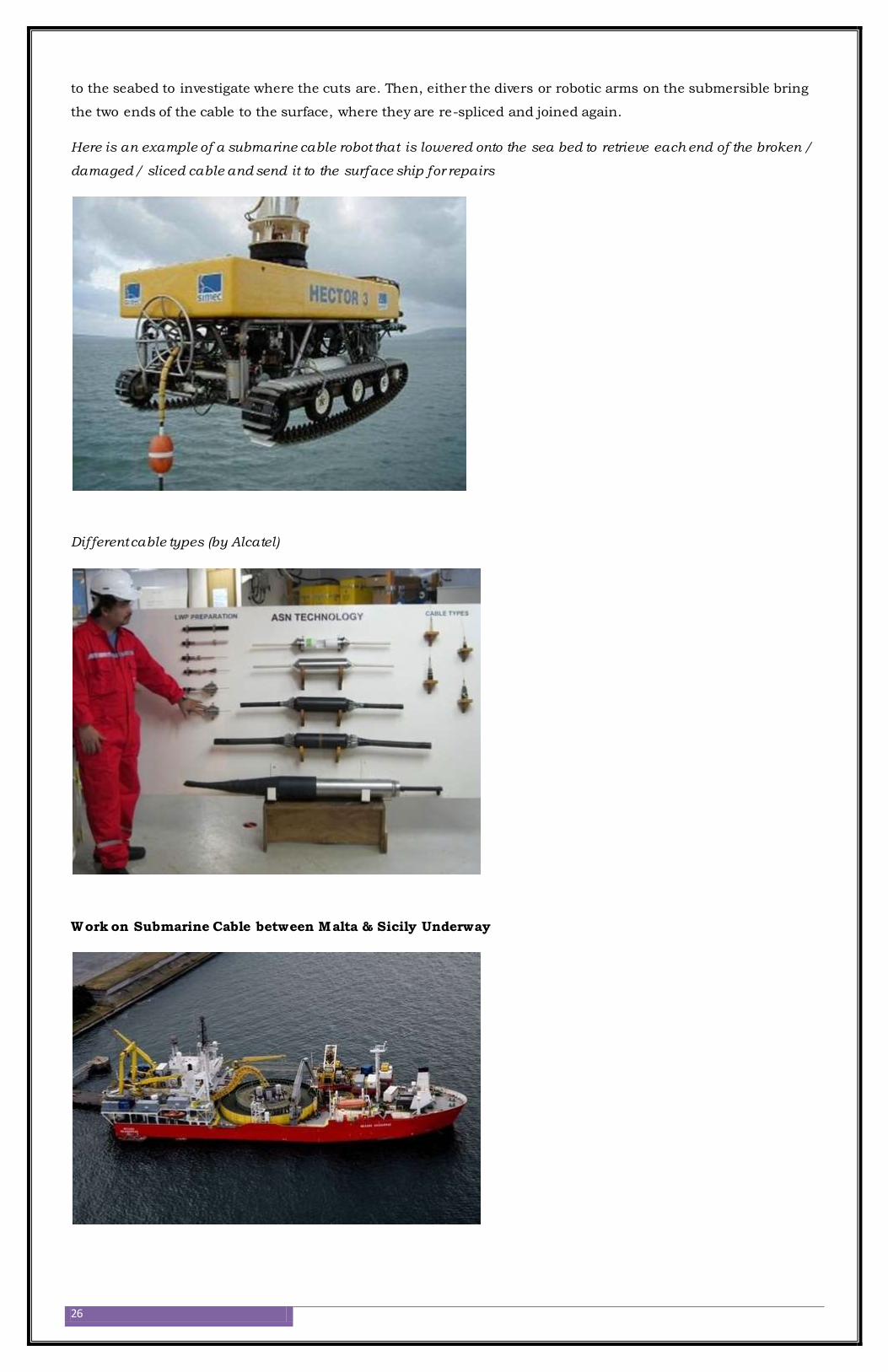
to the seabed to investigate where the cuts are. Then, either the divers or robotic arms on the submersible bring
the two ends of the cable to the surface, where they are re-spliced and joined again.
Here is an example of a submarine cable robot that is lowered onto the sea bed to retrieve each end of the broken /
damaged / sliced cable and send it to the surface ship for repairs
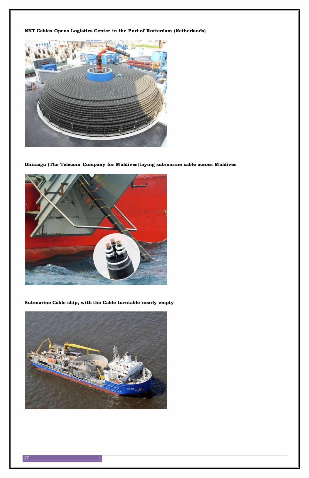
Different cable types (by Alcatel)
Work on Submarine Cable between Malta & Sicily Underway
27
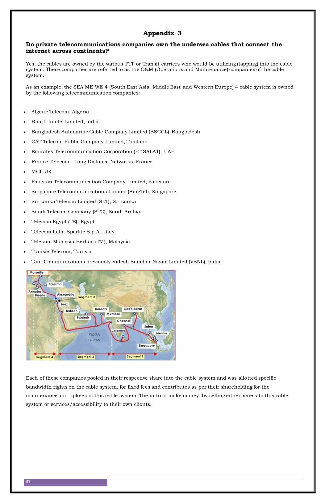
NKT Cables Opens Logistics Center in the Port of Rotterdam (Netherlands)
Dhiraagu (The Telecom Company for Maldives) laying submarine cable across Maldives
Submarine Cable ship, with the Cable turntable nearly empty

28
8. Bibliography
http://www.radio-electronics.com/info/telecommunications_networks/fiber-fibre-
optics/communications-basics-tutorial.php
http://computer.howstuffworks.com/fiber-optic.htm
http://www.cableorganizer.com/articles/fiber-optics-tutorial/history-production-fiber-
optic.html
http://www.allaboutcircuits.com/vol_4/chpt_14/5.html
http://www.gatewayforindia.com/technology/opticalfiber.htm
http://www.ias.ac.in/pramana/v57/p849/fulltext.pdf
http://www.extron.com/company/article.aspx?id=foddgga#4
http://www.ad-net.com.tw/index.php?id=472
http://www.quora.com/How-are-major-undersea-cables-laid-in-the-ocean
http://www.k-kcs.co.jp/english/s...).

29
9. APPENDIX – 1
Total Internal Reflection (TIR)
When light passes from a medium with one index of refraction (m1) to another medium with a lower index of
refraction (m2), it bends or refracts away from an imaginary line perpendicular to the surface (normal line). As
the angle of the beam through m1 becomes greater, (with respect to the normal line) the refracted light through
m2 bends further away from the normal line.
At one particular angle called critical angle (θ) the refracted light will not go into m2, but instead will travel
along the surface between the two media
NOTE: sine (θ) = n2/n1, where n1 and n2 are the indices of refraction [n1>n2].
If the beam through m1 is greater than the critical angle(θ), then the refracted beam will be reflected
entirely back into m1 (called TIR), even though m2 may be transparent!
In physics, the critical angle is described with respect to the normal line. In fiber optics, the critical angle is
described with respect to the parallel axis running down the middle of the fiber. Therefore, the fiber-optic critical
angle = 90º – θ.
In an optical fiber, the light travels through the core (m1, high index of refraction) by constantly reflecting from
the cladding (m2, lower index of refraction) because the angle of the light is always greater than the critical
angle(θ). Light reflects from the cladding no matter what angle the fiber itself gets bent at, even if it's a full circle!
Because the cladding does not absorb any light from the core, the light wave can travel great distances. However,
some of the light signal degrades within the fiber, mostly due to impurities in the glass. The extent that the
signal degrades depends upon the purity of the glass and the wavelength of the transmitted light (for example,
850 nm = 60 to 75 percent/km; 1,300 nm = 50 to 60 percent/km; 1,550 nm is greater than 50 percent/km).
Some premium optical fibers show much less signal degradation -- less than 10 percent/km at 1,550 nm.

30
APPENDIX – 2
Other Types of Fibers: Two additional types of fiber – very large core diameter silica fiber and fiber made
completely of plastic – are normally not employed for data transmission. Silica fiber is typically used in
applications involving high-power lasers and sensors, such as medical laser surgery. All-plastic fiber is useful for
very short data links within equipment because it may be used with relatively inexpensive LEDs. An isolation
system for use as part of a high voltage power supply would be a typical example of an application for plastic
fiber.
31
Appendix 3
Do private telecommunications companies own the undersea cables that connect the internet across continents? Yes, the cables are owned by the various PTT or Transit carriers who would be utilizing (tapping) into the cable system. These companies are referred to as the O&M (Operations and Maintenance) companies of the cable
system.
As an example, the SEA ME WE 4 (South East Asia, Middle East and Western Europe) 4 cable system is owned
by the following telecommunication companies:
Algérie Télécom, Algeria
Bharti Infotel Limited, India
Bangladesh Submarine Cable Company Limited (BSCCL), Bangladesh
CAT Telecom Public Company Limited, Thailand
Emirates Telecommunication Corporation (ETISALAT), UAE
France Telecom - Long Distance Networks, France
MCI, UK
Pakistan Telecommunication Company Limited, Pakistan
Singapore Telecommunications Limited (SingTel), Singapore
Sri Lanka Telecom Limited (SLT), Sri Lanka
Saudi Telecom Company (STC), Saudi Arabia
Telecom Egypt (TE), Egypt
Telecom Italia Sparkle S.p.A., Italy
Telekom Malaysia Berhad (TM), Malaysia
Tunisie Telecom, Tunisia
Tata Communications previously Videsh Sanchar Nigam Limited (VSNL), India
Each of these companies pooled in their respective share into the cable system and was allotted specific
bandwidth rights on the cable system, for fixed fees and contributes as per their shareholding for the
maintenance and upkeep of this cable system. The in turn make money, by selling either access to this cable
system or services/accessibility to their own clients.