Embed Size (px)
Citation preview

CX1000/CX2000CX defines the next generation in process control by fusing recording, control and networking into a single, compact product.CX delivers “Out of the box, ready to go” real-time and historical process monitoring.CX controls your process using internal PID loops and/or external controllers.CXs link your process to the networked world with a built-in 10 Base-T Ethernet and web server, E-mail and FTP functions.
Bulletin 04L31A01-01Ewww.yokogawa.com/ns/... and subscribe to “NetSOL Online”our free e-mail newsletter

32 32
TC
RTD
DCV
DI
Current
Voltage pulse
Relay
TCRTDDCV1-5V4-20mA
Measurementinput
Control input
Control output
Alarm and instaneousvalue notification by E-mail
Remote processmonitoring with Webbrowser
web browser
E-mail notification
E-mail notification
Easy setup of data acquisition/recording
SP math
PV
mat
h
PIDcomputation
Powerful and flexible control functions Independent/synchronous program control Embedded loop/PV math/SP math
Monitoring
Operation
Built-in monitor screen
Measurement ch
Embedded control
Program control(option)
CX1206 CX2620
6 ch 20 ch
2 loops 6 loopsControl interval: 250 msec
No. of patterns: 4 or 30No. of segments: Max. 99/pattern
Total number of segments: Max. 300
*A model with the program control option

54
Control modesUp to six control loops are available (CX2000). Three differentcontrol modes can be set: single loop mode, two-input switchingmode, and cascade mode.
Single-loopcontrol mode
LOOP1
SP
OUT
PV
Loop control withPV switching
LOOP1
SP
OUT
PV1
Cascade controlmode
LOOP2
OUT
PV2
PV1 LOOP1
SP
PV1
Flexible Control for a Variety of Applications
loop1 loop2 loop3 loop4 loop5 loop6
Multi loop control recording/monitoringbest suited to small systems
loop1 loop2
Compact control/measurementbest suited to install into device
CX2620: 6 embedded control loops, 20 measurement channels CX1206: 2 embedded control
loops, 6 measurement channels
PV Math/ SP Math can be applied for a variety of purposes.
PV math/ SP math can be used in PID computation. PID-computed result are used as PV or SP. By using the PV or SP that isevolved from original know-how, CX can control accurately in variety of applications.
Analog retransmissionData (measurement channel data, control loop data etc) is usedin Math expression. The math result is transmitted from CX con-trol output terminal
Note: As control output terminalis used as transmissionoutput, the loop is notavailable for PID control
Analog retransmission computation process
Analog output
SPPVch data(measurement,
Math ch etc)
Current output(0-20 mA, 4-20mA)Time propotional output(voltage pulse, relay)
CONTROLCONTROL
Easy to Switch Display Screens
Trend display screenMeasurement channels and control group PV,SP, OUT trends are displayed/recorded.
Control screenControl loop monitor screen. SP can bechanged.Display mode menu
MONITORINGMONITORINGStandard Quick-Start Monitoring ScreensScreens for Control Monitoring
Faceplate screenThis screen can be used for graphicalmonitoring of control loops.
Controller type display screenThis is a control loop monitoring screen. Thelarge digital display makes it easy to monitorPV.
Hybrid type display screenThis screen can be used for graphicalmonitoring of control loops.
Control overview screenAll control loops, measurement channels,external loops, and DIO status can bemonitored. It can be useful to monitor alarmstatus of all loops/channels and DIO status.
Tuning screenVarious control loop parameters can be set onthis screen. As many as 21 parameters canbe displayed and set.
DI/DO status displayThis screen can be used to monitor contact I/O ON/OFF statuses. It is useful for purposessuch as checking cables.
Program operation screenProgram pattern and measured value displayscan be displayed one on top of the other duringmeasurement.
DIO operation monitor screenDI/DO status is monitored and operated withcontrol loops, measurement channels, andexternal loops on the control screen.
Control operation summaryThis screen displays recordings of controloperations, such as control RUN/STOP, andswitching between AUTO and MAN.
PV math example for furnace applicationThe average of 3 measurementch is used as PV.PV=CLOG.AVE(01-03)
01-03CH
PVmath PID
OUT SCR
In combination with control, simple actions such as interlock, switch ON/OFFare available
DI
DI
control action(Run/Stop, Auto/Man)
LogicMath
Logic Math
PV Math/SP Math
SP mathPV
math
SP
Operands in equations
SP
PV
PV PID
OUT
PID
OUT
Embedded control dataExternal control dataMeasure ment channel dataMath channel dataDIO data, control input channel dataConstant*, internal switch* It can be set by user.It can be changed during operation
Operator types
"Four arithmetic operations, square root, absolute value, common logarithm, exponential, power, relational operations (>, ≥, <, ≤, ≠), logic operations (AND, OR, NOT, XOR), statistical operations (CLOG.AVE, CLOG.MAX, CLOG.MIN, CLOG.P-P), conditional operations ( [expression 1 ? expression 2 ? expression 3]"

76
Standard DI/DO for variety purposes· DI/DO expansion with DIO option (CX2000/CST1)Contact input (DI) function
DIDI 6 points control output
module for 1-2 loopDO 6 points
(Relay output 2 points, transistor output 4 points)
DIDI 6 points control output
module for 3-4 loopDO 6 points
(Relay output 2 points, transistor output 4 points)
DIDI 6 points control output
module for 5-6 loopDO 6 points
(Relay output 2 points, transistor output 4 points)
DIControl Purpose
extension DIO(option)
DO 12 points(Transistor output 12Points)
Action for recording/measurement
Record start/stop, trigger, alarm ACK, time set,math start/stop, math reset, manual samplesetting load, message, snap shot
Control action
All loops control operation start/stop, SP switching, auto operation, man operation, loop control with PV switching, control start/stop, remote/Local, cascade switching, pattern selection
Program operation action Program operation start/stop, hold/advance
Contact output (DO) function
*1: /A4F or /A4FR option must be specifiedNote: No DI/DO for 0 loop model
Measurement/control action
Measurement alarm, control alarm,FAIL*1, self-daignosis, memory end relay*1
Program operation action PV event, time event, pattern end
6points
6points
6points
12points
6points
6points
6points
12points
<TSP change during soak> <TSP change during ramp>
<Wait action in segment switching>
Program operation cannot move to the next segment until PV is in the wait zone. However, it will move to the next segment if wait time is past the setting time.
<Wait action within segment>
Program operation stops from time when PV is out of the wait zone to the time when it is in the wait zone.
Target setpoint (TSP) change: During program control TSP can be changed easily
HOLD
Program pattern after TSP change
TSP before change
HOLD release
segment 1 segment 2 segment 3 segment 4
PV
Program patternbefore TSP change
SP
segment 1 segment 2
upper limit
lower limit
wait zone
actual wait time
actual wait time
wait time(setting value)
SP
upper limit
lower limit
wait zone
HOLD HOLD release
segment 1 segment 2 segment 3 segment 4
Program pattern after TSP change
PV
TSP beforechange
Program patternbefore TSP change
During program operation, the operation can be held and the segment TSP can be changed. Also, pattern change is available during program control.
Wait function: Flexible response to process change
PV
PV
Synchronous or independent program operation up to 6 embedded loopsAs program operation is available for each loop, the CX can be applied for a variety of applications. Up to 30 program patterns can be set.
Functional Program Operation
Independent multi-program pattern operationUp to 6 program patterns can be controlled independentlyExample: Independent program operation for 6 furnaces using the CX2620
furnace1 furnace6furnace2 furnace3 furnace4 furnace5
Pattern1 Pattern6Pattern2 Pattern3 Pattern4 Pattern5
Synchronous multi-program pattern operationUp to 6 program pattens can be controlled in the same time period
Example: Synchronous program operation for a furnace using the CX2620
Zone1
Zone2
Zone3
Zone4
Zone5
Zone6
Simultaneous use of program operation and fixed-point contol mode
Example: Synchronous program operation for 3 loops, fixed-point control mode on one loop using the CX2420
Zone1
Zone2
Zone3
loop1
fixed-pointcontrol mode
PROGRAM CONTROLPROGRAM CONTROL
Distinguished display of program pattern processPresent program pattern proceeding point
Program pattern
Past PV trend
Program pattern and PV can be displayed one on top of the other during program control
All time events display for a pattern
(Group display) (All display)
Display of event name registered as group
PV eventsdisplay by
present point
Program pattern and program events can be displyed simultaneously
Time events and PV events can be set at any position in the pattern.16 time events and 16 PV events can be dis-played in program con-trol display (all display).Any 5 selected events can be displayed (group display).
•
•
•
(*) Program control is an option (specity /PG1 or /PG2)

98
Memory CapacityCX1000/CX2000: Saving data to internal memory
Model
CX2220CX2620
4 s12.8 hours8.7 hours
2 s6.4 hours4.3 hours
10 s1.3 days
21.9 hours
1 min.8 days
5.4 hours
2 min.1 min. 5 min. 30 min.
MaximumSaving time
Saving interval
Display update interval
(Approximately)
Model
CX2220CX2620
4 s25.6 hours17.5 hours
2 s12.8 hours8.7 hours
10 s2.6 days1.8 days
1 min.16 days
10.9 days
Saving interval
MaximumSaving time
(Approximately)
Model
CX1006CX1206
4 s2.3 days1.1 day
2 s1.1 day
13 hours
10 s5.7 days2.8 days
1 min.34.7 days17 days
2 min.1 min. 5 min. 30 min.Saving interval
Display update interval
MaximumSaving time
(Approximately)
Model
CX1006CX1206
4 s4.6 days2.3 days
2 s2.3 days1.1 days
10 s11.5 days5.7 days
1 min.69.4 days34.7 days
Saving interval
MaximumSaving time
(Approximately)
CX2000 displaydata file
CX1000 event data file
CX2000 eventdata file
CX1000 displaydata file
Protecting Data during a Power InterruptionCX series instruments use flash memoryas internal memory for storing measure-ment data. Flash memory is a type ofnonvolatile memory that does not requirea battery backup. Power interruptions willnot cause it to lose stored data.
Measurement datarecording
Control data recording
PV,SP,OUT
MANUAL modeIn MANUAL mode, the data held in internal memory isstored on removable storage media when you insert themedia in the drive. This mode is useful in cases whereyou want to store a relatively small amount of data on afloppy disk for quick checking.
AUTO modeIn AUTO mode, data is stored at preset intervals on theremovable storage media inserted in the media drive. Thisrecording mode is ideal for saving measurements overextended periods of time in automated recording systems.
Settings FileLike measurement data, settings data canbe saved as a separate file on external stor-age media.
Memory FunctionDAQSTATION provides a variety of recording options that go far beyond the capabilities of conventional recorders. These features letyou efficiently record just the data you need, saved to your choice of removable PC storage media.Optional Compact flash memory card or Zip disks allow data recording over extended periods of time in automated recordingsystems.
Other dataIn addition to measurement data, the CX1000/CX2000 can also save the following types of data:• Manual sampling data: Instantaneous values (the 50 most recent measurements) occurring at each contact input or key input are
saved in ASCII format.• Time-series (TLOG) calculation data: Maximum value, minimum value, integrated (totalized) value, etc. during a fixed interval (with
the calculation option)• Report data: Hourly reports, daily reports, weekly reports, monthly reports (with the calculation option)• Settings data: Settings for set mode and setup mode• Alarm summary data: Information on the occurrence/cancellation of alarms on channels being recorded• Occurrence/cancellation of time/PV event• Control mode summary data: Run/stop, local/remote and manual/auto/cascade mode switching, hold/cancellation of programs
hold, wait/cancellation of wait
Versatile and Flexible Recording Functions to Increase DataAcqusition Efficiency in the Field
DisplayMeasurement input
Control input
4-20 mA current output
Voltage pulse
C contact relay
Externalmemory media
TC
RTD
DCV
DI
TC
RTD
DCV
1-5V
4-20mA
Control output
MEASURMENT & MEMORYMEASURMENT & MEMORY
Measurement dataDisplay data—for extended-period trend recordingThe display data format is used to save data displayed as wave-forms. Each time the waveform display is updated, two data val-ues (maximum and minimum values) measured since the previ-ous update are saved.
Enlargement
Maximum value
Minimum value
1 minute (1 dot)
Conceptual illustration of displayed data file (with waveform refresh rate of 30 min/div)
These two data values are saved every minute.
1 div 30 minutes (30 dots)
Data saved from pretrigger functions
Saved data
Trigger detection
Measurementdata
Event data—for detailed analysisThe event data format is used to save all data in a specified datasaving interval. Event data can be used in combination with thetrigger functions to detect and analyze abnormal data.A pretrigger can also be set, making it possible to analyze databefore and after the trigger.
File structureThe two data formats can be used in combinations such as the following:q Display data onlyw Event data onlye Display data and event data in combination
Display data, event data, and a trigger function can be used in combi-nation. With this approach, display data with a slow sample rate can beused for continuous extended-period recording, and event data with afaster sample rate can be used to record short-term details.
Display data
Trigger occurs Trigger occurs
Waiting for trigger
Waiting for trigger
Measured phenomenon
Event Event
Control PV, SP, OUT can be recorded/displayed
Note: No computation channel and no external channel.

1110
LAN
In this type of setup, e-mail messages are sent through an existing mail server (SMTP server).
CX1000 CX2000
InternetLAN
The CX can also send e-mail through a PSTN line or cellularphone using an Internet Service Provider (ISP).
Mail server(SMTP server)
LANMail reception
Internete-mail-capablecellular phone
Mail reception
Mail reception
Cellular phone
Adapter
Dial-up routerand modem
PSTN line orleased line Internet
ServiceProvider
(ISP)Internet
E-mail functionThe CX can transmit the following data via e-mail: alarm notification messages, power-restoration messages following an outage,memory full messages, storage media full messages, periodic instantaneous values, report data, and other information. Multiplerecipients can be registered.When connected to the Internet, CX can send e-mail anywhere in the world. An e-mail-capable cellular phone can be used to receiveinstantaneous remote notification of alarms.
Internet e-mail-capablecellular phone
Mail reception
Mail receptionCX1000 CX2000
Sending e-mail using an existing mail system
Sending e-mail from a remote site with no existing mail system
FTP function
FTP client function FTP server function
The FTP client function makes it possible to make periodic, auto-matic transfers to a file server of data saved in the CX1000/CX2000 internal memory. A maximum of two servers (primaryand secondary) are supported, so files are automatically trans-ferred to the secondary server if the primary server fails.
The FTP server allows a client computer to download all filesstored on the CX1000/CX2000 storage medium.
FTP client
Service request
Ethernet
FTP server
FTP client
Ethernet
Primary SecondaryFTP servers
Automaticallytransferable files
Display data filesEvent data filesReport files
Internet mail-capablecelluler phone
Analog line, ISDN line,leased line, packetnetwork
Internet browser
Internet browser
DAQEXPLORERDAQLOGGER
client
Internet
LAN(Intranet segment)
OPC server
FTP server
Ethernet
Ethernet
Dial-up routerwith internal
modemAnalog line,ISDN line,leased line
Dial-uprouter
Remote monitoring
E-mail notifications
E-mailnotificationsAlarm data, instantaneous values at preset times, report reception
E-mail notificationsAlarm data,instantaneous values atpreset times, report reception
Field Contents on the Web
Control and Measurement Data Acquisition/Monitoring via Internet
OPEN/NETWORKOPEN/NETWORK
Web monitoringCX screen data can be displayed on a web browser. The user can also change the CX screen display type (trend display, digitaldisplay, bar graph display, historical trend display, etc.) and display groups, and enter messages through the browser. The CX Webserver function makes it easy to set up a remote monitoring environment with little or no startup costs.
Message input functionMessages can be input to the CXscreen from a browser screen Trend display
Messages can beinput remotely
Alarm information displayDisplays the most recent 120 events
Control channels displayDisplays instaneous values andalarm statuses for all channels
Measurement mathchannels displayDisplay instaneos value andalarm statuses for all channels
Displaying the CX screen ona web browser
Example addresshttp://192.168.0.10/operator.htm
The screen display type and displaygroups can be changed here

1312
DAQEXPLORER (Compatible with Windows98/Me/NT4.0/2000/XP)DAQEXPLORER is a software package that supplements the DAQSTANDARD features with functions such as
Desktop and Data Monitor. DAQEXPLORER lets you take full advantage of network functions through the CXs'
Ethernet connection.
Measurement Data File TransferDAQEXPLORER makes it possibble to transfer measurementdata files from a CX to a PC
Measured Data Monitoring• Data Monitor module monitors CX measurements over the
network.• An optional auto-file-conversion function improves the efficiency
of data processing tasks through automatic conversion of datafiles.
DAQEXPLORER DAQEXPLORER
Connect up to sixteen units, including DX units and other DAQEXPLORER data monitors
DX100
DX200 CX2000
Ethernet
You can monitor measurements from DX units mounted on DAQEXPLORER desktops running on other PCs.
DAQLOGGER (Compatible with Windows 98/NT4.0/2000/XP)Multi-Channel Real-Time Data Logging Software
DAQLOGGER integrates up to 1600 data acquisition channels from as many as 32 recorders connected in a multi-drop configurationthrough Ethernet and serial links (RS-232-C/RS-422-A). The configuration may include a mixture of DAQSTATION CX/DX seriesunits, MobileCorder MV series units, µR and VR recorders, and DARWIN data acquisition units.DAQLOGGER also supports internet applications. It lets you send e-mail messages (which can include binary file attachments) andtransfer binary files (FTP client) to specified addresses at a set time or when an event occurs such as an alarm or when a file iscreated. Remote site monitoring is avalibable via PC.
DAQLOGGER Client
DAQLOGGER
• Real-time remote monitoring • Redisplay of acquired data
• Simultaneous access by up to 16 clients
Ethernet
Client Client Client Client
PC server
RS-422-A
µRCX2000 DX200
RS-232-C
DX200
Ethernet
CX2000 DX200DARWIN
RS-232-C/RS-422-A converters
• Can acquire and monitor real-time data on up to 1600 data acquisition channels from as many as 32 recorders connected in a multi-drop configuration.
• Works with a mixture of RS-422-A, RS-232-C, and Ethernet links.
• Fully supports settings in DAQSTATION, MobileCorder, DARWIN, µR and VR recorders.
• Sophisticated monitoring functions.
• Data transmission to client PCs.
Application Software
The application software options that let you open and work with data recorded on CX series instruments and
easily use CX network functions are an integral part of DAQSTATION recorders. They will help you integrate your
CX series instruments with your PCs and network.
DAQSTANDARD (Standard Software Compatible with Windows 98/Me/NT4.0/2000/XP)DAQSTANDARD is a software package included with all CX series instruments. It can be used to print or redisplay datafiles saved by the CX unit or transferred through FTP.• Setup Module
The Setup module is used to send the CX data such as settings relating to measurement channels, calculation channels, or the screendisplay. It can also receive settings from the CX and save them to a PC hard disk or other storage device.
• Data Viewer
The Data Viewer module can be used to display and printdata in files generated by the CX. Data can be displayed astrend displays, digital displays, circular displays, and lists. Inaddition, the cursor can be used to read numerical values indisplayed data, or to make interval calculations. Data can beconverted to ASCII, or to file formats that can be opened inExcel or Lotus 1-2-3.
• Linked File Display
Data files generated by breaking up contiguous data intomultiple files as a result of auto-saving or a power interrup-tion during continuous data acquisition by the CX unit canbe displayed as linked files. You can save the file linking con-ditions, so it is easy to redisplay linked files. Using the linkedfile display, you can also convert data to ASCII or file for-mats that can be opened with Excel and Lotus 1-2-3.
• Program Pattern Setting
DAQSTATION CX embedded control loop program opera-tion patterns can be created and set through a graphical in-terface.
Measurement channel settings Display settings
Data Viewer
Program pattern settings
SOFTWARESOFTWARE

1514
PLC Communication
The PLC has the ability to read the CX's control/measurement data and to send commands to the CX from PLC
Data read
Control/measurement data
Data write
Ladder Program ExampleCommunication register dataMemory stop/startAlarm ACKMath start/stop/resetAlarm value settingProgram operation stop/hold, pattern switchingControl operation start/stopParameter kinds for each loopPID parameters for each loopTarget setpoint (SP) number
DAQSTATION supports the Modbus protocol (RTU master/slave), for easy installation on systems built using Modbus.
Modbus Master FunctionThe Modbus master function lets the CX unit read, display, andrecord digital data from slave devices.
• Increase CX InputsA Modbus connection lets you input measurements and cal-culations from a DARWIN series* data acquisition unit asdigital data to CX unit computation channels. This capabilitymakes it possible to increase the number of CX unit inputsby simultaneously using DARWIN series measurement/com-putation channels.
* Communication module DT300-31/S6 is required. See the general specifica-tions for DT300-31/S6 for further details.
• Data Display/Record of Indicating Controller/Power Monitor
Data from Modbus-compatible devices can be input to CXunit computation channels as digital data for displaying andrecording. For example, the CX unit can produce trend dis-plays and save data such as power monitor cumulative power,indicator regulator SP, PV, and OUT.
In addition, data from these devices can be used by CX unitnetwork functions and network applications.
For information on the operating requirements of individual Modbus slave devices,see the specifications for the particular slave device.
Modbus Slave FunctionA master device can read CX unit register values. In addition, data written to the register by the host system can be displayed andrecorded on the CX unit.
Modbus Communications
FTP serverDAQOPCE-mailInternet browserDAQLOGGERDAQEXPLORER
Ethernet
RS-422 Modbus
Communication digital input DARWIN
DA100 (standalone/expandable model) DC100 (standalone/expandable model) DR232 (expandable model) DR242 (expandable model)
Analog input4-20 mA, thermocouple, RTD, voltage, etc.
Analog input4-20 mA, thermocouple, RTD, voltage, current, distortion, pulses, etc.
FTP serverDAQOPCE-mailInternet browserDAQLOGGERDAQEXPLORER
Ethernet
RS-422 Modbus
Communication digital input
Power monitor UZ Series
Indicating controller
UT/UP Series
PV, SP, OUT, etc.
Cumulative power, arbitrary cumulative power, instantaneous cumulative power, etc.
Analog input4-20 mA, thermocouple, RTD, voltage, etc.
* Two-loop controllers count as two loops each.
Using DAQSTATION CX as a Control TerminalDAQSTATION CX lets you control, monitor, and collect data fromcontrollers in various locations. The screens needed for control-ler operation and monitoring are included as standard features.The user-friendly display function lets you set operation param-eters for Green series units.
Using DAQSTATION CX as a Data CollectorDAQSTATION CX can record controller measurements, settings,and control outputs. Control statuses and operation statuses areeasy to record. In addition, it is easy to collect data for qualitycontrol and creating reports.
Fewer CablesMeasurements from Green series units are transmitted to aDAQSTATION CX through an RS-485 interface. As all Greenseries units do not have to wire to CX, it can eliminate the needfor individual twisted pair input wiring from controller to CX.
Network-Based MonitoringDAQSTATION CX can be set to transmit an E-mail when a con-troller outputs an alarm. This lets you monitor for alarms even ifyou are not on site. In addition, the DAQSTATION CX screencan be displayed on any PC Web browser.
CX1000 CX2000
4 16Maximum number ofconnected loops*
UT320, UT350, UT351, UT420, UT450, UT520, UT550, UT750(MODBUS protocol support required)Connectable models
DAQSTATION CX's monitoring and recording functions are not limited to embedded control loops. A DAQSTATION CX lets youcontrol external Green series controllers with the same ease as DAQSTATION CX's embedded controls. This expands DAQSTATIONCX's scope and provides a broader range of applications.
COMMUNICATIONCOMMUNICATIONGreen Series Communication

16 17
SPECIFICATION
Standard Specifications Construction
Angle of mounting: Backward tilt of up to 30°; no tilt is allowed on either side, however.Thickness of mounting panel: 2 to 26 mmMaterial: Case = Steel plate, Bezel = PolycarbonateColor of coating: Case = Pale cobalt blue (equivalent to DIC 16 edition 102)
Bezel = Light charcoal gray (equivalent to Munsell 10B3.6/0.3)Front panel: Dust- and drip-proof (compliant to IEC529-IP65, NEMA No. 250 Type 4 [except for
icing tests]) CONTROL FUNCTIONS
Control mode: Select from three control modes, i.e., single loop, cascade control, and loop controlwith PV switching.Note) The control mode is fixed to single loop control for loops 5 and 6.
Control computation functions:Continuous PID control, relay on/off control, time proportional PID control
Setting Ranges of Control ParametersProportional band: 0.1 to 999.9%Integral time: 0 to 6000 secDerivative time: 0 to 6000 secOn-off control hysteresis wideth: 0.0 to 100.0% of measurement rangePreset output value: -5.0 to 105.0% of output
(Provided in case of control computation being stopped, PV input being in aburnout state, or instrument input being abnormal)
Output limiter: Setting range: -5.0 to 105.0% for both high/low limitsShutdown function: Can provide a manipulated output of up to 0 mA when in manual mode operation with
4–20 mA output (shuts down the output for values smaller than -5.1%).Output rate-of-change limiter: Off, or a value from 0.1 to 100.0%/sec
ALARM FUNCTIONS Control Alarm
Types of control alarm: PV high limit, PV low limit, high limit of deviation, low limit of deviation, deviation withinhigh and low limits, SP high limit, SP low limit, OUT high limit, and OUT low limit
Other alarm type: Fault diagnosis, fail outputStand-by action: Turns off PV/SP alarm from starting control until steady conditionAlarm output: 6 points/ 2 loops (transistor output 4 points, relay output 2 points)Alarm setting: 4 types/ loopHysteresis: Can set each alarm settingDisplay: The status is shown in the digital display in case of alarm. A common alarm
indication is also displayed. The alarm behavior: non-hold or hold-type can beselectable for common to all channels
Measurement AlarmTypes of alarm: High limit, low limit, differential high limit, differential low limit, high limit of rate-of-
change, low limits of rate-of-change, high limit of delay, and low limits of delay(alarm delay)
Alarm delay time: 1 to 3600 sec (1 hr)Time interval of rate-of-change alarm: Measuring interval × 1 to 15Alarm output: 6 points (option) *alarm output can be assigned to control outputNumber of setting: Max. 4/ each channelHysteresis: ON (0.5% of span)/ OFF selectable (common to all channels and all levels)Display: The status is shown in the digital display in case of alarm. A common alarm
indication is also displayed. The alarm behavior: non-hold or hold-type can beselectable or common to all channels
INPUT SECTION Specifications Common to Control and Measurement Inputs
Thermocouple burnout:Switchable between ON/OFF options of detection on a channel basis.Switchable between burnout upscale/downscale options
Integral time of Select from the options of 20 ms (50 Hz), 16.7 ms (60 Hz) and AUTO A/D converter: (automatic switching between 20 ms and 16.7 ms depending on the power supply frequency).
Control InputInput interval: 250, 500 or 1000 ms, synchronized with the control periodInput type: DC voltage (DCV), thermocouple (TC), resistance temperature detector (RTD),
DC current (DCA) with external shunt resistor
General Specifications
Control intervalControlled pointsMeasurement intervalMeasurement channels Universal output
DIDO
EthernetRS422A/485RS232
Program setting function Measurement alarm
Mathmatical function DIO expanded module
VGA output3-wire isolated RTD input24 V DC/AC power supply24 V DC transmitter power outputBatch header
Display Control modesControl calculation functionsPID control (embedded)Monitoring
Control I/O specifications
Program patterns: 4 max (/PG1) or 30 max (/PG2)Segments: Max 99 per pattern, Total segments: 300 max
CX1000 CX20005.5-inch TFT color LCD 10.4-inch TFT color LCD
0, 2 0, 2, 4, 6
6 channels 10 channels, 20 channels
Single loop control, cascade control, two-input switching control
250, 500, 1000 ms
1 second, 2 seconds
Standard feature
Optional (one only)
Floppy disks, ZIP disks, CompactFlash memory card
Continuous PID control, relay ON/OFF control, time-proportionatePID control, overshoot control function (Super)
Select from the following: 4-20 mA current output / Voltage pulse /Transfer contact relay.Contact input: 6 points/2 loopsOpen collector transistor output: 4 points/2 loopsMake contact relay output: 2 points/2 loops
External storage media
12 channels –
–Can be specified Can be specified
–Can be specified
30 channels Contact inputs: 12
Open collector outputs: 12Can be specifiedCan be specifiedCan be specifiedCan be specifiedCan be specified
Communicationinterface
Optional functions
/A4F: 4 alarms, with fail output/A4FR: 4 alarms, with fail output and remote
/A6: 6 alarms only/A6R: 6 alarms, with remote
Linear scaling: Input ranges capable of scaling:Thermocouple (TC), resistance temperature detector (RTD), and DC voltage (DCV)
Available range of scaling:-30000 to 30000, with a span smaller than 30000Computation of input/output signalMeasurement input computation:
Input processing, square root extraction (0.0 to 5.0% low level cutoff), 10-segmentlinealizer, and 10-segment linearizer biasing, and bias addition (from -100.0 to100.0% of measuring range), first order lag filter (time constant = 1 to 120 sec, or off)
Auxiliary computation input:Input processing, square root extraction (0.0 to 5.0% low level cutoff), bias addition(from -100.0 to 100.0% of measuring range), ratio multiplication (0.001 to 9.999),and first order lag filter (time constant = 1 to 120 sec, or off)
Table of Control Input Specifications
Input type Range20 mV60 mV200 mV2 V6 V20 V50 VR*1
S*1
B*1
K*1
E*1
J*1
T*1
N*1
W*2
L*3
U*3
PLATINELPR40-20W3Re/W25RePt100*4
JPt100*4
1 to 5 V
DCV– applicable to linear scaling only
TC
RTD*5
Standardized signal
*1: R, S, B, K, E, J, T, N : IEC584-1 (1995), DIN IEC584, JIS C1602-1995*2: W : W-5% Re/W-26% Re (Hoskins Mfg. Co.), ASTM E988*3: L : Fe-CuNi, DIN43710, U : Cu-CuNi – DIN43710*4: Pt100 : JIS C1604-1997, IEC751-1995, DIN IEC751-1996 JPt100 : JIS C1604-1989, JIS C1606-1989*5: Measuring current : i = 1 mA
Measuring range–20.00 to 20.00 mV–60.00 to 60.00 mV–200.0 to 200.0 mV–2.000 to 2.000 V–6.000 to 6.000 V–20.00 to 20.00 V–50.00 to 50.00 V0.0 to 1760°C0.0 to 1760°C0.0 to 1820°C–200.0 to 1370°C–200.0 to 800°C–200.0 to 1100°C–200.0 to 400°C0.0 to 1300°C0.0 to 2315°C–200.0 to 900°C–200.0 to 400°C0.0 to 1400.0°C0.0 to 1900.0°C0.0 to 2400.0°C–200.0 to 600.0°C–200.0 to 550.0°C1.000 to 5.000 V
Measurement InputMeasuring interval: 1 or 2 sec (2 sec, if the integral time of A/D converter is 100 ms)Input type: DC voltage (DCV), thermocouple (TC), resistance temperature detector (RTD),
Operation log (DI), DC current (DCA) with external shunt resistorMeasurement Input Ranges and Measuring Ranges
Input type Input Range20 mV60 mV200 mV2 V6 V20 V50 VR*1
S*1
B*1
K*1
E*1
J*1
T*1
N*1
W*1
L*3
U*3
PLATINELPR40-20W3Re/W25RePt100*4
JPt100*4
DCV input
Contact input
DCV
TC
RTD*5
DI
Measuring Range–20.00 to 20.00 mV–60.00 to 60.00 mV–200.0 to 200.0 mV–2.000 to 2.000 V–6.000 to 6.000 V–20.00 to 20.00 V–50.00 to 50.00 V0.0 to 1760.0°C0.0 to 1760.0°C0.0 to 1820.0°C–200.0 to 1370.0°C–200.0 to 800.0°C–200.0 to 1100.0°C–200.0 to 400.0°C0.0 to 1300.0°C0.0 to 2315.0°C–200.0 to 900.0°C–200.0 to 400.0°C0.0 to 1400.0°C0.0 to 1900.0°C0.0 to 2400.0°C–200.0 to 600.0°C–200.0 to 550.0°COFF: lower than 2.4 VON: 2.4 V or higherON/OFF states
*1: R, S, B, K, E, J, T, N : IEC584-1 (1995), DIN IEC584, JIS C1602-1995*2: W : W-5% Re/W-26% Re (Hoskins Mfg. Co.), ASTM E988*3: L : Fe-CuNi, DIN43710, U : Cu-CuNi – DIN43710*4: Pt100 : JIS C1604-1997, IEC751-1995, DIN IEC751-1996
JPt100 : JIS C1604-1989, JIS C1606-1989*5: Measuring current : i = 1 mA
Filter function: Switchable between ON/OFF options of moving average on a channel basis;
selectable from 2 to 16 times for the frequency of moving average calculation
ComputationDifference computation: Allows for calculation of difference between any two channels.
Input ranges capable of difference computation: DCV, TC and RTD
Linear scaling: Input ranges capable of scaling: DCV, TC, RTD
Available range of scaling:-30000 to 30000
Square root scaling: Input ranges capable of scaling: DCV
Available range of scaling:-30000 to 30000
Storage Functions:Store internal control loops’ data (PV, SP and OUT of internal loops), Green series communication
loops’ data (PV, SP and OUT of connected Green series communication), measured data, and
computed data.
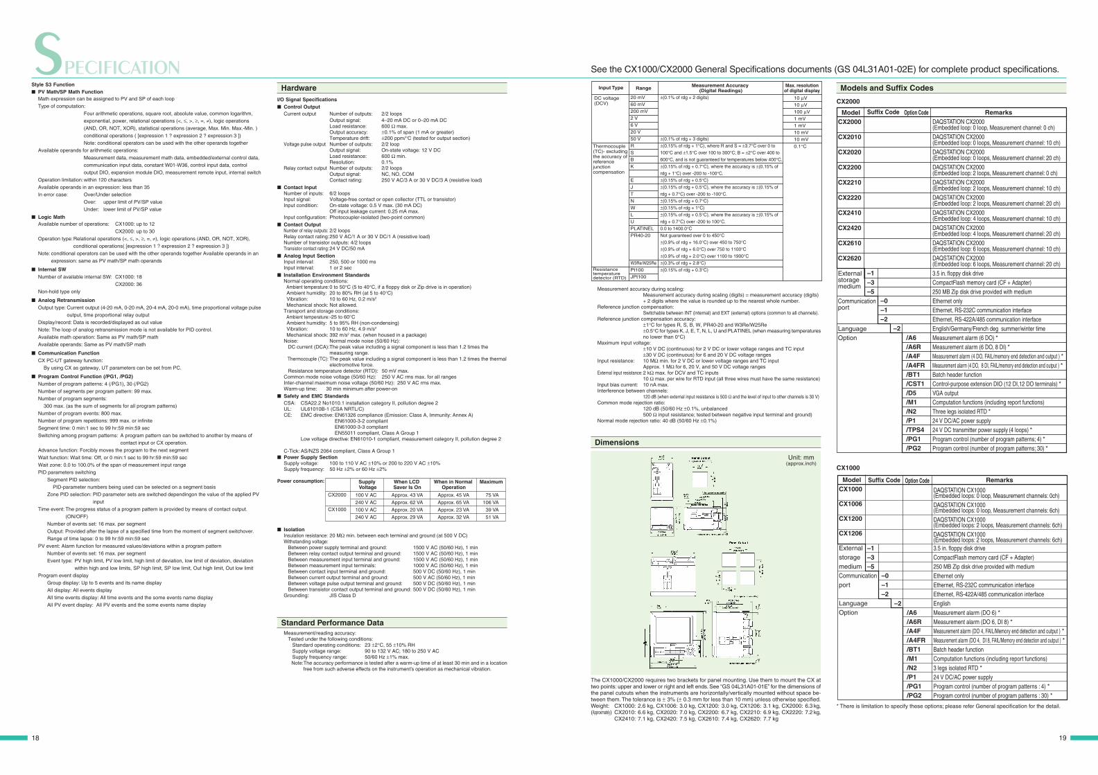
See the CX1000/CX2000 General Specifications documents(GS 04L31A01-02E) for complete product specifications.
Output relays
HARDWAREHARDWARE
In the half-century since introducing the ER electron-tube automatic balancing recorder (Japan’s first) in 1951,YOKOGAWA has shipped more than one million industrial recorders to users around the world. The DX SeriesDAQSTATION incorporates the highly reliable technology that YOKOGAWA has developed through its manyyears of expertise as a recorder manufacturer.
Dust-Proof and Water-Proof Front Panel (IP65, NEMA No.250 TYPE4* Compliant)YOKOGAWA designed CX series instruments to be used under harsh environmental conditions.The front panel has a dust-proof, water-proof design which is compliant with the IEC529-IP65 and NEMA No. 250 TYPE4* standard. This structure provides good protection for therecorder’s internal components and the removable storage media drive mechanism.Compliance with IP65 means that the front panel has met stringent requirements such ascomplete protection (of internal components) against dust, and protection against functionalerrors even when the recorder is sprayed with a jet stream. The ability of CX series instrumentsto endure such environmental conditions has been proven through stringent evaluation tests.*Except external icing test.
Quality Components• High-Breakdown-Voltage Solid-State Relays
CX series instruments use high-breakdown-voltage solid-state relays developed byYOKOGAWA as scanners for switching input signals. These relays consist of MOSFETscapable of withstanding high voltage (1500 V DC) with low leakage current (3 nA), and power-output photocouplers. They provide high-speed scanning while increasing scanner life andeliminating noise.
• Isolated Channel Inputs
DC voltage and thermocouple inputs in all CX series models are channel-isolated. (Channelisolation for RTD inputs is optional on some models.) The high common mode noise characteristic enabled by isolated channelinputs ensures stable measurements in a wide range of fields.
• M4 Screw Input Terminals
Input terminals are the “entryways” through which allmeasurements enter a recorder. Their reliability is critical tostable data collection. Rugged M4 screw input terminals areused in all CX series recorders.
• Compliance with Safety Standards and EMC Standards
Another indication of the reliability of CX series instruments istheir compliance with the stringent specifications of theinternational safety and electromagnetic compatibility (EMC)standards. Of course, CX series instruments have also met CEstandards.
• Replacing Output Relays
Control output relays wear out over time, so the DAQSTATIONCX is designed to make it easy to remove and attach the relaysfrom the output module. This makes maintenance work and fieldreplacements easier.
Reliable Hardware
1918
The CX1000/CX2000 requires two brackets for panel mounting. Use them to mount the CX attwo points: upper and lower or right and left ends. See “GS 04L31A01-01E” for the dimensions ofthe panel cutouts when the instruments are horizontally/vertically mounted without space be-tween them. The tolerance is ± 3% (± 0.3 mm for less than 10 mm) unless otherwise specified.Weight: CX1000: 2.6 kg, CX1006: 3.0 kg, CX1200: 3.0 kg, CX1206: 3.1 kg, CX2000: 6.3 kg,(Approximately) CX2010: 6.6 kg, CX2020: 7.0 kg, CX2200: 6.7 kg, CX2210: 6.9 kg, CX2220: 7.2 kg,
CX2410: 7.1 kg, CX2420: 7.5 kg, CX2610: 7.4 kg, CX2620: 7.7 kg
SPECIFICATIONInput Type
DC voltage (DCV)
Thermocouple (TC)- excluding the accuracy of reference junction compensation
Resistance temperature detector (RTD)
10 µV
10 µV
100 µV
1 mV
1 mV
10 mV
10 mV
0.1°C
20 mV
60 mV
200 mV
2 V
6 V
20 V
50 V
R
S
B
K
E
J
T
N
W
L
U
PLATINEL
PR40-20
W3Re/W25Re
Pt100
JPt100
±(0.1% of rdg + 2 digits)
±(0.1% of rdg + 3 digits)
±(0.15% of rdg + 1°C), where R and S = ±3.7°C over 0 to
100°C and ±1.5°C over 100 to 300°C; B = ±2°C over 400 to
600°C, and is not guaranteed for temperatures below 400°C.
±(0.15% of rdg + 0.7°C), where the accuracy is ±(0.15% of
rdg + 1°C) over -200 to -100°C.
±(0.15% of rdg + 0.5°C)
±(0.15% of rdg + 0.5°C), where the accuracy is ±(0.15% of
rdg + 0.7°C) over -200 to -100°C.
±(0.15% of rdg + 0.7°C)
±(0.15% of rdg + 1°C)
±(0.15% of rdg + 0.5°C), where the accuracy is ±(0.15% of
rdg + 0.7°C) over -200 to 100°C.
0.0 to 1400.0°CNot guaranteed over 0 to 450°C±(0.9% of rdg + 16.0°C) over 450 to 750°C±(0.9% of rdg + 6.0°C) over 750 to 1100°C±(0.9% of rdg + 2.0°C) over 1100 to 1900°C±(0.3% of rdg + 2.8°C)
±(0.15% of rdg + 0.3°C)
Range Max. resolutionof digital display
Measurement Accuracy (Digital Readings)
Measurement accuracy during scaling:Measurement accuracy during scaling (digits) = measurement accuracy (digits)+ 2 digits where the value is rounded up to the nearest whole number.
Reference junction compensation:Switchable between INT (internal) and EXT (external) options (common to all channels).
Reference junction compensation accuracy:±1°C for types R, S, B, W, PR40-20 and W3Re/W25Re±0.5°C for types K, J, E, T, N, L, U and PLATINEL (when measuring temperaturesno lower than 0°C)
Maximum input voltage:±10 V DC (continuous) for 2 V DC or lower voltage ranges and TC input±30 V DC (continuous) for 6 and 20 V DC voltage ranges
Input resistance: 10 MΩ min. for 2 V DC or lower voltage ranges and TC inputApprox. 1 MΩ for 6, 20 V, and 50 V DC voltage ranges
External input resistance: 2 kΩ max. for DCV and TC inputs10 Ω max. per wire for RTD input (all three wires must have the same resistance)
Input bias current: 10 nA max.Interference between channels:
120 dB (when external input resistance is 500 Ω and the level of input to other channels is 30 V)Common mode rejection ratio:
120 dB (50/60 Hz ±0.1%, unbalanced500 Ω input resistance; tested between negative input terminal and ground)
Normal mode rejection ratio: 40 dB (50/60 Hz ±0.1%)
Dimensions
Unit: mm(approx.inch)
See the CX1000/CX2000 General Specifications documents (GS 04L31A01-02E) for complete product specifications.
Models and Suffix Codes
CX2000
Suffix Code
–1–3–5
RemarksDAQSTATION CX2000(Embedded loop: 0 loop, Measurement channel: 0 ch)DAQSTATION CX2000 (Embedded loop: 0 loops, Measurement channel: 10 ch)DAQSTATION CX2000 (Embedded loop: 0 loops, Measurement channel: 20 ch)DAQSTATION CX2000 (Embedded loop: 2 loops, Measurement channel: 0 ch)DAQSTATION CX2000 (Embedded loop: 2 loops, Measurement channel: 10 ch)DAQSTATION CX2000 (Embedded loop: 2 loops, Measurement channel: 20 ch)DAQSTATION CX2000 (Embedded loop: 4 loops, Measurement channel: 10 ch)DAQSTATION CX2000 (Embedded loop: 4 loops, Measurement channel: 20 ch)DAQSTATION CX2000 (Embedded loop: 6 loops, Measurement channel: 10 ch)DAQSTATION CX2000 (Embedded loop: 6 loops, Measurement channel: 20 ch)3.5 in. floppy disk driveCompactFlash memory card (CF + Adapter)250 MB Zip disk drive provided with mediumEthernet onlyEthernet, RS-232C communication interfaceEthernet, RS-422A/485 communication interfaceEnglish/Germany/French deg summer/winter timeMeasurement alarm (6 DO) *Measurement alarm (6 DO, 8 DI) *Measurement alarm (4 DO, FAIL/memory end detection and output ) *Measurement alarm (4 DO, 8 DI, FAIL/memory end detection and output ) *Batch header functionControl-purpose extension DIO (12 DI,12 DO terminals) *VGA outputComputation functions (including report functions)Three legs isolated RTD *24 V DC/AC power supply24 V DC transmitter power supply (4 loops) *Program control (number of program patterns; 4) *Program control (number of program patterns; 30) *
ModelCX2000
CX2010
CX2020
CX2200
CX2210
CX2220
CX2410
CX2420
CX2610
CX2620
External storage medium
Communicationport
LanguageOption
Option Code
/A6/A6R/A4F/A4FR/BT1/CST1/D5/M1/N2/P1/TPS4/PG1/PG2
–0–1–2
–2
CX1000
Suffix Code Remarks
DAQSTATION CX1000 (Embedded loops: 0 loop, Measurement channels: 0ch)DAQSTATION CX1000 (Embedded loops: 0 loop, Measurement channels: 6ch)DAQSTATION CX1000(Embedded loops: 2 loops, Measurement channels: 6ch)DAQSTATION CX1000(Embedded loops: 2 loops, Measurement channels: 6ch)3.5 in. floppy disk driveCompactFlash memory card (CF + Adapter)250 MB Zip disk drive provided with mediumEthernet onlyEthernet, RS-232C communication interfaceEthernet, RS-422A/485 communication interfaceEnglishMeasurement alarm (DO 6) *Measurement alarm (DO 6, DI 8) *Measurement alarm (DO 4, FAIL/Memory end detection and output ) *Measurement alarm (DO 4, DI 8, FAIL/Memory end detection and output ) *Batch header functionComputation functions (including report functions)3 legs isolated RTD *24 V DC/AC power supplyProgram control (number of program patterns : 4) *Program control (number of program patterns : 30) *
ModelCX1000
CX1006
CX1200
CX1206
External storage mediumCommunicationport
LanguageOption
Option Code
/A6 /A6R /A4F /A4FR /BT1 /M1 /N2 /P1 /PG1 /PG2
–0–1–2
–2
–1–3–5
Style S3 Function PV Math/SP Math Function
Math expression can be assigned to PV and SP of each loop
Type of computation:
Four arithmetic operations, square root, absolute value, common logarithm,
exponential, power, relational operations (<, ≤, >, ≥, =, ≠), logic operations
(AND, OR, NOT, XOR), statistical operations (average, Max. Min. Max.-Min. )
conditional operations ( [expression 1 ? expression 2 ? expression 3 ])
Note: conditional operators can be used with the other operands together
Available operands for arithmetic operations:
Measurement data, measurement math data, embedded/external control data,
communication input data, constant W01-W36, control input data, control
output DIO, expansion module DIO, measurement remote input, internal switch
Operation limitation:within 120 characters
Available operands in an expression: less than 35
In error case: Over/Under selection
Over: upper limit of PV/SP value
Under: lower limit of PV/SP value
Logic MathAvailable number of operations: CX1000: up to 12
CX2000: up to 30
Operation type:Relational operations (<, ≤, >, ≥, =, ≠), logic operations (AND, OR, NOT, XOR),
conditional operations( [expression 1 ? expression 2 ? expression 3 ])
Note: conditional operators can be used with the other operands together Available operands in an
expression: same as PV math/SP math operands
Internal SWNumber of available internal SW: CX1000: 18
CX2000: 36
Non-hold type only
Analog RetransmissionOutput type: Current output (4-20 mA, 0-20 mA, 20-4 mA, 20-0 mA), time proportional voltage pulse
output, time proportional relay output
Display/record: Data is recorded/displayed as out value
Note: The loop of analog retransmission mode is not available for PID control.
Available math operation: Same as PV math/SP math
Available operands: Same as PV math/SP math
Communication FunctionCX PC-UT gateway function:
By using CX as gateway, UT parameters can be set from PC.
Program Control Function (/PG1, /PG2)Number of program patterns: 4 (/PG1), 30 (/PG2)
Number of segments per program pattern: 99 max.
Number of program segments:
300 max. (as the sum of segments for all program patterns)
Number of program events: 800 max.
Number of program repetitions: 999 max. or infinite
Segment time: 0 min:1 sec to 99 hr:59 min:59 sec
Switching among program patterns: A program pattern can be switched to another by means of
contact input or CX operation.
Advance function: Forcibly moves the program to the next segment
Wait function: Wait time: Off, or 0 min:1 sec to 99 hr:59 min:59 sec
Wait zone: 0.0 to 100.0% of the span of measurement input range
PID parameters switching
Segment PID selection:
PID-parameter numbers being used can be selected on a segment basis
Zone PID selection: PID parameter sets are switched dependingon the value of the applied PV
input
Time event: The progress status of a program pattern is provided by means of contact output.
(ON/OFF)
Number of events set: 16 max. per segment
Output: Provided after the lapse of a specified time from the moment of segment switchover.
Range of time lapse: 0 to 99 hr:59 min:59 sec
PV event: Alarm function for measured values/deviations within a program pattern
Number of events set: 16 max. per segment
Event type: PV high limit, PV low limit, high limit of deviation, low limit of deviation, deviation
within high and low limits, SP high limit, SP low limit, Out high limit, Out low limit
Program event display
Group display: Up to 5 events and its name display
All display: All events display
All time events display: All time events and the some events name display
All PV event display: All PV events and the some events name display
HardwareI/O Signal Specifications Control Output
Current output Number of outputs: 2/2 loopsOutput signal: 4–20 mA DC or 0–20 mA DCLoad resistance: 600 Ω max.Output accuracy: ±0.1% of span (1 mA or greater)Temperature drift: ±200 ppm/°C (tested for output section)
Voltage pulse output Number of outputs: 2/2 loopOutput signal: On-state voltage: 12 V DCLoad resistance: 600 Ω min.Resolution: 0.1%
Relay contact output Number of outputs: 2/2 loopsOutput signal: NC, NO, COMContact rating: 250 V AC/3 A or 30 V DC/3 A (resistive load)
Contact InputNumber of inputs: 6/2 loopsInput signal: Voltage-free contact or open collector (TTL or transistor)Input condition: On-state voltage: 0.5 V max. (30 mA DC)
Off input leakage current: 0.25 mA max.Input configuration: Photocoupler-isolated (two-point common)
Contact OutputNumber of relay outputs: 2/2 loopsRelay contact rating:250 V AC/1 A or 30 V DC/1 A (resistive load)Number of transistor outputs: 4/2 loopsTransistor contact rating: 24 V DC/50 mA
Analog Input SectionInput interval: 250, 500 or 1000 msInput interval: 1 or 2 sec
Installation Environment StandardsNormal operating conditions: Ambient temperature:0 to 50°C (5 to 40°C, if a floppy disk or Zip drive is in operation) Ambient humidity: 20 to 80% RH (at 5 to 40°C) Vibration: 10 to 60 Hz, 0.2 m/s2
Mechanical shock: Not allowed.Transport and storage conditions: Ambient temperature:-25 to 60°C Ambient humidity: 5 to 95% RH (non-condensing) Vibration: 10 to 60 Hz, 4.9 m/s2
Mechanical shock: 392 m/s2 max. (when housed in a package)Noise: Normal mode noise (50/60 Hz): DC current (DCA):The peak value including a signal component is less than 1.2 times the
measuring range. Thermocouple (TC): The peak value including a signal component is less than 1.2 times the thermal
electromotive force. Resistance temperature detector (RTD): 50 mV max.Common mode noise voltage (50/60 Hz): 250 V AC rms max. for all rangesInter-channel maximum noise voltage (50/60 Hz): 250 V AC rms max.Warm-up time: 30 min minimum after power-on
Safety and EMC StandardsCSA: CSA22.2 No1010.1 installation category II, pollution degree 2UL: UL61010B-1 (CSA NRTL/C)CE: EMC directive: EN61326 compliance (Emission: Class A, Immunity: Annex A)
EN61000-3-2 compliantEN61000-3-3 compliantEN55011 compliant, Class A Group 1
Low voltage directive: EN61010-1 compliant, measurement category II, pollution degree 2
C-Tick: AS/NZS 2064 compliant, Class A Group 1 Power Supply Section
Supply voltage: 100 to 110 V AC ±10% or 200 to 220 V AC ±10%Supply frequency: 50 Hz ±2% or 60 Hz ±2%
Power consumption: Supply Voltage
When in Normal Operation
Maximum
CX2000
CX1000
When LCD Saver Is On
75 VA
106 VA
39 VA
51 VA
Approx. 45 VA
Approx. 65 VA
Approx. 23 VA
Approx. 32 VA
Approx. 43 VA
Approx. 62 VA
Approx. 20 VA
Approx. 29 VA
100 V AC
240 V AC
100 V AC
240 V AC
IsolationInsulation resistance: 20 MΩ min. between each terminal and ground (at 500 V DC)Withstanding voltage: Between power supply terminal and ground: 1500 V AC (50/60 Hz), 1 min Between relay contact output terminal and ground: 1500 V AC (50/60 Hz), 1 min Between measurement input terminal and ground: 1500 V AC (50/60 Hz), 1 min Between measurement input terminals: 1000 V AC (50/60 Hz), 1 min Between contact input terminal and ground: 500 V DC (50/60 Hz), 1 min Between current output terminal and ground: 500 V AC (50/60 Hz), 1 min Between voltage pulse output terminal and ground: 500 V DC (50/60 Hz), 1 min Between transistor contact output terminal and ground: 500 V DC (50/60 Hz), 1 minGrounding: JIS Class D
Standard Performance DataMeasurement/reading accuracy: Tested under the following conditions: Standard operating conditions: 23 ±2°C, 55 ±10% RH Supply voltage range: 90 to 132 V AC; 180 to 250 V AC Supply frequency range: 50/60 Hz ±1% max.
Note:The accuracy performance is tested after a warm-up time of at least 30 min and in a locationfree from such adverse effects on the instrument’s operation as mechanical vibration.
* There is limitation to specify these options; please refer General specification for the detail.

Accessories
Optional Accessories
Product
Shunt resistor for standard screw terminals
3.5-inch floppy disk
Zip disk
CompactFlash memory card (CF + Adapter)
Mounting bracket
Model (Part No.)
415920
415921
415922
705900
A1056MP
B9968NL
B9900BX
Specification
250Ω±0.1%
100Ω±0.1%
10Ω±0.1%
2 HD(10 units)
250 MB
32 MB or more
–
Related Products
Green Series Digital Indicating ControllersIncludes the "Super" overshoot control function and "Super2" hunting control function. UT550 includes eight controller modes, such as cascade control. UT750 also provides two-loop control and custom calculations.
UT550 UT750
DAQSTATION DX100/DX200The data acquisition and recording stations have state-of-the-art networking functions.
10Base-T Ethernet support is a standardfeature.
A wide-viewing-angle, high-resolution TFTcolor LCD panel
Storage medium (floppy discs,ZIP, Compact flash memory card(CF + Adapter))
IEC529-IP65 standard to keepout dust, grit and water spray
NOTICE Before operating the product, read the instruction manual thoroughly for
proper and safe operation. If this product is for use with a system requiring safeguards that directly
involve personnel safety, please contact the Yokogawa sales offices.
DAQSTATION is a registered trademark of Yokogawa Electric Corporation.Microsoft, MS, and Windows are registered trademarks or trademarks of Microsoft Corporation in the UnitedStates and other countries.Lotus and 1-2-3 are registered trademarks of Lotus Development Corporation.Ethernet is a registered trademark of Xerox Corporation.Modbus is a registered trademark of AEG Schneider Automation Inc.Zip and the logos are registered trademarks or trademarks of Iomega Corporation.Other company names and product names appearing in this document are registered trademarks or trademarksof their respective holders.
Represented by :
YOKOGAWA CORPORATION OF AMERICA
2 Dart Road, Newnan, Georgia 30265, U.S.A.
Phone: 800-447-9656, Fax: (1)-770-251-6427
YOKOGAWA EUROPE B.V.
Databankweg 20, 3821 AL Amersfoort, THE NETHERLANDS
Phone: (31)-33-4641806, Fax: (31)-33-4641807
YOKOGAWA ENGINEERING ASIA PTE. LTD.
5 Bedok South Road, Singapore 469270
Phone: (65)-62419933, Fax: (65)-62412606
YOKOGAWA ELECTRIC CORPORATIONNetwork Solutions Business Division2-9-32 Nakacho, Musashino-shi, Tokyo, 180-8750 JapanPhone: (81)-422-52-7179, Fax: (81)-422-52-6619
E-mail: [email protected]
Subject to change without notice.All Rights Reserved, Copyright© 2001, Yokogawa Electric Corporation.
RM-16E
Sign up for our free e-mail newsletterwww.yokogawa.com/ns/
Printed in Japan, 604(KP) [Ed : 06/b]