Embed Size (px)
Citation preview
Operation Manual
MN4765BO/E Calibration ModuleМодуль оптоэлектронной (ОЭ) калибровки Anritsu MN4765B
Anritsu Company490 Jarvis DriveMorgan Hill, CA 95037-2809USA
Part Number: 10410-00742Revision: A
Published: March 2015Copyright 2015 Anritsu Company
Эксклюзивный поставщик и сервис-центр в России:Россия, 198152, Санкт-Петербург,Краснопутиловская 25Тел/факс +7(812) 600-48-89
www.radar1.ru ---
Title-2 PN: 10410-00742 Rev. A O/E Module MN4765B OM
WARRANTYThe Anritsu product(s) listed on the title page is (are) warranted against defects in materials andworkmanship for one year from the date of shipment. Anritsu’s obligation covers repairing orreplacing products which prove to be defective during the warranty period. Buyers shall prepaytransportation charges for equipment returned to Anritsu for warranty repairs. Obligation islimited to the original purchaser. Anritsu is not liable for consequential damages. Accessoriesincluded with this product are not included in the standard warranty.
LIMITATION OF WARRANTYThe foregoing warranty does not apply to Anritsu connectors that have failed due to normalwear. Also, the warranty does not apply to defects resulting from improper or inadequatemaintenance, unauthorized modification or misuse, or operation outside of the environmentalspecifications of the product. No other warranty is expressed or implied, and the remediesprovided herein are the Buyer’s sole and exclusive remedies.
DISCLAIMER OF WARRANTY DISCLAIMER OF WARRANTIES. TO THE MAXIMUM EXTENT PERMITTED BYAPPLICABLE LAW, ANRITSU COMPANY AND ITS SUPPLIERS DISCLAIM ALLWARRANTIES, EITHER EXPRESS OR IMPLIED, INCLUDING, BUT NOT LIMITED TO,IMPLIED WARRANTIES OF MERCHANTABILITY AND FITNESS FOR A PARTICULARPURPOSE, WITH REGARD TO THE PRODUCT. THE USER ASSUMES THE ENTIRE RISKOF USING THE PRODUCT. ANY LIABILITY OF PROVIDER OR MANUFACTURER WILL BELIMITED EXCLUSIVELY TO PRODUCT REPLACEMENT.NO LIABILITY FOR CONSEQUENTIAL DAMAGES. TO THE MAXIMUM EXTENTPERMITTED BY APPLICABLE LAW, IN NO EVENT SHALL ANRITSU COMPANY OR ITSSUPPLIERS BE LIABLE FOR ANY SPECIAL, INCIDENTAL, INDIRECT, ORCONSEQUENTIAL DAMAGES WHATSOEVER (INCLUDING, WITHOUT LIMITATION,DAMAGES FOR LOSS OF BUSINESS PROFITS, BUSINESS INTERRUPTION, LOSS OFBUSINESS INFORMATION, OR ANY OTHER PECUNIARY LOSS) ARISING OUT OF THEUSE OF OR INABILITY TO USE THE PRODUCT, EVEN IF ANRITSU COMPANY HAS BEENADVISED OF THE POSSIBILITY OF SUCH DAMAGES. BECAUSE SOME STATES ANDJURISDICTIONS DO NOT ALLOW THE EXCLUSION OR LIMITATION OF LIABILITY FORCONSEQUENTIAL OR INCIDENTAL DAMAGES, THE ABOVE LIMITATION MAY NOTAPPLY TO YOU.
TRADEMARK ACKNOWLEDGMENTSMicrosoft Windows and Microsoft Excel, are registered trademarks of Microsoft Corporation.Adobe Acrobat Reader is a registered trademark of Adobe Corporation.
NOTICEAnritsu Company has prepared this manual for use by Anritsu Company personnel andcustomers as a guide for the proper installation, operation and maintenance of Anritsu Companyequipment and computer programs. The drawings, specifications, and information containedherein are the property of Anritsu Company, and any unauthorized use or disclosure of thesedrawings, specifications, and information is prohibited; they shall not be reproduced, copied, orused in whole or in part as the basis for manufacture or sale of the equipment or softwareprograms without the prior written consent of Anritsu Company.
UPDATESUpdates, if any, can be downloaded from the Documents area of the Anritsu web site at:www.anritsu.com
For the latest service and sales information in your area, please visit:www.anritsu.com/contact.asp
O/E Module MN4765B OM PN: 10410-00742 Rev. A Title-3

Title-4 PN: 10410-00742 Rev. A O/E Module MN4765B OM
Notes On Export Management
This product and its manuals may require an Export License or approval by the government of the product country of origin for re-export from your country.
Before you export this product or any of its manuals, please contact Anritsu Company to confirm whether or not these items are export-controlled.
When disposing of export-controlled items, the products and manuals need to be broken or shredded to such a degree that they cannot be unlawfully used for military purposes.
CE Conformity Marking
Anritsu affixes the CE Conformity marking onto its conforming products in accordance with Council Directives of The Council Of The European Communities in order to indicate that these products conform to the EMC and LVD directive of the European Union (EU).
C-tick Conformity Marking
Anritsu affixes the C-tick marking onto its conforming products in accordance with the electromagnetic compliance regulations of Australia and New Zealand in order to indicate that these products conform to the EMC regulations of Australia and New Zealand.
O/E Module MN4765B OM PN: 10410-00742 Rev. A Title-5
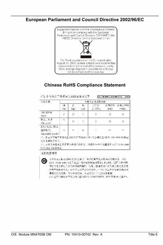
European Parliament and Council Directive 2002/96/EC
Chinese RoHS Compliance Statement

Title-6 PN: 10410-00742 Rev. A O/E Module MN4765B OM
O/E Module MN4765B OM PN: 10410-00742 Rev. A Safety-1
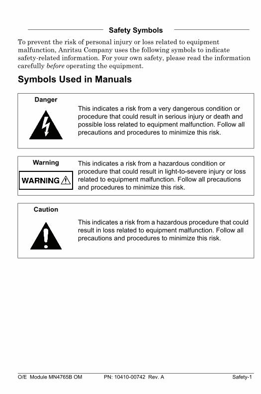
Safety Symbols
To prevent the risk of personal injury or loss related to equipment malfunction, Anritsu Company uses the following symbols to indicate safety-related information. For your own safety, please read the information carefully before operating the equipment.
Symbols Used in Manuals
DangerThis indicates a risk from a very dangerous condition or procedure that could result in serious injury or death and possible loss related to equipment malfunction. Follow all precautions and procedures to minimize this risk.
Warning This indicates a risk from a hazardous condition or procedure that could result in light-to-severe injury or loss related to equipment malfunction. Follow all precautions and procedures to minimize this risk.
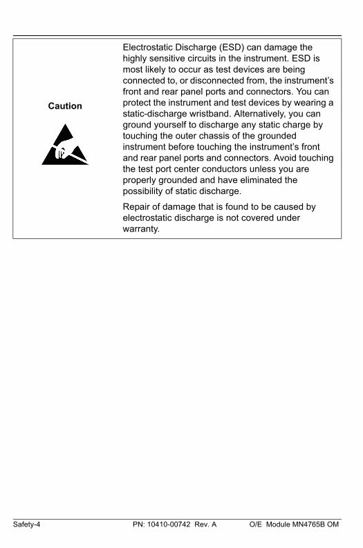
Caution
This indicates a risk from a hazardous procedure that could result in loss related to equipment malfunction. Follow all precautions and procedures to minimize this risk.
Safety-2 PN: 10410-00742 Rev. A O/E Module MN4765B OM
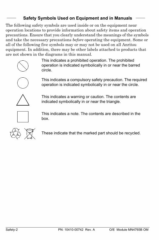
Safety Symbols Used on Equipment and in Manuals
The following safety symbols are used inside or on the equipment near operation locations to provide information about safety items and operation precautions. Ensure that you clearly understand the meanings of the symbols and take the necessary precautions before operating the equipment. Some or all of the following five symbols may or may not be used on all Anritsu equipment. In addition, there may be other labels attached to products that are not shown in the diagrams in this manual.
This indicates a prohibited operation. The prohibited operation is indicated symbolically in or near the barred circle.
This indicates a compulsory safety precaution. The required operation is indicated symbolically in or near the circle.
This indicates a warning or caution. The contents are indicated symbolically in or near the triangle.
This indicates a note. The contents are described in the box.
These indicate that the marked part should be recycled.
O/E Module MN4765B OM PN: 10410-00742 Rev. A Safety-3
For Safety
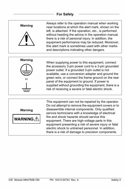
WarningAlways refer to the operation manual when working near locations at which the alert mark, shown on the left, is attached. If the operation, etc., is performed without heeding the advice in the operation manual, there is a risk of personal injury. In addition, the equipment performance may be reduced. Moreover, this alert mark is sometimes used with other marks and descriptions indicating other dangers.
WarningWhen supplying power to this equipment, connect the accessory 3-pin power cord to a 3-pin grounded power outlet. If a grounded 3-pin outlet is not available, use a conversion adapter and ground the green wire, or connect the frame ground on the rear panel of the equipment to ground. If power is supplied without grounding the equipment, there is a risk of receiving a severe or fatal electric shock.
Warning
This equipment can not be repaired by the operator. Do not attempt to remove the equipment covers or to disassemble internal components. Only qualified service technicians with a knowledge of electrical fire and shock hazards should service this equipment. There are high-voltage parts in this equipment presenting a risk of severe injury or fatal electric shock to untrained personnel. In addition, there is a risk of damage to precision components.
Safety-4 PN: 10410-00742 Rev. A O/E Module MN4765B OM
Caution
Electrostatic Discharge (ESD) can damage the highly sensitive circuits in the instrument. ESD is most likely to occur as test devices are being connected to, or disconnected from, the instrument’s front and rear panel ports and connectors. You can protect the instrument and test devices by wearing a static-discharge wristband. Alternatively, you can ground yourself to discharge any static charge by touching the outer chassis of the grounded instrument before touching the instrument’s front and rear panel ports and connectors. Avoid touching the test port center conductors unless you are properly grounded and have eliminated the possibility of static discharge.
Repair of damage that is found to be caused by electrostatic discharge is not covered under warranty.
O/E Module MN4765B OM PN: 10410-00742 Rev. A Contents-1
Table of Contents
Chapter 1—Overview
1-1 Introduction . . . . . . . . . . . . . . . . . . . . . . . . . . . . . . . . . . . . . . . . . 1-1
1-2 Related Manuals . . . . . . . . . . . . . . . . . . . . . . . . . . . . . . . . . . . . . 1-2
1-3 MN4765B Specifications . . . . . . . . . . . . . . . . . . . . . . . . . . . . . . . 1-2
1-4 MN4765B Characterization . . . . . . . . . . . . . . . . . . . . . . . . . . . . . 1-2
Characterization . . . . . . . . . . . . . . . . . . . . . . . . . . . . . . . . . . . 1-2
Re-characterization . . . . . . . . . . . . . . . . . . . . . . . . . . . . . . . . 1-2
Chapter 2—Installation
2-1 Introduction . . . . . . . . . . . . . . . . . . . . . . . . . . . . . . . . . . . . . . . . . 2-1
2-2 Unpacking and Initial Inspection . . . . . . . . . . . . . . . . . . . . . . . . . 2-1
2-3 Contents . . . . . . . . . . . . . . . . . . . . . . . . . . . . . . . . . . . . . . . . . . . 2-1
2-4 Preparation for Use . . . . . . . . . . . . . . . . . . . . . . . . . . . . . . . . . . . 2-2
Power Requirements . . . . . . . . . . . . . . . . . . . . . . . . . . . . . . . 2-3
MN4765B Measurement Setup . . . . . . . . . . . . . . . . . . . . . . . 2-4
Chapter 3—Operation
3-1 Introduction . . . . . . . . . . . . . . . . . . . . . . . . . . . . . . . . . . . . . . . . . 3-1
3-2 E/O Measurements . . . . . . . . . . . . . . . . . . . . . . . . . . . . . . . . . . . 3-1
Required Equipment. . . . . . . . . . . . . . . . . . . . . . . . . . . . . . . . 3-2
Measurement Steps . . . . . . . . . . . . . . . . . . . . . . . . . . . . . . . . 3-2
Measurement Tips . . . . . . . . . . . . . . . . . . . . . . . . . . . . . . . . . 3-4
3-3 O/E Measurements . . . . . . . . . . . . . . . . . . . . . . . . . . . . . . . . . . . 3-6
Required Equipment. . . . . . . . . . . . . . . . . . . . . . . . . . . . . . . . 3-7
Measurement Steps . . . . . . . . . . . . . . . . . . . . . . . . . . . . . . . . 3-7
Contents-2 PN: 10410-00742 Rev. A O/E Module MN4765B OM
Table of Contents (Continued)
Appendix A—Supplemental Information
A-1 Characterization Files . . . . . . . . . . . . . . . . . . . . . . . . . . . . . . . . .A-1
A-2 Optical Measurement Considerations . . . . . . . . . . . . . . . . . . . . .A-2
Laser Power and Bias Sequencing. . . . . . . . . . . . . . . . . . . . .A-2
Optical Fiber Lengths . . . . . . . . . . . . . . . . . . . . . . . . . . . . . . .A-2
Modulator Bias Control . . . . . . . . . . . . . . . . . . . . . . . . . . . . . .A-3
Notes . . . . . . . . . . . . . . . . . . . . . . . . . . . . . . . . . . . . . . . . . . .A-4
O/E Module MN4765B OM PN: 10410-00742 Rev. A 1-1
Chapter 1 — Overview
1-1 IntroductionThis manual provides general information, installation, and operating information for the Anritsu MN4765B O/E Calibration Module. The MN4765B is a characterized O/E calibration module used to make broadband measurements. Customers are required to also order an option to configure the bandwidth and wavelength coverage. The module, along with the user specified options, consists of a very fast and linear optical detector with circuitry to stabilize the temperature and bias voltage. It allows frequency domain measurements of optoelectronic components using the MS4640B VectorStar series Vector Network Analyzer (VNA).
Throughout this manual, the terms MN4765B with user specified options and O/E Calibration Module will be used interchangeably to refer to the MN4765B Features.
• Fast and accurate optoelectronic measurements: The MS4640B VectorStar series VNAs, when calibrated using the MN4765B module, enable error-corrected Transfer Function, Group Delay, and Return Loss measurements of E/O and O/E components and subsystems.
• National Institute of Standards and Technology derived characterization: Magnitude and phase characterization is obtained using a primary standard characterized by NIST and held in the Anritsu Calibration Lab. The magnitude and phase data is provided on a USB with the module.
• Temperature Stable: The MN4765B is thermally stabilized to eliminate drift in photodiode performance over temperature.
• Internal Biasing: Accurate bias voltage to the photodiode is maintained internally. An external, multi-country, AC adapter is included for easy operation.
• High Linearity: Linear operating range to +6 dBm for transfer function measurement uncertainties of < 0.45 dB at 50 GHz and < 0.7 dB at 70 GHz. (Typical specifications for Option 70, MN4765B-0070)
• High Responsivity: 0.7 A/W (Typical specifications for Option 70, MN4765B-0070)
1-2 PN: 10410-00742 Rev. A O/E Module MN4765B OM
1-2 Related Manuals Overview
1-2 Related ManualsThis manual provides operating instructions for the MN4765B O/E Calibration Module. Refer to the following manuals for detailed operating instructions and application notes when using the MS4640B VectorStar Vector Network Analyzer:
• Model MS4640B VectorStar Vector Network Analyzer Operation Manual, P/N: 10410-00317, Revision B or later
• Electrical-to-Optical and Optical-to-Electrical (E/O and O/E) converter measurements Application Note 11410-00798
1-3 MN4765B SpecificationsRefer to the 11410-00843 MN4765B Technical Data Sheet.
1-4 MN4765B Characterization The accuracy and longevity of any characterization depends on the ability to take care of the module, especially the connectors. Understanding the maximum rated specifications and general cleaning of the electrical and optical connectors is essential.
Characterization
The MN4765B module is serialized and comes with a characterization in relative magnitude and phase with a specified uncertainty from 70 kHz up to 110 GHz (depending on the option ordered). A copy of the characterization can be found on the USB memory device that ships with the module. If a replacement copy of the characterization is required, contact Anritsu Customer Service at: www.anritsu.com
Re-characterization
The MN4765B calibration certificate contains the recommended calibration interval. Any module outside of its calibration interval should be sent to Anritsu Customer Service for re-characterization. The Anritsu Calibration Lab will check the re-characterization against the original specifications.
O/E Module MN4765B OM PN: 10410-00742 Rev. A 2-1
Chapter 2 — Installation
2-1 IntroductionThis chapter provides installation instructions for the MN4765B O/E Calibration Module. It includes information on initial inspection, preparation for use, storage, and reshipment.
2-2 Unpacking and Initial InspectionThe MN4765B ships in two protective boxes, one external and one internal. Inspect the shipping container for damage. If the shipping container or cushioning material is damaged, retain until the contents of the shipment have been checked against the packing list and the module has been checked for mechanical and electrical operation. If the shipment is incomplete or if the test set is damaged mechanically or electrically, notify your local sales representative or Anritsu Customer Service. If either the shipping container is damaged or the cushioning material shows signs of stress, notify the carrier as well as Anritsu. Keep the shipping materials for the carrier's inspection.
2-3 ContentsThe external box holds the internal box plus a power cord to match the specific country code for utility outlets. The internal box contains the MN4765B and all the necessary equipment to safely and correctly handle the calibration module. The items included are:
• MN4765B with user specified options
• AC Adapter and Power Cord
• Calibration Certificate
• USB memory device (copy of the MN4765B calibration data)
2-2 PN: 10410-00742 Rev. A O/E Module MN4765B OM
2-4 Preparation for Use Installation
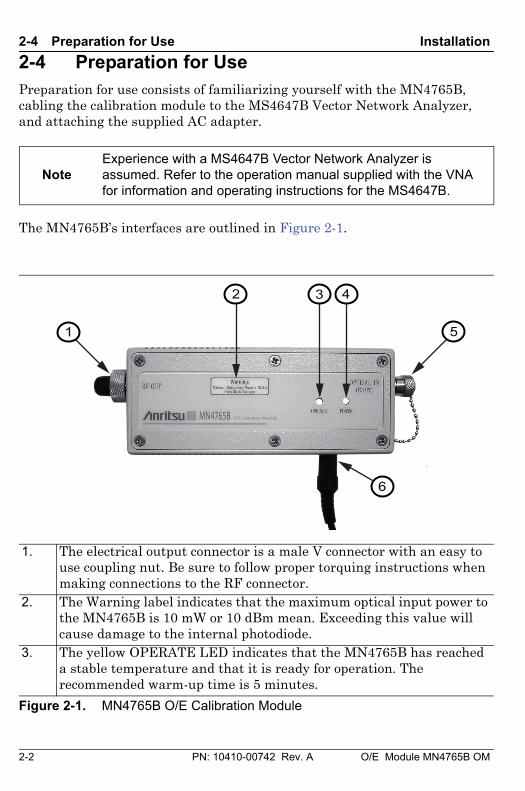
2-4 Preparation for UsePreparation for use consists of familiarizing yourself with the MN4765B, cabling the calibration module to the MS4647B Vector Network Analyzer, and attaching the supplied AC adapter.
The MN4765B’s interfaces are outlined in Figure 2-1.
NoteExperience with a MS4647B Vector Network Analyzer is assumed. Refer to the operation manual supplied with the VNA for information and operating instructions for the MS4647B.
1. The electrical output connector is a male V connector with an easy touse coupling nut. Be sure to follow proper torquing instructions whenmaking connections to the RF connector.
2. The Warning label indicates that the maximum optical input power to the MN4765B is 10 mW or 10 dBm mean. Exceeding this value will cause damage to the internal photodiode.
3. The yellow OPERATE LED indicates that the MN4765B has reached a stable temperature and that it is ready for operation. The recommended warm-up time is 5 minutes.
Figure 2-1. MN4765B O/E Calibration Module
32
5
4
6
1
MN4765B O/E Calibration Module
O/E Module MN4765B OM PN: 10410-00742 Rev. A 2-3
Installation 2-4 Preparation for Use
Power Requirements
The MN4765B O/E Calibration Module accepts 85 VAC to 240 VAC, 47 Hz to 63 Hz, single-phase power. The calibration module is intended for Installation Category (Over Voltage Category) II.
The following procedure provides the steps necessary to connect the MN4765B calibration module to the MS4647B Vector Network Analyzer.
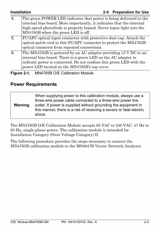
4. The green POWER LED indicates that power is being delivered to the internal bias board. More importantly, it indicates that the internal high-speed photodiode is properly biased. Never input light into the MN4765B when the green LED is off.
5. FC/APC optical input connector with protective dust cap. Attach the optical patch cord to this FC/APC connector to protect the MN4765B optical connector from repeated connections.
6. The MN4765B is powered by an AC adapter providing 12 V DC to an internal bias board. There is a green LED on the AC adapter to indicate power is connected. Do not confuse this green LED with the power LED located on the MN4765B’s top cover.
Warning
When supplying power to this calibration module, always use a three-wire power cable connected to a three-wire power line outlet. If power is supplied without grounding the equipment in this manner, there is a risk of receiving a severe or fatal electric shock.
Figure 2-1. MN4765B O/E Calibration Module
2-4 PN: 10410-00742 Rev. A O/E Module MN4765B OM
2-4 Preparation for Use Installation
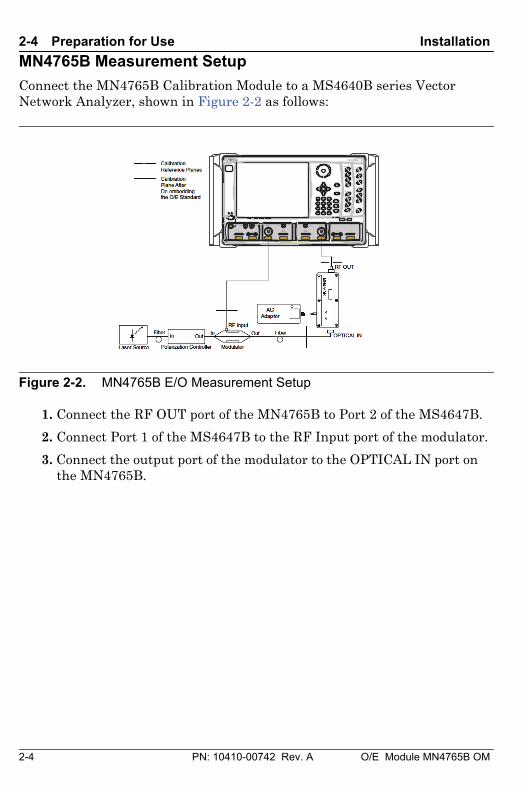
MN4765B Measurement Setup
Connect the MN4765B Calibration Module to a MS4640B series Vector Network Analyzer, shown in Figure 2-2 as follows:
1. Connect the RF OUT port of the MN4765B to Port 2 of the MS4647B.
2. Connect Port 1 of the MS4647B to the RF Input port of the modulator.
3. Connect the output port of the modulator to the OPTICAL IN port on the MN4765B.
Figure 2-2. MN4765B E/O Measurement Setup
+27 dBm MAX AVOID STATIC DISCHARGEALL PORTS: CAUTION
Standby Operate
Frequency
Power
Sweep
Avg
Response
Display
Scale
Marker
Channel
Trace
Measurement
Calibration
Application
File
System
Help
Preset
O/E Module MN4765B OM PN: 10410-00742 Rev. A 3-1
Chapter 3 — Operation
3-1 IntroductionThis chapter provides information on the operation of the MN4765B O/E Calibration Module.
3-2 E/O MeasurementsE/O converters modulate an electrical signal onto light to be sent over fiber links. The performance of modulators and optical transmitters is key to determining the maximum data rate achievable in an optical communication link. These devices are generally characterized in terms of:
• Modulation Bandwidth (transfer function or responsivity)
• Return Loss
• Phase Linearity
• Group Delay
The optical stimulus to the modulator is provided by an external laser source. The VNA supplies a swept microwave signal over the frequency range of interest to the modulator. The MN4765B then converts the modulated optical signal back to an electrical signal that is measured by the VNA. An electrical calibration is first performed on the VNA to remove the unwanted effects of the VNA, cables, and other components in the measurement path.
The next step is to remove (de-embed) the photodiode’s known response to reveal the performance of the E/O converter. The de-embedding of the photodiode response is performed using the VNA’s internal E/O application menu. This process requires a characterization file for the photodiode in the s2p format.
The characterization file is provided on USB memory device along with the Anritsu MN4765B O/E Calibration Module. Once the response of the photodiode is removed, the S21 measurement displays the modulator’s transfer function (ratio of modulated optical output to the electrical input signal). The 3 dB bandwidth, phase linearity, and group delay of the modulator can be determined from this transfer function.
3-2 PN: 10410-00742 Rev. A O/E Module MN4765B OM
3-2 E/O Measurements Operation
Required Equipment
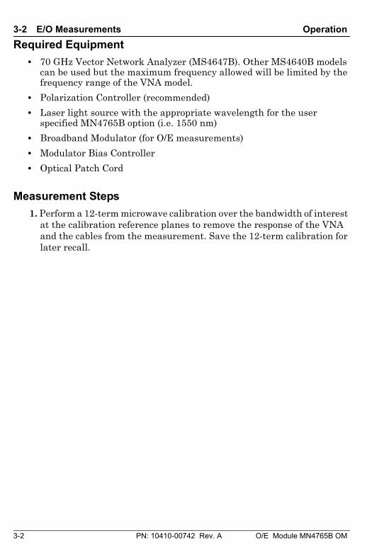
• 70 GHz Vector Network Analyzer (MS4647B). Other MS4640B models can be used but the maximum frequency allowed will be limited by the frequency range of the VNA model.
• Polarization Controller (recommended)
• Laser light source with the appropriate wavelength for the user specified MN4765B option (i.e. 1550 nm)
• Broadband Modulator (for O/E measurements)
• Modulator Bias Controller
• Optical Patch Cord
Measurement Steps
1. Perform a 12-term microwave calibration over the bandwidth of interest at the calibration reference planes to remove the response of the VNA and the cables from the measurement. Save the 12-term calibration for later recall.
O/E Module MN4765B OM PN: 10410-00742 Rev. A 3-3
Operation 3-2 E/O Measurements
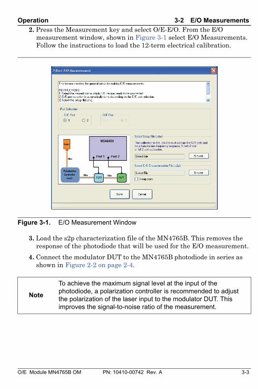
2. Press the Measurement key and select O/E-E/O. From the E/O measurement window, shown in Figure 3-1 select E/O Measurements. Follow the instructions to load the 12-term electrical calibration.
3. Load the s2p characterization file of the MN4765B. This removes the response of the photodiode that will be used for the E/O measurement.
4. Connect the modulator DUT to the MN4765B photodiode in series as shown in Figure 2-2 on page 2-4.
Figure 3-1. E/O Measurement Window
Note
To achieve the maximum signal level at the input of the photodiode, a polarization controller is recommended to adjust the polarization of the laser input to the modulator DUT. This improves the signal-to-noise ratio of the measurement.
3-4 PN: 10410-00742 Rev. A O/E Module MN4765B OM
3-2 E/O Measurements Operation
Measurement Tips
Most E/O and O/E fiber optic components will exhibit some polarization dependence. Understanding the effects of polarization is essential to maximizing measurement efficiency. Stability is another important concern. Standard single mode fibers can alter polarization states simply by adding stress to the fiber. The following tips can help enhance the measurements of E/O and O/E components:
• Measurement dynamic range can be maximized using a simple polarization controller before a polarization sensitive device. The VNA can be used to monitor the maximum RF output level as the polarization is adjusted.
• Polarization Maintaining Fiber (PMF) is an easy way to minimize polarization changes as a result of fiber turns and bends.
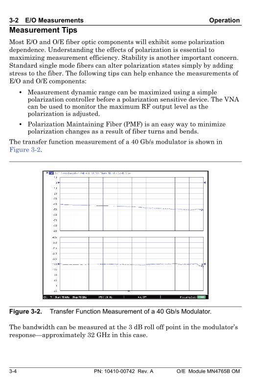
The transfer function measurement of a 40 Gb/s modulator is shown in Figure 3-2.
The bandwidth can be measured at the 3 dB roll off point in the modulator’s response—approximately 32 GHz in this case.
Figure 3-2. Transfer Function Measurement of a 40 Gb/s Modulator.
O/E Module MN4765B OM PN: 10410-00742 Rev. A 3-5
Operation 3-2 E/O Measurements
Similarly, phase and group delay measurements of the modulator can also be made by selecting the appropriate graph type. Phase is shown as part of Figure 3-2 but a separate phase graph type or a group delay graph type can also be selected.
Phase measurements are generally comprised of multiple phase transitions due to the electrical length of the DUT. A representation of phase linearity through the device can be obtained by removing the fixed electrical length. The VectorStar VNA's reference plane adjustment can be used to compensate for the phase change over frequency to display the variation from linear phase. By measuring S11, the electrical input impedance (for example, return loss of the modulator) can also be characterized. Analysis of the S11 data over distance, using the VNA’s time domain function, can help in locating discontinuities and imperfections in the modulator.
3-6 PN: 10410-00742 Rev. A O/E Module MN4765B OM
3-3 O/E Measurements Operation
3-3 O/E MeasurementsThe setup shown in Figure 2-2 on page 2-4 can also be applied to O/E measurements of a photodiode or photo-receiver DUT. Photodiodes demodulate the electrical signal from the optically modulated light in a fiber optic transmission network. An external laser source, used with a characterized modulator, provides the input to the O/E DUT. The response of the characterized modulator is de-embedded from the setup using the O/E application menu. The characterization file for the modulator can be generated using the MN4765B. See Appendix A for instructions on generating an s2p file.
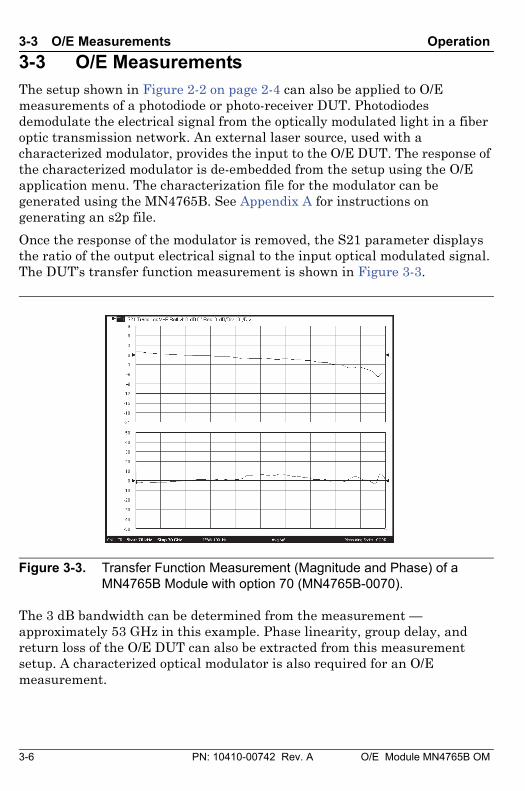
Once the response of the modulator is removed, the S21 parameter displays the ratio of the output electrical signal to the input optical modulated signal. The DUT’s transfer function measurement is shown in Figure 3-3.
The 3 dB bandwidth can be determined from the measurement — approximately 53 GHz in this example. Phase linearity, group delay, and return loss of the O/E DUT can also be extracted from this measurement setup. A characterized optical modulator is also required for an O/E measurement.
Figure 3-3. Transfer Function Measurement (Magnitude and Phase) of a MN4765B Module with option 70 (MN4765B-0070).
O/E Module MN4765B OM PN: 10410-00742 Rev. A 3-7
Operation 3-3 O/E Measurements
Required Equipment
Refer to the required E/O measurements equipment listed in Section “Required Equipment” on page 3-2.
Measurement Steps
1. Perform a 12-term calibration on the VNA over the frequency range of interest. Save the calibration for later recall.
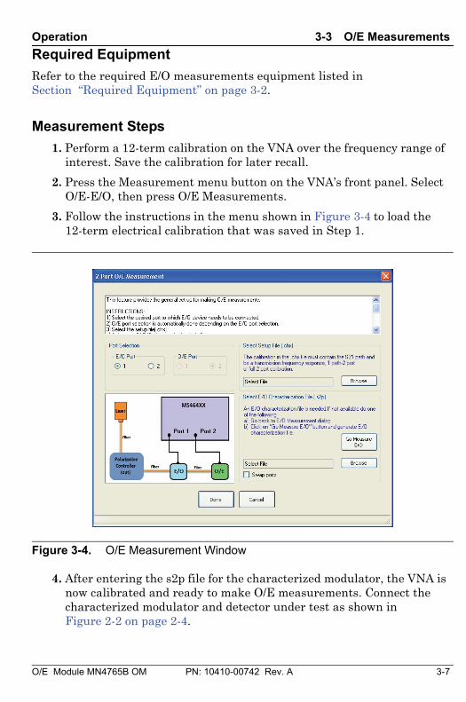
2. Press the Measurement menu button on the VNA’s front panel. Select O/E-E/O, then press O/E Measurements.
3. Follow the instructions in the menu shown in Figure 3-4 to load the 12-term electrical calibration that was saved in Step 1.
4. After entering the s2p file for the characterized modulator, the VNA is now calibrated and ready to make O/E measurements. Connect the characterized modulator and detector under test as shown in Figure 2-2 on page 2-4.
Figure 3-4. O/E Measurement Window
3-8 PN: 10410-00742 Rev. A O/E Module MN4765B OM
3-3 O/E Measurements Operation
O/E Module MN4765B OM PN: 10410-00742 Rev. A A-1
Appendix A — Supplemental Information
A-1 Characterization FilesThe MN4765B O/E Calibration Module can be used to calibrate an E/O device, usually an external modulator, to be used in O/E measurements. The following calibration procedure guides you through an E/O calibration and produces an s2p file that represents the E/O standard:
1. Perform a 12-term calibration over the frequency range of interest. Save this calibration to USB memory device.
2. Press the Measurement key on the front panel.
• Select O/E-E/O.
• Select O/E Measurements.
• When asked to load the original cal file, select the calibration that was saved in Step 1.
3. After loading the VNA calibration, load the s2p file for the MN4765B.
4. Connect the optical components together as shown in Figure 2-2 on page 2-4.
• Apply bias to the photodiode and to the modulator before turning on the laser.
5. Connect the AC adaptor to the MN4765B. Ensure that the calibration module is powered up and that the yellow OPERATE LED is illuminated.
6. Turn the laser ON and adjust the polarization to achieve the maximum signal level. To enhance the response and reduce the signal-to-noise ratio, increase the laser’s power and the VNA’s averaging count, and lower the I.F. bandwidth.
• At this point, the laser is on maximum power. The S21 parameter should show an E/O response over the entire frequency range of the calibration. The next steps will generate the modulator’s s2p file.
7. From the Display Menu, set the VNA to display Log Magnitude and Phase. From the Response menu select S21.
A-2 PN: 10410-00742 Rev. A O/E Module MN4765B OM
A-2 Optical Measurement Considerations Supplemental Information
8. The screen should now display S21 (magnitude and phase) for the E/Omodulator. The data can then be stored as an s2p file by selecting File,Save Data and by appropriately setting the file format and naming thefile.
A-2 Optical Measurement Considerations
Laser Power and Bias Sequencing
Always make sure the MN4765B is biased properly before turning the laser on.
Optical Fiber Lengths
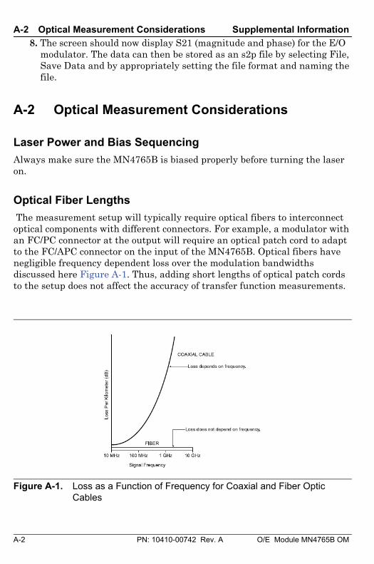
The measurement setup will typically require optical fibers to interconnect optical components with different connectors. For example, a modulator with an FC/PC connector at the output will require an optical patch cord to adapt to the FC/APC connector on the input of the MN4765B. Optical fibers have negligible frequency dependent loss over the modulation bandwidths discussed here Figure A-1. Thus, adding short lengths of optical patch cords to the setup does not affect the accuracy of transfer function measurements.
Figure A-1. Loss as a Function of Frequency for Coaxial and Fiber Optic Cables
O/E Module MN4765B OM PN: 10410-00742 Rev. A A-3
Supplemental Information A-2 Optical Measurement Considerations
Modulator Bias Control
Lithium Niobate modulators are generally biased using a modulator bias controller (MBC) to control the operating point of the modulator. When biased in quadrature, the input RF signal linearly modulates the optical carrier. Note that when an MBC is applied, it must be designed for small signal operation. The default power from the Port 1 test port is –7 dBm for the 70 GHz VNA MS4647B. This results in a modulation depth of < 10%.
A DC power supply can be used in place of an MBC. However, the stability of the S21 measurement may be degraded due to drift in the modulator’s bias point.

Notes

Notes

Anritsu Company490 Jarvis Drive
Morgan Hill, CA 95037-2809USA
Anritsu utilizes recycled paper and environmentally conscious inks and toner.
Пожалуйста, обращайтесь:
info@ radar1.ru
РОССИЯ, 198152, Санкт-Петербург
Краснопутиловская ул., д.25
Тел./факс +7 (812) 600-48-89
Тел.: +7 (812) 375-32-44
www.radar1.ru
НПО "РАДАР"Официальный представитель и
авторизованный сервис-центр
Anritsu Corporation