Embed Size (px)
Citation preview
1 von 9
Fakultät Maschinenwesen, Professur Materialwissenschaft und Nanotechnik
Berlin, 20.03.2015 11:45 – 12:00
1
Ab-initio model of extended CNT-metal contacts
Artem Fediai, Dmitry Ryndyk and Gianaurelio Cuniberti
2 von 92
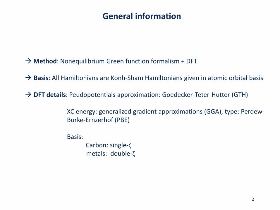
General information
Method: Nonequilibrium Green function formalism + DFT
Basis: All Hamiltonians are Konh-Sham Hamiltonians given in atomic orbital basis
DFT details: Peudopotentials approximation: Goedecker-Teter-Hutter (GTH)
XC energy: generalized gradient approximations (GGA), type: Perdew-Burke-Ernzerhof (PBE)
Basis: Carbon: single-ζmetals: double-ζ
3 von 93
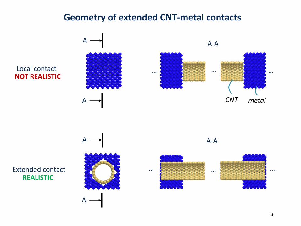
Geometry of extended CNT-metal contacts
…… …Local contact
A A-A
…… …Extended contactREALISTIC
A
A
A
NOT REALISTIC
A-A
metalCNT
4 von 94
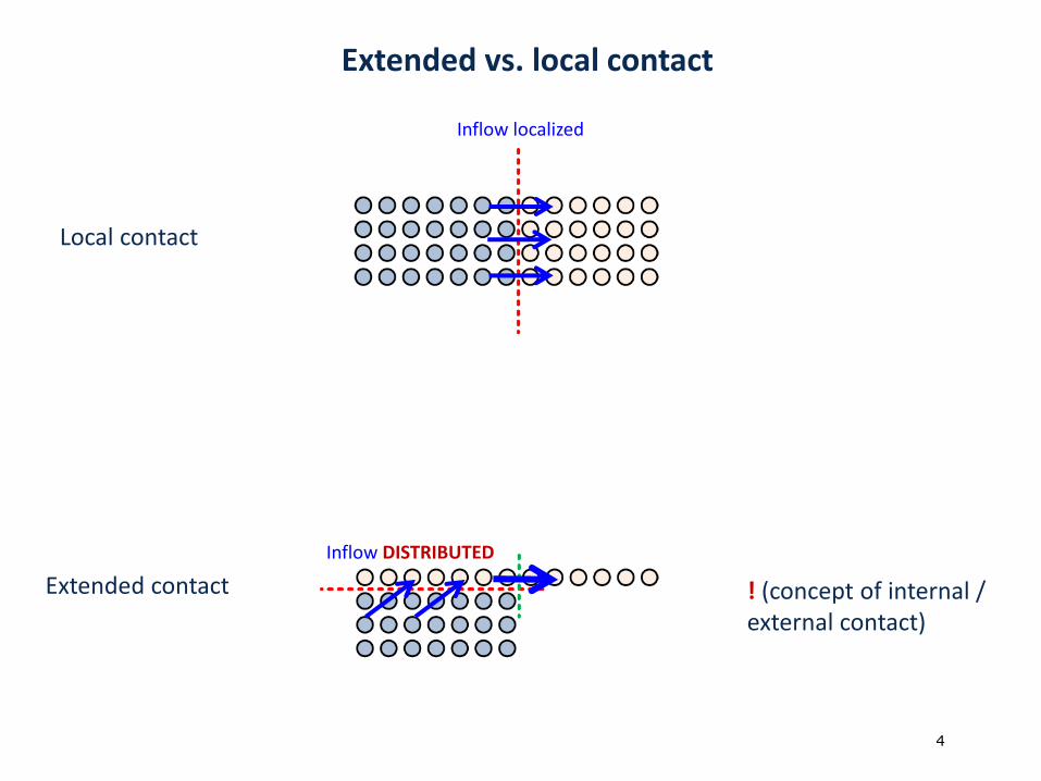
Extended vs. local contact
Inflow DISTRIBUTED
Inflow localized
! (concept of internal / external contact)
Local contact
Extended contact
5 von 95
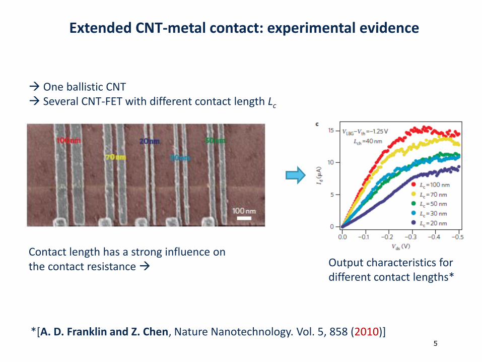
Extended CNT-metal contact: experimental evidence
*[A. D. Franklin and Z. Chen, Nature Nanotechnology. Vol. 5, 858 (2010)]
One ballistic CNT Several CNT-FET with different contact length Lc
Contact length has a strong influence on the contact resistance Output characteristics for
different contact lengths*
6 von 96
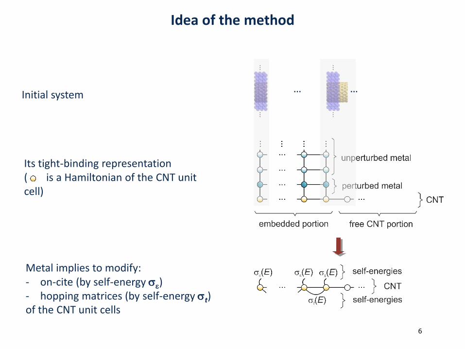
Idea of the method
… …Initial system
Its tight-binding representation( is a Hamiltonian of the CNT unit cell)
Metal implies to modify:- on-cite (by self-energy se)- hopping matrices (by self-energy st)of the CNT unit cells
7 von 97
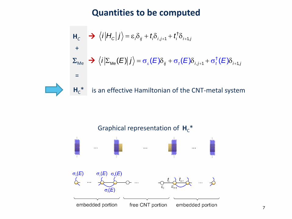
Quantities to be computed
HC*
HC
SMe
e †, 1 1,C i ij i i j i i ji H j t t
e s sS s Me , 1 1
†
,( ) ( ) () )( ij i j i jt tE E Ei E j
+
=
Graphical representation of
is an effective Hamiltonian of the CNT-metal system
HC*
8 von 98
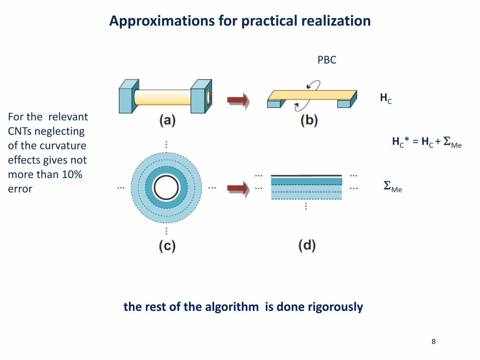
Approximations for practical realization
HC* = HC + SMe
HC
SMe
PBC
the rest of the algorithm is done rigorously
For the relevant CNTs neglecting of the curvature effects gives not more than 10% error
9 von 99
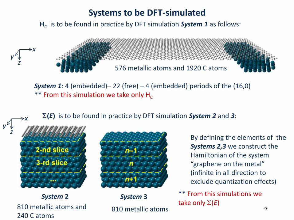
Systems to be DFT-simulatedHC is to be found in practice by DFT simulation System 1 as follows:
System 1: 4 (embedded)– 22 (free) – 4 (embedded) periods of the (16,0) ** From this simulation we take only HC
576 metallic atoms and 1920 C atomsz
xy
System 2 System 3
By defining the elements of the Systems 2,3 we construct the Hamiltonian of the system “graphene on the metal”(infinite in all direction to exclude quantization effects)
z
xy
810 metallic atoms and 240 C atoms
810 metallic atoms
** From this simulations we take only S(E)
S(E) is to be found in practice by DFT simulation System 2 and 3:
10 von 910
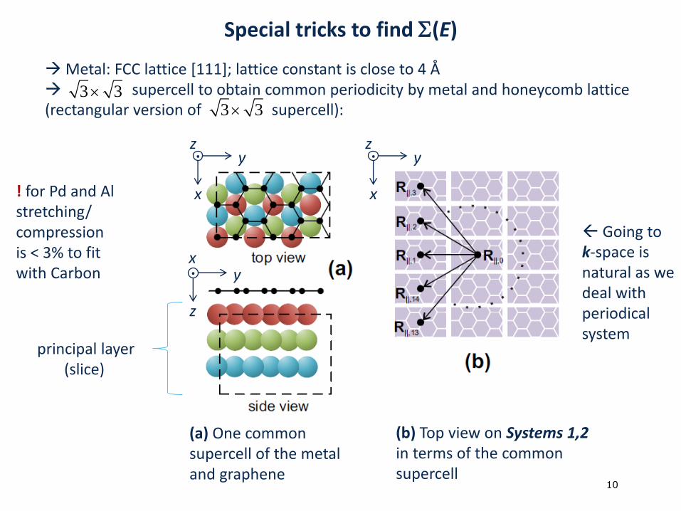
Metal: FCC lattice [111]; lattice constant is close to 4 Å supercell to obtain common periodicity by metal and honeycomb lattice (rectangular version of supercell):
(a) One common supercell of the metal and graphene
x
z. y
x
z. y
z
x. y
(b) Top view on Systems 1,2 in terms of the common supercell
principal layer(slice)
Going to k-space is natural as we deal with periodical system
3 33 3
! for Pd and Al stretching/ compression is < 3% to fit with Carbon
Special tricks to find S(E)
11 von 911
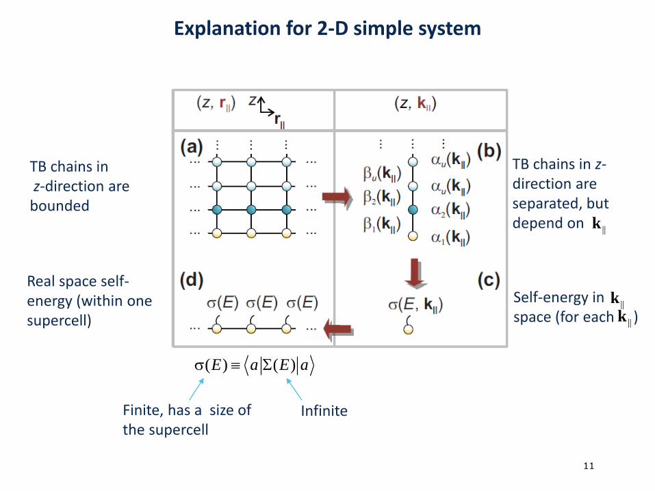
Explanation for 2-D simple system
TB chains inz-direction are
bounded
TB chains in z-direction are separated, but depend on
Self-energy in space (for each )
Real space self-energy (within one supercell)
( ) ( )s SE a E a
InfiniteFinite, has a size of the supercell
||k
||k
||k
12 von 912
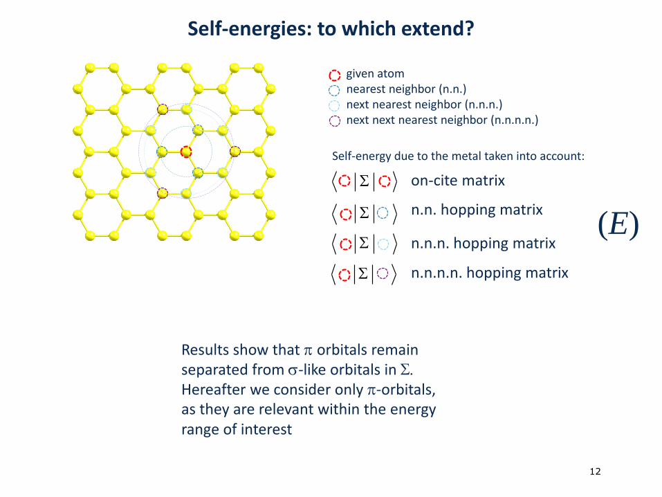
Self-energies: to which extend?
given atomnearest neighbor (n.n.) next nearest neighbor (n.n.n.)next next nearest neighbor (n.n.n.n.)
Self-energy due to the metal taken into account:
S
S
S
S
on-cite matrix
n.n. hopping matrix
n.n.n. hopping matrix
n.n.n.n. hopping matrix
Results show that p orbitals remainseparated from s-like orbitals in S.Hereafter we consider only p-orbitals, as they are relevant within the energy range of interest
(E)
13 von 913
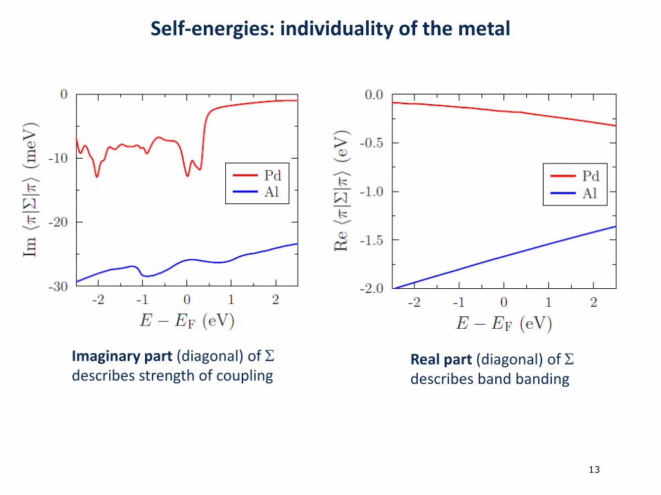
Self-energies: individuality of the metal
Imaginary part (diagonal) of Sdescribes strength of coupling
Real part (diagonal) of Sdescribes band banding
14 von 914
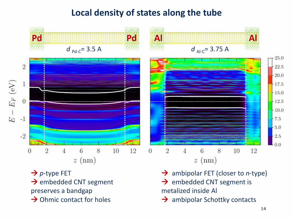
Local density of states along the tube
d Pd-C= 3.5 A d Al-C= 3.75 A
Pd AlPd Al
p-type FET embedded CNT segment preserves a bandgap Ohmic contact for holes
ambipolar FET (closer to n-type) embedded CNT segment is metalized inside Al ambipolar Schottky contacts
15 von 915
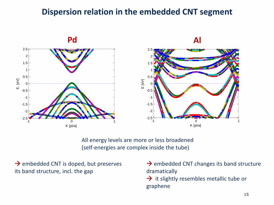
Dispersion relation in the embedded CNT segment
embedded CNT is doped, but preserves its band structure, incl. the gap
embedded CNT changes its band structure dramatically it slightly resembles metallic tube or graphene
Pd Al
-1 0 1-2.5
-2
-1.5
-1
-0.5
0
0.5
1
1.5
2
2.5
K [pi/a]
E [
eV
]
-1 0 1-2.5
-2
-1.5
-1
-0.5
0
0.5
1
1.5
2
2.5
K [pi/a]
E,
[eV
]
All energy levels are more or less broadened (self-energies are complex inside the tube)
16 von 916
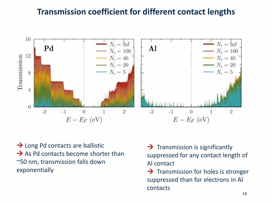
Transmission coefficient for different contact lengths
Long Pd contacts are ballistic As Pd contacts become shorter than ~50 nm, transmission falls down exponentially
Transmission is significantly suppressed for any contact length of Al contact Transmission for holes is stronger suppressed than for electrons in Al contacts
17 von 917
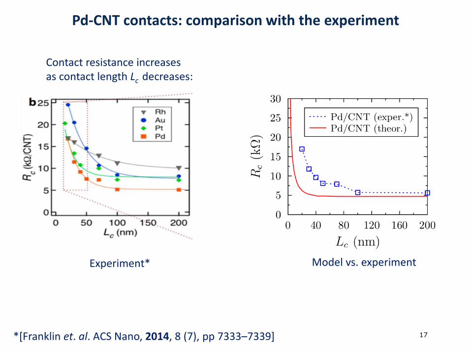
Pd-CNT contacts: comparison with the experiment
*[Franklin et. al. ACS Nano, 2014, 8 (7), pp 7333–7339]
Contact resistance increases as contact length Lc decreases:
Model vs. experimentExperiment*
18 von 918
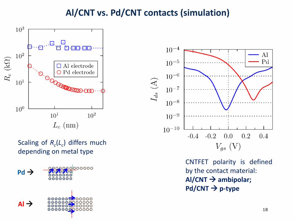
Al/CNT vs. Pd/CNT contacts (simulation)
CNTFET polarity is definedby the contact material:Al/CNT ambipolar;Pd/CNT p-type
Scaling of Rc(Lc) differs muchdepending on metal type
Pd
Al
19 von 919
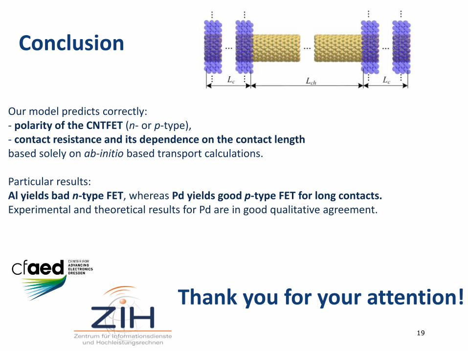
Conclusion
Our model predicts correctly:- polarity of the CNTFET (n- or p-type), - contact resistance and its dependence on the contact lengthbased solely on ab-initio based transport calculations.
Particular results:Al yields bad n-type FET, whereas Pd yields good p-type FET for long contacts.Experimental and theoretical results for Pd are in good qualitative agreement.
Thank you for your attention!