Embed Size (px)
Citation preview
Yagi-Uda antenna From Wikipedia, the free encyclopedia
Drawing of Yagi-Uda VHF television antenna from 1954, used for analog channels 2-4, 47 - 68
MHz. It has five elements: three directors (to left) one reflector (to right) and a driven element
which is a folded dipole to match the 300Ω impedance of the twin leadfeedline. Its beam
direction (direction of greatest sensitivity) is off the support boom to the left.
A modern high gain UHF Yagitelevision antenna. It has 17 directors, and 4 reflectors shaped as
a corner reflector.
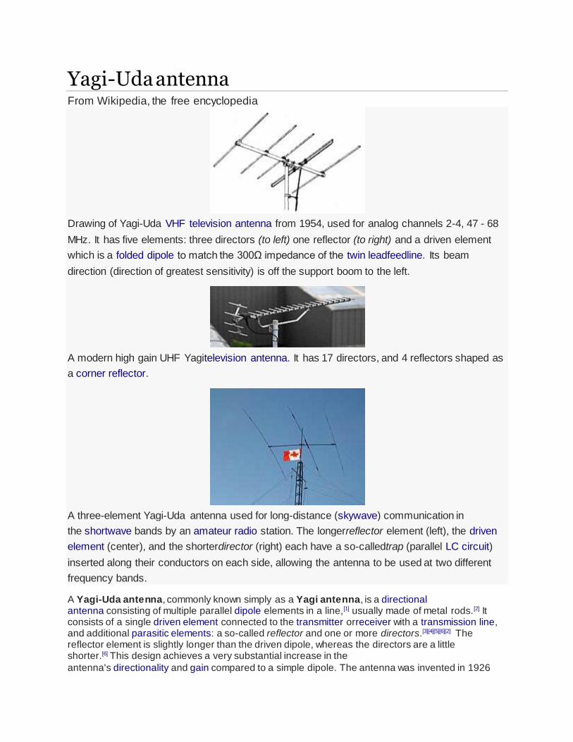
A three-element Yagi-Uda antenna used for long-distance (skywave) communication in
the shortwave bands by an amateur radio station. The longerreflector element (left), the driven
element (center), and the shorterdirector (right) each have a so-calledtrap (parallel LC circuit)
inserted along their conductors on each side, allowing the antenna to be used at two different
frequency bands.
A Yagi-Uda antenna, commonly known simply as a Yagi antenna, is a directional antenna consisting of multiple parallel dipole elements in a line,[1] usually made of metal rods.[2] It consists of a single driven element connected to the transmitter orreceiver with a transmission line, and additional parasitic elements: a so-called reflector and one or more directors.[3][4][5][6][2] The reflector element is slightly longer than the driven dipole, whereas the directors are a little shorter.[6] This design achieves a very substantial increase in the
antenna's directionality and gain compared to a simple dipole. The antenna was invented in 1926

by Shintaro Uda of Tohoku Imperial University, Japan,[4] with a lesser role played by his colleague Hidetsugu Yagi.[3][7] However the "Yagi" name has become more familiar with the name of Uda often omitted. This appears to have been due to Yagi filing a patent on the idea in Japan without Uda's name in it, and later transferring the patent to the Marconi Company in the UK.[8] Yagi antennas were first widely used during World War II in radar systems by the British, US and Germans.[7] After the war they saw extensive development as home television antennas.
Also called a "beam antenna",[6] the Yagi is very widely used as a high-gain antenna on the HF, VHF and UHF bands.[6][5] It has moderate gain which depends on the number of elements used, typically limited to about 17 dBi, [5] linear polarization,[5]unidirectional (end-fire) beam pattern[5] with high front-to-back ratio of up to 20 db. and is lightweight, inexpensive and simple to construct.[5] The bandwidth is narrow, a few percent of the center frequency, and decreases with increasing gain,[6][5] so it is often used in fixed-frequency applications. The largest and most well-known use is as rooftop terrestrial television antennas,[5] but it is also used for point-to-point fixed communication links,[2] in radar antennas,[6] and for long distance shortwavecommunication by shortwave broadcasting stations and radio amateurs.[2]

History[edit]
The Yagi-Uda antenna was invented in 1926 by Shintaro Uda of Tohoku Imperial
University,[4] Sendai, Japan, with the collaboration of Hidetsugu Yagi, also of Tohoku
Imperial University.[3] Yagi and Uda published their first report on the wave projector
directional antenna. Yagi demonstrated a proof of concept, but the engineering
problems proved to be more onerous than conventional systems.[14]
Yagi published the first English-language reference on the antenna in a 1928 survey
article on short wave research in Japan and it came to be associated with his name.
However, Yagi always acknowledged Uda's principal contribution to the design, and the
proper name for the antenna is, as above, the Yagi-Uda antenna (or array).
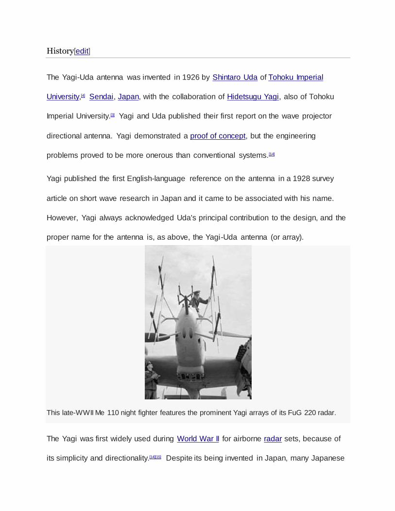
This late-WWII Me 110 night fighter features the prominent Yagi arrays of its FuG 220 radar.
The Yagi was first widely used during World War II for airborne radar sets, because of
its simplicity and directionality.[14][15] Despite its being invented in Japan, many Japanese
radar engineers were unaware of the design until very late in the war, partly due to
rivalry between the Army and Navy. The Japanese military authorities first became
aware of this technology after the Battle of Singapore when they captured the notes of a
British radar technician that mentioned "yagi antenna". Japanese intelligence officers
did not even recognise that Yagi was a Japanese name in this context. When
questioned, the technician said it was an antenna named after a Japanese
professor.[16] (This story is analogous to the story of American intelligence officers
interrogating German rocket scientists and finding out that Robert Goddard was the real
pioneer of rocket technology even though he was not well known in the US at that time.)
A horizontally polarized array can be seen under the leading edge of Grumman TBF
Avenger carrier-based US Navy aircraft and the Consolidated PBY Catalina long range
patrol seaplane. Vertically polarized arrays can be seen on the cheeks of theP-61 and
on the nose cones of many WWII aircraft, notably the Lichtenstein radar-equipped
examples of the German Junkers Ju 88R-1 fighter-bomber, and the British Bristol
Beaufighter night-fighter and Short Sunderland flying-boat. Indeed, the latter had so
many antenna elements arranged on its back - in addition to its formidable turreted
defensive armament in the nose and tail, and atop the hull - it was nicknamed
the fliegendes Stachelschwein, or "Flying Porcupine" by German airmen.[17] The
experimental Morgenstern German AI VHF-band radar antenna of 1943-44 used a
"double-Yagi" structure from its 90° angled pairs of Yagi antennas, making it possible to
fair the array within a conical, rubber-covered plywood radome on an aircraft's nose,
with the extreme tips of the Morgenstern's antenna elements protruding from the
radome's surface, with an NJG 4 Ju 88G-6 of the wing's staff flight using it late in the
war for its Lichtenstein SN-2 AI radar.[18]
Yagi-Uda antennas are routinely made with rather high gains (over 10dB) making them
a common choice for directional antennas especially in VHF and UHF communications
systems where a narrowband antenna is acceptable. Only at higher UHF and
microwave frequencies are parabolic reflectors and other so-called aperture antennas of
a practical size; these can easily achieve yet higher gains.
The Yagi-Uda antenna was named an IEEE Milestone in 1995.[19]
What is the origin of the antenna? I'm ruling out such early devices as compasses, because while they in some sense receive a magnetic field, it is not an electromagnetic
field. Ben Franklin's kite experiment wasn't quite an antenna, as that captured
lightning discharge, which is a direct current path where the energy is not transferred independent of the medium it travels. The human eye of course receives high
frequency electromagnetic waves (light, to the layman). Technically the eye could be
classified as an antenna; however since it can't transmit waves, it is really a sensor, so
I'll exclude that as well.
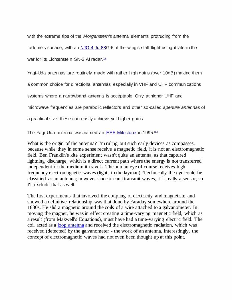
The first experiments that involved the coupling of electricity and magnetism and
showed a definitive relationship was that done by Faraday somewhere around the 1830s. He slid a magnetic around the coils of a wire attached to a galvanometer. In
moving the magnet, he was in effect creating a time-varying magnetic field, which as
a result (from Maxwell's Equations), must have had a time-varying electric field. The coil acted as a loop antenna and received the electromagnetic radiation, which was
received (detected) by the galvanometer - the work of an antenna. Interestingly, the
concept of electromagnetic waves had not even been thought up at this point.

A painting of Michael Faraday. Being a great experimentalist, he naturally dabbled in chemistry, shown here.
Heinrich Hertz developed a wireless communication system in which he forced an electrical spark to occur in the gap of a dipole antenna. He used a loop antenna as a
receiver, and observed a similar disturbance. This was 1886. By 1901, Marconi was
sending information across the atlantic. For a transmit antenna, he used several
vertical wires attached to the ground. Across the Atlantic Ocean, the receive antenna was a 200 meter wire held up by a kite [1].
In 1906, Columbia University had an Experimental Wireless Station where they used a transmitting aerial cage. This was a cage made up of wires and suspended in the air,
resembling a cage [2].
A rough outline of some major antennas and their discovery/fabrication dates are
listed:
Yagi-Uda Antenna, 1920s
Horn antennas, 1939. Interesting, the early antenna literature discussed waveguides
as "hollow metal pipes".
Antenna Arrays, 1940s
Parabolic Reflectors, late 1940s, early 1950s? Just a guess.
Patch Antennas, 1970s. PIFA, 1980s.
Current research on antennas involves metamaterials (materials that have engineered dielectric and magnetic constants, that can be simultaneously negative, allowing for
interesting properties like a negative index of refraction). Other research focuses on
making antennas smaller, particularly in communications for personal wireless communication devices (e.g. cell phones). A lot of work is being performed on
numerical modeling of antennas, so that their properties can be predicted before they
are built and tested.
References
[1] Balanis, Constantine. "Antenna Theory: A Review", Proceedings of the IEEE, vol.
80, January 1992.
[2] W2AEE Antenna History. Arthur M. Kay (?), scanned by Alan Crosswell.
http://www.w2aee.columbia.edu/history/antenna-history.html
Twitter News feed Newsletter Google+
Search
Home Antennas & propagation Cellular telecoms Circuit design Components Power management RF technology Test Wireless News Broadcast Embedded Design principles Distribution Formulae Manufacture Satellites Telecoms & networks History
ANTENNAS AND PROPAGATION
Yagi Antenna / Yagi-Uda Antenna
- the Yagi antenna sometimes called the Yagi-Uda RF antenna is widely
used where gain and directivity are required from an RF antenna design.
IN THIS SECTION
Yagi antenna
Yagi antenna theory
Yagi antenna gain
Yagi impedance & matching
The Yagi antenna or Yagi-Uda antenna / aerial is one of the most successful RF
antenna designs for directive antenna applications.
The Yagi or Yagi-Uda antenna is used in a wide variety of applications where an
RF antenna design with gain and directivity is required.
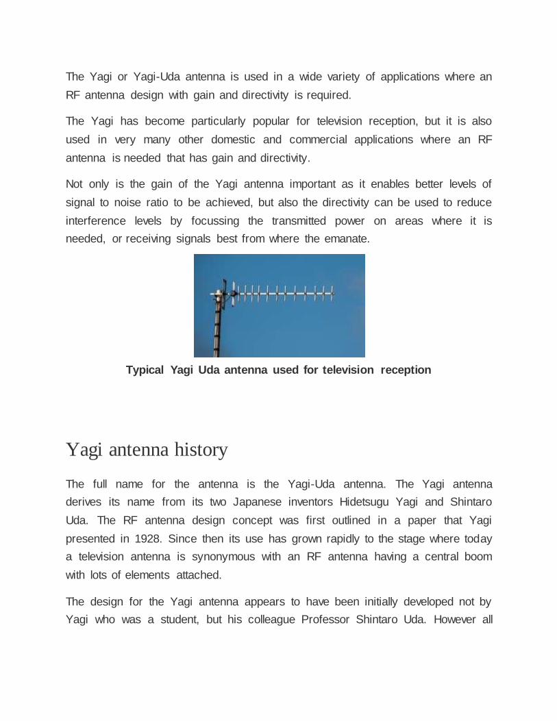
The Yagi has become particularly popular for television reception, but it is also
used in very many other domestic and commercial applications where an RF
antenna is needed that has gain and directivity.
Not only is the gain of the Yagi antenna important as it enables better levels of
signal to noise ratio to be achieved, but also the directivity can be used to reduce
interference levels by focussing the transmitted power on areas where it is
needed, or receiving signals best from where the emanate.
Typical Yagi Uda antenna used for television reception
Yagi antenna history
The full name for the antenna is the Yagi-Uda antenna. The Yagi antenna
derives its name from its two Japanese inventors Hidetsugu Yagi and Shintaro
Uda. The RF antenna design concept was first outlined in a paper that Yagi
presented in 1928. Since then its use has grown rapidly to the stage where today
a television antenna is synonymous with an RF antenna having a central boom
with lots of elements attached.
The design for the Yagi antenna appears to have been initially developed not by
Yagi who was a student, but his colleague Professor Shintaro Uda. However all
the original papers were all in Japanese and accordingly the design was not
publicised outside Japan.
It was Hidetsugu Yagi who wrote papers in English and as a result the design is
often incorrectly only attributed only to Yagi.
Yagi himself did not aim to steal the publicity, in view of his English papers, and
as a result the design now bears the names of both men and is known as the
Yagi-Uda antenna.
Yagi antenna - the basics
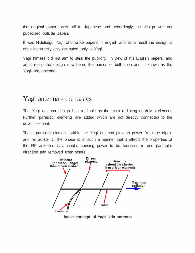
The Yagi antenna design has a dipole as the main radiating or driven element.
Further 'parasitic' elements are added which are not directly connected to the
driven element.
These parasitic elements within the Yagi antenna pick up power from the dipole
and re-radiate it. The phase is in such a manner that it affects the properties of
the RF antenna as a whole, causing power to be focussed in one particular
direction and removed from others.
basic concept of Yagi Uda antenna
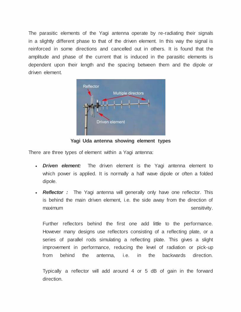
The parasitic elements of the Yagi antenna operate by re-radiating their signals
in a slightly different phase to that of the driven element. In this way the signal is
reinforced in some directions and cancelled out in others. It is found that the
amplitude and phase of the current that is induced in the parasitic elements is
dependent upon their length and the spacing between them and the dipole or
driven element.
Yagi Uda antenna showing element types
There are three types of element within a Yagi antenna:
Driven element: The driven element is the Yagi antenna element to
which power is applied. It is normally a half wave dipole or often a folded
dipole.
Reflector : The Yagi antenna will generally only have one reflector. This
is behind the main driven element, i.e. the side away from the direction of
maximum sensitivity.
Further reflectors behind the first one add little to the performance.
However many designs use reflectors consisting of a reflecting plate, or a
series of parallel rods simulating a reflecting plate. This gives a slight
improvement in performance, reducing the level of radiation or pick-up
from behind the antenna, i.e. in the backwards direction.
Typically a reflector will add around 4 or 5 dB of gain in the forward
direction.
Director: There may be none, one of more reflectors in the Yagi antenna.
The director or directors are placed in front of the driven element, i.e. in the
direction of maximum sensitivity. Typically each director will add around 1
dB of gain in the forward direction, although this level reduces as the
number of directors increases.
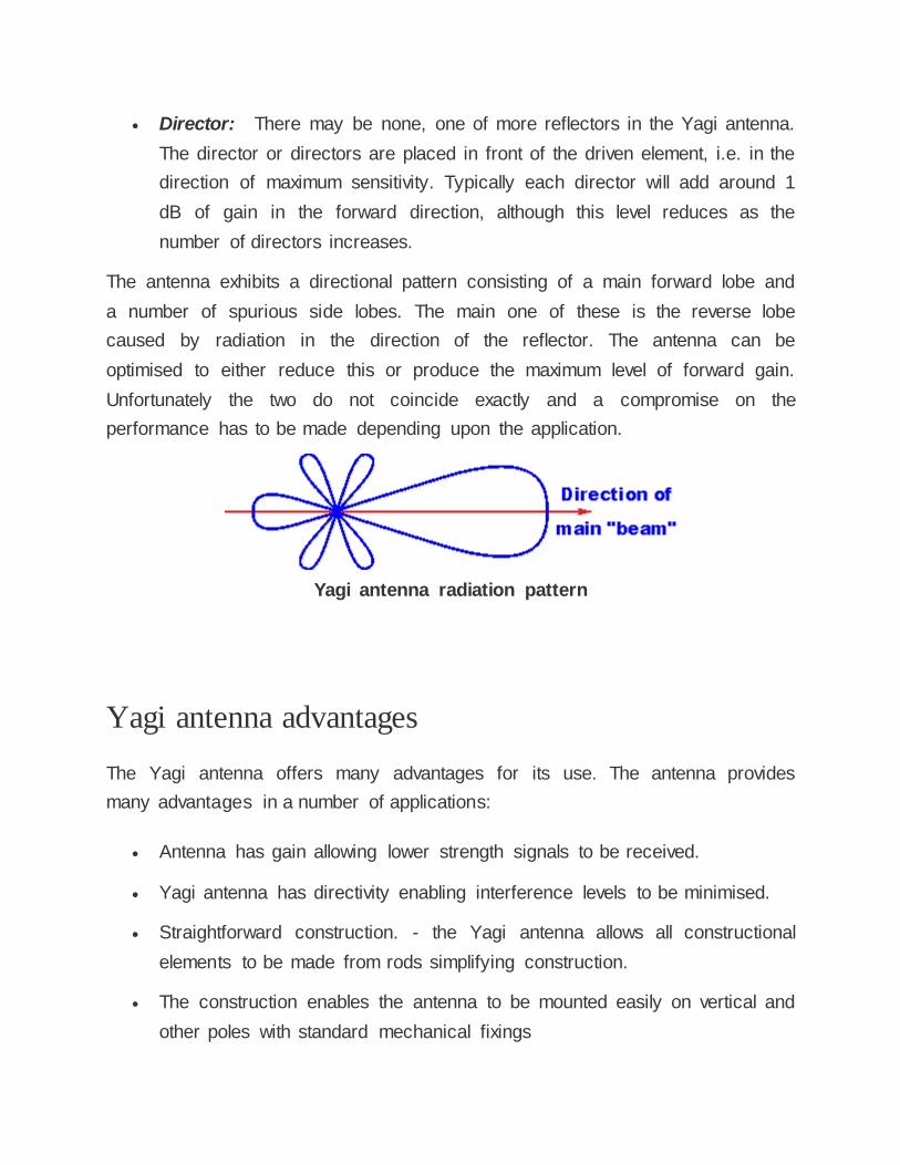
The antenna exhibits a directional pattern consisting of a main forward lobe and
a number of spurious side lobes. The main one of these is the reverse lobe
caused by radiation in the direction of the reflector. The antenna can be
optimised to either reduce this or produce the maximum level of forward gain.
Unfortunately the two do not coincide exactly and a compromise on the
performance has to be made depending upon the application.
Yagi antenna radiation pattern
Yagi antenna advantages
The Yagi antenna offers many advantages for its use. The antenna provides
many advantages in a number of applications:
Antenna has gain allowing lower strength signals to be received.
Yagi antenna has directivity enabling interference levels to be minimised.
Straightforward construction. - the Yagi antenna allows all constructional
elements to be made from rods simplifying construction.
The construction enables the antenna to be mounted easily on vertical and
other poles with standard mechanical fixings
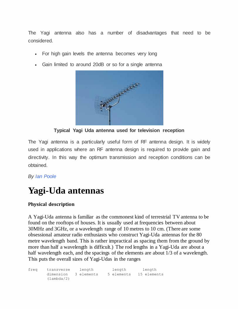
The Yagi antenna also has a number of disadvantages that need to be
considered.
For high gain levels the antenna becomes very long
Gain limited to around 20dB or so for a single antenna
Typical Yagi Uda antenna used for television reception
The Yagi antenna is a particularly useful form of RF antenna design. It is widely
used in applications where an RF antenna design is required to provide gain and
directivity. In this way the optimum transmission and reception conditions can be
obtained.
By Ian Poole
Yagi-Uda antennas
Physical description
A Yagi-Uda antenna is familiar as the commonest kind of terrestrial TV antenna to be found on the rooftops of houses. It is usually used at frequencies between about
30MHz and 3GHz, or a wavelength range of 10 metres to 10 cm. (There are some obsessional amateur radio enthusiasts who construct Yagi-Uda antennas for the 80
metre wavelength band. This is rather impractical as spacing them from the ground by
more than half a wavelength is difficult.) The rod lengths in a Yagi-Uda are about a half wavelength each, and the spacings of the elements are about 1/3 of a wavelength.
This puts the overall sizes of Yagi-Udas in the ranges
freq transverse length length length
dimension 3 elements 5 elements 15 elements
(lambda/2)
30MHz 5 metres 6 metres 13 metres 47 metres
100MHz 1.5 metres 1.8 metres 3.9 metres 14 metres
300MHz 50 cm 60 cm 1.3 metres 4.7 metres
1GHz 15 cm 18 cm 39 cm 1.4 metres
3GHz 5 cm 6 cm 13 cm 47 cm
From this table one can get a very good idea of the approximate frequency of the link by looking at the antenna from afar.
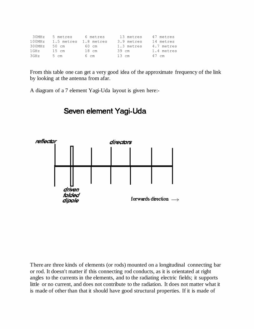
A diagram of a 7 element Yagi-Uda layout is given here:-
There are three kinds of elements (or rods) mounted on a longitudinal connecting bar
or rod. It doesn't matter if this connecting rod conducts, as it is orientated at right angles to the currents in the elements, and to the radiating electric fields; it supports
little or no current, and does not contribute to the radiation. It does not matter what it
is made of other than that it should have good structural properties. If it is made of
conducting metal as are the elements, it can be connected electrically to the directors
and to the reflector (but not to the driven element) without disturbing any of the properties of the antenna.
The three types of element are termed the driving element, the reflector(s) and the director(s). Only the driving element is connected directly to the feeder; the other
elements couple to the transmitter power through the local electromagnetic fields
which induce currents in them. The driving element is often a folded dipole, which by
itself would have a driving point impedance of about 300 ohms to the feeder; but this is reduced by the shunting effect of the other elements, so a typical Yagi-Uda has
driving point impedance in the range 20-90 ohms.
The maximum gain of a Yagi-Uda is limited to an amount given approximately by the
gain of a dipole (1.66 numerical) times the total number of elements. Why is the
power gain proportional to the total number of elements? Well, in an end-fire array of N elements the gain is proportional to N. Consider N isotropic sources, all phased
such that the field contributions in the end-fire direction from each element all add up
in phase in the far field. The field strength (E-field or H-field) of the sum of the
phasors will be N times the field from a single element, so the radiated power density, which is proportional to the square of the fields, will be N^2 times larger. However,
the total POWER delivered to the N elements will be N times larger than that
delivered to a single element, so the power gain in the far field is (N^2)/N = N . Now this argument becomes suspect when the radiation resistance of an element in the
array is different from the radiation resistance of an isolated element, for it is the
currents in the elements which contribute to the far field strengths. In a longish Yagi-Uda, however, the end elements will not see a very different environment for the
addition of an element in the middle of the directors, and the elements in the middle of
the directors are not much affected by how long the array may be. Thus, as a rough "rule of thumb", the factor N (which is empirically about right) may be justified
theoretically.
Many people believe that the gain of a Yagi-Uda rises proportional to the boom length, rather than the number of elements. These two criteria boil down to the same
thing for "sensible element spacings". Clearly, taking the reductio-ad-absurdum of a
three element yagi with indefinitely increasing element spacing, the gain will not rise as the spacing is increased, beyond a certain amount. On the other hand, placing a
great many elements within a short boom length can plainly be seen not to increase
the gain.
Thus, a single element has maximum gain 1.66 = 2.2dBi, a driving element with a
single reflector has maximum gain 3.3 (numerical) or 5.2dBi, a three element antenna
consisting of a single director, driving element, and reflector has maximum gain about
5 (numerical) or 7dBi and a 15 element Yagi-Uda with 13 directors has maximum
gain about 25 (numerical) or 14dBi. There may be compromises in the design to achieve the required front/back ratio, driving point impedance, and bandwidth, so the
gains may be somewhat less than these numbers in a practical antenna.
At a meeting of the RSGB at Sandown Park Racecourse on 21 Feb 1999 I looked at a
stand advertising a 9 element Yagi-Uda antenna with a stated gain of "11.4 dBd" or
11.4dB over the gain of a single dipole. We note that the array factor for this antenna
is limited to the number of elements, in this case 9, and so we would expect the maximum gain to be 10log[10]9 or 9.54 dBd. If we add the gain of the dipole
elements over isotropic as about 2.2dBi we are limited in gain to at most 11.8 dBi. So
we deduce that the people advertising this antenna were either misinformed, or they didn't appreciate the difference between dBd and dBi.
Of course, a naive comparison between a simple dipole antenna and a Yagi-Uda just substitutes one for the other, and then the "gain" may be measured from some field
strength measurements on boresight. However, since the radiation resistances will be
different, and recalling that the definition of relative gain is the ratio of radiated power
levels in a certain direction produced by two antennas having the same TOTAL ACCEPTED INPUT POWER, there is a potent source of confusion here. This is
because the antenna is connected via a feeder to a transmitter whose output level may
be determined in terms of the voltage at its terminals. Thus for the same transmitter and feeder, the accepted powers for the two antennas may be quite different. If one
assumes they are the same, one makes an error in deducing the gain figure from the
field strength measurements.
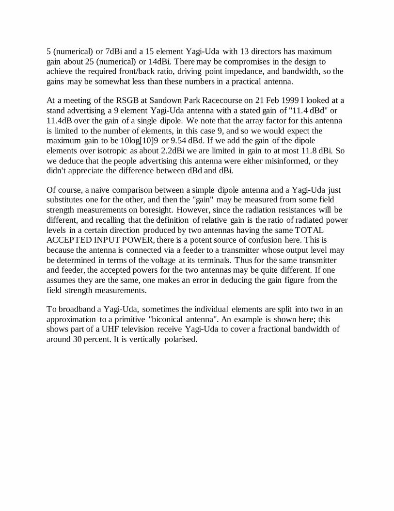
To broadband a Yagi-Uda, sometimes the individual elements are split into two in an
approximation to a primitive "biconical antenna". An example is shown here; this shows part of a UHF television receive Yagi-Uda to cover a fractional bandwidth of
around 30 percent. It is vertically polarised.
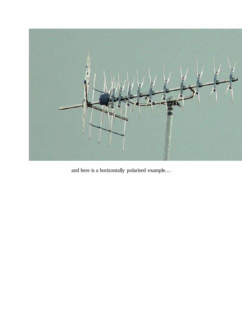
and here is a horizontally polarised example....
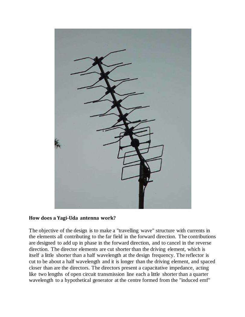
How does a Yagi-Uda antenna work?
The objective of the design is to make a "travelling wave" structure with currents in the elements all contributing to the far field in the forward direction. The contributions
are designed to add up in phase in the forward direction, and to cancel in the reverse
direction. The director elements are cut shorter than the driving element, which is itself a little shorter than a half wavelength at the design frequency. The reflector is
cut to be about a half wavelength and it is longer than the driving element, and spaced
closer than are the directors. The directors present a capacitative impedance, acting
like two lengths of open circuit transmission line each a little shorter than a quarter wavelength to a hypothetical generator at the centre formed from the "induced emf"
set up by the impinging fields. See the SMITH chart . Similarly, the reflector presents
an inductive impedance to a hypothetical emf generator at its centre. The effects of the spacings and the current progressive phase shifts mean that the contributions of the
current in the various elements to the radiated fields all add up in phase.
For a closely spaced driving element and parasitic element, isolated from each other
as far a electrical conduction currents are concerned, the currents are oppositely
directed as can be seen in the discussion on folded dipoles with the folds cut off. As
the spacing is increased, the currents remain oppositely directed until when the spacing is a half-wavelength, the contributions to the far field add up in phase in the
"endfire direction", as can be seen from the discussion on array antennas.
If the director elements are cut a little short, their self-impedance is capacitative and
they have to be spaced a little closer than a half-wavelength in order to maintain
equality of phase in the radiation contribution with the wave arriving from the previous director. The currents in successive elements thus roughly have the pattern
....up down up down up down ......
but will all be very nearly equal in magnitude to each other. There is also some
progressive phase shift as the wave advances, caused by the fact that the directors are
cut short (capacitative).
The field pattern on the yagi directors therefore advances as a travelling wave in the
forward direction, with wavelength approximately equal to three director spacings. This can be seen in the table at the top of this page; at 30MHz the wavelength
(lambda) is 10 metres so for a 15 element Yagi array, the length given as 47 metres is
nearly five wavelengths, or 15 elements divided by 3.
So the travelling wave structure supports a non-attenuating wave in the forward
direction, and the currents in the directors are all approximately the same size, although with a progressive phase delay. It is for this reason that, for moderate
numbers of elements, the forward gain is proportional to the number of elements.
The reflector has an induced current in it that contributes a wave in the backwards direction that just cancels the backward wave from the driven element. Only a little
power is radiated backwards. The net power radiated by the reflector current has to go
somewhere, so it appears as a contribution in the forward direction. The length and the spacing of the reflector have a strong influence on the residual backward radiation
from the Yagi-Uda. Typically the reflector will be spaced by 1/8 to 1/4 of a
wavelength, and the directors by about 1/3 wavelength each.
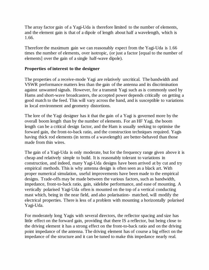
The array factor gain of a Yagi-Uda is therefore limited to the number of elements,
and the element gain is that of a dipole of length about half a wavelength, which is 1.66.
Therefore the maximum gain we can reasonably expect from the Yagi-Uda is 1.66 times the number of elements, over isotropic, (or just a factor [equal to the number of
elements] over the gain of a single half-wave dipole).
Properties of interest to the designer
The properties of a receive-mode Yagi are relatively uncritical. The bandwidth and VSWR preformance matters less than the gain of the antenna and its discrimination
against unwanted signals. However, for a transmit Yagi such as is commonly used by
Hams and short-wave broadcasters, the accepted power depends critically on getting a good match to the feed. This will vary across the band, and is susceptible to variations
in local environment and geometry distortions.
The lore of the Yagi designer has it that the gain of a Yagi is governed more by the
overall boom length than by the number of elements. For an HF Yagi, the boom
length can be a critical design factor, and the Ham is usually seeking to optimise the
forward gain, the front-to-back ratio, and the construction techniques required. Yagis having thick rod elements (in terms of a wavelength) are better-behaved than those
made from thin wires.
The gain of a Yagi-Uda is only moderate, but for the frequency range given above it is
cheap and relatively simple to build. It is reasonably tolerant to variations in
construction, and indeed, many Yagi-Uda designs have been arrived at by cut and try empirical methods. This is why antenna design is often seen as a black art. With
proper numerical simulation, useful improvements have been made to the empirical
designs. Trade-offs may be made between the various factors, such as bandwidth, impedance, front-to-back ratio, gain, sidelobe performance, and ease of mounting. A
vertically polarised Yagi-Uda often is mounted on the top of a vertical conducting
mast which, being in the near field, and also polarisation- matched, will modify the
electrical properties. There is less of a problem with mounting a horizontally polarised Yagi-Uda.
For moderately long Yagis with several directors, the reflector spacing and size has little effect on the forward gain, providing that there IS a reflector, but being close to
the driving element it has a strong effect on the front-to-back ratio and on the driving
point impedance of the antenna. The driving element has of course a big effect on the impedance of the structure and it can be tuned to make this impedance nearly real.
The directors form the majority of the travelling wave structure and amply repay care
in design.
As with all antenna simulation exercises, it is very easy to fall into the trap that one
can calculate properties which one cannot reliably measure. It is therefore questionable as to the utility of such calculations at present. There are a large number
of parameters to be chosen by the designer; the individual spacings, lengths, and
diameters of the elements give three adjustable parameters per element.
There is a fashion in 1999 to write simulation papers (for the academic journals on
antennas), which are unsupported in any way by measurements. As a warning to the
reader, if you see an antenna design based on simulation only, and unsupported by any experimental verification, it is wise to be very skeptical about its applicability to a real
antenna construction, and you should certainly not believe the performance figures it
quotes for such an antenna, without investigating the performance further.
Pitfalls in design and construction of Yagi-Uda antennas
There are many published "cookbook" style designs for Yagi-Uda antennas. Often these have been arrived at by empirical "cut-and-try" methods, or else simulations. If
one plays around with the lengths and spacings of the elements, using different tube
diameters, with, for example, a NEC simulation package one rapidly realises that it is much easier to make a Yagi-Uda structure which has broadside boresight max-gain
directions than it is to make an endfire Yagi-Uda. There are many more combinations
of parameters which give broadside main beams than give end fire main beams. One deduces from this observation that many, if not most, practical Yagi-Uda antennas do
not work "as advertised" or "as desired", particularly if the build process departs from
the exact specifications. Caveat emptor!
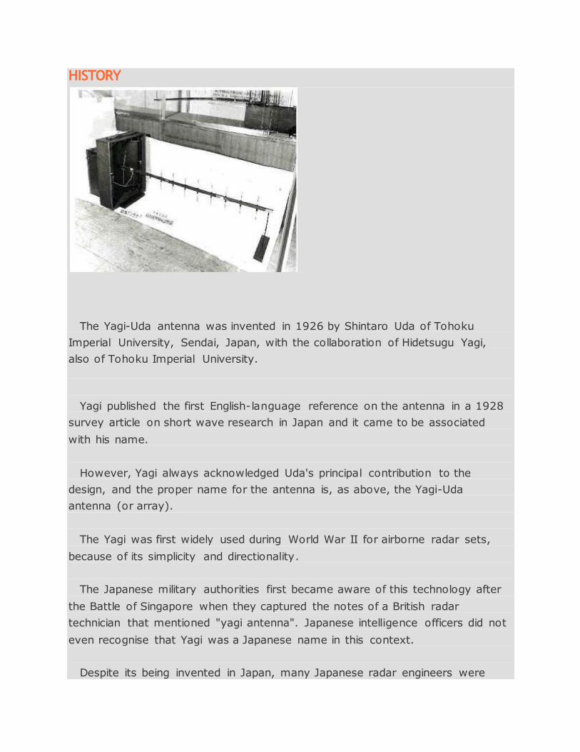
HISTORY
The Yagi-Uda antenna was invented in 1926 by Shintaro Uda of Tohoku
Imperial University, Sendai, Japan, with the collaboration of Hidetsugu Yagi,
also of Tohoku Imperial University.
Yagi published the first English-language reference on the antenna in a 1928
survey article on short wave research in Japan and it came to be associated
with his name.
However, Yagi always acknowledged Uda's principal contribution to the
design, and the proper name for the antenna is, as above, the Yagi-Uda
antenna (or array).
The Yagi was first widely used during World War II for airborne radar sets,
because of its simplicity and directionality.
The Japanese military authorities first became aware of this technology after
the Battle of Singapore when they captured the notes of a British radar
technician that mentioned "yagi antenna". Japanese intelligence officers did not
even recognise that Yagi was a Japanese name in this context.
Despite its being invented in Japan, many Japanese radar engineers were
unaware of the design until very late in the war, due to internal fighting
between the Army and Navy. A horizontally polarized array can be seen under
the left leading edge of Grumman F4F, F6F, TBF Avenger carrier based Navy
aircraft.
Yagi-Uda antennas are widely used by amateur radio operators worldwide for
communication on frequencies from shortwave, through VHF/UHF, and into
microwave bands. Hams often homebrew this type of antenna, and have
provided many technical papers and software to the engineering community.