Embed Size (px)
Citation preview

Undergraduate Research ExperienceDeformation Machining
Dylan SylvesterDr. Bethany Woody
Dr. Scott Smith
What is deformation machining?
Single Point Incremental Forming
No expensive tooling Simple 3-axis Machine
Simple 3-axis Machine
Sheet metal is ‘pushed’ to shape
Sheet metal is ‘pushed’ to shape
Thin Structure Machining
Monolithic PiecesMonolithic Pieces Reduced Assembly costReduced Assembly cost
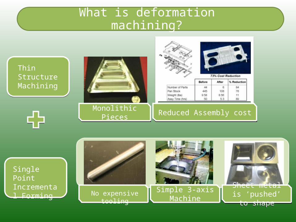
Deformation Machining Advantages
Create geometries otherwise impossibleCreate geometries otherwise impossible
Extra material in the radius = added weight
Potential for weight and cost reductionPotential for weight and cost reduction
Eliminate the need for expensive 5 axis machinesEliminate the need for expensive 5 axis machines
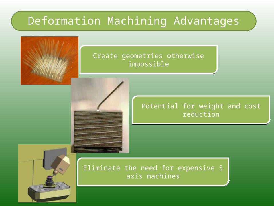
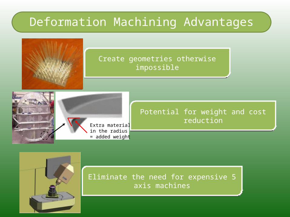
Deformation Machining Advantages
Create geometries otherwise impossibleCreate geometries otherwise impossible
Potential for weight and cost reductionPotential for weight and cost reduction
Eliminate the need for expensive 5 axis machinesEliminate the need for expensive 5 axis machines
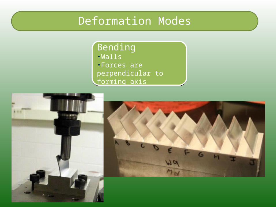
Deformation Modes
Bending•Walls•Forces are perpendicular to forming axis
Bending•Walls•Forces are perpendicular to forming axis
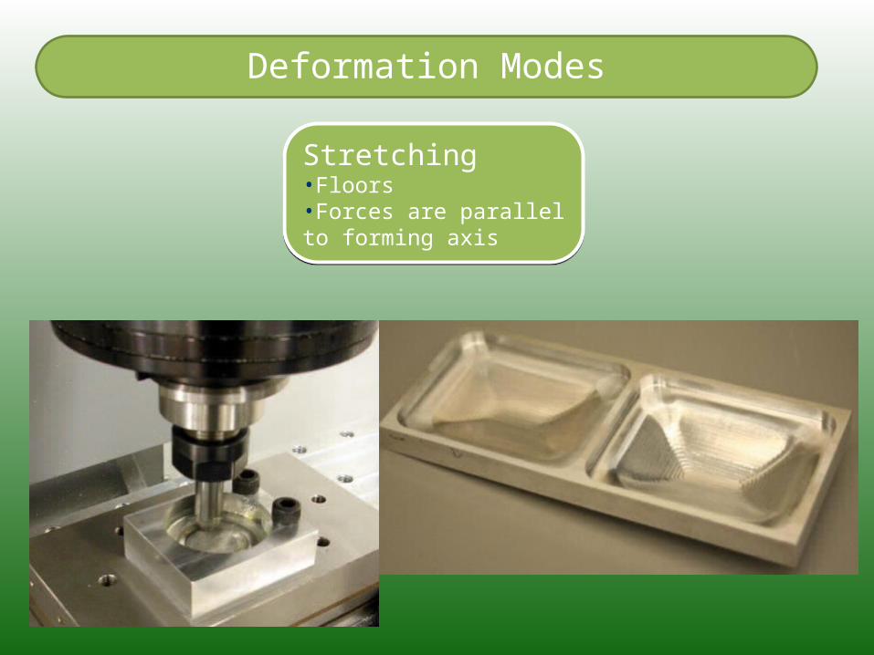
Stretching•Floors•Forces are parallel to forming axis
Stretching•Floors•Forces are parallel to forming axis
Deformation Modes
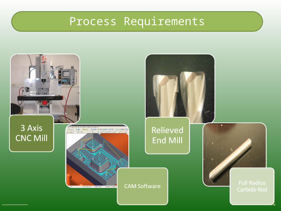
Process Requirements
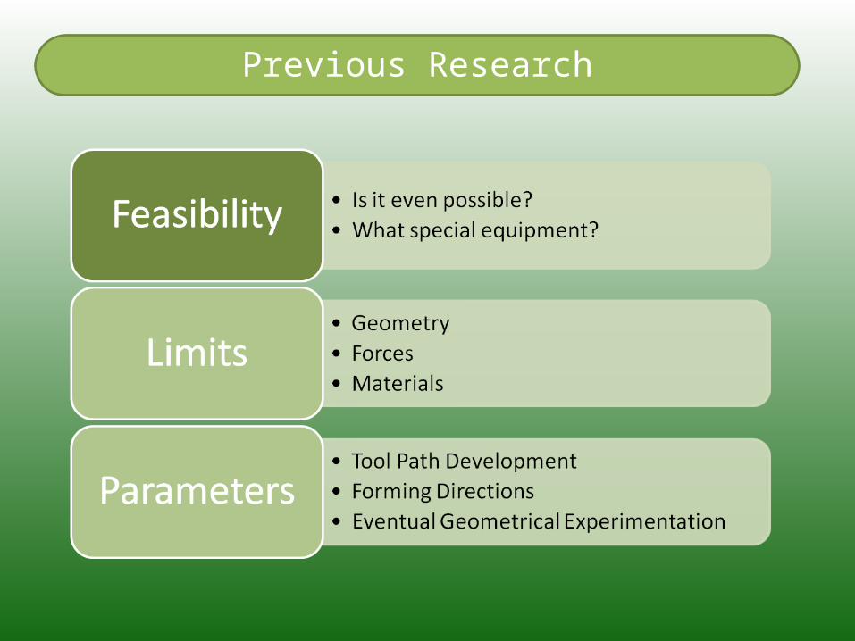
Previous Research
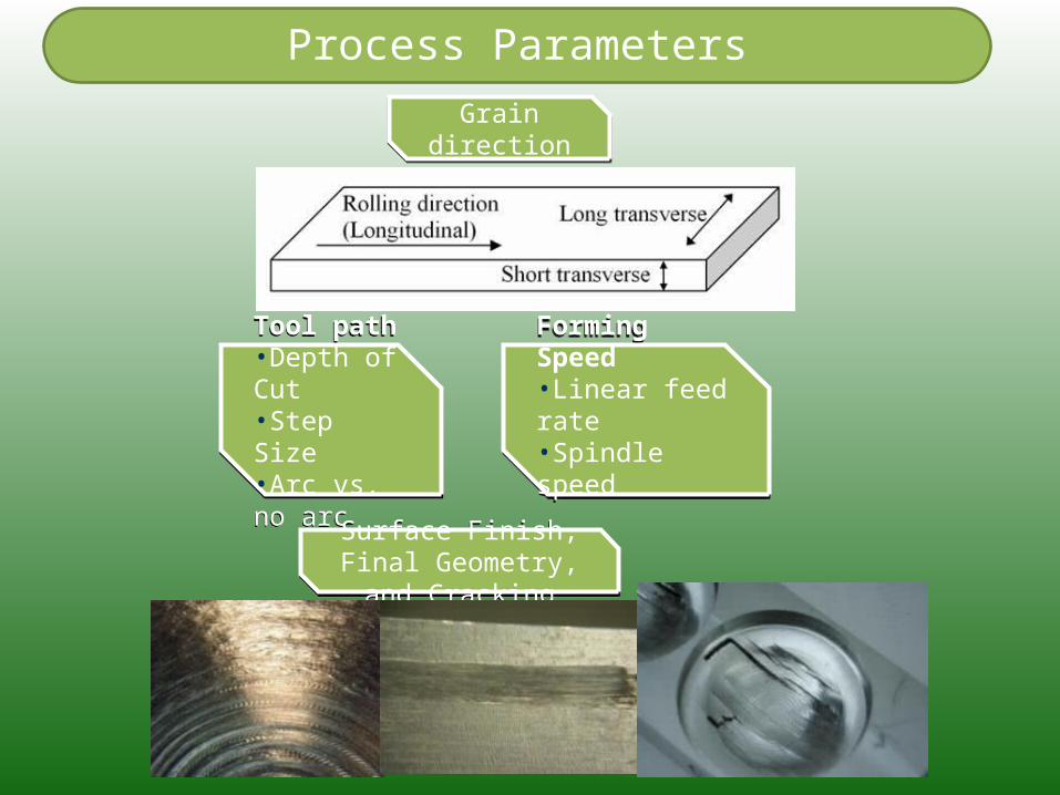
Process Parameters
Grain directionGrain direction
Tool path•Depth of Cut•Step Size•Arc vs. no arc
Tool path•Depth of Cut•Step Size•Arc vs. no arc
Forming Speed•Linear feed rate•Spindle speed
Forming Speed•Linear feed rate•Spindle speed
Surface Finish, Final Geometry, and Cracking
Surface Finish, Final Geometry, and Cracking
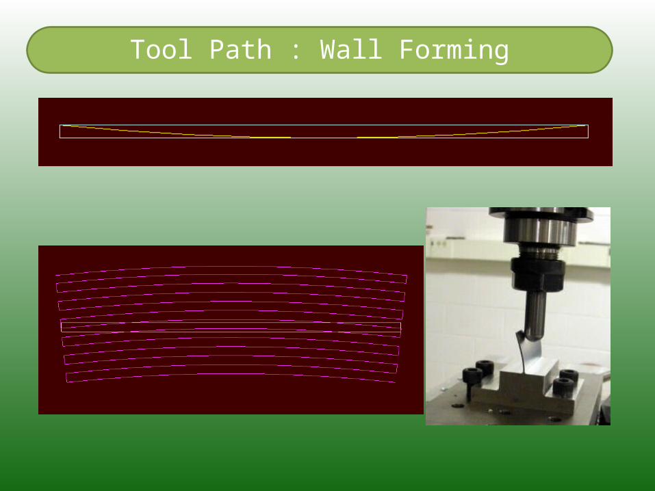
Tool Path : Wall Forming
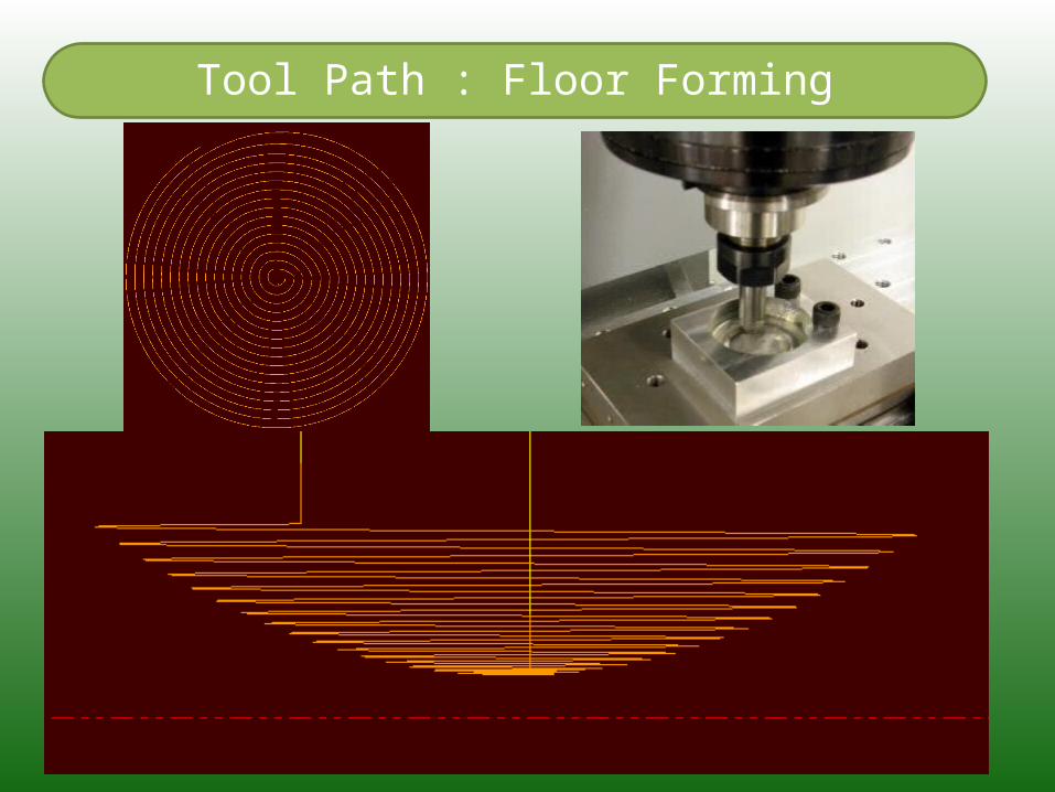
Tool Path : Floor Forming
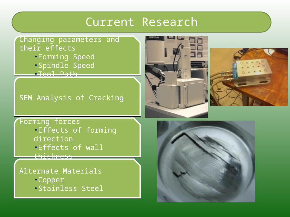
Current Research
Changing parameters and their effects•Forming Speed•Spindle Speed•Tool Path
Changing parameters and their effects•Forming Speed•Spindle Speed•Tool Path
SEM Analysis of CrackingSEM Analysis of Cracking
Forming forces•Effects of forming direction•Effects of wall thickness
Forming forces•Effects of forming direction•Effects of wall thickness
Alternate Materials•Copper•Stainless Steel
Alternate Materials•Copper•Stainless Steel
Forming Speed and Spindle Speed
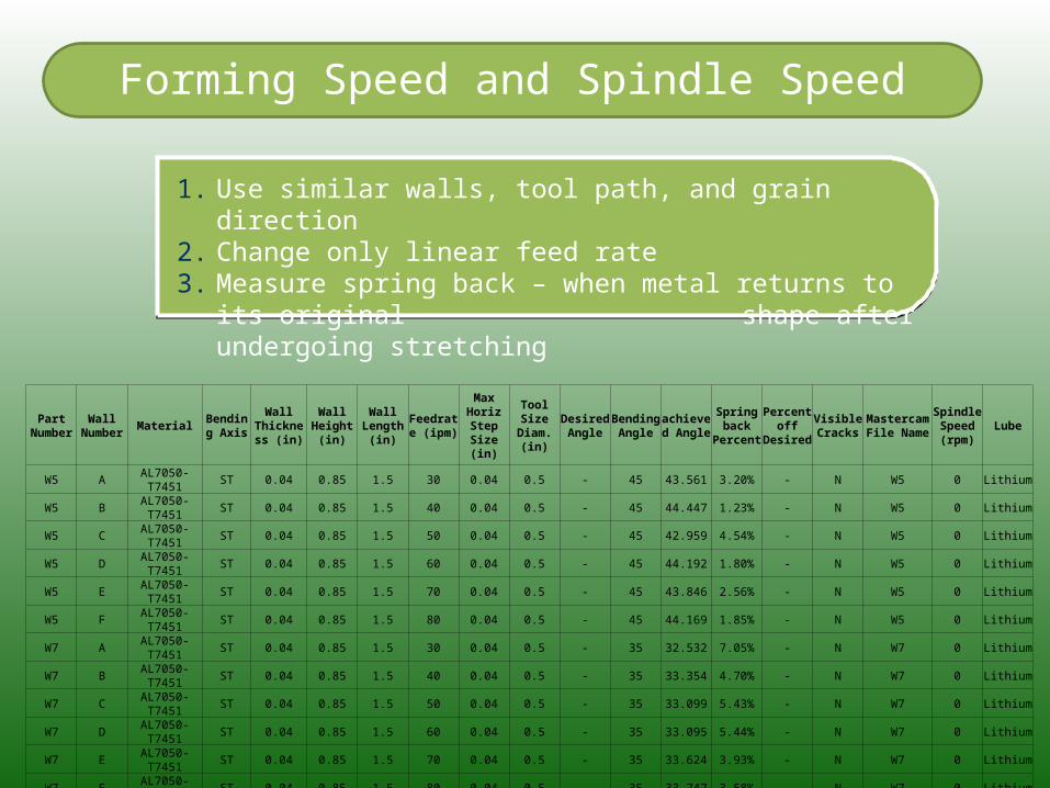
1. Use similar walls, tool path, and grain direction2. Change only linear feed rate3. Measure spring back – when metal returns to its original
shape after undergoing stretching
Part Number
Wall Number Material Bending
Axis
Wall Thickness
(in)
Wall Height
(in)
Wall Length
(in)
Feedrate (ipm)
Max Horiz Step Size
(in)
Tool Size Diam. (in)
Desired Angle
Bending Angle
achieved Angle
Spring back
Percent
Percent off
Desired
Visible Cracks
Mastercam File Name
Spindle Speed (rpm)
Lube
W5 A AL7050-T7451 ST 0.04 0.85 1.5 30 0.04 0.5 - 45 43.561 3.20% - N W5 0 Lithium
W5 B AL7050-T7451 ST 0.04 0.85 1.5 40 0.04 0.5 - 45 44.447 1.23% - N W5 0 Lithium
W5 C AL7050-T7451 ST 0.04 0.85 1.5 50 0.04 0.5 - 45 42.959 4.54% - N W5 0 Lithium
W5 D AL7050-T7451 ST 0.04 0.85 1.5 60 0.04 0.5 - 45 44.192 1.80% - N W5 0 Lithium
W5 E AL7050-T7451 ST 0.04 0.85 1.5 70 0.04 0.5 - 45 43.846 2.56% - N W5 0 Lithium
W5 F AL7050-T7451 ST 0.04 0.85 1.5 80 0.04 0.5 - 45 44.169 1.85% - N W5 0 Lithium
W7 A AL7050-T7451 ST 0.04 0.85 1.5 30 0.04 0.5 - 35 32.532 7.05% - N W7 0 Lithium
W7 B AL7050-T7451 ST 0.04 0.85 1.5 40 0.04 0.5 - 35 33.354 4.70% - N W7 0 Lithium
W7 C AL7050-T7451 ST 0.04 0.85 1.5 50 0.04 0.5 - 35 33.099 5.43% - N W7 0 Lithium
W7 D AL7050-T7451 ST 0.04 0.85 1.5 60 0.04 0.5 - 35 33.095 5.44% - N W7 0 Lithium
W7 E AL7050-T7451 ST 0.04 0.85 1.5 70 0.04 0.5 - 35 33.624 3.93% - N W7 0 Lithium
W7 F AL7050-T7451 ST 0.04 0.85 1.5 80 0.04 0.5 - 35 33.747 3.58% - N W7 0 Lithium
Forming Speed and Spindle Speed
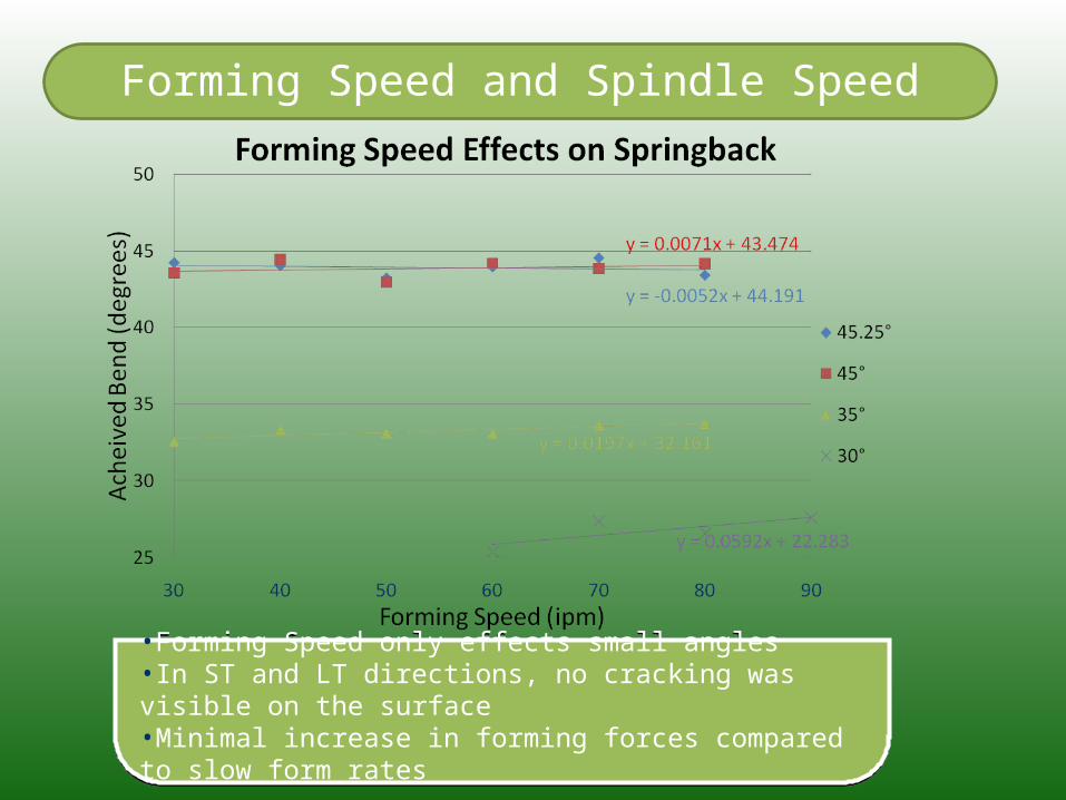
•Forming Speed only effects small angles•In ST and LT directions, no cracking was visible on the surface•Minimal increase in forming forces compared to slow form rates
•Forming Speed only effects small angles•In ST and LT directions, no cracking was visible on the surface•Minimal increase in forming forces compared to slow form rates
Forming Speed and Spindle Speed
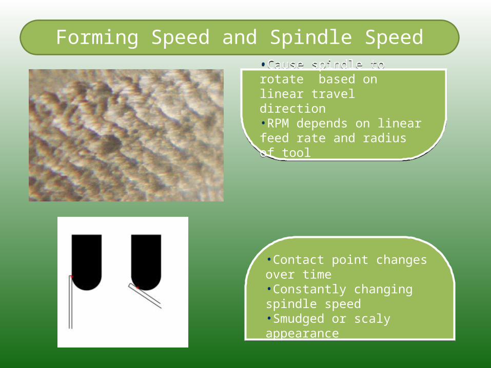
•Cause spindle to rotate based on linear travel direction•RPM depends on linear feed rate and radius of tool
•Cause spindle to rotate based on linear travel direction•RPM depends on linear feed rate and radius of tool
•Contact point changes over time•Constantly changing spindle speed•Smudged or scaly appearance
•Contact point changes over time•Constantly changing spindle speed•Smudged or scaly appearance
Forming Forces
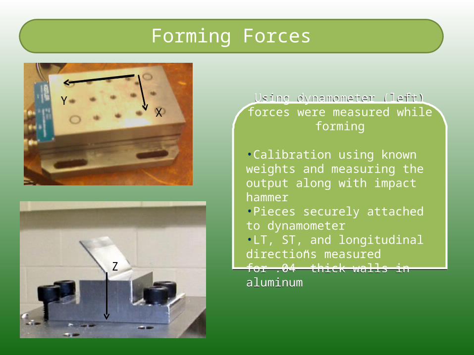
Using dynamometer (left) forces were measured while forming
•Calibration using known weights and measuring the output along with impact hammer•Pieces securely attached to dynamometer•LT, ST, and longitudinal directions measured for .04” thick walls in aluminum
Using dynamometer (left) forces were measured while forming
•Calibration using known weights and measuring the output along with impact hammer•Pieces securely attached to dynamometer•LT, ST, and longitudinal directions measured for .04” thick walls in aluminum
YX
Z
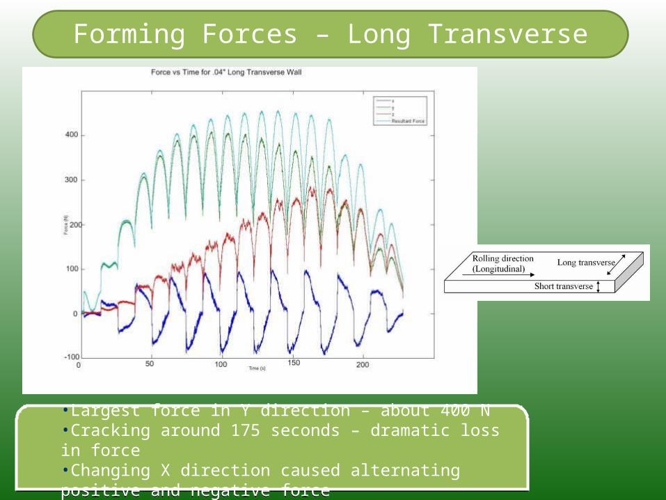
Forming Forces – Long Transverse
•Largest force in Y direction – about 400 N•Cracking around 175 seconds – dramatic loss in force•Changing X direction caused alternating positive and negative force
•Largest force in Y direction – about 400 N•Cracking around 175 seconds – dramatic loss in force•Changing X direction caused alternating positive and negative force
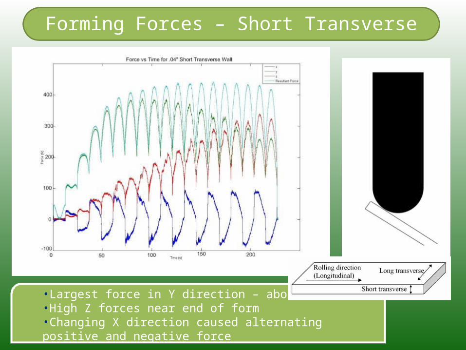
Forming Forces – Short Transverse
•Largest force in Y direction – about 380 N•High Z forces near end of form•Changing X direction caused alternating positive and negative force
•Largest force in Y direction – about 380 N•High Z forces near end of form•Changing X direction caused alternating positive and negative force
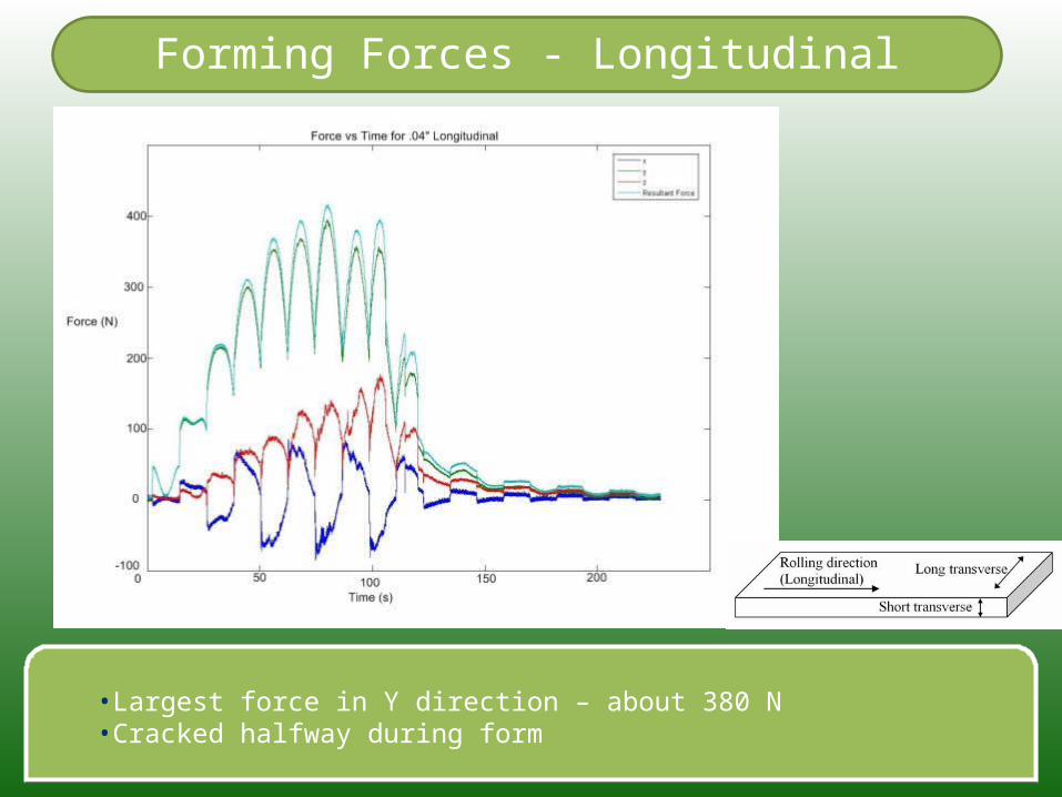
Forming Forces - Longitudinal
•Largest force in Y direction – about 380 N•Cracked halfway during form•Largest force in Y direction – about 380 N•Cracked halfway during form
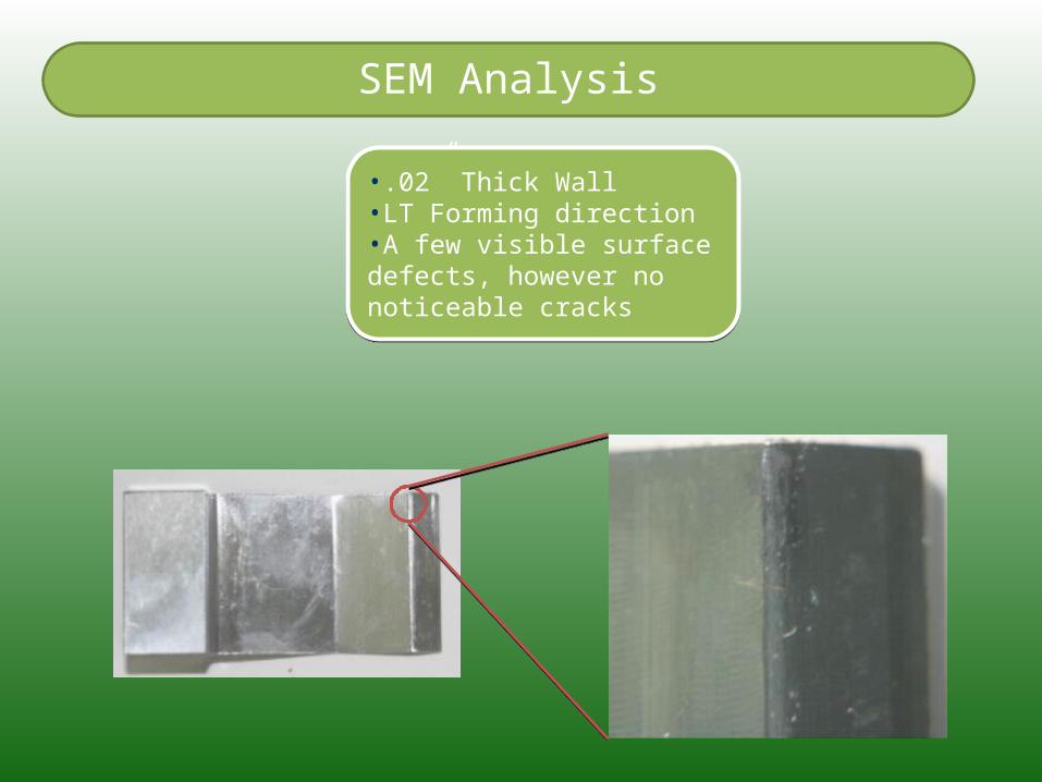
•.02” Thick Wall•LT Forming direction•A few visible surface defects, however no noticeable cracks
•.02” Thick Wall•LT Forming direction•A few visible surface defects, however no noticeable cracks
SEM Analysis
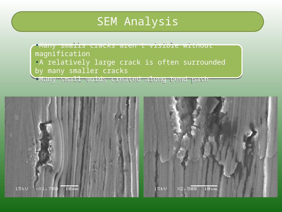
•Many smalls cracks aren’t visible without magnification•A relatively large crack is often surrounded by many smaller cracks•Many small voids created along bend path
•Many smalls cracks aren’t visible without magnification•A relatively large crack is often surrounded by many smaller cracks•Many small voids created along bend path
SEM Analysis
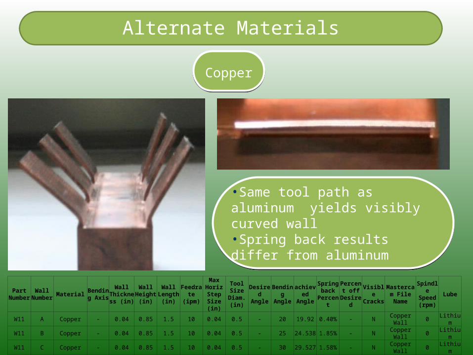
Alternate Materials
CopperCopper
•Same tool path as aluminum yields visibly curved wall•Spring back results differ from aluminum
•Same tool path as aluminum yields visibly curved wall•Spring back results differ from aluminum
Part Number
Wall Number Material Bending
Axis
Wall Thickness
(in)
Wall Height
(in)
Wall Length
(in)
Feedrate (ipm)
Max Horiz
Step Size (in)
Tool Size Diam.
(in)
Desired Angle
Bending Angle
achieved Angle
Spring back
Percent
Percent off
Desired
Visible Cracks
Mastercam File Name
Spindle Speed (rpm)
Lube
W11 A Copper - 0.04 0.85 1.5 10 0.04 0.5 - 20 19.92 0.40% - N Copper Wall 0 LithiumW11 B Copper - 0.04 0.85 1.5 10 0.04 0.5 - 25 24.538 1.85% - N Copper Wall 0 LithiumW11 C Copper - 0.04 0.85 1.5 10 0.04 0.5 - 30 29.527 1.58% - N Copper Wall 0 LithiumW11 D Copper - 0.04 0.85 1.5 10 0.04 0.5 - 35 34.7 0.86% - N Copper Wall 0 LithiumW11 E Copper - 0.04 0.85 1.5 10 0.04 0.5 - 40 39.513 1.22% - N Copper Wall 0 LithiumW11 F Copper - 0.04 0.85 1.5 10 0.04 0.5 - 45 44.617 0.85% - N Copper Wall 0 Lithium
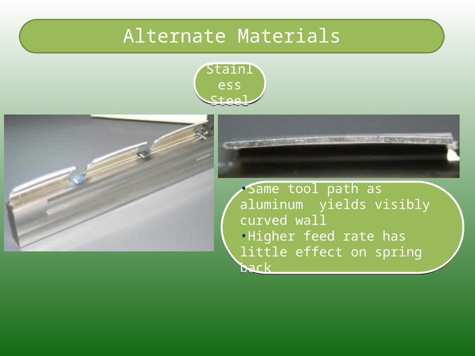
Alternate Materials
Stainless Steel
Stainless Steel
•Same tool path as aluminum yields visibly curved wall•Higher feed rate has little effect on spring back
•Same tool path as aluminum yields visibly curved wall•Higher feed rate has little effect on spring back
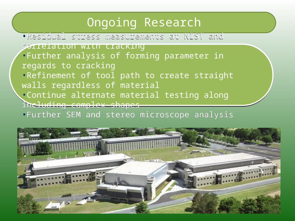
Ongoing Research
•Residual stress measurements at NIST and correlation with cracking•Further analysis of forming parameter in regards to cracking•Refinement of tool path to create straight walls regardless of material•Continue alternate material testing along including complex shapes•Further SEM and stereo microscope analysis
•Residual stress measurements at NIST and correlation with cracking•Further analysis of forming parameter in regards to cracking•Refinement of tool path to create straight walls regardless of material•Continue alternate material testing along including complex shapes•Further SEM and stereo microscope analysis